Embed Size (px)
Citation preview

Subject: Precautions of replacement from RV-6SD/6SDL to RV-7FR-D/7FRL-D
Applicable to: RV-6SD, RV-6SDLRV-7FR-D, RV-7FRL-D
Thank you for your continued support of Mitsubishi industrial MELFA series robots.
This Technical News explains in detail the precautions for the replacement of RV-6SD/6SDLvertical multiple-joint type robots with RV-7FR-D or RV-7FRL-D robots.
MITSUBISHI ELECTRIC CORPORATION
MELFA Technical NewsBFP-A6079-0213E-*
January 2018
(1/8)
Contents
1. Configurations of the models (Compatible models for replacement) ……………… 2
2. Specifications comparison …………………………………………………………….. 22. 1 Specifications of the robot arm …………………………………………………… 22. 2 Dimensions of the robot arm and diagram of the operating range …………… 32. 3 Specifications of the controller ……………………………………………………. 62. 4 Outside dimensions of the controller …………………………………………….. 62. 5 Options ……………………………………………………………………………… 7
3. Compatibility …………………………………………………………………………….. 83. 1 Compatibility of the robot arm ……………………………………………………. 83. 2 Compatibility of the controller ……………………………………………………. 83. 3 Precautions of the extension function for GOT direct connection ……………. 8
Changes for the Better
Mitsubishi Electric Corporation Robot Industrial

Model ControllerRV-7FR-D CR800-07VDRV-7FRL-D CR800-07VD
Model ControllerRV-6SD CR2DA-711, CR3D-711MRV-6SDL CR2DA-711, CR3D-711M
1. Configurations of the models (Compatible model for replacement)The following shows the compatible models of robot arms and controllers for the replacement of RV-6S/RV-6SL/RV-6SD/6SDL/6SQ/
6SQLJ to RV-7F-D/Q or RV-7FL-D/Q.
Precautions for the replacement of RV-6SD/6SDL with RV-7FR-D or RV-7FRL-D.
(2/8)
Mitsubishi Electric Corporation Industrial ROBOT MELFA Technical News No. BFP-A6079-0213-*
2.1 Specifications of the robot armThe following table compares the robot arm specifications between old and new models.
2. Specifications comparison
kgArm length mm 280 + 315 380 + 425 340 + 370 435 + 470
mm 695 902 713 908J1J2 240 (-115 to +125) 240 (-110 to +130)J3 273 (-107 to +166) 295 (-129 to +166) 156 (0 to +156) 162 (0 to +162)J4J5J6J1 401 250 360 288J2 321 267 401 321J3 401 267 450 360J4J5J6
mm/sec 9300 8500 11064 10977sec 0.47 0.5 0.32 0.35mm°Ckg 58 60 65 67
J4J5J6J4J5J6
Note 1) Value of mechanical interface side when synthesizing all axesNote 2) Value of 1kg of load and back-and-forth movement for a vertical distance of 25mm and horizontal distance of 300mmNote 3) Can also be used a as a spare line (0.2sq 4-pair cable) for conventional models.
Note 6) In the wall type specification, operation range of the J1-axis is restricted.
Mass
degree/s
Primary: φ6 × 2 Secondary: φ4 × 8
Color: Light gray(Reference Munsell color: 0.08GY7.64/0.81)
5m (connector on both ends) 5m (connector on both ends)
16.2
0 to 40
0.290.29
6.8616.2
4.512
Note 4) Please contact a Mitsubishi Electric dealer since the environment resistance may not be secured depending on the characteristics of oil you use.In addition, an air purge is required. For the details, refer to the specifications manual.
Nm
0.45
12
0.046
Note 5) Preservation of cleanliness levels depends on conditions of a downstream flow of 0.3m/s in the clean room and internal robot suctioning.A φ8-mm coupler for suctioning is provided at the back of the base.
Tolerable moment
Tolerable inertiakg, m2
AC servomotorAbsolute encoder
340 (±170)
337
0 to 40±0.02
480 (±240)
7
720450
6Floor type, ceiling type, (wall type Note 6)
450
SpecificationsOld models
None: Standard (oil mist) Note 4)/C: Clean Note 5)Standard: IP65 (J4 to J6), IP54 (J1 to J3)/C: Class 10 (0.3µm)
6
720 (±360)
Floor type, ceiling type, (wall type Note 6)
0.1Hand: 8 input points/8 output points
Signal line of the multi-function hand sensor and force sensor(24-pin)
LAN × 1<100BASE-TX> (8-pin) Note 3)
0.45
Hand: 8 input points/8 output points (forearm),8 spare wires: AWG#27 (0.1mm2)
Vertical multiple-joint typeAC servomotor
Absolute encoder6
Positioning repeatability
Degree
660
Machine classProtection degree
RV-7FR/7FRM/7FRC-D RV-7FRL/7FRLM/7FRLC-DRV-6SDL/6SDLCRV-6SD/6SDC
None: Standard/M: Oil mist Note 4)/C: Clean Note 5)
TypeNew models
Ambient temperature
Operation range
Maximum speed
Maximum reach radius
Structure
Standard: IP40/M: IP67/C: ISO class 3
Unit
Model
±0.02
320 (±160)
352
240 (±120)720 (±360)
Color: Light gray(Reference Munsell color: 0.6B7.6/0.2)
400 (±200)
227 (-92 to +135)
240 (±120)
Vertical multiple-joint type
Tool pneumatic piping
PaintMachine cable
Primary: φ6 × 2 Secondary: φ6 × 8, φ4 × 4 (wrist inside)
Degree of freedom
Maximum composite speed Note 1)
Position detection typeLoad capacity
Drive system
Cycle time Note 2)
Installation
Tool wiring

Precautions of replacement from RV-6SD/6SDL to RV-7FR-D/RV-7FRL-D
(3/8)
Mitsubishi Electric Corporation Industrial ROBOT MELFA Technical News No. BFP-A6079-0213-*
2.2 Dimensions of the robot arm and diagram of the operating range2.2.1 Robot arm installation dimensions and mechanical interface
The installation dimensions and mechanical interface have changed. Refer to the following diagrams.
Mechanical interface
New models: RV-7FR-D, RV-7FRL-DOld models: RV-6SD/6SDL
Installation dimensions of the robot arm Installation dimensions of the robot arm
Note 1)
Note 1) Thread engagement should be within 7.5 to 8.5mm. Note 1) Thread engagement should be within 7.5 to 8mm.
Note 2) This value indicates the dimensions of standard specification.
The dimensions for oil mist specification and clean specification are 3.5mm, and 6.5mm for SH** specification.
Note 1)
Note 2)
Mechanical interface
(Installationreference surface)
(Inst
alla
tion
refe
renc
e su
rface
)10
2.5
102.
5
(205
)
124.
5
124.5
102.5 102.5 4-φ9 installation hole
(205)
245
162
245.7
Rz2
5
Rz25
φ40h8P.C.D.φ31.5
φ20H7 depth 6
45°φ5H7 depth 8
4-M5 screw depth 8
φ40h8 depth 6.5
φ31.5
φ20H7 depth 8.5
45°φ5H7 depth 9
4-M5 screw depth 9
2-φ6 hole (φ8 hole preparedfor positioning)
122 16
0
204
140
205
115
102.5
96
4-φ9 installationhole
115
(Inst
alla
tion
refe
renc
e su
rface
)(Installationreference surface)
Rz25
Rz25

(4/8)
Mitsubishi Electric Corporation Industrial ROBOT MELFA Technical News No. BFP-A6079-0213-*
2.2.2 Dimensions of the robot arm and diagram of the operating range1) Comparison between RV-7FR-D and RV-6SD
The major differences in dimensions of the robot and operatingrange are described below.
RV-7FR-D (shaded area)(Area in -240˚ to +240˚)
RV-6SD(dot hatching area)(Area in -170˚ to +170˚)
RV-7FR-D (shaded area)(Area in -240˚ to +240˚)
RV-6SD reverse area (dot hatching area)(Area in -170˚ to +170˚)
• RV-6SD can be replaced with RV-7FR-D because its operating range is within the one of RV-7FR-D.
• For the reverse area of RV-6SD, refer to caution 1 below.
Arm downward facing limit line
Robot installation surface
RV-7FR-D
RV-6SD
Arm downward facingsingular point boundary line
Caution 1: The reverse area of RV-6SD is compatible by combining the J1-axis operating area (±240˚) and forward operating area of RV-7FR-D.

(5/8)
Mitsubishi Electric Corporation Industrial ROBOT MELFA Technical News No. BFP-A6079-0213-*
2.2.2 Dimensions of the robot arm and diagram of the operating range1) Comparison between RV-7FRL-D and RV-6SDL
The major differences in dimensions of the robot and operating range are described below.
• RV-6SDL can be replaced with RV-7FRL-D because its operating range is within the one of RV-7FRL-D.
• For the reverse area of RV-6SDL, refer to caution 1 below.
RV-7FRL-D (shaded area)(Area in -240˚ to +240˚)
RV-6SDL(dot hatching area)(Area in -170˚ to +170˚)
RV-7FRL-D (shaded area)(Area in -240˚ to +240˚)
RV-6SDL reverse(dot hatching area)(Area in -170˚ to +170˚)
Arm downward facing limit line
Robot installation surface
RV-7FRL-D
RV-6SDL
Arm downward facingsingular point boundary line
Caution 1: The reverse area of RV-6SDL is compatible by combining the J1-axis operating area (±240˚) and forward operating area of RV-7FRL-D.

2.3 Specifications of the controllerPlease note that the controller model is new, and the dimensions and others have changed. For the details, refer to the following.
*1: The rate of power-supply voltage fluctuation is within 10%.
(6/8)
Mitsubishi Electric Corporation Industrial ROBOT MELFA Technical News No. BFP-A6079-0213-*
RV-6SD/6SDL RV-6SD/6SDL-SM6
RV-7FR-DRV-7FRL-D
CR2DA-711 CR3D-711M CR800-07VD
point 39,000step 78,000
512Input 0/output 0
(Max. 256/256: option)
Assigned to general-purpose input/output
port -port
port 1 (for T/B)/ 1 (for customer)10BASE-T/100BASE-TX/1000BASE-T
port 1SLOT -SLOT 2
ch 1chch 2
VSingle phase, 180 to 253
VAC (*1) Three-phase, 180 to 253 VAC (*1)
kVA 2 3
mm 470(W)×400(D)×200(H) 450(W)×440(D)×625(H)
kg Approx. 21 Approx. 60Self-contained floor type,
open type [IP20]Self-contained floor type, closed
type [IP54]Ω 100 or less (D class grounding)
2
430(W)×425(D)×99.5(H)
Approx. 12.5
31
1 (SSCNETIII)
100 or less (D class grounding)
Self-contained floor type, open type [IP20]
Single phase, 200 to 230 VAC (*1)
1 (duplication)
1
1 (for T/B)
1 (SSCNETIII/H)
0 1 (duplication)
Mass
Memory expansion slotExpansion slotRobot input/output linkAdditional axis function
Construction [Protection specification]
Grounding
Encoder input
Voltage range
Power capacityOutside dimensions
Inputpowersupply
RS-232RS-422
Ethernet
USB
Robot error output
Additional axissynchronization
Mode selector switch input
Controller model
Routing control methodNumber of control axisProgramming language
General-purposeinput/output
Programmed positionsNumber of stepsNumber of programs
New models
UnitItem
Inte
rface
point
Memorycapacity
Exte
rnal
input
/out
put (
stan
dard
)
1 (duplication)1 (duplication)Emergency stop output
Mode output
Dedicated stop inputDedicated input/output
Hand open/closeEmergency stop inputDoor switch inputEnabling device input
1
1 (duplication)
1 (duplication)
1 (duplication)1 (duplication)
1 (duplication)
01 (duplication)1 (duplication)
1
1 (duplication)Input 8/output 8
MELFA-BASIC IV, V MELFA-BASIC V, VI
PTP control, CP controlSimultaneously 6
13,000
SpecificationsOld models
PTP control, CP controlSimultaneously 6
1 (for T/B)/ 1 (for customer)10BASE-T/100BASE-TX
1 (duplication)
1 (for T/B)
1 (duplication)
2
1
Input 0/output 0(Max. 256/256: option)
Assigned to general-purpose input/output
26,000256
1
Input 8/output 0 (when using pneumatic hand interface: 8/8)

Mitsubishi Electric Corporation Industrial ROBOT MELFA Technical News No. BFP-A6079-0213-*
(7/8)
(3) RV-7FR-D, RV-7FRL-D controller (CR800-D controller)(The controller's outside dimensions have changed.)
• Dimensions of the oil mist compatible controller(4) CR800-D controller protection boxPut the CR800-D controller into the controller protection box to conform with IP54 protective construction.
430
(30) 30
(3
.5
)
370
99
.5
96
42
5
34
04
5(
40
)(4
5)
New model CR800-04VD CR800-07VD
2.4 Outside dimensions of the controller
(1) RV-6SD/6SDL controller• Dimensions of the oil mist compatible controller(2) RV-6SD/6SDL-SM6 controller
Old model CR2DA-711
Old model CR3D-711M
New model (option)Controller protection box(Only for CR800):
CR800-MB
TB
Controller installation position
Cable cover
Cable cover
500(10) (10)
(85) 325 (85)
495
250
(25)
725
(102
.5)
520
(102
.5)
(45)160
(45)
100
520
100
Rubber feetinstallation screwfor vertical stand(4 positions)
CR800-MB
Mitsubishi Electric Corporation Industrial ROBOT MELFA Technical News No. BFP-A6079-0213-*
(8/8)
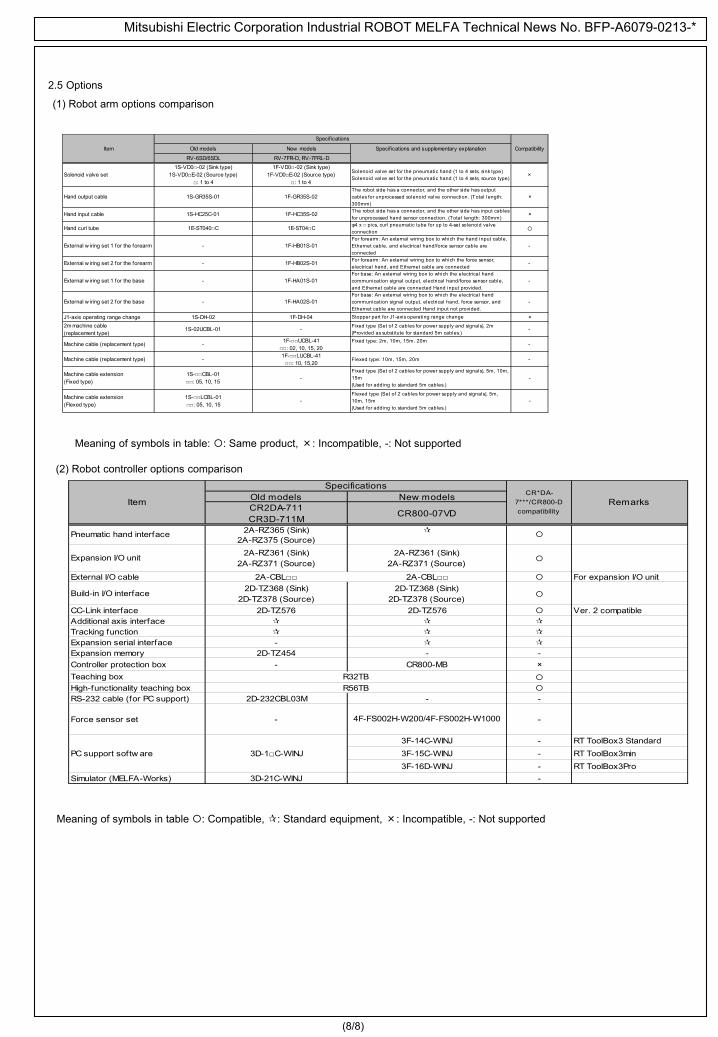
Meaning of symbols in table : Compatible, : Standard equipment, ×: Incompatible, -: Not supported
(2) Robot controller options comparison
Old models New modelsCR2DA-711CR3D-711M
CR800-07VD
2A-RZ365 (Sink) 2A-RZ375 (Source)
Expansion I/O unit 2A-RZ361 (Sink)2A-RZ371 (Source)
2A-RZ361 (Sink)2A-RZ371 (Source)
External I/O cable 2A-CBL 2A-CBL For expansion I/O unit
Build-in I/O interface 2D-TZ368 (Sink)2D-TZ378 (Source)
2D-TZ368 (Sink)2D-TZ378 (Source)
CC-Link interface 2D-TZ576 2D-TZ576 Ver. 2 compatibleAdditional axis interface Tracking function Expansion serial interface - Expansion memory 2D-TZ454 - -Controller protection box - ×Teaching box High-functionality teaching box RS-232 cable (for PC support) 2D-232CBL03M - -
Force sensor set - -
- RT ToolBox3 Standard- RT ToolBox3min- RT ToolBox3Pro
Simulator (MELFA-Works) 3D-21C-WINJ -
4F-FS002H-W200/4F-FS002H-W1000
PC support softw are 3D-1C-WINJ3F-14C-WINJ3F-15C-WINJ3F-16D-WINJ
Pneumatic hand interface
Specifications
R32TB
CR*DA-7***/CR800-Dcompatibility
Item
R56TB
Remarks
CR800-MB
Meaning of symbols in table: : Same product, ×: Incompatible, -: Not supported
(1) Robot arm options comparison
2.5 Options
Old models New models Specif ications and supplementary explanation
RV-6SD/6SDL RV-7FR-D, RV-7FRL-D
Solenoid valve set1S-VD0-02 (Sink type)
1S-VD0E-02 (Source type): 1 to 4
1F-VD0-02 (Sink type)1F-VD0E-02 (Source type)
: 1 to 4
Solenoid valve set for the pneumatic hand (1 to 4 sets, sink type)Solenoid valve set for the pneumatic hand (1 to 4 sets, source type)
×
Hand output cable 1S-GR35S-01 1F-GR35S-02The robot side has a connector, and the other side has outputcables for unprocessed solenoid valve connection. (Total length:300mm)
×
Hand input cable 1S-HC25C-01 1F-HC35S-02 The robot side has a connector, and the other side has input cablesfor unprocessed hand sensor connection. (Total length: 300mm)
×
Hand curl tube 1E-ST040C 1E-ST04C φ4 x pics, curl pneumatic tube for up to 4-set solenoid valveconnection
External w iring set 1 for the forearm - 1F-HB01S-01For forearm: An external wiring box to which the hand input cable,Ethernet cable, and electrical hand/force sensor cable areconnected
-
External w iring set 2 for the forearm - 1F-HB02S-01 For forearm: An external wiring box to which the force sensor,electrical hand, and Ethernet cable are connected
-
External w iring set 1 for the base - 1F-HA01S-01For base: An external wiring box to which the electrical handcommunication signal output, electrical hand/force sensor cable,and Ethernet cable are connected Hand input provided.
-
External w iring set 2 for the base - 1F-HA02S-01For base: An external wiring box to which the electrical handcommunication signal output, electrical hand, force sensor, andEthernet cable are connected Hand input not provided.
-
J1-axis operating range change 1S-DH-02 1F-DH-04 Stopper part for J1-axis operating range change ×2m machine cable(replacement type)
1S-02UCBL-01 - Fixed type (Set of 2 cables for power supply and signals), 2m(Provided as substitute for standard 5m cables.)
-
Machine cable (replacement type) - 1F-UCBL-41: 02, 10, 15, 20
Fixed type: 2m, 10m, 15m. 20m -
Machine cable (replacement type) - 1F-LUCBL-41: 10, 15,20
Flexed type: 10m, 15m, 20m -
Specif ications
Fixed type (Set of 2 cables for power supply and signals), 5m, 10m,15m(Used for adding to standard 5m cables.)
Flexed type (Set of 2 cables for power supply and signals), 5m,10m, 15m(Used for adding to standard 5m cables.)
Machine cable extension(Fixed type)
1S-CBL-01: 05, 10, 15 -
Machine cable extension(Flexed type)
1S-LCBL-01: 05, 10, 15
-
Item
-
-
Compatibility

Mitsubishi Electric Corporation Industrial ROBOT MELFA Technical News No. BFP-A6079-0213-*
The following table provides compatibility between old and new models.3.1 Compatibility of the robot arm
3. Compatibility
3.2 Compatibility of the controllerSpecificationsOld models New modelCR2DA-711CR3D-711M
CR800-07VD
TB High-functionality TB I/O map 0 to 9999 0 to 9999 Programming language MELFA-BASIC V MELFA-BASIC VI ×PC support software RT ToolBox2 RT ToolBox3 ×
Maintenance Backup battery Q6BAT - ×
CompatibilityRemarks
R32TBR56TB
Category Item
Operation
(8/8)
3.3 Precautions of the extension function for GOT direct connection
The start addresses of the GOT shared memory (CPU buffer memory) I/O are different between old and new models.
Precautions of controller specifications
GOT output start address (to robot)Robot input signal start addressRobot output signal start addressGOT input start address (from robot)Memory configuration
Item FR series
100001000010000
Shared memory among GOTs CPU buffer memoryU3E1\G10000 U3E1\HG0
U3E0\G10000
RemarksOld models
CR2DA-711/CR3D-711M CR800-07VD
10000
Specifications
U3E0\G0
Robot language
Serial number of robot
Origin setting
Hand type
Mode selector input
Enabling device switch inputBattery
TB dummy connector
ItemFR series
Necessary to input (by using the T/B or RT2)Not necessary to input
(The data has been stored in the robot's internal ROM.)
NecessaryNot necessary
After deadman turns on, the T/B can be removed withoutstopping the robot even during operation.
Necessary to input (by using the T/B or RT2)Not necessary to input
(The data has been stored in the robot's internal ROM.)
MELFA-BASIC IVMELFA-BASIC V
Provided (Q6BAT, 1pc.)
Old modelsCR2DA-711/CR3D-711M
CR800-07VD
Specifications
MELFA-BASIC IV cannot be used directly.(RT3 converts MELFA-BASIC IV into MELFA-BASIC V or VI.)
MELFA-BASIC VMELFA-BASIC VI (upper-compatible of MELFA-BASIC V)
*In MELFA-BASIC VI, the description method of program isthe same as MELFA-BASIC V unless the Function or
Include commands are used.
Not using (Not necessary to replace the battery)
Sink type (initial value)It is necessary to set a parameter for
selecting the source type.
Not set (initial value)It is necessary to select either sink or source type by setting
a parameter.(If not set, an error will occur.)
Provided
Provided(Customer needs to prepare a mode selector switch)
Recommended key switch: HA1K-2C2A-2 (manufactured by IDEC)
Provided Not provided
Category Item
Specifications
Compatibility RemarksOld models New models
RV-6SD/6SDL RV-7F-D/RV-7FL-D
Outside dimensions
Installation dimensions Changed × Base width dimension is incompatible.
Mechanical interface Changed Compatible, however, note that the screw depth and hole depth are changed.
Operating range Changed
Compatible if the operating range of the old model is within that of the new model under a standard use condition. However, when the old model is used in the reverse operating range, check if this range can be replaced with the operating range of the new model.
ToolingHand wiring Changed × IncompatibleHand piping No change
Backup wiring Changed ×
Maintenance Backup battery A6BAT MR-BAT6V1 ×
Meaning of symbols in table : Fully compatible, ×: Incompatible, : Partially compatible