Embed Size (px)
Citation preview

MegaRUM II
Dual Pentium II®
PCI ISA MotherboardUser's Guide
MAN-7741/15/99

MegaRUM II PCI Motherboard User’s Guideii
© Copyright 1985-2010 American Megatrends, Inc.All rights reserved.American Megatrends, Inc.5555 Oakbrook Parkway, Building 200,Norcross, GA 30093
This publication contains proprietary information which is protected by copyright. No part of this publication maybe reproduced, transcribed, stored in a retrieval system, translated into any language or computer language, ortransmitted in any form whatsoever without the prior written consent of the publisher, American Megatrends, Inc.
Limited Warranty
Buyer agrees if this product proves to be defective, that American Megatrends, Inc. is only obligated to replace orrefund the purchase price of this product at American Megatrend's discretion according to the terms and conditionson the motherboard warranty card. American Megatrends shall not be liable in tort or contract for any loss ordamage, direct, incidental or consequential. Please see the Warranty Registration Card shipped with this productfor full warranty details.
Limitations of Liability
In no event shall American Megatrends be held liable for any loss, expenses, or damages of any kind whatsoever,whether direct, indirect, incidental, or consequential, arising from the design or use of this product or the supportmaterials provided with the product.
Trademarks
VESA is a registered trademark of the Video Electronics Standards Association.Intel, Pentium. Pentium Pro, and Pentium II are registered trademarks of Intel Corporation.MS-DOS, Microsoft Word, and Microsoft are registered trademarks of Microsoft Corporation.Microsoft Windows, Windows NT, and Windows 95 are trademarks of Microsoft Corporation.IBM, AT, XT, CGA, VGA, PS/2, OS/2, and EGA are registered trademarks of InternationalBusiness Machines Corporation.Fujitsu is a registered trademark of Fujitsu America, Inc.Motorola is a registered trademark of Motorola Corporation.Hitachi is a registered trademark of Hitachi America, Ltd.PNY is a registered trademark of PNY Corporation.Oki is a registered trademark of Oki America, Inc.NEC is a registered trademark of NEC Corporation.Micron is a registered trademark of Micron Corporation.SCO, Unix, and UnixWare are registered trademarks of the Santa Cruz Operation, Inc.Toshiba is a registered trademark of Kabushiki Kaisha Toshiba.All other brand and product names are trademarks or registered trademarks of their respectivecompanies.
Revision History
5/1/98 Initial release of preliminary version.5/12/98 Revised AMIBIOS Setup chapter.8/5/98 Revised motherboard drawing for Rev C.9/4/98 Released revised manual.9/24/98 Revised motherboard drawing and printed addendum.11/6/98 Added Chapter 5, about AMI ClientCare installation12/11/98 Removed references to DMI Wizard 95. Replace SystemGuru with AMI_ClientCare.1/15/99 Deleted Xeon and added Pentium II.

Preface iii
Table of Contents
1 Hardware Installation....................................1MegaRUM II PCI Motherboard Layout ..........................3Step 1 Unpack the Motherboard .....................................4Step 2 Configure CPU Speed..........................................5Step 3 Install Additional Voltage Regulator ...................6Step 4 Connect CPU Fans ..............................................6Step 5 Install CPU..........................................................7Step 6 Install Memory ..................................................12Step 7 Install the Motherboard .....................................14Step 8 Attach Cables ....................................................15Step 9 Connect I/O.......................................................23Step 10 Connect SCSI I/O............................................32Step 11 Install Drivers..................................................37Step 12 Test and Configure ..........................................38
2 AMIBIOS Setup............................................39Section 1 Standard Setup .....................................................41Section 2 Advanced CMOS Setup........................................46Section 3 Advanced Chipset Setup.......................................50Section 4 Power Management Setup....................................52Section 5 PCI/PnP Setup......................................................56Section 6 Peripheral Setup...................................................62Section 7 Other Setup Options.............................................66
Auto-Detect Hard Disks ...............................................66AMIBIOS Password Support........................................66Change User Password.................................................67Change Supervisor Password........................................67Change Language Settings ...........................................67Auto Configuration with Optimal Settings ...................68Auto Configuration with FailSafe Settings ...................68Save Settings and Exit..................................................68Exit Without Saving.....................................................68
3 Programming Flash ROM...........................71
4 Deleting a Password...................................75
5 AMI_ClientCare Installation Procedure .....77
A Specifications..............................................79
Index...................................................................81

MegaRUM II PCI Motherboard User’s Guideiv
Preface
To the OEM Thank you for purchasing the high performance AmericanMegatrends MegaRUM II Dual Pentium II PCI ISAmotherboard. This product is a state of the artmotherboard that includes the famous AMIBIOS. It isassumed that you have also licensed the rights to use theAmerican Megatrends documentation for the AmericanMegatrends MegaRUM II motherboard.
This manual was written for the OEM to assist in theproper installation and operation of this motherboard.This manual describes the specifications and features ofthe MegaRUM II PCI motherboard. It explains how toassemble a system based on the MegaRUM II PCImotherboard and how to use the AMIBIOS that isspecifically designed for this motherboard.
This manual is not meant to be read by the computerowner who purchases a computer with this motherboard.It is assumed that you, the computer manufacturer, willuse this manual as a sourcebook of information, and thatparts of this manual will be included in the computerowner's manual.
Disclaimer
AMI only certifies that this product will work correctly when thisproduct is used with the same jumper settings, the same system
configuration, the same memory module parts, and the sameperipherals that were tested by AMI with this product. The complete
list of tested jumper settings, system configurations, peripheraldevices, and memory modules are documented in the AMICompatibility Report for this product. Call your AMI sales
representative for a copy of the Compatibility Report for this product.
Technical Support If an American Megatrends motherboard fails tooperate as described or you are in doubt about aconfiguration option, please call technical support at 770-246-8600.
Web Site We invite you to access the American Megatrends worldwide web site at:
http://www.ami.com.

Preface v

MegaRUM II PCI Motherboard User’s Guidevi
Packing List
You should have received the following:
• a MegaRUM II Dual Pentium II PCI ISAmotherboard,
• one SCSI driver diskette,• the AMI Server Manager User’s Guide,• one CD containing the AMI Server Manager server
management software for Windows NT,• one termination card,• two VRM modules,• two retention mechanisms for the Pentium II CPUs,• two plastic spacers for the Pentium II retention
mechanisms,• a Warranty Card, and• the American Megatrends MegaRUM II Dual
Pentium II PCI ISA Motherboard User's Guide.

Preface vii


Chapter 1 Hardware Installation 1
1 Hardware InstallationOverview
The American Megatrends MegaRUM II PCI DualPentium II ISA motherboard features include:
• two Intel Pentium II CPUs operating at 120, 133,150, 166, 180, 200, 210, 233, 240, 266, 300, 333, 400MHz or higher speeds ,
• up to 2 GB of system memory (512 MB has beentested) on the motherboard,
• parity checking or ECC (Error Checking andCorrection),
• PCI local bus throughput of 132 megabytes persecond,
• two Ultra Wide SCSI channels operating at 80 MB/s,• specially designed for the American Megatrends
RAID Upgrade controller cards,• the American Megatrends AMI_ClientCare server
management software,• one ISA expansion slot,• four 32-bit PCI expansion slots, and• two 64-bit PCI expansion slots.
CPUs The MegaRUM II motherboard will support all Intel Slot1CPUs operating at 233 MHz, 266 MHz, 400 MHz orfaster speeds.
PCI Bus Speed AMIBIOS automatically configures the PCI slots. ThePCI slots are synchronous with the CPU clock:
CPU External Clock Frequency PCI Expansion Slot Frequency100 MHz 33 MHz66 MHz 33 MHz
Cont’d

MegaRUM II PCI Motherboard User’s Guide2
Overview, Continued
Onboard I/O The MegaRUM II motherboard includes:
• one onboard Symbios Logic 53C896 SCSI controllerthat provides two 80 MB/s ultra wide SCSI channels,
• two 40-pin IDE connectors for 1 – 4 IDE drives,• a 34-pin floppy drive connector,• two serial port connectors,• a 25-pin parallel port connector,• a keyboard DIN connector,• two 4-pin USB ports, and• a 9-pin berg keyboard/mouse connector.
Server Management Software The American MegatrendsAMI_ClientCare server management software is includedwith the MegaRUM II motherboard. AMI_ClientCareuses the I2C interface to constantly monitor and report theCPU temperature, fan speed, ECC memory errors,ambient temperature, CPU voltage, system voltage andother user-specified system status information to anyremote client computer. See the American MegatrendsAMI_ClientCare User’s Guide for additional information.

Chapter 1 Hardware Installation 3
MegaRUM II PCI Motherboard Layout

MegaRUM II PCI Motherboard User’s Guide4
Step 1 Unpack the Motherboard
Step Action1 Inspect the cardboard carton for obvious damage. If damaged, call 770-
246-8600. Leave the motherboard in its original packing.2 Perform all unpacking and installation procedures on a ground-
connected anti-static mat. Wear an anti-static wristband grounded atthe same point as the anti-static mat. Or use a sheet of conductivealuminum foil grounded through a 1 megohm resistor instead of theanti-static mat. Similarly, a strip of conductive aluminum foil wrappedaround the wrist and grounded through a 1 megohm resistor serves thesame purpose as the wristband.
3 Inside the carton, the motherboard is packed in an anti-static bag, andsandwiched between sheets of sponge. Remove the sponge and theanti-static bag. Place the motherboard on a grounded anti-static surfacecomponent side up. Save the original packing material.
4 Inspect the motherboard for damage. Press down on all ICs mounted insockets to verify proper seating. Do not apply power to themotherboard if it has been damaged.
5 If the motherboard is undamaged, it is ready to be installed.
Set Jumpers Set all jumpers and install the CPU before placing themotherboard in the chassis.
Avoid Static Electricity
Static electricity can damage the motherboard and othercomputer components. Keep the motherboard in the anti-static bag until it is to be installed. Wear an anti-staticwrist grounding strap before handling the motherboard.Make sure you stand on an anti-static mat when handlingthe motherboard.
Avoid contact with any component or connector on anyadapter card, printed circuit board, or memory module.Handle these components by the mounting bracket.

Chapter 1 Hardware Installation 5
Step 2 Configure CPU Speed
If using two CPUs with different speed ratings, set themotherboard jumpers to the lower CPU speed. When JP6is open, the system bus frequency is determined by theprocessors. When JP6 is shorted, the system bus frequencyis forced to be 66 MHz.
ImportantPlease contact American Megatrends technical support
at 770-246-8600 to support a CPU running at otherspeeds.
CPU InternalFrequency if Bus
Frequency is 100 MHz
CPU InternalFrequency if Bus
Frequency is 66 MHz
JP8
350 MHz 233 MHz Short Pins 1-2Open Pins 3-4Open Pins 5-6Short Pins 7-8
400 MHz 266 MHz Open Pins 1-2Short Pins 3-4Short Pins 5-6Short Pins 7-8
450 MHz 300 MHz Open Pins 1-2Short Pins 3-4Open Pins 5-6Short Pins 7-8
500 MHz 330 MHz Open Pins 1-2Open Pins 3-4Short Pins 5-6Short Pins 7-8
Cont’d

MegaRUM II PCI Motherboard User’s Guide6
Step 3 Install Additional Voltage Regulator
One Voltage Regulator Module (VRM) is shipped withevery MegaRUM II motherboard. You need another VRMif you install two CPUs. You can order VRMs for IntelPentium II CPUs from:
Manufacturer Part Number AMI Part NumberVXI 073-20740-20 MDL-PII-V5A190
Step 4 Connect CPU Fans
JP1 and JP2 (shown below) are 3-pin bergs that connectthe fan on the CPU heat sink to the motherboard power.JP1 is the CPU fan connector for the CPU in CPU Slot1.JP2 is the CPU fan connector for the CPU in CPU Slot2.
All Pentium II CPUs are shipped with a heat sink and aCPU fan.
JP1 and JP2 are keyed in such a way that the CPU fanconnector can only be attached in the correct manner.
The connector from the CPU fan usually has three leads(red, yellow, and black leads).
JP19, JP18 System Fan JP19and JP18 are 3-pin bergs. The pinout is thesame for JP19 and JP18 as it is for JP1 and JP2. JP19 andJP18 provide +12V power to the main chassis fan. Thechassis fan should provide a tachometer output on Pin 3so it can be monitored by the onboard server managementhardware.

Chapter 1 Hardware Installation 7
Step 5 Install CPU
The Pentium II CPUs are on Intel Slot1 adapter cards.Insert the Slot1 cards into the CPU card sockets on themotherboard. See the motherboard drawing on page 3 forthe location.
The CPU Slot1 sockets are below the SDRAM sockets, asshown on page 3.
Warning
Improper CPU installation can damage the CPU and themotherboard. You must follow the procedures in this
section exactly as documented. Make sure you wear anantistatic wristband while installing the CPU. Follow all
antistatic procedures described on page 4.
Termination Card The MegaRUM II motherboard is shipped with atermination card that should be installed in the emptyCPU slot if only one CPU is installed.
You must install the termination card in the empty CPUslot if installing only one Pentium II CPU. Themotherboard will not power up unless both CPU slots areoccupied. The CPU slot where the termination card isinstalled does not require a VRM.
Cont’d

MegaRUM II PCI Motherboard User’s Guide8
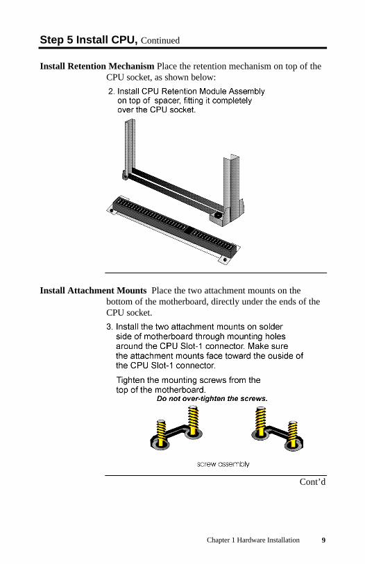
Step 5 Install CPU, Continued
Retention Mechanism Kit You must mount the Intel RetentionMechanism Kit before installing all Pentium II CPUmodules. This kit includes: the retention mechanismassembly, attachment mounts, and spacer, as shownbelow:
Install Spacer Place the spacer around the CPU socket on themotherboard, as shown below:
Cont’d
Chapter 1 Hardware Installation 9
Step 5 Install CPU, Continued
Install Retention Mechanism Place the retention mechanism on top of theCPU socket, as shown below:
Install Attachment Mounts Place the two attachment mounts on thebottom of the motherboard, directly under the ends of theCPU socket.
Cont’d

MegaRUM II PCI Motherboard User’s Guide10
Step 5 Install CPU, Continued
Install the Heat Sink If the heat sink is not already installed on the CPUmodule, slide the heat sink top support into the lowest gapon the CPU module, as shown below:
The slide the CPU module into the Retention MechanismAssembly, as shown below:
Cont’d

Chapter 1 Hardware Installation 11
Step 5 Install CPU, Continued
Install the Heat Sink, cont’d Press the buttons on either side of the CPUmodule, as shown below:
Hook the top support of the heat sink to the support baseof the heat sink to complete the CPU module installation:

MegaRUM II PCI Motherboard User’s Guide12
Step 6 Install Memory
System Memory There are four 72-bit SDRAM DIMM (Dual InlineMemory Module) sockets. System memory must bepopulated one bank at a time. Each bank has one socket.
The minimum amount of system memory supported by theMegaRUM II PCI is 8 MB. Each socket can hold oneDIMM. You can use:
• 1 MB x 64 (or 72),• 2 MB x 64 (or 72),• 4 MB x 64 (or 72),• 8 MB x 64 (or 72),• 16 MB x 64 (or 72),• 32 MB x 64 (or 72), or• 64 MB x 64 (or 72).
Fast Page Mode and EDO SIMMs cannot be mixed inthe same memory bank.
The MegaRUM II motherboard will support 128 MBSIMMs when they become available, permitting up to 2GB of system memory to be installed on the motherboard.The motherboard supports SDRAM DIMM operating at10 or 12 ns (RAS access time).
Memory Display System memory is reported by AMIBIOS as it boots andagain when the AMIBIOS System Configuration Screen isdisplayed just before the operating system boots. Thememory displayed by AMIBIOS on the SystemConfiguration Screen is 384 KB less than the totalmemory installed.
PC 100 Compatible Specifications
Parameter Specification100 MHz Unbuffered SDRAM DIMM
Cont’d

Chapter 1 Hardware Installation 13
Step 6 Install Memory, Continued
Installing DIMMs The eight SDRAM DIMM sockets on the motherboardcan be filled with either 1 MB x 64 (or 72), 2 MB x 64 (or72), 4 MB x 64 (or 72), 8 MB x 64 (or 72), or 16 MB x 64(or 72) DIMMs.
Place the motherboard on an anti-static mat. With thecomponent side of the DIMM facing you, firmly push theDIMM into the socket at an angle, then push it up. Whenproperly inserted, the DIMM clicks into place as thelatching pins engage. The DIMM installation process isshown below:
Title: INSSIMM.EPS from CorelDRAW!Creator: CorelDRAW!CreationDate: Mon Jul 10 10:35:32 1995

MegaRUM II PCI Motherboard User’s Guide14
Step 7 Install the Motherboard
Step Action1 Place the chassis on an anti-static mat. Connect the chassis to ground
to avoid static damage during installation. Connect an alligator clipwith a wire lead to any unpainted part of the chassis. Ground the otherend of the lead at the same point as the mat and the wristband.
2 Rotate the chassis so the front is to the right, and the rear is to the left.The side facing you is where the motherboard is mounted. The powersupply is mounted at the far end of the chassis.
3 Hold the motherboard, component-side up, with the edge with theSIMM sockets toward you and the edge with the power supplyconnector away from you. The keyboard, mouse, and video connectorsshould be to the left.
4 Carefully slide the motherboard into the chassis. Make certain the edgeconnectors fit the ports in the rear of the chassis. The motherboardshould rest level with the chassis.
5 Place the mounting screws in the holes provided and tighten them. Ifnecessary, shift the motherboard slightly to align the mounting holes onthe motherboard with the holes on the chassis,
Warning
If using metallic screws, make sure you use them only inthe plated mounting holes.
If using metallic screws, make sure the head of the screwfits completely inside the plated mounting holes.

Chapter 1 Hardware Installation 15
Step 8 Attach Cables
Connectors The MegaRUM II PCI motherboard includes manyconnectors. Connection instructions, illustrations ofconnectors, and pinouts are supplied in the followingpages. A list of all connectors described in this sectionfollows:
Connector turn toPower supply connectors JP7, JP10 page 17Drain CMOS RAM power – JP11 page 18Infrared connector – JP3 page 18Keyboard connector J2 page 19PS/2 mouse connector J1 page 19Chassis intrusion LED – JP13 page 19Hardware reset switch JP17 page 20Speaker JP20 page 20BIOS chip voltage select JP15 page 20Keyboard lock connector J15 page 21USB connector J3 page 22BIOS size select jumper JP14 page 22Power Button JP16 page 22Serial port 1 connector J6 page 23Serial port 2 connector J7 page 23Parallel port connector J5 page 24Floppy connector JP9 page 25IDE primary connector JP5 page 28IDE secondary connector JP4 page 29RAC – Port J9 page 31SCSI channel 1 (Wide) – J18 page 32SCSI channel 2 (Wide) – J17 page 32
Cont’d

MegaRUM II PCI Motherboard User’s Guide16
Step 8 Attach Cables, Continued
Cable Connector Ends When connecting chassis connectors to themotherboard, make sure to connect the correct connectorend. Most connector wires are color-coded. Match thecolor of the wires leaving the switch or LED to the samepin on the connector end. There may be more than oneconnector with the same color-coded wires. If so, followthe wire to the switch or LED. All motherboardcomponents are outlined by a white rectangular box with abroad arrow at one end. Pin 1 is always at the arrow endof the white outlined box, as shown below:
Cont’d

Chapter 1 Hardware Installation 17
Step 8 Attach Cables, Continued
Connect Power Supply The power supply should match the physicalconfiguration of the chassis. Make sure the power switchis Off before assembly.
Before attaching all components, make sure the propervoltage has been selected. Power supplies often can run ona wide range of voltages and must be set (usually via aswitch) to the proper range. Use at least a 300 watt powersupply, which should have built-in filters to suppressradiated emissions.
Attach the power supply cables to the power connector onthe motherboard. ATX-compatible power supplies havetwo 20-pin connectors, JP7 and JP10. The powerconnector pinout is:
Pin Description Pin Description11 +3.3V 1 +3.3V12 -12V 2 +3.3V13 Ground 3 Ground14 -PWR_ON 4 +5V15 Ground 5 Ground16 Ground 6 +5V17 Ground 7 Ground18 -5V 8 PWR+GOOD19 +5V 9 5V_VR20 +5V 10 +12V
Cont’d

MegaRUM II PCI Motherboard User’s Guide18
Step 8 Attach Cables, Continued
JP11 Drain CMOS RAM Power JP11 is a 3-pin berg that can be used toerase the contents of CMOS RAM, where all systemconfiguration information is stored.
If you forget the AMIBIOS password, you can place ashorting bridge on JP11 for a few seconds to erase the oldpassword (and all system configuration information aswell). You must then reboot the computer, run AMIBIOSSetup, and restore all system configuration information.The JP11 settings are:
CMOS Drain JP SettingNormal operation (factory setting). 1-2
The contents of CMOS RAM are destroyed. 2-3
JP3 Infrared Connector The JP3 is a 10-pin dual-inline berg.
Pin Assignments1 VCC5V
2, 6, 7, 8, 9, 10 N/C345
IRRXGNDIRTX
Cont’d

Chapter 1 Hardware Installation 19
Step 8 Attach Cables, Continued
J2 Keyboard Connector The keyboard connector is a 9-pin MINIDINsocket. The pinout is shown below.
Pin Assignments1 Keyboard data
2, 6, 9 Not used3 KBGGND4 VCC5 Keyboard clock
7 – 8 Ground
Connect Mouse Cable The mouse connector is a 9-pin MINIDIN. Thepinout is:
Pin Description Pin Description1 Mouse data 2, 6, 9 N/C3 Keyboard ground 4 VCC5 Mouse clock 7, 8 Ground
JP13 Chassis Door Intrusion JP13 is a 2-pin berg that can be used toattach a wire to the chassis door intrusion connector, if thechassis has this feature. The logic must be set so that Pin1 and Pin 2 are shorted when the chassis door is closedand open when the chassis door is opened.
Cont’d

MegaRUM II PCI Motherboard User’s Guide20
Step 8 Attach Cables, Continued
JP17 Reset Switch Connector JP17 is a two-pin berg that is attached via acable to an externally-mounted reset switch. When thereset switch is pressed, the system performs a hard reset.Pin 2 is ground and Pin 1 is Hard Reset.
JP20 Speaker Connector JP20 is a four-pin single-inline berg that isoptionally attached via a cable to a standard speaker.AMIBIOS signals hardware problems through thespeaker.
Pin Description1 VCC2 N/C3 N/C4 Data out
JP15 BIOS Chip Voltage Select JP15 is a 3-pin single-inline berg whichlets you choose the BIOS chip VPP voltage.
Pin DescriptionShort pin 1-2 VPP = 12V (default)Short pin 2-3 VPP = 5V
Cont’d

Chapter 1 Hardware Installation 21
Step 8 Attach Cables, Continued
J15 Keyboard Lock J15 is a 5-pin single-inline berg that is attached via acable to the keyboard lock connector (or separate keyboardlock and Power LED connectors). The computer chassismay not include the keyboard lock and Power LED on asingle connector. The keyboard lock allows the user tolock the keyboard, protecting the system fromunauthorized use. Pin 1 on the motherboard is identifiedby the broad arrow.
Pin Description1 VCC2 Ground3 Ground4 Keyboard Lock (KBDINH)5 Ground
Cont’d

MegaRUM II PCI Motherboard User’s Guide22
Step 8 Attach Cables, Continued
Optional USB Cable You can only use a custom USB cable with thismotherboard. You can order this USB cable (AMI partnumber CBLKIT-USB-1) from American Megatrends at800-828-9264.
WarningThe pinout for the optional USB Cable Box is:
Pin 1 Red VCCPin 2 Green Data +Pin 3 White Data -Pin 4 Black GroundPlease make sure that the USB cable is correctly installed. Incorrect
installation will damage the motherboard.
J3 USB Connectors J3 is 4-pin USB (Universal Serial Bus) stackedconnector. The pinouts are:
Pin Signal Description1 VCC2 Data+3 Data–4 Ground
JP14 BIOS Size Select JP14 is a 3-pin berg that enables you to choose theBIOS size.
Pin DescriptionShort pin 1-2 BIOS size = 256KB (default)Short pin 2-3 BIOS size = 128KB
JP16 Power Button JP16 is a two-pin single-inline berg.
Cont’d

Chapter 1 Hardware Installation 23
Step 9 Connect I/O
Onboard Adapters The MegaRUM II PCI motherboard has:
• two serial ports (J6 and J7),• a parallel port (J5),• two Ultra Wide SCSI connectors,• an IDE controller on the PCI bus (the primary IDE
connector is JP5 and the secondary IDE connector isJP4), and
• a floppy controller (JP9).
The serial and parallel port connectors are describedbelow.
Conflicts AMIBIOS minimizes conflicts between onboard andoffboard I/O devices.
AMIBIOS automatically checks the adapter cardsinstalled in the expansion slots on the MegaRUM II PCImotherboard for a hard disk or floppy controller and serialor parallel ports.
J6 SER1 J7 SER2 J6 and J7 are 9-pin connectors that provide an AT-compatible serial port interface. Connect the cablessupplied with the motherboard to J6 and J7. The serialport base I/O port address and other serial port settingscan be selected in Peripheral Setup in AMIBIOS® Setup.
The J6 and J7 pinout is shown below.
Pin Signal Description Pin Signal Description1 Carrier Detect 6 Data Set Ready2 Receive Data 7 Request to Send3 Transmit Data 8 Clear to Send4 Data Terminal
Ready9 Ring Indicator
5 Ground 10 CUT PIN
Cont’d

MegaRUM II PCI Motherboard User’s Guide24
Step 9 Connect I/O, Continued
J5 Parallel Port J5 is a 25-pin connector for a parallel port. The J5 pinoutis shown below. Connect the 16-pin to DB25 cableprovided with the motherboard to J5. The parallel portinterface supports:
• the standard Centronics-compatible parallel port,• the ECP (Extended Capabilities Port), and• the EPP (Enhanced Parallel Port) port.
All parallel port settings must be correctly configuredthrough Peripheral Setup in AMIBIOS Setup.
Pin Signal Description Pin Signal Description1 STROBE# 2 PD03 PD1 4 PD25 PD3 6 PD47 PD5 8 PD69 PD7 10 ACK#11 BUSY 12 PE13 SLCT 14 AUTOFD#15 ERROR# 16 INIT#17 SLCTIN# 18 Ground19 Ground 20 Ground21 Ground 22 Ground23 Ground 24 Ground25 Ground 26 Ground
Cont’d

Chapter 1 Hardware Installation 25
Step 9 Connect I/O, Continued
JP9 Floppy JP9 is a 34-pin dual-inline berg. Connect the cable fromthe floppy drive to JP9, as shown below. The onboardfloppy controller cannot be used if a hard disk card with afloppy controller is installed. Choose Standard Setup andPeripheral Setup to configure the floppy controller.
The motherboard supports up to two 720 KB, 1.44 MB, or2.88 MB 3½" drives and 360 KB and 1.2 MB 5¼" drives.The connecting cable is a 34-pin ribbon connector withtwo 34-pin edge connectors for attaching the floppy diskdrives. There is a small twist in the cable between thefloppy connectors. The last (end) connector should beconnected to floppy drive A: as shown below.
Title: FLOOP.EPS from CorelDRAW!Creator: CorelDRAW!CreationDate: Tue Jun 06 17:57:03 1995
Cont’d

MegaRUM II PCI Motherboard User’s Guide26
Step 9 Connect I/O, Continued
JP9 Floppy Connector Pinout
Pin Use Pin Use1 GND 2 DENSE13 GND 4 N/C5 GND 6 DRATE07 GND 8 -INDEX9 GND 10 -MOTOR011 GND 12 -FDSEL113 GND 14 -FDSEL015 GND 16 -MOTOR117 GND 18 DIR19 GND 20 -21 GND 22 -WDATA23 GND 24 -WGATE25 GND 26 -TRK027 GND 28 -WRPROT29 GND 30 -RDATA31 GND 32 HDSEL33 GND 34 DSKCHNG
Twist in Floppy Cable
Floppy B to A Floppy B to A Floppy B to A Floppy B to A10 to 16 12 to 14 14 to 12 16 to 1011 to 15 13 to 13 15 to 11
Cont’d

Chapter 1 Hardware Installation 27
Step 9 Connect I/O, Continued
IDE Drives Attach the IDE drives in the following manner. ChoosePeripheral Setup in AMIBIOS Setup to enable theonboard IDE controller.
Cont’d

MegaRUM II PCI Motherboard User’s Guide28
Step 9 Connect I/O, Continued
Attach IDE Cable to JP5 JP5 is the primary IDE (Integrated DriveElectronics) hard disk drive connector. Both the primarymaster and the primary slave IDE drives must beconnected by cable to JP5, as shown below.
JP5 is a 40-pin dual-inline berg that connects an IDEdrive to the primary onboard IDE connector. Thismotherboard supports IDE Modes 0, 1, 2, 3, and 4, IDEprefetch, LBA (Logical Block Address) mode, highcapacity drives (over 528 MB), 32-bit data transfer, andfast IDE transfer. These IDE features are configured inPeripheral Setup in the AMIBIOS Setup utility.
Disable the onboard IDE interface in Peripheral Setup touse an ISA ESDI, RLL, MFM, or SCSI hard disk drivecontroller.
Cont’d

Chapter 1 Hardware Installation 29
Step 9 Connect I/O, Continued
JP5 Pinout JP5 is the primary IDE connector. The JP5 pinout is:
Pin Use Pin Use1 -RESET 2 GND3 DATA7 4 DATA85 DATA6 6 DATA97 DATA5 8 DATA109 DATA4 10 DATA11
11 DATA3 12 DATA1213 DATA2 14 DATA1315 DATA1 16 DATA1417 DATA0 18 DATA1519 GND 20 KEY (N/C)21 -REQ 22 GND23 -IOW 24 GND25 -IOR 26 GND27 IDERDY 28 Pulldown29 -ACK 30 GND31 INT14 32 N/C33 HA1 34 N/C35 HA0 36 HA237 -CS0 38 -CS139 -IDEACT 40 GND
JP4 Secondary IDE Controller JP4, the secondary IDE connector, is a 40-pin dual-inline berg that connects the secondary primaryand slave IDE drives to the secondary onboard IDEcontroller.
Attach the secondary master and slave IDE drives to JP4via a standard 40-pin IDE cable as shown on page 28.
Cont’d

MegaRUM II PCI Motherboard User’s Guide30
Step 9 Connect I/O, Continued
JP4 Pinout JP4 is the secondary IDE connector. The JP4 pinout is:
Pin Use Pin Use1 -RESET 2 GND3 DATA7 4 DATA85 DATA6 6 DATA97 DATA5 8 DATA109 DATA4 10 DATA11
11 DATA3 12 DATA1213 DATA2 14 DATA1315 DATA1 16 DATA1417 DATA0 18 DATA1519 GND 20 KEY (N/C)21 -REQ 22 GND23 -IOW 24 GND25 -IOR 26 GND27 IDERDY 28 Pulldown29 -ACK 30 GND31 INT15 32 N/C33 HA1 34 N/C35 HA0 36 HA237 -CS2 38 -CS339 N/C 40 GND
Cont’d

Chapter 1 Hardware Installation 31
Step 9 Connect I/O, Continued
J9 Pinout J9 is the 16-pin connector specifically for AMI’s newMegaRAC PCI adapter, which is a PCI remote assistantcard.
Pin Description12345678910111213141516
SMI#I2C CLKReservedGNDPower OffI2C DataReservedKeylockReservedReservedHSTRST#GNDGNDIRQ#GPI01GPI02

MegaRUM II PCI Motherboard User’s Guide32
Step 10 Connect SCSI I/O
SCSI Connectors J18 (SCSI channel 1) and J17 (SCSI channel 2) are 68-pin high density (Wide) SCSI connectors.
High Density SCSI Connectors The 68-pin high density connectors are0.050” pitch unshielded connectors. The high-densityconnector pinouts are shown below:
These connectors provide all signals needed to connect towide SCSI devices. The connector pinouts are for a single-ended primary bus (P-CABLE) as specified in SCSI-3Parallel Interface X3T9.2, Project 885-D, revision 1.2b,date July 2, 1993.
The cable assemblies that interface with this 68-pinconnector are:
• flat ribbon or twisted pair cable for connectinginternal wide SCSI devices,
• flat ribbon or twisted pair cable for connectinginternal and external wide SCSI devices,
• cable assembly for converting from internal wideSCSI connectors to internal non-wide (Type 2)connectors,
• cable assembly for converting from internal wide tointernal non-wide SCSI connectors (Type 30), and
• cable assembly for converting from internal wide tointernal non-wide SCSI connectors.
Cont’d

Chapter 1 Hardware Installation 33
Step 10 Connect SCSI I/O, Continued
High-Density 68-Pin SCSI Connector Pinout
Signal ConnectorPin
CablePin
CablePin
ConnectorPin
Signal
Ground Data12
1 1 2 35 -DB(12)
Ground Data13
2 3 4 36 -DB(13)
Data 14 3 5 6 37 -DB(14)Data 15 4 7 8 38 -DB(15)SCOP1 5 9 10 39 -DB(P1)Data 0 6 11 12 40 -DB(0)Data 1 7 13 14 41 -DB(1)Data 2 8 15 16 42 -DB(2)Data 3 9 17 18 43 -DB(3)Data 4 10 19 20 44 -DB(4)Data 5 11 21 22 45 -DB(5)Data 6 12 23 24 46 -DB(6)Data 7 13 25 26 47 -DB(7)Data (P) 14 27 28 48 -DB(P)Ground 15 29 30 49 GroundGroundDIFFSENS
16 31 32 50 Ground
TERMPWR 17 33 34 51 TERMPWRTERMPWR 18 35 36 52 TERMPWRReserved 19 37 38 53 ReservedGround 20 39 40 54 GroundATN 21 41 42 55 -ATNGround 22 43 44 56 GroundBSY 23 45 46 57 -BSYACK 24 47 48 58 -ACKRST 25 49 50 59 -RSTMSG 26 51 52 60 -MSGSEL 27 53 54 61 -SELC/D 28 55 56 62 -C/DREQ 29 57 58 63 -REQI/O 30 59 60 64 -I/OData 8 31 61 62 65 -DB(8)Data 9 32 63 64 66 -DB(9)Data 10 33 65 66 67 -DB(10)Data 11 34 67 68 68 -DB(11)
Cont’d

MegaRUM II PCI Motherboard User’s Guide34
Step 10 Connect SCSI I/O, Continued
Single-Ended Ultra SCSI Understanding the cable requirements,termination and stub lengths is key to the successfulimplementation of a Ultra-SCSI subsystem.
SCSI Cables - Up to Four Devices The total external SCSI cable lengthfor single-ended when using up to 4 Ultra-SCSI devices(maximum. capacitance of device = 25pf) should be lessthan or equal to:
(3 meter-(SCSI signal length on AMI RAID)-(SCSI length in storagebox)
= (3 meter - 0.305 meter - SCSI length in storage box)
= 2.695 - SCSI length in storage box
SCSI Cables - More than Four Devices The total external SCSI cablelength for single-ended when using from five to eightUltra-SCSI devices (max. cap of device = 25pf) should beless than or equal to:
(1.5 meter-(SCSI signal length on AMIRAID)-(SCSI length in storage box)
= (1.5 meter - 0.305 meter - SCSI length instorage box)
= 1.195 - SCSI length in storage box
Spacing Devices The SCSI devices should be uniformly spaced betweenterminators with the end devices located as close aspossible to the terminators.
SCSI Signal Path The SCSI signal path is a controlled impedanceenvironment with the following characteristic impedance:
90 ohms +/- 6 ohms for the REQ and ACKsignals
90 ohms +/- 10 ohms for all other signals
Cont’d

Chapter 1 Hardware Installation 35
Step 10 Connect SCSI I/O, Continued
SCSI Termination The SCSI channels on the MegaRUM II motherboarduse active termination for each SCSI channel. You mustterminate the SCSI bus properly. The SCSI bus on eachSCSI channel is an electrical transmission line and it mustbe terminated properly at both ends to minimizereflections and losses. You complete the SCSI bus bysetting termination at both ends.
Do not add terminators in the middle of the SCSI bus. Theend devices must be located as close as possible to theterminators. A simple rule is to place SCSI terminatorafter the last SCSI device on each of the SCSI connectors.MegaRUM II automatically terminates the onboard SCSIconnectors.
Stub length The stub length shall not exceed 0.1 meter. The spacing ofdevices on the SCSI bus should be at least three times thestub length to avoid stub clustering.
SCSI Cables Teflon flat ribbon cables give the best performance in theUltra-SCSI environment. These cables should be used forall internal cabling. To minimize discontinuities andsignal reflections, the use of cables with differentimpedance’s on the same bus should be minimized.
Cont’d

MegaRUM II PCI Motherboard User’s Guide36
Step 10 Connect SCSI I/O, Continued
SCSI Termination Possibilities
SCSIterminator
Termination on controllerdisabled
Termination on controllerenabled
SCSI devices(termination disabled on both)
Setup using one connector for one channel
Setup using two connectors for one channel
SCSI devices(termination disabled on both)SCSI devices
(termination disabled on both)
SCSIterminator
SCSIterminator
Termination onmotherboardenabled.
Termination onmotherboarddisabled.
If the MegaRUM II is at one end of a cable, it setstermination automatically at that end. Otherwise,MegaRUM II disables its own termination and you mustset termination at the cable ends. If another connector onMegaRUM II is also used for the same channel, thetermination on MegaRUM II is disabled automatically andtermination should be set on the device at the farthest endof the cable.
For a disk array, set SCSI bus termination so thatremoving or adding a SCSI device does not disturbtermination. An easy way to do this is to connectMegaRUM II at one end of the SCSI cable for eachchannel and to connect an external terminator module atthe other end of each cable. The connectors between thetwo ends can connect SCSI devices. Disable terminationon the SCSI devices. See the manual for each SCSI deviceto disable termination.
Selecting a SCSI Terminator Use ALT-2 type external SCSI terminatorson SCSI channels operating at 10 MB/s or highersynchronous data transfer.
Cont’d

Chapter 1 Hardware Installation 37
Step 11 Install Drivers
The following drivers are provided with the MegaRUM IImotherboard:
• one CD containing the American Megatrends AMI ServerManager server management software, and
• one diskette with SCSI drivers for Windows NT v3.51 andv4.0, and SCSI drivers for Windows 95.
Installing AMI Server Manager The American Megatrends AMI ServerManager User’s Guide is provided with the MegaRUM IImotherboard. Follow the installation instruction in theAmerican Megatrends AMI Server Manager User’sGuide.
Installing SCSI Drivers The SCSI driver installation process is operatingsystem-dependent. See the user documentation for theoperating system that is installed in this computer forinformation about the SCSI driver installation procedure.

MegaRUM II PCI Motherboard User’s Guide38
Step 12 Test and Configure
Review the following points before powering up:
• make sure that all adapter cards are seated properly,• make sure all connectors are properly installed,• make sure the CPU is seated properly,• make sure there are no screws or other foreign
material on the motherboard,• plug the system into a surge-protected power strip,
and• make sure blank back panels are installed on the back
of the chassis to minimize RF emissions.
Start the Test Plug everything in and turn on the switch. If there are anysigns of a problem, turn off the unit immediately.Reinstall the connectors. Call Technical Support if thereare problems.
BIOS Errors If the system operates normally, a display should appearon the monitor. The BIOS Power On Self Test (POST)should execute.
If POST does not run successfully, it will beep or displayerror messages. Beeps indicate a serious problem with thesystem configuration or hardware. The Beep Codeindicates the problem. AMIBIOS Beep Codes are definedin the AMIBIOS Technical Reference. Make sure theaffected part is properly seated and connected. An errormessage is displayed if the error is less serious. Recheckthe system configuration or the connections.
Configure the System Run AMIBIOS Setup. You must enter the requestedinformation and save the configuration data in NVRAM.The system will then reset, run POST, and boot theoperating system. See the following chapter forinformation on configuring the computer.

Chapter 2 AMIBIOS Setup 39
2 AMIBIOS SetupIn ISA and EISA computers, the system parameters (suchas amount of memory, type of disk drives and videodisplays, and many other elements) are stored in CMOSRAM. Unlike the DRAM (dynamic random accessmemory) that is used for standard system memory, CMOSRAM requires very little power. When the computer isturned off, a back-up battery provides power to CMOSRAM, which retains the system parameters. Every timethe computer is powered-on, the computer is configuredwith the values stored in CMOS RAM by the systemBIOS, which gains control when the computer is poweredon.
The system parameters are configured by a system BIOSSetup utility. Historically, BIOS Setup utilities have beencharacter-based, required keyboard input, and have haduser interfaces that were not very intuitive.
Starting AMIBIOS Setup As POST executes, the following appears:
Hit DEL if you want to run SETUP
Press Delete to run AMIBIOS Setup.

MegaRUM II PCI Motherboard User’s Guide40
AMIBIOS Setup Menu
The AMIBIOS Setup main menu appears as follows. Eachmenu item is described in this chapter.
AMIBIOS HIFLEX SETUP UTILITY VERSION 1.18© 1998 American Megatrends, Inc. All Rights Reserved.
STANDARD CMOS SETUPADVANCED CMOS SETUP
ADVANCED CHIPSET SETUPPOWER MANAGEMENT SETUP
PCI / PLUG AND PLAY SETUPPERIPHERAL SETUP
AUTO-DETECT HARD DISKCHANGE USER PASSWORD
CHANGE SUPERVISOR PASSWORDCHANGE LANGUAGE SETTING
AUTO CONFIGURATION WITH OPTIMAL SETTINGSAUTO CONFIGURATION WITH FAIL-SAFE SETTINGS
SAVE SETTINGS AND EXITEXIT WITHOUT SAVING
Standard CMOS setup for changing time, date, hard disk type, etc.
Esc:Exit ↑↓:Sel F2/F3:Color F10:Save & Exit

Chapter 2 AMIBIOS Setup 41
Section 1 Standard SetupChoose Standard CMOS Setup from the AMIBIOS Setupmain menu. All Standard Setup options are described inthis section. The Standard CMOS Setup screen is shownbelow.
AMIBIOS SETUP-STANDARD CMOS SETUP(C)1998 American Megatrends, Inc. All Rights Reserved
Date (mm/dd/yyyy): Tue Sep 1,1998 Base Memory: 640 KBTime (hh/mm/ss) : 16:05:13 Extd Memory: 255 KB
Floppy Drive A: 1.44MB 3½ Floppy Drive B: Not Installed
LBA Blk PIO 32Bit Type Size Cyln Head Wpcom Sec Mode Mode Mode ModePri Master: Auto 42 40 981 5 981 17 Off Off Auto OnPri Slave: Not Installed Sec Master: Not Installed Sec Slave: Not Installed
Boot Sector Virus Protection Disabled
Month: Jan – Dec ESC:Exit ↑↓:Sel Day: 01 – 31 PgUp/PgDn:ModifyYear: 1901 – 2099 F2/F3:Color
Date/Time Select Standard CMOS Setup from the AMIBIOS Setupmain menu. Highlight Date or Time using the arrow keys.Enter new values through the keyboard. Press the <Tab>key or the arrow keys to move between fields. The datemust be entered in MM/DD/YYYY format. The time isentered in HH:MM:SS format. The time is in 24-hourformat, also. For example, 5:30 a.m. appears as 05:30:00,and 5:30 p.m. as 17:30:00.
Press <PgUp> or <PgDn> after you have selected anoption to display the complete list of valid setting in thebottom section of the screen. For example, when thecursor is in the Date field, the options for month, day, andyear display, as seen in the screen above.
Cont’d

MegaRUM II PCI Motherboard User’s Guide42
Standard Setup, Continued
Floppy Drive A: and B: Move the cursor to these fields via ↑ and ↓ andselect the floppy type. The settings are 360 KB 5¼ inch,1.2 MB 5¼ inch, 720 KB 3½ inch, or 1.44 MB 3½ inch.
Boot Sector Virus Protection This option is near the bottom of theStandard Setup screen. The settings are Enabled orDisabled. Choose Enabled to enable boot sectorprotection. AMIBIOS displays a warning when anyprogram (or virus) issues a Disk Format command orattempts to write to the boot sector of the hard disk drive.If enabled, the following appears when a write isattempted to the boot sector. You may have to type Nseveral times to prevent the boot sector write.
Boot Sector Write!!!Possible VIRUS: Continue (Y/N)? _
The following appears after any attempt to format anycylinder, head, or sector of any hard disk drive via theBIOS INT 13 Hard Disk Drive Service:
Format!!!Possible VIRUS: Continue (Y/N)? _
Cont’d

Chapter 2 AMIBIOS Setup 43
Standard Setup, Continued
Primary Master, Primary Slave, Secondary Master, Secondary SlaveSelect one of these hard disk drives to configure the harddisk drive named in the option. Press <Enter> toautodetect. The settings for each of these drives are:
Setting How to Configure1 – 46
Predefined typesIf you are configuring an old MFM drive and you knowthe drive type, select the correct drive type between 1 –46.
USER:Enter parameters
manually
If you are installing an old MFM drive and you do notknow the drive type or the drive parameters do not matchthe drive parameters for types 1 – 46, enter the correcthard disk drive parameters.
AUTO:Set parameters
automatically oneach boot
Select Auto to let AMIBIOS determine the parameters.Click on OK when AMIBIOS displays the driveparameters. You can also change these parameters if youdo not think AMIBIOS detected the drive parameterscorrectly or if you want to enable an enhanced IDEfeature. You can modify these parameters as follows:
Select LBA/Large Mode. Select On if the drive has acapacity greater than 540 MB.
Select Block Mode. Select On to allow block mode datatransfers.
Select 32-Bit Mode. Select On to allow 32-bit datatransfers.
Select the PIO Mode. It is best to select Auto to allowAMIBIOS to determine the PIO mode. If you select a PIOmode that is not supported by the IDE drive, the drive willnot work properly. If you are absolutely certain that youknow the drive’s PIO mode, select PIO mode 0 - 5, asappropriate.
CDROM:Use for ATAPICDROM drives
Select CDROM if configuring an ATAPI drive. AMIBIOSdisplays the drive parameters.
ARMD:Use for LS120,
MO, Iomega Zipdrives
Select this setting if you are configuring an LS120, MO(Magneto-Optical), or Iomega Zip drive.
Cont’d

MegaRUM II PCI Motherboard User’s Guide44
Standard Setup, Continued
Entering Drive Parameters You can also enter the hard disk driveparameters. The drive parameters are:
Parameter Description
Type The number for a drive with certain identificationparameters.
Size The formatted size of the drive is the number of headstimes the number of cylinders times the number ofsectors per track times 512 (bytes per sector).
Cylinders The number of cylinders in the disk drive.
Heads The number of heads.
WritePrecompensation
The actual physical size of a sector gets progressivelysmaller as the track diameter diminishes. Yet each sectormust still hold 512 bytes. Write precompensationcircuitry on the hard disk compensates for the physicaldifference in sector size by boosting the write current forsectors on inner tracks. This parameter is the tracknumber on the disk surface where write precompensationbegins.
Landing Zone This number is the cylinder location where the headsnormally park when the system is shut down.
Sectors The number of sectors per track. MFM drives have 17sectors per track. RLL drives have 26 sectors per track.ESDI drives have 34 sectors per track. SCSI and IDEdrives have even more sectors per track.
LBA Mode LBA (Logical Block Addressing) is a method ofaddressing data on a disk drive. In LBA mode, themaximum drive capacity is 8.4GB.
Blk Mode Block mode boosts IDE drive performance by increasingthe amount of data transferred. Only 512 bytes of datacan be transferred per interrupt if block mode is not used.Block mode allows transfers of up to 64 KB perinterrupt.
PIO Mode IDE PIO mode programs timing cycles between the IDEdrive and the programmable IDE controller. As the PIOmode increases, the cycle time decreases.
32Bit Mode Hard disk drives connected to the computer via the ISAbus transfer data 16 bits at a time. An IDE drive on thePCI bus or VL-Bus can use a 32-bit data path.
Cont’d

Chapter 2 AMIBIOS Setup 45
Standard Setup, Continued
Hard Disk Drive Types
Type Cylinders Heads WritePrecompensation
LandingZone
Sectors Size
1 306 4 128 305 17 10 MB
2 615 4 300 615 17 20 MB
3 615 6 300 615 17 31 MB
4 940 8 512 940 17 62 MB
5 940 6 512 940 17 47 MB
6 615 4 65535 615 17 20 MB
7 462 8 256 511 17 31 MB
8 733 5 65535 733 17 30 MB
9 900 15 65535 901 17 112 MB
10 820 3 65535 820 17 20 MB
11 855 5 65535 855 17 35 MB
12 855 7 65535 855 17 50 MB
13 306 8 128 319 17 20 MB
14 733 7 65535 733 17 43 MB
16 612 4 0 663 17 20 MB
17 977 5 300 977 17 41 MB
18 977 7 65535 977 17 57 MB
19 1024 7 512 1023 17 60 MB
20 733 5 300 732 17 30 MB
21 733 7 300 732 17 43 MB
22 733 5 300 733 17 30 MB
23 306 4 0 336 17 10 MB
24 925 7 0 925 17 54 MB
25 925 9 65535 925 17 69 MB
26 754 7 754 754 17 44 MB
27 754 11 65535 754 17 69 MB
28 699 7 256 699 17 41 MB
29 823 10 65535 823 17 68 MB
30 918 7 918 918 17 53 MB
31 1024 11 65535 1024 17 94 MB
32 1024 15 65535 1024 17 128 MB
33 1024 5 1024 1024 17 43 MB
34 612 2 128 612 17 10 MB
35 1024 9 65535 1024 17 77 MB
36 1024 8 512 1024 17 68 MB
37 615 8 128 615 17 41 MB
38 987 3 987 987 17 25 MB
39 987 7 987 987 17 57 MB
40 820 6 820 820 17 41 MB
41 977 5 977 977 17 41 MB
42 981 5 981 981 17 41 MB
43 830 7 512 830 17 48 MB
44 830 10 65535 830 17 69 MB
45 917 15 65535 918 17 114 MB
46 1224 15 65535 1223 17 152 MB
AMIBIOS automatically sets IDE drive parameters. Select USER to enter MFM, ESDI, or RLL driveparameters. Select Not Installed for SCSI drives. Select CDROM for CD-ROM drives.

MegaRUM II PCI Motherboard User’s Guide46
Section 2 Advanced CMOS SetupChoose Advanced CMOS Setup from the AMIBIOS Setupmain menu. Advanced CMOS Setup options are displayedby highlighting the option using the arrow keys. AllAdvanced CMOS Setup options are described in thissection.
Primary Display This option configures the type of monitor attached to thecomputer. The settings are Absent, VGA/EGA,CGA40x25, CGA80x25, or Mono. The Optimal and Fail-Safe default settings are VGA/EGA.
PS/2Mouse Support Set this option to Enabled to enable AMIBIOS supportfor a PS/2-type mouse. The settings are Enabled orDisabled. The Optimal and Fail-Safe default settings areEnabled.
Display BIOS P.O.S.T. Messages Set this option to display BIOSmessages during the Power On Self Test. The settings areYes or No. The Optimal and Fail-Safe default settings areYes.
Pause-On Configuration Screen Set this option to pause at theconfiguration screen during setup. The settings areDisabled, 1 sec, 2 sec, 3 sec, 4 sec, 5 sec, 6 sec, 7 sec, 8sec, 9 sec, or 10 sec. The Optimal and Fail-Safe defaultsettings are 10 sec.
BootUp Num Lock Set this option to On to turn the Num Lock key On atsystem boot. The settings are On or Off. The Optimal andFail-Safe default settings are On.
Password CheckThis option enables the password check option every timethe system boots or the end user runs Setup. If Always ischosen, a user password prompt appears every time thecomputer is turned on. If Setup is chosen, the passwordprompt appears if AMIBIOS is executed. See page 66 forinstructions on changing a password. The Optimal andPower-On defaults are Setup.

Chapter 2 AMIBIOS Setup 47
Advanced CMOS Setup, Continued
Boot To OS/2 Set this option to Yes if running OS/2 operating systemand using more than 64 MB of system memory on themotherboard. The settings are Yes or No. The Optimaland Fail-Safe default settings are No.
S.M.A.R.T. for Hard Disks Set this option to Enabled to permit AMIBIOSto use the SMART (Self Monitoring Analysis andReporting Technology) protocol for reporting serversystem information over a network. The settings areEnabled or Disabled. The Optimal and Fail-Safe defaultsettings are Disabled.
Quick Boot Set this option to Enabled to instruct AMIBIOS to bootquickly when the computer is powered on. The settingsare Disabled or Enabled. The Optimal and Fail-Safedefault settings are Disabled.
1st Boot Device This option sets the type of device for the first boot drivesthat the AMIBIOS attempts to boot from after AMIBIOSPOST completes. The settings are Disabled, SCSI,NETWORK, Floppy, ARMD-FDD, ARMD-HDD, ATAPICDROM, I2O, 1st IDE-HDD, 2nd IDE-HDD, 3rd IDEHDD, or 4th IDE-HDD. The default setting is Floppy. TheOptimal and Fail-Safe default settings are Floppy.
2nd Boot Device This option sets the type of device for the second bootdrives that the AMIBIOS attempts to boot from afterAMIBIOS POST completes. The settings are Disabled,SCSI, Floppy, ARMD-FDD, ARMD-HDD, ATAPICDROM, 1st IDE-HDD, 2nd IDE-HDD, 3rd IDE HDD, or4th IDE-HDD. The default setting is Disabled. TheOptimal and Fail-Safe default settings are 1st IDE.
Cont’d

MegaRUM II PCI Motherboard User’s Guide48
Advanced CMOS Setup, Continued
3rd Boot Device This option sets the type of device for the third boot drivesthat the AMIBIOS attempts to boot from after AMIBIOSPOST completes. The settings are Disabled, Floppy,ARMD-FDD, ARMD-HDD, ATAPI CDROM, 1st IDE-HDD, 2nd IDE-HDD, 3rd IDE HDD, or 4th IDE-HDD.The default setting is Disabled. The Optimal and Fail-Safe default settings are SCSI.
4th Boot Device This option sets the type of device for the fourth bootdrives that the AMIBIOS attempts to boot from afterAMIBIOS POST completes. The settings are Disabled,Floppy, ARMD-FDD, ARMD-HDD, ATAPI CDROM, 1st
IDE-HDD, 2nd IDE-HDD, 3rd IDE HDD, or 4th IDE-HDD. The default setting is Disabled. The Optimal andFail-Safe default settings are Disabled.
Try Other Boot Devices Set this option to Yes to instruct AMIBIOS toattempt to boot from any other drive in the system if itcannot find a boot drive among the drives specified in the1st Boot Device, 2nd Boot Device, 3rd Boot Device, and4th Boot Device options. The settings are Yes or No. TheOptimal and Fail-Safe default settings are No.
C000,16K ShadowC400,16K Shadow This option controls the location of the contents of
video ROM. The settings are:
Setting DescriptionEnabled The contents of the video ROM area (C0000h - C7FFFh) are
written to the corresponding address in RAM.Cached The contents of the video ROM area (C0000h - C7FFFh) are
written to the corresponding RAM address and can be read from orwritten to cache memory.
Disabled The video ROM is not copied to RAM. The contents of the videoROM cannot be read from or written to cache memory.
The Optimal and Fail-Safe default settings are Cached.Cont’d

Chapter 2 AMIBIOS Setup 49
Advanced Setup, Continued
C800,16K ShadowCC00,16K ShadowD000,16K ShadowD400,16K ShadowD800,16K ShadowDC00,16K Shadow These options enable shadowing of the contents of the
ROM area in the option title.
Setting DescriptionEnabled The contents of the ROM area are written to the corresponding address in
RAM for faster execution.Cached The contents of the ROM area are written to the corresponding RAM
address and can be read from or written to cache memory.Disabled The ROM is not copied to RAM. The contents of the video ROM cannot
be read from or written to cache memory.
The Optimal and Fail-Safe default settings are Cached.

MegaRUM II PCI Motherboard User’s Guide50
Section 3 Advanced Chipset SetupChoose Advanced Chipset Setup from the AMIBIOSSetup main menu. All Chipset Setup options are describedbelow.
USB Function Set this option to Enabled to enable the system BIOS USB(Universal Serial Bus) functions. The settings are Enabledor Disabled. The Optimal and Fail-Safe default settingsare Enabled.
Onboard SCSI-1 The settings are Enabled or Disabled. The Optimal andFail-Safe default settings are Enabled.
Onboard SCSI-2 The settings are Enabled or Disabled. The Optimal andFail-Safe default settings are Enabled.
BX Master Latency Timer (Clks) This option specifies the master latencytimings (in PCI clocks) for devices in the computer. Thesettings are Disabled, 32, 64, 96, 128, 160, 192, or 224.The Optimal and Fail-Safe default settings are 64.
Multi-Trans Timer (Clks) This option specifies the multi-trans latencytimings (in PCI clocks) for devices in the computer. Thesettings are Disabled, 32, 64, 96, 128, 160, 192, or 224.The Optimal and Fail-Safe default settings are 32.
Cont’d

Chapter 2 AMIBIOS Setup 51
Advanced Chipset Setup, Continued
Mlti-Trans Timer (Clocks) This option sets the multi-trans timer. Thesettings are in units of Clocks. The settings are 32, 64, 96,128, 160, 192, 224, or Disabled. The Optimal defaultsetting is 32. The Fail-Safe default setting is Disabled.
Graphics Aperture Size This option specifies the amount of systemmemory that can be used by the Accelerated Graphics Port(AGP). The settings are 4 MB, 8 MB, 16 MB, 32 MB, 64MB, 128 MB, or 256 MB. The Optimal and Fail-Safedefault settings are 64 MB.
AGP Mlti-Trans Timer (AGP Clocks) This option sets the AGP multi-trans timer. The settings are in units of AGP Clocks. Thesettings are 32, 64, 96, 128, 160, 192, 224, or Disabled.The Optimal default setting is 32. The Fail-Safe defaultsetting is Disabled.
AGP Low-Priority Timer (AGP Clks) This option sets the AGP low-priority timer. The settings are in units of AGP Clocks.The settings are 16, 32, 48, 64, 80, 96, 112, 128, 144,160, 176, 192, 208, 224, or Disabled. The Optimal defaultsetting is 16. The Fail-Safe default setting is Disabled.

MegaRUM II PCI Motherboard User’s Guide52
Section 4 Power Management SetupChoose Power Management Setup from the AMIBIOSSetup main menu. All Power Management Setup optionsare described in this section.
ACPI Aware O/S Set this option to Yes if the operating system you arerunning under complies with the Intel ACPI (AdvancedConfiguration and Power Interface) specification. Thesettings are Yes or No. The Optimal and Fail-Safe defaultsettings are No.
Power Management/APM Set this option to Enabled to enable the chipsetpower management and APM (Advanced PowerManagement) features. The settings are Enabled orDisabled. The Optimal and Fail-Safe default settings areDisabled.
Power Button Function This option specifies how the power buttonmounted externally on the computer chassis is used. Thesettings are:
Setting DescriptionOn/Off Pushing the power button turns the computer on or off.
Suspend Pushing the Power button places the computer in Suspendmode or Full On power mode.
The Optimal and Fail-Safe default settings are On/Off.
Green PC Monitor Power State This option specifies the power state thatthe green PC-compliant video monitor enters whenAMIBIOS places it in a power saving state after thespecified period of display inactivity has expired. Thesettings are Stand By, Suspend, or Off. The Optimaldefault setting is Suspend. The Fail-Safe default setting isStand By.
Cont’d

Chapter 2 AMIBIOS Setup 53
Power Management Setup, Continued
Video Power Down Mode This option specifies the power state that thevideo subsystem enters when AMIBIOS places it in apower saving state after the specified period of displayinactivity has expired. The settings are Standby, Suspendor Disabled. The Optimal default setting is Stand By. TheFail-Safe default setting is Disabled.
Hard Disk Power Down Mode This option specifies the power conservingstate that the hard disk drive enters after the specifiedperiod of hard drive inactivity has expired. The settingsare Disabled, Stand By, or Suspend. The Optimal defaultsetting is Suspend. The Fail-Safe default setting isDisabled.
Hard Disk Time Out (Minute) This option specifies the length of a periodof hard disk drive inactivity. When this length of timeexpires, the computer enters power-conserving statespecified in the Hard Disk Power Down Mode option.The settings are Disabled, 1 min. (minute), 2 min, 3 min.,4 min., 5 min., 6 min, 7 min., 8 min., 9 min., 10 min., 11min., 12 min., 13 min, or 14 min. The Optimal and Fail-Safe default settings are Disabled.
Power Saving Type The settings are POS, Sleep, Stop Clock, and DeepSleep. The Optimal and Fail-Safe default settings arePOS.
Standby/Suspend Timer Unit This option specifies the unit of time usedfor the Standby and Suspend timeout periods. The settingsare 4 msec, 4 sec, 32 sec, or 4 min. The Optimal and Fail-Safe default settings are 4 min.
Cont’d

MegaRUM II PCI Motherboard User’s Guide54
Power Management Setup, Continued
Standby Time Out This option specifies the length of a period of systeminactivity while in Full power on state. When this lengthof time expires, the computer enters Standby power state.The settings are Disabled, 4 min, 8 min, up to andincluding 508 minutes, in increments of 4 minutes. TheOptimal and Fail-Safe default settings are Disabled.
Suspend Time Out This option specifies the length of a period of systeminactivity while in Standby state. When this length of timeexpires, the computer enters Suspend power state. Thesettings are Disabled, 4 min, 8 min, up to and including508 minutes, in increments of 4 minutes. The Optimal andFail-Safe default settings are Disabled.
Slow Clock Ratio This option specifies the speed at which the system clockruns in the Standby Mode power saving state. The settingsare expressed as a percentage between the normal CPUclock speed and the CPU clock speed when the computeris in the power-conserving state. The settings are 0 -12.5%, 12.5% - 25%, 25% - 37.5%, 37.5% -50% , 50% -62.5%, 62.5% - 75%, or 75% -87.5%. The Optimal andFail-Safe default settings are 50% - 62.5%.
Display Activity When set to Monitor, this option enables event monitoringon the video display. If set to Monitor and the computer isin a power saving state, AMIBIOS watches for displayactivity. The computer enters the Full On state if anyactivity occurs. AMIBIOS reloads the Standby andSuspend timeout timers if display activity occurs. Thesettings are Monitor or Ignore. The Optimal and Fail-Safedefault settings are Ignore.
Cont’d

Chapter 2 AMIBIOS Setup 55
Power Management Setup, Continued
Device 6 (Serial Port 1)Device 7 (Serial Port 2)Device 8 (Parallel Port)Device 5 (Floppy Disk)Device 0 (Primary Master IDE)Device 1 (Primary Salve IDE)Device 2 (Secondary Master IDE)Device 3 (Secondary Slave IDE) When set to Monitor, these options
enable event monitoring on the specified hardwareinterrupt request line. If set to Monitor and the computeris in a power saving state, AMIBIOS watches for activityon the specified IRQ line. The computer enters the FullOn state if any activity occurs. AMIBIOS reloads theStandby and Suspend timeout timers if activity occurs onthe specified IRQ line.
The settings for each of these options are Monitor orIgnore. The Optimal default setting is Ignore, except forDevice 0 (Primary Master IDE), which has an Optimaldefault setting of Monitor. The Fail-Safe default setting isMonitor.

MegaRUM II PCI Motherboard User’s Guide56
Section 5 PCI/PnP SetupChoose PCI/PnP Setup from the AMIBIOS Setup mainmenu. All PCI/PnP Setup options are described in thissection.
AMI RAID Express Installed Set this option to Yes if the AMI RAIDExpress is installed. The settings are Yes or No. TheOptimal and Fail-Safe settings are No.
Boot to SCO UNIX Set this option for the computer to boot to SCO UNIX.The settings are Yes or No. The Optimal and Fail-Safesettings are No.
Plug and Play-Aware OS Set this option to Yes if the operating system inthis computer follows the Plug and Play specification.Windows 95 is PnP-aware. The settings are Yes or No.The default setting is Yes. The Optimal and Fail-Safedefault settings are No.
PCI VGA Palette Snoop When this option is set to Enabled, multiple VGAdevices operating on different buses can handle data fromthe CPU on each set of palette registers on every videodevice. Bit 5 of the command register in the PCI deviceconfiguration space is the VGA Palette Snoop bit (0 isdisabled). For example: if there are two VGA devices inthe computer (one PCI and one ISA) and the VGA PaletteSnoop bit is:
Snoop Bit ActionDisabled Data read and written by the CPU is only directed to the PCI
VGA device's palette registers.Enabled Data read and written by the CPU is directed to the both the PCI
VGA device palette registers and the ISA VGA device paletteregisters, and the palette registers of both devices can beidentical.
This option must be set to Enabled if an ISA adapter cardinstalled in the system uses VGA palette snooping. TheOptimal and Fail-Safe default settings are Disabled.
Allocate IRQ to PCI VGA Set this option to Yes to allocate an IRQ to a VGAadapter card that uses the PCI local bus. The settings are Yesor No. The Optimal and Fail-Safe default settings are Yes.

Chapter 2 AMIBIOS Setup 57
Cont’d

MegaRUM II PCI Motherboard User’s Guide58
PCI/PnP Setup, Continued
USB Device Latency This option specifies the latency timings (in PCIclocks) for USB devices. The settings are 32, 64, 96, 128,160, 192, 224, or 248. The Optimal and Fail-Safe defaultsettings are 64.
PCI Slot-1 Latency This option specifies the latency timings (in PCIclocks) for PCI devices installed in the Slot-1 expansionslot. The settings are 32, 64, 96, 128, 160, 192, 224, or248. The Optimal and Fail-Safe default settings are 64.
PCI Slot-2 Latency This option specifies the latency timings (in PCIclocks) for PCI devices installed in the Slot-2 expansionslot. The setting is 128. The Optimal and Fail-Safe defaultsettings are 128.
PCI Slot-3 Latency This option specifies the latency timings (in PCIclocks) for PCI devices installed in the Slot-3 expansionslot. The settings are 32, 64, 96, 128, 160, 192, 224, or248. The Optimal and Fail-Safe default settings are 64.
PCI Slot-4 Latency This option specifies the latency timings (in PCIclocks) for PCI devices installed in the Slot-4 expansionslot. The setting is 128. The Optimal and Fail-Safe defaultsettings are 128.
AGP Slot IRQ Priority This option specifies the IRQ priority for the AGPdevices installed in the computer. The setting is N/A. TheOptimal and Fail-Safe default settings are N/A.
USB Device IRQ Priority These options specify the IRQ priority for USBdevices installed in the Slot-1 expansion slot. The settingsare Auto, 3, 4, 5, 7, 9, 10, 11, 12, and 14, in priorityorder. If Auto is selected, AMIBIOS automaticallydetermines the optimal IRQ priority order. The Optimaland Fail-Safe default settings are Auto.
Cont’d

Chapter 2 AMIBIOS Setup 59
PCI/PnP Setup, Continued
PCI Slot1 IRQ Priority These options specify the IRQ priority for PCIdevices installed in the computer. The settings are Auto,3, 4, 5, 7, 9, 10, 11, 12, and 14, in priority order. If Autois selected, AMIBIOS automatically determines theoptimal IRQ priority order. The Optimal and Fail-Safedefault settings are Auto.
PCI SCSI-1 LatencyPCI SCSI-2 Latency This option specifies the latency timings (in PCI
clocks) for PCI devices installed in the Slot-1 and Slot-2expansion slots. The settings are 32, 64, 96, 128, 160,192, 224, or 248. The Optimal and Fail-Safe defaultsettings are 32.
PCI Slot-5 LatencyPCI Slot-6 Latency This option specifies the latency timings (in PCI
clocks) for PCI devices installed in the Slot-5 and Slot-6expansion slots. The setting is N/A. The Optimal and Fail-Safe default settings are N/A.
PCI SCSI-1 IRQ PriorityPCI SCSI-2 IRQ Priority This option specifies the IRQ priority for SCSI
devices 1 and 2 installed in the computer. The settings forSCSI-1 are Auto, IRQ5, or IRQ9. The settings for SCSI-2are Auto, IRQ9, or IRQ10. If Auto is selected, AMIBIOSautomatically determines the optimal IRQ priority order.The Optimal and Fail-Safe default settings are Auto.
PCI Slot-5 IRQ PriorityPCI Slot-6 IRQ Priority This option specifies the IRQ priority for PCI
devices installed in the Slot-5 and Slot-6 expansion slots.The setting is N/A. The Optimal and Fail-Safe defaultsettings are N/A.
Cont’d

MegaRUM II PCI Motherboard User’s Guide60
PCI/PnP Setup, Continued
IRQ3IRQ4IRQ5IRQ7IRQ9IRQ10IRQ11IRQ12IRQ14IRQ15 These options specify the bus that the specified IRQ line is
used on. These options allow you to reserve IRQs forlegacy ISA adapter cards. These options determine ifAMIBIOS should remove an IRQ from the pool ofavailable IRQs passed to devices that are configurable bythe system BIOS. The available IRQ pool is determined byreading the ESCD NVRAM. If more IRQs must beremoved from the pool, the end user can use these optionsto reserve the IRQ by assigning an ISA setting to it.Onboard I/O is configured by AMIBIOS. All IRQs usedby onboard I/O are configured as PCI/PnP. IRQ14 and 15will not be available if the onboard Triton 2 PCI IDE isenabled. If all IRQs are set to ISA and IRQ14 and 15 areallocated to the onboard PCI IDE, IRQ9 will still beavailable for PCI and PnP devices, because at least oneIRQ must be available for PCI and PnP devices. Thesettings are Auto, Primary PCI, Secondary PCI, or ISA.The Optimal and Fail-Safe default settings are Auto.
DMA Channel 0DMA Channel 1DMA Channel 3DMA Channel 5DMA Channel 6DMA Channel 7 These options allow you to specify the bus type used by
each DMA channel. The settings are PnP or ISA. TheOptimal and Fail-Safe default settings are PnP.
Cont’d

Chapter 2 AMIBIOS Setup 61
PCI/PnP Setup, Continued
Reserved ISA Card Memory Size This option specifies the size of thememory area reserved for legacy ISA adapter cards. Thesettings are Disabled, 16K, 32K, or 64K. The Optimal andFail-Safe default settings are Disabled.
Reserved ISA Card Memory Address This option specifies the beginningaddress (in hex) of the reserved memory area. Thespecified ROM memory area is reserved for use by legacyISA adapter cards.
The settings are C0000, C4000, C8000, CC000, orD0000. The Optimal and Fail-Safe default settings areC8000.

MegaRUM II PCI Motherboard User’s Guide62
Section 6 Peripheral SetupChoose Peripheral Setup from the AMIBIOS Setup mainmenu. All Peripheral Setup options are described below.
Onboard Floppy Controller Set this option to Enabled to enable thefloppy drive controller on the motherboard. The settingsare Auto (AMIBIOS automatically determines if the floppycontroller should be enabled), Enabled, or Disabled. TheOptimal and Fail-Safe default settings are Auto.
Onboard Primary/Secondary IDE This option specifies the IDE channelsused by the onboard IDE controller. The settings areDisabled, Primary, Secondary, or Both. The Optimal andFail-Safe default settings are Both.
IDE Bus Mastering Set this option to Enabled to specify that the IDEcontroller on the PCI bus has bus mastering capability.The settings are Disabled or Enabled. The Optimal andFail-Safe default settings are Disabled.
Primary Prefetch Set this option to Enabled to allow prefetch ofinformation from the IDR disk drives by the primary IDEcontroller. The settings are Disabled or Enabled. TheOptimal and Fail-Safe default settings are Disabled.
Secondary Prefetch Set this option to Enabled to allow prefetch ofinformation from the IDR disk drives by the secondaryIDE controller. The settings are Disabled or Enabled. TheOptimal and Fail-Safe default settings are Disabled.
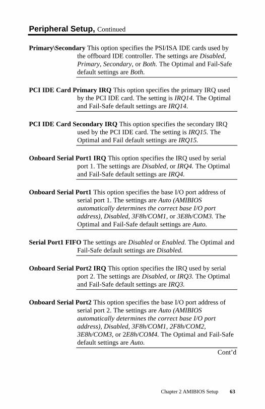
Offboard PCI\ISA IDE Card This option specifies whether an offboardPSI/ISA IDE card is used in the computer. You must alsospecify the PCI\ISA expansion slot on the motherboardwhere the offboard PCI\ISA controller card is installed. Ifan offboard PCI\ISA controller is used, the motherboardonboard IDE controller is automatically disabled. Thesettings are Absent, ISA, PCI Slot1, PCI Slot2, PCI Slot3,PCI Slot4, PCI Slot5, or PCI Slot6. The Optimal and Fail-Safe default settings are Absent.
Cont’d
Chapter 2 AMIBIOS Setup 63
Peripheral Setup, Continued
Primary\Secondary This option specifies the PSI/ISA IDE cards used bythe offboard IDE controller. The settings are Disabled,Primary, Secondary, or Both. The Optimal and Fail-Safedefault settings are Both.
PCI IDE Card Primary IRQ This option specifies the primary IRQ usedby the PCI IDE card. The setting is IRQ14. The Optimaland Fail-Safe default settings are IRQ14.
PCI IDE Card Secondary IRQ This option specifies the secondary IRQused by the PCI IDE card. The setting is IRQ15. TheOptimal and Fail default settings are IRQ15.
Onboard Serial Port1 IRQ This option specifies the IRQ used by serialport 1. The settings are Disabled, or IRQ4. The Optimaland Fail-Safe default settings are IRQ4.
Onboard Serial Port1 This option specifies the base I/O port address ofserial port 1. The settings are Auto (AMIBIOSautomatically determines the correct base I/O portaddress), Disabled, 3F8h/COM1, or 3E8h/COM3. TheOptimal and Fail-Safe default settings are Auto.
Serial Port1 FIFO The settings are Disabled or Enabled. The Optimal andFail-Safe default settings are Disabled.
Onboard Serial Port2 IRQ This option specifies the IRQ used by serialport 2. The settings are Disabled, or IRQ3. The Optimaland Fail-Safe default settings are IRQ3.
Onboard Serial Port2 This option specifies the base I/O port address ofserial port 2. The settings are Auto (AMIBIOSautomatically determines the correct base I/O portaddress), Disabled, 3F8h/COM1, 2F8h/COM2,3E8h/COM3, or 2E8h/COM4. The Optimal and Fail-Safedefault settings are Auto.
Cont’d

MegaRUM II PCI Motherboard User’s Guide64
Peripheral Setup, Continued
Serial Port2 Mode This option specifies the operating mode for serial port2.This option appears only if the Onboard Serial Port2option is not set to Auto or Disabled. The settings areIrDA, ASK IR, or Normal. The Optimal and Fail-Safedefault settings are Normal.
IR Duplex Mode This option specifies the infrared transmission method.This option appears only if the Onboard Serial Port2option is not set to Auto or Disabled. The settings are Fullor Half. There are no default settings.
Cont’dIrDA Protocol The settings are 1.6 us or 3/16. The Optimal and Fail-Safe
default settings are 1.6 us.
Onboard Parallel Port IRQ This option specifies the IRQ used by theparallel port. The settings are Disabled, IRQ7, or IRQ5.The Optimal and Fail-Safe default settings are IRQ7.
Parallel Port Mode This option specifies the parallel port mode. TheOptimal and Fail-Safe default settings are ECP. Thesettings are:
Setting DescriptionNormal The normal parallel port mode is used.EPP The parallel port can be used with devices that adhere to the
Enhanced Parallel Port (EPP) specification. EPP uses the existingparallel port signals to provide asymmetric bidirectional datatransfer driven by the host device.
ECP The parallel port can be used with devices that adhere to theExtended Capabilities Port (ECP) specification. ECP uses the DMAprotocol to achieve data transfer rates up to 2.5 Megabits persecond. ECP provides symmetric bidirectional communication.
Bi-Dir Data can be sent to and received from the parallel port.
Cont’d

Chapter 2 AMIBIOS Setup 65
Peripheral Setup, Continued
Parallel Port DMA Channel This option is available only if the setting forthe Parallel Port Mode option is ECP. This option setsthe DMA channel used by the parallel port. The settingsare Auto, (DMA Channel) 1, or 3.
EPP Version This option specifies the Enhanced Parallel Portspecification version number that is used in the system.This option appears only if the Parallel Port Mode optionis set to EPP. The settings are 1.7, 1.9, and N/A.
There are no Optimal and Fail-Safe default settingsbecause the default setting for the Parallel Port Modeoption is not EPP. If the Parallel Port Mode is set toNormal or ECP, then N/A displays.

MegaRUM II PCI Motherboard User’s Guide66
Section 7 Other Setup OptionsAuto-Detect Hard Disks
Choose this option to let AMIBIOS automatically detectthe hard disk drive parameters. The Standard CMOSSetup screen will appear after AMIBIOS has configuredthe drives. Press <Esc> and choose Save Settings and Exitto reconfigure the system configuration with the new harddisk drive parameters.
AMIBIOS Password Support
Two Levels of Password Protection AMIBIOS provides both a Supervisorand a User password. If you use both passwords, theSupervisor password must be set first.
The system can be configured so that all users must entera password every time the system boots or whenAMIBIOS Setup is executed, using either or both theSupervisor password or User password.
The Supervisor and User passwords activate two differentlevels of password security.
Set the Password Check option in Advanced Setup (seethe Advanced Setup section ) by choosing either Always(the password prompt appears every time the system ispowered on) or Setup (the password prompt appears onlywhen AMIBIOS Setup is executed). The password isencrypted and stored in NVRAM.
If you select password support, you are prompted for a 1 –6 character password. Type the password on the keyboard.The password does not appear on the screen when typed.Make sure you write it down. If you forget it, you mustdrain NVRAM and reconfigure.
Remember the Password Keep a record of the new password when thepassword is changed. If you forget the password, you musterase the system configuration information in NVRAM(Non-Volatile Random Access Memory). See page 75 forinformation about erasing system configurationinformation.

Chapter 2 AMIBIOS Setup 67
Change User Password
Select Change User Password from the AMIBIOS Setupmain menu.
Enter new User password:
appears. Type the password and press <Enter>. Thescreen does not display the characters entered. Retype thepassword as prompted and press <Enter>. If the passwordconfirmation is incorrect, an error message appears. Thepassword is stored in NVRAM after AMIBIOS completes.The next time the system boots, a password promptappears if the Password Check option is set to Always.
Change Supervisor Password
Select Change Supervisor Password from the AMIBIOSSetup main menu.
Enter new supervisor password:
appears. Type the password and press <Enter>. Thescreen does not display the characters entered. Retype thepassword as prompted and press <Enter>. If the passwordconfirmation is incorrect, an error message appears. Thepassword is stored in NVRAM after AMIBIOS completes.The next time the system boots, a password promptappears if the Password Check option is set to Always.
Change Language Settings
This option is not implemented in this AMIBIOS.

MegaRUM II PCI Motherboard User’s Guide68
Auto Configuration with Optimal Settings
AMIBIOS will automatically set all AMIBIOS Setupoptions to a complete set of default settings when youchoose this option. The following appears:
Load high performance settings (Y/N) ? N
The Optimal settings are designed for maximum systemperformance, but may not work best for all computerapplications. In particular, do not use the OptimalAMIBIOS Setup options if your computer is experiencingsystem configuration problems.
Auto Configuration with FailSafe Settings
AMIBIOS will automatically set all AMIBIOS Setupoptions to a complete set of default settings when youchoose this option. The following appears:
Load Failsafe settings (Y/N) ? N
The Fail-Safe settings are designed for maximum systemstability, but not maximum performance. Choose the Fail-Safe AMIBIOS Setup options if your computer isexperiencing system configuration problems.
Save Settings and Exit
When you have completed the system configurationchanges, choose this option to leave AMIBIOS Setup andto reboot the computer so the new system configurationparameters can take effect.
Exit Without Saving
Choose this option to quit AMIBIOS Setup withoutmaking any permanent changes to the systemconfiguration.

Chapter 2 AMIBIOS Setup 69


Chapter 3 Programming the Flash ROM 71
3 Programming Flash ROMAll versions of the MegaRUM II PCI motherboard useFlash EPROM to store the system BIOS. The advantage ofFlash EPROM is the EPROM chip does not have to bereplaced to update the BIOS. The end user can actuallyreprogram the BIOS, using a ROM file supplied byAmerican Megatrends.
Programming the Flash EPROM
Step Action1 Turn power off. Make sure the computer has a working speaker.2 Insert the floppy disk with the S774P.ROM file in drive A:.3 Press and hold the <Ctrl> and <Home> keys down while turning the
power on. Continue to hold the <Ctrl> and <Home> keys down until theaccess light on the floppy drive comes on. It may take 10 seconds ormore before this light turns on.
Since MegaRUM II uses a 2 megabit BIOS, the flashing process maytake up to 3 minutes.
4 Release the <Ctrl> and <Home> keys. AMIBIOS issues a series of beepcodes that indicate that the system BIOS ROM file is being updated.
5 When the flash ROM has successfully been programmed, the computerwill reboot.
6 When the computer reboots, check the BIOS Release text at the bottomof the first boot screen to make sure that the correct BIOS has beenused.
7 The error message
NVRAM checksum bad, NVRAM cleared
will appear during the first boot after a successful BIOS ROM update.This message indicates that the NVRAM area in the system BIOS hasbeen cleared. AMIBIOS will reconstruct the NVRAM area before thecomputer boots completely, so you can safely ignore this message.
8 Load the optional default and save.
Cont’d

MegaRUM II PCI Motherboard User’s Guide72
Programming the Flash ROM, Continued
Bootblock Actions When you reprogram from system boot, the bootblockcode:
Step Action1 Reads S774P.ROM from the root directory of the floppy disk in drive
A:.2 Erases the Flash EPROM.3 Programs the Flash EPROM with the data read from the floppy disk in
drive A:.4 Generates a CPU reset, rebooting the computer.
The bootblock part of the Flash EPROM is notprogrammed. Should you inadvertently open the diskdrive door or turn power off to the computer whileprogramming the Flash EPROM, the bootblock will beunaffected. Simply turn power back on and begin theFlash ROM programming process again.
S774P.ROM S774P.ROM resides on a floppy disk and contains theupdated main BIOS code. American Megatrends willprovide this file when the AMIBIOS for the MegaRUM IIPCI ISA motherboard must be updated.
S774P.ROM must be present in the root directory of thefloppy disk before the onboard Flash EPROM can bereprogrammed. The file that has the main BIOS codemust be named S774P.ROM.
Cont’d

Chapter 3 Programming the Flash ROM 73
Programming the Flash ROM, Continued
Beep Codes The bootblock code produces a series of beeps duringFlash ROM programming to: signify completion of a step(as shown on the previous page), or to signal an error.
Error beeps are arranged in a coded sequence and havedifferent meanings depending on when they occur. Theerror beep codes and when they can occur are:
Number ofBeeps
Description
1 Insert diskette in floppy drive A:.2 The S774P.ROM file was not found in the root directory of the
diskette in floppy drive A:.3 Base memory error.4 Flash program successful.5 Floppy read error.6 Keyboard controller BAT command failed.7 No Flash EPROM detected.8 Floppy controller failure.9 Boot Block BIOS checksum error.10 Flash erase error.11 Flash Program error.12 S774P.ROM file size error.
Continuousbeep
Flash Programming successful. Turn power off. Then turn power onagain to restart.

MegaRUM II PCI Motherboard User’s Guide74
Bootblock Code Checkpoint Codes
Code DescriptionE0h Verify the Boot Block BIOS checksum. Disable the internal
cache, DMA, and interrupt controllers. Initialize the systemtimer. Start memory refresh.
E1h Initialize the chipset registers. Set the BIOS size to 128K. Makethe 512 KB base memory available.
E2h Test the base 64 KB of system memory. Send the BAT commandto the keyboard controller. Make sure that <Ctrl> <Home> waspressed. Verify the main system BIOS checksum.
E3h The main system BIOS is good. Transfer control to the mainsystem BIOS.
E4h Start the memory test.E5h The memory test is over. Initialize the interrupt vector table.E6h Initialize the DMA and interrupt controllers.E7h Determine the CPU internal clock frequency.E8h Initialize the I/O chipset, if any.E9h Program the CPU clock-dependent chip set parameters.EAh Enable the timer and the floppy diskette interrupt. Enable the
internal cache. Copy the boot block BIOS and pass control to theboot block BIOS in the 0000h segment.
EDh Initialize the floppy drive.EEh Look for a diskette in drive A:. Read the first sector of the
diskette.EFh Floppy read error.F0h Search for S774P.ROM in the root directory of the floppy diskette
in drive A:.F1h The S774P.ROM file is not in the root directory.F2h Read the FAT table. Analyze the FAT to find the clusters
occupied by the S774P.ROM.F3h Start reading the S774P.ROM file, cluster by cluster.F4h The S774P.ROM file is not the correct size.F5h Disable the internal cache. Raise the Vpp. Enable Flash write and
reset the Flash ROM.FBh Detect the flash type.FCh Start erasing flash blocks.FDh Program the Flash ROM in the E0000-EFFFFh region.FEh Start programming Flash at F0000-FFFFF region.FFh Flash programming is successful. The computer reboots.

Chapter 4 Deleting a Password 75
4 Deleting a PasswordIf you forget the passwords you set up through AMIBIOSSetup, the only way you can restart the computer is toerase the system configuration information where thepasswords are stored. System configuration data is storedin CMOS RAM, a type of memory that consumes verylittle power.
Erase Old Password You can drain CMOS RAM power via J35 on themotherboard. J35 is a 2-pin berg that is normally alwaysOPEN. Perform the following steps to erase the oldpassword.
Important
Make sure you are properly grounded beforeperforming the following procedure. You must be
certain that no electrostatic discharge (ESD) occurs.ESD can ruin your motherboard. Wear an antistaticwristband attached to a ground. See “Avoid Static
Electricity” on the following page.
Step Action1 Turn the computer power off and remove the computer cover.2 Place a shorting bridge on J35.3 Turn on computer power for about 10 seconds.4 Turn the computer off again.5 Remove the shorting bridge from J35.6 Turn on computer power again.
Since you drained power from CMOS RAM, all systemconfiguration information has been erased. You must now re-enterthe system configuration information by running AMIBIOS Setup.

MegaRUM II PCI Motherboard User’s Guide76
Avoid Static Electricity
Static electricity can damage the motherboard and othercomputer components. Keep the motherboard in the anti-static bag until it is to be installed. Wear an anti-staticwrist grounding strap before handling the motherboard.Make sure you stand on an anti-static mat when handlingthe motherboard.
Avoid contact with any component or connector on anyadapter card, printed circuit board, or memory module.Handle these components by the mounting bracket.

Chapter 5 AMI ClientCare Installation Procedure 77
5 AMI_ClientCare InstallationProcedure
This procedure is valid when installing AMI_ClientCarein a computer with an AMI Series 774 MegaRUM IImotherboard.
Installation Requirements
• A computer with a Series 774 MegaRUM IImotherboard and a system BIOS that has the DMI-enabled BIOS file S774P.ROM, dated 11/05/98.
• The AMI_ClientCare installation CD
Procedure
Step 1 Flash the new S774P.ROM file on to the MegaRUM IIBIOS on the Series 774 MegaRUM II motherboard. SeeChapter 3, Flashing ROM BIOS, for information aboutflashing the BIOS. The new BIOS must be installed beforesystem information can be displayed correctly.
Step 2 Boot Windows NT on this computer after the new BIOShas been successfully installed.
Step 3 Place the AMI_ClientCare CD in the CD-ROM drive.Run the SETUP program on the AMI_ClientCare CD.Follow the instructions on the screen. See the AmericanMegatrends AMI_ClientCare User’s Guide (part numberMAN-CLIENT) for information about usingAMI_ClientCare.

MegaRUM II PCI Motherboard User’s Guide78

Appendix A Specifications 79
A SpecificationsEngineering Specifications
Temperature Ranges The following values are ambient temperaturesinside the computer case. The board temperatures reflectthe dual Pentium II II CPU Heat dissipation requirementsbecause they will be the hottest motherboard components.Temperature specifications vary with the CPU frequency.
Frequency HeatSink
Airflowover CPU
Airflowover other
components
TemperatureRange
All frequencies YES 200 feetper minute
Not critical 0 ° through 50 °C. ambient
You must make sure that there is adequate air flow overthe CPU inside the case.
Humidity The recommended humidity range for operation of themotherboard is 20% to 80% non-condensing.

MegaRUM II PCI Motherboard User’s Guide80

Index 81
Index
11st Boot Device, 47
22nd Boot Device, 47
33rd Boot Device, 48
44th Boot Device, 48
AACPI Aware O/S, 52Active termination, 35Add-On ROM Messages, 46Advanced Chipset Setup, 50Advanced Setup, 46AGP Low Priority Timer (AGP
Clks), 51AGP Multi-Trans Timer (AGP
Clocks), 51AGP Slot IRQ Priority, 57Allocate IRQ to PCI VGA, 56AMI ClientCare Installation
Procedure, 75Installation Requirements, 75
AMIBIOS Password Support, 65AMIBIOS Setup, 39AMIBIOS Setup Menu, 40AMIFlash
Beep Codes, 71ARMD, 43Auto Configuration with FailSafe
Settings, 67Auto Configuration with Optimal
Settings, 67
Auto-Detect Hard Disks, 65
BBIOS
Password Support, 65BIOS Errors, 38BIOS P.O.S.T Messages, 46Block Mode, 44Boot Sector Virus Protection, 42Boot To OS/2, 47Boot to SCO UNIX, 56Boot Up Num Lock, 46Bootblock
Checkpoint Codes, 72BX Master Latency Timer (Clks), 50
CCables
Attaching, 15Connecting, 16
CD-ROM driveConfiguring, 43
Change Language Settings, 66Change Supervisor Password, 66Change User Password, 66Chassis Door Open, 19CMOS Drain, 18COM1, 23COM2, 23Configure CPU, 5Configuring System, 38Conflicts, 23Connectors, 15
DIMM, 13Floppy disk, 25IDE Hard Disk Drive, 28Keyboard, 19Reset Switch, 20Serial ports, 23Speaker, 20
CPUInstall, 7

MegaRUM II PCI Motherboard User’s Guide82
CPU Fan, 6
DDate/Time, 41Device 0 (Primary Master IDE), 55Device 1 (Primary Slave IDE), 55Device 2 (Secondary Master IDE),
55Device 3 (Secondary Slave IDE), 55Device 5 (Floppy Disk), 55Device 6 (Serial Port 1), 55Device 7 (Serial Port 2), 55Device 8 (Parallel Port), 55DIMMs
Installing, 13Display Activity, 54DMA Channel 0, 59DMA Channel 1, 59DMA Channel 3, 59DMA Channel 5, 59DMA Channel 6, 59DMA Channel 7, 59
EEnhanced Parallel Port, 24EPP Version, 64Exit Without Saving, 67Extended Capabilities Port, 24
FFigures
Floppy drive cable, 25Floppy drive connector, 25
Flash EPROMProgramming, 69
Floppy Disk ConnectorPinout, 25
Floppy Drive A: and B, 42Floppy Drive connector
Pinout, 26
GGraphics Aperture Size, 51Green PC Monitor Power State, 52
HHard Disk Drive Capacity, 44Hard Disk Drive Parameters, 44Hard Disk Drive Type D:, 43Hard Disk Power Down Mode, 53Hard Disk Timeout (Minute), 53Heat sink, 10High Density Connectors, 32High-Density 68-Pin SCSI Connector
Pinout, 33
IIDE Bus Mastering, 61IDE drive
Configuring, 43IDE Hard Disk Connector, 28Install Memory, 12Install the Heat Sink, 10, 11Installing the Motherboard, 14Iomega Zip drive, 43IR Duplex Mode, 63IrDA Protocol, 63IRQ10, 59IRQ11, 59IRQ12, 59IRQ14, 59IRQ15, 59IRQ3, 59IRQ4, 59IRQ5, 59IRQ7, 59IRQ9, 59
JJ1 PS/2 Mouse Connector, 19J12 Keyboard Connector, 19J15 Keyboard Lock connector, 21J15 Wide SCSI channel 1 connector,
32J17 Wide SCSI channel 2 connector,
32J18 External SMI, 19J3 USB Connectors, 22J33 Erase Password, 73J47 SCSI Termination, 31J5 Parallel Port connector, 24

Index 83
J6 Serial Port 1 (COM1), 23J7 Serial Port 2 (COM2), 23J9 Pinout, 31JP 11 Drain CMOS RAM power, 18JP 16 Power Button, 22JP1 CPU Fan, 6JP13 Chassis Door Open, 19JP14 BIOS Size Select, 22JP15 BIOS Chip Voltage Select, 20JP17 Reset Switch Connector, 20JP18 Chassis Fan, 6JP19 Chassis Fan, 6JP2 CPU Fan, 6JP20 Speaker Connector, 20JP3 Infrared Connector, 18JP4 Pinout, 30JP4 Secondary IDE Controller, 29JP5 IDE Connector
Primary, 28JP5 Pinout, 29JP9 Floppy Connector, 25
KKeyboard, 47Keyboard connector, 19
LLBA Mode, 44LS-120 drive, 43
MMagneto-Optical drive, 43MegaRAC PCI adapter, 31Memory
Reporting, 12Monitor, 46Mouse Cable, 19Mouse Support, 46Multi-Trans Timer (Clks), 50
NNumber of Cylinders, 44Number of Heads, 44Number of Sectorss, 44
NVRAM (Non-Volatile RandomAccess Memory), 65
OOffboard PCI\ISA IDE Card, 61Onboard Adapters, 23Onboard Floppy Controller, 61Onboard I/O, 2Onboard Parallel Port IRQ, 63Onboard Primary/Secondary IDE, 61Onboard Serial Port1, 62Onboard Serial Port2, 62Onboard Serial Port2 IRQ, 62Optional USB Cable, 22Outboard SCSI-1, 50Outboard SCSI-2, 50Overview, 1
PP1 Power connector, 17P3 Power connector, 17Parallel Port, 24Parallel Port DMA Channel, 64Parallel Port Mode, 63Password
Deleting, 73Password Check, 46Password Support
Levels of, 65PCI Bus Speed, 1PCI IDE Card Primary IRQ, 62PCI IDE Card Secondary IRQ, 62PCI SCSI-1 IRQ Priority, 58PCI SCSI-1 Latency, 58PCI SCSI-2 IRQ Priority, 58PCI SCSI-2 Latency, 58PCI SCSI-5 IRQ Priority, 58PCI SCSI-5 Latency, 58PCI SCSI-6 IRQ Priority, 58PCI SCSI-6 Latency, 58PCI Slot1 IRQ Priority, 58PCI Slot-1 Latency, 57PCI Slot-2 Latency, 57PCI Slot-3 Latency, 57PCI Slot-4 Latency, 57PCI VGA Palette Snoop, 56PCI/PnP Setup, 56

MegaRUM II PCI Motherboard User’s Guide84
Pentium II, 1Peripheral Setup, 61Pinout
Parallel Port, 24Primary IDE connector, 29Serial ports, 23
PinoutsKeyboard lock, 21Reset Switch, 20Serial ports, 23
PIO Mode, 44Plug and Play-Aware OS, 56Power Button Function, 52Power Management Setup, 52Power Management/APM, 52Power Saving Type, 53Power Supply, 17
Connecting, 17Pri Master, Pri Slave, Sec Master,
Sec Slave, 43Primary Display, 46Primary Prefetch, 61Primary\Secondary, 62PS/2 mouse support, 46PS/2Mouse Support, 46
QQuick Boot, 47
RReporting Memory, 12Reserved ISA Card Memory
Address, 60Reserved ISA Card Memory Size, 60Reset Switch Connector, 20Resource conflicts, 23Retention Mechanism Kit, 8
SS.M.A.R.T. for Hard Disks, 47S774P.ROM, 70S774P.ROM file, 69Save Settings and Exit, 67SCSI Cable Considerations, 34SCSI Cables, 35SCSI Connectors, 32
SCSI DriversInstalling, 37
SCSI Signal Path, 34SCSI Termination, 35SCSI Termination Possibilities, 36SDRAM DIMM Sockets, 12SDRAM Speed (ns), 12Secondary IDE Controller, 29Secondary Prefetch, 61Serial port
Pinout, 23Serial Port1 FIFO, 62Serial Port2 Mode, 63Server Management Software, 2Shadow C800,16K, 49Shadow CC00,16K, 49Shadow D000,16K, 49Shadow D400,16K, 49Shadow D800,16K, 49Shadow DC00,16K, 49Slow Clock Ratio, 54Speaker Cable Connector, 20Standard CMOS Setup Screen, 41Standard Setup, 41Standby Timeout, 54Standby/Suspend Timer Unit, 53Static Electricity, 4, 74Stub length, 35Suspend Timeout, 54System Bus Frequency, 5System Keyboard, 47System memory, 12SystemGuru
Installing, 37
TTables
Floppy pinout, 26Hard Disk Drive Types, 45I/O conflicts, 23Serial port pinout, 23Twist in floppy cable, 26
Termination card, 7Testing System, 38Try Other Boot Devices, 48

Index 85
UUnpack the Motherboard, 4USB Connectors, 22USB Device IRQ Priority, 57USB Function, 50
VVideo Power Down Mode, 53Video Shadow C000,16K, 48Video Shadow C400,16K, 48Voltage Regulator Module (VRM), 6
WWrite Precompensation, 44

MegaRUM II PCI Motherboard User’s Guide86