Embed Size (px)
Citation preview

Title: Medupi FGD Retrofit Technology Selection Study Report
Unique Identifier: 474-10175
Alternative Reference Number: 178771.41.0050
Area of Applicability: Engineering
Documentation Type: Report
Revision: 1
Total Pages: 23
Next Review Date: N/A
Disclosure Classification: CONTROLLED DISCLOSURE
Compiled by Functional Responsibility Authorised by
………………………………….. ………………………………….. …………………………………..
David Harris
Project Manager
Black & Veatch
Anton Hart
Boiler Auxiliaries Manager
Eskom
Danie Odendaal
General Manager: Gx Plant Engineering
Eskom
Date: …………………………… Date: …………………………… Date: ……………………………
Report Technology

CONTROLLED DISCLOSURE
When downloaded from the EDS, this document is uncontrolled and the responsibility rests with the user to ensure it is in line with the authorised version on the system.
Medupi FGD Retrofit Technology Selection Study
Report
Unique Identifier: 474-10175
Revision: 1
Page: 2 of 23
CONTENTS
Page
1. INTRODUCTION ..................................................................................................................................................... 4
1.1 STUDY OBJECTIVES ....................................................................................................................................... 4
2. SUPPORTING CLAUSES ...................................................................................................................................... 4
2.1 SCOPE .............................................................................................................................................................. 4 2.1.1 Purpose ..................................................................................................................................................... 5 2.1.2 Applicability ............................................................................................................................................... 5
2.2 NORMATIVE/INFORMATIVE REFERENCES ................................................................................................. 5 2.2.1 Normative .................................................................................................................................................. 5 2.2.2 Informative ................................................................................................................................................ 5
2.3 DEFINITIONS ................................................................................................................................................... 5 2.3.1 Classification ............................................................................................................................................. 5
2.4 ABBREVIATIONS ............................................................................................................................................. 6 2.5 ROLES AND RESPONSIBILITIES ................................................................................................................... 6 2.6 PROCESS FOR MONITORING ....................................................................................................................... 6 2.7 RELATED SUPPORTING DOCUMENTS ........................................................................................................ 7
3. TECHNOLOGY EVALUATION .............................................................................................................................. 7
3.1 STUDY DESIGN BASIS.................................................................................................................................... 7 3.1.1 Existing Facilities ....................................................................................................................................... 7 3.1.2 Design Criteria .......................................................................................................................................... 7
3.2 TECHNOLOGY ALTERNATIVES ..................................................................................................................... 8 3.2.1 Alternative Cases to be Considered ......................................................................................................... 8
3.2.1.1 WFGD ............................................................................................................................................... 8 3.2.1.2 WFGD with Inlet Gas Cooler............................................................................................................. 8 3.2.1.3 Dry and Semi-Dry FGD ..................................................................................................................... 9
3.2.2 Retrofit Technology Descriptions ............................................................................................................ 10 3.2.2.1 WFGD – Limestone Reagent .......................................................................................................... 10 3.2.2.2 WFGD – Limestone Reagent with Inlet Flue Gas Cooling ............................................................. 10 3.2.2.3 Dry CFB Technology ....................................................................................................................... 11
3.2.3 Consideration of Balance of Plant Systems Changes ............................................................................ 11 3.2.3.1 WFGD ............................................................................................................................................. 11 3.2.3.2 WFGD with Cooler .......................................................................................................................... 11 3.2.3.3 Semi-Dry CFB ................................................................................................................................. 12
3.3 COST COMPARISON ..................................................................................................................................... 12 3.3.1 Capital Cost Estimates ............................................................................................................................ 13 3.3.2 Contingency ............................................................................................................................................ 14 3.3.3 Estimate Exclusions ................................................................................................................................ 14
3.4 OPERATIONS AND MAINTENANCE COSTS ............................................................................................... 14 3.4.1 Reagent Costs ........................................................................................................................................ 15 3.4.2 Auxiliary Power Costs ............................................................................................................................. 16 3.4.3 Water Costs ............................................................................................................................................ 16 3.4.4 Steam Costs ............................................................................................................................................ 16 3.4.5 Water Disposal Costs .............................................................................................................................. 16 3.4.6 Byproduct Disposal Costs ....................................................................................................................... 16 3.4.7 Operating Labour Costs .......................................................................................................................... 17 3.4.8 Maintenance Material and Labour Costs ................................................................................................ 17
3.5 LIFE-CYCLE COST ANALYSIS ...................................................................................................................... 17 3.5.1 Comparative Total Annual Costs ............................................................................................................ 17 3.5.2 Life-Cycle Cost Analysis ......................................................................................................................... 18
3.5.2.1 Comparative Cumulative Present Worth ........................................................................................ 18 3.6 RECOMMENDATION ..................................................................................................................................... 19
4. AUTHORISATION ................................................................................................................................................ 20

CONTROLLED DISCLOSURE
When downloaded from the EDS, this document is uncontrolled and the responsibility rests with the user to ensure it is in line with the authorised version on the system.
Medupi FGD Retrofit Technology Selection Study
Report
Unique Identifier: 474-10175
Revision: 1
Page: 3 of 23
5. REVISIONS ........................................................................................................................................................... 21
6. DEVELOPMENT TEAM ........................................................................................................................................ 21
7. ACKNOWLEDGEMENTS ..................................................................................................................................... 22
APPENDIX A LIST OF ATTACHMENTS .................................................................................................................. 23
FIGURES
Figure 1: Cumulative Present Worth Analysis........................................................................................................... 19
TABLES
Table 1: Key Parameters ............................................................................................................................................. 7 Table 2: Capital Cost Estimate Summary (1,000 ZAR) ............................................................................................ 13 Table 3: Consumption Rates ...................................................................................................................................... 15 Table 4: Levelised Annual Costs (1,000 ZAR) .......................................................................................................... 18

CONTROLLED DISCLOSURE
When downloaded from the EDS, this document is uncontrolled and the responsibility rests with the user to ensure it is in line with the authorised version on the system.
Medupi FGD Retrofit Technology Selection Study
Report
Unique Identifier: 474-10175
Revision: 1
Page: 4 of 23
1. INTRODUCTION
The Medupi Power Station will consist of six 800 megawatt (MW) coal fired steam electric generating units located in Limpopo Province, approximately 15 kilometres (km) west of the town of Lephalale, South Africa. The units are planned to enter commercial operation sequentially beginning in December 2013. The Medupi Power Station Flue Gas Desulphurisation (FGD) Retrofit Project will result in the addition of FGD systems to each of the operating units. Each FGD system will be operational within 6 years from the date of commercial operation of the respective generating unit.
In 2005, Eskom commissioned a technology review of FGD technologies [9] that would be available for the new generating fleet additions planned for 2012, in accordance with the National Integrated Resource Plant form 2003/2004 Reference Case, which would be required to meet new emissions regulations for sulphur dioxide (SO2). As a result of this analysis, the Medupi Power Station planning included consideration and provisions for the eventual addition of a wet limestone flue gas desulphurisation scrubber (WFGD).
A conceptual design for the installation of a WFGD was developed by the collaborative team of Eskom, Steinmüller Engineering, and Black & Veatch in May 2012 [11] and included conceptual level project scope definition, and estimated capital and operations and maintenance costs. Conceptual design for the FGD process and associated facilities was performed by the team for the complete scope of work necessary to fully integrate the FGD into the operating plant. This conceptual design serves as a reference for comparison of the alternative FGD technologies.
The purpose of this study is to identify the most economically viable technology for reducing SO2 emissions to 400 milligrams per normal cubic metre (mg/Nm3) at the Medupi Power Station. The study will evaluate the capital cost requirement and annual operating costs of semi-dry FGD (DFGD) and WFGD, with and without gas cooling, as applied to units at the Medupi Power Station. This analysis will be based on the FGD Technology Selection Study Design Basis [3] derived from the Project Design Manual for the Medupi FGD Retrofit Project [10].
1.1 STUDY OBJECTIVES
The study assesses the capital and operating and maintenance costs associated with a single fuel, reagent quality, and generating load case for the three FGD technologies.
The FGD Technology Selection Study Design Basis [3] serves as the basis for all calculations, cost estimates, and economic evaluations (capital and operating), including but not limited to: fuel/reagent consumption, auxiliary power requirements, and waste disposal including unit capacity factors, flue gas flow rates, air emission rates, SO2 reduction requirements, flue gas temperature, ash and/or byproduct production rates, reagent utilisation, and other operating parameters that affect the design of the emissions control equipment.
2. SUPPORTING CLAUSES
2.1 SCOPE
This document contains the conceptual design and capital and operating cost estimates for the two technologies and the one modification to a proposed technology considered most applicable to the SO2 control required to retrofit the operating units at the Medupi Power Station. The information presented will discuss the equipment sizing, equipment configuration, cost estimates, operating costs, and life-cycle cost estimates for all three technologies.

CONTROLLED DISCLOSURE
When downloaded from the EDS, this document is uncontrolled and the responsibility rests with the user to ensure it is in line with the authorised version on the system.
Medupi FGD Retrofit Technology Selection Study
Report
Unique Identifier: 474-10175
Revision: 1
Page: 5 of 23
2.1.1 Purpose
The purpose of this document is to identify the most economically viable technology for reducing SO2 emissions to 400 mg/Nm3 at the Medupi Power Station.
2.1.2 Applicability
This document shall apply throughout Eskom Holdings Limited Divisions with specific reference to the Medupi Power Station.
2.2 NORMATIVE/INFORMATIVE REFERENCES
Parties using this document shall apply the most recent edition of the documents listed in the following paragraphs.
2.2.1 Normative
[1] Design Base Standard – Doc no: 474-190.
[2] Design Review Procedure – Doc no: 240-5311 3685.
[3] Technology Selection Study Design Basis (Black & Veatch file no.: 178771.41.0051) - Doc no: [LATER].
2.2.2 Informative
[4] Medupi User Requirements (URS) Rev. 4 – Doc no: NC/001.
[5] Medupi Project Design Manual (PDM) – Doc no: 200-32065.
[6] Eskom Air Quality Strategy – Doc no: ESG32-1143.
[7] National Environmental Management Act 2004 (Act 39 2004).
[8] Listed Activities and Associated Minimum Emission Standards Identified in Terms of Section 21 of the National Environmental Management: Air Quality Act, 2004 (Act 39 2004).
[9] FGD Technology Review – Doc no: RES/RR/04/24115.
[10] Medupi FGD Retrofit Project Design Manual (PDM) – Doc no: 200-61989
[11] Medupi FGD Retrofit Conceptual Design Report (CDR) – Doc no: 200-61771
2.3 DEFINITIONS
2.3.1 Classification
Controlled disclosure: controlled disclosure to external parties (either enforced by law, or discretionary).

CONTROLLED DISCLOSURE
When downloaded from the EDS, this document is uncontrolled and the responsibility rests with the user to ensure it is in line with the authorised version on the system.
Medupi FGD Retrofit Technology Selection Study
Report
Unique Identifier: 474-10175
Revision: 1
Page: 6 of 23
2.4 ABBREVIATIONS
Abbreviations Description
BOP Balance-of-Plant
°C Centigrade
CaCO3 Calcium Carbonate (limestone)
CaO Calcium Oxide (lime or quick lime)
Ca(OH)2 Calcium Hydroxide (hydrated lime)
CDR Medupi FGD Retrofit Conceptual Design Report [11]
CFB Circulating Fluid Bed (FGD)
DFGD Dry or Semi-Dry Flue Gas Desulphurisation
FFP Fabric Filter Plant
FGD Flue Gas Desulphurisation
ID Induced Draught
kg/h Kilograms/hour
km Kilometres
kPa Kilopascal
µm Micron (micrometre)
m3 Cubic Metres
mbar millibar
mg/Nm3 Milligram per Normal Cubic Metre (0º C and 1 atmosphere, dry basis at 6% O2)
MW Megawatt
O2 Oxygen
PDM Project Design Manual
SDA Spray Dryer Absorber (semi-dry flue gas desulphurisation)
SO2 Oxides of Sulphur
URS User Requirements Specification
WFGD Wet (limestone) Flue Gas Desulphurisation
ZLD Zero Liquid Discharge
2.5 ROLES AND RESPONSIBILITIES
Wolfgang Bloss Steinmüller Project Manager Input
David Harris Black & Veatch Project Manager Compile
Justice Bore Eskom Project Engineering Manager
Review
2.6 PROCESS FOR MONITORING
Progress of the conceptual and basic design development will be monitored using the project schedule.

CONTROLLED DISCLOSURE
When downloaded from the EDS, this document is uncontrolled and the responsibility rests with the user to ensure it is in line with the authorised version on the system.
Medupi FGD Retrofit Technology Selection Study
Report
Unique Identifier: 474-10175
Revision: 1
Page: 7 of 23
2.7 RELATED SUPPORTING DOCUMENTS
Not Applicable.
3. TECHNOLOGY EVALUATION
3.1 STUDY DESIGN BASIS
The study design basis was established at the outset of the project to define the performance and functional requirements to which each of the FGD technologies are to be evaluated.
3.1.1 Existing Facilities
The Medupi Plant is currently under construction. The design and construction of each of these units includes provisions incorporated into the space and equipment design to accommodate the installation of WFGD systems. Each of the six generating units is independently operated; common facilities are provided for electrical power, water, coal supply, and coal combustion waste disposal.
The design of each of the units currently includes the installation of fabric filters and induced draught (ID) fans. The fabric filters remove the majority of the fly ash from the coal combustion process, and the ID fans provide the necessary draft to overcome the system resistance. The design of the ID fans includes an additional margin to overcome the additional 25 millibar (mbar) (2.5 kilopascals [kPa]) system resistance due to the future installation of WFGD equipment.
The ID fans will originally discharge directly to the chimney flue associated with each unit. The FGD system retrofit will include additional dampers and ductwork to divert flue gas to the FGD absorbers and return it to the chimney and to provide a bypass of the FGD systems as may be required by system operation. The chimney flues have corrosion-resistant liners to handle the saturated flue gas resulting from future operation of an FGD plant.
Each WFGD or DFGD system will treat the flue gas from one of the six boilers. A cluster of three FGD systems will be located near each of the plant’s two chimneys. Systems for process water, reagent preparation, FGD byproduct handling and storage/disposal, and treatment of the wastewater stream will be common to all FGD absorbers in the plant, except in the case of the DFGD system where dedicated lime preparation equipment would be included for each FGD system and a wastewater treatment system would not be required since a waste stream is not generated.
3.1.2 Design Criteria
The FGD Technology Selection Study Design Basis [3] is consistent with the Medupi FGD Retrofit Project PDM [10]. The key parameters are summarised in Table 1.
Table 1: Key Parameters
Description Unit Wet FGD Wet FGD + Cooler CFB
Reagent - Limestone CaCO3 Limestone CaCO3 Hydrated lime Ca(OH)2
Reagent purity % 96.0 96.0 94.7
Temperature raw gas °C 145 145 / 100* 137
Flue gas flow (std., wet) m³/h 2,495,520 2,495,520 2,495,520
SO2 removal efficiency - 94.06 94.06 94.06

CONTROLLED DISCLOSURE
When downloaded from the EDS, this document is uncontrolled and the responsibility rests with the user to ensure it is in line with the authorised version on the system.
Medupi FGD Retrofit Technology Selection Study
Report
Unique Identifier: 474-10175
Revision: 1
Page: 8 of 23
Outlet SO2 concentration mg/Nm3 400 @ 6% O2 400 @ 6% O2 400 @ 6% O2
Outage duration Weeks 6 6 6
*Lower temperature not possible, due to Mist Eliminator flushing requirements.
3.2 TECHNOLOGY ALTERNATIVES
Previous studies have identified other commercially available SO2 control technologies that could be employed to meet the requirements of controlling the output of Medupi generating units 1 to 6 to less than 400 mg/Nm3, as required by the emissions limitations for the station.
Two technologies and one modification to a proposed technology are discussed in this study, as they were identified in previous analysis to be the most applicable technologies to meet the additional requirements of water use, SO2 emission rate, and byproduct disposal for the site. The technologies of WFGD and a DFGD of the circulating fluid bed (CFB) absorber type will be evaluated in this report. This report will include discussions of the technologies, the applicability and process flow diagrams for the Medupi application, and a budgetary cost and operations and maintenance cost analysis.
The WFGD is being studied in two similar configurations: one with the FGD inlet coming directly from the system ID fans and one where the inlet flue gas is cooled by a water-cooled closed loop heat exchanger to minimise the water evaporation in the WFGD process.
3.2.1 Alternative Cases to be Considered
3.2.1.1 WFGD
WFGD technology has a long history of application to fossil fired generating facilities in units of all sizes. WFGD remains the predominant process utilised today, particularly in retrofit applications, due to its high SO2 removal capability, high inlet sulphur capability, and retrofit suitability. Wet limestone-based FGD processes are most frequently applied to pulverised coal fired boilers that combust medium-to-high sulphur coals. Typically, the WFGD processes on a coal facility are characterised by high removal efficiency (greater than 98 percent) and high reagent utilisation (95 to 97 percent) when combined with a high sulphur fuel. The ability to realise high removal efficiencies on higher sulphur fuels is a major difference between wet scrubbers and semi-dry/dry FGD processes.
In a WFGD system, the absorber module is located downstream of the ID fans (or booster fans, if required), placing the retrofit WFGD downstream of any existing particulate control device. This location typically eliminates the need for the addition of another particulate control device and the WFGD usually provides some additional particulate control itself. Flue gas exiting the fans enters the module and is contacted with slurry containing reagent and byproduct solids. The SO2 is absorbed into the slurry and reacts with the calcium to form calcium sulphite hemi-hydrate (CaSO3• ½H2O) and calcium sulphate dihydrate (CaSO4•2H2O, also called “gypsum”). On most new WFGD systems, oxidation air is blown into the absorber tank to push the reactions to creating gypsum and very little CaSO3• ½H2O. This helps in the process chemistry to virtually eliminate scaling and plugging of the absorber and can allow for the sale of byproduct for wallboard production or other industry purposes, if a suitable market exists in the nearby region. To create a marketable byproduct, most times a wastewater stream is necessary to purge impurities such as chlorides from the system. Such a wastewater stream may be avoided if a wetter byproduct is sent to waste.
3.2.1.2 WFGD with Inlet Gas Cooler
The WFGD with inlet gas cooler technology is a modification to the WFGD technology that uses a heat exchanger at the inlet of the FGD to reduce the temperature of the flue gas flowing to the absorber, thereby reducing the amount of water evaporated as the flue gas cools to the saturation temperature.

CONTROLLED DISCLOSURE
When downloaded from the EDS, this document is uncontrolled and the responsibility rests with the user to ensure it is in line with the authorised version on the system.
Medupi FGD Retrofit Technology Selection Study
Report
Unique Identifier: 474-10175
Revision: 1
Page: 9 of 23
Two methods of cooling can be utilised. The first method uses a regenerative gas-to-gas heater to remove heat from the incoming flue gas, then uses this heat to reheat the clean flue gas, increase flue gas buoyancy, and reduce water condensation in the chimney flue. A regenerative heater exchanger would have a total pressure drop of 16 mbar in a regenerative mode. This pressure drop across the WFGD system would exceed the maximum pressure drop allocated to the WFGD in the design of the existing plant ID fans.
The second method to cool the gas uses a single pass water-cooled heat exchanger. A single pass cooler for the flue gas will limit the pressure drop to within the capability of the existing plant ID fan. The heat recovered from the flue gas can be diverted to another low temperature heat demand elsewhere in the plant.
The inlet gas cooler will reduce the flue gas inlet temperature to the absorber from 145° C to 100° C and the outlet temperature of the absorber from approximately 52° C to 49° C.
3.2.1.3 Dry and Semi-Dry FGD
DFGD processes, including the spray dryer absorber (SDA) process and CFB process have been extensively used for SO2 control. The DFGD technology uses less water than typical WFGD systems in that the flue gas is not saturated with water and uses hydrated lime instead of limestone as a reagent for SO2 capture. The system also mixes the water, lime, and fly ash-laden flue gas in a reactor, which then passes to a fabric filter to remove all the byproducts of desulphurisation and the fly ash from the flue gas stream. This technology is evaluated in this report as representative of all semi-dry FGD technologies (refer to Section 3.2.2.3).
Utilities have installed numerous dry and semi-dry FGD systems on boilers using low sulphur fuels. These installations generally have DFGD systems designed for a maximum fuel sulphur content of less than 2 percent. The CFB process uses calcium hydroxide [Ca(OH)2] produced from the lime (CaO or "quick lime") reagent as a dry powder to the flue gas in a reactor designed to provide good gas-reagent contact. SDA systems use Ca(OH)2 injected as a liquid slurry. The SO2 in the flue gas reacts with the calcium in the reagent to produce primarily a mix CaSO3•1/2H2O and CaSO4•2H2O.
An evaluation of the SDA, CFB, and other semi-dry modular technologies on experience, fuel flexibility, SO2 emissions control, site layout, operability, capital cost, and operating costs indicates that these systems are fairly comparable in most areas as considered in the 2005 FGD Technology Review [9]. Increased utilisation of these technologies and some process developments are now resulting in higher SO2 removal guarantees with a lower corresponding risk as to lime consumption.
SDA technology has an experience advantage over CFB and modular technologies. SDA systems have been designed for units in excess of 900 MW using multiple absorber vessels, with each vessel handling the flow equivalent to 450 MW. The range of experience for the CFB and modular systems indicates that these technologies have sufficient range of operational and design experience to be considered applicable; however as with the SDA, multiple CFB reactors would be required for each unit.
SO2 removal efficiency of the SDA technology has been enhanced by hydrated lime injection into the SDA inlet by at least one manufacturer to allow it to now quote 96 to 98 percent SO2 removal, which is similar to CFB technologies for low to medium sulphur coals.
The main difference between the SDA and CFB processes is the preparation of the lime into calcium hydroxide. Slakers produce a paste with approximately 10 to 13 percent lime mixed with water and are typically used with the SDA technology. This can limit the amount of lime (and, as such, SO2 removed) added to the process due to the transport water causing the flue gas to approach dew point.
Since one of the features of the CFB is the ability to control the amount of lime independent of water, CFB systems are supplied with lime hydrators that convert the pebble lime to calcium hydroxide. The hydrated lime is stored in a separate hydrated lime silo for application to the scrubbing absorber module,

CONTROLLED DISCLOSURE
When downloaded from the EDS, this document is uncontrolled and the responsibility rests with the user to ensure it is in line with the authorised version on the system.
Medupi FGD Retrofit Technology Selection Study
Report
Unique Identifier: 474-10175
Revision: 1
Page: 10 of 23
as required. This allows for a spare lime hydrators to be incorporated and the product to be stored to allow for maintenance and redundancy in the reagent preparation systems similar to the operation of the WFGD.
There are DFGD technologies where a group of small flash dry modules are clustered together for parallel operation. Modules are removed from service to facilitate partial load operation. This is in lieu of the recirculation duct used in the CFB to keep adequate gas velocities in the absorber, to keep the CFB absorber bed fluidised.
Another consideration for the DFGD technologies is the elimination of the potential to produce a saleable byproduct such as that produced from the WFGD systems. There is no known commercial use for the byproduct of the DFGD processes, which is captured as a mixture with the fly ash in the fabric filter downstream of the absorber. This requires the byproduct from the DFGD to be disposed of, typically in a landfill.
No wastewater is produced with the DFGD technology as all water is evaporated or contained as waters of hydration in the dry byproduct mixture. This eliminates the capital and operating costs of an additional wastewater treatment system when considering the application of this technology. Other water streams at the plant may require treatment for reuse, but they are not associated with the scrubbing process and are, therefore, not included in the cost analysis.
3.2.2 Retrofit Technology Descriptions
3.2.2.1 WFGD – Limestone Reagent
This technology was recommended in the Medupi FGD Retrofit CDR [11], which is the basis for this technology evaluation. There is no change from the CDR in the basic system design or layout of the mechanical, civil/structural, or electrical systems required for installation. The systems will include limestone handling, limestone preparation, makeup water, byproduct separation and disposal, liquid recycling, and chemical processing of the process bleed stream to produce a solids byproduct that requires landfill and water that will be reused in the plant.
The CDR WFGD system design includes an absorber system with five spray levels in the absorber tower that allows for a design emission rate of 400 mg/Nm3 at full load on the worst anticipated coal and accounts for attemperating air required during cases of high fabric filter plant (FFP) inlet temperatures to protect the equipment.
The CDR WFGD system design includes all balance-of-plant (BOP) equipment required for the successful integration of the new equipment into the existing plant.
The process flow diagram for the technology case study design basis is shown on drawing 006265-R-PFD-005.
3.2.2.2 WFGD – Limestone Reagent with Inlet Flue Gas Cooling
The WFGD with inlet gas cooler technology is a modification to the WFGD technology. This modification uses a heat exchanger at the inlet of the FGD to reduce the temperature of the flue gas flowing to the absorber and, thereby, reduces the amount of water evaporated as the flue gas cools to the saturation temperature. This modification to the process design is reflected in process flow diagram 006265-R-PFD-021 (attached).
For the six units at Medupi, the total reduction in the process water to the FGD is approximately 29 percent of the water required by the WFGD system without a cooler. The reduced water consumption provides significant savings in this critical resource and is the reason for inclusion of this modification in this phase of the technology assessment.

CONTROLLED DISCLOSURE
When downloaded from the EDS, this document is uncontrolled and the responsibility rests with the user to ensure it is in line with the authorised version on the system.
Medupi FGD Retrofit Technology Selection Study
Report
Unique Identifier: 474-10175
Revision: 1
Page: 11 of 23
The inclusion of a flue gas cooler results in very minor FGD process changes and no significant change in the size or type of FGD process equipment required. The flue gas cooling results in a heat extraction of approximately 128.08 x 10⁶ kilojoules per hour. Only the pumping cost for the water side of the closed loop cooling system is included in the system evaluation. A disposal heat sink for this process stream has not been identified, but will be necessary for final design. No costs are included for the heat sink equipment of this process stream.
No additional equipment or process modifications are necessary for this option, as compared to the WFGD without cooling, only the addition of the flue gas water-cooled heat exchanger and ductwork support. All other equipment is considered similar in size and demand to the WFGD option without cooling.
3.2.2.3 Dry CFB Technology
The application of a semi-dry CFB technology to the Medupi Power Station would result in significant changes to the equipment as compared to the CDR WFGD design [11]. The limestone handling would be replaced by lime handling systems for receiving pebble lime deliveries and for processing the pebble lime into the required hydrated lime necessary for use in the DFGD absorbers. The makeup water system supply may be marginally impacted with the requirement for filtration of all the water through a 100 µm filter. In addition, there are some limitations for the hardness and chloride content for the makeup water used to hydrate the pebble lime that may require some softening of this process stream; however, the majority of the water required by the semi-dry absorber process would be directed to a makeup water tank for direct injection into the absorber flue gas stream.
The CFB technology would require relocation of the existing FFP or construction of a new FFP as well as the relocation of the ID fans. An increase in the size, height and location of the flue gas duct work after the CFB and the addition of a recirculation duct for low load operation would also be required. The relocation time requirement of the existing FFP into the new elevated CFB configuration is not feasible during the planned outage schedule of 6 weeks. The FFP is elevated so that the captured lime / fly ash / scrubber byproduct can be returned to the CFB absorber by gravity and recycled. This requires that the FFP is elevated to have the hopper outlet flanges 20 to 25 metres above grade and in close proximity to the CFB absorber.
The Medupi Plant would be required to have two installed CFB absorbers per 800 MW unit. One CFB absorber per boiler unit is a possibility; however, operations at part-load conditions are reduced and no absorber of this size currently exists in operation.
3.2.3 Consideration of Balance of Plant Systems Changes
3.2.3.1 WFGD
The WFGD as developed in the CDR is the base case for this study. No changes were made to this base case for this study.
3.2.3.2 WFGD with Cooler
The installation of the cooler in the flue gas stream will require additional foundations, structural steel, and piping systems to incorporate the heat removal equipment into the ductwork as shown on the Process Area Arrangement WFGD with Cooler Drawing (006265-Z4010-XXX). Ductwork modifications (including supports and foundations) will be required to install this equipment, along with the addition of a “cooler” pump and associated heat rejection exchanger (not shown). The inlet ductwork from the ID fan through the bypass control section would remain the same as the WFGD without cooling, and the only section of ductwork that would be modified is a section approximately 16 metres in length ahead of the absorber inlet.

CONTROLLED DISCLOSURE
When downloaded from the EDS, this document is uncontrolled and the responsibility rests with the user to ensure it is in line with the authorised version on the system.
Medupi FGD Retrofit Technology Selection Study
Report
Unique Identifier: 474-10175
Revision: 1
Page: 12 of 23
No additional BOP items will be required for the installation of this technology modification; however, the heat sink for the heat removed from the flue gas will have to be identified and incorporated into the final design should this option be selected.
3.2.3.3 Semi-Dry CFB
The Process Area Arrangement Dry/CFB Drawings (006265-Z4050-001-00 and 006265-Z4050-002-00), in conjunction with Process Flow Diagram (PFD) Dry/CFB Cluster 1 (attached), reflect the general arrangement requirements of the CFB and FFP combination required for the Medupi Plant. The existing FFP would be abandoned and ducted through, and a new FFP constructed after the CFB absorber. The existing ductwork that feeds directly to the chimneys would be abandoned. The PFD shows the relocated ID fans and a recirculation duct, which is used during periods of low load operation to recirculate clean flue gas back to the inlet, to the CFB absorber, to keep the bed fluidised with adequate air flow during periods of low-load operation. Standard designs of the dry CFB technology do not include a bypass of the CFB absorber to the FFP. The risk of no bypass is mitigated by the use of two 50 percent absorber vessels that would be installed in parallel. This will allow the plant to remain on line at 50 to 60 percent load if equipment failure occurred on one of the absorbers that required its removal from service for repair or maintenance. The CFB absorber design should address the air flow requirements of the units operating at this reduced load.
The CFB also uses recirculation of the material captured in the FFP back to the inlet to the CFB. Significant portions of hydrated lime are not consumed by reaction with SO2 during a single pass through the CFB and are still available in the captured material. This material, with the addition of water that is added at the inlet to the CFB, can enhance the lime for additional SO2 capture, to minimise the cost of the process sorbent.
As stated earlier, the reagent demand for lime and limestone are similar; however, the pebble lime delivered to the site cannot be stored outdoors and will need to be unloaded into silos versus open air piles for limestone. Based on the demand, approximately 17,640 tons per week of pebble lime sorbent will be required. The design, as shown in the redundancy sizing criteria, indicates two quicklime silos, which will supply all of the hydrators, and six hydrated lime silos will be required to receive the product from the 18 anticipated quick lime hydrators (two required for each unit with one spare).
An additional ash silo will be required to receive the increased ash from the FFP/FGD system compared with the WFGD. A conveyor will be required to move the ash to the existing ash disposal system. Details of this installation are not included in this study; however, consideration of the new silos and pneumatic conveying system from the FFP product silo to the existing ash silo are included in the estimated costs of the system.
3.3 COST COMPARISON
Capital and annual operating cost estimates were prepared for the WFGD and CFB technologies that were identified in the FGD Technology Review [9].
The cost estimates for each FGD technology are of a conceptual-level accuracy (±30 percent) in 2012 ZAR and were based on information obtained from the following sources:
Steinmüller in-house database.
Black & Veatch in-house database.
Publicly available cost data.
The cost estimates include allowances for auxiliary electric, control system upgrades, and other required BOP system upgrades. The operating cost estimates were based on operation at full-load conditions.

CONTROLLED DISCLOSURE
When downloaded from the EDS, this document is uncontrolled and the responsibility rests with the user to ensure it is in line with the authorised version on the system.
Medupi FGD Retrofit Technology Selection Study
Report
Unique Identifier: 474-10175
Revision: 1
Page: 13 of 23
The annual operating costs also account for increases in auxiliary power requirements, additional labour requirements, water costs, and additional costs for consumables.
3.3.1 Capital Cost Estimates
Capital costs were developed for this study for the two FGD retrofit technologies and the one modification to a proposed technology that were identified in the Medupi FGD Retrofit CDR [11] and are shown in Table 2. The capital cost estimates were based on Black & Veatch’s in-house design/build projects for major equipment and BOP equipment and Steinmüller cost data for the gas cooler. The capital cost estimates include direct and indirect costs as an overnight price, but excludes Owner’s costs. The purpose of these estimates is to provide sufficient confidence in the Phase 1 design study, to support the selection of a FGD technology.
Table 2: Capital Cost Estimate Summary (1,000 ZAR)
Description Option 1
Wet FGD
Option 2
Wet FGD + Gas Cooler
Option 3
Dry FGD
Chemical Purchase Contracts 1,337,900 1,337,900 375,200
Mechanical Purchase Contracts 822,600 1,117,400 988,000
Civil / Structural Purchase Contracts 611,000 633,500 2,157,100
Electrical / C&I Purchase Contracts UU 191,600 UU 193,600 UU 133,300
Subtotal Purchase Contracts 2,963,100 3,282,400 3,653,600
Mechanical / Chemical Construction Contracts 4,005,400 4,025,900 4,965,400
Civil / Structural Construction Contracts 790,500 814,800 855,300
Electrical / C&I Construction Contracts 1,720,800 1,735,100 1,511,800
Construction Service Contracts UU 74,400 UU 74,400 UU 74,400
Subtotal Construction Contracts UU6,591,100 UU6,677,200 UU7,406,900
Total Direct Costs (purchase and construction) 9,554,200 9,959,600 11,060,500
Indirect Costs 2,403,200 2,425,600 2,412,300
Contingency 1,691,000 1,707,900 1,775,500
Escalation UU 3,012,000 UU 3,062,900 UU 3,388,300
Total Capital Requirements 16,660,400 17,156,000 18,636,600
Direct costs (total of the purchase and construction contracts) consist of purchased equipment and its installation, as well as miscellaneous costs. Purchased equipment costs include the cost for purchasing the FGD technology equipment from an equipment vendor (including taxes and freight). The construction costs also consider retrofit-related issues, based on the existing site configuration. Finally, miscellaneous costs account for the costs for additional items such as site preparation, buildings, and other structures. The direct cost estimates were based on the following assumptions:
A regular supply of construction craft labour and equipment is available.
Normal lead times for equipment deliveries.
Construction utilities (power, water, air) would be readily available.

CONTROLLED DISCLOSURE
When downloaded from the EDS, this document is uncontrolled and the responsibility rests with the user to ensure it is in line with the authorised version on the system.
Medupi FGD Retrofit Technology Selection Study
Report
Unique Identifier: 474-10175
Revision: 1
Page: 14 of 23
Indirect costs are those costs that are not related to the equipment purchased, but are associated with any engineering project, such as the retrofit of a new control technology. Indirect costs include the following:
Engineering.
Construction Management.
Project Insurance.
Performance Bond.
Contractor Overhead and Profit.
3.3.2 Contingency
Contingency accounts for unpredictable events and costs that could not be anticipated during the normal cost development of a project. The contingency cost category includes items such as possible redesign and equipment modifications, errors in estimation, unforeseen weather-related delays, strikes and labour shortages, escalation increases in equipment costs, increases in labour costs, delays encountered in startup, etc.
3.3.3 Estimate Exclusions
The capital cost estimates do not include the following:
Testing for environmental hazards, including remediation, and removal or disposal of (but not limited to) asbestos, lead paint, underground contamination, and polychlorinated biphenyls.
Labour and material costs resulting from underground interferences.
Salvaging or storage of equipment or structures.
Scrap values.
Upgrade or repairs to off-site roads, bridges, and foundations, if required.
Owner’s costs.
Operational spares.
3.4 OPERATIONS AND MAINTENANCE COSTS
Operations and maintenance costs typically consist of the following categories:
Reagent costs.
Byproduct disposal costs.
Auxiliary power costs.
Water costs.
Wastewater disposal costs.
Operating labour costs.
Maintenance materials and labour costs.
The costs for reagent, electric power, byproduct disposal, wastewater disposal, and water are variable annual costs that are dependent on the amount of pollutant removed. Operations and maintenance materials and labour are fixed annual costs that do not vary with these factors. Table 3 lists the annual

CONTROLLED DISCLOSURE
When downloaded from the EDS, this document is uncontrolled and the responsibility rests with the user to ensure it is in line with the authorised version on the system.
Medupi FGD Retrofit Technology Selection Study
Report
Unique Identifier: 474-10175
Revision: 1
Page: 15 of 23
consumption rate and Technology Selection Study Design Basis [3] lists the design basis costs and the major economic evaluation criteria used to obtain the operations and maintenance costs.
Table 3: Consumption Rates
Description Option 1
Wet FGD
Option 2
Wet FGD + Gas Cooler
Option 3
Dry FGD
Reagent Limestone Limestone Lime
Hourly consumption, kg / hr 124,758 124,792 105,300
Consumption per year*, tonnes 908,138 908,386 766,500
Byproduct for Disposal Gypsum Gypsum Byproduct+Ash
Hourly generation, kg / hr 229,954 231,518 308,000
Total generation per year*, tonnes 1,673,881 1,685,266 2,241,994
Steam
Hourly consumption, kg / hr 13,600 13,600 0
Total consumption per year*, kg 74,247,840 74,247,840 0
Water
Hourly generation, 1,000 L / hr 1,095.2 733.8 748.2
Total generation per year*, 1,000 L 7,972,180 5,341,477 5,446,297
Wastewater Disposal (ZLD)
Hourly consumption, 1,000 L / hr 75.6 74.2 0
Total consumption per year*, 1,000 L 550,308 540,117 0
Auxiliary Power
Hourly consumption, MWh / hr 28.36 33.65 26.32
Total consumption per year*, MWh 179,854 216,410 164,026
Operating Labour
Man-hours per hour 74 74 69
Total man-hours per year 153,920 153,920 143,520
* Based on a capacity factor of 90 percent or 8,088 hours of equivalent full load operation per year.
3.4.1 Reagent Costs
Reagent costs include the cost of the material and delivery of the reagent to the facility. Additional costs associated with reagent preparation processes are included in the energy and water costs. Reagent costs are a function of the quantity of the reagent used and the price of the reagent. The quantity of reagent used will vary with the reagent purity and quantity of pollutant that must be removed, as well as the reagent utilisation. The WFGD technology utilises limestone as a reagent. The CFB technology utilises lime as a reagent, which has a typical cost multiplier of three to four times that of limestone on a per ton basis.

CONTROLLED DISCLOSURE
When downloaded from the EDS, this document is uncontrolled and the responsibility rests with the user to ensure it is in line with the authorised version on the system.
Medupi FGD Retrofit Technology Selection Study
Report
Unique Identifier: 474-10175
Revision: 1
Page: 16 of 23
3.4.2 Auxiliary Power Costs
Additional auxiliary power will be required to run the new control technology systems applied to the facility. The power requirements of each system vary, depending on the type of technology and the complexity of the system. The report considers the power costs associated with the process energy requirements which includes the FGD process electrical consumption, FGD common electrical consumption, differential power of the ID fans and ZLD equipment electrical consumption.
The difference in the fan differential pressure requirement was considered for electrical costs to operate the three studied FGD system processes. The cost for changes in the ID fan power requirements were added for the WFGD. The additional pressure drop for the flue gas water-cooled heat exchanger (WFGD with cooler option) was used to determine additional ID fan power consumption in addition to the WFGD increase. For the CFB option, only the differential pressure of the CFB module was considered as additional system pressure drop, since the FFP currently exists in the system and will be replaced with similar equipment.
Predicted pressure drops for the components are 14.7 mbar for the WFGD, 8 mbar for the flue gas cooler, and 15 mbar for the absorber portion of the CFB.
Auxiliary power costs for the ZLD system were only included for the WFGD systems, since no waste water is produced for the DFGD system.
3.4.3 Water Costs
Water would be required for all of the processes in the FGD technology systems. The WFGD technology is the most water intensive, primarily due to the saturation of the flue gas with water during the absorption process. The addition of a flue gas cooling heat exchanger system would lower the gas temperature entering the FGD, lowering the water consumption by 25 to 30 percent. The water consumption for the CFB technology is comparable to the WFGD with cooling option.
3.4.4 Steam Costs
Steam would be required for the zero liquid discharge (ZLD) plant operations for heating the waste water to evaporate the water to be reused and crystallise the brine for disposal as required.
3.4.5 Water Disposal Costs
This estimate assumes that the typical WFGD byproduct is dewatered to an average of 10 percent moisture content, which is then landfilled. Although the byproduct gypsum could be washed to attain an acceptable chloride content and be utilised for the production of wallboard, this estimate assumes all of the by-product will be landfilled. The extracted water from the byproduct can then be returned to the process, reducing the overall water requirements. This process requires the control of contaminates, primarily chlorides, in the scrubber slurry. To limit chloride levels, a liquid stream is bled from the process. This liquid stream is distilled in the planned ZLD system, with salts and sludge containing about 15 to 20 percent moisture being landfilled. The remaining high quality water will be returned to the plant for reuse in the FGD system. The costs of ZLD system chemicals and the waste landfill disposal are included.
The DFGD system produces no wastewater stream.
3.4.6 Byproduct Disposal Costs
The DFGD waste does not produce a currently marketable product and would require that all the ash and scrubber by-product be disposed of by landfilling. For the purposes of this study, only the

CONTROLLED DISCLOSURE
When downloaded from the EDS, this document is uncontrolled and the responsibility rests with the user to ensure it is in line with the authorised version on the system.
Medupi FGD Retrofit Technology Selection Study
Report
Unique Identifier: 474-10175
Revision: 1
Page: 17 of 23
differential cost of landfilling the additional byproduct has been calculated to allow equal comparison of all technologies.
The ash from the existing FFP plant is currently landfilled on the plant site and is not impacted by the installation of either of the WFGD technologies.
3.4.7 Operating Labour Costs
Operating labour costs are determined by estimating the number of employees required to operate the new equipment. This estimate was based on common industry practice and is only a suggested quantity. After the control technology has been added, a final determination of the staffing levels will be required. The WFGD labour costs were based upon 74 operations, maintenance, and supervisory personnel. Since the CFB absorber has no wastewater to be disposed of as a result of the scrubbing process, the operating labour for this option was reduced by 5 personnel not required for the operation of a ZLD system.
3.4.8 Maintenance Material and Labour Costs
The annual maintenance materials and labour costs are typically estimated as a percentage of the total equipment costs of the system. Based on typical electrical utility industry experience, maintenance materials and labour are estimated to be approximately 1.25 percent (approximately 0.75 percent for materials and 0.25 percent for additional contract labour) of the total direct capital costs according to the retrofit technology. Some initial recommended spare parts are included in the capital costs.
3.5 LIFE-CYCLE COST ANALYSIS
3.5.1 Comparative Total Annual Costs
The comparative total levelised annual costs include levelised annual fixed charges on capital and levelised annual operating costs (reagent, water, auxiliary power, labour, and maintenance) for the two FGD retrofit technologies and the one modification to a proposed technology and are presented in Table 4. The levelised annual fixed charges on capital are developed by multiplying the levelised annual fixed charge rate listed in the Technology Selection Study Design Basis [3] by the total installed capital costs. The total levelised annual costs for Option 1, consisting of installing WFGD without gas coolers, and Option 2, consisting of installing WFGD with gas coolers, are equal within the accuracy of this estimate and are lower than Option 3, DFGD. It is noted that the estimated costs for Option 2 do not include the heat sink (refer to Section 3.2.2.2)..

CONTROLLED DISCLOSURE
When downloaded from the EDS, this document is uncontrolled and the responsibility rests with the user to ensure it is in line with the authorised version on the system.
Medupi FGD Retrofit Technology Selection Study
Report
Unique Identifier: 474-10175
Revision: 1
Page: 18 of 23
Table 4: Levelised Annual Costs (1,000 ZAR)
Description Option 1
Wet FGD
Option 2
Wet FGD + Gas Cooler
Option 3
Dry FGD
Levelised Annual Operating Costs
Scrubber Reagent 623,110 623,279 2,891,291
Byproduct Disposal 224,498 226,025 300,692
Water 334,129 223,871 228,265
Electricity 226,141 272,105 206,239
Steam 342 342 0
Wastewater Disposal (ZLD) 61,121 59,989 0
Maintenance 436,418 449,400 492,653
Permanent Plant Personnel UU 77,413 UU 77,413 UU 72,182
Subtotal Levelised Annual Operating Costs 1,983,171 1,932,424 4,191,322
Levelised Annual Fixed Charges on Capital UU1,666,040 UU1,715,600 UU1,880,720
Total Levelised Annual Costs 3,649,211 3,648,024 6,072,042
3.5.2 Life-Cycle Cost Analysis
3.5.2.1 Comparative Cumulative Present Worth
The comparative annual costs of operation, as indicated in Table 4, were based on the economic evaluation criteria listed in the Technology Selection Study Design Basis [3]
Figure 1 illustrates the cumulative present worth of the annual costs for each technology over a 25 year period. Based on the analysis presented on Figure 1, Option 1, consisting of the WFGD technology without gas coolers, and Option 2, consisting of installing WFGD with gas coolers, are equal within the accuracy of this estimate and either would be the most economically viable technology at the Medupi Power Station.

CONTROLLED DISCLOSURE
When downloaded from the EDS, this document is uncontrolled and the responsibility rests with the user to ensure it is in line with the authorised version on the system.
Medupi FGD Retrofit Technology Selection Study
Report
Unique Identifier: 474-10175
Revision: 1
Page: 19 of 23
Figure 1: Cumulative Present Worth Analysis
3.6 RECOMMENDATION
Although technically suitable, the DFGD technologies pose significant challenges for application to the Medupi Power Station. Most significantly, retrofitting the existing flue gas ductwork, fabric filters, and ash handling systems cannot be implemented within the expect outage durations, or in the space allocated in the original plant design. DFGD requires the addition of new fabric filters to meet the outage requirements. The associated ductwork and the new fabric filters result in increased capital costs for the units. Although these processes use slightly less water, for the Medupi site, they have an anticipated operating expense that is three to four times that of a WFGD system. DFGD systems provide high removal efficiencies for SO2 but utilise the significantly higher cost lime reagent requiring processing of limestone for quick lime reagent
The significant differential water consumption between the WFGD and DFGD processes could be reduced by the application of flue gas cooling, resulting in approximately equal water consumption rates for the different processes (A flue gas cooling option was investigated as part of the Medupi FGD Retrofit basic design). Additional costs, not included in this study, for the selection and installation of equipment required to dispose of the heat removed from the flue gas would not be required since both WFGD technologies operate within the existing allocation of water for the plant.
Since the Medupi Power Station is currently under construction and an adequate supply of limestone and water are available to the plant for WFGD operation, it is recommended that ESKOM construct WFGD systems. The additional capital cost for the WFGD with Inlet Gas Cooling option is generally
0
10 000
20 000
30 000
40 000
50 000
60 000
70 000
0 5 10 15 20 25
To
tal P
res
en
t W
ort
h C
ost,
(R
1,0
00
,00
0)
Evaluation Period, yrs
Option 1: WFGD
Option 2: WFGD +Cooler
Option 3: Dry FGD

CONTROLLED DISCLOSURE
When downloaded from the EDS, this document is uncontrolled and the responsibility rests with the user to ensure it is in line with the authorised version on the system.
Medupi FGD Retrofit Technology Selection Study
Report
Unique Identifier: 474-10175
Revision: 1
Page: 20 of 23
offset by the reduced operating cost associated with the lower water consumption rate, such that there is no significant difference in total life-cycle costs. These two alternatives are considered equal on an overall technical and economic basis.
4. AUTHORISATION
This document has been seen and accepted by:
Project Engineering Manager
Name Designation
Justice Bore Project Engineering Manager
Lead Discipline Engineers
Name Discipline Role
Carel van Heerden Boiler / Process Assistant Lead Engineer
Zubair Moola C&I Lead Engineer
Tiyani Khosa Bulk Material Handling Lead Engineer
Renisha Lucthminarian Chemical Lead Engineer
Denise Govender Civil/Structural Lead Engineer
Eugene Kisten Electrical Lead Engineer
Omry Makgoale Low Pressure Services Lead Engineer
Godwin Fuhnwi System Integration Support
Solly Masina Configuration Management Support
Roger Dymond Engineering Quality Support
Eugene Pininski Reliability Engineering Support
Tony Haupt Engineering Systems & Support - CADD
Support
Centre of Excellence Managers
Name Discipline
Anton Hart Boiler Auxiliaries
Yokesh Singh Boiler Strategic Projects
Dieter Huppe C&I
Lungile Malaza Electrical
Ismail Atiya Bulk Material Handling
Nkosi Ndika (Acting) Low Pressure Services
Nalini Moodley Chemical
Riaan Venter Civil Structural, Roads and Rail
CONTROLLED DISCLOSURE
When downloaded from the EDS, this document is uncontrolled and the responsibility rests with the user to ensure it is in line with the authorised version on the system.
Medupi FGD Retrofit Technology Selection Study
Report
Unique Identifier: 474-10175
Revision: 1
Page: 21 of 23
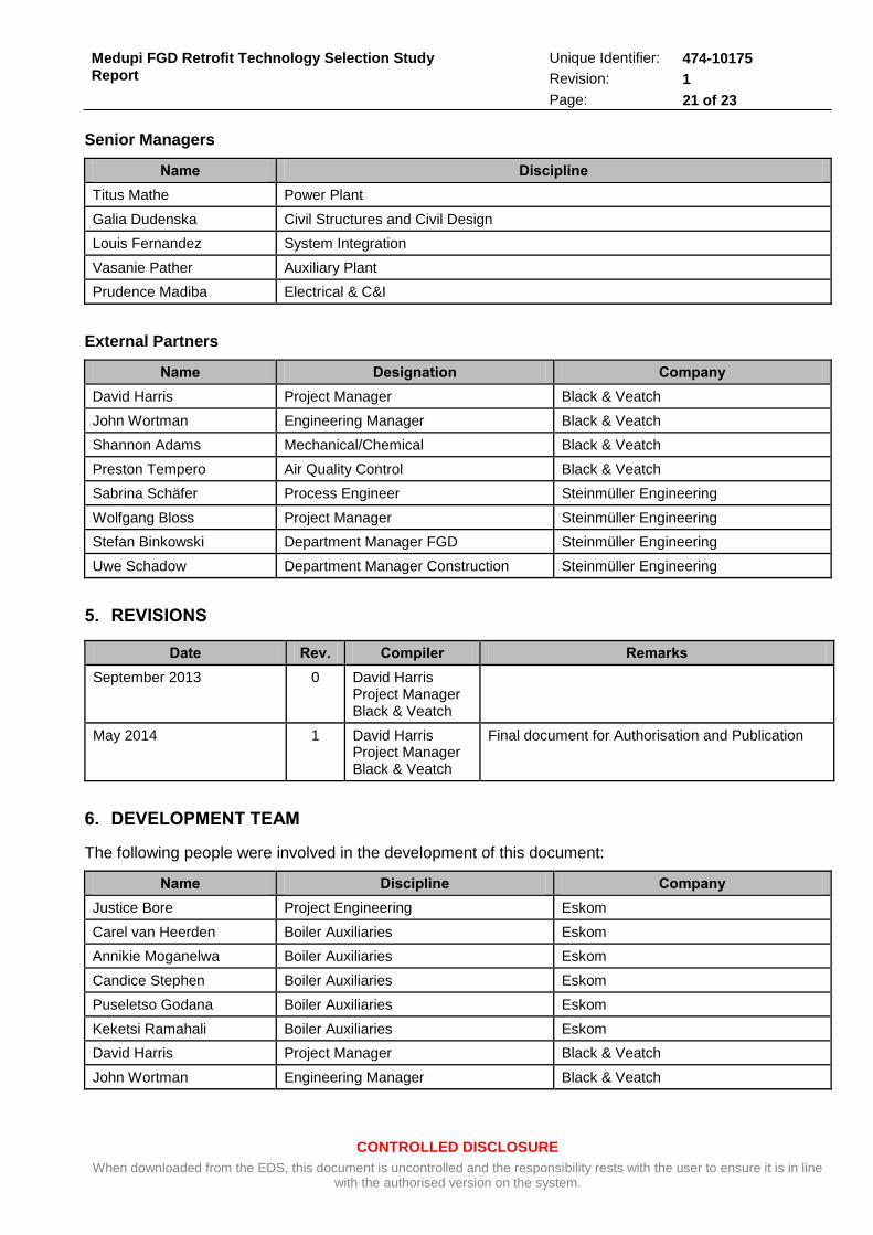
Senior Managers
Name Discipline
Titus Mathe Power Plant
Galia Dudenska Civil Structures and Civil Design
Louis Fernandez System Integration
Vasanie Pather Auxiliary Plant
Prudence Madiba Electrical & C&I
External Partners
Name Designation Company
David Harris Project Manager Black & Veatch
John Wortman Engineering Manager Black & Veatch
Shannon Adams Mechanical/Chemical Black & Veatch
Preston Tempero Air Quality Control Black & Veatch
Sabrina Schäfer Process Engineer Steinmüller Engineering
Wolfgang Bloss Project Manager Steinmüller Engineering
Stefan Binkowski Department Manager FGD Steinmüller Engineering
Uwe Schadow Department Manager Construction Steinmüller Engineering
5. REVISIONS
Date Rev. Compiler Remarks
September 2013 0 David Harris Project Manager Black & Veatch
May 2014 1 David Harris Project Manager Black & Veatch
Final document for Authorisation and Publication
6. DEVELOPMENT TEAM
The following people were involved in the development of this document:
Name Discipline Company
Justice Bore Project Engineering Eskom
Carel van Heerden Boiler Auxiliaries Eskom
Annikie Moganelwa Boiler Auxiliaries Eskom
Candice Stephen Boiler Auxiliaries Eskom
Puseletso Godana Boiler Auxiliaries Eskom
Keketsi Ramahali Boiler Auxiliaries Eskom
David Harris Project Manager Black & Veatch
John Wortman Engineering Manager Black & Veatch

CONTROLLED DISCLOSURE
When downloaded from the EDS, this document is uncontrolled and the responsibility rests with the user to ensure it is in line with the authorised version on the system.
Medupi FGD Retrofit Technology Selection Study
Report
Unique Identifier: 474-10175
Revision: 1
Page: 22 of 23
Name Discipline Company
Shannon Adams Mechanical Black & Veatch
Preston Tempero Air Quality Control Black & Veatch
Wolfgang Bloss Project Manager Steinmüller Engineering
Stefan Binkowski Engineering Management Steinmüller Engineering
Sabrina Schäfer Process Engineer Steinmüller Engineering
Christian Unger Process Engineer Steinmüller Engineering
Uwe Schadow Design Management Steinmüller Engineering
7. ACKNOWLEDGEMENTS
None

CONTROLLED DISCLOSURE
When downloaded from the EDS, this document is uncontrolled and the responsibility rests with the user to ensure it is in line with the authorised version on the system.
Medupi FGD Retrofit Technology Selection Study
Report
Unique Identifier: 474-10175
Revision: 1
Page: 23 of 23
APPENDIX A LIST OF ATTACHMENTS
(The following listed set of Documents are available under separate cover)
Process Flow Diagrams
P06259-R-PFD-005-03 WFGD without Cooler – Worst Coal LS; 96% CaCO3 006265-R-PFD-022 WFGD with Cooler – Worst Coal 96% CaCO3 006265-R-PFD-010-00 Dry / CFB Cluster 1 – Worst Coal 93.07% CaO
Process Area Arrangement Drawings
P06259-Z4010-501-09 WFGD without Cooler 006265-Z4010-XXX WFGD with Cooler 006265-Z4050-001-00 Dry / CFB 006265-Z4050-002-00 Dry / CFB Single Unit Overview
Data Sheets
P06259-S-TAB-0xx-DRAFT Wet FGD / CBF Comparison Overall Data Sheet


![[FGD I3M] Fgd pimnas + solusi](https://img.dokumen.tips/doc/110x75/558a2bccd8b42aca328b459a/fgd-i3m-fgd-pimnas-solusi.jpg)


