Embed Size (px)
Citation preview

Test Report No. 10678.1 No. of Pages 19
Medium Weight Shock and Vibration Test Report
on 1.5” x 1” x 6”Pump with 7.5 HP Motor
for Sims Pump Valve Co., Inc.
Hoboken, NJ
NU LABORATORIES, INC.
312 Old Allerton Road, Annandale, NJ (908)713-9300 WWW.NULABS.COM
E-Mail: [email protected]
30 May 2007
Prepared By Checked By Approved By D. Welaish Sutphen S. Baroczi R.D. McAdoo
30 May 2007
30 May 2007
30 May 2007

NU Laboratories, Inc. Test Report No. 10678.1 a Noise Unlimited Company Page 2
TABLE OF CONTENTS
1. Purpose of Test.............................................................................................................................................3 2. Manufacturer ...............................................................................................................................................3 3. Manufacturer's Type or Model No. ...........................................................................................................3 4. Specifications................................................................................................................................................3 5. Number of Items Tested..............................................................................................................................3 6. Security Classification of Item....................................................................................................................3 7. Date Tests Completed..................................................................................................................................3 8. Test Conducted By.......................................................................................................................................3 9. Test Witnesses ..............................................................................................................................................3 10. Disposition of Test Item...............................................................................................................................4 11. Abstract ........................................................................................................................................................4 12. Shock Test Description................................................................................................................................4 13. Vibration Test Description..........................................................................................................................6 Figures 1-10 ...........................................................................................................................................9 - 18
List of Apparatus .......................................................................................................................................19

NU Laboratories, Inc. Test Report No. 10678.1 a Noise Unlimited Company Page 3
1. PURPOSE OF TEST
The purpose of this tests was to demonstrate that the 1.5” x 1” x 6” Pump with 7.5 HP Motor, hereinafter referred to as “the Pump”, complied with the requirements of MIL-S-901D for a Grade A, Class I, nine (9) blow medium weight shock test and with the requirements of MIL-STD-167-1 when subjected to vibration testing through the frequency range of 4 Hz to 50 Hz in each of the three (3) major axes.
2. MANUFACTURER
Sims Pump Valve Co., Inc. 1314 Park Avenue Hoboken, NJ 07030
3. MANUFACTURER'S TYPE OR MODEL NO.
1.5” x 1” x 6” Pump with 7.5 HP Motor S/N: CR16696_1 (Pump) S/N: K30744-7 (Motor)
4. SPECIFICATIONS
4.1 MILITARY
MIL-S-901D (NAVY) Military Specification, Shock Tests, H.I. (High Impact); Shipboard Machinery, Equipment and Systems, Requirements for, dated 17 March 1989 MIL-STD-167-1 (SHIPS) Military Standards Mechanical Vibrations of Shipboard Equipment, dated 1 May 1974
4.2 SIMS PUMP VALVE CO., INC.
Purchase Order No. 5762
5. NUMBER OF ITEMS TESTED
One (1)
6. SECURITY CLASSIFICATION OF ITEM
Unclassified
7. DATE TESTS COMPLETED
20 April 2007 – Shock 30 April 2007 – Vibration
8. TEST CONDUCTED BY
NU Laboratories, Inc. 312 Old Allerton Road Annandale, NJ 08801 (NAVY Certified Shock Test Facility by NAVSEAINST 9491.1C)
9. TEST WITNESSES
Vladimir Spector, Sims Pump Valve Co., Inc. representative John Franklin, Sims Pump Valve Co., Inc. representative

NU Laboratories, Inc. Test Report No. 10678.1 a Noise Unlimited Company Page 4
10. DISPOSITION OF TEST ITEM
The Pump was returned Sims Pump Valve Co., Inc.
11. ABSTRACT
The Pump was subjected to a total of nine (9) medium weight shock blows in accordance with the referenced test specifications. Visual inspections, performed after each shock blow, revealed no physical damage or discrepancies. Refer to Section 12 for additional information. The Pump was subjected to vibration through the frequency range of 4 Hz through 50 Hz in each of the three (3) major axes in accordance with the referenced test specifications. Visual inspections, performed after each major axis, revealed no discrepancies. Refer to Section 13 for additional information.
12. SHOCK TEST DESCRIPTION
12.1 ACCEPTANCE CRITERIA
In accordance with MIL-STD-901D, the Pump is considered to have failed the shock test if any portion of the equipment comes adrift or otherwise becomes a hazard to personnel, or equipment is not able to perform its Grade A specified function due to performance degradation.
12.2 TEST SETUP
Upon receipt a visual inspection of the Pump revealed no obvious physical damage or discrepancy. The Pump was weighed using a portable platform scale and the weight was recorded in the test log. The weight of the Pump was 375 pounds. The Pump was bolted to a 48” x 48” x 1½” transition plate using four (4) ¾”-10 Grade 5 bolts torqued to 260 ft-lbs. Two (2) half-rails were attached to the transition plate and the entire assembly was secured to fixture Figure 13 of MIL-S-901D on the medium weight shock machine, oriented in the first major axis of test. The total weight on the anvil table was 1954.5 pounds. Refer to Table 1 for the medium weight shock test weights and Figure 1 for the photograph of the test setup.
Table 1: Medium Weight Shock Test Weights
Pump 375 lbs 48” x 48” x 1½” Transition Plate 933 lbs Four (4) ¾”-10 Grade 5 Bolts 4 lbs Suction Dummy Load 20 lbs Discharge Dummy Load 11.5 lbs Two (2) Half Rails 166 lbs Eight (8) Half Rail Shoes 32 lbs Six (6) T-Blocks with Hardware 24 lbs Six (6) ½” Spacers 9 lbs Fixture Figure 13 of MIL-S-901D 380 lbs Fixture Figure 16 of MIL-S-901D 1470 lbs Total Weight Fixture Figure 13 1954.5 lbs Total Weight Fixture Figure 16 3044.5 lbs
12.3 TEST CONDITIONS
The Pump was energized with 460V, 3-phase, 60 Hz power throughout shock testing. During Group I and Group III blows, identified as “CONDITION A”, the Pump was operational and pressurized to 63 psig. During Group II blows, identified as “CONDITION B”, the Pump was non-operational and flooded.

NU Laboratories, Inc. Test Report No. 10678.1 a Noise Unlimited Company Page 5
12.4 BLOW #1 – CONDITION A
12.4.1 Conditions: Vertical Axis, 1’ hammer height, Group #I, 3” anvil table travel, fixture Figure 13 of the referenced specifications.
12.4.2 Observations: A post-blow visual inspection revealed no obvious physical damage or discrepancies. 12.4.3 Action: The mounting bolts were retorqued and testing was continued.
12.5 BLOW #2 – CONDITION B
12.5.1 Conditions: Vertical Axis, 2’ hammer height, Group #II, 3” anvil table travel, fixture Figure 13 of the referenced specifications.
12.5.2 Observations: A post-blow visual inspection revealed no obvious physical damage or discrepancies. 12.5.3 Action: Testing was continued.
12.6 BLOW #3 – CONDITION A
12.6.1 Conditions: Vertical Axis, 2’ hammer height, Group #III, 1.5” anvil table travel, fixture Figure 13 of the referenced specifications.
12.6.2 Observations: A post-blow visual inspection revealed no obvious physical damage or discrepancies. 12.6.3 Action: Testing was continued.
The entire assembly was removed from fixture Figure 13 of MIL-S-901D and attached to fixture Figure 16 of MIL-S-901D, oriented with the side of the Pump down. The total weight on the anvil table was 3044.5 pounds. Refer to Table 1 for the test weights and Figure 1 for the photograph of the test setup.
12.7 BLOW #4 – CONDITION A
12.7.1 Conditions: 30° Side Down, 1.5’ hammer height, Group #I, 3” anvil table travel, fixture Figure 16 of the referenced specifications.
12.7.2 Observations: A post-blow visual inspection revealed no obvious physical damage or discrepancies. 12.7.3 Action: Testing was continued.
12.8 BLOW #5 – CONDITION B
12.8.1 Conditions: 30° Side Down, 2.5’ hammer height, Group #II, 3” anvil table travel, fixture Figure 16 of the referenced specifications.
12.8.2 Observations: A post-blow visual inspection revealed no obvious physical damage or discrepancies. 12.8.3 Action: Testing was continued.
12.9 BLOW #6 – CONDITION A
12.9.1 Conditions: 30° Side Down, 2.5’ hammer height, Group #III, 1.5” anvil table travel, fixture Figure 16 of the referenced specifications.
12.9.2 Observations: A post-blow visual inspection revealed no obvious physical damage or discrepancies. 12.9.3 Action: Testing was continued.
The entire assembly was removed from fixture Figure 16, rotated 90°, and reattached to fixture Figure 16 of MIL-S-901D with the front of the Pump facing down. The total weight on the anvil table remained 3044.5 pounds. Refer to Figure 1 for the photograph of the test setup.
12.10 BLOW #7 – CONDITION A
12.10.1 Conditions: 30° Front Down, 1.5’ hammer height, Group #I, 3” anvil table travel, fixture Figure 16 of the referenced specifications.
12.10.2 Observations: A post-blow visual inspection revealed no obvious physical damage or discrepancies. 12.10.3 Action: Testing was continued.

NU Laboratories, Inc. Test Report No. 10678.1 a Noise Unlimited Company Page 6
12.11 BLOW #8 – CONDITION B
12.11.1 Conditions: 30° Front Down, 2.5’ hammer height, Group #II, 3” anvil table travel, fixture Figure 16 of the referenced specifications.
12.11.2 Observations: A post-blow visual inspection revealed no obvious physical damage or discrepancies. 12.11.3 Action: Testing was continued.
12.12 BLOW #9 – CONDITION A
12.12.1 Conditions: 30° Front Down, 2.5’ hammer height, Group #III, 1.5” anvil table travel, fixture Figure 16 of the referenced specifications.
12.12.2 Observations: A post-blow visual inspection revealed no obvious physical damage or discrepancies. 12.12.3 Action: Testing was completed.
Refer to the Factory Test Record, Figure 2, and the Shock Acceptance Form, Figure 3, for additional information.
13. VIBRATION TEST DESCRIPTION
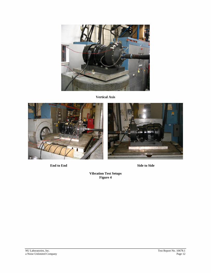
Upon completion of shock testing, the Pump was removed from the medium weight shock machine and attached to the vibration machine oriented in the first major axis of test. Refer to Figure 4 for photographs of the test setups. One (1) accelerometer was attached to the fixture plate and one (1) accelerometer was attached to the top of the Pump discharge port, oriented in the direction of vibration, to aid in the detection of response prominences. The Pump was flooded with water, energized with 460 VAC, three (3) phase, 60 Hz power and operating with the discharge pressure adjusted to 63 psig throughout the vibration test
13.1 FIRST MAJOR AXIS OF VIBRATION (VERTICAL)
13.1.1 Exploratory Vibration The Pump was vibrated from 4 Hz through 33 Hz with a vibration input of 0.020 ± 0.004 inches (double amplitude) to determine response prominences and from 34 Hz through 50 Hz with a vibration input of 0.006 + 0.000/-0.002 (double amplitude) to determine response prominences. The change in frequency was made in discrete intervals of 1 Hz and the vibration was maintained at each frequency for approximately 15 seconds. No response prominences were noted. The table input vibration levels and the accelerometer output vibration levels at each frequency were recorded on the Vibration Test Data Sheet, Figure 5.
13.1.2 Variable Frequency Vibration
The Pump was vibrated from 4 Hz to 50 Hz with input amplitudes as shown in Table 2. The change in frequency was made in discrete intervals of 1 Hz and the vibration was maintained at each frequency for a period of five (5) minutes. No obvious physical damage, leakage or loss in pressure was noted. The table input vibration levels and the accelerometer output vibration levels at each frequency were recorded on the Vibration Test Data Sheet, Figure 5.

NU Laboratories, Inc. Test Report No. 10678.1 a Noise Unlimited Company Page 7
Table 2: Variable Frequency Test Amplitudes
FREQUENCY (Hz)
INPUT INCHES (DOUBLE AMPLITUDE)
4 – 15 Hz 0.060 ± 0.012 16 – 25 Hz 0.040 ± 0.008 26 – 33 Hz 0.020 ± 0.004 34 – 40 Hz 0.010 ± 0.002 41 – 50 Hz 0.006 + 0.000
-0.002
13.1.3 Endurance Vibration The endurance vibration was performed at the frequency of 50 Hz for a period of two (2) hours. Upon the completion of the two (2) hour dwell, a visual inspection revealed no obvious physical damage, leakage or loss in pressure.
13.2 SECOND MAJOR AXIS OF VIBRATION (END TO END)
13.2.1 Exploratory Vibration The Pump was vibrated from 4 Hz through 33 Hz with a vibration input of 0.020 ± 0.004 inches (double amplitude) to determine response prominences and from 34 Hz through 50 Hz with a vibration input of 0.006 + 0.000/-0.002 (double amplitude) to determine response prominences. The change in frequency was made in discrete intervals of 1 Hz and the vibration was maintained at each frequency for approximately 15 seconds. No response prominences were noted. The table input vibration levels and the accelerometer output vibration levels at each frequency were recorded on the Vibration Test Data Sheet, Figure 6.
13.2.2 Variable Frequency Vibration
The Pump was vibrated from 4 Hz to 50 Hz with input amplitudes as shown in Table 2. The change in frequency was made in discrete intervals of 1 Hz and the vibration was maintained at each frequency for a period of five (5) minutes. No obvious physical damage, leakage or loss in pressure was noted. The table input vibration levels and the accelerometer output vibration levels at each frequency were recorded on the Vibration Test Data Sheet, Figure 6
13.2.3 Endurance Vibration
The endurance vibration was performed at the frequency of 50 Hz for a period of two (2) hours. Upon the completion of the two (2) hour dwell, a visual inspection revealed no obvious physical damage, leakage or loss in pressure.
13.3 THIRD MAJOR AXIS OF VIBRATION (SIDE TO SIDE)
13.3.1 Exploratory Vibration The Pump was vibrated from 4 Hz through 33 Hz with a vibration input of 0.020 ± 0.004 inches (double amplitude) to determine response prominences and from 34 Hz through 50 Hz with a vibration input of 0.006 + 0.000/-0.002 (double amplitude) to determine response prominences. The change in frequency was made in discrete intervals of 1 Hz and the vibration was maintained at each frequency for approximately 15 seconds. No response prominences were noted. The table input vibration levels and the accelerometer output vibration levels at each frequency were recorded on the Vibration Test Data Sheet, Figure 7.

NU Laboratories, Inc. Test Report No. 10678.1 a Noise Unlimited Company Page 8
13.3.2 Variable Frequency Vibration The Pump was vibrated from 4 Hz to 50 Hz with input amplitudes as shown in Table 2. The change in frequency was made in discrete intervals of 1 Hz and the vibration was maintained at each frequency for a period of five (5) minutes. No obvious physical damage, leakage or loss in pressure was noted. The table input vibration levels and the accelerometer output vibration levels at each frequency were recorded on the Vibration Test Data Sheet, Figure 7.
13.3.3 Endurance Vibration
The endurance vibration was performed at the frequency of 50 Hz for a period of two (2) hours. Upon the completion of the two (2) hour dwell an inspection was performed which revealed no obvious physical damage, leakage or loss in pressure. Refer to the Vibration Test Data Sheets, Figures 5 through 7, and the Vibration Plots, Figures 8 through 10, for additional information.

NU Laboratories, Inc. Test Report No. 10678.1 a Noise Unlimited Company Page 9
Vertical Axis
30° Side Down 30° Front Down
Shock Test Setups Figure 1

NU Laboratories, Inc. Test Report No. 10678.1 a Noise Unlimited Company Page 10
Factory Test Record Figure 2

NU Laboratories, Inc. Test Report No. 10678.1 a Noise Unlimited Company Page 11
MIL-S-901D: SHOCK ACCEPTANCE FORM
1. The item identified below has met the requirements of Military Specification MIL-S-901, based upon:
⌧ Shock testing of the item identified below
Previous shock testing of an item similar to the item identified below (shock test extension)
Previous shock testing of an item identical to the item identified below (shock test extension)
2. Item (Nomenclature) Pump
3. Item (Description) 1.5” x 1” x 6” Pump with 7.5 HP Motor
4. Tested For Sims Pump Valve Co., Inc.
5. M/N: 6. S/N: CR16696_1 (Pump); K30744-7 (Motor)
7. Dwg. Number 8. Revision and Date
9. Military Specification MIL-S-901D
10. Ship 11. Service
12. Contract No.
13. Shock Test Facility NU Laboratories, Inc.
14. Report No. 10678.1
15. Previous Shock test approval reference (if this form conveys shock test Extension approval)
16. Test Category 1 Lightweight Medium weight 1 Heavyweight
17. Shock Grade A 1 B
18. Equipment Class I 1 II 1 III
19. Shock Test Type A 1 B 1 C
20. Mounting Location Deck 1Hull 1 Shell 1 Wetted-Surface
21. Shipboard mounting plane represented during shock test:
Base 1Front or Face Back 1 Top 1 Combination 1 Other
22. Mounting orientation of item relative to ship’s fore-and-aft axis (for medium weight and heavyweight test items only): Unrestricted
23. Approval Limitations:
24. Approved. 25 April 2007
Authorized Signature Approval Activity Date
Shock Acceptance Form Figure 3
NU Laboratories, Inc. Test Report No. 10678.1 a Noise Unlimited Company Page 12
Vertical Axis
End to End Side to Side
Vibration Test Setups Figure 4

NU Laboratories, Inc. Test Report No. 10678.1 a Noise Unlimited Company Page 13
Vibration Test Data Sheet Figure 5

NU Laboratories, Inc. Test Report No. 10678.1 a Noise Unlimited Company Page 14
Vibration Test Data Sheet Figure 6

NU Laboratories, Inc. Test Report No. 10678.1 a Noise Unlimited Company Page 15
Vibration Test Data Sheet Figure 7

NU Laboratories, Inc. Test Report No. 10678.1 a Noise Unlimited Company Page 16
Exploratory
Variable and Endurance
Vibration Plots Vertical Axis
Figure 8

NU Laboratories, Inc. Test Report No. 10678.1 a Noise Unlimited Company Page 17
Exploratory
Variable and Endurance
Vibration Plots End to End
Figure 9

NU Laboratories, Inc. Test Report No. 10678.1 a Noise Unlimited Company Page 18
Exploratory
Variable and Endurance
Vibration Plots Side to Side Figure 10

NU Laboratories, Inc. Test Report No. 10678.1 a Noise Unlimited Company Page 19
LIST OF APPARATUS
DESCRIPTION MANUFACTURER MODEL NO. SERIAL NO. CAL DATE DUE DATE
Platform Scale Fairbanks Morse 1124A G-511379 09/19/06 09/19/07
Digital Scale Industrial Sales TI-500SSB-5K 5019011000018 09/19/06 09/19/07
Balance Scale Ohaus 1225 EL-330 09/19/06 09/19/07
Torque Wrench CDI 2503MFRMH 0499200127 03/22/07 03/22/08
Torque Wrench Utica TCI-150FRN MD6973 09/11/06 09/11/07
Torque Wrench CDI 752MFRMH 1002602828 01/24/07 01/24/08 0-100 Pressure
Gauge Weksler GP2-16-3 1001 11/03/06 11/03/07
Medium Weight Shock Machine New England Trawler 10-T-3351-C N/A Functional
Vibration Machine Unholtz T1000.20 357 Functional
Vibration Controller Data Physics DP550 3186 01/11/07 01/11/08
Power Supply Endevco 4222 EL393 06/14/06 06/14/07
Charge Amplifier Endevco 2721B BR34 06/14/06 06/14/07
Charge Amplifier Endevco 2721B BR16 06/14/06 06/14/07
Accelerometer Endevco 2221D EY62 03/05/07 03/05/08
Accelerometer Endevco 2221D EY55 03/05/07 03/05/08
All calibrations are traceable to the National Institute of Standards and Technology. Procedures satisfy the requirements set forth in MIL-STD-45662 or ANSI/NCSL Z540-1.
Calibration records are on file at NU Laboratories, Inc.
All weights and scales are traceable to the State of NJ Office of Weights and Measures
(NJSA 51:1-61; 75; NJAC 13:47E-1.2)