Embed Size (px)
Citation preview

EDMS NO. REV. VALIDITY
1734868 0.2
REFERENCE
Date: 9.11.2016
CERN CH1211 Geneva 23 Switzerland
Project description
MEDICIS FRONTEND
Summary
This document is intended to describe the functionalities and the operation principle of the
MEDICIS Frontend. It presents the definition of the equipment, a budget estimate, the need
for human resources and planning.
MEDICIS Work Package 9
DOCUMENT PREPARED BY: DOCUMENT CHECKED BY: DOCUMENT APPROVED BY:
S.Marzari
A-P.Bernardes Y.Martinez
R.Catherall
K.Kershaw
T.Stora
Distribution list:
Ch.Mitifiot, W.Andreazza, J.Ferreira, V.Barozier, A.Broche, J-L.Grenard, J.Parra-Lopez, A.Dorsival,
P.Fernier

REFERENCE EDMS NO. REV. VALIDITY
- 1734868 0.1 DRAFT
Page 2 of 31
HISTORY OF CHANGES
REV. NO. DATE PAGES DESCRIPTIONS OF THE CHANGES
0.1
0.2
16.11.2016
21.11.2017
All
First Draft
Various updates

REFERENCE EDMS NO. REV. VALIDITY
- 1734868 0.1 DRAFT
Page 3 of 31
TABLE OF CONTENTS
1. SCOPE OF THE MEDICIS FRONTEND .............................................. 4
1.1 Introduction ...................................................................................... 4
1.2 Main constraints ................................................................................ 5
1.2.1 Radiation resistance ........................................................................................................................................... 6
1.2.2 Material choices .................................................................................................................................................... 6
1.2.3 Interfaces ................................................................................................................................................................. 7
2. TECHNICAL DESCRIPTION............................................................. 9
2.1 Welded frame and 3 point alignment foots ...................................... 10
2.2 Vacuum system ............................................................................... 13
2.2.1 Vacuum sectors .................................................................................................................................................. 14
2.2.2 Vacuum operation ............................................................................................................................................ 15
2.3 Coupling table ................................................................................. 16
2.4 Electrical insulations ....................................................................... 17
2.5 Water cooling .................................................................................. 18
2.6 Beam optics elements ..................................................................... 19
2.6.1 Extraction electrode ........................................................................................................................................ 20
2.6.2 X-y electrostatic deflectors ........................................................................................................................... 21
2.6.3 Einzel lens ............................................................................................................................................................ 21
2.6.4 Beam optics optimisation .............................................................................................................................. 22
3. FRONTEND CONTROL .................................................................. 24
3.1 Frontend control functions .............................................................. 26
3.2 Calibrations functions ..................................................................... 27
3.3 Interlocks between Frontend control and other control systems .... 27
4. DELIVERABLES AND INTERFACES WITH OTHER WP .................... 28
4.1 Deliverables .................................................................................... 28
4.2 Interfaces with other work packages .............................................. 28
5. SAFETY ASPECTS (to be completed by Ana Paula) ............................ 29
6. PLANNING ................................................................................... 30
7. BUDGET ESTIMATE and MANPOWER............................................ 31
7.1 Budget ............................................................................................ 31
7.2 Manpower ....................................................................................... 31

REFERENCE EDMS NO. REV. VALIDITY
- 1734868 0.1 DRAFT
Page 4 of 31
1. SCOPE OF THE MEDICIS FRONTEND
1.1 Introduction
The MEDICIS Frontend is an electrostatic accelerator (max. 60kV) for ionized atoms
dedicated to Nuclear Medicine research. It is part of the MEDICIS beam line composed
by:
the Target and ion source,
the Frontend,
the magnet separator,
the beam instrumentation box and
the isotope collection system.
Due to the high level of radioactivity (see report EDMS 1291509), it is installed into the
bunker 179-R-027 behind 670mm magnetite concrete walls and heavy 400mm iron
doors in order to protect operators working into the MEDICIS laboratory 179-R-025.
The coupling table has to be compatible with of the actual ISOLDE target base design
that will give us the flexibility to use either ISOLDE or MEDICIS targets.
All the beam line is under vacuum. In order to minimise the pumping volume sent to
the gas storage tanks located into the vacuum services room, the dimensions of the
MEDICIS Frontend is reduced compared with the standard ISOLDE Frontend. The most
relevant difference with the ISOLDE Frontend is that the electrostatic set of quadrupoles
are replaces by an Einzel lens system more adapted to the reduced beam line dimension.
REFERENCE EDMS NO. REV. VALIDITY
- 1734868 0.1 DRAFT
Page 5 of 31
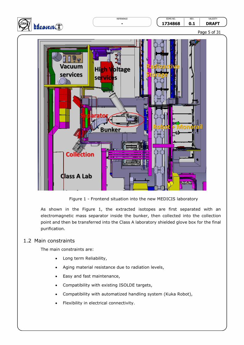
Figure 1 - Frontend situation into the new MEDICIS laboratory
As shown in the Figure 1, the extracted isotopes are first separated with an
electromagnetic mass separator inside the bunker, then collected into the collection
point and then be transferred into the Class A laboratory shielded glove box for the final
purification.
1.2 Main constraints
The main constraints are:
Long term Reliability,
Aging material resistance due to radiation levels,
Easy and fast maintenance,
Compatibility with existing ISOLDE targets,
Compatibility with automatized handling system (Kuka Robot),
Flexibility in electrical connectivity.

REFERENCE EDMS NO. REV. VALIDITY
- 1734868 0.1 DRAFT
Page 6 of 31
1.2.1 Radiation resistance
At MEDICIS the level of radiation is a fraction of what we have into the ISOLDE target
area because there is no interaction with the proton beam inside the MEDICIS area. The
target is first activated on the irradiation point between the beam dump and the ISOLDE
Frontend into the ISOLDE target area, then the target is transferred with the rail
conveyor system (RCS) to the decay point behind a shielding. When the radiation level
at 40 cm decrease below 1 Sv/h, it is allowed to install it (with the Kuka robot) on the
MEDICIS Frontend.
The accumulated dose on the MEDICIS Frontend at 40 cm during one year MEDICIS
operation for 30 targets, each target operated during 2 days can be estimated to 1.5
kGy. In comparison at ISOLDE during one year at 40 cm we have more than 2 MGy.
See report EDMS 1291509 for more information.
Figure 2 - dose rate mapping in µSv/h
1.2.2 Material choices
The MEDICIS Frontend is an adaptation of a standard ISOLDE Frontend, so we will use
the same materials for convenience and compatibility even if due to lower radiation
constraints some materials (i.e. the all metal seals or the main Al2O3 insulator) could
be replaced with more practical alternatives like elastomers o-rings (Viton® or EPDM)
or plastics like PEEK or Vespel® for insulators.
The main used material are: (for ISOLDE Frontend)
Aluminum Alloy AW6082 for frame, vacuum chambers
PEEK 1000 for external insulators

REFERENCE EDMS NO. REV. VALIDITY
- 1734868 0.1 DRAFT
Page 7 of 31
Aluminum Helicoflex for vacuum sealing
EPDM rubber for vacuum sealing
Al2O3 for main vacuum insulator
Titanium TA6V for extraction electrode
Stainless Steel quality A4 for screws and fittings
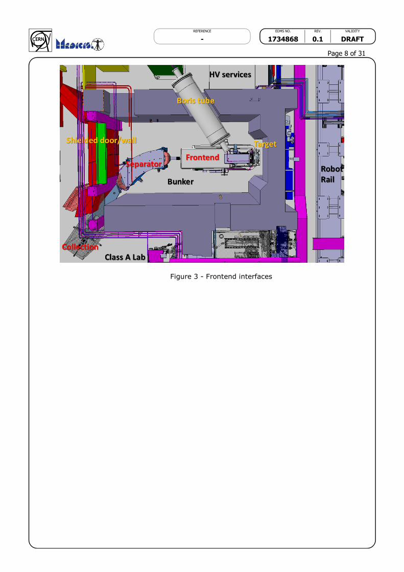
1.2.3 Interfaces
The interfaces with the Frontend are: (Figures 3, 4 and 5)
Foots supports on the floor (3x)
The coupling table for the target coupling/uncoupling (this operation is
completely automatized and the target handling is done with an adapted
industrial Kuka Robot)
The connection with the magnet mass separator (with a bellow flange)
The connections with high voltage services through the Boris tube including:
o Power,
o Measure,
o Water cooling,
o Compressed air
The connections with low voltage services
o Beam optics,
o Beam diagnostic,
o Compressed air,
o Water cooling
o Vacuum devices
REFERENCE EDMS NO. REV. VALIDITY
- 1734868 0.1 DRAFT
Page 8 of 31
Figure 3 - Frontend interfaces
REFERENCE EDMS NO. REV. VALIDITY
- 1734868 0.1 DRAFT
Page 9 of 31
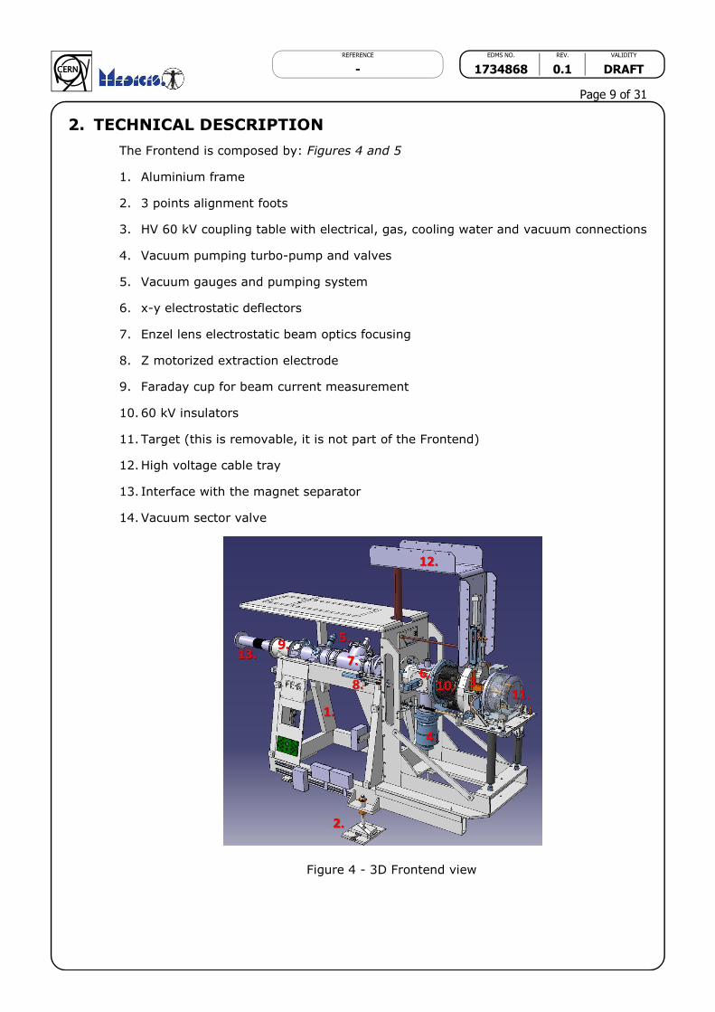
2. TECHNICAL DESCRIPTION
The Frontend is composed by: Figures 4 and 5
1. Aluminium frame
2. 3 points alignment foots
3. HV 60 kV coupling table with electrical, gas, cooling water and vacuum connections
4. Vacuum pumping turbo-pump and valves
5. Vacuum gauges and pumping system
6. x-y electrostatic deflectors
7. Enzel lens electrostatic beam optics focusing
8. Z motorized extraction electrode
9. Faraday cup for beam current measurement
10. 60 kV insulators
11. Target (this is removable, it is not part of the Frontend)
12. High voltage cable tray
13. Interface with the magnet separator
14. Vacuum sector valve
Figure 4 - 3D Frontend view

REFERENCE EDMS NO. REV. VALIDITY
- 1734868 0.1 DRAFT
Page 10 of 31
Figure 5 - 2D section view – in yellow changes respect to ISOLDE Frontend
2.1 Welded frame and 3 point alignment foots
The frame for MEDICIS Frontend is the same as used in Frontend 6 generation actually
in operation at ISOLDE. It is composed by a fixed part (rear) and a removable part
(front). It is design to be rigid enough to guaranty the stability and the alignment.
The frame is made in aluminium alloy AW 6082, this alloy guarantee a good stability
and grain homogeneity after the thermal stresses induced by the aluminium profiles
welding.
In Figure 6 you can see the possibility to uncouple the removable part from the fixed
part (just in case of major issue). The Target in red (not part of the Frontend) is changed
each one or two weeks depending of the aging and the typology of the experiment.
REFERENCE EDMS NO. REV. VALIDITY
- 1734868 0.1 DRAFT
Page 11 of 31
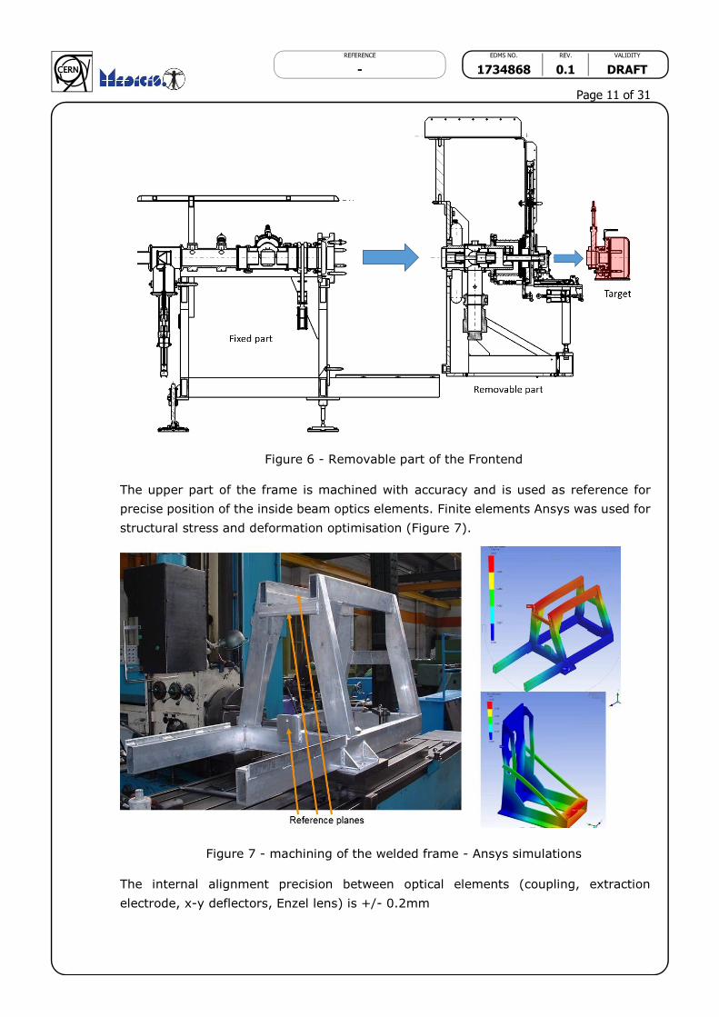
Figure 6 - Removable part of the Frontend
The upper part of the frame is machined with accuracy and is used as reference for
precise position of the inside beam optics elements. Finite elements Ansys was used for
structural stress and deformation optimisation (Figure 7).
Figure 7 - machining of the welded frame - Ansys simulations
The internal alignment precision between optical elements (coupling, extraction
electrode, x-y deflectors, Enzel lens) is +/- 0.2mm

REFERENCE EDMS NO. REV. VALIDITY
- 1734868 0.1 DRAFT
Page 12 of 31
The external alignment precision between Frontend and other beam elements (magnet
separator) is +/- 0.5mm
The 3 points foots (Figure 8) are used to align the Frontend with the rest of the beam
line (magnet). They allow to adjust the optical axle without inducing any constraints
into the Frontend frame. The system is using 3 spherical points in contact with a cone
(rear side), with a V and with a flat surface (front side).
Figure 8 - 3 foots alignment system
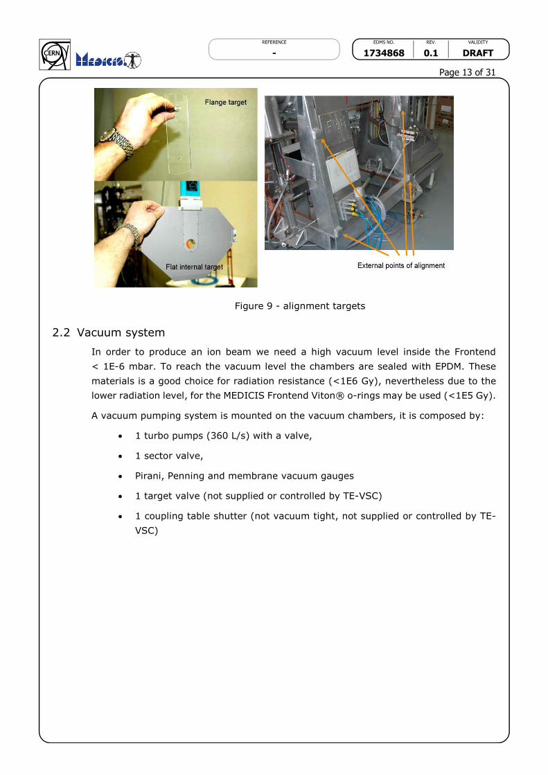
To set the correct position of the Frontend we have two possibilities: see Figure 9
Alignment with optical targets placed directly on the beam optics axle
Alignment with external points placed on the frame and references on the
surrounding environment
REFERENCE EDMS NO. REV. VALIDITY
- 1734868 0.1 DRAFT
Page 13 of 31
Figure 9 - alignment targets
2.2 Vacuum system
In order to produce an ion beam we need a high vacuum level inside the Frontend
< 1E-6 mbar. To reach the vacuum level the chambers are sealed with EPDM. These
materials is a good choice for radiation resistance (<1E6 Gy), nevertheless due to the
lower radiation level, for the MEDICIS Frontend Viton® o-rings may be used (<1E5 Gy).
A vacuum pumping system is mounted on the vacuum chambers, it is composed by:
1 turbo pumps (360 L/s) with a valve,
1 sector valve,
Pirani, Penning and membrane vacuum gauges
1 target valve (not supplied or controlled by TE-VSC)
1 coupling table shutter (not vacuum tight, not supplied or controlled by TE-
VSC)
REFERENCE EDMS NO. REV. VALIDITY
- 1734868 0.1 DRAFT
Page 14 of 31
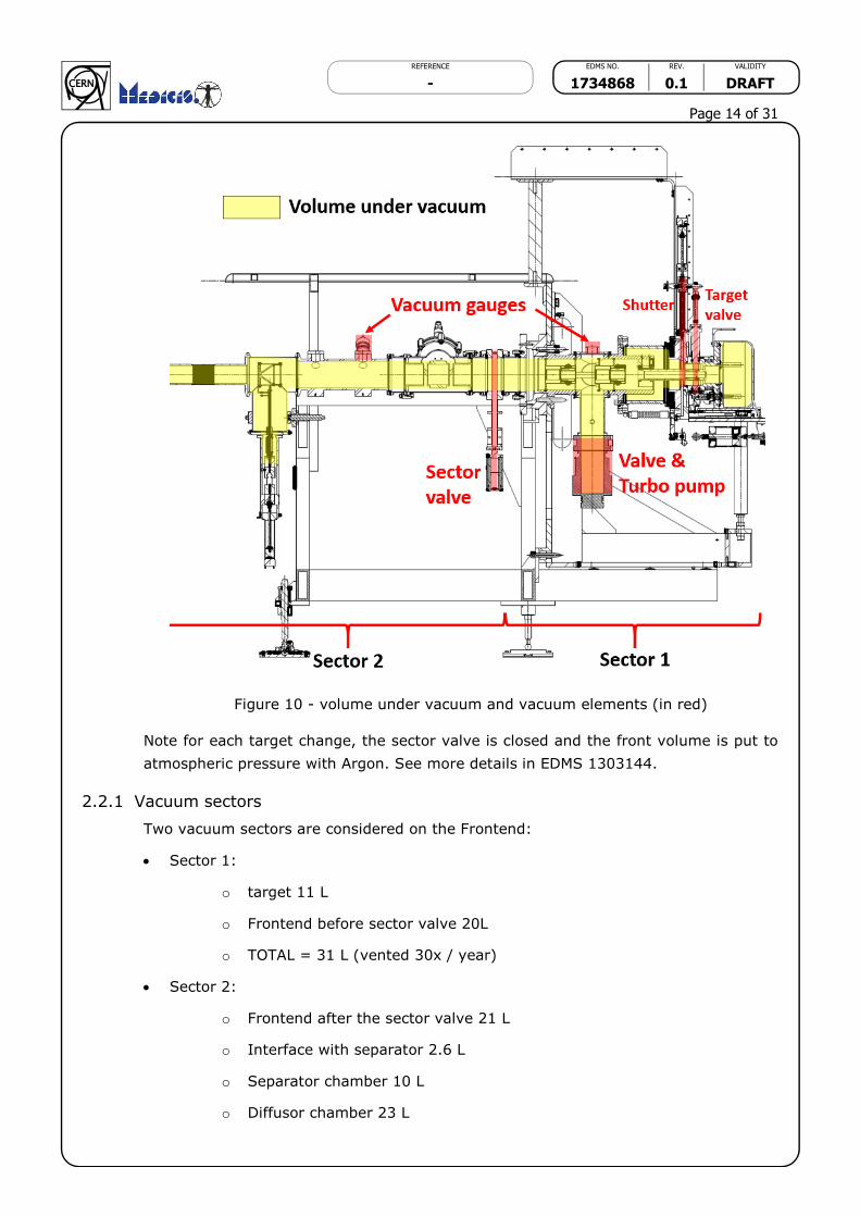
Figure 10 - volume under vacuum and vacuum elements (in red)
Note for each target change, the sector valve is closed and the front volume is put to
atmospheric pressure with Argon. See more details in EDMS 1303144.
2.2.1 Vacuum sectors
Two vacuum sectors are considered on the Frontend:
Sector 1:
o target 11 L
o Frontend before sector valve 20L
o TOTAL = 31 L (vented 30x / year)
Sector 2:
o Frontend after the sector valve 21 L
o Interface with separator 2.6 L
o Separator chamber 10 L
o Diffusor chamber 23 L

REFERENCE EDMS NO. REV. VALIDITY
- 1734868 0.1 DRAFT
Page 15 of 31
o Beam instrumentation box ~20 L (has to be confirmed by the study)
o TOTAL = 77 L (vented 2x / year)
2.2.2 Vacuum operation
Here we consider only the operation of sector 1. Sector 2 (separator) and sector 3
(isotope collection system) are normally always under vacuum.
Sequences of operation:
When a new target is placed on the coupling table sector 1 is vented with Argon and
the shutter valve closed
Target is clamped on the Frontend (FE control)
FE control allows Water cooling starts
Open shutter and target valve (FE control)
FE control allows start pumping (to vacuum control)
The operator can start sector 1 pumping (vacuum control)
When Sector Pump OK the operator can open sector 2 valve (vacuum control)
Conditions for Target heating: vacuum < 1E-4 mbar
Conditions for High voltage: vacuum < 1E-5 mbar
During operation:
o If vacuum >1E-4 mbar => stop target heating
o If vacuum > 1E-5 mbar => stop high voltage
When operation is finished :
o The operator close sector 2 valve (vacuum control)
o High voltage is switched off
o Target heating is switched off
o After a delay of 1h30’ (to be confirmed) water cooling is switched off and
purged and Pump off allow
The operator ask to vent (argon) sector 2 (vacuum control)
When signal Vent OK the vacuum control allows to close the shutter and target valve
(to FE control)
The operator ask to close the shutter and target valve (FE control)
When signal Vent OK the vacuum control allows target unclamping (to FE control)
The operator ask for target uncoupling (FE control)
End of cycle
REFERENCE EDMS NO. REV. VALIDITY
- 1734868 0.1 DRAFT
Page 16 of 31
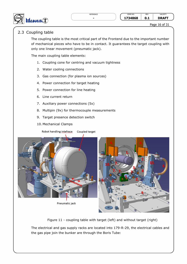
2.3 Coupling table
The coupling table is the most critical part of the Frontend due to the important number
of mechanical pieces who have to be in contact. It guarantees the target coupling with
only one linear movement (pneumatic jack).
The main coupling table elements:
1. Coupling cone for centring and vacuum tightness
2. Water cooling connections
3. Gas connection (for plasma ion sources)
4. Power connection for target heating
5. Power connection for line heating
6. Line current return
7. Auxiliary power connections (5x)
8. Multipin (9x) for thermocouple measurements
9. Target presence detection switch
10. Mechanical Clamps
Figure 11 - coupling table with target (left) and without target (right)
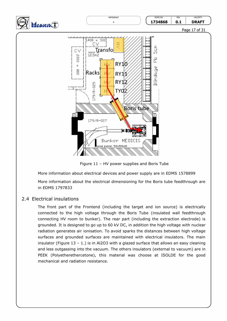
The electrical and gas supply racks are located into 179-R-29, the electrical cables and
the gas pipe join the bunker are through the Boris Tube:
REFERENCE EDMS NO. REV. VALIDITY
- 1734868 0.1 DRAFT
Page 17 of 31
Figure 11 – HV power supplies and Boris Tube
More information about electrical devices and power supply are in EDMS 1578899
More information about the electrical dimensioning for the Boris tube feedthrough are
in EDMS 1797833
2.4 Electrical insulations
The front part of the Frontend (including the target and ion source) is electrically
connected to the high voltage through the Boris Tube (insulated wall feedthrough
connecting HV room to bunker). The rear part (including the extraction electrode) is
grounded. It is designed to go up to 60 kV DC, in addition the high voltage with nuclear
radiation generates air ionisation. To avoid sparks the distances between high voltage
surfaces and grounded surfaces are maintained with electrical insulators. The main
insulator (Figure 13 – 1.) is in Al2O3 with a glazed surface that allows an easy cleaning
and less outgassing into the vacuum. The others insulators (external to vacuum) are in
PEEK (Polyetherethercetone), this material was choose at ISOLDE for the good
mechanical and radiation resistance.

REFERENCE EDMS NO. REV. VALIDITY
- 1734868 0.1 DRAFT
Page 18 of 31
Figure 12 - Frontend 60 kV insulators in yellow
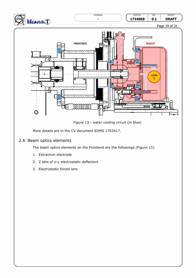
2.5 Water cooling
To guarantee the safe operational temperature, the target and coupling table flange
shall be water-cooled. Due to the presence of high voltage on the coupling table, the
water is demineralized through a dedicated system and maintained to low temperature
with a chiller placed on the roof of the building 179.
This autonomous device allows having water-cooling even during the shutdown when
the cooled water network is stop for annual maintenance.
The water skid device is under the responsibility of the CV group and it is located into
the CV room 170/1-23. The water cooling system guarantee the cooling also of the
separator magnet.
On the Frontend two flanges are cooled and on Target one flange and the three main
power feedthroughs (see Figure 14). These two elements (Frontend and Target) are
connected in a serial loop, electrical insulation is done with an insulating portion of piping
located on the Frontend frame.
REFERENCE EDMS NO. REV. VALIDITY
- 1734868 0.1 DRAFT
Page 19 of 31
Figure 13 - water cooling circuit (in blue)
More details are in the CV document EDMS 1703417.
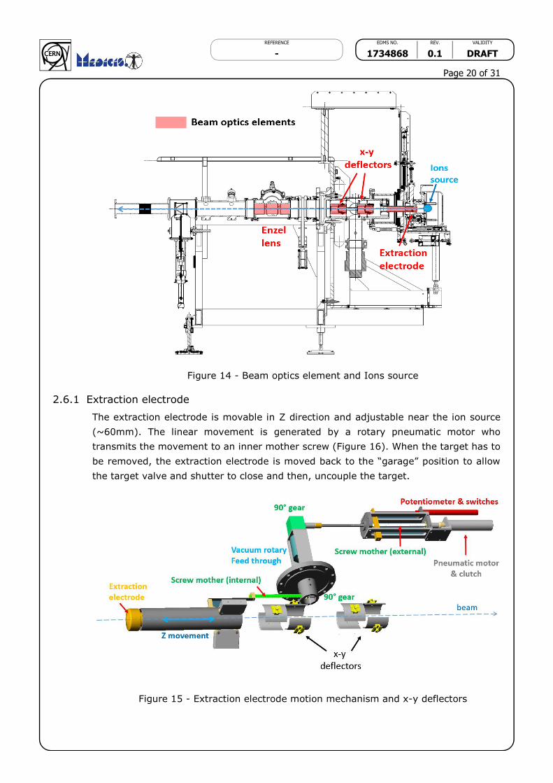
2.6 Beam optics elements
The beam optics elements on the Frontend are the followings (Figure 15)
1. Extraction electrode
2. 2 sets of x-y electrostatic deflectors
3. Electrostatic Einzel lens
REFERENCE EDMS NO. REV. VALIDITY
- 1734868 0.1 DRAFT
Page 20 of 31
Figure 14 - Beam optics element and Ions source
2.6.1 Extraction electrode
The extraction electrode is movable in Z direction and adjustable near the ion source
(~60mm). The linear movement is generated by a rotary pneumatic motor who
transmits the movement to an inner mother screw (Figure 16). When the target has to
be removed, the extraction electrode is moved back to the “garage” position to allow
the target valve and shutter to close and then, uncouple the target.
Figure 15 - Extraction electrode motion mechanism and x-y deflectors
REFERENCE EDMS NO. REV. VALIDITY
- 1734868 0.1 DRAFT
Page 21 of 31
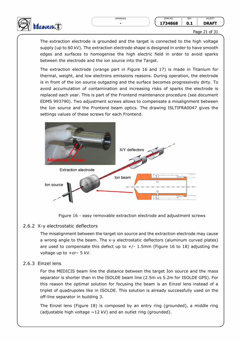
The extraction electrode is grounded and the target is connected to the high voltage
supply (up to 60 kV). The extraction electrode shape is designed in order to have smooth
edges and surfaces to homogenise the high electric field in order to avoid sparks
between the electrode and the ion source into the Target.
The extraction electrode (orange part in Figure 16 and 17) is made in Titanium for
thermal, weight, and low electrons emissions reasons. During operation, the electrode
is in front of the ion source outgazing and the surface becomes progressively dirty. To
avoid accumulation of contamination and increasing risks of sparks the electrode is
replaced each year. This is part of the Frontend maintenance procedure (see document
EDMS 993790). Two adjustment screws allows to compensate a misalignment between
the Ion source and the Frontend beam optics. The drawing ISLTIFRA0047 gives the
settings values of these screws for each Frontend.
Figure 16 - easy removable extraction electrode and adjustment screws
2.6.2 X-y electrostatic deflectors
The misalignment between the target ion source and the extraction electrode may cause
a wrong angle to the beam. The x-y electrostatic deflectors (aluminum curved plates)
are used to compensate this defect up to +/- 1.5mm (Figure 16 to 18) adjusting the
voltage up to +or– 5 kV.
2.6.3 Einzel lens
For the MEDICIS beam line the distance between the target Ion source and the mass
separator is shorter than in the ISOLDE beam line (2.5m vs 5.2m for ISOLDE GPS). For
this reason the optimal solution for focusing the beam is an Einzel lens instead of a
triplet of quadrupoles like in ISOLDE. This solution is already successfully used on the
off-line separator in building 3.
The Einzel lens (Figure 18) is composed by an entry ring (grounded), a middle ring
(adjustable high voltage ~12 kV) and an outlet ring (grounded).

REFERENCE EDMS NO. REV. VALIDITY
- 1734868 0.1 DRAFT
Page 22 of 31
Figure 17 - Enzel lens mounting
2.6.4 Beam optics optimisation
Simulations have been done to verify and optimize the beam optics parameters along
the beam line from the ion source up to the collection box. The system was simulated
using the software package SIMION. The simulations validated the position and the
geometry of the Einzel lens thus giving less pumping volume in the sector 1 by placing
the lens after the sector valve (Figure 18).
Figure 18 - geometry used for SIMION simulation
The mass separator consists of a double focusing dipole magnet with a 55 degrees
bending radius. The condition to achieve such a focusing in both axis requires the
formation of a parallel beam at the magnet entrance. The middle voltage in the middle
Einzel lens can be adjusted to ensure such a parallel beam.

REFERENCE EDMS NO. REV. VALIDITY
- 1734868 0.1 DRAFT
Page 23 of 31
Also, it is important to ensure that the beam will not touch the extraction electrode,
Einzel lens and magnet vacuum chamber to maximise transmission. The position of the
different optical elements was studied with SIMION.
Three beams of mass 99, 100 and 101 were launched from the ion source position. For
the case of an ion beam accelerated at 30 kV, with a 3 mm diameter (case of a surface
ioniser), an initial energy of 0.25 eV and 10 % energy spread we looked at the beam
profile at the focal plane, which would be the collection point.
Figure 19 - beam profile after mass separator for mass 99,100 and 101
The maximum resolving power that could be achieved under ideal conditions with this
magnet is R=1500. For the values mentioned above, R=400 which means that this
separator can resolve mass 100 from mass 99.75. From the plot above it can be seen
that neighbouring masses from central mass 100 are approximately 15 mm apart. This
beams will be directed to three different beamlines where the collection boxes will be
placed.
See more details in report EDMS 1585498.
REFERENCE EDMS NO. REV. VALIDITY
- 1734868 0.1 DRAFT
Page 24 of 31
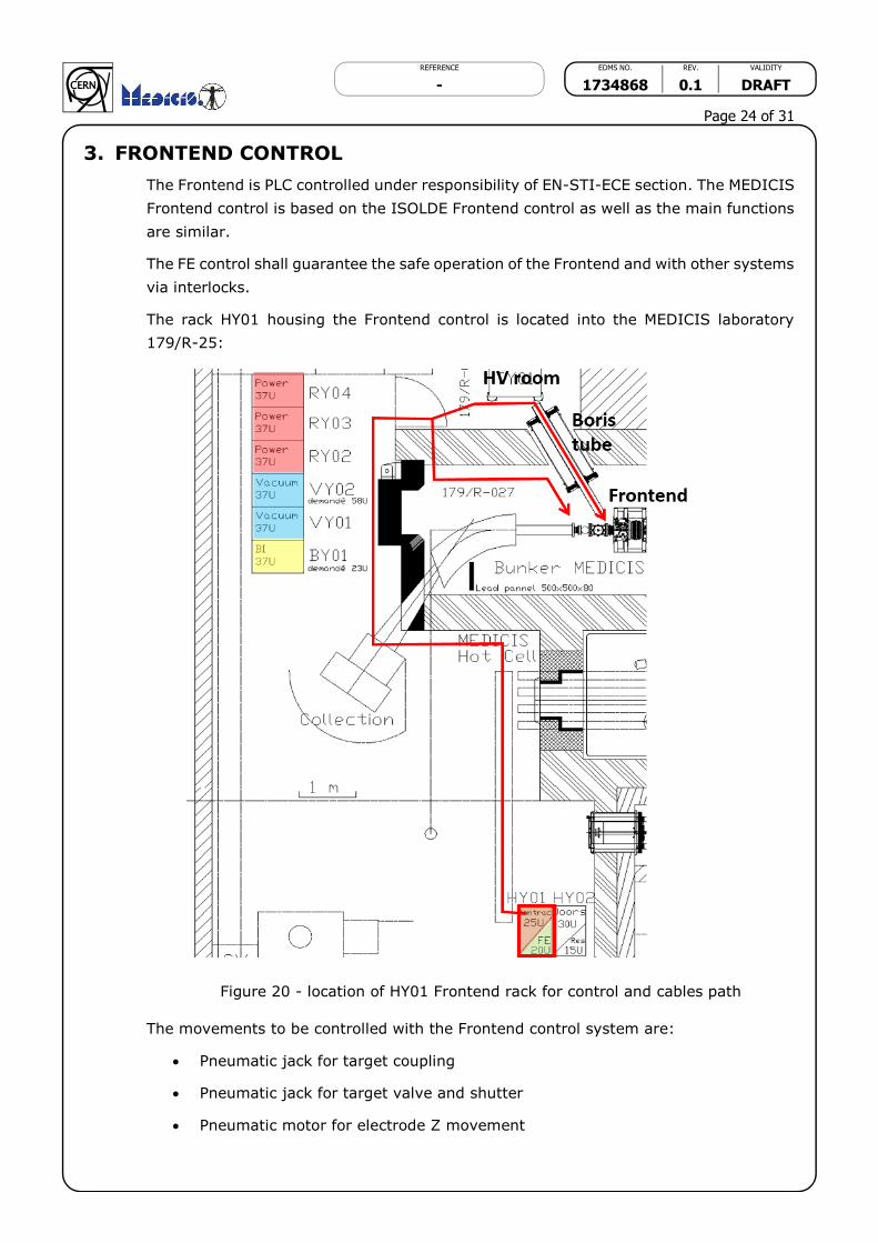
3. FRONTEND CONTROL
The Frontend is PLC controlled under responsibility of EN-STI-ECE section. The MEDICIS
Frontend control is based on the ISOLDE Frontend control as well as the main functions
are similar.
The FE control shall guarantee the safe operation of the Frontend and with other systems
via interlocks.
The rack HY01 housing the Frontend control is located into the MEDICIS laboratory
179/R-25:
Figure 20 - location of HY01 Frontend rack for control and cables path
The movements to be controlled with the Frontend control system are:
Pneumatic jack for target coupling
Pneumatic jack for target valve and shutter
Pneumatic motor for electrode Z movement
REFERENCE EDMS NO. REV. VALIDITY
- 1734868 0.1 DRAFT
Page 25 of 31
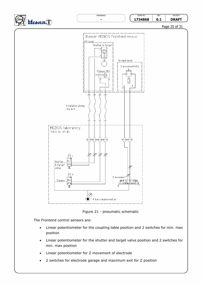
Figure 21 - pneumatic schematic
The Frontend control sensors are:
Linear potentiometer for the coupling table position and 2 switches for min. max
position
Linear potentiometer for the shutter and target valve position and 2 switches for
min. max position
Linear potentiometer for Z movement of electrode
2 switches for electrode garage and maximum exit for Z position
REFERENCE EDMS NO. REV. VALIDITY
- 1734868 0.1 DRAFT
Page 26 of 31
1 switch for the target presence detection on coupling table
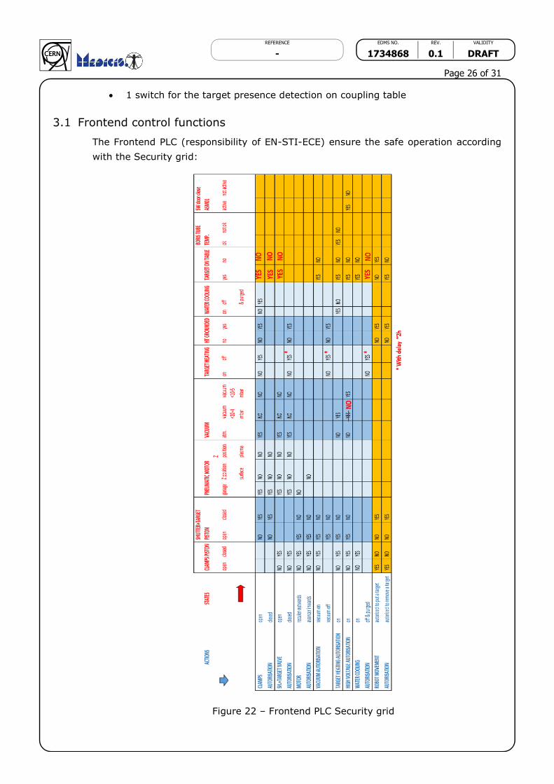
3.1 Frontend control functions
The Frontend PLC (responsibility of EN-STI-ECE) ensure the safe operation according
with the Security grid:
Figure 22 – Frontend PLC Security grid

REFERENCE EDMS NO. REV. VALIDITY
- 1734868 0.1 DRAFT
Page 27 of 31
3.2 Calibrations functions
The MEDICIS Frontend control shall allow (under expert mode) the manipulation of the
movements in order to do a calibration of the analogical value read on 3 the
potentiometers. This periodic calibration (once a year) prevent a deviation of calibration
due to mechanical wear or radiation damages.
3.3 Interlocks between Frontend control and other control systems
The Frontend control ensure a central role on the MEDICIS beam line operation and
interacts directly with other control systems. Figure 23 shows the interlocked systems
with the Frontend control (red darts):
Water cooling control
Vacuum control
Robot and doors control
High voltage control
Heating control
Other control systems are presents but are not directly interlocked with the Frontend
control.
Figure 23 – MEDICIS beam line interlock scheme

REFERENCE EDMS NO. REV. VALIDITY
- 1734868 0.1 DRAFT
Page 28 of 31
4. DELIVERABLES AND INTERFACES WITH OTHER WP
4.1 Deliverables
- Study of improvements and adaptations for the MEDICIS Frontend starting from a
ISOLDE Frontend
- Mechanical (redesign) and integration into the 3D CATIA model
- Design review (done 16.7.2016)
- Follow up the production and installation devices
- Mounting-dismounting and safety procedures
- Installation, alignment, cabling and commissioning
4.2 Interfaces with other work packages
- WP7 Bunker doors
- WP8 Separator
- WP10 Vacuum
- WP11 Target
- WP12 Robot
- WP15 General safety
- WP20 Drawings and 3D integration
- WP21 Power
- WP22 Beam instrumentation
- WP23 Water cooling
- No WP: Survey for alignment

REFERENCE EDMS NO. REV. VALIDITY
- 1734868 0.1 DRAFT
Page 29 of 31
5. SAFETY ASPECTS (to be completed by Ana Paula)
After the target itself, the Frontend is the most radiation and contamination exposed
device in the MEDICIS production chain. It has to be design according to the ALARA
principles for reliability, maintenance and replacement.

REFERENCE EDMS NO. REV. VALIDITY
- 1734868 0.1 DRAFT
Page 30 of 31
6. PLANNING
- 2016 January: start the mechanical study
- 2016 March: Edit control, power supply, vacuum, cooling specifications
- 2016 July: Proposal Design and Design review
- 2016 August: order components, reception
- 2016 November: Assembly
- 2016 December: Installation, alignment
- 2017 March: Cabling
- 2017 Mai: Commissioning (in reality October-November 2017)

REFERENCE EDMS NO. REV. VALIDITY
- 1734868 0.1 DRAFT
Page 31 of 31
7. BUDGET ESTIMATE and MANPOWER
As presented and accepted during MEDICIS Seminar, 2nd and 3rd March 2016:
7.1 Budget
Budget code 65406
60 kCHF (modifications FE9)
120 kCHF provisional for upgrade for Isolde
15 kCHF Boris Tube
TOTAL 195 kCHF (estimation)
FINAL 204 kCHF 21.11.2017 (including vacuum room building, installation of the
Boris Tube, hardware for control system and technician EN-MME for mechanical
mounting)
7.2 Manpower
0.6 for Mechanical Engineer
0.4 for Technician EN-MME
TOTAL 1 FTE