Embed Size (px)
Citation preview

M
MediaTek MT7681 Datasheet Version: 1.0 Release date: 3 January 2015
Specifications are subject to change without notice.
© 2015 MediaTek Inc. This document contains information that is proprietary to MediaTek Inc.
Unauthorized reproduction of this information in whole or in part is strictly prohibited.
MediaTek MT7681 Datasheet
Table of Contents
1 Introduction ................................................................................................................ 4
1.1 General Description ............................................................................................................................. 4 1.2 Features ................................................................................................................................................ 4 1.3 Applications .......................................................................................................................................... 5 1.4 Block Diagram ...................................................................................................................................... 5
2 Product Descriptions ................................................................................................... 6
2.1 Pin Layout ............................................................................................................................................. 6 2.2 Pin Descriptions ................................................................................................................................... 7 2.3 Strapping option................................................................................................................................... 8 2.4 Package Information ............................................................................................................................ 9 2.5 Ordering Information ......................................................................................................................... 11 2.6 Top Marking Information ................................................................................................................... 11
3 Electrical And Thermal Characteristics ........................................................................ 12
3.1 Maximum And Minimum Ratings ..................................................................................................... 12 3.2 Recommended Operating Ranges ...................................................................................................... 12 3.3 DC Characteristics ............................................................................................................................... 13 3.4 Thermal Characteristics ...................................................................................................................... 13 3.5 Current Consumption ......................................................................................................................... 14
4 Cautions ..................................................................................................................... 15
© 2015 MediaTek Inc. Page 2 of 15 This document contains information that is proprietary to MediaTek Inc.
Unauthorized reproduction or disclosure of this information in whole or in part is strictly prohibited. C

MediaTek MT7681 Datasheet
Lists of tables and figures
Table 1 MT7681 pin descriptions ................................................................................................................. 8
Table 2 Strapping option for the MT7681 .................................................................................................. 8
Table 3 MT7681 ordering information ....................................................................................................... 11
Table 4 Maximum and minimum ratings .................................................................................................. 12
Table 5 Recommended operating ranges ................................................................................................... 12
Table 6 DC characteristics ........................................................................................................................... 13
Table 7 Thermal characteristics .................................................................................................................. 13
Table 8 WLAN 2.4GHz current consumption............................................................................................ 14
Figure 1 MT7681 block diagram ...................................................................................................................5
Figure 2 Top view of MT7681 QFN pin-out. ............................................................................................... 6
Figure 3 MT7681 package outline drawing ................................................................................................. 9
Figure 4 MT7681 package outline drawing annotations ........................................................................... 10
Figure 5 Top marking on an MT7681 chip ................................................................................................. 11
© 2015 MediaTek Inc. Page 3 of 15 This document contains information that is proprietary to MediaTek Inc.
Unauthorized reproduction or disclosure of this information in whole or in part is strictly prohibited. C

MediaTek MT7681 Datasheet
1 Introduction
1.1 General Description
The MT7681 is a highly integrated Wi-Fi System on Chip (SoC), which supports IEEE802.11b/g/n
single stream, GPIO and PWM for intelligent control and UART/SPI interfaces for device
communication.
The MT7681 integrates a power amplifier, low noise amplifier and RF switch to reduce the module
size and simplify RF design in the final product. It also integrates a power management unit for a
single 3.3V power source.
A 32-bit RISC MCU is embedded in the MT7681 to run 802.11b/g/n drivers, wireless supplicant,
TCP/IP protocol stack and networking applications. It also helps provide Wi-Fi station and softAP
operation modes.
These features make the MT7681 a cost effective chipset for use in embedded devices that need to
enable Wi-Fi-based networking services with minimal design effort.
All these features are available in a compact 40 pin, 5mm x 5mm QFN package.
1.2 Features
The key features of the MT7681 are:
• Single stream IEEE 802.11b/g/n
• 32-bit RISC microprocessor host MCU
• Embedded IEEE 802.11b/g/n drivers, wireless supplicant and TCP/IP stack
• Highly integrated RF PA, LNA and RF switch
• Integrated high efficiency switching regulator for single 3.3V power source
• Security support for WPA personal (WPA-PSK), WPA2 personal (WPA2-PSK) and
WPA/WPA2 personal
• Operation in station or softAP modes
• Rich I/O interfaces: UART, SPI, PWM and GPIO
• All functions integrated in a compact 5mm x 5mm QFN40L package
© 2015 MediaTek Inc. Page 4 of 15 This document contains information that is proprietary to MediaTek Inc.
Unauthorized reproduction or disclosure of this information in whole or in part is strictly prohibited. C

MediaTek MT7681 Datasheet
1.3 Applications
The MT7681 is ideal for use in devices for these applications:
• Home automation
• Smart plugs
• Lighting
• Metering
• Remote control
• Consumer network devices
1.4 Block Diagram
Figure 1 shows the block diagram of the MT7681.
Figure 1 MT7681 block diagram
© 2015 MediaTek Inc. Page 5 of 15 This document contains information that is proprietary to MediaTek Inc.
Unauthorized reproduction or disclosure of this information in whole or in part is strictly prohibited. C

MediaTek MT7681 Datasheet
2 Product Descriptions
This section provides details of the MT7681, including:
• Pin layout
• Pin descriptions
• Strapping options
• Package information
• Ordering information
• Top markings
2.1 Pin Layout
Figure 2 shows a top view of the pin layout for the MT7681. These pins are described in detail in
section 2.2, “PIN Description”.
BG
_EXT
R
RF_
LDO
RF_
LDO
XTA
L_X
I
XTA
L_X
O
RF_
LDO
PLL_
LDO
VD
D33
VD
D12
GPI
O0
40 39 38 37 36 35 34 33 32 31 RF_LDO 1 30 GPIO1
RF_IN 2 29 GPIO2 RF_V33A 3 28 GPIO3 RF_OUTP 4 27 GPIO4 RF_OUTN 5
26 UART_TX
RF_V33A 6 25 UART_RX VDD33 7 24 LDO_RST_N
FLMISO 8 23 PMU_PHASE FLMOSI 9 22 PMU_V33
FLCS 10 21 PMU_COMP 11 12 13 14 15 16 17 18 19 20
FLCL
K
VD
D12
GN
D
GN
D
GN
D
GN
D
PMU
_12V
PMU
_V15
A
PMU
_V33
PMU
_FB
Figure 2 Top view of MT7681 QFN pin-out
© 2015 MediaTek Inc. Page 6 of 15 This document contains information that is proprietary to MediaTek Inc.
Unauthorized reproduction or disclosure of this information in whole or in part is strictly prohibited. C

MediaTek MT7681 Datasheet
2.2 Pin Descriptions
Table 1 provides descriptions of the pins on the MT7681.
QFN40 Pin Name Pin description Default PU/PD
I/O Supply domain
Reset and clocks 24 LDO_RST_N External system reset for active
low N/A Input VDD33
37 XTAL_XI Crystal or external clock input N/A Input
36 XTAL_XO Crystal output N/A Input
UART interface
25 UART_RX UART Rx N/A VDD33
26 UART_TX UART Tx N/A VDD33
FLASH interface
8 FLMISO External memory data input PD Input VDD33
9 FLMOSI External memory data output PD Output VDD33
10 FLCS External chip select PU Output VDD33
11 FLCLK External clock PU Output VDD33
Programmable I/O
30 GPIO0 Programmable input/output PD In/out VDD33
31 GPIO1 Programmable input/output PD In/out VDD33
29 GPIO2 Programmable input/output PD In/out VDD33
28 GPIO3 Programmable input/output PD In/out VDD33
27 GPIO4 Programmable input/output PD In/out VDD33
WIFI radio interface
40 BG_EXTR RF BG reference N/A
2 RF_IN RF auxiliary Rx input N/A
4 RF_OUTP RF port N/A
5 RF_OUTN RF port N/A
PMU
17 PMU_12V PMU 1.2V output N/A Output
18 PMU_V15A PMU 1.5V input N/A Input
19, 22 PMU_V33 PMU 3.3V power supply N/A Input
20 PMU_FB PMU control N/A
21 PMU_COMP PMU control N/A
23 PMU_PHASE PMU control N/A
Power supplies
7, 33 VDD33 Digital I/O power supply N/A Input
12, 32 VDD12 Digital core power supply N/A Input
© 2015 MediaTek Inc. Page 7 of 15 This document contains information that is proprietary to MediaTek Inc.
Unauthorized reproduction or disclosure of this information in whole or in part is strictly prohibited. C

MediaTek MT7681 Datasheet
QFN40 Pin Name Pin description Default PU/PD
I/O Supply domain
3, 6 RF_V33A RF 3.3V power supply N/A Input
1, 35, 38, 39
RF_LDO RF power supply N/A Input
34 PLL_LDO PLL power supply N/A Input
E-PAD DVSS Digital ground N/A
Table 1 MT7681 pin descriptions
2.3 Strapping option
Table 2 shows the strapping options for the MT7681.
QFN40 Pin Name Pin description Default PU/PD
8 FLMISO XTAL_20_SEL XTAL is 20MHz: Pull up XTAL is 40MHz: Pull down
PD
27 GPIO4 EXT_EE_SEL: Pull down PD
25 UART_RX CHIP_MODE[2]: Pull down PD
11 FLCLK CHIP_MODE[1]: Pull up PD
9 FLMOSI CHIP_MODE[0]: Pull down PU
Table 2 Strapping option for the MT7681
© 2015 MediaTek Inc. Page 8 of 15 This document contains information that is proprietary to MediaTek Inc.
Unauthorized reproduction or disclosure of this information in whole or in part is strictly prohibited. C

MediaTek MT7681 Datasheet
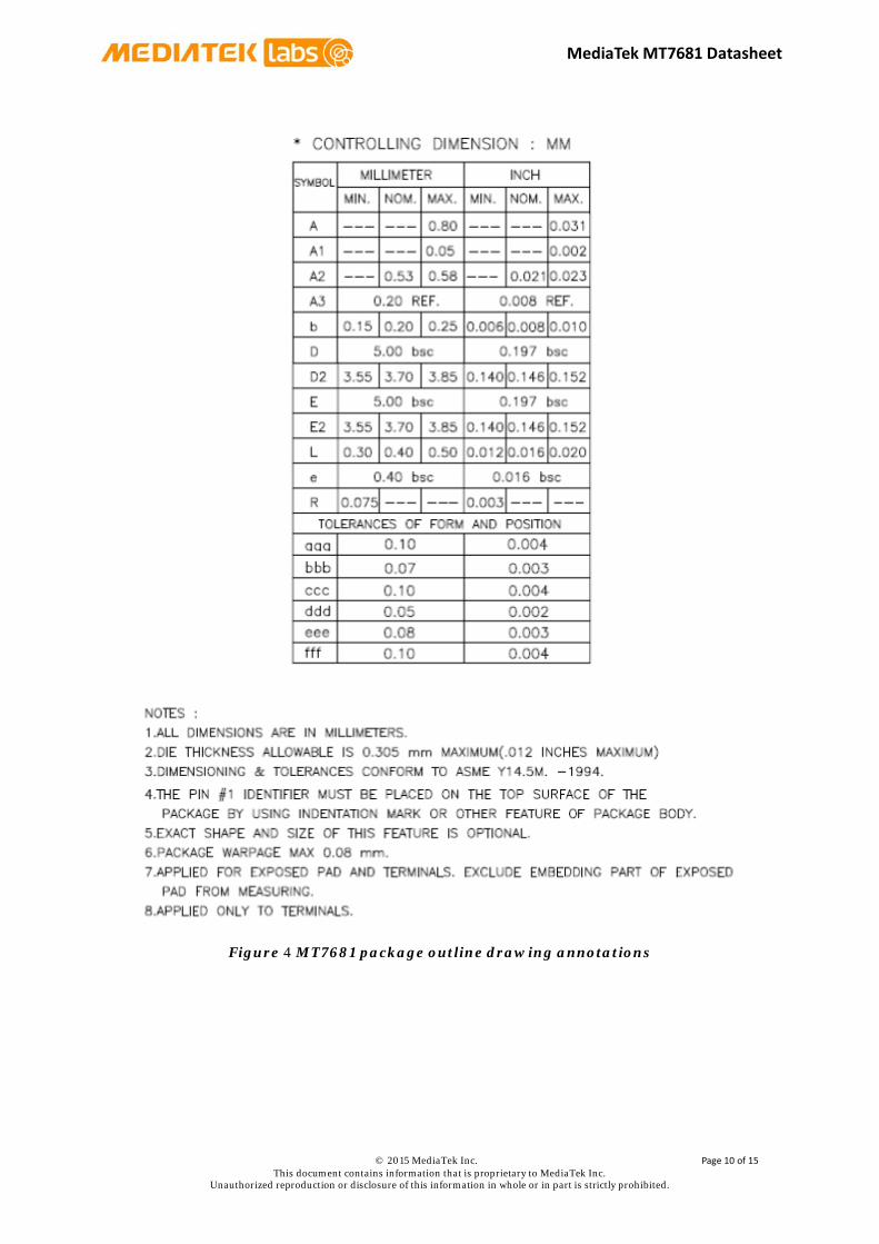
2.4 Package Information
This section provides details of the QNF packaging offered on the MT7681, including the package
drawings in Figure 3 and the drawing annotations in Figure 4.
Figure 3 MT7681 package outline drawing
© 2015 MediaTek Inc. Page 9 of 15 This document contains information that is proprietary to MediaTek Inc.
Unauthorized reproduction or disclosure of this information in whole or in part is strictly prohibited. C
MediaTek MT7681 Datasheet
Figure 4 MT7681 package outline drawing annotations
© 2015 MediaTek Inc. Page 10 of 15 This document contains information that is proprietary to MediaTek Inc.
Unauthorized reproduction or disclosure of this information in whole or in part is strictly prohibited. C

MediaTek MT7681 Datasheet
2.5 Ordering Information
Table 3 shows the ordering information for the MT7681.
Part number MT7681N
Package 5mm x 5mm x 0.8 mm 40-QFN
Operational temperature range -10 to 70°C
Table 3 MT7681 ordering information
2.6 Top Marking Information
Figure 5 shows the top marking displayed on a MT7681 chip.
Figure 5 Top marking on an MT7681 chip
© 2015 MediaTek Inc. Page 11 of 15 This document contains information that is proprietary to MediaTek Inc.
Unauthorized reproduction or disclosure of this information in whole or in part is strictly prohibited. C

MediaTek MT7681 Datasheet
3 Electrical And Thermal Characteristics
This section provides details of the electrical and thermal characteristics of the MT7681, including:
• Maximum and minimum ratings
• Recommended operating ranges
• DC characteristics
• Thermal characteristics
• Current consumption
3.1 Maximum And Minimum Ratings
Table 4 shows the maximum and minimum ratings for the MT7681.
Symbol Parameters Minimum rating
Maximum rating
Unit
VDD33 3.3V Supply Voltage -0.3 3.6 V
VDD12 1.2V Supply Voltage -0.3 1.5 V
VDD15 1.5V Supply Voltage -0.3 1.8 V
TSTG Storage Temperature -40 +125 °C
VESD ESD protection (HBM) 2000 V
Table 4 Maximum and minimum ratings
3.2 Recommended Operating Ranges
Table 5 shows the recommended operating ranges for the MT7681.
Symbol Rating Minimum Typical Maximum Unit VDD33 3.3V Supply Voltage 2.97 3.3 3.63 V
VDD12 1.2V Supply Voltage 1.14 1.2 1.26 V
VDD15 1.5V Supply Voltage 1.425 1.5 1.575 V
TAMBIENT Ambient Temperature -10 - 70 °C
Table 5 Recommended operating ranges
© 2015 MediaTek Inc. Page 12 of 15 This document contains information that is proprietary to MediaTek Inc.
Unauthorized reproduction or disclosure of this information in whole or in part is strictly prohibited. C
MediaTek MT7681 Datasheet
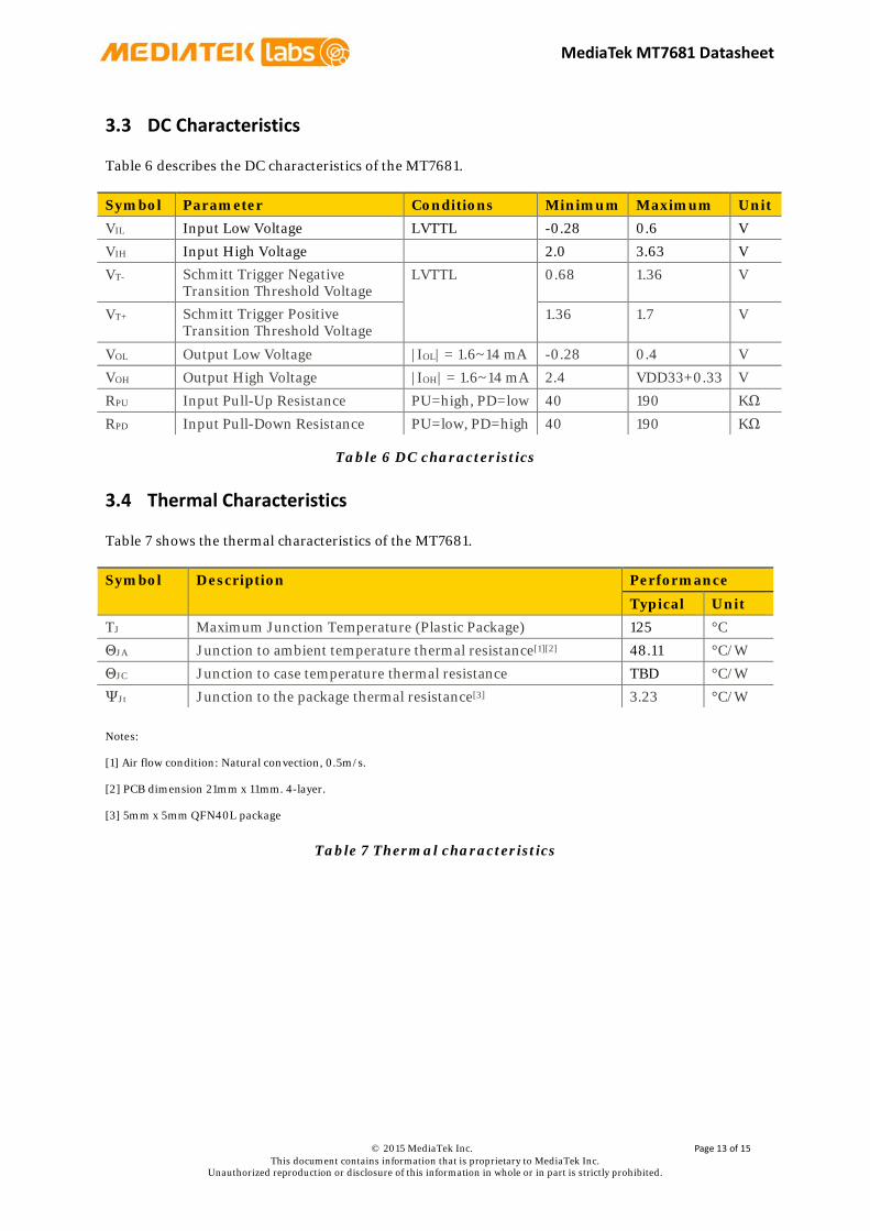
3.3 DC Characteristics
Table 6 describes the DC characteristics of the MT7681.
Symbol Parameter Conditions Minimum Maximum Unit VIL Input Low Voltage LVTTL -0.28 0.6 V
VIH Input High Voltage 2.0 3.63 V
VT- Schmitt Trigger Negative Transition Threshold Voltage
LVTTL 0.68 1.36 V
VT+ Schmitt Trigger Positive Transition Threshold Voltage
1.36 1.7 V
VOL Output Low Voltage |IOL| = 1.6~14 mA -0.28 0.4 V
VOH Output High Voltage |IOH| = 1.6~14 mA 2.4 VDD33+0.33 V
RPU Input Pull-Up Resistance PU=high, PD=low 40 190 KΩ
RPD Input Pull-Down Resistance PU=low, PD=high 40 190 KΩ
Table 6 DC characteristics
3.4 Thermal Characteristics
Table 7 shows the thermal characteristics of the MT7681.
Symbol Description Performance
Typical Unit TJ Maximum Junction Temperature (Plastic Package) 125 °C
ΘJA Junction to ambient temperature thermal resistance[1][2] 48.11 °C/W
ΘJC Junction to case temperature thermal resistance TBD °C/W
ΨJt Junction to the package thermal resistance[3] 3.23 °C/W
Notes:
[1] Air flow condition: Natural convection, 0.5m/s.
[2] PCB dimension 21mm x 11mm. 4-layer.
[3] 5mm x 5mm QFN40L package
Table 7 Thermal characteristics
© 2015 MediaTek Inc. Page 13 of 15 This document contains information that is proprietary to MediaTek Inc.
Unauthorized reproduction or disclosure of this information in whole or in part is strictly prohibited. C

MediaTek MT7681 Datasheet
3.5 Current Consumption
Table 8 shows the current consumption for the Wi-Fi features of the MT7681.
Description Performance
Typical Unit Sleep mode 1.1 mA
RX Active, HT40, MCS7 151 mA
RX Power saving, DTIM=1 15 mA
RX Listen 6 mA
TX HT40, MCS7 @15dBm 210 mA
TX CCK, 11Mbps @19dBm 242 mA
Note: All results measured at the antenna port with VDD33 at 3.3V
Table 8 WLAN 2.4GHz current consumption
© 2015 MediaTek Inc. Page 14 of 15 This document contains information that is proprietary to MediaTek Inc.
Unauthorized reproduction or disclosure of this information in whole or in part is strictly prohibited. C

MediaTek MT7681 Datasheet
4 Cautions
ESD CAUTION
MT7681 is an ESD (electrostatic discharge) sensitive device and may be damaged by ESD or spike
voltage. Although MT7681 has built-in ESD protection circuitry, please handle with care to avoid
permanent damage or performance degradation.
© 2015 MediaTek Inc. Page 15 of 15 This document contains information that is proprietary to MediaTek Inc.
Unauthorized reproduction or disclosure of this information in whole or in part is strictly prohibited. C


![[Enter Document title here] - MediaTek · MediaTek Company Profile ... UltraLow Power TriCluster CPU Subsystem with Adaptive Power Allocation for Optimal Mobile SoC Performance”,](https://img.dokumen.tips/doc/110x75/5ae0d3fc7f8b9a8f298eabc1/enter-document-title-here-mediatek-company-profile-ultralow-power-tricluster.jpg)