Embed Size (px)
Citation preview

Mechanisms for OAM on MPLS in large IP backbone networks
Masters Thesis, Information and Communication Technology
Agder University College
Faculty of Engineering and Science
By
Hallstein Lohne Johannes Vea
Grimstad, May 2002
Keywords: OAM, MPLS, BACKBONE, IP, ETHERNET, SNMP

MECHANISMS FOR OAM ON MPLS IN LARGE IP BACKBONE NETWORKS
Abstract
The telecom industry has an ongoing work on the Operation and Maintenance (OAM) mechanisms for the MultiProtocol Label Switching (MPLS) technology. We are expecting that this technology will be the future platform for sending Internet Protocol (IP) packets through the backbone networks. OAM functionalities that exist or are proposed for MPLS are: Reachability and failure detection, avoidance of congested routers, Simple Network Management Protocol (SNMP) features, fast rerouting functions, traffic engineering and ad-hoc mechanisms like Ping. Our work shows that through a comparison of OAM mechanisms of MPLS to IP, MPLS is superior on the failure detection, fast rerouting and the traffic engineering functionalities. A mechanism shows how one can use our new algorithm (a patent application is planned) to detect specific traffic behavior, making the MPLS backbone handle this traffic more logic. Different OAM mechanisms for MPLS give different levels of redundancy, which is often proportional to the OAM traffic load. We have found that the Connectivity Verification (CV) traffic load should be differentiated between the Label Switched Paths (LSPs) that need protection switching and those that do not. A short period between LSP CV packets is needed whilst still providing the best available bandwidth for working traffic A table shows different proposed fast rerouting and protection switching mechanisms, easing the operator’s choice of that mechanisms to use in large MPLS backbone networks. We propose the ITU-T LSP connectivity verification mechanism, fast rerouting and protection switching, and the use of MPLS MIB as recommended OAM mechanisms for large backbone networks.
AUC/ERICSSON © 2002 LOHNE, VEA i

MECHANISMS FOR OAM ON MPLS IN LARGE IP BACKBONE NETWORKS
Preface
This thesis is written for the Network Access department at Ericsson, Grimstad, and is a part of the Graduate degree (Siv. ing) in Information and Communication Technology (ICT) at Agder University College. This thesis is also a contribution to the research and development program The Mobile Student. The work on this thesis began in January 2002 by getting an overview of the main technologies involved and an understanding of the meaning of the term OAM. In the beginning of February 2002 we got in contact with Cisco in Norway, hoping to run a MPLS testbed at their test labs in Oslo. Many days were used for studying Cisco routers, MPLS protocols, packet monitoring and various software solutions for various measurements. When we were prepared to start testing in the start of April, Cisco did not get the equipment needed in time, and therefore the testbed was not feasible. Three supervisors have inspired us and been helpful in our work; they are Frode Trydal (Ericsson), Stein Bergsmark (Systems Manager, Ericsson) and Frithjof Fjeldstad (Agder University College). Discussion with and questions to persons attending various mailing lists have also given valuable information, and vice versa. We would like to thank the following people for providing us with answers to our questions posted at the various resources we have been using: Neil Harrison (British Telecom), David Allan (Nortel Network), Carlos Patriawan (Pluris.com), Carrie D. Harris (former Ericsson employee), Eng Wee, Mr. Ganesh (lntinfotech.com), Mark Gibs (onorchestream.com), Nirmit Kachrani (avaya.com), Mathew Lodge (cplane.com), Peter Morgan (AT&T), Mahesh Vsjetti (hns.com), Pall Ramanathan (arrisi.com), Robert Raszuk (Cisco), Roger Clark Williams (nordlink.com), Dr. Sidnie Feit (The Standish Group and a well-known author), Thomas D. Nadeau (Cisco) and Vic Nowoslawski (mac.com). Our thesis can be used to get an overview over MPLS and IP networks and provide an understanding of the OAM principles within an MPLS backbone network. We hope it will help Ericsson and others in finding the best solution to their future backbone networks. Grimstad, May 2002 Johannes Vea and Hallstein Lohne
AUC/ERICSSON © 2002 LOHNE, VEA ii

MECHANISMS FOR OAM ON MPLS IN LARGE IP BACKBONE NETWORKS
Contents
1 INTRODUCTION................................................................................................. 1 1.1 THESIS INTRODUCTION ...................................................................................1 1.2 THESIS DESCRIPTION.......................................................................................2 1.3 THESIS PROGRESS ...........................................................................................3 1.4 LITERATURE REVIEW ......................................................................................3 1.5 REPORT OUTLINE ............................................................................................4
2 AN OUTLINE OF IP AND MPLS TECHNOLOGIES..................................... 5 2.1 INTRODUCTION ...............................................................................................5 2.2 OAM AND BACKBONES IN GENERAL...............................................................5
2.2.1 What is OAM?............................................................................................5 2.2.2 A short introduction to backbones .............................................................8
2.3 FORWARDING MECHANISMS IN IP .................................................................11 2.3.1 An overview of the IP architecture ..........................................................11 2.3.2 Routing and forwarding...........................................................................12
2.4 THE MPLS ARCHITECTURE AND ITS FORWARDING MECHANISMS .................17 2.4.1 The MPLS architecture ............................................................................17 2.4.2 The control component ............................................................................23 2.4.3 The forwarding component ......................................................................26 2.4.4 An example of forwarding........................................................................27
3 A CLASSIFICATION OF OAM FUNCTIONALITIES................................. 29 3.1 INTRODUCTION .............................................................................................29 3.2 NETWORK MANAGEMENT .............................................................................29
3.2.1 Network Management Architectures........................................................29 3.2.2 SNMP .......................................................................................................30
3.3 OAM ON IP...................................................................................................34 3.3.1 Ping and ICMP ........................................................................................34 3.3.2 Traceroute................................................................................................36 3.3.3 IP MIBs ....................................................................................................37 3.3.4 New OAM functions in IPv6 ....................................................................37 3.3.5 ITU-T’s future OAM on IP.......................................................................38
3.4 OAM ON MPLS............................................................................................39 3.4.1 Current work overview ............................................................................39 3.4.2 LSP connectivity.......................................................................................39 3.4.3 MPLS ping ...............................................................................................47 3.4.4 RSVP node failure detection ....................................................................48 3.4.5 Protection Switching................................................................................48 3.4.6 Fast rerouting ..........................................................................................50 3.4.7 MPLS and traffic engineering..................................................................51
AUC/ERICSSON © 2002 LOHNE, VEA iii

MECHANISMS FOR OAM ON MPLS IN LARGE IP BACKBONE NETWORKS
3.4.8 MPLS SNMP MIBs ..................................................................................52 4 A COMPARATIVE ANALYSIS OF OAM MECHANISMS......................... 54
4.1 INTRODUCTION .............................................................................................54 4.2 FAILURE DETECTION .....................................................................................54 4.3 REACHABILITY FEATURES.............................................................................56 4.4 AVOIDANCE OF CONGESTED ROUTERS ..........................................................57 4.5 SNMP FEATURES..........................................................................................58 4.6 PING AND TRACEROUTE ................................................................................58 4.7 FAST REROUTING AND PROTECTION SWITCHING ...........................................59 4.8 TRAFFIC ENGINEERING..................................................................................61
5 OUR RECOMMENDED MECHANISMS AND NEW IDEAS ..................... 63 5.1 INTRODUCTION .............................................................................................63 5.2 RECOMMENDED OAM MECHANISMS FOR LARGE BACKBONE NETWORKS .....63 5.3 DIFFERENTIATION OF CONNECTIVITY VERIFICATION TRAFFIC .......................65 5.4 CLASSIFYING THE TRAFFIC............................................................................66
6 CONCLUSION.................................................................................................... 68 ABBREVIATIONS.................................................................................................... 70 TERMS ....................................................................................................................... 71 REFERENCES........................................................................................................... 74 APPENDIX A – CONFIGURING ROUTERS APPENDIX B – OPEN SHORTEST PATH FIRST (OSPF) APPENDIX C – AN MPLS SCENARIO APPENDIX D – CLASSIFYING THE TRAFFIC (RESTRICTED)
AUC/ERICSSON © 2002 LOHNE, VEA iv

MECHANISMS FOR OAM ON MPLS IN LARGE IP BACKBONE NETWORKS
1 Introduction
1.1 Thesis Introduction
The pioneer of telecommunication [1], Alexander Graham Bell, invented the telephone in 1876 and in the year 1884 the long distance circuit switched connection was ready for use. Many years later, in 1969, the first military packet switched data network [2] was constructed with few nodes that later increased in size and ended up as the Internet we know today. By the end of 1990, this data network technology became available for the general public. Ever since, it has been a research into new ways for the use of this technology. As it has been described by ITU-T [3], the data traffic is growing at more than ten times the rate of voice traffic. It is estimated that in the near future, data will account for 80% of all traffic carried by telecommunications networks. Therefore, with this rapid change, the past concept of telephone networks, which also carry data, will be replaced by the concept of data networks that also carry voice [3]. Other reasons can be that circuit switched network is less cost effective in terms of network utilization than IP-based network like Internet and new services, which need both voice and data transmission simultaneously. An evolution from simple document sharing and sending e-mail to using the Internet for real-time voice, video and entertainment is causing a convergence of the circuit switched telecommunication network and the IP-based network. Thus, the telecom industry has begun their task for using IP as the bearer of traffic. This has of course consequences for the best-effort services that Internet was intended for. Internet and other IP-based networks have not been able to guarantee low latency and reliable packet delivery at the low delay that is needed for services like real-time voice communication. There are possibilities to implement for example Integrated Services to accomplish this quality, but this gives no reliability when failure in the network occurs. The Internet has grown geographically, and the increase in number of hosts and traffic volume in its turn increases the operational efforts. With this in mind and the framework for the convergence explained above, a need for a more cost effective and reliable network technology has emerged. Cisco developed “tag switching”, which became a forerunner for the new technology, placed between layer 2 and 3 in the IP stack, and it was finally called Multiprotocol Label Switching (MPLS) [4]. MPLS has been a part of IETF since 1997 [4] and for ITU-T since second quarter of 2000, and these organizations will play key roles in the further developing of the MPLS
AUC/ERICSSON © 2002 LOHNE, VEA 1

MECHANISMS FOR OAM ON MPLS IN LARGE IP BACKBONE NETWORKS
technology [3]. A study of tier-one and tier-two in carriers in U.S by Infonetics Research shows that respectively 56% and 65% of them planned to implement MPLS in 2001 [4]. IETF, ITU-T and others develop OAM mechanisms for MPLS to secure failure detection and operation of the network. These OAM mechanisms are, in this thesis, to be compared to those in IP. Label Switch Path (LSP) connectivity [21] is used to verify that LSPs maintain connectivity and tells affected routers about failures. Another example of LSP connectivity functionalities is MPLS Ping [5]. The OAM packets traverses along the LSPs and a balance between OAM traffic and work traffic must be maintained. IP uses ICMP [18a] to advertise failures, but the MPLS architecture does not provide a similar mechanism. There exist proposals for different types of fast rerouting (read more at [35] [7]) and protection switching (read more at [32] [14]) for MPLS. These properties, which do not exist in IP, give the ability to switch quickly over to another LSP when failure on the working LSP has occurred. Traffic engineering (TE) on MPLS [31] gives network operators significant flexibility in controlling paths of traffic flows, that traverse across their networks. TE allows policies to be implemented that can optimize the performance of networks. Such possibilities are currently not available on IP.
1.2 Thesis description
This thesis shall evaluate OAM for MPLS networks. The principles with dedicated OAM cells will be compared to the use of other OAM mechanisms existing at the IP layer (e.g. SNMP), and MPLS OAM principles (IETF and ITU-T) shall be evaluated. The thesis shall propose mechanisms that can be recommended for large backbone networks. A study of ongoing activities within ITU-T and IETF is required. A testbed should, if feasible, be set up to perform necessary tests. A testbed with software routers (PCs) is recommended if this is implementable. If a testbed is to be used, a study of available software for simulating such routers must be performed. It will probably be necessary to write some additional software to insert the necessary OAM cells, as this probably doesn’t exist from any vendor yet. However, if the time shows that the use of a testbed is not implementable, the thesis will be performed theoretically.
AUC/ERICSSON © 2002 LOHNE, VEA 2

MECHANISMS FOR OAM ON MPLS IN LARGE IP BACKBONE NETWORKS
1.3 Thesis progress
During most of the time that we have been studying OAM on MPLS, we have been thinking of new properties for OAM on MPLS. We have come up with some new aspects on this field concerning OAM mechanisms. The main point of this thesis is to compare MPLS OAM cells to the existing at the IP layer, thus this thesis is not discussing what link layer protocols to use in a large backbone networks. Therefore, the link layer protocols ATM and Ethernet are not discussed in detail. Much work was laid down in finding suitable testbed architecture and applications for allocation of packet stream, and packet sniffing. Correspondence through mailing lists was also made to exchange ideas around the testbed. The testbed was to be carried out in the beginning of April, but due to complications at Cisco we had to postpone this testing. In the middle of May the complications were still not solved, and therefore we had to omit the testbed.
1.4 Literature review
Lately the telecommunication industry has been highly focused on how their leap towards using IP for telecommunication services. We expect that MPLS may be chosen for the bearer of IP in future large backbone networks, and that the OAM mechanisms of these backbones will be important. The current work at the Internet Engineering Task Force (IETF) in the draft Fast Rerouting [35] reveals an active working environment for OAM mechanisms on the MPLS platform. This fast rerouting protocol is originally intended for link layer errors, whilst the Protection Switching [32] at the International Telecommunication Union Telecommunication Standardization Sector (ITU-T) shows that rerouting can also be applied to the full LSP using various solutions. This is also a part of the OAM requirements that may be proposed for OAM functionality in MPLS networks [20] by the ITU-T. ITU-T has also been discussing various OAM mechanisms for MPLS [21] lately. The work on OAM standardisation is still in progress, and is highly prioritized in scientific e-mail based discussion groups, both at ITU-T and at the MPLS Resource Center [49]. We have also used several books in this thesis. One of them is Computer Networks: A System Approach [18], written by Larry L. Peterson and Bruce S. Davie. This book has increased our learning on IP in general. On the MPLS area, the book MPLS Technology and Applications [13], written by Bruce S. Davie and Yakow Tekhter, have provided us with a general introduction to MPLS.
AUC/ERICSSON © 2002 LOHNE, VEA 3
MECHANISMS FOR OAM ON MPLS IN LARGE IP BACKBONE NETWORKS
1.5 Report outline
This thesis should not be seen as a work reference or encyclopedia, but rather be seen in its entirety, where most pieces of information can be traced back to the starting chapter; giving valuable information as a whole. Chapter 2 gives the reader understanding in terms of the OAM, backbone, MPLS and IP technologies, and providing a basis for latter discussion. Chapter 3 describes OAM functions of these technologies and classifies them according to their functions, before we go into details of comparing the OAM mechanisms on MPLS to existing OAM mechanisms on IP in Chapter 4. In Chapter 5 we provide our recommended mechanisms and new ideas at the OAM level. Fortunately, one of these ideas may be patented, thus we had to move most of this information to Appendix D. The content of this idea is restricted, and may later be published to the general public. This information is of course still available to the censors. When it comes to references, it may be helpful for our readers to clarify how we have been using them in our text. Firstly, we have referred wherever possible. Even when we have altered the text, or provided sniplets from various sources, we still have given credit in form of a reference to the owners of the idea or the information. The references are a numeric number inside brackets like [“number”]. Sometimes, we have written a specific line that contains a number at the end before a period. This means that the above text is referred. When the content of a paragraph is referred from a single source, we give reference by providing a number in brackets after the period. Now we have given some information about the information and ideas provided by this thesis, now it’s your turn to take a dive into the world of OAM.
AUC/ERICSSON © 2002 LOHNE, VEA 4

MECHANISMS FOR OAM ON MPLS IN LARGE IP BACKBONE NETWORKS
2 An outline of IP and MPLS technologies
2.1 Introduction
This chapter contains the background information needed on the technologies affected in this thesis. It describes an outline needed to later understand how Operation and Maintenance (OAM) is solved within the different technologies. The various views of the term OAM, the reason why it is needed on a network and how the term will be used in this thesis is explained. To provide a basic understanding of large backbone networks, an outline to their structure and link protocols, is carried out. The IP architecture is more or less generally known, still a basic understanding of forwarding mechanisms and routing has been emphasized. This makes a deeper foundation of how routers forward packets through the IP network and their use of addresses. A more thorough presentation of the MPLS architecture is needed compared to IP, since this technology is new for most people. The control component communicates with other routers to build up paths between routers in the network. These paths are distinguished by a label. The forwarding component reads the small labels in the incoming MPLS packet header, and forwards the packet on its corresponding paths.
2.2 OAM and backbones in general
Not forgetting that this thesis mainly covers OAM on MPLS, it is included some aspects of the various elements that often are connected to OAM and MPLS. The term OAM and how different organizations define it is presented. While many views on the theme OAM exist, an OAM definition for this thesis is carried out. For the time being, MPLS is a technology that will mostly be used in backbone networks. Therefore, the structure of backbones and the different protocols, ATM and Ethernet, is described.
2.2.1 What is OAM?
There are several different definitions of what OAM is. Some understand this abbreviation to be Operation and Maintenance [17] and others understand it as Operation, Administration and Maintenance. While the meaning of the letters OAM
AUC/ERICSSON © 2002 LOHNE, VEA 5

MECHANISMS FOR OAM ON MPLS IN LARGE IP BACKBONE NETWORKS
is discussed, it is more important to get an overview of the different views on the term. Thomas D. Nadeau has expressed the variety of views. Specific networking technologies generally have one or more approaches for satisfying OAM requirements. Different approaches sometimes exist within the same networking technology too. According to on of the documents at ITU-T, OAM should take care of the need for ease of operation, the need for verifying network performance and the need to reduce operational costs. OAM mechanisms are especially important for networks that are required to deliver packets according to the requirements defined by the customers. These mechanisms should also try to take actions against defects in lower-layers that may not have taken appropriate actions. Typically, OAM is not only for preventing errors, it should also permit rapid diagnosis and localization of defects. This will in the end improve the availability. [20] The view of Carrie D. Harris is a little different. She says that if one has a node or link failure, one will need a report of services that are successfully carried out, and those that are not. The services that are not successfully carried out need to be placed into an alarm state. Smart systems with good integration will auto launch a network generated id for the corresponding error. Not only that, but these events are stored in a log for historical analysis. OAM is about alarms, performance thresholds, and fault isolation logic. According to Mr. Ganesh, OAM is a component that helps in Operation, Administration and Maintenance of a communication system, this way OAM can be thought of as a component that monitors the health of the system and gives us indications if something is wrong with the system. ITU-T’s OAM definition for the B-ISDN describes another view [17]:
• Performance monitoring produces maintenance information, allowing estimation of the network reliability.
• Defects and failures are detected by periodic checking. As a result, maintenance event information or various alarms will be produced.
• System protection by blocking or changeover to other entities, thus excluding the failing entity from operation.
• Defect information is given to management entities. Maintenance events are for example defects, failures and performance impairments [17]. Operation is not generally defined. But, at least to our knowledge, operation is a
AUC/ERICSSON © 2002 LOHNE, VEA 6

MECHANISMS FOR OAM ON MPLS IN LARGE IP BACKBONE NETWORKS
term that covers how one can operate a network. This might include terms like traffic engineering or ad hoc mechanisms like Ping. As one can learn from ITU-T, the various OAM needs are dependent on how the system works, and how one wish to operate and manage the system. One can discuss if administering a network should be added to the OAM definition. Administration functions may need logics that cannot be provided by the network itself, since these functions may be dependent on human interaction. However, if one operate and manage a system, one can also say that the system is administered. Thus the administrative part can still be included in the OAM definition. Strictly speaking, ITU-T has excluded Administration in their version of the Y.1710 [20] and Y.1711 [21] documents. One might ask why they still include the ‘A’ in OAM, but everybody have started using OAM and it has become a general term for those who are working with this. Since the definition of OAM may be vague, there is a need for a definition of OAM used in this thesis: Operation and Maintenance (OAM) is a term that covers how one gets an overview of the network performance and its traffic behaviour, the networks detection of errors and how they are handled, and the discovery of inconvenient configurations.
The mailman example Every time the mailman goes on his round trip, one can expect that the post will reach its destination. However, sometimes accidents might happen, or the mail might get delivered at a neighbors’ house. The incidents that might make the receiver worried of missing mail are endless. A network router that communicates on a network can be compared to a post-office that sends out mailmen with their mail. This mail can be compared to the network packets with their packet load. Of course these post-offices are, like routers, interconnected through a bigger network of post-offices. Consider this scenario if a postal system was a network with no OAM functions. The mailmen could be compared with network packets carrying their packet load following orders from their postal offices (compared to network routers) that send the mailmen on a mission along the different routes in their town (compared to network cables). These robot-like mailmen would still send out their letters and they would go home after a successful day. Everything would probably be fine. But if they encountered a traffic jam or an accident, they would still go home, because this was their program. Mail might also get delivered to wrong post-offices, and still the robot-mailmen would try delivering the mail. The mail-packets would eventually get lost if the programs of these robot-mailmen were not including any OAM functions.
AUC/ERICSSON © 2002 LOHNE, VEA 7

MECHANISMS FOR OAM ON MPLS IN LARGE IP BACKBONE NETWORKS
If we should transform this system to the network-semantics, this system would obviously need OAM functions; it needs a way to detect errors and it needs a way to monitor and manage the postal system. What we really would want is that the robot-mailmen would react as in real life. They would have a program for looking at mail-packets and report errors if they discover incorrectly delivered packets, or, if they encountered a traffic jam or an accident, did not get any packets at all delivered. However, today, the network packets themselves cannot have a program running on them, and the solution is to define the OAM functions in a router protocol. This protocol need to define how the packets are sent and it would need basic failure detection. Thus, the routers are the one that need error and reporting mechanisms within a network, and this is what today’s OAM is all about.
The non-technical side of OAM When most people think about network management, several things come to mind. These are likely to include routing protocols and tables, SNMP management stations, cables and so forth. Often, though, they fail to consider some of the more unnoticeable or non-technical components of network management. [12]
Router
Computer A Computer C
Computer B
Figure 1: Reachability in Networks
If Figure 1 is an environment of a small computer network, then both device A, B and C can reach each other using signals like Ping to check if the connection is okay. However, if computer A can reach both B and C, one can assume that B and C can reach each other. Of course, this depends on the link between B and C, or other issues. It is important to plan how to prevent that errors occur. However, if one do not understand how a network will react, or forget to consider the consequences of these activities to the entire network, one will find tasks like troubleshooting to be difficult. [12]
2.2.2 A short introduction to backbones
A large backbone can be defined as a collection of high-bandwidth links that has a number of routers throughout a larger geographical area, maybe as large as between
AUC/ERICSSON © 2002 LOHNE, VEA 8
MECHANISMS FOR OAM ON MPLS IN LARGE IP BACKBONE NETWORKS
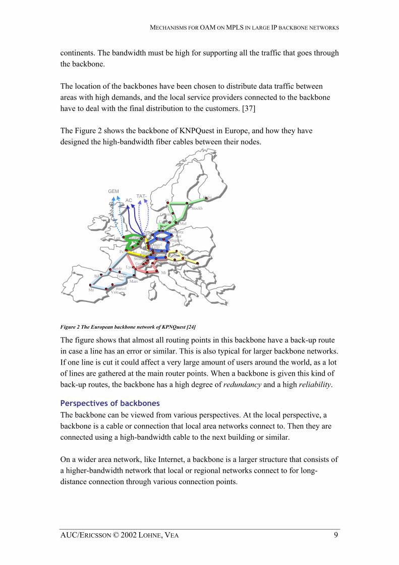
continents. The bandwidth must be high for supporting all the traffic that goes through the backbone. The location of the backbones have been chosen to distribute data traffic between areas with high demands, and the local service providers connected to the backbone have to deal with the final distribution to the customers. [37] The Figure 2 shows the backbone of KNPQuest in Europe, and how they have designed the high-bandwidth fiber cables between their nodes.
GEMTAT- Helsi
AC O
StockhGöten
Copenh Mal
Hamburg Bre
Figure 2 The European backbone network of KPNQuest [24]
The figure shows that almost all routing points in this backbone have a back-up route in case a line has an error or similar. This is also typical for larger backbone networks. If one line is cut it could affect a very large amount of users around the world, as a lot of lines are gathered at the main router points. When a backbone is given this kind of back-up routes, the backbone has a high degree of redundancy and a high reliability.
Perspectives of backbones The backbone can be viewed from various perspectives. At the local perspective, a backbone is a cable or connection that local area networks connect to. Then they are connected using a high-bandwidth cable to the next building or similar. On a wider area network, like Internet, a backbone is a larger structure that consists of a higher-bandwidth network that local or regional networks connect to for long-distance connection through various connection points.
Lyon 1 BStrasb a
Zur
MiTu
Gen B
DussColoelFrankLi
RoAntw
tterAmster
Brus
Lon
PaNurn Mun
Stutt
MannKarlsr hBo
MagdenBerHann
Leip
PraVie
SalzbBudaBorde
Bil TouloMars
BarcelMa Vale
AUC/ERICSSON © 2002 LOHNE, VEA 9

MECHANISMS FOR OAM ON MPLS IN LARGE IP BACKBONE NETWORKS
ATM versus Ethernet Large backbone networks often use asynchronous transfer mode (ATM) for their link layer. This is mainly because of its advantage over Ethernet when it comes to distances. Also, ATM provides high-speed data-transport together with a complex subset of traffic-management mechanisms [37]. When ATM switches first became available, there were significant advantages over existing solutions. In particular, switched networks have a big performance over shared-media networks: A single shared-media network has a fixed total bandwidth that must be shared among all hosts, whereas each host get its own dedicated link to the switch in a switched network. [18] Today, Ethernet is on its way to surpass ATM on backbone networks. By using fiber cabling for long distances Ethernet matches the distance of ATM networks, and the speed is increasing every year. The 10 Gigabit Ethernet is the latest Ethernet standard. Initially, network managers will use 10 Gigabit Ethernet to provide high-speed, local backbone interconnections between large-capacity switches. As the demand for bandwidth increases, 10 Gigabit Ethernet will be deployed throughout the entire network, and will include servers, backbone, and campus-wide connectivity. [50] Of course, there will always be a race among network equipment manufacturers to develop improved and faster MPLS routers for the Internet backbone. However, it is up to the future to show what kind of technology is preferred.
AUC/ERICSSON © 2002 LOHNE, VEA 10

MECHANISMS FOR OAM ON MPLS IN LARGE IP BACKBONE NETWORKS
2.3 Forwarding mechanisms in IP
2.3.1 An overview of the IP architecture
This subchapter begins with the Figure 3, describing how the layered Internet Protocol (IP) stack can be compared to the seven-layer Open Systems Interconnection Reference Model (OSI-RM). The involvement of Application layer is explained in
later. Figure 4
Figure 4 The IP architecture with the location of SNMP and ICMP shaded [45]
Application Application Layer 7
Presentation Layer 6
Session Layer 5
Transport TCP UDP Layer 4
Network Internet Protocol Layer 3
Ethernet, ATM … Data-Link Layer 2
Physical Layer 1
OSI model TCP/IP model
Figure 3: The OSI-RM model and compared to the TCP/IP model. The model is inspired by Figure 1.19 at [18b]
The Internet and ARPANET were around before the OSI architecture, and the experience gained from building them has had a major influence on the OSI reference model. [18b] As the IP packet header has been accepted during the end of the last century, many new services have been programmed for this platform. The Figure 4 provides a descriptive architecture of the packet switched IP. At bottom, IP and its semantics has, of course, never changed. By semantics we are thinking of the control information in a block. For more information, read the IPv4 packet header at [45].
Gopher | Kerb | Xwin | SNMP SMTP | Telnet | FTP | DNS | TFTP | Trace Route
Ping TCP UDP
ARP | RARP
ICMP IP
Ethernet | ATM | Token-Ring …
AUC/ERICSSON © 2002 LOHNE, VEA 11

MECHANISMS FOR OAM ON MPLS IN LARGE IP BACKBONE NETWORKS
As one can also see in , there exist applications that involves in a lower layer than the application layer. An example of these can be Ping. Thus, one can expand the application layer like one has shown in Figure 3.
Figure 4
2.3.2 Routing and forwarding
Forwarding of packets sent to various destinations is perhaps the most essential part of the Internet. Routing is the act of moving information across an internetwork from a source to a destination. On its way, unless one transfers on the local network, the packet almost always needs to go from one network to another. The process of getting the packets through the various networks is handled by routers.
Routers in general A router can be specified as one out of a spectrum of devices that may be used to interconnect different data networks [16]. Routers have improved in the latest years. They now have advanced features like traffic monitoring, which one can read using the SNMP protocol. The router determines the next network point in which to send a packet, and then forward it to its destination. The router must be connected to no less than two different networks and decides what destination to route a packet by inspecting the addresses of the packet. This is why a router is located at any gateway where one network is likely to meet another. To make contact with other routers, Internet Engineering Task Force (IETF) has helped standardized the Routing Information Protocol (RIP) for sharing routing information amongst routers. The RIP protocol requires the router to send its entire routing table to its neighbour router every 30 seconds. All routers can be defined to share this routing information, and they all updates within their Management Domain every 30 seconds. After RIP Version 1, this kind of information sharing among routers have improved. One can read more of these new protocols at IETF [23].
IP routing and forwarding Routing and forwarding have differences. Forwarding is the process of taking a packet from an interface and sending it out on the appropriate output, while routing is the process of building up the tables that allow the correct output for a packet to be determined. [18a] There exist two various methods of routing, direct routing and indirect routing. Indirect routing is when the hosts have to send data through a router to reach another network, while direct routing is when hosts send to another host on the same network. We also have static and dynamic routing. Static is done when the network operator manually configures the forwarding tables on the router. Dynamic routing is when the
AUC/ERICSSON © 2002 LOHNE, VEA 12
MECHANISMS FOR OAM ON MPLS IN LARGE IP BACKBONE NETWORKS
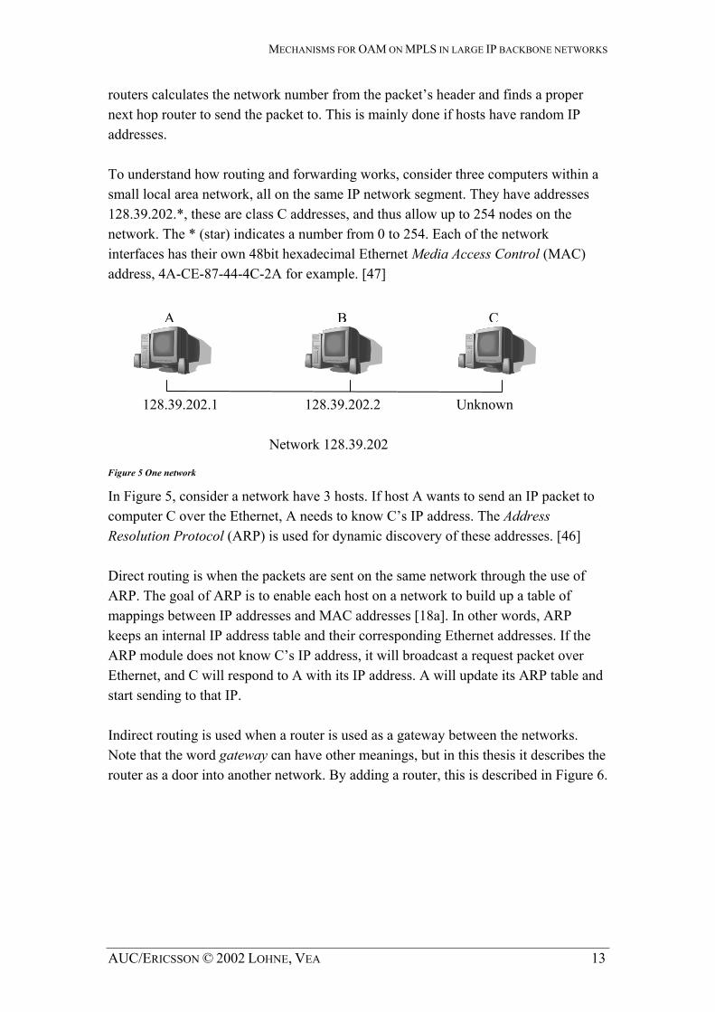
routers calculates the network number from the packet’s header and finds a proper next hop router to send the packet to. This is mainly done if hosts have random IP addresses. To understand how routing and forwarding works, consider three computers within a small local area network, all on the same IP network segment. They have addresses 128.39.202.*, these are class C addresses, and thus allow up to 254 nodes on the network. The * (star) indicates a number from 0 to 254. Each of the network interfaces has their own 48bit hexadecimal Ethernet Media Access Control (MAC) address, 4A-CE-87-44-4C-2A for example. [47]
A B C
128.39.202.1 128.39.202.2 Unknown
Network 128.39.202 Figure 5 One network
In Figure 5, consider a network have 3 hosts. If host A wants to send an IP packet to computer C over the Ethernet, A needs to know C’s IP address. The Address Resolution Protocol (ARP) is used for dynamic discovery of these addresses. [46] Direct routing is when the packets are sent on the same network through the use of ARP. The goal of ARP is to enable each host on a network to build up a table of mappings between IP addresses and MAC addresses [18a]. In other words, ARP keeps an internal IP address table and their corresponding Ethernet addresses. If the ARP module does not know C’s IP address, it will broadcast a request packet over Ethernet, and C will respond to A with its IP address. A will update its ARP table and start sending to that IP. Indirect routing is used when a router is used as a gateway between the networks. Note that the word gateway can have other meanings, but in this thesis it describes the router as a door into another network. By adding a router, this is described in Figure 6.
AUC/ERICSSON © 2002 LOHNE, VEA 13

MECHANISMS FOR OAM ON MPLS IN LARGE IP BACKBONE NETWORKS
A B
Figure 6 Two networks with one router
The Figure 6’s computer R forwards the packets between the networks. To do this, it needs two network interfaces, each listening on one of the networks. If A wants to send a packet to C, it first needs to send the packet to R, which in turn forwards the packet to C. This is done by making A use R’s Ethernet address that is obtained by using ARP, and, more importantly, C’s IP address. [47] Using manually configured routing table is called Static Routing, however this requires that the network interfaces on the network have statically configured IP addresses, and also requires them to not move outside their initiated network. If it is necessary to move a computer outside its initiated network, the routing table needs to be manually updated. An example of configuring routers by command-line utilities is explained in Appendix A. Dynamic routing uses special routing information protocols to automatically update the routing table with other routers in the network that share information. These protocols are grouped according to whether they are Interior Gateway Protocols (IGPs) or Exterior Gateway Protocols (EGP). Interior gateway protocols are used to distribute routing information inside a Management Domain. A Management Domain is a set of routers inside the domain administered by one authority. Examples of interior gateway protocols are Open Shortest Path First (OSPF) (see Appendix) and RIP. See RFC 1716 [11] for more information on IP router operations. [47] Static routing has some enormous advantages over dynamic routing. Chief among these advantages is predictability. Because the network operator computes the routing table in advance, the path a packet takes between two destinations is always known precisely, and can be controlled exactly. Additionally, because no dynamic routing protocol is needed, static routing doesn't impose any overhead on the routers or the
128.39.202.1 128.39.202.2
Network 128.39.202
NIC2: 128.39.202.3 C R (router) D NIC1: 128.39.203.10
128.39.203.1 128.39.203.2 Network 128.39.203
AUC/ERICSSON © 2002 LOHNE, VEA 14

MECHANISMS FOR OAM ON MPLS IN LARGE IP BACKBONE NETWORKS
network links. For a large network, the bandwidth devoted to routing updates can add up quickly. Finally, static routing is easy to configure on a small network. The network operator simply tells each router how to reach every network segment to which it is not directly attached. [12] Network mask By using logical bitwise-AND between the netmask and the IP address, the IP protocol can calculate if the target address should be sent to the local network, or through a gateway. When one set up an IP address for the network interface, one also has to specify the netmask. Normally, in Windows 2000, one add a default netmask of 255.255.255.0, which is the most common used netmask. We will not go into detail about how this is done, and how the network number and host number of the IP address is found.
Figure 7 Three networks interconnected Hn=Host Rn=Router [18a]
gure 7
The scenario in Figure 7 describes three networks interconnected using three different data link types, such as Ethernet (ETH), Fiber Distributed Data Interface (FDDI) and point-to-point (PPP). The routers forward the TCP packets from H1 to H8 as described in Figure 8. As one can see, the IP packets can be sent on various link layer formats and is therefore link-layer independent.
Figure 8 Describing what protocol layers used to connect H1 to H8 in Fi . Three routers equal 3 hops from H1 to H8. [18a]
H1 H8 H7
H3 H2
Network 1 (Ethernet) R3 Network 2 (Ethernet) R1
R2 Network 4
(point-to-point)
Network 3 (FDDI)
H4 H5 H6
H1 H8
TCP TCP R1 R2 R3
IP IP IP IP IP
ETH ETH FDDI FDDI PPP PPP ETH ETH
AUC/ERICSSON © 2002 LOHNE, VEA 15

MECHANISMS FOR OAM ON MPLS IN LARGE IP BACKBONE NETWORKS
Note that every IP datagram contains enough information to let the network forward the packet to their destination and this address lookup will take some time at every router. However, this makes no need for an advanced setup mechanism to tell the network what to do when the packet arrives. A host sends packets and the network makes its best effort to get them to their desired destination. The “best-effort” part means that if something goes wrong and the packet gets lost, the network does nothing – it made its best effort. Packets can come out of order, or they can be delivered many times, giving some work for protocols at the higher layers. Keeping routers as simple as possible was one of the main goals of IP. It has even been claimed that IP can run over a network that consists of two tin cans and a piece of string. [18a] Datagram Forwarding A datagram are sent from a source host to a destination host, possibly passing through several routers along the way. Any node, whether it is a host or a router, first tries to establish whether it is connected to the same physical network as the destination. By node we are thinking of a computer or hardware device that communicates on the network. This is done by the bitwise-AND between the netmask and the IP address. If the destination node is not connected to the local network, it needs to send the datagram to a router. In general, each node will have a choice of several routs, and so it needs to pick the best one, or at least one that has a reasonable chance of getting the datagram closer to its destination. The router finds the correct next hop by consulting its forwarding table. The forwarding table is conceptually a list of <NetworkNum, NextHop> pairs, as described in Figure 9. [18a]
NetworkNum NextHop
1 R3 2 R1
Figure 9 Example forwarding table for Router R2 in . Figure 7
In Figure 9 we have an example of how the router R2’s forwarding table would look like in our example scenario. The routers find the network number in the packet header, looks it up in a forwarding table and then send the packet to the next hop. By having reduced amount of information, one achieves scalability in the network. IP introduces a two-level hierarchy, with networks at the top level and nodes at the bottom level of the table. [18a] IPv6 extensions IPv6 has a much simpler header format then IPv4. Many of the unnecessary functionalities that are in the IPv4 header have been removed from the IPv6 header. This has resulted in a more effective router performance [18a]. The main difference,
AUC/ERICSSON © 2002 LOHNE, VEA 16

MECHANISMS FOR OAM ON MPLS IN LARGE IP BACKBONE NETWORKS
beyond the 16 bytes destination and source address, is that both the fragmentation and the option fields in the IPv4 header is moved out and placed in extension headers. There are also many other possible extension headers. When extension headers are present, they appear in a specific order [18a]. Another simplification is that the IPv6 header, in contrast to IPv4, always is of constant length. Both the “main” IPv6 header and the extension headers have the NextHeader field. This field contains an identifier of the type of extension header that comes next. The last extension header will be followed by a transport-layer header (e.g. TCP) and the NextHeader field will contain an identifier for that higher-layer protocol [18a]. There are six different extension headers and these are [34]:
• Hop-by-Hop Options • Routing • Fragment • Destination Options • Authentication • Encapsulating Security Payload
The most important header with respect to this thesis is the Routing header. The Routing header is used by an IPv6 source to list one or more intermediate nodes to be "visited" on the way to a packet's destination [34].
2.4 The MPLS architecture and its forwarding mechanisms
2.4.1 The MPLS architecture
MPLS is an abbreviation for Multi-Protocol Label Switching and the term multi-protocol has been chosen to stress that the method applies to all network layer protocols, not only IP. MPLS is about gluing connectionless IP to connection-oriented networks [37]. MPLS will also function virtually on any link layer protocol as well. The principle of MPLS is that all packets are assigned a label, and packets are forwarded along a Label Switched Path (LSP) where each router on the path performs forwarding decisions based solely on the contents of the label. The routers have forwarding tables indexed by the value of the incoming label. This is not the case for the IP forwarding table. This technology contributes a variety of new properties to the network architecture on lower layers. Examples are to guarantee a certain level of performance, to route around congested networks or to create IP tunnels for network-based virtual private networks. MPLS has the ability to create end-to-end circuits similar to a virtual circuit
AUC/ERICSSON © 2002 LOHNE, VEA 17

MECHANISMS FOR OAM ON MPLS IN LARGE IP BACKBONE NETWORKS
in ATM. MPLS also provides specific performance characteristics, such as traffic engineering across any type of transport medium. These opportunities reduce the need for overlay networks and layer two control mechanisms [37]. We have already a lot of knowledge about the link layer protocol Ethernet and less knowledge about other protocols like ATM and Frame Relay. It is not necessary to go thoroughly into all link layer protocols that MPLS is compatible with; therefore this thesis concentrates on Ethernet. To explain some various MPLS implementation on the link layer, also a description of MPLS on ATM is carried out. The network layer provides us with less choice. Currently there is only IP mentioned in the various documents surrounding MPLS. Even though MPLS is applied to all network layer protocols, this thesis describes this technology in respect to IP. The main reason is that most literature and specifications for time being almost merely deal with solutions concerning this protocol. The architecture of MPLS is specified in the IETF RFC 3031 [33]. MPLS is referred to as the “shim” layer. “Shim” refers to the fact that MPLS is between layer two and layer three in the OSI-RM model (see ) and MPLS makes them fit better [37].
Figure 10
Figure 10 The figure illustrate where the label switching protocol is in the OSI model and compared to the TCP/IP model
Application Application Application Layer 7
Presentation Layer 6
Session Layer 5
Transport Transport Transport Layer 4 Internet/networking Network Internet/networking Layer 3 Label switching
DataLink Network Access Layer 2 Network Access Physical Layer 1
OSI model TCP/IP model IP/MPLS model
The basic concept of label switching is very simple. Fore instance let us assume an e-mail message is sent from one user to another. In a best effort network like IP, the method to send this e-mail to its destination is similar to postal mail, assuming one does not use Zip codes and street addresses are unique. The destination address is examined and this address determines how the email is sent to its final destination [6]. Label switching is different. Instead of using the whole destination address to make the router decision, a label is associated with the packet. In the postal service analogy, a label value is placed on the envelope as a Zip code and is thereafter used in place of
AUC/ERICSSON © 2002 LOHNE, VEA 18

MECHANISMS FOR OAM ON MPLS IN LARGE IP BACKBONE NETWORKS
the postal address to route the mail to the recipient [37]. In computer networks, a label is placed in a packet header and the IP packet becomes the payload. The routers will now use the label instead of the IP-address to direct the traffic towards its destination (see Figure.)
Figure 11 : The MPLS functionality
MPLS network
Ingress LSR
Egress LSR Transit LSRs
Router Router
IP Payload IP Payload 6
IP load 3
IP Payload 9
IP Payload
A. Ingress LS eives an IP packet and uses, among other parameters, the IP address to assign
B.
is
B
C Pay
A R rec
a label for this packet and send it out on the LSP. If a suitable label is not available, the LSR has to ask the neighbor to assign a label which in its turn sends it back in the answer. The label in MPLS frame is used for lookups in the LSRs forwarding table to make forwarding decision. A label swap is performed.
C. The MPLS frame have arrived the egress LSR and the MPLS network border, the labelremoved and the IP packet is send towards the next router.
All the routers supporting MPLS is called Label Switch Routers (LSRs). The ingress
here are two alternative routing mechanisms for MPLS: Hop by hop routing and
ing
constructed according to this specified route.
LSR is where a packet enters the MPLS network. It adds an MPLS header to the IP packet and assigns a label. The egress LSR is where a packet leaves the network, andthe MPLS header is removed from the packet. Both ingress- and egress LSRs are edgenodes connecting the MPLS network to other networks. The transit LSR, also called an interior LSR, receives the packet between the MPLS edges and uses the MPLS header to make forwarding decisions. It will also perform label swapping [37]. Texplicit routing. In the hop by hop routing mechanism, the LSRs create the Label Switch Paths (LSPs) from ingress LSR to egress LSR by using their exchange information from peers. This exchanged information has been stored in the routtable at the LSR. In this way the LSRs construct a suitable path. Explicit routing is alittle different. The whole path or sub path for those LSRs to traverse from one edge to the other of the network is explicitly defined at the ingress and the LSP will be
AUC/ERICSSON © 2002 LOHNE, VEA 19
MECHANISMS FOR OAM ON MPLS IN LARGE IP BACKBONE NETWORKS
When the LSR performs packet forwarding, it
IP header Label 1 Data Label 2
strips off the existing label from the PLS packet at each hop and uses it as an index in its forwarding table. Once the
l stack. It is therefore possible to ave different LSPs at different levels in the label stack [37]. This functionality
ribed s
he routers R1 to R5 belong to two different LSPs. The numbers 1 and 2 are the label routers and R2, R3 and R4 are the interior routers.
e
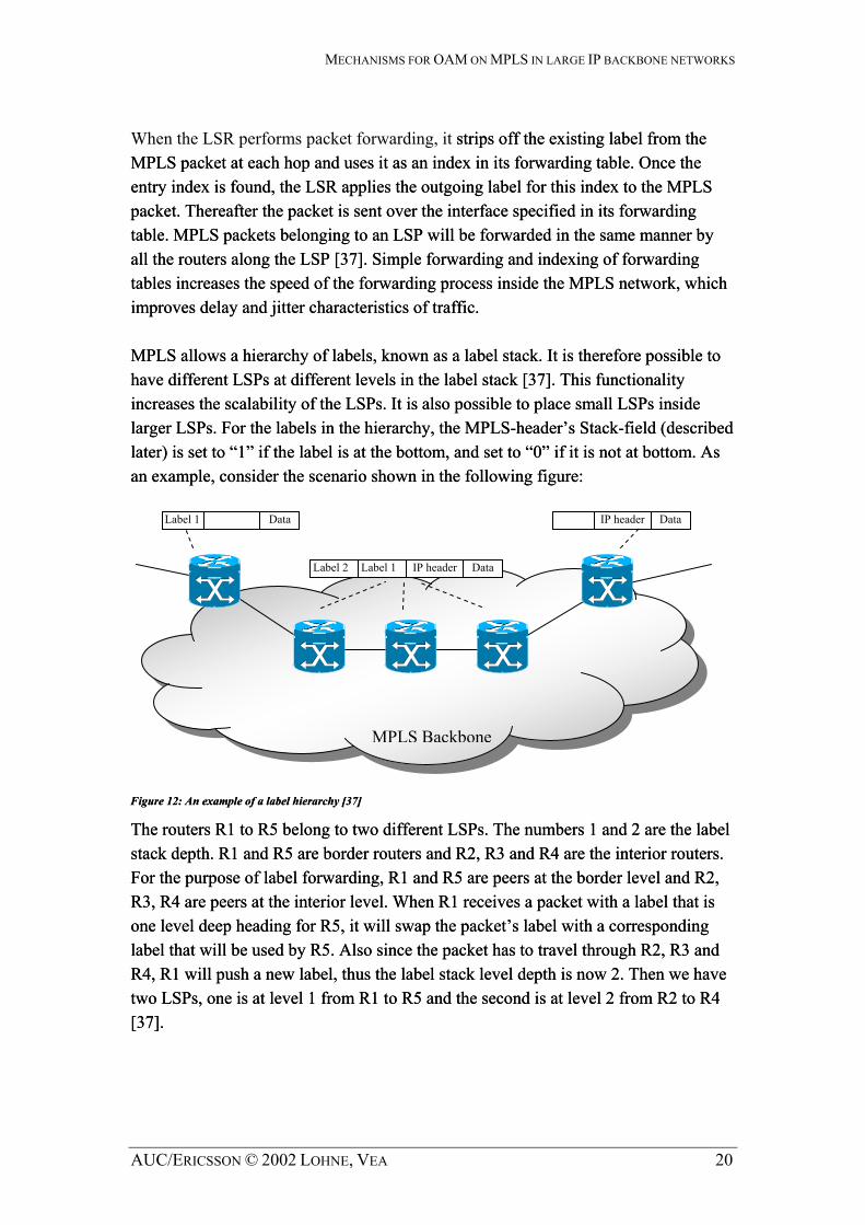
MMentry index is found, the LSR applies the outgoing label for this index to the MPLS packet. Thereafter the packet is sent over the interface specified in its forwarding table. MPLS packets belonging to an LSP will be forwarded in the same manner by all the routers along the LSP [37]. Simple forwarding and indexing of forwarding tables increases the speed of the forwarding process inside the MPLS network, whichimproves delay and jitter characteristics of traffic. MPLS allows a hierarchy of labels, known as a labe
entry index is found, the LSR applies the outgoing label for this index to the MPLS packet. Thereafter the packet is sent over the interface specified in its forwarding table. MPLS packets belonging to an LSP will be forwarded in the same manner by all the routers along the LSP [37]. Simple forwarding and indexing of forwarding tables increases the speed of the forwarding process inside the MPLS network, whichimproves delay and jitter characteristics of traffic. MPLS allows a hierarchy of labels, known as a labehhincreases the scalability of the LSPs. It is also possible to place small LSPs inside larger LSPs. For the labels in the hierarchy, the MPLS-header’s Stack-field (desclater) is set to “1” if the label is at the bottom, and set to “0” if it is not at bottom. Aan example, consider the scenario shown in the following figure:
increases the scalability of the LSPs. It is also possible to place small LSPs inside larger LSPs. For the labels in the hierarchy, the MPLS-header’s Stack-field (desclater) is set to “1” if the label is at the bottom, and set to “0” if it is not at bottom. Aan example, consider the scenario shown in the following figure:
IP header Label 1 Data Label 1 IP header Data
Figure 12: An example of a label hierarchy [37] Figure 12: An example of a label hierarchy [37]
MPLS Backbone
TTstack depth. R1 and R5 are borderstack depth. R1 and R5 are borderFor the purpose of label forwarding, R1 and R5 are peers at the border level and R2, R3, R4 are peers at the interior level. When R1 receives a packet with a label that is one level deep heading for R5, it will swap the packet’s label with a corresponding label that will be used by R5. Also since the packet has to travel through R2, R3 and R4, R1 will push a new label, thus the label stack level depth is now 2. Then we havtwo LSPs, one is at level 1 from R1 to R5 and the second is at level 2 from R2 to R4 [37].
For the purpose of label forwarding, R1 and R5 are peers at the border level and R2, R3, R4 are peers at the interior level. When R1 receives a packet with a label that is one level deep heading for R5, it will swap the packet’s label with a corresponding label that will be used by R5. Also since the packet has to travel through R2, R3 and R4, R1 will push a new label, thus the label stack level depth is now 2. Then we havtwo LSPs, one is at level 1 from R1 to R5 and the second is at level 2 from R2 to R4 [37].
AUC/ERICSSON © 2002 LOHNE, VEA 20

MECHANISMS FOR OAM ON MPLS IN LARGE IP BACKBONE NETWORKS
The label header for MPLS is located after the layer 2 header and before the layer 3 header. An example of Layer 2 and 3 headers are Ethernet and IP respectively. The location of the MPLS header and its format is illustrated in . Figure 13
Figure 13: The location of the MPLS header and the format of the MPLS header
LabelHeader
Layer 2Header
Layer 3Header
Layer 3 Payload
Label TTL EXP S
The MPLS “shim” label is 32 long and contains four fields. The MPLS header is illustrated in Figure 13 and contains the following fields [6a]:
• The label field of 20-bits carries the actual value of the MPLS label [37]. The values from 0 to 15 are reserved for special functions but only some of them are yet specified [22]:
- IPv4 Explicit NULL Label (value 0) - Router Alert Label (value 1) - IPv6 Explicit NULL Label (value 2) - Implicit NULL Label (value 3) - OAM Alert Label (value 14)[21]
• The 3-bits Exp/QoS experimental field can affect the queuing and discard algorithms applied to the packet as it is transmitted through the network [37].
• The 1-bit Stack (S) field indicates the bottom of the stack when label stacking is being used. S is zero when the label is not at the bottom of the label stack and one when if it is at the bottom of the stack [37].
• The 8-bits time-to-live (T) field is a copy of the TTL field in the IP header, and is decremented for each hop [37].
The “shim” method explained above is used for those layer 2 technologies that cannot accommodate labels in their header. These technologies are most link types except from Asynchronous transfer mode (ATM) and Frame Relay. For ATM and Frame Relay, the labels are carried in their link layer header. In ATM, the label can be carried in either virtual circuit identifier (VCI) or virtual path identifier (VPI) fields of the ATM header. Likewise, for Frame Relay, the label could be carried in Data Link Connection Identifiers (DLCI) field of the Frame Relay header [13]. We are increasing our understanding of how MPLS is implemented in ATM, but first a little introduction of ATM. ATM cells consist of a five bytes header and 48 bytes payload. In order to transport messages of greater sizes than 48 bytes that are handed
AUC/ERICSSON © 2002 LOHNE, VEA 21

MECHANISMS FOR OAM ON MPLS IN LARGE IP BACKBONE NETWORKS
down from layers like IP above, which is usually the case, ATM has to divide the messages into smaller parts. This is called fragmentation. The process of this fragmentation is handled by the ATM Adaptation Layer (AAL), which is placed between layer 2 and 3. The AAL header contains the information needed by the destination to reassemble the fragmented messages. An AAL5 Protocol data unit (PDU) will be divided into parts of 48 bytes and these 48 bytes including an ATM header form an ATM cell. When all the ATM cells that belong to a PDU arrive at the destination or the end of the ATM network, the PDU will be put together again [18].
AAL5 PDU
Label stack
AAL5 trailer Network layer packet
48 bytes 48 bytes 48 bytes
ATM headers carry top label in VCI/VPI field
Figure 14: Encapsulation of labeled packet on ATM link [13a].
Figure 14
When one whish to use encapsulation of MPLS labeled packets on ATM, the whole label stack will be carried in the AAL5 and the top level label will be carried in VCI/VPI filed in the ATM headers (see ). The reason for carrying labels in both AAL5 PDU and ATM header is mainly the arbitrary depth of label stacks. When the ATM cells reach the end of LSP, they will be reassembled. If there are more labels in the label stack, the AAL5 PDU will be fragmented again, and the label that is on top of the label stack will be put into the VCI/VPI field in the ATM headers. [18] So far we have been using the terms forwarding tables and routing tables about the tables containing forwarding and routing information respectively. The MPLS architecture describes other names for these tables; Label Forwarding Information Base (LFIB) and Label Information Base (LIB). The LIB contains all the label information that the LSR has learned from its neighbors (as said by Sidnie Feit, The Standish Group) next to it, in respect to the frame flow direction. The LFIB uses a subset of the labels contained in the LIB for actual packet forwarding [18b]. A further description of these two tables is performed in sub chapter 2.4.2 and 2.4.3.
AUC/ERICSSON © 2002 LOHNE, VEA 22

MECHANISMS FOR OAM ON MPLS IN LARGE IP BACKBONE NETWORKS
It is necessary to precisely specify which packets that may be mapped to each LSP. This is done by providing a Forwarding Equivalency Class (FEC) specification for each LSP. The FEC identifies the set of IP packets that may be mapped to that LSP. Each FEC is specified as a set of one or more FEC elements, where each element identifies a set of packets that may be mapped to the corresponding LSP. There are several FEC elements defined; the Address Prefix FEC element is an address prefix of any length from 0 to a full address. An IP address matches the Address Prefix only if that address begins with that prefix. Another FEC element is Host Address. This element is a full host address. Labels will be assigned to the FEC along the whole LSP [8]. The label is not merely depending of the FEC, it can also represent a combination of a packet’s FEC and the packets priority or class of service [33].
2.4.2 The control component
The control component is responsible for distributing routing information among LSRs and the procedures these routers use to convert this information into Label Forwarding Information Bases (LFIBs). These LFIBs will then be used by the forwarding components when forwarding MPLS frames. There is a great deal of similarity between the control component of the conventional routing architecture and the label switching control component. The MPLS control component includes all the functionalities from routing protocols used in conventional control components like OSPF, BGP and PIM. In this sense these control components forms a subset of the label switching control component. To fill the void procedures is needed by which an LSR can [13]:
• Create bindings between labels and FEC • Inform other LSRs of the binding it creates • Utilize both mechanisms above to construct and maintain the LFIBs
To perform binding between labels and FECs there are two methods. The first type of binding is referred to as local binding and occurs when the router creates a binding for the incoming label locally. The second type of binding, remote binding, is when the router receives label binding information from another LSR that corresponds to the label binding created by other routers. The label switching control component uses both local and remote binding to populate its LFIB with in-and-outgoing labels. To do this, there are two methods that are opposite of each other:
• Labels from the local binding become ingoing labels and labels from the remote binding are used as outgoing labels (downstream label binding).
• Labels from the remote binding become ingoing labels and labels from the local binding are used as outgoing labels (upstream label binding).
AUC/ERICSSON © 2002 LOHNE, VEA 23
MECHANISMS FOR OAM ON MPLS IN LARGE IP BACKBONE NETWORKS
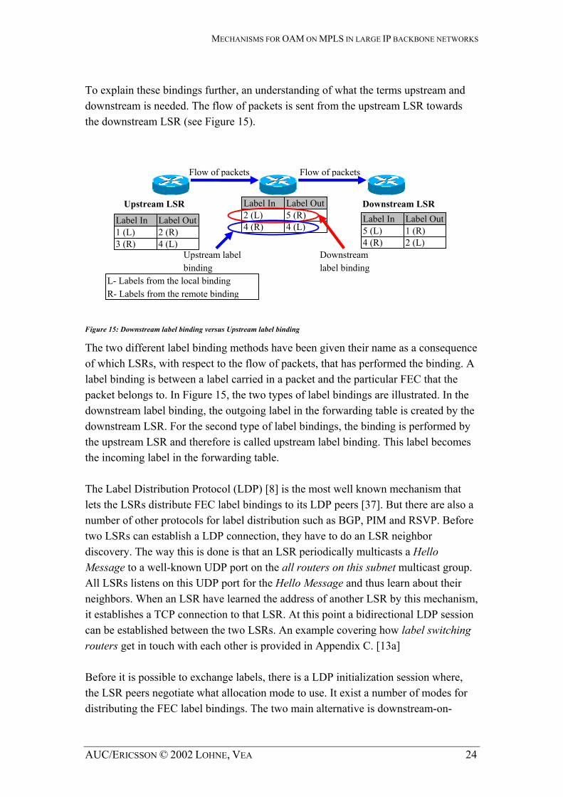
To explain these bindings further, an understanding of what the terms upstream and downstream is needed. The flow of packets is sent from the upstream LSR towards the downstream LSR (see Figure 15).
Flow of packets Flow of packets
Label In Label OutUpstream LSR Downstream LSR 2 (L) 5 (R) Label In Label Out Label In Label Out 4 (R) 4 (L) 5 (L) 1 (R) 1 (L) 2 (R)
4 (R) 2 (L) 3 (R) 4 (L) Upstream label binding
Downstream label binding
L- Labels from the local binding R- Labels from the remote binding
Figure 15: Downstream label binding versus Upstream label binding
The two different label binding methods have been given their name as a consequence of which LSRs, with respect to the flow of packets, that has performed the binding. A label binding is between a label carried in a packet and the particular FEC that the packet belongs to. In Figure 15, the two types of label bindings are illustrated. In the downstream label binding, the outgoing label in the forwarding table is created by the downstream LSR. For the second type of label bindings, the binding is performed by the upstream LSR and therefore is called upstream label binding. This label becomes the incoming label in the forwarding table. The Label Distribution Protocol (LDP) [8] is the most well known mechanism that lets the LSRs distribute FEC label bindings to its LDP peers [37]. But there are also a number of other protocols for label distribution such as BGP, PIM and RSVP. Before two LSRs can establish a LDP connection, they have to do an LSR neighbor discovery. The way this is done is that an LSR periodically multicasts a Hello Message to a well-known UDP port on the all routers on this subnet multicast group. All LSRs listens on this UDP port for the Hello Message and thus learn about their neighbors. When an LSR have learned the address of another LSR by this mechanism, it establishes a TCP connection to that LSR. At this point a bidirectional LDP session can be established between the two LSRs. An example covering how label switching routers get in touch with each other is provided in Appendix C. [13a] Before it is possible to exchange labels, there is a LDP initialization session where, the LSR peers negotiate what allocation mode to use. It exist a number of modes for distributing the FEC label bindings. The two main alternative is downstream-on-
AUC/ERICSSON © 2002 LOHNE, VEA 24

MECHANISMS FOR OAM ON MPLS IN LARGE IP BACKBONE NETWORKS
demand versus unsolicited downstream. Downstream-on-demand is when a LSR distribute a FEC label binding in response to an explicit request from another LSR while unsolicited downstream is distributing of label bindings without an explicit request from another LSR. Some of those other modes are ordered versus independent LSP control and liberal versus conservative label retention mode. [8] The Label Request Message is used by an upstream LSR, in consequence of a discovered new FEC, to explicitly request the downstream LSR to assign and advertise a label for this FEC. It is always the LSR downstream that must perform the binding for the link upstream. The FEC is transmitted to the downstream LSR in the FEC TLV in the Label Request Message. The receiving LSR should respond with a Label Mapping message with a label mapping for the requested label or with a Notification message indicating why it cannot satisfy the request [8]. The labels are locally significant only, meaning that the label is only useful and relevant on a single link, between adjacent LSRs [37]. The peer will in its turn send a Label Request message to its peer LSR if it does not already have a mapping in its LIB to which is the next hop. The next hop is a field in the LFIB and it describes the next router to forward labeled packets towards the egress LSR. These routers are specified according to the shortest path or least cost path algorithm. In this way the LFIB is populated. The establishment of a LSP explained so far is independent LSP control establishment. In the second method, ordered control LSP establishment, the ingress or egress LSR initiates the LSP setup. Label assignment is controlled in an orderly manner from the egress to the ingress of the LSP [18b]. That is, a Label Request Message must be send to each LSR along the path from its upstream LSR. No label bindings can be allocated before the message has reached the egress LSR. The Label Mapping message can now be send along the path in reversed direction towards the ingress LSR. For each LSR along the path the label binding is allocated and added to its LFIB. Sidnie Feit from The Standish Group has helped us to understand what the LIB is contributing to MPLS. The LIB contains all of the label information that an LSR has learned from its downstream neighbors both on demand and unsolicited. This information can be FEC Address Prefix, Neighbor LSR Identifier, Neighbor's IP address and FECs to label bindings. Since the LIB also contains unsolicited information, there will be entries that are not on the best path and consequently will not be used for forwarding. The LIB is not used to map incoming label to outgoing label. The methods explained so far are control components that enables establishment of forwarding states between adjacent LSRs solely based on information in routing
AUC/ERICSSON © 2002 LOHNE, VEA 25
MECHANISMS FOR OAM ON MPLS IN LARGE IP BACKBONE NETWORKS
tables or from a management system [27]. But these methods do not have the ability to establish label forwarding state on all the LSRs along an explicit route and the ability to reserve resources along the route. These and some other properties constitute the base of constraint based routing. There are two possible methods to achieve constraint-based LSPs: RSVP Traffic Engineering (RSVP-TE) and constraint-based routing LDP (CR-LDP). These signaling protocols enable MPLS to control the path of a packet by explicitly specifying the intermediate routers [15] and the route is calculated at one point at the edge of the network. The way things are done are fairly similar in both mechanisms, and only one of the methods will therefore be further described. CR-LDP [27] is using the Label Request Message in LDP to establish constraint-based routing. The LDP has been extended with new type-length-values (TLVs) in addition to the common LDP TLVs to accomplish this. TLV is an object description used in several protocols [49]. These new TLVs for LDP is called Constrained-based Routing TLVs (CR-TLV). When one wish to create constraint-based routing LSP (CR-LSP), the Label Request Message must carry at least the LSPID TLV and may carry one or more of the optional CR-TLVs in its Optional Parameters field. The LSPID TLV gives the CR-LSP an identity that can be used for modifying the LSP. When using CR-LDP it is possible to specify explicit routing and what resources to be allocated while LSP establishment.
2.4.3 The forwarding component
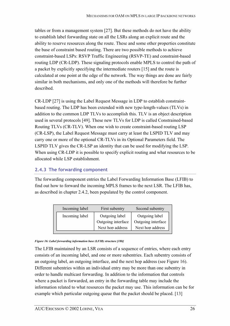
The forwarding component entries the Label Forwarding Information Base (LFIB) to find out how to forward the incoming MPLS frames to the next LSR. The LFIB has, as described in chapter 2.4.2, been populated by the control component.
Incoming label First subentry Second subentry
Outgoing label Outgoing interfaceNext hop address
Outgoing label Outgoing interface Next hop address
Incoming label
Figure 16: Label forwarding information base (LFIB) structure [18b]
The LFIB maintained by an LSR consists of a sequence of entries, where each entry consists of an incoming label, and one or more subentries. Each subentry consists of an outgoing label, an outgoing interface, and the next hop address (see Figure 16). Different subentries within an individual entry may be more than one subentry in order to handle multicast forwarding. In addition to the information that controls where a packet is forwarded, an entry in the forwarding table may include the information related to what resources the packet may use. This information can be for example which particular outgoing queue that the packet should be placed. [13]
AUC/ERICSSON © 2002 LOHNE, VEA 26

MECHANISMS FOR OAM ON MPLS IN LARGE IP BACKBONE NETWORKS
A LSR could maintain either a single forwarding table or a forwarding table for each of its interfaces. With the first alternative, handling of a packet is determined solely by the label carried in the packet. When the second alternative is used, handling of a packet is determined not just by the label carried in the packet but also by the interface that the packet arrives on. An LSR may use either the first or the second option, or a combination of both. [13] One important property of the forwarding algorithm used by label switching is that an LSR can obtain all the information needed to forward a packet as well as to decide what resources the packet may use in just one memory access. This is because [13]:
a) An entry in the forwarding table contains all the information needed to forward a packet as well as to decide what resources the packet may use.
b) The label carried in the packet provides an index to the entry in the forwarding table that should be used for forwarding the packet.
The ability to obtain both forwarding and resource reservation information in just one memory access makes label switching suitable as a technology for high forwarding performance. [13]
2.4.4 An example of forwarding
The routing example below illustrates the basic operation of MPLS in support of unicast routing. Using conventional IP routing protocols and LDP, the Label Switching Routers (LSRs) build up routing tables supplemented with labels called label information bases (LIBs). In , nodes A, B, C, and D are hosts not configured with MPLS. LSR1 is the ingress LSR, LSR2 is a transit LSR, and LSR3 is the egress LSR [37].
Figure 17
Figure 17: Label swapping and forwarding in MPLS [37].
A CPayload IP Payload IP 0 1
LSR1 in Figure 17 receives an IP datagram from user node A on interface 0, addressed for node C. LSR1 is the ingress LSR and performs the longest match lookup between the destination address in the datagram and the prefixes in its LIB.
Label IN
Label OUT
Next Hop Interface
- 3 LSR2 2 - 4 LSR2 2 ... ... ... ...
LFIB
Label IN
Label OUT
Next Hop Interface
3 7 LSR3 2 4 10 LSR3 2 ... ... ... ...
LFIB
Label IN
Label OUT
Next Hop Interface
7 - LSR3 2 10 - LSR3 2 ... ... ... ...
LFIB
0 12LSR1 LSR2 LSR3 Payload IP 3 Payload IP 7 0
B D1 2
AUC/ERICSSON © 2002 LOHNE, VEA 27

MECHANISMS FOR OAM ON MPLS IN LARGE IP BACKBONE NETWORKS
Other FEC to label binding procedures in its LIB is performed as well. In this way the initial label for the IP datagram is found and the label header encapsulate the IP datagram. The other forwarding properties, the next hop router and outgoing interface, is looked up in LSR1’s LFIB. The labeled IP datagram is forwarded with label 3 to the next hop LSR , which is LSR2, on output interface 2. When LSR2 receives the packet, only the label header is processed. It strips the label off and uses it as the lookup index in label IN column in its LFIB. The corresponding outgoing label for the incoming label 3 is “7” and replaces the incoming label with this outgoing label in the label header and forwards the labeled packet to LSR3 on interface 2. This is called label switching. The egress LSR processes the only label header as well and looks up the incoming label in its LFIB. LSR3 detects it as the egress of the LSP, when the next hop router is itself, and removes the label header from the incoming packet. The remaining of the packet, which is the same IP datagram packet as LSR1 received, is now forwarded on interface 2 to node C.
AUC/ERICSSON © 2002 LOHNE, VEA 28
MECHANISMS FOR OAM ON MPLS IN LARGE IP BACKBONE NETWORKS
3 A classification of OAM functionalities
3.1 Introduction
This chapter classifies the various OAM functionalities that exist or are proposed for IP and MPLS. Firstly, a description of a network management mechanism that can be used for manage both IP and MPLS networks. One can define network management as a generic solution for monitoring and checking the network for errors. The Simple Network Management Protocol (SNMP) has been created for this purpose. SNMP is used to retrieve information from routers be accessing their different Management Information Bases (MIBs) on nodes in the network. Secondly, a classifying of the different OAM mechanisms for IP and MPLS is described. IP does not have any suchlike mechanisms itself, but IP extensions like Internet Control Message Protocol (ICMP), Ping, Traceroute and MIBs are the main functionalities being used for this technology. In contrast MPLS has proposals for many different OAM mechanisms. The LSP connectivity verification mechanism detects different defects on LSPs and offer a number of different packet formats. MPLS ping, traceroute and RSVP node failure detection are other methods for failure detection. Protection switching and fast rerouting gives the network reliable packet delivery while MPLS traffic engineering and MPLS SNMP MIBs gives operational mechanisms.
3.2 Network management
3.2.1 Network Management Architectures
When it comes to Network Management, there are usually two primary elements: a manager and agents. The Manager has two purposes, collecting and visualizing information. It collects information from agents and uses various mechanisms for sorting and picking out relevant data. The agents are responsible of delivering information about the hardware or software. Generally, the agents are used for the purpose of tasks like monitoring traffic usage, number of clients connected and similar activities.
AUC/ERICSSON © 2002 LOHNE, VEA 29

MECHANISMS FOR OAM ON MPLS IN LARGE IP BACKBONE NETWORKS
NetworkDevice
Agent NMS
NetworkDevice
Agent
Network
NetworkDevice
Agent
Figure 18: Network Management Architecture
As one can see in Figure 18, the Network Management System (NMS) contacts the various routers and get the Management Information Bases (MIB) information from the router’s SNMP agents. The NMS can be some sort of network monitoring software running on a normal computer equipped with a network card. It exist a numerous different solutions for this purpose on the market, and they have all have various features.
3.2.2 SNMP
Since it was developed in 1998, the Simple Network Management Protocol (SNMP) has become a common way for monitoring the Internet Protocol (IP) network. SNMP is extensible, allowing vendors to easily add network management functions to their existing products. SNMP runs on top of UDP. The strategy implicit in the SNMP is that the monitoring of network states at any significant level of detail is accomplished primarily by polling for appropriate information for making the best possible management solution. A limited number of unsolicited messages (traps) guide the timing and focus of the polling. Limiting the number of unsolicited messages is consistent with the goal of simplicity and minimizing the amount of traffic generated by the network management function. [30] In other words, SNMP is a set of rules that makes many hardware devices, such as computers and routers, being able keep track of different statistics that measure important features, such as number of packets received on an interface. The different information SNMP retrieves is kept in each separate database, called Management Information Base (MIB). Other kinds of equipment have configuration information available through SNMP. The SNMP is an Application-layer protocol (see Figure 4) and is used almost exclusively in TCP/IP networks.
The MIB architecture It exist a large amount of different MIBs, giving many different aspects of the operation and performance of different devices. Using SNMP one can connect to
AUC/ERICSSON © 2002 LOHNE, VEA 30
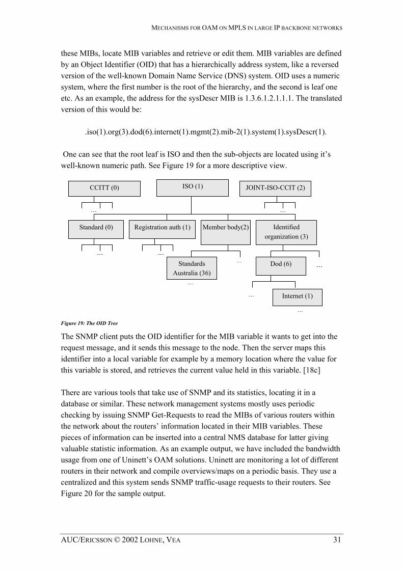
MECHANISMS FOR OAM ON MPLS IN LARGE IP BACKBONE NETWORKS
these MIBs, locate MIB variables and retrieve or edit them. MIB variables are defined versed
eric
ne can see that the root leaf is ISO and then the sub-objects are located using it’s
al variable for example by a memory location where the value for
hecking by issuing SNMP Get-Requests to read the MIBs of various routers within e ing
rent
a
by an Object Identifier (OID) that has a hierarchically address system, like a reversion of the well-known Domain Name Service (DNS) system. OID uses a numsystem, where the first number is the root of the hierarchy, and the second is leaf one etc. As an example, the address for the sysDescr MIB is 1.3.6.1.2.1.1.1. The translatedversion of this would be: .iso(1).org(3).dod(6).internet(1).mgmt(2).mib-2(1).system(1).sysDescr(1). Owell-known numeric path. See Figure 19 for a more descriptive view.
Figure 19: The OID Tree
The SNMP client puts the OID identifier for the MIB variable it wants to get into the request message, and it sends this message to the node. Then the server m ps this
Registration auth (1) Standard (0) Member body(2) Identified organization (3)
ardAustralia (36)
D
net (1) ......
...
...
... ...
......
ISO (1) CCITT (0) JOINT-ISO-CCIT (2)
s ...Stand od (6)
Inter
aidentifier into a locthis variable is stored, and retrieves the current value held in this variable. [18c] There are various tools that take use of SNMP and its statistics, locating it in a database or similar. These network management systems mostly uses periodic cthe network about the routers’ information located in their MIB variables. Thespieces of information can be inserted into a central NMS database for latter givvaluable statistic information. As an example output, we have included the bandwidthusage from one of Uninett’s OAM solutions. Uninett are monitoring a lot of differouters in their network and compile overviews/maps on a periodic basis. They use centralized and this system sends SNMP traffic-usage requests to their routers. See Figure 20 for the sample output.
AUC/ERICSSON © 2002 LOHNE, VEA 31

MECHANISMS FOR OAM ON MPLS IN LARGE IP BACKBONE NETWORKS
Figure 20: Oslo-Bergen daily traffic in kbit/s based on SNMP Get-Requests [11]
SNMP on network devices is today becoming almost a requiremthe single largest market for SNMP systems. A large portion of
ent. The Internet is SNMP systems will
e developed with the Internet as a target environment. Therefore, it may be expected ving force for SNMP. SNMP
or lient is correct or not. This password
is defined as a Read-only Community String. Usually, the default password is public all it default public community string. Many operators change the default
te. These traps might improve SNMP information,
bthat the Internet's needs and requirements will be the driover UDP/IP is specified as the "Internet Standard" protocol. Therefore, in order to operate in the Internet and be managed in that environment on a production basis, a device must support SNMP over UDP/IP. This situation will lead to SNMP over UDP/IP being the most common method of operating SNMP. Therefore, the widest degree of interoperability and widest acceptance of a commercial product will be attained by operating SNMP over UDP/IP. [39]
Security To access the SNMP agents, the SNMP Get-Request are used and will be accepteddenied according to if the password sent by the c
and some cRead-only Community String to keep information for the operators only. One can, on some devices, also define an IP filter for SNMP connection, thus improving security. There is also an SNMP Set-Request that can set and alter some MIB variables to a specific value. These Set-Requests are protected by the Write Community String that should be different than “public”. The SNMP also defines a SNMP Trap, which is an interrupt from a device to an SNMP console about the state of the device. Traps can indicate link-down/up and information surrounding power sta
AUC/ERICSSON © 2002 LOHNE, VEA 32
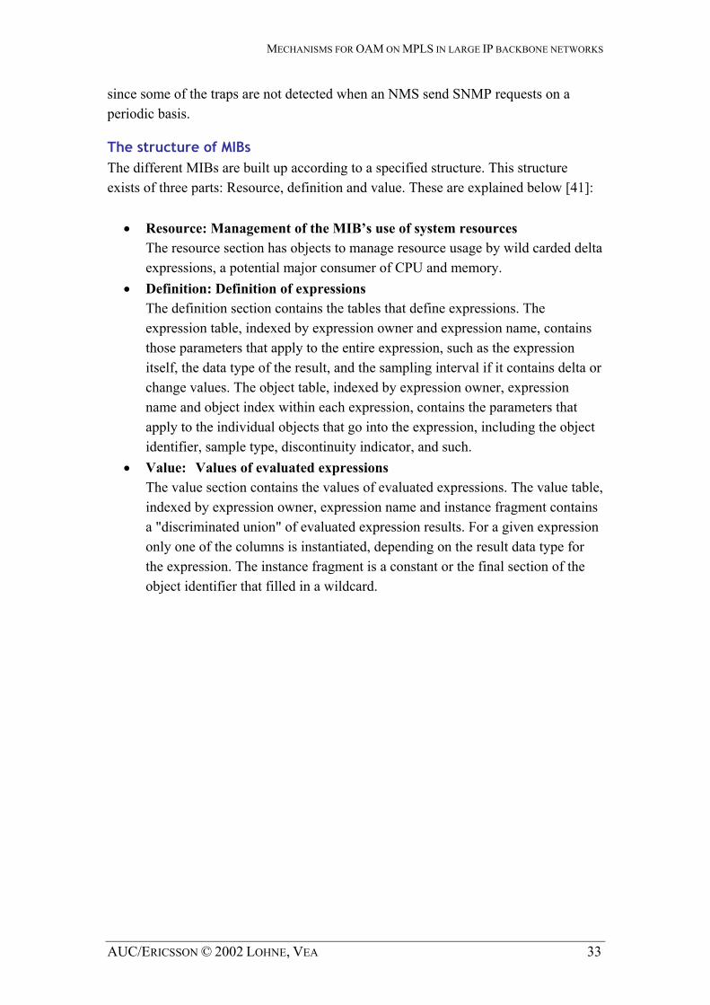
MECHANISMS FOR OAM ON MPLS IN LARGE IP BACKBONE NETWORKS
since some of the traps are not detected when an NMS send SNMP requests on a periodic basis.
The structure of MIBs The different MIBs are built up according to a specified structure. This structure exists of three parts: Resource, definition and value. These are explained below [41]:
expressions, a potential major consumer of CPU and memory.
ame, contains expression, such as the expression
delta or
•
ce fragment contains sion results. For a given expression
• Resource: Management of the MIB’s use of system resources
The resource section has objects to manage resource usage by wild carded delta
• Definition: Definition of expressions The definition section contains the tables that define expressions. The expression table, indexed by expression owner and expression nthose parameters that apply to the entireitself, the data type of the result, and the sampling interval if it containschange values. The object table, indexed by expression owner, expression name and object index within each expression, contains the parameters that apply to the individual objects that go into the expression, including the object identifier, sample type, discontinuity indicator, and such. Value: Values of evaluated expressions The value section contains the values of evaluated expressions. The value table,indexed by expression owner, expression name and instana "discriminated union" of evaluated expresonly one of the columns is instantiated, depending on the result data type for the expression. The instance fragment is a constant or the final section of the object identifier that filled in a wildcard.
AUC/ERICSSON © 2002 LOHNE, VEA 33

MECHANISMS FOR OAM ON MPLS IN LARGE IP BACKBONE NETWORKS
3.3 OAM on IP
To provide OAM on IP, a system operator can utilize different software management packages or advanced scripts for monitoring a network. These software solutions requests information from routers and switches, using ping, traceroute and SNMP. SNMP offers connectivity to various MIBs that contain information such as CPU-load, Traffic Load and other.
SNMPAgent
SNMPAgent
Ping OAM cell
SNMP MIB request
NMS
SNMPAgent
Figure 21 OAM on IP
The computer in Figure 21 collects information and stores the information on a periodic basis. This information gives valuable input for the OAM process for detecting failures or inconvenient behaviour. Regardless of the size of your network, whether a dozen nodes or thousands, one must establish a way to monitor the status of your network to see where it is working and where it is not. If one does not, you will be in the dark about what is going on, and you will constantly be fighting fires that could have been avoided. [12]
3.3.1 Ping and ICMP
The most common mechanism used for verifying whether routers and other nodes in the network is reachable or not is Ping. Ping measures the two-way delay between the source and the destination. One can also monitor the response time of the various systems using this small program. It takes use of the Internet Control Message Protocol (ICMP) fields to determine the various aspects of failure:
AUC/ERICSSON © 2002 LOHNE, VEA 34
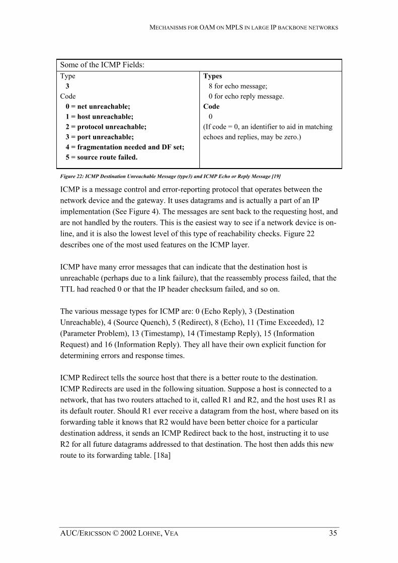
MECHANISMS FOR OAM ON MPLS IN LARGE IP BACKBONE NETWORKS
Some of the ICMP Fields: Type 3 Code 0 = net unreachable; 1 = host unreachable; 2 = protocol unreachable; 3 = port unreachable; 4 = fragmentation needed and DF set; 5 = source route failed.
Types 8 for echo message; 0 for echo reply message. Code 0 (If code = 0, an identifier to aid in matching echoes and replies, may be zero.)
Figure 22: ICMP Destination Unreachable Message (type3) and ICMP Echo or Reply Message [19]
Figure 22
ICMP is a message control and error-reporting protocol that operates between the network device and the gateway. It uses datagrams and is actually a part of an IP implementation (See Figure 4). The messages are sent back to the requesting host, and are not handled by the routers. This is the easiest way to see if a network device is on-line, and it is also the lowest level of this type of reachability checks. describes one of the most used features on the ICMP layer. ICMP have many error messages that can indicate that the destination host is unreachable (perhaps due to a link failure), that the reassembly process failed, that the TTL had reached 0 or that the IP header checksum failed, and so on. The various message types for ICMP are: 0 (Echo Reply), 3 (Destination Unreachable), 4 (Source Quench), 5 (Redirect), 8 (Echo), 11 (Time Exceeded), 12 (Parameter Problem), 13 (Timestamp), 14 (Timestamp Reply), 15 (Information Request) and 16 (Information Reply). They all have their own explicit function for determining errors and response times. ICMP Redirect tells the source host that there is a better route to the destination. ICMP Redirects are used in the following situation. Suppose a host is connected to a network, that has two routers attached to it, called R1 and R2, and the host uses R1 as its default router. Should R1 ever receive a datagram from the host, where based on its forwarding table it knows that R2 would have been better choice for a particular destination address, it sends an ICMP Redirect back to the host, instructing it to use R2 for all future datagrams addressed to that destination. The host then adds this new route to its forwarding table. [18a]
AUC/ERICSSON © 2002 LOHNE, VEA 35

MECHANISMS FOR OAM ON MPLS IN LARGE IP BACKBONE NETWORKS
Error reporting While IP is perfectly willing to drop datagrams when the going gets tough – for example, when a router does not know how to forward the datagram or when one fragment of a datagram fails to arrive at the destination – it does not fail silently. [18a] ICMP takes care of these errors, using one of the earlier mentioned error messages, and report them back to the sending host.
3.3.2 Traceroute
Sometimes one can not completely rely on Ping. If Ping fails, it does not tell which of multiple of routers between the two endpoints that is failing to deliver the packet. Traceroute fixes this problem by allowing to find out each intermediate router on the way from the host A to host B. It does this by causing each router along the path to send back an ICMP error message. IP packets contain Time-To-Live (TTL) value that each router decrements as it handles the packet. When this value drops to zero, the router discards the packet and sends an ICMP Time-to-live Exceeded message back to the sender. The first packet traceroute sends, are the TTL value of 1. The first router decrements this and sends back the ICMP error message, and traceroute has discovered the first hop router. It then sends a packet with a TTL value of 2, which the first router decrements and routes. But the second router decrements it to zero, which causes it to send an ICMP error message, and traceroute has learned the second hop. By continuing in this way, traceroute causes each router along the path to send an ICMP error message and identify itself. Ultimately, the TTL gets high enough for the packet to reach the destination host, and traceroute is done, or some maximum value (usually 30) is reached and traceroute ends the trace. [12] What really matters is that this function can be scriptable and used in a larger NMS. But Traceroute is mostly used manually by system operators to locate errors in their network. Note that Traceroute cannot completely be trusted for such tasks, since IP-packets may travel different routes each time one perform an IP traceroute. Sometimes, operators might use a pre-tested traceroute (by logging the output to a file), and compare it to the current traceroute to see how their network is rerouted and such. If they differ, rerouting might have occurred. One can also use the pre-tested traceroute to locate routers that are unreachable by using ping on each hop in the traceroute. A note about Time-To-Live (TTL) About Time-To-Live, its name reflects its historical meaning rather than the way it is commonly used today. The intent of the field is to catch packets that have been going around in routing loops and discard them, rather than let them consume resources indefinitely. Originally, TTL was set to a specific number of seconds that the packet
AUC/ERICSSON © 2002 LOHNE, VEA 36

MECHANISMS FOR OAM ON MPLS IN LARGE IP BACKBONE NETWORKS
would be allowed to live, and routers along the path would decrement this field until it reached 0. However, since it was rare for a packet to sit for as long as 1 second in a router, and routers did not all have access to a common clock, most routers just decremented the TTL by 1 as they forwarded the packet. Thus, it became more of a hop count than a timer, which is still a perfectly good way to catch packets that are stuck in routing loops. [18a]
3.3.3 IP MIBs
Since the nodes we need to keep track of are distributed, our only real option is to use the network to manage the network. This means we need a protocol that allows us to read, and possibly, write, various pieces of state information on different network nodes. [18c] MIB variables and such often just maintain hardware-specific information for the equipment in question. Manufacturers have a variety of information that can be monitored for their products. Examples of these variables are:
• sysUpTime, a system variable describing time since last reboot. • ifNumber, an interfaces variable, describing number of network interfaces.
It also exist IP-specific variables:
• ipDefaultTTL, an IP variable. Default Time-to-Live (TTL) field of the IP header of datagrams originated at this entity, whenever a TTL value is not supplied by the transport layer protocol.
• ipInReceives, an IP variable. The total number of input datagrams received from interfaces, including those received in error.
• ipOutNoRoutes, an IP variable. The number of IP datagrams discarded because no route could be found to transmit them to their destination. Note that this counter includes any packets counted in ipForwDatagrams that meet this ‘no-route’ criterion. This MIB includes any datagrams that a host cannot route because all of its default routers are down.
Variables adapted from [43] and [44]. These are just examples of variables in the jungle of MIBs.
3.3.4 New OAM functions in IPv6
In IPv6 it is support for address autoconfiguration of hosts and routers. There are two types of address autoconfiguration: Stateless and stateful. The stateless approach is used when a site is not particularly concerned with the exact addresses hosts use, as long as they are unique and properly routable. The stateful approach is used when a
AUC/ERICSSON © 2002 LOHNE, VEA 37

MECHANISMS FOR OAM ON MPLS IN LARGE IP BACKBONE NETWORKS
site requires tighter control over exact address assignments. Both stateful and stateless address autoconfiguration may be used simultaneously [34]. Stateless autoconfiguration requires no manual configuration of hosts, minimal (if any) configuration of routers, and no additional servers. The stateless mechanism allows a host to generate its own addresses using a combination of locally available information and information advertised by routers. Routers advertise prefixes that identify the subnet(s) associated with a link, while hosts generate an "interface identifier" that uniquely identifies an interface on a subnet. An address is formed by combining the two. But before the new local address can be used, the host must insure it selves against that other hosts are using or are going to use the same address [34]. In the stateful auto configuration model, hosts obtain interface addresses and/or configuration information and parameters from a server. Servers maintain a database that keeps track of which addresses have been assigned to which hosts [34].
3.3.5 ITU-T’s future OAM on IP
Study Group 13 is developing OAM network techniques that can be used to control and manage IP layer functions required in operations and maintenance, e.g. the Y.17xx Recommendations on MPLS. Study Group 15 is responsible for defining the implementation of these functions in IP network equipment, although much of this work is being done by IETF. Study Group 4 makes use of these OAM facilities to carry out management functions in the transport plane and control plane in concert with the TMN management capabilities. In an IP-based network environment, the distinction between control plane, signalling plane and management plane (TMN) is blurring. [3] ITU-T have said that they would look into how they can make support mechanisms for collection of information that can be used for charging users of the resources, specifically the end users of the services. They would also see into supporting mechanisms for collection of information that can be used for the Settlement between users of the resources, and support mechanisms for collection of performance and quality of service (QoS) information that can be used to support management of QoS and service level agreements (SLAs). [3] Also, ITU-T has said that OAM and protection switching issues of IP-based networks are to be considered. Requirements and issues are to be studied first. After requirements are decided, IP OAM functions have to be considered. [40] The question 4/13 [42] at ITU-T describes what eras ITU-T is planning to study:
• Define the traffic aspects of SLA for IP based services.
AUC/ERICSSON © 2002 LOHNE, VEA 38

MECHANISMS FOR OAM ON MPLS IN LARGE IP BACKBONE NETWORKS
• Specify the IP Transfer Capabilities and associated traffic contract derived from SLA statements. This should allow the support of real-time and non-real-time applications.
• Policy guidelines for defining traffic aspects in a SLA for IP based services. • Specify a traffic and congestion control framework for IP traffic. • Specify resource management and congestion control functions. • Specify traffic engineering methods and traffic engineering tools for IP.
More information on work on this area may appear by end of 2002. [40]
3.4 OAM on MPLS
3.4.1 Current work overview
The ongoing work on OAM on MPLS is in a state where there has been created some drafts but rather few recommendations and specifications. ITU-T has pre-published the recommendation Requirements for OAM functionality for MPLS networks that provides the motivations and requirements for user-plane OAM functionality in MPLS networks. The user-plane refers to the set of traffic forwarding components through which traffic flows [21]. The main motivation for this work have been the network operators expressed need for OAM functionality to ensure reliability and performance of MPLS LSPs. [20] IETF Network Working Group and Traffic Engineering Working Group have done a lot of research on OAM functionalities and most of their work on this area is still at draft state. Much of their work is dealing with how MPLS can give the best reliability when failures are detected. There is a need for minimize the packet loss when LSPs fails.
3.4.2 LSP connectivity
MPLS introduces new network architecture and therefore there will be new failure modes that are only relevant for the MPLS layer. Thus, layers above or below the MPLS layer cannot be used for MPLS-specific OAM needs. User-plane OAM tools are required to verify that LSPs maintain correct connectivity, and are thus able to deliver customer data to target destinations according to both, availability and QoS (Quality of Service) guarantees, given in SLAs (Service Level Agreements) [20]. Some of the requirements that must be supported by the MPLS OAM functions are [20]:
AUC/ERICSSON © 2002 LOHNE, VEA 39

MECHANISMS FOR OAM ON MPLS IN LARGE IP BACKBONE NETWORKS
• Both, on-demand and continuous connectivity verification of LSPs to confirm that defects do not exist on the target LSPs.
• A defect event in a given layer should not cause multiple alarm events to be raised simultaneously, or cause unnecessary corrective actions to be taken in the client-layers. The client layer is the layer above in the label hierarchy using current layer as a server layer.
• Capability to measure availability and QoS performance of a LSP. • At least the following MPLS user-plane defects must be detected [20]:
- Loss of LSP connectivity due to a server layer failure or a failure within the MPLS layer
- Swapped LSP trails
- Unintended LSP replication of one LSP’s traffic into another LSP’s traffic
- Unintended self-replication 16 values of the 20 bits large label field has been reserved in the label header for special functions, but not all have been specified yet. One of these functions that are proposed is the OAM Alert Label and has been given the numerical value of 14 [21].
LabelHeader Layer 2 Header OAM Payload (44 octets →)
Figure 23: MPLS OAM packet
There are different payloads depending on what OAM function the packet contains, but there is still a common structure for the payloads. At the beginning, each packet has an OAM Function Type field for specifying which OAM function there is in the payload. In each packet it is also the specific OAM function type data and at the end of the packet a Bit Interleaved Parity (BIP16) error detection mechanism. The BIP16 remainder is computed over all the fields of the OAM payload including the OAM Function Type and the BIP16 positions that are preset to zero. The payload must have at least 44 octets because this will facilitate ease of processing and to support minimum packet size required on layer 2 technologies. This is achieved by padding the specific OAM type data field with all “0”s when necessary [21]. OAM packets are differentiated from normal user-plane traffic by an increase of one in the label stack depth at a given LSP level at which they are inserted [21]. To ensure that the OAM packets have a Per Hop Behavior (PHB), ensuring the lowest drop probability, one has to code the EXP field a certain way. The EXP field should be set to all “0”s in the OAM Alert Labeled header and to whatever the 'minimum loss-
AUC/ERICSSON © 2002 LOHNE, VEA 40
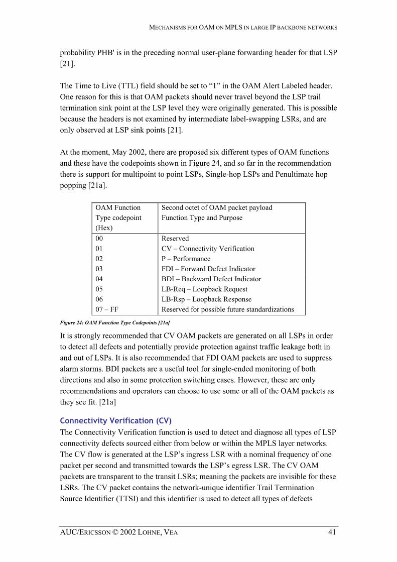
MECHANISMS FOR OAM ON MPLS IN LARGE IP BACKBONE NETWORKS
probability PHB' is in the preceding normal user-plane forwarding header for that LSP [21]. The Time to Live (TTL) field should be set to “1” in the OAM Alert Labeled header. One reason for this is that OAM packets should never travel beyond the LSP trail termination sink point at the LSP level they were originally generated. This is possible because the headers is not examined by intermediate label-swapping LSRs, and are only observed at LSP sink points [21]. At the moment, May 2002, there are proposed six different types of OAM functions and these have the codepoints shown in , and so far in the recommendation there is support for multipoint to point LSPs, Single-hop LSPs and Penultimate hop popping [21a].
Figure 24
Figure 24: OAM Function Type Codepoints [21a]
OAM Function Type codepoint (Hex)
Second octet of OAM packet payload Function Type and Purpose
00 Reserved 01 CV – Connectivity Verification 02 P – Performance 03 FDI – Forward Defect Indicator 04 BDI – Backward Defect Indicator 05 LB-Req – Loopback Request 06 LB-Rsp – Loopback Response 07 – FF Reserved for possible future standardizations
It is strongly recommended that CV OAM packets are generated on all LSPs in order to detect all defects and potentially provide protection against traffic leakage both in and out of LSPs. It is also recommended that FDI OAM packets are used to suppress alarm storms. BDI packets are a useful tool for single-ended monitoring of both directions and also in some protection switching cases. However, these are only recommendations and operators can choose to use some or all of the OAM packets as they see fit. [21a]
Connectivity Verification (CV) The Connectivity Verification function is used to detect and diagnose all types of LSP connectivity defects sourced either from below or within the MPLS layer networks. The CV flow is generated at the LSP’s ingress LSR with a nominal frequency of one packet per second and transmitted towards the LSP’s egress LSR. The CV OAM packets are transparent to the transit LSRs; meaning the packets are invisible for these LSRs. The CV packet contains the network-unique identifier Trail Termination Source Identifier (TTSI) and this identifier is used to detect all types of defects
AUC/ERICSSON © 2002 LOHNE, VEA 41

MECHANISMS FOR OAM ON MPLS IN LARGE IP BACKBONE NETWORKS
explained in chapter 0. This is obtained by egress LSR checking incoming CV packets per LSP. A LSP enters a defect state when one of the defects described in Figure 24 occurs [21]. The structure of the LSP TTSI is defined by using a 16 octet LSR ID IPv6 address followed by a 4 octet LSP Tunnel ID [21]. According to Neil Harrison and David Allan (both members of ITU-T Study Group 13 mailing list,) and what we can see, this LSP Tunnel ID is build up by the Local LSP_ID for CR-LDP tunnels [27] or the Tunnel ID for RSVP tunnels [26]. It could also be configured manually. The first 16 (two octets) most significant bits of the LSP Tunnel ID are currently padded with all “0”s to allow for any future increase in the Tunnel ID field [21]. For LSR that do not support IPv6 addressing, an IPv4 address can be used for the LSR ID using the format described in [29], IP Version 6 Addressing Architecture. [21]
Function Type Reserved LSP TTSI Padding BIP16
1 octet 3 octets 20 octets 18 octets 2 octets
Figure 25: CV payload structure
Forward Defect Indication (FDI) Forward Defect Indication is generated by an egress LSR detecting any defects. When the egress LSR detects a failure, it produces a FDI packet and traces it forward and upward through any nested LSP stack, also known as the label hierarchy (Figure 12). The FDI OAM packets are generated on a nominal one per second basis. [21a]. The FDI packets’ primary purpose is to suppress alarms in layer networks above the layer at which the defect occurs. To be able to send FDI packets upwards, it is important that the LSP sink point remembers any server-client LSP label mappings that were in existence prior to the failure. In this way, when higher level LSPs detects loss of CV flow caused by defects on lower level LSPs, we achieve correct identification of the source that actually had the defect. The higher layer clients may not be in the same management domain as the initial defect source. It includes fields to indicate the nature of the defect and its location [21].
When a FDI is to be passed from a server layer LSP to its client layer LSP(s), the Defect Location and Defect Type field should be copied from the server layer LSP FDI into the client layer LSP(s) FDI.
AUC/ERICSSON © 2002 LOHNE, VEA 42
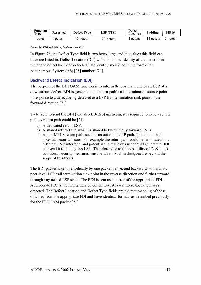
MECHANISMS FOR OAM ON MPLS IN LARGE IP BACKBONE NETWORKS
Function Type
Defect LocationReserved Defect Type LSP TTSI Padding BIP16
1 octet 1 octet 2 octets 4 octets 14 octets 2 octets 20 octets Figure 26: FDI and BDI payload structure [21]
In Figure 26, the Defect Type field is two bytes large and the values this field can have are listed in. Defect Location (DL) will contain the identity of the network in which the defect has been detected. The identity should be in the form of an Autonomous System (AS) [25] number. [21]
Backward Defect Indication (BDI) The purpose of the BDI OAM function is to inform the upstream end of an LSP of a downstream defect. BDI is generated at a return path’s trail termination source point in response to a defect being detected at a LSP trail termination sink point in the forward direction [21]. To be able to send the BDI (and also LB-Rsp) upstream, it is required to have a return path. A return path could be [21]:
a) A dedicated return LSP. b) A shared return LSP, which is shared between many forward LSPs. c) A non-MPLS return path, such as an out of band IP path. This option has
potential security issues. For example the return path could be terminated on a different LSR interface, and potentially a malicious user could generate a BDI and send it to the ingress LSR. Therefore, due to the possibility of DoS attack, additional security measures must be taken. Such techniques are beyond the scope of this thesis.
The BDI packet is sent periodically by one packet per second backwards towards its peer-level LSP trail termination sink point in the reverse direction and further upward through any nested LSP stack. The BDI is sent as a mirror of the appropriate FDI. Appropriate FDI is the FDI generated on the lowest layer where the failure was detected. The Defect Location and Defect Type fields are a direct mapping of those obtained from the appropriate FDI and have identical formats as described previously for the FDI OAM packet [21].
AUC/ERICSSON © 2002 LOHNE, VEA 43

MECHANISMS FOR OAM ON MPLS IN LARGE IP BACKBONE NETWORKS
Figure 27
Figure 27: How FDI and BDI are functioning when a failure is occurs.
gure 27
Figure 27: How FDI and BDI are functioning when a failure is occurs.
illustrates two things concerning LSP connectivity. The two gray areas in A) describe the way CV OAM packets are distributed from ingress to egress on different LSPs and label stack depths. A) describes how the CV packets are sent using level depth 1 and level depth 2 in the label hierarchy. B) describes what happens when a failure is detected, which LSR detects the failure and how it tells the others about the failure. The LSRs belongings to different LSPs and uses a label hierarchy to reach from ingress to egress LSR.
illustrates two things concerning LSP connectivity. The two gray areas in A) describe the way CV OAM packets are distributed from ingress to egress on different LSPs and label stack depths. A) describes how the CV packets are sent using level depth 1 and level depth 2 in the label hierarchy. B) describes what happens when a failure is detected, which LSR detects the failure and how it tells the others about the failure. The LSRs belongings to different LSPs and uses a label hierarchy to reach from ingress to egress LSR.
CV for LS1CV LS1 CV LS1 CV LS1
CV LS1 LS2 CV LS1 LS2
CV LS1 LS2 LS3 CV LS1 LS2 LS3
A) CV for LS2CV LS2 CV LS2 CV LS2 LS3 CV LS2 LS3
FDI LS1 LSR1 LSR7 LSR8 BDI FDI LS1 BDI
LSR2 LSR3 LSR6
B)
LSR4 LSR5
LS – Label Stack Depth CV – Connectivity Verification
Assume the name of the three LSPs in Figure 27 are A, B and C. The LSP A from LSR4 to LSR5 has label stack depth one; LSP B from LSR2 through LSR3 and over LSP A to LSR6 uses a label stack depth of two; and finely LSP C from LSR1 over LSP B through LSR7 to LSR8 uses a label stack depth of three.
Assume the name of the three LSPs in Figure 27 are A, B and C. The LSP A from LSR4 to LSR5 has label stack depth one; LSP B from LSR2 through LSR3 and over LSP A to LSR6 uses a label stack depth of two; and finely LSP C from LSR1 over LSP B through LSR7 to LSR8 uses a label stack depth of three. Consider a failure is detected between LSR2 and LSR 3. This will have consequences for both LSP B and LSP C. Both LSR6 and LSR 8 will detect that a failure has occurred even when the failure actually is at LSP B. To suppress alarms for LSP C at LSR8, LSR6 have to inform this router by sending FDI packets along the same path as the LSP C would be using before failure occurred. It is not only necessary to inform the downstream egress LSRs, LSR6 have to inform LSR 2, LSP B’s ingress
Consider a failure is detected between LSR2 and LSR 3. This will have consequences for both LSP B and LSP C. Both LSR6 and LSR 8 will detect that a failure has occurred even when the failure actually is at LSP B. To suppress alarms for LSP C at LSR8, LSR6 have to inform this router by sending FDI packets along the same path as the LSP C would be using before failure occurred. It is not only necessary to inform the downstream egress LSRs, LSR6 have to inform LSR 2, LSP B’s ingress
AUC/ERICSSON © 2002 LOHNE, VEA 44
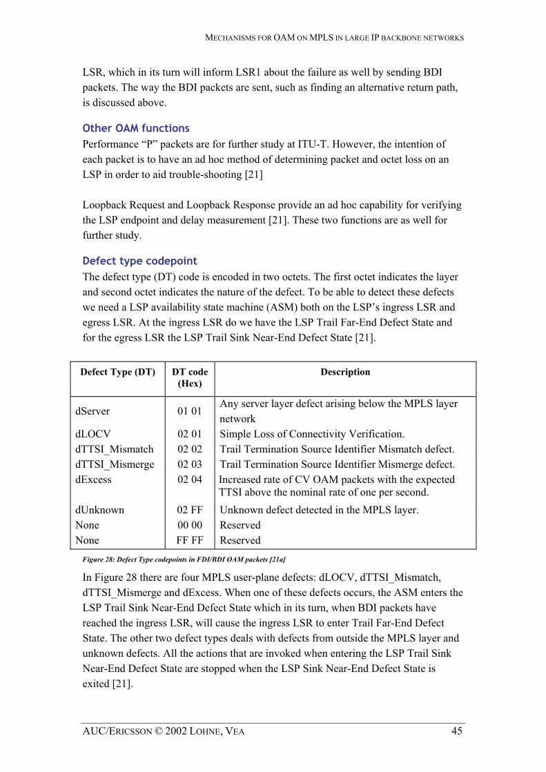
MECHANISMS FOR OAM ON MPLS IN LARGE IP BACKBONE NETWORKS
LSR, which in its turn will inform LSR1 about the failure as well by sending BDI packets. The way the BDI packets are sent, such as finding an alternative return path, is discussed above.
Other OAM functions Performance “P” packets are for further study at ITU-T. However, the intention of each packet is to have an ad hoc method of determining packet and octet loss on an LSP in order to aid trouble-shooting [21] Loopback Request and Loopback Response provide an ad hoc capability for verifying the LSP endpoint and delay measurement [21]. These two functions are as well for further study.
Defect type codepoint The defect type (DT) code is encoded in two octets. The first octet indicates the layer and second octet indicates the nature of the defect. To be able to detect these defects we need a LSP availability state machine (ASM) both on the LSP’s ingress LSR and egress LSR. At the ingress LSR do we have the LSP Trail Far-End Defect State and for the egress LSR the LSP Trail Sink Near-End Defect State [21].
Defect Type (DT) DT code (Hex)
Description
dServer 01 01 Any server layer defect arising below the MPLS layer network
dLOCV 02 01 Simple Loss of Connectivity Verification. dTTSI_Mismatch 02 02 Trail Termination Source Identifier Mismatch defect. dTTSI_Mismerge 02 03 Trail Termination Source Identifier Mismerge defect. dExcess
02 04 Increased rate of CV OAM packets with the expected TTSI above the nominal rate of one per second.
dUnknown 02 FF Unknown defect detected in the MPLS layer. None 00 00 Reserved None FF FF Reserved
Figure 28: Defect Type codepoints in FDI/BDI OAM packets [21a]
In Figure 28 there are four MPLS user-plane defects: dLOCV, dTTSI_Mismatch, dTTSI_Mismerge and dExcess. When one of these defects occurs, the ASM enters the LSP Trail Sink Near-End Defect State which in its turn, when BDI packets have reached the ingress LSR, will cause the ingress LSR to enter Trail Far-End Defect State. The other two defect types deals with defects from outside the MPLS layer and unknown defects. All the actions that are invoked when entering the LSP Trail Sink Near-End Defect State are stopped when the LSP Sink Near-End Defect State is exited [21].
AUC/ERICSSON © 2002 LOHNE, VEA 45

MECHANISMS FOR OAM ON MPLS IN LARGE IP BACKBONE NETWORKS
The descriptive meanings of the various defect types are: • dServer
Any server layer defect arising below the MPLS layer network is a dServer defect. This function indicates only that there is a defect on layers below MPLS, but nothing about what kind of defect. This defect is not generated by MPLS OAM mechanisms; it is an input to MPLS OAM from server layer [21].
• dLOCV Simple Loss of Connectivity Verification defect occurs when there are no expected CV OAM packets with expected TTSI observed in any period of three consecutive seconds. If the cause of dLOCV is at the server layer, and there is also an incoming FDI signal from the server layer, then the DT codepoint for dServer is used. The dLOCV’s codepoint is only used when the MPLS layer simple connectivity failures occurs in the LSP it selves [21].
• dTTSI_Mismatch Trail Termination Source Identifier Mismatch defect occurs when there are any OAM packets observed in any period of three consecutive seconds each with an unexpected TTSI and there are no CV OAM packets observed with an expected TTSI in the same period. This detects mis-configured connections. This defect condition takes priority both over the dLOCV defect and the dTTSI-Mismerge condition in those cases where these also occur [21]. This occur when LSPs A and B get swapped, that is instead of A1→A2 and B1→B2, we get A1→B2 and B1→A2. In this case we get an unexpected TTSI at the LSP sink point and there is no expected TTSI at the sink point. (Neil Harrison, British Telecom)
• dTTSI_Mismerge Trail Termination Source Identifier Mismerge defect occurs when there are any CV OAM packets each with an unexpected TTSI and there are other CV OAM packets that have an expected TTSI observed in any period of three consecutive seconds. This detects both misbranching and unintended replication failures [21]. According to Neil Harrison from British Telecom misbranching is the unintended replication of a trail and the case where a single trail can be unintentionally misbranched back on to itself (e.g. looping). Unintended replication failures occurs when say LSP B gets unintentionally replicated, or let say duplicated, into say LSP A. In this way both LSP A and B will transport LSP B’s traffic. Misbranching is understood as LSP B is mis-routed and merged into LSP A and never reaches LSP B’s sink point. (Neil Harrison, British Telecom) Neil Harrison says that this mismerge failure occurs in two possible scenarios:
o When LSPB never arrives at B2, but arrives unintended at A2. This can be illustrated by A1+B1→A2, and 0→B2. Here will A2 get both an expected TTSI for LSPA and an unexpected TTSI for LSPB at LSPA's sink point. In terms of defects, LSPA shows a mismerge defect and here LSPB shows a dLOCV defect since B2 never gets some TTSIs.
o When LSPB still arrives at B2, but arrive unintended at A2. This can be understood as A1+B1→A2, and B1→B2. Here will A2 get both an
AUC/ERICSSON © 2002 LOHNE, VEA 46

MECHANISMS FOR OAM ON MPLS IN LARGE IP BACKBONE NETWORKS
expected TTSI for LSPA and an unexpected TTSI for LSPB at LSPA's sink point. This is the same as the scenario above. In terms of defects, LSPA shows a mismerged defect but LSPB shows no defect.
• dExcess A dExcess defect occurs when there is an increased rate, five packets or more, of CV OAM packets with the expected TTSI within a period of three consecutive seconds. This could be due to for instance self mismerging, a faulty source LSR, DoS attack [21].
• dUnknown Unknown defect detected in the MPLS layer. This is expected to be used for MPLS nodal failures that are detected within the node (probably by proprietary means) and affect user-plane traffic. Note that this defect is not detected by MPLS OAM; rather it is an input to MPLS OAM [21].
3.4.3 MPLS ping
MPLS ping is a simple and efficient mechanism that can be used to detect data plane failures in MPLS LSPs, which cannot always be detected by the MPLS control plane. This mechanism is needed for providing a tool that would enable users to detect such traffic "black holes" or misrouting within a reasonable period of time; and a mechanism to isolate faults. The mechanism is modelled after the ICMP echo request and reply, used by ping and traceroute to detect and localize faults in IP networks [5]. The basic idea is to test that packets that belong to a particular Forwarding Equivalence Class (FEC) actually end their MPLS path on an LSR that is an egress for that FEC. Therefore, an MPLS echo request carries information about the FEC whose MPLS path is being verified. The MPLS ping packet is encapsulate by an UDP packet and contains parameters like Sequence Number and Time Stamp. This echo request is forwarded just like any other packet belonging to that FEC. In a basic connectivity check using ping, the packet should reach the end of the path. At the end point the packet is examined at the control plane of the LSR, which then verifies that it is indeed an egress for the FEC. In traceroute mode, which is the fault isolation mode, the packet is sent to the control plane of each transit LSR, which performs various checks that it is indeed a transit LSR for this path; this LSR also returns further information that helps check the control plane against the data plane, i.e., that forwarding matches what the routing protocols determined as the path [5]. An MPLS echo reply is as well an UDP packet and must only be sent in response to a MPLS echo request. The source IP address is the Router ID of the replier; the source port is the well-known UDP port for MPLS ping. The destination IP address, UDP port and sequence number are copies of the source IP address, UDP port and sequence number from the echo request packet. The time stamp is set to the time-of-day that the echo request is received [5].
AUC/ERICSSON © 2002 LOHNE, VEA 47

MECHANISMS FOR OAM ON MPLS IN LARGE IP BACKBONE NETWORKS
There are two ways to forward the echo replay in reversed direction towards the echo request source. The first option is to set the Reply Mode to the value Router Alert. When a router sees this option, it must forward the packet as an IP packet. Note that this may not work if some transit LSR does not support MPLS ping. The second option is to send the echo reply via the control plane, which is, at present time, only defined for RSVP-TE LSPs [5]. One way these tools can be used is to periodically ping a FEC to ensure connectivity. If the ping fails, one can then initiate a traceroute to determine where the fault lies. One can also periodically traceroute FECs to verify that forwarding matches the control plane; however, this places a greater burden on transit LSRs and thus should be used with caution [5].
3.4.4 RSVP node failure detection
The RSVP ‘Hello’ extension enables RSVP nodes to detect when a neighbouring node is not reachable. The mechanism provides node to node failure detection [26]. Neighbour failure detection is accomplished by collecting and storing a neighbour's "instance" value. If a change in value is seen or if the neighbour is not properly reporting the locally advertised value, then the neighbour is presumed to have reset. When a neighbour's value is seen to change or when communication is lost with a neighbour, then the instance value advertised to that neighbour is also changed [26]. A node periodically generates a Hello message containing a Hello Request object for each neighbour whose status is being tracked. The periodicity is governed by the hello_interval. This value may be configured on a per neighbour basis. The default value is 5 ms. [26]
3.4.5 Protection Switching
Protection Switching is a term that ITU-T is using. They have recognized that protection switching functionality is important to enhance the availability and reliability of MPLS networks. Protection switching implies that both routing and resources are pre-calculated and allocated to a dedicated protection LSP prior to failure. Protection switching therefore offers a strong assurance of being able to re-obtain the required network resources post-failure. This is in contrast to restoration that does not have a defined dedicated protection entity and neither router nor resources are pre-calculated or allocated prior to failure. Restoration therefore offers no assurance of being able to re-obtain the required network resources post-failure. [32]
AUC/ERICSSON © 2002 LOHNE, VEA 48

MECHANISMS FOR OAM ON MPLS IN LARGE IP BACKBONE NETWORKS
At present time the functionality for protection switching is limited to point-to-point LSP tunnels and there are two types of architecture proposed: The 1+1 type and the 1:1 type. Other functionalities and architecture types are for further study. The 1+1 architecture type uses a protection LSP that is dedicated to each working LSP. At the ingress LSR of the protected domain, the working LSP is bridged onto the protection LSP. The traffic on the working and protection LSPs is transmitted simultaneously to the egress LSR of the protected domain. When the traffic arrive the egress LSR of the protected domain the selection between the working and protection LSP is made based on some predetermined criteria, such as defect indication. [32] In the 1:1 architecture type, a protection LSP is dedicated to each working LSP as well. The working traffic is transmitted either by working or protection LSP. The method for a selection between the working and protection LSPs depends on the mechanism and is performed by the ingress LSR of the protected domain. The protection LSP can be used to carry the so-called extra traffic when it is not used to transmit the working traffic. [32] Protection switching should be conducted when [32]:
• Initiated by operator control • Signal fail is declared on the connected LSP, working LSP or protection LSP,
and is not declared on the other LSP. This failure may be detected by using CV packets.
• The wait to restore timer expires and signal fail is not declared on the working LSP.
The two protection architecture type explained above is LSP protection switching where a switching from working entity to protection entity must be performed when a failure has been detected and signaled. There is also a proposal different from a ITU-T’s switching protection scheme. This is a packet level 1+1 path protection scheme that is proposed by Lucent Technologies. It provides an instantaneous recovery from failures without loosing the in-transit packets on the failed LSP. Failure coverage includes any single failures in physical layer, link layer and MPLS layer. [14] To provide packet 1+1 protection service between two MPLS network edge LSRs, this is ingress and egress LSRs, a pair of MPLS LSPs are established along disjoint paths. The packets are dual-fed at the ingress node into the two LSPs and have sequence number attached to it [14]. When the packet arrives the ingress node one of the two copies is selected. In this way there will be no loosing of in-transit packets on the failed LSP. The distinctions between the packet 1+1 protection and the two traditional switching protection schemes proposed by ITU-T is that there is no need for explicit failure
AUC/ERICSSON © 2002 LOHNE, VEA 49

MECHANISMS FOR OAM ON MPLS IN LARGE IP BACKBONE NETWORKS
detection, signaling and protection switching between the two LSPs and the scheme treats each LSPs as working LSPs. [14]
3.4.6 Fast rerouting
In order to meet the needs of real-time applications such as video conferencing and other services, the IETF Network Working Group finds it highly desirable to be able to redirect user traffic onto backup LSP tunnels in tens of milliseconds. In this subchapter we are writing about explicitly routed LSPs. The backup LSPs have to be placed as close to the failure point as possible, since reporting failure between nodes may cost significant delay. There is one backup segment for each link and they are calculated and allocated pre-failure. The backup segments are intended to cover both node and link failures. When an error occurs on a link or node the traffic on the link will quickly be switches to the backup segment and simultaneously the ingress LSR will be informed. This will compute an alternate path for the primary LSP. The traffic will now be switched onto this new LSP instead of over the backup segment. We use the term local repair when referring to techniques that accomplish this, and refer the LSP that is associated backup tunnel as a protected LSP. It is support for unidirectional point-to-point, but point-to-multipoint and multipoint-to-point are for further study for CR-LDP [7]. [35] There are two basic strategies for setting up backup tunnels. These are one-to-one backup and facility backup for RSVP-TE [35] and for CR-LDP [7] exclusive and shared bandwidth protection respectively. The traffic will be switched onto the backup segment when a failure occurs at the protected LSP and will be switched back to the protected LSP when it is repaired. [35] The first strategy operates on the basis of a backup LSP for each protected LSP. A label switched path is established that intersects the original tunnel somewhere downstream of the point of link or node failure. For each LSP that is backed up, another backup LSP is established. [35] For the second means of backing up LSPs, a single LSP is created that serves to backup up a set of LSPs, instead of creating a separate LSP for every backed-up LSP. We call such a LSP tunnel a bypass tunnel [35]. Link failure detection can be performed through a layer-2 failure detection mechanism. Node failure detection can be done through IGP loss of adjacency or RSVP hellos messages extensions as defined in [26].
AUC/ERICSSON © 2002 LOHNE, VEA 50

MECHANISMS FOR OAM ON MPLS IN LARGE IP BACKBONE NETWORKS
3.4.7 MPLS and traffic engineering
Operation or management of networks is, as far we can see, two words describing the same thing. Many of the tasks that traffic engineering have, deals with exactly this operation area. Traffic Engineering (TE) is concerned with performance optimization of operational networks. The aspects of interest concerning MPLS are measurement and control [9]. This gives network operators significant flexibility in controlling the paths of traffic flows across their networks and allows policies to be implemented that can result in the performance optimization of networks. But there is of course an operational limit of how many LSPs that actually are needed. A large number of LSP-tunnels allow greater control over the distribution of traffic across the network, but increases network operational complexity. [31] A path from one given node to another must be computed, such that the path can provide QoS for IP traffic and fulfill other requirements the traffic might have. Once the path is computed, traffic engineering, which is a subset of constraint-based routing, is responsible for establishing and maintaining the forwarding state along the path. [37] In order to lower the utilization of congested links and avoid congested resources, an operator may utilize TE methods to route a subset of traffic away from those links onto less congested topological elements. This can be for instance creating new LSP-tunnels around specific congested areas. [31] MPLS TE methods can be applied to effectively distribute the aggregate traffic workload across parallel links between nodes. In this way it is possible to utilize resources in the network better. One can use LSP bandwidth parameters to control the proportion of demand traversing each link. It is also possible to explicitly configure routes for LSP tunnels to distribute routes across the parallel links, and using similarities to map different LSPs onto different links. [31]
AUC/ERICSSON © 2002 LOHNE, VEA 51

MECHANISMS FOR OAM ON MPLS IN LARGE IP BACKBONE NETWORKS
It is sometimes desirable to restrict certain types of traffic to certain types of links, or to explicitly exclude certain types of links for the paths for some types of traffic. This is helpful when preventing for instance continental traffic from traversing transoceanic. Another example might be to exclude certain traffic from a subset of circuits to keep inter-regional LSPs away from circuits that are reserved for intra-regional traffic. [31]
A D
B E F
C G
Figure 29: Traffic engineering example [10]
Figure 29 For example, in the traffic-engineering example in , there are two paths from Router C to G. If the router selects one of these paths as the shortest path, it will carry all traffic destined for G through that path. The resulting traffic volume on that path may cause congestion, while the other path is under-loaded. To maximize the performance of the overall network, it may be desirable to shift some fraction of traffic from one link to another. While one could, in this simple example, set the cost of Path C-D-G equal to the cost of Path C-E-F-G, such an approach to load balancing becomes difficult, if not impossible, in networks with a complex topology. Explicitly routed paths, implemented using MPLS, can be used as a more straightforward and flexible way of addressing this problem, allowing some fraction of the traffic on a congested path to be moved to a less congested path. [37]
3.4.8 MPLS SNMP MIBs
Several proposals to include Multi Protocol Label Switching Management Information Bases (MPLS MIBs) in MPLS have been made. They are now currently in the works at IETF Network Working Group, and this group has released a number of drafts that describe managed objects for modeling on MPLS. For the time being there are only MIBs in the draft stage. Traffic Engineering MIB [28] and Label Switch Router MIB [36] are two MIBs that are co-operating. Another example of a MPLS MIB is FEC-To-NHLFE MIB (FTN MIB) [38]. These three MIBs are most of the MIBs that are proposed at IETF, but there are of course many other MIBs, for instance MIBs implemented by Cisco. But a description of these MIBs will not be written in this thesis.
AUC/ERICSSON © 2002 LOHNE, VEA 52

MECHANISMS FOR OAM ON MPLS IN LARGE IP BACKBONE NETWORKS
Traffic Engineering MIB The Traffic Engineering MIB supports configuring and monitoring of MPLS tunnels, both tunnels created by RSVP-TE or CR-LDP and MPLS tunnels configured manually. Some of the features that this MIB have are reconfigure or remove existing tunnels, set the resources required for a tunnel and measure the performance of the tunnels. [28]
Label Switch Router MIB This MIB is to use for modeling MPLS LSRs. The MPLS label switch router MIB (LSR-MIB) is designed to satisfy a number of requirements and constraints to configure LSRs. The MIB has the overview over the interfaces, both in and out interfaces, that are capable and their performance. [36]
FEC-To-NHLFE MIB This MIB resides on any LSR that does the FTN mapping in order to map traffic into the MPLS domain. This mapping is performed on the ingress of the MPLS network. When using this MIB, one can specify the mappings between FEC and NHLFE and what action to be taken on matching packets. Another property is performance monitoring for the different FTNs. [38]
AUC/ERICSSON © 2002 LOHNE, VEA 53
MECHANISMS FOR OAM ON MPLS IN LARGE IP BACKBONE NETWORKS
4 A comparative analysis of OAM mechanisms
4.1 Introduction
To achieve a greater understanding of the different OAM mechanisms on MPLS, it is necessary to compare the MPLS OAM mechanisms to the existing mechanisms at the IP layer and discuss their properties. This chapter has been divided into subchapters to emphasize the various advantages and disadvantages of the OAM mechanisms. While MPLS might be a supplement to the IP layer, one must not forget that the Internet Protocol has not been designed for predefined paths or similar. It was developed for the most extreme environments, such as one might meet in a war situation. It could be hard to set up a MPLS network under such extreme situations, whilst setting up IP would have been much easier. This might justify that OAM mechanisms on IP is relatively limited in respect to all MPLS OAM mechanisms.
4.2 Failure detection
When routers detect link failures or node failures, it has to report its failure detection to other affected routers or hosts. This is done for both IP and MPLS, but there are significant distinctions between failure handling in MPLS and IP:
• MPLS and LSRs handle MPLS specific failures in itself without being dependent to MPLS unspecific mechanisms. This is in distinction to IP, where ICMP is doing the work.
• MPLS failure detection is performed on the LSPs egress LSR, meaning the detection is at a router located behind the failure area. This is in contrast to IP and ICMP where the last router before the failure area detects the failure.
• MPLS has the ability to inform downstream egress LSRs about a failure. There is no such function in IP.
• While ICMP in IP informs the source host about the failure, the egress LSR in MPLS sends the failure report to its ingress LSR, which in its turn informs its client layer LSP’s egress LSR. The failure information will in this way not be received at the source host in MPLS.
IP by it self does not have any failure message distribution; it is using the protocol ICMP to tell the source host about failures. This way, the source host will retrieve information about both link layer and node failure. The failures deal with properties that are important for how IP packets are forwarded towards their destination. When the host gets the failure message, it can do nothing else than register it as a failure and inform layers above, if it is not connected to two different routers. The messages that
AUC/ERICSSON © 2002 LOHNE, VEA 54
MECHANISMS FOR OAM ON MPLS IN LARGE IP BACKBONE NETWORKS
routers are sending between each other when failures occurs, and how they alter their routing tables to avoid failure areas in their network, is not a scope of this thesis. As it is for IP, the source hosts are the ones that are informed about failures. The reason for this is that the node that is responsible for the traffic need to know that its packets are lost somewhere on the way to their destination. In MPLS, it is also necessary to inform nodes about failures, but this information does not reach the sending source host. This is because MPLS mainly is used in large backbone networks for the time being, thus one has no hosts connected to it. Therefore, it is only necessary to inform the sink points of the failed LSP in the MPLS network. These sink points will then perform the necessary tasks like rerouting around the area affected. MPLS has also failure detection mechanisms and different messages to send to routers that have the need for and can have mechanisms for handling LSP failure information. There are several solutions proposed, but none of them are fully specified and approved at the time this thesis was written. Some of the solutions are not fully incorporated into MPLS, but most of them do. Hence, MPLS is not dependent to a protocol outside itself as IP is. The proposal from ITU-T (Y.1711) detects both MPLS layer and node failures, and contains so far six different message types and six different types of failure detections. It is up to the operator to design which of the message types he would like to use. MPLS Ping has the mechanism to detect link and node failures as well, and will be discussed in chapter 4.6. When using extension for RSVP Hello messages, it is only node failures that are detected. Failures detected by layer 2 have not been a scope for the thesis. When a failure is detected by the mechanisms proposed by ITU-T, both the upstream and downstream sink points can be informed about this failure. The transit LSRs will not be informed. Both BDI and FDI message are sent upwards in the label hierarchy to suppress unnecessary failure messages on client layers. This might be a very good intention; especially considering when the client layer LSP’s sink point could be on another management domain. In addition to BDI and FDI, which are two types of messages that are to be sent when failures occurs in a LSP, it is also proposed a method for determining packet and octet loss on an LSP. This mechanism is sending Performance packets in order to aid trouble-shooting among other things. This mechanism is for further study. As we can see, the intention of this method is to give the MPLS network a mechanism similar to the ad hoc mechanisms Ping and Traceroute on IP. This way this is done on IP is explained in chapter 4.6.
AUC/ERICSSON © 2002 LOHNE, VEA 55

MECHANISMS FOR OAM ON MPLS IN LARGE IP BACKBONE NETWORKS
The failures that can be detected are both MPLS dependent, meaning failures in respect to LSPs, and failures caused by the underlying layer. It seems it is possible to detect all failures occurred in connection to LSPs and packet forwarding; at least the ones of greatest importance. We can not see other failures that could be necessary to detect. Both loss of LSP connectivity, wrong merging of LSPs, and swapped LSPs are detected. An aspect, which is not covered by ITU-T’s proposal, is how the transit LSR gets to know about failures on LSPs. This is probably not of interest for MPLS in it self. Transit LSRs must at least be aware of link and node failures from lower layers or routing mechanisms in MPLS, such as of RSVP’s extension of RSVP Hello Request message. To perform OAM operation on networks, it is necessary to send test packets, OAM packet, on it. This will necessarily take some of the bandwidth from work traffic. Therefore it is important to find a suitable balance between the demand of failure detection and bandwidth usage. We assume the proposal from ITU-T of sending one CV packet per second gives a tolerable load on the network, but there are probably many opinions about this. This frequency gives in some circumstances, such as for protection witching, to slow failure detection. A suggestion for solving this problem is explained in chapter 5.3. An aspect to take in account for the transport of BDI packets upstream is that it might have to be transported using only common IP datagram and outside the MPLS layer. This may cause security problems and could be used by malicious users for sending of BDI packets, when actually no failure exists, and cause for example denial of service. MPLS OAM functionality, as well as common MPLS forwarding, is very dependent on ingress and egress LSRs. If ingress LSR fails, the work traffic will not be sent; but even worse, if the egress LSR fails, it will neither be able to forward packets or inform the LSP’s source point about the failure and the packet will still be sent.
4.3 Reachability features
The reachability features are properties of the technologies that safely provide the sent packets to reach their destination. Both when one use IP and MPLS, the protocol standards provide no sorts of retransmission of lost packets; they are just doing their best effort in transmitting the packets. The functionality of providing better quality of transmission, like retransmission, must be performed by protocols at higher layers. But it is not always sufficient that packets reach their destination. Some applications require the packets to receive the destination within a certain time and in the correct order, or else the packets are useless and will be discarded. In such situations it is not enough to depend on higher layer protocols; one is dependent of reducing the packet
AUC/ERICSSON © 2002 LOHNE, VEA 56
MECHANISMS FOR OAM ON MPLS IN LARGE IP BACKBONE NETWORKS
loss or packet delay in layer three protocols. At this area there are some distinctions between the two technologies. Firstly, the more hops there are between a source and its packets’ destination, the greater the chance is that packets will not reach the destination. IP networks forward packets towards their destination by using best effort. The routers decide the next hop of their packets individually and select the next hop by lookup in their forwarding tables. This method gives a quite good reliability in respect to delivering the packet to its destination, but it is not a guarantee for delivery within the desired time. This is likely comparative to the nature of the internet, where the packets should be sent at the network’s best effort, making the network more suitable for its purpose; to send data at any cost – hoping that they reach its destination. Secondly, MPLS uses a very different function. In MPLS the routers to which the packets are traversing, are predefined along the entire path, and give a more reliable packet submission. With help from LSP failure detection and rerouting mechanisms, the packet loss will be reduced in proportion to IP.
4.4 Avoidance of congested routers
MPLS makes it possible to route around congested routers by letting an ingress LSR create a new LSP tunnel and make the network send traffic using this new LSP instead of the congested path. This is not possible using IP itself; it is, as we can see, dependent of letting other services discover the congestion and make them find an alternative route around the bottleneck. ICMP do send messages about congested routers back to the host, but the host can do nothing to route around it, unless the host itself has a next-hop alternative. MPLS handles these problems differently. The failure code dServe is used when failures on lower layers than MPLS occurs. There are no specifications of which failures this code is representing, but we will assume that it can be used for signaling a congested router. The egress LSR will achieve a FDI packet containing this failure code, from let's say a transit LSR, and informs its ingress LSR by sending the BDI. The egress router would simultaneously have detected the loss of Connectivity Verification packets (CVs) due to this congestion. When the ingress LSR receives BDI with the dServe codepoint, it will try to set up an LSP around to avoid the congested route. This is not covered by this thesis. But as we have learned from ongoing discussion at mailing lists, LSRs will use routing protocols like OSPF when they create LSPs. Then the routing around congested areas in MPLS and IP are alike except from the instantiation of forwarding tables. This instantiation in MPLS is performed by the technology itself while it is not concerning IP.
AUC/ERICSSON © 2002 LOHNE, VEA 57

MECHANISMS FOR OAM ON MPLS IN LARGE IP BACKBONE NETWORKS
4.5 SNMP features
There exist Simple Network Management Protocol (SNMP) features for both MPLS and IP. The number of MPLS-specific MIBs is not yet as high as on IP, but there will probably come more MIBs supporting MPLS-specific features in the future. To access the MIBs at the routers, we have to use SNMP on both IP and MPLS. The amount of different MIBs in MPLS and IP are not competing each other in respect to each protocol; they are more like a supplement to each other. The MPLS MIBs proposed by IETF is bound to MPLS functionalities. It gives us the possibility to configure and monitor different parameters concerning MPLS LSRs and the MPLS LSPs. When it comes to purposes for monitoring non-MPLS specific features, like monitoring the uptime of an LSR, there is no need to create MPLS-specific MIBs for such tasks. The existing SNMP MIBs performs well on this job, and would therefore be a preference for such features. In other words, the existing SNMP using IP provides a good solution when it comes to getting information on routers. More advanced MIBs that can read or modify the configuration on LSRs might show up in the future. These would need to be MPLS-specific, unless they are programmed generically for all kinds of routers or their vendor specific. It may not be so strange that the existing SNMP solutions provide a good OAM function for a network. This is both because of the period of time the existing solution has used for evolving and because of that many features wanted on routers will not need the MPLS standard for transporting information. As an example, we can mention that when one need to monitor the network, it might not be suitable to send information using MPLS, as the LSPs might have errors, or the packets might not reach their destinations because of other MPLS-specific errors.
4.6 Ping and traceroute
Both on MPLS and on IP it is possible to use the functionalities called Ping and Traceroute, but MPLS Ping and MPLS Traceroute are currently on the draft state. These mechanisms will be helpful to verify whether the node is functioning, if it is possible to reach it or where an eventual failure has occurred. The MPLS Ping is greatly tied up to the MPLS architecture. This is not the case for IP ping. While IP ping is using ICMP, MPLS ping packets are restrained to follow LSPs. In difference to IP Ping, which sends both request and response packets using ICMP, MPLS Ping uses different transport mechanisms. While the request messages follow the LSP, the response messages must be sent using other transport mechanisms on their way back to the requesting host. These packets must be sent either by IP or by
AUC/ERICSSON © 2002 LOHNE, VEA 58

MECHANISMS FOR OAM ON MPLS IN LARGE IP BACKBONE NETWORKS
control plane, since it will not be convenient to create a special LSP just for sending responses. MPLS ping gives the requester the one-way delay; this is in contrast to IP ping which gives a two-way delay. The one-way delay has a limitation for the retrieval of useful latency test results. This limitation is that the LSRs in an MPLS network have to be synchronized in time, and this is difficult when the Ping messages are sent between routers of a different management domain. For both Ping mechanisms it is impossible to differentiate between failures in the forward direction and the return direction. Therefore these mechanisms are dependent of reliable IP forwarding mechanisms in the return direction. For MPLS Ping it is also possible to send the response through the MPLS control plane thus the MPLS control plane must be reliable throughout the network. There is also another proposal that has the same intention as MPLS Ping. This proposal has two message types, Loopback Request and Loopback Response, and is an ad hoc mechanism to verify LSP endpoint and delay measurement. For the time being, these are mechanisms for further study and hence not yet specified. For both technologies, there is also a mechanism for tracing routes. As for Ping, the difference is that MPLS Traceroute is restrained to follow the LSPs downstream, but have to use another way back. This difference causes the MPLS Traceroute to be much more helpful for finding the location where failures have occurred. This is because IP Traceroute could choose different ways than the one with failure, and this would make it harder to find the location of the failure. To avoid this problem in IP, one has to save a traceroute in advance, and use IP Ping on each hop in the previously saved traceroute output to locate the unreachable router.
4.7 Fast rerouting and Protection switching
It is proposed several different types of mechanisms for MPLS to enhance the availability and reliability of the MPLS network. Both ITU-T and IETF have developed mechanisms for this. Also, it exist a proposal for a mechanism that is from Lucent Technologies. ITU-T calls their mechanism protection switching while IETF calls their solution for fast rerouting. The independent mechanism can be called packet protection. Mainly these mechanisms are quite different, but there are some similarities such as calculation and allocation of backup entity pre-failure. Such a protection mechanism does not exist in IP itself. Both protection switching and fast rerouting is limited to point to point LSP tunnels for time being. The protection LSP and backup segments, and resources for them, is
AUC/ERICSSON © 2002 LOHNE, VEA 59
MECHANISMS FOR OAM ON MPLS IN LARGE IP BACKBONE NETWORKS
computed before a failure has occurred. These backup entities will take over all working traffic when a failure on node and link layer is detected on the original tunnels. For the protection switching also MPLS layer failures may be detected, and even more complete, the MPLS layer failures will always be detected by the packet protection mechanism. The mechanisms can be divided into two main techniques that we can call LSP protection switching and link protection switching. LSP protection switching consists of the mechanisms proposed by ITU-T and the packet protection mechanism as proposed by Lucent Technologies, drafted at IETF. Both mechanisms are switching between the working LSP and the protection LSP. The distinction between Link protection switching and LSP protection switching is that the first describes switching from failed link to a backup segment, whilst the second describes switching working traffic to a backup LSP. To simplify the discussion later on, the protection LSP and backup segment will be called backup entities. Link protection switching is to switch working traffic onto a backup segment when a failure occurs on a link or node somewhere between ingress and egress LSR. The backup segment is near the failed link or node and merged onto the protected LSP downstream of the failed link. The ingress LSR will simultaneously get knowledge about the failure and it will construct a backup LSP onto which the work traffic will be switched. This is in contrast to ITU-T’s protection switching, where the protection switching occurs at ingress or egress and the whole backup LSP has been constructed in advance of failure. The different types of rerouting have different types of properties. When a LSP has a protection LSP or backup segments, there will be duplicated paths and segments in the network, resulting in an increased redundancy. In most fast rerouting mechanisms these backup entities will stay unused; transporting no extra traffic as long as the original LSP is functioning well. But one of the mechanisms is different from the others; the ITU-T’s 1:1 architecture type makes it possible to forward extra traffic on the backup entity when not utilized for working traffic. There are also other rerouting mechanisms, which are something between the full LSP duplicity and ITU-T’s 1:1 architecture, and these are facility backup and shared bandwidth protection from IETF. These are more redundant than the 1:1 architecture type, but less redundant than the solution with one backup entity for each protected entity. Here, we have at least the possibility for using the same backup entity for several working entities. Fast rerouting should occur almost immediately when a link or node is down. The link failure detection is dependent on layer 2 mechanisms and to detect node failure one can use IGP loss of adjacency or RSVP hello message extensions. These detection
AUC/ERICSSON © 2002 LOHNE, VEA 60

MECHANISMS FOR OAM ON MPLS IN LARGE IP BACKBONE NETWORKS
mechanisms between nodes needs a very low time for switching to a backup segment, often only a few milliseconds. For protection switching it is different. It can use the same failure detection as for fast rerouting, but the failure alert must be sent to the ingress or egress depending on if the 1:1 or the 1+1 mechanism is used respectively. Protection switching may take a longer period than fast rerouting and will delay the switching to backup entity. Another aspect is that failure on the MPLS layer itself will not be detected by the detection mechanisms mentioned. To be able to do this, it is necessary to use LSP connectivity verification (CV) packets. The LSP CV mechanism uses three seconds to detect a LSP failure, and in addition comes the time to alert ingress and egress LSR about the failure, and this period may be too long time for protection switching in respect to its intention. A possible solution for this will be presented in 5.3. Most of the fast rerouting mechanisms mentioned so far are dependent of receiving a failure message before they can switch the traffic over to, or retrieve traffic from, the backup entity. This gives these mechanisms a delay problem since it takes some time to detect the failure and inform the LSRs. This delay problem is avoided when using the packet level 1+1 path protection. This mechanism uses two disjointed LSPs and transports the work traffic simultaneously through these. In this way there is no need for failure detection to switch between the protected LSP and the backup LSP. The egress LSR will choose the traffic from one of the two disjointed LSPs. The packet sent may use different time to the ingress LSR on the two disjointed LSPs. This could cause problem when the work traffic is sent on the LSR that uses shortest time, because the packets will be unsynchronized at arrival. To solve this, a sequence number is being attached to packets to avoid forwarding of previously received packets. The drawback with this packet protection mechanism is certainly the duplication of LSPs. ITU-T has mentioned [40] that they may study protection switching in IP-networks. Still, this area is not looked into, or ITU-T has not released any documents describing how protection switching should be done in detail. MPLS fast rerouting for point-to-multipoint is for further study.
4.8 Traffic engineering
ISPs understand that traffic engineering can be leveraged to significantly enhance the operation and performance of their networks. MPLS provides many new possibilities for operators to control their network traffic. Most of these properties are difficult or impossible to perform in IP networks that do not use external policy-based solutions.
AUC/ERICSSON © 2002 LOHNE, VEA 61

MECHANISMS FOR OAM ON MPLS IN LARGE IP BACKBONE NETWORKS
MPLS gives new functionality for the domain administrator. The capabilities are for instance:
• The ability to route around congested links, as explained in chapter 4.4 • One can decide how traffic should be allowed to be forwarded on fixed links. • The possibility to effectively distribute the traffic load on parallel links to
achieve better resource utilization. To achieve these TE functionalities, LSPs are used in MPLS networks. An aspect of traffic engineering is that the domain operator has the ability to control the working traffic network in a better way. But it is important to limit the amount of LSPs in order to better utilize the network bandwidth and because less LSPs need less monitoring. Also, less LSPs decrease the configuring needs for the operator. While IP is independent on any routers, MPLS reveals the possibility to take control of the traffic from edge to edge of the backbone network. This may break with the current nature of internet, where every node on the network may be independent of every other node. Still, backbone technologies often need the possibility to control traffic because of all the concurrent users affected on the backbone.
AUC/ERICSSON © 2002 LOHNE, VEA 62

MECHANISMS FOR OAM ON MPLS IN LARGE IP BACKBONE NETWORKS
5 Our recommended mechanisms and new ideas
5.1 Introduction
This chapter includes a proposal of which existing drafted mechanisms for OAM on MPLS to choose for large backbone networks. It is important to have a good comprehensive OAM solution for the backbone network that covers most of the OAM functionality desired by operators. The current proposed solutions are: LSP connectivity verification, mechanism for fast switching to a backup LSP when the LSP fails and a mechanism for monitoring the MPLS traffic on LSRs. A new mechanism for backbone networks, which is planned to be a patent-application, is introduced. The mechanism is called Classifying the traffic and gives the operators a better utilization of their backbone and simultaneously provides the customers with their required network performance. We have also discovered a new method that renders possible failure detection on the MPLS layer for protection switching. The intention is to differentiate the frequency of LSP connectivity verification traffic on LSPs that do not need protection switching and those LSPs that need it. This way, an avoidance of unnecessary bandwidth usage can be done.
5.2 Recommended OAM mechanisms for large backbone networks
Some of the various OAM mechanisms proposed for MPLS, both by IETF and ITU-T, will be more suitable for backbone networks than others. Our recommended OAM mechanisms for large backbone networks cover three different core areas of OAM on MPLS: Failure detection, mechanisms for reliable network and network monitoring. The first is covered by ITU-T’s recommendation on LSP connectivity verification, which provides a good solution for determining and alerting the affected routers about different LSP and node failures. The second area, which includes fast rerouting and protection switching, give the backbone network a reliable packet delivery. Finally, the ability to monitor the MPLS traffic at the different routers of the backbone gives MPLS MIBs a good management solution. ITU-T’s LSP connectivity verification solution contains all the mechanisms that are needed for failure detection and alert messages within the MPLS network. Both defect due to loss of LSP connectivity, mis-configured LSRs and switched LSPs are
AUC/ERICSSON © 2002 LOHNE, VEA 63

MECHANISMS FOR OAM ON MPLS IN LARGE IP BACKBONE NETWORKS
detected. These failures, and even defects that are not MPLS-specific, will be alerted to the affected LSRs using for example BDI or FDI. It will also later on be possible to use ITU-T’s ad hoc mechanisms that have functionalities similar to MPLS Ping and Traceroute. Other connectivity verification mechanisms like MPLS Ping, Traceroute and RSVP node failure detection do not support the variety of failure detections and alert messages as ITU-T’s recommendation. One can say these mechanisms are just subsets of the ITU-T’s recommendation. Even though failure detection of link- and node errors exist on lower layers than MPLS, it is not enough when it comes to LSP failures. A discussion on this subject is performed in chapter 5.3. Fast rerouting and protection switching will provide the backbone with the necessary reduction of possible packet loss caused by both link and node failures. Some of the mechanisms will also protect against LSP failures as well. This makes the network operate more correctly, and increases the possibility for packets reaching their destination. If one should choose a fast rerouting mechanism, one has to take into account how much OAM functionality one would need for a backbone. The mechanisms have different properties that must be taken into account when choosing a fast rerouting or protection switching mechanism. The properties to consider are:
• Which layer that shall perform failure detection • How much redundancy of backup LSPs is needed to achieve the desired
functionality? • The need for protection switching due to failure detection or just switching
when no traffic is received on working LSP • How short switching time that is needed
When these criteria have been decided, the operator can look up the table in Figure 30 and find a suitable fast rerouting or protection switching mechanism. The Figure 30 describes a view on how the different mechanisms may affect the backbone network.
Type Detection layer Redundancy Failure detection Switching
time ITU-T’s LSP 1:1 MPLS and Link Low Needed Medium
ITU-T’s LSP 1+1 MPLS and Link High Needed Medium
Packet 1+1 Independent High Not needed Very low
IETF’s One to one/exclusive Link (and MPLS) High Needed Low
IETF’s Facility/Shared Link (and MPLS) Medium Needed Low
Figure 30: Fast rerouting types
AUC/ERICSSON © 2002 LOHNE, VEA 64

MECHANISMS FOR OAM ON MPLS IN LARGE IP BACKBONE NETWORKS
The type-column describes the different types of the proposed fast rerouting mechanisms. The Detection layer field explains which layer may perform the failure detection. Brackets are placed around MPLS, describing that only the control plane of the MPLS can be used. The redundancy field is divided into low, medium and high values, where low means the lowest amount of LSP redundancy. This property is about the backup entity utilization when not used for work traffic. The mechanism that let the backup entity transport extra traffic gives lowest redundancy and shared backup entities gives medium redundancy. The failure detection field explain the need for failure detection of the different mechanisms. Finally, the switching time indicates a gradation of how fast the switching to backup entity is performed. It is likely that a graduation on milliseconds between several of the mechanisms but still the figure say something about which mechanism that performs best according to the needed redundancy. The choice between various fast rerouting mechanisms in which to use is up to the operator. This depends on what kind of alerts that have been chosen, the demand of reliability and the desired LSP redundancy needed for the particular network. If the mechanism giving the lowest packet loss is wanted, the packet 1+1 switching mechanism is to be chosen. An operator for backbone networks should have the possibility to monitor the different MPLS routers and find out how they are functioning for making statistics of how well the backbone is performed. By using MPLS MIBs it will be possible to watch over different MPLS specific properties like the flow on the different LSPs. Since SNMP already is being used in high degree on IP and this protocol is also used for retrieving information from MPLS MIBs, the use of MPLS MIBs will be simple to carry out.
5.3 Differentiation of connectivity verification traffic
There will always be a need for connectivity verification (CV) of LSPs. Common LSPs need CV to detect failure within an appropriate time, and the LSRs will then carry out the necessary task of LSP restoration and alert other affected LSRs. For the protected LSPs in protection switching, the need is quite different. If it is necessary to have protection switching within tens of a second when MPLS LSP failure occurs, the requirement for fast failure detection is much higher. The ITU-T’s CV traffic is proposed to be sent on each LSP periodically with a frequency of one packet per second. An LSP failure has occurred when defects on three consecutive CV packets have been detected. This means it takes three seconds before a failure alert for an LSP can be sent.
AUC/ERICSSON © 2002 LOHNE, VEA 65

MECHANISMS FOR OAM ON MPLS IN LARGE IP BACKBONE NETWORKS
The probability of how often an LSP may fail can be discussed. There are many different failures that can occur on an LSP, described in the defect type codepoints. It is likely that errors on the link layer or nodes will happen more frequently than on LSPs, because of the link and nodes can be affected by external threats like power or cable failures. Still LSPs can never be fully trusted if they are incorrectly configured, the LSP mechanism works incorrectly or mis-merging or other errors occurs have occurred. The time it takes to detect a failure, plus the time it takes to alert affected routers, may be too long to give foundation for protection switching. A huge amount of packets can be lost before switching to a backup LSP is done. This may be critical for real-time applications like video conferencing and IP telephony, if the backbone has many LSP errors. A way to improve the LSP failure detection time will be to increase the frequency of the CV packets. To obtain switching of traffic to backup LSPs within seconds, the frequency should be about two or three packets each second. If one additionally consider there are many LSPs on one link, this will be quite amount of bandwidth usage. Due to the distinctions in demand to failure detection time between LSPs that need protection switching and those that do not, we will propose to differentiate the frequency of CV packets in respect to the LSPs need. On the LSPs that need fast rerouting, the CV packet might be sent periodically with an interval much smaller than ITU-T’s proposal so far to be able to switch onto the backup LSP in tens of a second. The other common LSPs will be using, let say, ITU-T’s suggested interval of one packet for each second. In this way will we significantly reduce unnecessary high OAM traffic on LSPs that do not need protection switching for LSP failures, and at the same time achieve fast failure detection for LSPs that needs it. On the basis of the discussion above, the operator has to decide the need for LSP failure detection in addiction to link and node failure detection for protection switching mechanisms.
5.4 Classifying the traffic
Fortunately, the contents of this chapter led to a planned patent-application that has, at current time, not gotten the patent pending status. Thus, we can not release the contents of this chapter to the public before the information has been accepted by the patent agency. Instead, most content of this chapter has been moved to Appendix D as
AUC/ERICSSON © 2002 LOHNE, VEA 66

MECHANISMS FOR OAM ON MPLS IN LARGE IP BACKBONE NETWORKS
restricted information, available only for Ericsson and the external examiner. The contents may be released to the general public at a later stage. The main purpose of this new mechanism is to show how one can use the MPLS technology to detect specific traffic behavior, making the MPLS backbone handle this traffic more logic. This mechanism gives the operators a better utilization of their backbone and simultaneously provides the customers with their required network performance.
AUC/ERICSSON © 2002 LOHNE, VEA 67
MECHANISMS FOR OAM ON MPLS IN LARGE IP BACKBONE NETWORKS
6 Conclusion
In this thesis, we have evaluated existing OAM mechanisms for MPLS backbone networks and compared these mechanisms to IP. This has shown that the MPLS OAM principles fully covers failure and reachability detection, avoidance of congested routers, SNMP features, fast rerouting and protection switching functions, traffic engineering and ad hoc mechanisms like Ping, We have also proposed the ITU-T LSP connectivity verification mechanism, fast rerouting and protection switching, and the use of MPLS MIB as recommended OAM mechanisms for large backbone networks. Also, we have three new ideas for OAM on MPLS in backbone networks. Firstly, a new mechanism for classifying the traffic is provided by this thesis. It shows how one can use the MPLS technology to detect specific traffic behavior. This will make the MPLS backbone handle the traffic more logically. This mechanism gives the operators a better utilization of their backbone and simultaneously provides the customers with their required network performance. A patent on this mechanism is planned to be sent during this spring. Secondly, we have found that the connectivity verification traffic load should be differentiated between the LSPs that need protection switching and those that do not. To achieve a better protection switching for detecting LSP errors faster, a shorter period between LSP connectivity verification packets than drafted by ITU-T is needed. This will result in an increased OAM bandwidth usage. At the same time, unnecessary OAM traffic needs to be removed to provide the best available bandwidth for working traffic. A well-thought differentiation of connectivity verification traffic will result in a reliable network while MPLS OAM traffic does not use unnecessary bandwidth. Thirdly, a table describing the different proposed fast rerouting and protection switching mechanisms is provided. The table shows what layer that performs the failure detection, a gradation of their redundancy, if failure detection is needed and a gradation of their switching time. This will ease the operator’s choice of mechanisms to use in the large MPLS backbone networks. Additionally, we have studied how MPLS has the possibility to detect different connectivity failures in respect to LSPs and nodes. When a failure is detected, it is possible to alert affected nodes both upstream and downstream to suppress alarm storms. This feature is important to reduce unnecessary OAM traffic, and to let only the failed LSP’s end point take appropriate action. In contrast to MPLS, where routers inside the backbone network handle the failures, IP let the source host outside the
AUC/ERICSSON © 2002 LOHNE, VEA 68

MECHANISMS FOR OAM ON MPLS IN LARGE IP BACKBONE NETWORKS
backbone handle the failures. The MPLS failure detection mechanisms seem to make MPLS a good choice for future backbone networks. Further work should, as mentioned in Appendix D, test the algorithm presented and find optimal parameters for correct traffic classification. Also, further research has to find an appropriate interval for sending connectivity verification packets using testbeds. This must be done for achieving the best ratio between failure detection on LSPs for protection switching while limiting the OAM traffic on backbone networks.
AUC/ERICSSON © 2002 LOHNE, VEA 69

MECHANISMS FOR OAM ON MPLS IN LARGE IP BACKBONE NETWORKS
Abbreviations
ASM Availability state machine ATM Asynchronous transfer mode BIP Bit Interleaved Parity CR-LDP constraint-based routing LDP DLCI Data Link Connection Identifier DoS Denial of Service E-LSP EXP-Inferred-PSC LSP [21] ER Explicit Routing FEC Forwarding Equivalence Classes FFS For Further Study FTN FEC-To-NHLFE LIB Label Information Bases L-LSP Label-Only-Inferred-PSC LSP [21] LSP Label Switched Path LSR Label Switching Router MIB Management Information Base MPLS Multi Protocol Layer Switching NHLFE Next-Hop Label Forwarding Entry NMS Network Management System. OAM Operation Administration and Maintenance PDU Protocol data unit PHB Per Hop Behavior QoS Quality of Service RSVP Resource ReSerVation Protocol RSVP-TE RSVP Extensions for Traffic Engineering SLA Service Level Agreement SNMP Simple Network Management Protocol TLV Type/Length/Value TTSI Trail Termination Source Identifier VCI virtual circuit identifier VPI virtual path identifier
AUC/ERICSSON © 2002 LOHNE, VEA 70

MECHANISMS FOR OAM ON MPLS IN LARGE IP BACKBONE NETWORKS
Terms
Backup entity – This is a collective term for the protection LSP of the protection switching mechanism and the backup segment for the fast rerouting mechanism. Bi-Directional: Two LSRs that use LDP to exchange label/FEC mapping information are known as "LDP Peers" with respect to that information and we speak of there being an "LDP Session" between them. A single LDP session allows each peer to learn the other's label mappings; i.e., the protocol is bi-directional [8]. Control plane: The MPLS Control Plane is responsible for populating and maintaining the LFIB. [52] Data-plane: See user-plane. Dedicated OAM Cells: Packets containing OAM information that are dedicated to be sent at a periodic basis. Egress: Point of exit from an MPLS context or domain. The egress of an LSP is the logical point at which the determination to pop a label associated with an LSP is made. The label may actually be popped at the LSR making this determination or at the one prior to it (in the penultimate hop pop case). Egress from MPLS in general is the point at which the last label is removed (resulting in removal of the label stack). [49] Ingress: Point at which an MPLS context or domain is entered. The ingress of an LSP is the point at which a label is pushed onto the label stack (possibly resulting in the creation of the label stack). [49] LSP Tunnel: An LSP tunnel is an LSP with a well-defined source (ingress point) and sink (egress point). From an architectural viewpoint an LSP tunnel at layer N is equivalent to an LSP trail at layer N. However, the term ‘tunnel’ implies that it is supporting some higher layer client entity, which could be either a higher level LSP trail or (for the highest level LSP trail) a higher level network layer protocol such as IP. [21a] Label switching: Switching based on use of labels. [49] Label Switching Router (LSR): A device that participates in one or more routing protocols and uses the route information derived from routing protocol exchanges to drive LSP setup and maintenance. Such a device typically distributes labels to peers and uses these labels (when provided as part of data presented for forwarding) to forward label-encapsulated L3 packets. In general, an LSR may or may not be able to forward non-label-encapsulated data and provide ingress/egress to LSPs (that is, to perform what is frequently referred to as the label edge router, or LER, function).
AUC/ERICSSON © 2002 LOHNE, VEA 71
MECHANISMS FOR OAM ON MPLS IN LARGE IP BACKBONE NETWORKS
Network Management System (NMS): System responsible for managing at least part of a network (Network Cell). An NMS is generally a reasonably powerful and well-equipped computer such as an engineering workstation. NMSs communicate with agents to help keep track of network statistics and resources. Per Hop Behavior: A Differentiated Services behavioral definition. A PHB is defined at a node by the combination of a Differentiated Services Code Point (DSCP) and a set of configured behaviors. [49] Penultimate hop: A process by which the peer immediately upstream of the egress LSR is asked to pop a label prior to forwarding the packet to the egress LSR. Using LDP, this is done by assigning the special value of the implicit Null label. This allows the egress to push the work of popping the label to its upstream neighbor, possibly allowing for a more optimal processing of the remaining packet. Note that this can be done because once the label has been used to determine the next-hop information for the last hop, the label is no longer useful. Using PHP is helpful because it allows the packet to be treated as an unlabeled packet by the last hop. Using PHP, it is possible to implement an "LSR" that never uses labels. [49] Redundancy: When a backbone network has more than one links between its routers, thus making different ways traffic can be sent to the same destination, we say that the backbone has link redundancy. If the backbone has one or more alternative LSP(s) between the edge routers for a given LSP, we say that the backbone has LSP redundancy. A low degree of redundancy means that the network normally uses most of its links, whilst a high degree of redundancy means that the network normally uses few of its links. Reliability: When a backbone network has more than one links between its routers, and the network has mechanisms for detecting link errors and route around the affected area, we say that the network has high link reliability. If the backbone has one or more alternative LSP(s) between the edge routers for a given LSP and the network has mechanisms for detecting LSP errors, we say that the LSPs have high LSP reliability. Router: A device used to forward packets at the network (L3) layer. [49] Service Level Agreement (SLA): SLA is a contract between network providers and customers that services the providers should provide. This can be the amount of server uptime in percentage, the amount of users that can be served simultaneously or similar. Type-Length-Value (TLV): An object description with highly intuitive meaning; that is, the object consists of three fields: type, length, and value. Type gives the semantic meaning of the value, length gives the number of bytes in the value field (that may be fixed by the type), and value consists of length bytes of data in a format consistent with type. This object format is used in LDP and several other protocols [49].
AUC/ERICSSON © 2002 LOHNE, VEA 72
MECHANISMS FOR OAM ON MPLS IN LARGE IP BACKBONE NETWORKS
Trail: A generic transport entity at layer N which is composed of a client payload (which can be a packet from a client at higher layer N-1) with specific overhead added at layer N to ensure the forwarding integrity of the server transport entity at layer N. This is a more general term for LSP at ITU-T. [21] Trail termination point: A source or sink point of a trail at layer N, at which the trail overhead is added or removed respectively. A trail termination point must have a unique means of identification within the layer network. [21a] Upstream: Direction from which traffic is expected to arrive. This applies to a specific forwarding equivalence class. [49] User-plane: This refers to the set of traffic forwarding components through which traffic flows. CV OAM packets are periodically inserted into this traffic flow to monitor the health of those forwarding components. The user-plane is also sometimes called the data-plane (especially in IETF). Note that control-plane protocols (eg for signalling or routing) and management-plane protocols will require their own user-plane, and their user-plane may or may not be congruent (to varying degrees) with the traffic bearing user-plane [21].
AUC/ERICSSON © 2002 LOHNE, VEA 73
MECHANISMS FOR OAM ON MPLS IN LARGE IP BACKBONE NETWORKS
References [1] The Franklin Institute Online
Bell’s telephone http://sln.fi.edu/franklin/inventor/bell.html
[2] Gerd Klaasen Das World Wide Web Museum, University of Applied Sciences Oldenburg/Ostfriesland/Wilhelmshaven, 2001 http://spot.fho-emden.de/alge/museum/
[3] ITU-T Study Group 13 ITU-T IP Project, February 2002 http://www.itu.int/ITU-T/studygroups/com13/ip/documents/ip.pdf
[4] Bill Michael MPLS: Breaking Through, A Status Report, Computer Telephony, July 2001 http://www.cconvergence.com/article/CTM20010425S0001
[5] Network Working Group, IETF Detecting Data Plane Liveliness in MPLS, draft, WORK IN PROGRESS, expires September 2002, draft-ietf-mpls-lsp-ping-00.txt
[6] Uyless D. Black, MPLS and Label Switching Networks, pages 1-18, January 2001, Prentice Hall PTR, Upper Saddle River, New Jersey
[6a] Uyless D. Black MPLS and Label Switching Networks, pages 60-85, January 2001, Prentice Hall PTR, Upper Saddle River, New Jersey
[7] Vijayanand C Fast Reroute Extensions to CRLDP, Internet Draft, WORK IN PROGRESS, expires October 2002 http://www.ietf.org/internet-drafts/draft-vijay-mpls-crldp-fastreroute-00.txt
[8] Andersson, L., Doolan, P., Feldman, N., Fredette, A., Thomas, B., LDP Specification, RFC 3036, IETF Network Working Group, January 2001 http://www.ietf.org/rfc/rfc3036.txt
[9] Awduche, D., Malcolm, J., Agogbua, J., O'Dell, M., McManus, J., Requirements for Traffic Engineering Over MPLS, RFC 2702, IETF Network Working Group, September 1999 http://www.ietf.org/rfc/rfc2702.txt
[10] Dr. Bruce Davie Multiprotocol Label Switching -Service Providers to Benefit from New Functionality, Packet Magazine, Second Quarter 1999 http://www.cisco.com/warp/public/784/packet/apr99/6.html
AUC/ERICSSON © 2002 LOHNE, VEA 74
MECHANISMS FOR OAM ON MPLS IN LARGE IP BACKBONE NETWORKS
[11] Uninett Nettstatistikk Oslo-Bergen daily traffic in kbit/s, Uninett, December 2001 http://stasi.uninett.no/stat-q/plot-all/oslo-bergen,2001-12,day,traffic-kbit
[12] Ballew, S. M., Loukides, M., Managing IP Networks with Cisco Routers, Michael Loukides (editor), O’Reilly & Associates, January1997
[13] Bruce Davie, Yakov Rekhter MPLS Technology and Applications, pages 25 -57, Morgan Kaufmann Publisher, May 2000
[13a] Bruce Davie, Yakov Rekhter MPLS Technology and Applications, pages 121 -146, Morgan Kaufmann Publisher, May 2000
[14] Nagarajan R., Qureshi M.A., Wang Y.T. A Packet 1+1 Path Protection Service for MPLS Networks, Internet Draft, WORK IN PROGRESS, March 2002, Expires September 2002 http://www.ietf.org/internet-drafts/draft-nagarajan-ccamp-mpls-packet-protection-00.txt
[15] Denninger, L., Mohamed-Ahmed, A., Santos, J., Westermark, L., White Paper - Using MPLS To Improve Performance, Interdisciplinary Telecommunications Program, University of Colorado at Boulder http://www.ispworld.com/miscellaneous/wp_mpls_121100a.htm
[16] Lynch, D.C., Rose, M.T., Internet System Handbook, pages 276-280, Addison-Wesley Publishing Company, Rose, M.T. (editor), January 1993
[17] ITU-T Study Group 13 B-ISDN operation and maintenance principles and functions, ITU-T Recommendation I.610, February 1999
[18] Larry L. Peterson and Bruce S. Davie Computer Network, a systems approach, 2.edition, pages 171–243, Morgan Kaufmann Publisher, David Clark, Jennifer Mann (editor), San Francisco, USA, 2000
[18a] Larry L. Peterson and Bruce S. Davie Computer Network, a systems approach, 2.edition, pages 246 - 366, Morgan Kaufmann Publisher, David Clark, Jennifer Mann (editor), San Francisco, USA, 2000
[18b] Larry L. Peterson and Bruce S. Davie Computer Network, a systems approach, 2.edition, pages 2 – 66, Morgan Kaufmann Publisher, David Clark, Jennifer Mann (editor), San Francisco, USA, 2000
[18c] Larry L. Peterson and Bruce S. Davie Computer Network, a systems approach, 2.edition, pages 647- 649, Morgan Kaufmann Publisher, David Clark, Jennifer Mann (editor), San Francisco, USA, 2000
AUC/ERICSSON © 2002 LOHNE, VEA 75

MECHANISMS FOR OAM ON MPLS IN LARGE IP BACKBONE NETWORKS
[19] Postel, J. Internet Control Message Protocol, RFC 792, IETF Network Working Group, September 1981 http://www.ietf.org/rfc/rfc792.txt
[20] ITU-T Study Group 13 Corrigendum to Recommendation Y.1710, Temporary Document 11R2 (PLEN) concerning Recommendation Y.1710, WORK IN PROGRESS, February 2002
[21] ITU-T Study Group 13 OAM mechanism for MPLS networks, Temporary Document 19 (WP3/13) concerning Recommendation Y.1711, WORK IN PROGRESS, January 2002
[21a] ITU-T Study Group 13 OAM mechanism for MPLS networks, Temporary Document 12R2 (PLEN) concerning Recommendation Y.1711, WORK IN PROGRESS, February 2002
[22] E. Rosen, D. Tappan, G. Fedorkow, Y. Rekhter, D. Farinacci, T. Li, A. Conta MPLS Label Stack Encoding, RFC 3032, IETF Network Working Group, January 2001 http://www.ietf.org/rfc/rfc3032.txt
[23] IETF Routing Information Protocol (RIP) Working Group Description of Working Group, April 2002 http://www.ietf.org/html.charters/rip-charter.html
[24] KPNQuest Norway AS The EuroRing project, May 2001 http://www.kpnqwest.no/nettverk/
[25] J. Hawkinson, BBN Planet, T. Bates Guidelines for creation, selection, and registration of an Autonomous System (AS), RFC 1930, Network Working Group, March 1996 http://www.ietf.org/rfc/rfc1930.txt
[26] D. Awduche, L. Berger, D. Gan, T. Li, V. Srinivasan, G. Swallow RSVP-TE: Extensions to RSVP for LSP Tunnels, RFC 3209, IETF Network Working Group, December 2001 http://www.ietf.org/rfc/rfc3209.txt
[27] B. Jamoussi, L. Andersson, R. Callon, R. Dantu, L. Wu, P. Doolan, T. Worster, N. Feldman, A. Fredettem, M. Girish, E. Gray, J. Heinanen, T. Kilty, A. Malis Constraint-Based LSP Setup using LDP, RFC 3212, IETF Network Working Group, January 2002 http://www.ietf.org/rfc/rfc3212.txt
[28] Cheenu Srinivasan, Arun Viswanathan, Thomas D. Nadeau Multiprotocol Label Switching (MPLS) Traffic Engineering Management Information Base, Internet Draft, WORK IN PROGRES, IETF Network Working Group, January 2002, expires July 2002 http://www.ietf.org/internet-drafts/draft-ietf-mpls-te-mib-08.txt
AUC/ERICSSON © 2002 LOHNE, VEA 76

MECHANISMS FOR OAM ON MPLS IN LARGE IP BACKBONE NETWORKS
[29] R. Hinden, S. Deering IP Version 6 Addressing Architecture, RFC 1884, IETF Network Working Group December 1995 http://www.ietf.org/rfc/rfc1884.txt
[30] Case, J., Fedor, M. , Schoffstall, M., and Davin, C. A Simple Network Management Protocol (SNMP), RFC 1098, Internet Engineering Task Force, April 1989 www.ietf.org/rfc/rfc1098.txt
[31] J. Boyle, V. Gill, A. Hannan, D. Cooper, D. Awduche, B. Christian, W.S. Lai Applicability Statement for Traffic Engineering with MPLS, Internet Draft, WORK IN PROGRESS, IETF Traffic Engineering Working Group, February 2002, Expires October 2002 http://www.ietf.org/internet-drafts/draft-ietf-tewg-te-applicability-01.txt
[32] ITU-T Study Group 13 Protection switching for MPLS networks, Temporary Document XXX concerning Recommendation Y.1720, WORK IN PROGRESS, May 2001
[33] Rosen, E., Viswanathan, A., Callon, R., Multiprotocol Label Switching Architecture, RFC 3031, IETF Network Working Group, January 2001 http://www.ietf.org/rfc/rfc3031.txt
[34] S. Deering and R. Hinden Internet Protocol, Version 6 (IPv6) Specification, RFC 2460, Network Working Group, December 1998 http://www.ietf.org/rfc/rfc2460.txt
[35] P.Pan, D. Gan, G. Swallow, J. P. Vasseur, D. Cooper, A. Atlas, M. Jork Fast Reroute Extensions to RSVP-TE for LSP Tunnels, Internet Draft, WORKS IN PROGRESS, IETF Network Working Group, expires July 2002 http://www.ietf.org/internet-drafts/draft-ietf-mpls-rsvp-lsp-fastreroute-00.txt
[36] C. Srinivasan, A. Viswanathan, T. D. Nadeau Multiprotocol Label Switching (MPLS) Label Switch Router (LSR) Management Information Base, Internet Draft, WORK IN PROGRESS, IETF Network Working Group, January 2002, expires July 2002 http://www.ietf.org/internet-drafts/draft-ietf-mpls-lsr-mib-08.txt
[37] Gundersen, H., Trydal, F. QoS for real-time IP traffic, Graduate Thesis, Agder University College, May 2001 http://www.siving.hia.no/ikt01/ikt6400/ftryda95/Report.doc
[38] Network Working Group, IETF Multiprotocol Label Switching (MPLS) FEC-To-NHLFE (FTN) Management Information Base, draft, WORK IN PROGRESS, expires July 2002, draft-ietf-mpls-ftn-mib-04.txt
AUC/ERICSSON © 2002 LOHNE, VEA 77

MECHANISMS FOR OAM ON MPLS IN LARGE IP BACKBONE NETWORKS
[39] F. Kastenholz, SNMP Communications Services, RFC 1270, IETF Network Working Group, October 1991 http://www.ietf.org/rfc/rfc1270.txt
[40] ITU-T Study Group 13 Question 3/13 - OAM and Network Management in IP-Based and Other Networks, January 2002 http://www.itu.int/ITU-T/studygroups/com13/sg13-q3.html
[41] R. Kavasseri, B. Stewart Distributed Management Expression MIB, RFC 2982, IETF Network Working Group, October 2000 http://www.ietf.org/rfc/rfc2982.txt
[42] ITU-T Study Group 13 Question 4/13 - Broadband and IP-Related Resource Management, January 2002 http://www.itu.int/ITU-T/studygroups/com13/sg13-q4.html
[43] D.E. Comer Internetworking with TCP/IP, Vol.1, 4th edition., Prentice Hall
[44] K. McCloghrie SNMPv2 Management Information Base for the Internet Protocol using SMIv2, FC 2011, IETF Network Working Group, November 1996 http://www.ietf.org/rfc/rfc2011.txt
[45] Information Sciences Institute, University of Southern California, Internet Protocol, Darpa internet program protocol specification, RFC 791, September 1981, http://www.ietf.org/rfc/rfc791.txt
[46] T. Socolofsky, C. Kale A TCP/IP Tutorial, RFC 1180, IETF Network Working Group, January 1991 http://www.ietf.org/rfc/rfc1180.txt
[47] Sangoma Technologies TCP/IP and IPX routing Tutorial, March 2002 http://www.sangoma.com/tcp2002.pdf
[48] P. Almquist, F. Kastenholz, Towards Requirements for IP Routers, RFC 1716, IETF Network Working Group, November 1994, http://www.ietf.org/rfc/rfc1716.txt
[49] The MPLS Resource Center The MPLS Resource Center, http://www.mplsrc.com/
[50] The 10 Gigabit Ethernet Alliance FAQ, http://www.10gea.org/
[51] Cisco Systems, Inc Open Shortest Path First, February 2002, http://www.cisco.com/univercd/cc/td/doc/cisintwk/ito_doc/ospf.htm
AUC/ERICSSON © 2002 LOHNE, VEA 78

MECHANISMS FOR OAM ON MPLS IN LARGE IP BACKBONE NETWORKS
[52] Vivek Alwayn Advanced MPLS Design and Implementation, pages 45 – 74, John Kane (editor), Cisco Press, Indianapolis, USA, 2002
AUC/ERICSSON © 2002 LOHNE, VEA 79

MECHANISMS FOR OAM ON MPLS IN LARGE IP BACKBONE NETWORKS
Appendix A – Configuring routers We will give example by using Unix-style code: route add [destination_ip] [gateway] [metric] This is the usage for the route add command. The metric value indicates the number of hops to the destination. # route add 128.39.203.2 128.39.202.3 1 This will tell A to use R as the gateway to reach D. Similar for D to reach A: # route add 128.39.202.1 128.39.203.10 1
AUC/ERICSSON © 2002 LOHNE, VEA 80

MECHANISMS FOR OAM ON MPLS IN LARGE IP BACKBONE NETWORKS
Appendix B - Open Shortest Path First (OSPF)
Open Shortest Path First (OSPF) is a routing protocol developed for Internet Protocol (IP) networks by the Interior Gateway Protocol (IGP) working group of the Internet Engineering Task Force (IETF). The working group was formed in 1988 to design an IGP based on the Shortest Path First (SPF) algorithm for use in the Internet. Similar to the Interior Gateway Routing Protocol (IGRP), OSPF was created because in the mid-1980s, the Routing Information Protocol (RIP) was increasingly incapable of serving large, heterogeneous internetworks. This chapter examines the OSPF routing environment, underlying routing algorithm, and general protocol components. [51]
OSPF was derived from several research efforts, including Bolt, Beranek, and Newman's (BBN's) SPF algorithm developed in 1978 for the ARPANET (a landmark packet-switching network developed in the early 1970s by BBN), Dr. Radia Perlman's research on fault-tolerant broadcasting of routing information (1988), BBN's work on area routing (1986), and an early version of OSI's Intermediate System-to-Intermediate System (IS-IS) routing protocol. [51]
OSPF has two primary characteristics. The first is that the protocol is open, which means that its specification is in the public domain. The OSPF specification is published as Request For Comments (RFC) 1247. The second principal characteristic is that OSPF is based on the SPF algorithm, which sometimes is referred to as the Dijkstra algorithm, named for the person credited with its creation. [51]
AUC/ERICSSON © 2002 LOHNE, VEA 81

MECHANISMS FOR OAM ON MPLS IN LARGE IP BACKBONE NETWORKS
AUC/ERICSSON © 2002 LOHNE, VEA 82
Appendix C - MPLS Scenario This appendix contains a description by Roger Clark Williams (Nordlink) on how label switched routers get in touch with each other and exchange label information. In this example the routing algorithm OSPF is used, but also other algorithms exist. 1) Routers on - OK 2) Routing protocol (OSPF for instance) retrieves routing updates, sends broadcasts, routing table populated - all normal routing actions 3) Assuming MPLS and LDP running, router and all neighbors broadcast hello packets (UDP port 646). 4) LDP sessions on TCP port 646 are established between LDP neighbors to negotiate label range and all other Type/Length/Value info. 5) Be careful here: Each router sends to the upstream neighbor a label the neighbor should use when trying to reach a destination known to label sending downstream router. Upstream means in the opposite direction from the data flow to the destination. 6) Upstream neighbor associates the label received with its own knowledge of the route to the destination. All the knowledge is in the LIB. LIB holds labels now for all possible routes to destination 7) Neighbor then runs shortest path first algorithm based on routing information (OSPF in this model) choosing the shortest path to destination. 8) Neighbor then installs in the LFIB only the label information for the shortest path next-hop router used to get to the destination network, then waits for incoming labeled traffic. By 'label information' we mean the incoming upstream label, the related downstream label, along with the interface out which the newly labeled packet should be sent. Remember, this neighbor has exchanged information with its upstream neighbors as well, so has both incoming and outgoing label pairs for a given destination. And really we have to see the possibility of a bunch of destinations grouped under the same label, as they may all be one Forwarding Equivalency Class, or FEC.