Embed Size (px)
Citation preview

MECHANICAL PROPERTIES PT. TOYOGIRI IRON STEEL
Symbol of Grade BJTP 24 BJTP 30 BJTS 30 BJTS 35 BJTS 40 BJTS 50 SR 235 SR 295 SD 295A SD 295B SD 345 SD 390 SD 490Yield Point 24 min. 30 min. 30 min. 35 min. 40 min. 50 min. 235 min. 295 min. 295 min. 295 - 390 345 - 440 390 - 510 490 - 625Tensile Strength 39 min. 45 min. 45 min. 50 min. 57 min. 63 min. 380 - 520 440 - 600 440 - 600 440 min. 490 min. 560 min. 620 min.Elongation Minimum (%) 20 and 24 18 and 20 16 and 18 18 and 20 16 and 18 12 and 14 20 and 24 18 and 20 16 and 18 16 and 18 18 and 20 16 and 18 12 and 14Ratio (Tensile/Yield) - - - - - - - - - - - - -
PLAIN PLAIN
Symbol of Grade GRADE 40 GRADE 60 GRADE 75 GRADE 250 GRADE 460A GRADE 460B GRADE 300 GRADE 430 GRADE 300R GRADE 400W GRADE 500WYield Point 280min 420min 520min 250 min. 460 min. 460 min. 275 - 380 410 - 520 300 min. 400 - 525 500 - 625
1.15 x actual 1.05 x actual 1.08 x actualTensile Strength yield point yield point yield point
(min) (min) (min)Elongation Minimum (%) 11 and 12 7 , 8 and 9 6 and 7 22 12 14 20 15 11 and 12 12 and 13 10 and 12Ratio (Tensile/Yield) - - - 1.15 min. 1.05 min. 1.08 min. 1.15 - 1.50 1.15 - 1.40 1.15 min. 1.15 min. 1.15 min.
Mega Pascal (Mpa) = Newton per square millimeter (N/mm²)
1.42233 x 10³19.80665
6.89476 x 10ˉ³ 7.03070 x 10ˉ⁴ 1
Pound per square inch( psi )CONVERSION FACTORS
1 1.01972 x 10ˉ¹ 1.45038 x 10²
(lbf/in²)(kgf/mm²)
Kilogram per squaremillimeter
Kilogram per square millimeter (kgf/mm²)
Pound per square inch (lbf/in²) = psi
Mega Pascal (Mpa) =Newton per squaremillimeter ( N/mm²)
NZS 3402 : 1989ASTM A-706 / A 706M - 04aDEFORMED
(Mpa)GRADE 60
10 , 12 and 141.25 min.
DEFORMED(Mpa)
405 min. 540 min. 625 min.
420 - 540
550 min.
(Mpa)
420 min. 620 min. 690 min
(Mpa)
300 - 355 430 - 500
(Mpa)
DEFORMEDJIS G 3112
(Mpa)
CAN/CSA-G30. 18-M92TYPE
PLAIN and DEFORMEDASTM A-615 / A-615M - 04a BS 4449 / 1997
DEFORMED
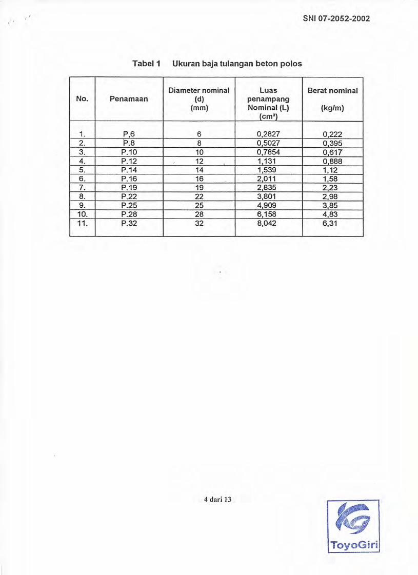
PLAIN DEFORMEDSNI 07-2052-2002
( kg / mm2 )PLAINTYPE
PLAIN and DEFORMED

UKURAN BAJA TULANGAN BETON ULIR / SIRIPDiameter Luas Diameter Toleransi diameter
efective (De) penampang dalam (Dd) (mm) efective (cm2) (mm) (mm) 1 mtr 12 mtr batang lot
1 S.6 6 0.2827 5.5 ±0,3 (5,70 - 6,30) 0.222 2,66 ±7 ±6 2 S.8 8 0.5027 7.3 ±0,4 (7,60 - 8,40) 0.395 4,74 ±7 ±6 3 S.10 10 0.7854 8.9 ±0,4 (9,60 - 10,40) 0.617 7,40 ±6 ±5 4 S.13 13 1.327 12.0 ±0,4 (12,60 - 13,40) 1.04 12,48 ±6 ±5 5 S.16 16 2.011 15.0 ±0,5 (15,50 - 16,50) 1.58 18,96 ±5 ±4 6 S.19 19 2.835 17.8 ±0,5 (18,50 - 19,50) 2.23 26,76 ±5 ±4 7 S.22 22 3.801 20.7 ±0,5 (21,50 - 22,50) 2.98 35,76 ±5 ±4 8 S.25 25 4.909 23.6 ±0,5 (24,50 - 25,50) 3.85 46,20 ±5 ±4 9 S.29 29 6.625 27.2 ±0,6 (28,40 - 29,60) 5.20 62,28 ±4 ±3,5
10 S.32 32 8.042 30.2 ±0,6 (31,40 - 32,60) 6.31 75,72 ±4 ±3,511 S.36 36 10.18 34.0 ±0,8 (35,20 - 36,80) 7.99 95,,88 ±4 ±3,512 S.40 40 12.57 38.0 ±0,8 (39,20 - 40,80) 9.86 118,32 ±4 ±3,513 S.50 50 19.64 48.0 ±0,8 (49,20 - 50,80) 15.41 184,92 ±4 ±3,5
UKURAN BAJA TULANGAN BETON POLOSDiameter Luas
nominal (D) penampang (mm) efective (cm2) 1 mtr 12 mtr batang lot
1 P.6 6 0.2827 0.222 2,66 ±7 ±6 2 P.8 8 0.5027 0.395 4,74 ±7 ±6 3 P.10 10 0.7854 0.617 7,40 ±6 ±5 4 P.12 12 1.1310 0.888 10.66 ±6 ±5 5 P.14 14 1.539 1,12 13,44 ±6 ±5 6 P.16 16 2.011 1.58 18,96 ±5 ±4 7 P.19 19 2.835 2.23 26,76 ±5 ±4 8 P.22 22 3.801 2.98 35,76 ±5 ±4 9 P.25 25 4.909 3.85 46,20 ±5 ±4
10 P.28 28 6.158 4.83 62,28 ±4 ±3,511 P.32 32 8.042 6.31 75,72 ±4 ±3,5
SIFAT MEKANIS
No. Batas Ulur Kuat Tarik RegangBatang Uji kgf/mm2 kgf/mm2 Min
(N/mm2) (N/mm2) %No. 2 Min 24 Min 39 20 minNo. 3 (235) (380) 24 minNo. 2 Min 30 Min 45 18 minNo. 3 (295) (440) 20 minNo. 2 Min 30 Min 45 16 minNo. 3 (295) (440) 18 minNo. 2 Min 35 Min 50 18 min 3 x d 4 x dNo. 3 (345) (490) 20 minNo. 2 Min 40 Min 57 16 minNo. 3 (390) (560) 18 minNo. 2 Min 50 Min 63 12 minNo. 3 (490) (620) 14 min 90o
180o
DiameterPelengkung
3 x d180o
180o
180o
6 x d
5 x d
3 x d4 x d3 x d4 x d
5 x d
5 x d
NO PENAMAAN
PT. TOYOGIRI IRON STEELSNI 07-2052-2002
Berat (Kg)
Toleransi berat ( %)
NO PENAMAANBerat Toleransi berat
(Kg) ( %)Toleransi diameter
(mm)
±0,3 (5,70 - 6,30)±0,4 (7,60 - 8,40)
±0,4 (9,60 - 10,40)±0,4 (11,60 - 13,40)
±0,5 (15,50 - 16,50)±0,5 (18,50 - 19,50)±0,5 (21,50 - 22,50)±0,5 (24,50 - 25,50)±0,6 (27,40 - 28,60)±0,6 (31,40 - 32,60)
±0,4 (13,60 - 14,40)
Uji LengkungUji Tarik
Bj TS 50
Kelas BajaTulangan
Bj TP 24
Bj TP 30
Bj TS 30180o
SudutLengkung
Bj TS 35
Bj TS 40


Nominal Nominal Nominal Unit Mass Maximum Value Minimum Value AngleDiameter Peripheral Sectional of Mean Interval of Sum of between
Length Area between Knots Min Value Max Value Clearance Knot and(d) (l) (S) mm mm between Knots Axial Linemm cm cm2 kg/m mm mm
D 6 6.35 2.0 0.3167 0.249 4.4 0.3 0.6 5.0D 10 9.53 3.0 0.7133 0.56 6.7 0.4 0.8 7.5D 13 12.7 4.0 1.267 0.995 8.9 0.5 1.0 10.0D 16 15.9 5.0 1.986 1.56 11.1 0.7 1.4 12.5D 19 19.1 6.0 2.865 2.25 13.4 1.0 2.0 15.0D 22 22.2 7.0 3.871 3.04 15.5 1.1 2.2 17.5D 25 25.4 8.0 5.067 3.98 17.8 1.3 2.6 20.0D 29 28.6 9.0 6.424 5.04 20 1.4 2.8 22.5D 32 31.8 10.0 7.942 6.23 22.3 1.6 3.2 25.0D 35 34.9 11.0 9.566 7.51 24.4 1.7 3.4 27.5D 38 38.1 12.0 11.400 8.95 26.7 1.9 3.8 30.0D 41 41.3 13.0 13.400 10.5 28.9 2.1 4.2 32.5D 51 50.8 16.0 20.270 15.9 35.6 2.5 5.0 40.0
Yield Point or TensileSymbol of 0.2 % Proof Strength Tensile Test
Grade Stress PieceN/mm2 N/mm2 % Bend Angle
No. 2 20 minNo. 3 24 min
Equivalent toNo. 2
Equivalent toNo. 3
Equivalent toNo. 2
Equivalent toNo. 3
Equivalent toNo. 2
Equivalent toNo. 3
Equivalent toNo. 2
Equivalent toNo. 3
Equivalent toNo. 2
Equivalent toNo. 3
Up to and Incl. D 252.5 X Nominal DiamterOver D 253 X Nominal Diameter
Over D 162 X Nominal DiameterUp to and Incl. D 161.5 X Nominal DiameterOver D 16 Up to and Incl. D 41
2.5 X Nominal Diameter
Diameter up to and Incl. D 16 mm1.5 X Nominal DiameterDiameter over D 16 mm2 X Nominal Diameter
D 512 X Nominal Diameter
Up to and Incl. D 161.5 X Nominal DiameterOver D 16
SD 390 390 to 510 560 min
SD 490 490 to 625 620 min
SD 345 345 to 440 490 min
16 min
18 min
16 min
18 min
18 min
20 min
SD 295A 440 to 600
SD 295B 295 to 390 440 min
SR 235 235 min 380 to 520
SR 295 295 min
180o
90o
No. 2 18 min
No. 3 20 min
16 min
18 min
12 min
14 min
Inside Radius
180o
180o
180o
180o
180o
1.5 X Nominal Diameter
2 X Nominal DiameterUp to and Incl. D 16
2.5 X Nominal Diameter
PT. TOYOGIRI IRON STEEL
1.5 X Nominal Diameter
JIS G 3112
Height of Knot
Designation
45o min
BendabilityElongation
440 to 600
295 min

Designation: A 615/A 615M – 04a American Association State Highway andTransportation Officials Standard
AASHTO No.: M 31
Standard Specification forDeformed and Plain Carbon Steel Bars for ConcreteReinforcement 1
This standard is issued under the fixed designation A 615/A 615M; the number immediately following the designation indicates the yearof original adoption or, in the case of revision, the year of last revision. A number in parentheses indicates the year of last reapproval.A superscript epsilon (e) indicates an editorial change since the last revision or reapproval.
This standard has been approved for use by agencies of the Department of Defense.
1. Scope*
1.1 This specification covers deformed and plain carbonsteel bars for concrete reinforcement in cut lengths and coils.Steel bars containing alloy additions, such as with the AISI andSAE series of alloy steels, are permitted if the resulting productmeets all the other requirements of this specification. Thestandard sizes and dimensions of deformed bars and theirnumber designations are given in Table 1. The text of thisspecification references notes and footnotes which provideexplanatory material. These notes and footnotes (excludingthose in tables and figures) shall not be considered as require-ments of the specification.
1.2 Bars are of three minimum yield levels: namely, 40 000[280 MPa], 60 000 [420 MPa], and 75 000 psi [520 MPa],designated as Grade 40 [280], Grade 60 [420], and Grade 75[520], respectively.
1.3 Hot-rolled plain rounds, in sizes up to and including 2in. [50.8 mm] in diameter in coils or cut lengths, whenspecified for dowels, spirals and structural ties or supports shallbe furnished under this specification in Grade 40 [280], Grade60 [420], and Grade 75 [520]. For ductility properties (elon-gation and bending), test provisions of the nearest smallernominal diameter deformed bar size shall apply. Requirementsproviding for deformations and marking shall not be appli-cable.
NOTE 1—Welding of the material in this specification should beapproached with caution since no specific provisions have been includedto enhance its weldability. When steel is to be welded, a weldingprocedure suitable for the chemical composition and intended use orservice should be used. The use of the latest edition of ANSI/AWS D 1.4is recommended. This document describes the proper selection of the fillermetals, preheat/interpass temperatures, as well as, performance andprocedure qualification requirements.
1.4 This specification is applicable for orders in eitherinch-pound units (as Specification A 615) or in SI units (asSpecification A 615M).
1.5 The values stated in either inch-pound units or SI unitsare to be regarded as standard. Within the text, the SI units areshown in brackets. The values stated in each system are notexact equivalents; therefore, each system must be used inde-pendently of the other. Combining values from the two systemsmay result in nonconformance with the specification.
2. Referenced Documents
2.1 ASTM Standards:2
A 6/A 6M Specification for General Requirements forRolled Structural Steel Bars, Plates, Shapes, and SheetPiling
A 370 Test Methods and Definitions for Mechanical Testingof Steel Products
A 510 Specification for General Requirements for WireRods and Coarse Round Wire, Carbon Steel
A 510M Specification for General Requirements for WireRods and Coarse Round Wire, Carbon Steel (Metric)
A 700 Practices for Packaging, Marking, and LoadingMethods for Steel Products for Domestic Shipment
A 706/A 706M Specification for Low-Alloy Steel De-formed and Plain Bars for Concrete Reinforcement
E 29 Practice for Using Significant Digits in Test Data toDetermine Conformance with Specifications
2.2 AWS Standard:ANSI/AWS D 1.4 Structural Welding Code—Reinforcing
Steel3
2.3 U.S. Military Standards:MIL-STD-129 Marking for Shipment and Storage4
MIL-STD-163 Steel Mill Products Preparation for Ship-ment and Storage4
2.4 U.S. Federal Standard:Fed. Std. No. 123 Marking for Shipment (Civil Agencies)4
1 This specification is under the jurisdiction of ASTM Committee A01 on Steel,Stainless Steel, and Related Alloys and is the direct responsibility of SubcommitteeA01.05 on Steel Reinforcement.
Current edition approved May 1, 2004. Published May 2004. Originallyapproved in 1968. Last previous edition approved in 2004 as A 615/A 615M – 04.
2 For referenced ASTM standards, visit the ASTM website, www.astm.org, orcontact ASTM Customer Service at [email protected]. ForAnnual Book of ASTMStandardsvolume information, refer to the standard’s Document Summary page onthe ASTM website.
3 Available from American Welding Society, 550 N.W. LeJeune Road, P.O. Box351040, Miami, FL 33135.
4 Available from Standardization Documents Order Desk, Bldg. 4 Section D, 700Robbins Ave., Philadelphia, PA 19111-5094, Attn: NPODS.
1
*A Summary of Changes section appears at the end of this standard.
Copyright © ASTM International, 100 Barr Harbor Drive, PO Box C700, West Conshohocken, PA 19428-2959, United States.
3. Terminology
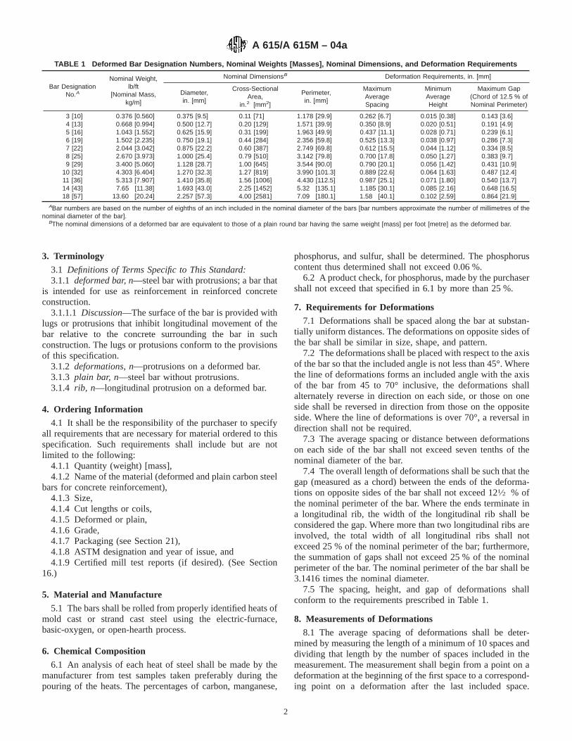
3.1 Definitions of Terms Specific to This Standard:3.1.1 deformed bar, n—steel bar with protrusions; a bar that
is intended for use as reinforcement in reinforced concreteconstruction.
3.1.1.1 Discussion—The surface of the bar is provided withlugs or protrusions that inhibit longitudinal movement of thebar relative to the concrete surrounding the bar in suchconstruction. The lugs or protusions conform to the provisionsof this specification.
3.1.2 deformations, n—protrusions on a deformed bar.3.1.3 plain bar, n—steel bar without protrusions.3.1.4 rib, n—longitudinal protrusion on a deformed bar.
4. Ordering Information
4.1 It shall be the responsibility of the purchaser to specifyall requirements that are necessary for material ordered to thisspecification. Such requirements shall include but are notlimited to the following:
4.1.1 Quantity (weight) [mass],4.1.2 Name of the material (deformed and plain carbon steel
bars for concrete reinforcement),4.1.3 Size,4.1.4 Cut lengths or coils,4.1.5 Deformed or plain,4.1.6 Grade,4.1.7 Packaging (see Section 21),4.1.8 ASTM designation and year of issue, and4.1.9 Certified mill test reports (if desired). (See Section
16.)
5. Material and Manufacture
5.1 The bars shall be rolled from properly identified heats ofmold cast or strand cast steel using the electric-furnace,basic-oxygen, or open-hearth process.
6. Chemical Composition
6.1 An analysis of each heat of steel shall be made by themanufacturer from test samples taken preferably during thepouring of the heats. The percentages of carbon, manganese,
phosphorus, and sulfur, shall be determined. The phosphoruscontent thus determined shall not exceed 0.06 %.
6.2 A product check, for phosphorus, made by the purchasershall not exceed that specified in 6.1 by more than 25 %.
7. Requirements for Deformations
7.1 Deformations shall be spaced along the bar at substan-tially uniform distances. The deformations on opposite sides ofthe bar shall be similar in size, shape, and pattern.
7.2 The deformations shall be placed with respect to the axisof the bar so that the included angle is not less than 45°. Wherethe line of deformations forms an included angle with the axisof the bar from 45 to 70° inclusive, the deformations shallalternately reverse in direction on each side, or those on oneside shall be reversed in direction from those on the oppositeside. Where the line of deformations is over 70°, a reversal indirection shall not be required.
7.3 The average spacing or distance between deformationson each side of the bar shall not exceed seven tenths of thenominal diameter of the bar.
7.4 The overall length of deformations shall be such that thegap (measured as a chord) between the ends of the deforma-tions on opposite sides of the bar shall not exceed 121⁄2 % ofthe nominal perimeter of the bar. Where the ends terminate ina longitudinal rib, the width of the longitudinal rib shall beconsidered the gap. Where more than two longitudinal ribs areinvolved, the total width of all longitudinal ribs shall notexceed 25 % of the nominal perimeter of the bar; furthermore,the summation of gaps shall not exceed 25 % of the nominalperimeter of the bar. The nominal perimeter of the bar shall be3.1416 times the nominal diameter.
7.5 The spacing, height, and gap of deformations shallconform to the requirements prescribed in Table 1.
8. Measurements of Deformations
8.1 The average spacing of deformations shall be deter-mined by measuring the length of a minimum of 10 spaces anddividing that length by the number of spaces included in themeasurement. The measurement shall begin from a point on adeformation at the beginning of the first space to a correspond-ing point on a deformation after the last included space.
TABLE 1 Deformed Bar Designation Numbers, Nominal Weights [Masses], Nominal Dimensions, and Deformation Requirements
Bar DesignationNo.A
Nominal Weight,lb/ft
[Nominal Mass,kg/m]
Nominal DimensionsB Deformation Requirements, in. [mm]
Diameter,in. [mm]
Cross-SectionalArea,
in.2 [mm2]
Perimeter,in. [mm]
MaximumAverageSpacing
MinimumAverageHeight
Maximum Gap(Chord of 12.5 % ofNominal Perimeter)
3 [10] 0.376 [0.560] 0.375 [9.5] 0.11 [71] 1.178 [29.9] 0.262 [6.7] 0.015 [0.38] 0.143 [3.6]4 [13] 0.668 [0.994] 0.500 [12.7] 0.20 [129] 1.571 [39.9] 0.350 [8.9] 0.020 [0.51] 0.191 [4.9]5 [16] 1.043 [1.552] 0.625 [15.9] 0.31 [199] 1.963 [49.9] 0.437 [11.1] 0.028 [0.71] 0.239 [6.1]6 [19] 1.502 [2.235] 0.750 [19.1] 0.44 [284] 2.356 [59.8] 0.525 [13.3] 0.038 [0.97] 0.286 [7.3]7 [22] 2.044 [3.042] 0.875 [22.2] 0.60 [387] 2.749 [69.8] 0.612 [15.5] 0.044 [1.12] 0.334 [8.5]8 [25] 2.670 [3.973] 1.000 [25.4] 0.79 [510] 3.142 [79.8] 0.700 [17.8] 0.050 [1.27] 0.383 [9.7]9 [29] 3.400 [5.060] 1.128 [28.7] 1.00 [645] 3.544 [90.0] 0.790 [20.1] 0.056 [1.42] 0.431 [10.9]
10 [32] 4.303 [6.404] 1.270 [32.3] 1.27 [819] 3.990 [101.3] 0.889 [22.6] 0.064 [1.63] 0.487 [12.4]11 [36] 5.313 [7.907] 1.410 [35.8] 1.56 [1006] 4.430 [112.5] 0.987 [25.1] 0.071 [1.80] 0.540 [13.7]14 [43] 7.65 [11.38] 1.693 [43.0] 2.25 [1452] 5.32 [135.1] 1.185 [30.1] 0.085 [2.16] 0.648 [16.5]18 [57] 13.60 [20.24] 2.257 [57.3] 4.00 [2581] 7.09 [180.1] 1.58 [40.1] 0.102 [2.59] 0.864 [21.9]
ABar numbers are based on the number of eighths of an inch included in the nominal diameter of the bars [bar numbers approximate the number of millimetres of thenominal diameter of the bar].
BThe nominal dimensions of a deformed bar are equivalent to those of a plain round bar having the same weight [mass] per foot [metre] as the deformed bar.
A 615/A 615M – 04a
2

Spacing measurments shall not be made over a bar areacontaining bar marking symbols involving letters or numbers.
8.2 The average height of deformations shall be determinedfrom measurements made on not less than two typical defor-mations. Determinations shall be based on three measurementsper deformation, one at the center of the overall length and theother two at the quarter points of the overall length.
8.3 Insufficient height, insufficient circumferential cover-age, or excessive spacing of deformations shall not constitutecause for rejection unless it has been clearly established bydeterminations on each lot (Note 2) tested that typical defor-mation height, gap, or spacing do not conform to the minimumrequirements prescribed in Section 7. No rejection shall bemade on the basis of measurements if fewer than ten adjacentdeformations on each side of the bar are measured.
NOTE 2—As used within the intent of 8.3, the term “lot” shall mean allthe bars of one bar size and pattern of deformations contained in anindividual shipping release or shipping order.
9. Tensile Requirements
9.1 The material, as represented by the test specimens, shallconform to the requirements for tensile properties prescribed inTable 2.
9.2 The yield point or yield strength shall be determined byone of the following methods:
9.2.1 The yield point shall be determined by drop of thebeam or halt in the gage of the testing machine.
9.2.2 Where the steel tested does not have a well-definedyield point, the yield strength shall be determined by readingthe stress corresponding to the prescribed strain using anautographic diagram method or an extensometer as describedin Test Methods and Definitions A 370. The strain shall be0.5 % of gage length for Grade 40 [280] and Grade 60 [420]and shall be 0.35 % of gage length for Grade 75 [520]. Whenmaterial is furnished in coils, the test sample shall be straight-ened prior to placing it in the jaws of the tensile machine.Straightening shall be done carefully to avoid formation oflocal sharp bends and to minimize cold work. Insufficientstraightening prior to attaching the extensometer can result inlower-than-actual yield strength readings.
9.3 The percentage of elongation shall be as prescribed inTable 2.
10. Bending Requirements
10.1 The bend-test specimen shall withstand being bentaround a pin without cracking on the outside radius of the bentportion. The requirements for degree of bending and sizes ofpins are prescribed in Table 3. When material is furnished incoils, the test sample shall be straightened prior to placing it inthe bend tester.
10.2 The bend test shall be made on specimens of sufficientlength to ensure free bending and with apparatus whichprovides:
10.2.1 Continuous and uniform application of forcethroughout the duration of the bending operation.
10.2.2 Unrestricted movement of the specimen at points ofcontact with the apparatus and bending around a pin free torotate.
10.2.3 Close wrapping of the specimen around the pinduring the bending operation.
10.3 It is permissible to use more severe methods of bendtesting, such as placing a specimen across two pins free torotate and applying the bending force with a fixed pin. Whenfailures occur under more severe methods, retests shall bepermitted under the bend-test method prescribed in 10.2.
11. Permissible Variation in Weight [Mass]
11.1 Deformed reinforcing bars shall be evaluated on thebasis of nominal weight [mass]. The weight [mass] determinedusing the measured weight [mass] of the test specimen androunding in accordance with Practice E 29, shall be at least 94% of the applicable weight [mass] per unit length prescribed inTable 1. In no case shall overweight [excess mass] of anydeformed bar be the cause for rejection. Weight [mass]variation for plain rounds shall be computed on the basis ofpermissible variation in diameter. For plain bars smaller than3⁄8in. [9.5 mm], use Specification A 510 [Specification A 510M].For larger bars up to and including 2 in. [50.8 mm], useSpecification A 6/A 6M.
12. Finish
12.1 The bars shall be free of detrimental surface imperfec-tions.
12.2 Rust, seams, surface irregularities, or mill scale shallnot be cause for rejection, provided the weight, dimensions,cross-sectional area, and tensile properties of a hand wirebrushed test specimen are not less than the requirements of thisspecification.
12.3 Surface imperfections or flaws other than those speci-fied in 12.2 shall be considered detrimental when specimenscontaining such imperfections fail to conform to either tensile
TABLE 2 Tensile Requirements
Grade 40[280]A
Grade 60[420]
Grade 75[520]B
Tensile strength, min, psi[MPa]
60 000 [420] 90 000 [620] 100 000 [690]
Yield strength, min, psi[MPa]
40 000 [280] 60 000 [420] 75 000 [520]
Elongation in 8 in. [203.2mm], min, %:
Bar Designation No.3 [10] 11 9 . . .4, 5 [13, 16] 12 9 . . .6 [19] 12 9 77, 8 [22, 25] . . . 8 79, 10, 11 [29, 32, 36] . . . 7 614, 18 [43, 57] . . . 7 6
AGrade 40 [280] bars are furnished only in sizes 3 through 6 [10 through 19].BGrade 75 [520] bars are furnished only in sizes 6 through 18 [19 through 57].
TABLE 3 Bend Test Requirements
Bar Designation No.Pin Diameter for Bend TestsA
Grade 40 [280] Grade 60 [420] Grade 75 [520]
3, 4, 5 [10, 13, 16] 31⁄2 d B 31⁄2 d . . .6 [19] 5d 5d 5d7, 8 [22, 25] . . . 5d 5d9, 10, 11 [29, 32, 36] . . . 7d 7d14, 18 [43, 57] (90°) . . . 9d 9d
ATest bends 180° unless noted otherwise.Bd = nominal diameter of specimen.
A 615/A 615M – 04a
3

or bending requirements. Examples include, but are not limitedto, laps, seams, scabs, slivers, cooling or casting cracks, andmill or guide marks.
NOTE 3—Reinforcing bar intended for epoxy coating applicationsshould have surfaces with a minimum of sharp edges to achieve propercover. Particular attention should be given to bar marks and deformationswhere coating difficulties are prone to occur.
NOTE 4—Deformed bars destined to be mechanically-spliced or butt-welded may require a certain degree of roundness in order for the splicesto adequately achieve strength requirements.
13. Number of Tests
13.1 For bar sizes No. 3 to 11 [10 to 36], inclusive, onetension test and one bend test shall be made of the largest sizerolled from each heat. If, however, material from one heatdiffers by three or more designation numbers, one tension andone bend test shall be made from both the highest and lowestdesignation number of the deformed bars rolled.
13.2 For bar sizes Nos. 14 and 18 [43 and 57], one tensiontest and one bend test shall be made of each size rolled fromeach heat.
13.3 For all bar sizes one set of dimensional property testsincluding bar weight [mass] and spacing, height, and gap ofdeformations shall be made of each bar size rolled from eachheat.
14. Retests
14.1 If any tensile property of any tension test specimen isless than that specified, and any part of the fracture is outsidethe middle third of the gage length, as indicated by scribescratches marked on the specimen before testing, a retest shallbe allowed.
14.2 If the results of an original tension specimen fail tomeet the specified minimum requirements and are within 2000psi [14 MPa] of the required tensile strength, within 1000 psi[7 MPa] of the required yield point, or within two percentageunits of the required elongation, a retest shall be permitted ontwo random specimens for each original tension specimenfailure from the lot. Both retest specimens shall meet therequirements of this specification.
14.3 If a bend test fails for reasons other than mechanicalreasons or flaws in the specimen as described in 14.5 and 14.6,a retest shall be permitted on two random specimens from thesame lot. Both retest specimens shall meet the requirements ofthis specification. The retest shall be performed on test speci-mens that are at air temperature but not less than 60°F [16°C].
14.4 If a weight [mass] test fails for reasons other than flawsin the specimen as described in 14.6, a retest shall be permittedon two random specimens from the same lot. Both retestspecimens shall meet the requirements of this specification.
14.5 If any test specimen fails because of mechanicalreasons such as failure of testing equipment or improperspecimen preparation, a replacement specimen shall be permit-ted.
14.6 If flaws are detected in a test specimen, either before orduring the performance of the test, a replacement specimenshall be permitted from the same heat and bar size as theoriginal.
15. Test Specimens
15.1 All mechanical tests shall be conducted in accordancewith Test Methods and Definitions A 370 including Annex A9.
15.2 Tension test specimens shall be the full section of thebar as rolled. The unit stress determination shall be based onthe nominal bar area.
15.3 The bend-test specimens shall be the full section of thebar as rolled.
16. Test Reports
16.1 When specified in the purchase order, the followinginformation shall be reported on a per heat basis. Reportadditonal items as requested or desired.
16.1.1 Chemical analysis including carbon, manganese,phosphorus, and sulfur.
16.1.2 Tensile properties.
16.1.3 Bend test.
16.2 A Material Test Report, Certificate of Inspection, orsimilar document printed from or used in electronic form froman electronic data interchange (EDI) transmission shall beregarded as having the same validity as a counterpart printed inthe certifier’s facility. The content of the EDI transmitteddocument must meet the requirements of the invoked ASTMstandard(s) and conform to any EDI agreement between thepurchaser and the supplier. Notwithstanding the absence of asignature, the organization submitting the EDI transmission isresponsible for the content of the report.
NOTE 5—The industry definition invoked here is: EDI is the computerto computer exchange of business information in a standard format suchas ANSI ASC X12.
17. Inspection
17.1 The inspector representing the purchaser shall havefree entry, at all times while work on the contract of thepurchaser is being performed, to all parts of the manufacturer’sworks that concern the manufacture of the material ordered.The manufacturer shall afford the inspector all reasonablefacilities to satisfy him that the material is being furnished inaccordance with this specification. All tests (except productanalysis) and inspection, shall be made at the place ofmanufacture prior to shipment, unless otherwise specified, andshall be so conducted as not to interfere unnecessarily with theoperation of the works.
17.2 For Government Procurement Only— Except as oth-erwise specified in the contract, the contractor is responsiblefor the performance of all inspection and test requirementsspecified herein. The contractor shall be permitted to use hisown or any other suitable facilities for the performance of theinspection and test requirements specified herein, unless dis-approved by the purchaser at the time of purchase. Thepurchaser shall have the right to perform any of the inspectionsand tests at the same frequency as set forth in this specification,where such inspections are deemed necessary to ensure thatmaterial conforms to prescribed requirements.
A 615/A 615M – 04a
4

18. Rejection
18.1 Unless otherwise specified, any rejection based on testsmade in accordance with 6.2, shall be reported to the manu-facturer within five working days from the receipt of samplesby the purchaser.
18.2 Material that shows injurious defects subsequent to itsacceptance at the manufacturer’s works will be rejected, andthe manufacturer shall be notified.
19. Rehearing
19.1 Samples tested in accordance with 6.2 that representrejected material shall be preserved for two weeks from thedate rejection is reported to the manufacturer. In case ofdissatisfaction with the results of the tests, the manufacturershall have the right to make claim for a rehearing within thattime.
20. Marking
20.1 When loaded for mill shipment, bars shall be properlyseparated and tagged with the manufacturer’s heat or testidentification number.
20.2 Each producer shall identify the symbols of his mark-ing system.
20.3 All bars produced to this specification, except plainround bars which shall be tagged for grade, shall be identifiedby a distinguishing set of marks legibly rolled onto the surfaceof one side of the bar to denote in the following order:
20.3.1 Point of Origin—Letter or symbol established as theproducer’s mill designation.
20.3.2 Size Designation—Arabic number corresponding tobar designation number of Table 1.
20.3.3 Type of Steel—Letter S indicating that the bar wasproduced to this specification, or for Grade 60 [420] bars only,lettersS andW indicating that the bar was produced to meetboth Specifications A 615/A 615M and A 706/A 706M.
20.3.4 Minimum Yield Designation—For Grade 60 [420]bars, either the number60 [4] or a single continuous longitu-dinal line through at least five spaces offset from the center ofthe bar side. For Grade 75 [520] bars, either the number75 [5]or two continuous longitudinal lines through at least five spacesoffset each direction from the center of the bar. (No markingdesignation for Grade 40 [280] bars.)
20.3.5 It shall be permissible to substitute: a metric size barof Grade 280 for the corresponding inch-pound size bar ofGrade 40, a metric size bar of Grade 420 for the correspondinginch-pound size bar of Grade 60, and a metric size bar of Grade520 for the corresponding inch-pound size bar of Grade 75.
21. Packaging21.1 When specified in the purchase order, packaging shall
be in accordance with the procedures in Practices A 700.21.2 For Government Procurement Only— When specified
in the contract or order, and for direct procurement by or directshipment to the U.S. government, material shall be preserved,packaged, and packed in accordance with the requirements ofMIL-STD-163. The applicable levels shall be as specified inthe contract. Marking for shipment of such material shall be inaccordance with Fed. Std. No. 123 for civil agencies andMIL-STD-129 for military agencies.
22. Keywords22.1 concrete reinforcement; deformations (protrusions);
steel bars
SUMMARY OF CHANGES
Committee A01 has identified the location of the following changes to this standard since A 615/A 615M-04that may impact the use of this standard. (Approved May 1, 2004)
(1) Added 16.2 and Note 5.
Committee A01 has identified the location of the following changes to this standard since A 615/A 615M-03a that may impactthe use of this standard. (Approved Jan. 1, 2004)
(1) Revised the title.(2) Revised 1.1, 4.1.2, and 5.1.
(3) Revised 10.3 to eliminate permissive language.
A 615/A 615M – 04a
5

Committee A01 has identified the location of the following changes to this standard since A 615/A 615M-03 that may impactthe use of this standard. (Approved June 10, 2003).
(1) Deleted Note 2.(2) Revised 6.2.(3) Revised 14.5.(4) Revised 14.6.
(5) Revised 16.1.
(6) Revised 17.2.
(7) Revised 19.1.
ASTM International takes no position respecting the validity of any patent rights asserted in connection with any item mentionedin this standard. Users of this standard are expressly advised that determination of the validity of any such patent rights, and the riskof infringement of such rights, are entirely their own responsibility.
This standard is subject to revision at any time by the responsible technical committee and must be reviewed every five years andif not revised, either reapproved or withdrawn. Your comments are invited either for revision of this standard or for additional standardsand should be addressed to ASTM International Headquarters. Your comments will receive careful consideration at a meeting of theresponsible technical committee, which you may attend. If you feel that your comments have not received a fair hearing you shouldmake your views known to the ASTM Committee on Standards, at the address shown below.
This standard is copyrighted by ASTM International, 100 Barr Harbor Drive, PO Box C700, West Conshohocken, PA 19428-2959,United States. Individual reprints (single or multiple copies) of this standard may be obtained by contacting ASTM at the aboveaddress or at 610-832-9585 (phone), 610-832-9555 (fax), or [email protected] (e-mail); or through the ASTM website(www.astm.org).
A 615/A 615M – 04a
6
Designation: A 706/A 706M – 04a
Standard Specification forLow-Alloy Steel Deformed and Plain Bars for ConcreteReinforcement 1
This standard is issued under the fixed designation A 706/A 706M; the number immediately following the designation indicates the yearof original adoption or, in the case of revision, the year of last revision. A number in parentheses indicates the year of last reapproval.A superscript epsilon (e) indicates an editorial change since the last revision or reapproval.
This standard has been approved for use by agencies of the Department of Defense.
1. Scope*
1.1 General—This specification covers deformed and plainlow-alloy steel bars in cut lengths or coils for concretereinforcement intended for applications where restrictive me-chanical properties and chemical composition are required forcompatibility with controlled tensile property applications or toenhance weldability. The standard sizes and dimensions ofdeformed bars and their number designations are given inTable 1. The text of this specification references notes andfootnotes that provide explanatory material. These notes andfootnotes, excluding those in tables and figures, shall not beconsidered as requirements of this specification.
1.2 Grade—Bars are of a single minimum yield strengthlevel: namely, 60 000 psi [420 MPa], designated as Grade 60[420].
1.3 Plain rounds, in sizes up to and including 2 in. [50.8mm] in diameter in coils or cut lengths, when ordered, shall befurnished under this specification. For ductility properties(elongation and bending), test provisions of the nearest smallernominal diameter deformed bar size shall apply.
1.4 Controlled Tensile Properties—This specification limitsmechanical properties (Table 2) to provide the desired yield/tensile properties for controlled tensile property applications.
1.5 Welding—This specification limits chemical composi-tion (6.2) and carbon equivalent (6.4) to enhance the weldabil-ity of the material. When steel is to be welded, a weldingprocedure suitable for the chemical composition and intendeduse or service should be used. The use of the latest edition ofANSI/AWS D1.4 is recommended. This document describesthe proper selection of the filler metals, preheat/interpasstemperatures, as well as, performance and procedure qualifi-cation requirements.
1.6 This specification is applicable for orders in eitherinch-pound units (Specification A 706) or in SI units [Specifi-cation A 706M].
1.7 The values stated in either inch-pound units or SI unitsare to be regarded as standard. Within the text, the SI units areshown in brackets. The values stated in each system are notexact equivalents; therefore, each system must be used inde-pendently of the other. Combining values from the two systemsmay result in nonconformance with this specification.
2. Referenced Documents
2.1 ASTM Standards:2
A 6/A 6M Specification for General Requirements forRolled Structural Steel Bars, Plates, Shapes, and SteelPiling
A 370 Test Methods and Definitions for Mechanical Testingof Steel Products
A 510 Specification for General Requirements for WireRods and Coarse Round Wire, Carbon Steel
A 510M Specification for General Requirements for WireRods and Coarse Round Wire, Carbon Steel (Metric)
A 615/A 615M Specification for Deformed and Plain Billet-Steel Bars for Concrete Reinforcement
A 700 Practices for Packaging, Marking, and LoadingMethods for Steel Products for Domestic Shipment
A 751 Test Methods, Practices, and Terminology forChemical Analysis of Steel Products
E 29 Practice for Using Significant Digits in Test Data toDetermine Conformance with Specifications
2.2 ANSI/AWS Standard:AWS D1.4 Structural Welding Code—Reinforcing Steel3
2.3 Government Standards:MIL-STD-129 Marking for Shipment and Storage4
MIL-STD-163 Steel Mill Products Preparation for Ship-ment and Storage4
2.4 U.S. Federal Standard:
1 This specification is under the jurisdiction of ASTM Committee A01 on Steel,Stainless Steel, and Related Alloys and is the direct responsibility of SubcommitteeA01.05 on Steel Reinforcement.
Current edition approved May 1, 2004. Published May 2004. Originallyapproved in 1974. Last previous edition approved in 2004 as A 706/A 706M – 04.
2 For referenced ASTM standards, visit the ASTM website, www.astm.org, orcontact ASTM Customer Service at [email protected]. ForAnnual Book of ASTMStandardsvolume information, refer to the standard’s Document Summary page onthe ASTM website.
3 Available from the American Welding Society, P.O. Box 351040, 550 N.W. LeJeune Rd., Miami, FL 33126.
4 Available from Standardization Documents Order Desk, Bldg. 4 Section D, 700Robbins Ave., Philadelphia, PA 19111-5094, Attn: NPODS.
1
*A Summary of Changes section appears at the end of this standard.
Copyright © ASTM International, 100 Barr Harbor Drive, PO Box C700, West Conshohocken, PA 19428-2959, United States.

Fed. Std. No. 123 Marking for Shipment (Civil Agencies)4
3. Terminology
3.1 Definitions of Terms Specific to This Standard:3.1.1 deformations, n—protrusions on a deformed bar.3.1.2 deformed bar, n—steel bar with protrusions; a bar
that is intended for use as reinforcement in reinforced concreteand related construction.
3.1.3 Discussion—The surface of the bar is provided withlugs or protrusions that inhibit longitudinal movement of thebar relative to the concrete surrounding the bar in suchconstruction. The lugs or protrusions conform to the provisionsof this specification.
3.1.4 plain bar, n—steel bar without protrusions.3.1.5 rib, n— longitudinal protrusions on a deformed bar.
4. Ordering Information
4.1 It shall be the responsibility of the purchaser to specifyall requirements that are necessary for material ordered to thisspecification. Such requirements shall include, but are notlimited to, the following:
4.1.1 Quantity (weight) [mass],4.1.2 Name of material (low-alloy steel deformed and plain
bars for concrete reinforcement),4.1.3 Size,4.1.4 Cut lengths or coils,4.1.5 Deformed or plain,4.1.6 Packaging (see Section 17),4.1.7 ASTM designation and year of issue.
5. Material and Manufacture
5.1 The bars shall be processed from properly identifiedheats of mold cast or strand cast steel.
5.2 The steel shall be made by one of the followingprocesses: electric-furnace, basic-oxygen, or open-hearth.
6. Chemical Composition
6.1 The chemical analysis of each heat shall be determinedin accordance with Test Methods A 751. The manufacturershall make the analysis on test samples taken preferably duringthe pouring of the heat. The percentages of carbon, manganese,phosphorus, sulfur, silicon, copper, nickel, chromium, molyb-denum, and vanadium shall be determined.
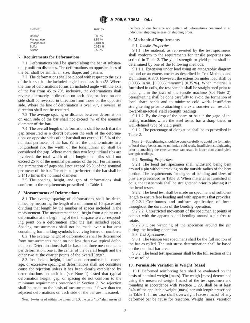
6.2 The chemical composition as shown by heat analysisshall be limited by the following:
Element max, %
CarbonManganese
0.301.50
Phosphorus 0.035Sulfur 0.045Silicon 0.50
6.3 Choice and use of alloying elements, combined withcarbon, phosphorus, and sulfur to give the mechanical proper-ties prescribed in Table 2 and Table 3, shall be made by themanufacturer. Elements commonly used include manganese,silicon, copper, nickel, chromium, molybdenum, vanadium,columbium, titanium, and zirconium.
6.4 The heat analysis shall be such as to provide a carbonequivalent (C.E.) not exceeding 0.55 % as calculated by thefollowing formula:
C.E.5 %C1% Mn
6 1% Cu
40 1% Ni20 1
% Cr10 2
% Mo50 2
% V10
(1)
6.5 Product (Check) Verification Analysis—A product checkanalysis made by the purchaser shall not exceed the followingpercentages:
TABLE 1 Deformed Bar Designation Numbers, Nominal Weights [Masses], Nominal Dimensions, and Deformation Requirements
BarDesig-nationNo.A
Nominal Weight, lb/ft[Nominal Mass,
kg/m]
Nominal DimensionsB Deformation Requirements, in. [mm]
Diameter,in. [mm]
Cross-Sectional Areain.2 [mm2]
Perimeter,in. [mm]
Maximum AverageSpacing
Minimum AverageHeight
Maximum Gap(Chord of 12.5 % ofNominal Perimeter)
3 [10] 0.376 [ 0.560] 0.375 [ 9.5] 0.11 [ 71] 1.178 [ 29.9] 0.262 [ 6.7] 0.015 [0.38] 0.143 [ 3.6]4 [13] 0.668 [ 0.994] 0.500 [12.7] 0.20 [ 129] 1.571 [ 39.9] 0.350 [ 8.9] 0.020 [0.51] 0.191 [ 4.9]5 [16] 1.043 [ 1.552] 0.625 [15.9] 0.31 [ 199] 1.963 [ 49.9] 0.437 [11.1] 0.028 [0.71] 0.239 [ 6.1]6 [19] 1.502 [ 2.235] 0.750 [19.1] 0.44 [ 284] 2.356 [ 59.8] 0.525 [13.3] 0.038 [0.97] 0.286 [ 7.3]7 [22] 2.044 [ 3.042] 0.875 [22.2] 0.60 [ 387] 2.749 [ 69.8] 0.612 [15.5] 0.044 [1.12] 0.334 [ 8.5]8 [25] 2.670 [ 3.973] 1.000 [25.4] 0.79 [ 510] 3.142 [ 79.8] 0.700 [17.8] 0.050 [1.27] 0.383 [ 9.7]9 [29] 3.400 [ 5.060] 1.128 [28.7] 1.00 [ 645] 3.544 [ 90.0] 0.790 [20.1] 0.056 [1.42] 0.431 [10.9]
10 [32] 4.303 [ 6.404] 1.270 [32.3] 1.27 [ 819] 3.990 [101.3] 0.889 [22.6] 0.064 [1.63] 0.487 [12.4]11 [36] 5.313 [ 7.907] 1.410 [35.8] 1.56 [1006] 4.430 [112.5] 0.987 [25.1] 0.071 [1.80] 0.540 [13.7]14 [43] 7.65 [11.38] 1.693 [43.0] 2.25 [1452] 5.32 [135.1] 1.185 [30.1] 0.085 [2.16] 0.648 [16.5]18 [57] 13.60 [20.24] 2.257 [57.3] 4.00 [2581] 7.09 [180.1] 1.58 [40.1] 0.102 [2.59] 0.864 [21.9]
A Bar numbers are based on the number of eighths of an inch included in the nominal diameter of the bars [bar numbers approximate the number of millimetres of thenominal diameter of the bar].
B The nominal dimensions of a deformed bar are equivalent to those of a plain round bar having the same weight [mass] per foot [metre] as the deformed bar.
TABLE 2 Tensile Requirements
Tensile strength, min, psi [MPa] 80 000 [550]A
Yield strength, min, psi [MPa] 60 000 [420]Yield strength, max, psi [MPa] 78 000 [540]Elongation in 8 in. [203.2 mm], min, %Bar Designation Nos.
3, 4, 5, 6 [10, 13, 16, 19] 147, 8, 9, 10, 11 [22, 25, 29, 32, 36] 1214, 18 [43, 57] 10A Tensile strength shall not be less than 1.25 times the actual yield strength.
TABLE 3 Bend Test Requirements
Bar Designation No. Pin Diameter for 180° Bend Tests
3, 4, 5 [10, 13, 16] 3dA
6, 7, 8 [19, 22, 25] 4d9, 10, 11 [29, 32, 36] 6d14, 18 [43, 57] 8d
A d = nominal diameter of specimen.
A 706/A 706M – 04a
2
Element max, %
CarbonManganese
0.33 %1.56 %
Phosphorus 0.043 %Sulfur 0.053 %Silicon 0.55 %
7. Requirements for Deformations
7.1 Deformations shall be spaced along the bar at substan-tially uniform distances. The deformations on opposite sides ofthe bar shall be similar in size, shape, and pattern.
7.2 The deformations shall be placed with respect to the axisof the bar so that the included angle is not less than 45°. Wherethe line of deformations forms an included angle with the axisof the bar from 45 to 70°, inclusive, the deformations shallreverse alternately in direction on each side, or those on oneside shall be reversed in direction from those on the oppositeside. Where the line of deformation is over 70°, a reversal indirection shall not be required.
7.3 The average spacing or distance between deformationson each side of the bar shall not exceed7⁄10 of the nominaldiameter of the bar.
7.4 The overall length of deformations shall be such that thegap (measured as a chord) between the ends of the deforma-tions on opposite sides of the bar shall not exceed 12.5 % of thenominal perimeter of the bar. Where the ends terminate in alongitudinal rib, the width of the longitudinal rib shall beconsidered the gap. Where more than two longitudinal ribs areinvolved, the total width of all longitudinal ribs shall notexceed 25 % of the nominal perimeter of the bar. Furthermore,the summation of gaps shall not exceed 25 % of the nominalperimeter of the bar. The nominal perimeter of the bar shall be3.1416 times the nominal diameter.
7.5 The spacing, height, and gap of deformations shallconform to the requirements prescribed in Table 1.
8. Measurements of Deformations
8.1 The average spacing of deformations shall be deter-mined by measuring the length of a minimum of 10 spaces anddividing that length by the number of spaces included in themeasurement. The measurement shall begin from a point on adeformation at the beginning of the first space to a correspond-ing point on a deformation after the last included space.Spacing measurements shall not be made over a bar areacontaining bar marking symbols involving letters or numbers.
8.2 The average height of deformations shall be determinedfrom measurements made on not less than two typical defor-mations. Determinations shall be based on three measurementsper deformation, one at the center of the overall length and theother two at the quarter points of the overall length.
8.3 Insufficient height, insufficient circumferential cover-age, or excessive spacing of deformations shall not constitutecause for rejection unless it has been clearly established bydeterminations on each lot (see Note 1) tested that typicaldeformation height, gap, or spacing do not conform to theminimum requirements prescribed in Section 7. No rejectionshall be made on the basis of measurements if fewer than tenadjacent deformations on each side of the bar are measured.
NOTE 1—As used within the intent of 8.3, the term “lot” shall mean all
the bars of one bar size and pattern of deformations contained in anindividual shipping release or shipping order.
9. Mechanical Requirements
9.1 Tensile Properties:9.1.1 The material, as represented by the test specimens,
shall conform to the requirements for tensile properties pre-scribed in Table 2. The yield strength or yield point shall bedetermined by one of the following methods:
9.1.1.1 Extension under load using an autographic diagrammethod or an extensometer as described in Test Methods andDefinitions A 370. However, the extension under load shall be0.0035 in./in. [0.0035 mm/mm] (0.35 %). When material isfurnished in coils, the test sample shall be straightened prior toplacing it in the jaws of the tensile machine (see Note 2).Straightening shall be done carefully to avoid the formation oflocal sharp bends and to minimize cold work. Insufficientstraightening prior to attaching the extensometer can result inlower-than-actual yield strength readings.
9.1.1.2 By the drop of the beam or halt in the gage of thetesting machine, where the steel tested has a sharp-kneed orwell-defined type of yield point.
9.1.2 The percentage of elongation shall be as prescribed inTable 2.
NOTE 2—Straightening should be done carefully to avoid the formationof local sharp bends and to minimize cold work. Insufficient straighteningprior to attaching the extensometer can result in lower-than-actual yieldstrength readings.
9.2 Bending Properties:9.2.1 The bend test specimen shall withstand being bent
around a pin without cracking on the outside radius of the bentportion. The requirements for degree of bending and sizes ofpins are prescribed in Table 3. When material is furnished incoils, the test sample shall be straightened prior to placing it inthe bend tester.
9.2.2 The bend test shall be made on specimens of sufficientlength to ensure free bending and with apparatus that provides:
9.2.2.1 Continuous and uniform application of forcethroughout the duration of the bending operation,
9.2.2.2 Unrestricted movement of the specimen at points ofcontact with the apparatus and bending around a pin free torotate,
9.2.2.3 Close wrapping of the specimen around the pinduring the bending operation.
9.3 Test Specimens:9.3.1 The tension test specimens shall be the full section of
the bar as rolled. The unit stress determination shall be basedon the nominal bar area.
9.3.2 The bend test specimens shall be the full section of thebar as rolled.
10. Permissible Variation in Weight [Mass]
10.1 Deformed reinforcing bars shall be evaluated on thebasis of nominal weight [mass]. The weigh [mass] determinedusing the measured weight [mass] of the test specimen androunding in accordance with Practice E 29, shall be at least94% of the applicable weight [mass] per unit length prescribedin Table 1. In no case shall overweight [excess mass] of anydeformed bar be cause for rejection. Weight [mass] variation
A 706/A 706M – 04a
3

for plain rounds shall be computed on the basis of permissiblevariation in diameter. For plain round bars smaller than3⁄8 in.[9.5 mm], use Specification A 510 [Specification A 510M]. Forlarger bars up to and including 2 in. [50 mm], use SpecificationA 6/A 6M.
11. Finish
11.1 The bars shall be free of detrimental surface imperfec-tions.
11.2 Rust, seams, surface irregularities, or mill scale shallnot be cause for rejection, provided the weight, dimensions,cross-sectional area, and tensile properties of a hand wirebrushed test specimen are not less than the requirements of thisspecification.
11.3 Surface imperfections or flaws other than those speci-fied in 11.2 shall be considered detrimental when specimenscontaining such imperfections fail to conform to either tensileor bending requirements. Examples include, but are not limitedto, laps, seams, scabs, slivers, cooling or casting cracks, andmill or guide marks.
NOTE 3—Reinforcing bar intended for epoxy coating applicationsshould have surfaces with a minimum of sharp edges to achieve propercover. Particular attention should be given to bar marks and deformationswhere coating difficulties are prone to occur.
NOTE 4—Deformed bars destined to be mechanically-spliced or butt-welded may require a certain degree of roundness in order for the splicesto adequately achieve strength requirements.
12. Number of Tests and Retests
12.1 All mechanical tests shall be conducted in accordancewith Test Methods and Definitions A 370 including Annex A9.
12.2 Number of Tests— One tension test, one bend test, andone set of dimensional property tests including bar weight[mass] and spacing, height, and gap of deformations shall bemade of each bar size rolled from a heat.
12.3 Retests:12.3.1 If any tensile property of any tension test specimen is
less than that specified, and any part of the fracture is outsidethe middle third of the gage length, as indicated by scribescratches marked on the specimen before testing, a retest shallbe allowed.
12.3.2 If the results of an original tension specimen fail tomeet the specified minimum requirements and are within 2000psi [14 MPa] of the required tensile strength, within 1000 psi[7 MPa] of the required yield point, or within two percentageunits of the required elongation, a retest shall be permitted ontwo random specimens for each original tension specimenfailure from the lot. Both retest specimens shall meet therequirements of this specification.
12.3.3 If a bend test fails for reasons other than mechanicalreasons or flaws in the specimen as described in 12.3.5 and12.3.6, a retest shall be permitted on two random specimensfrom the same lot. Both retest specimens shall meet therequirements of this specification. The retest shall be per-formed on test specimens that are at air temperature but not lessthan 60°F [16°C].
12.3.4 If a weight [mass] test fails for reasons other thanflaws in the specimen as described in 12.3.6, a retest shall be
permitted on two random specimens from the same lot. Bothretest specimens shall meet the requirements of this specifica-tion.
12.3.5 If any test specimen fails because of mechanicalreasons such as failure of testing equipment or improperspecimen preparation, testing of a replacement specimen shallbe permitted.
12.3.6 If flaws are detected in a test specimen, either beforeor during the performance of the test, testing of a replacementspecimen shall be permitted from the same heat and bar size asthe original.
13. Test Reports
13.1 The following information shall be reported on a perheat basis. Report additional items as requested or desired.
13.1.1 Chemical analysis including carbon, manganese,phosphorous, sulfur, silicon, copper, nickel, chromium, molyb-denum, and vanadium.
13.1.2 Carbon equivalent in accordance with 6.4.13.1.3 Tensile properties.13.1.4 Bend test.13.2 A Material Test Report, Certificate of Inspection, or
similar document printed from or used in electronic form froman electronic data interchange (EDI) transmission shall beregarded as having the same validity as a counterpart printed inthe certifier’s facility. The content of the EDI transmitteddocument must meet the requirements of the invoked ASTMstandard(s) and conform to any EDI agreement between thepurchaser and the supplier. Notwithstanding the absence of asignature, the organization submitting the EDI transmission isresponsible for the content of the report.
NOTE 5—The industry definition invoked here is: EDI is the computerto computer exchange of business information in a standard format suchas ANSI ASC X12.
14. Inspection
14.1 The inspector representing the purchaser shall havefree entry, at all times while work on the contract of thepurchaser is being performed, to all parts of the manufacturer’sworks that concern the manufacture of the material ordered.The manufacturer shall afford the inspector all reasonablefacilities to satisfy the inspector that the material is beingfurnished in accordance with this specification. All tests(except product (check) analysis) and inspection shall be madeat the place of manufacture prior to shipment, unless otherwisespecified, and shall be so conducted so as not to interfereunnecessarily with the operation of the works.
14.2 For Government Procurement Only—Except as other-wise specified in the contract, the contractor shall be respon-sible for the performance of all inspection and test require-ments specified herein and shall be permitted to use one’s ownor any other suitable facilities for the performance of theinspection and test requirements specified herein, unless dis-approved by the purchaser at the time of purchase. Thepurchaser shall have the right to perform any of the inspectionsand tests at the same frequency as set forth in this specificationwhere such inspections are deemed neccesary to assure thatmaterial conforms to prescribed requirements.
A 706/A 706M – 04a
4

15. Rejection
15.1 Unless otherwise specified, any rejection based on testsmade in accordance with 6.5 shall be reported to the manufac-turer within five working days from the receipt of samples bythe purchaser.
16. Marking
16.1 When loaded for mill shipment, bars shall be properlyseparated and tagged with the manufacturer’s heat or testidentification number.
16.2 Each manufacturer shall identify the symbols of hismarking system.
16.3 All bars produced to this specification, except plainround bars, shall be identified by a distinguishing set of markslegibly rolled onto the surface of one side of the bar to denotein the following order:
16.3.1 Point of Origin— Letter or symbol established as themanufacturer’s mill designation.
16.3.2 Size Designation— Arabic number corresponding tobar designation number of Table 1.
16.3.3 Type of Steel— Letter W indicating that the bar wasproduced to this specification, or lettersWandS indicating thatthe bar was produced to meet both Specifications A 615/A 615M and A 706/A 706M.
16.3.4 Minimum Yield Designation—The marking shall beeither the number 60 [4] or a single continuous longitudinalline through at least five spaces offset from the center of the barside.
16.3.5 It shall be permissible to substitute a metric size barof Grade 420 for the corresponding inch-pound size bar ofGrade 60.
17. Packaging
17.1 When specified in the purchase order, packaging shallbe in accordance with Practices A 700.
17.2 For Government Procurement Only—When specifiedin the contract or order, and for direct procurement by or directshipment to the United States, material shall be preserved,packaged, and packed in accordance with the requirements ofMIL-STD-163. The applicable levels shall be specified in thecontract. Marking for shipment of such material shall be inaccordance with Fed. Std. No. 123 for civil agencies andMIL-STD-129 for military agencies.
18. Keywords
18.1 alloy steel; concrete reinforcement; deformations (pro-trusions); steel bars
SUMMARY OF CHANGES
Committee A01 has identified the location of selected changes to this standard since the last issue (A 706/A706M – 04) that may impact the use of this standard (approved May 1, 2004).
(1) Added 13.2. (2) Added Note 5.
Committee A01 has identified the location of selected changes to this standard since the last issue (A 706/A 706M – 03) thatmay impact the use of this standard (approved Jan. 1, 2004).
(1) Revised 5.2.(2) Revised 6.5, 12.3.5, 12.3.6, and 13.1 to eliminate permis-sive language.
Committee A01 has identified the location of selected changes to this standard since the last issue (A 706/A 706M – 02) thatmay impact the use of this standard (approved April 10, 2003).
(1) Deleted 4.1.8.(2) Revised Note 1.
(3) Revised 7.4.(4) Revised 13.1.
A 706/A 706M – 04a
5

ASTM International takes no position respecting the validity of any patent rights asserted in connection with any item mentionedin this standard. Users of this standard are expressly advised that determination of the validity of any such patent rights, and the riskof infringement of such rights, are entirely their own responsibility.
This standard is subject to revision at any time by the responsible technical committee and must be reviewed every five years andif not revised, either reapproved or withdrawn. Your comments are invited either for revision of this standard or for additional standardsand should be addressed to ASTM International Headquarters. Your comments will receive careful consideration at a meeting of theresponsible technical committee, which you may attend. If you feel that your comments have not received a fair hearing you shouldmake your views known to the ASTM Committee on Standards, at the address shown below.
This standard is copyrighted by ASTM International, 100 Barr Harbor Drive, PO Box C700, West Conshohocken, PA 19428-2959,United States. Individual reprints (single or multiple copies) of this standard may be obtained by contacting ASTM at the aboveaddress or at 610-832-9585 (phone), 610-832-9555 (fax), or [email protected] (e-mail); or through the ASTM website(www.astm.org).
A 706/A 706M – 04a
6