Embed Size (px)
Citation preview

1
A Zoom Lens for the MSL Mast Cameras: Mechanical Design and Development
Daniel DiBiase*, Dr. Jason Bardis*, and Rius Billing*
Abstract The Mars Science Laboratory (MSL), scheduled to land on Mars in August of 2012, brings with it the most advanced set of instruments yet to land on another planet. One of MSL's primary science instruments, Mastcam, was originally scoped to be the first zoom lens camera to operate on Mars. After descope and an 11th-hour reinstatement, zoom lens assemblies were built and mechanically qualified for the MSL mission in less than 12 months. Although they passed mechanical functional and life testing, the zoom lenses did not demonstrate superior optical performance (in the limited time available for optimization) compared to fixed focal length (FFL) lenses built following the earlier zoom descope. As a result, the Mastcam instrument does not have zoom capability as initially planned; it is equipped instead with 34mm and 100mm FFL lenses. Nevertheless, the design, development and qualification of the zoom lens mechanisms resulted in several valuable lessons learned. The Mastcam zoom lens, designed to operate in the severe environment of the MSL mission for one Martian year (approximately 2 Earth years) with 2x margin on life, is described along with the issues that were encountered in fabrication, assembly and testing in an accelerated schedule.
Introduction Mastcam Instrument Description and Background On November 26, 2011 NASA launched the Mars Science Laboratory (MSL) on its way to Gale Crater on Mars to learn more about the Red Planet’s climate and geological history. On or around August 6, 2012 the MSL rover, built by the Jet Propulsion Laboratory (JPL) and named "Curiosity," will land and begin its 687-day mission to explore and gather scientific data to assess whether Mars ever had, or still has now, an environment able to support life
1. To carry out this mission, the Curiosity rover is outfitted with the most
sophisticated array of scientific instruments ever sent to land on another planet. A Mast Camera system, or Mastcam for short, is one of the primary scientific instruments on the rover.
Figure 1: Mastcam on Curiosity, the Mars Science Laboratory Rover
Image Credit: NASA/JPL-Caltech
* MDA Information Systems, Inc. - Space Division, Pasadena, CA Proceedings of the 41
st Aerospace Mechanisms Symposium, Jet Propulsion Laboratory, May 16-18, 2012

2
Mastcam, shown in situ in Figure 1, consists of two camera heads mounted on the rover's Remote Sensing Mast (RSM), along with paired digital electronics assemblies located inside of the rover. The Mastcam camera pair, providing a humanlike perspective 2 meters above ground level, will serve as the "eyes" of Curiosity, in a similar fashion to that of the Panoramic Cameras (Pancam) on the Mars Exploration Rovers (MER), Spirit and Opportunity. These cameras will provide color images and high-definition video of the rover's surroundings, gather information about nearby terrain, and assist driving, navigation and sampling operations. Images can be combined for panoramic views and 3-D effects. Each Mastcam camera head is equipped with 8 different optical filters, changed via a filter wheel mechanism, providing a total of 13 unique filter options. The Principal Investigator of this instrument is Dr. Michael C. Malin of Malin Space Science Systems (MSSS). Some of the new features that the Mastcam system will bring to Mars
2,3,4 are:
Active focus capability: A lens group is mechanically actuated for focus between 2 m and infinity. Differing Effective Focal Length (EFL) lenses: One camera head features a 34 mm focal length,
f/8 lens while the other features a 100 mm focal length, f/10 lens. The 34 mm EFL lens provides a wide field of view: a 15° square field of view obtains 450 μm per pixel images at 2 m distance and 22 cm per pixel at 1 km distance. The 100 mm EFL lens enables detailed images of distant objects: the 5.1° square field of view takes images with a scale of ~150 μm per pixel at 2 m distance and 7.4 cm per pixel at 1 km distance.
A Bayer pattern filtered CCD detector, providing natural color (i.e., what the human eye would see) pictures and video of Mars.
Ability to take 720p high-definition video (1280 by 720 pixels) at approximately 7 frames/second. Electronics within each camera head can process data independently of the rover's central
processing unit and can store thousands of images or several hours of high-definition video with 8 GB of internal memory. Thumbnails can be sent to Earth for the science team to review before full resolution images are transmitted (or discarded). The camera head electronics can analyze images for best focus and also combine in-focus portions of multiple exposures for greater depth of field images in a process called focus stacking or z-stacking. The electronics can be updated with new software when desired.
Variable focal length, though originally planned
5, will not be part of Mastcam's capabilities. Variable focal
length, "16x zoom" lenses (the subject of this paper) were designed, and later built, for Mastcam to provide a wide range of imaging and video capabilities. The 16:1 zoom lenses allow for wide field of view images at 6.2 mm EFL (f/6.2), telephoto close-ups at 100.4 mm EFL (f/10.5), and any EFL between these extents, all with the same lens. Zoom lenses would have also enabled stereo (3-D) video recording and quicker acquisition of stereo images.
Figure 2: Mastcam Zoom Lens Assemblies
In 2007, late in the design phase, the zoom capability was removed from the Mastcam lens by MSL project management for risk and cost reduction purposes. The project redirected the team to design and build the fixed focal length (FFL) lenses (34 mm and 100 mm), which were completed after a tight 18-month development and are currently in transit to Mars. The zoom lens design, meanwhile, was put on hold until January 2010 when James Cameron, a co-investigator for Mastcam, made a personal visit to NASA Administrator Charles Bolden to request the reinstatement of the Mastcam zoom lenses. Ultimately

3
this request was granted and in late February, with funding in place, the zoom lens development effort was resumed. This effort resulted in three fully integrated zoom lens assemblies (2 flight units and 1 life-test unit, shown in Figure 2 at various stages of integration) being completed in December, 2010, and tested into March of 2011. Although these assemblies passed mechanical functional and life testing, the initial optical performance of the zoom lenses, while adequate over most of their focal range, was not as good as that of the FFL lenses. With little time for optical adjustments and further testing before the November 2011 launch date, the 34 and 100 mm lens assemblies, which did fulfill all science objectives for the Mastcam instrument, were chosen over the zoom lenses for the MSL mission. The development of both the zoom and FFL lens assemblies for Mastcam was a collaboration between MSSS, the prime contractor for JPL and responsible for the optics and electronics design and assembly, and MDA Information Systems, Space Division, contracted by MSSS to design and build the lens mechanical assemblies. In this partnership, MSSS and MDA also developed the Mars Hand Lens Imager (MAHLI), another MSL science camera, which is mounted on the end of Curiosity's robotic arm and shares many features and mechanisms in common with the Mastcam mechanical lens designs
6.
Paper Scope This paper presents the mechanical design of the Mastcam zoom lens, along with issues encountered during assembly, integration and testing. Although not part of the MSL mission, the Mastcam zoom lens is one of a few instruments with actuated optics designed to operate on the Martian surface and the only Mars instrument thus far to offer optical zoom capability with a design proven through life testing. Not covered in this paper is the Mastcam FFL lens assembly design, which contains a focus mechanism almost identical to the MAHLI focus mechanism described in reference 6.
Zoom Lens Design Design Overview The Mastcam zoom lens, shown in Figure 3, packs both a zoom mechanism and focus mechanism within a volume approximately the size of a 473 ml (16 oz) can of soda (a cylindrical volume roughly 6.5 cm in diameter by 18 cm long.) The zoom mechanism adjusts EFL by moving 3 lens groups, each through unique motion profiles, with one actuator. The focus mechanism independently positions a fourth lens group driven by a second actuator for active focus. A filter wheel mechanism, driven by a third actuator, and located aft of the zoom mechanism and in front of the CCD detector, selects 1 of 8 optical filters.
Figure 3: Zoom Lens Design Overview

4
The design maintains strict alignment requirements for the moving lens groups, mounted on linear bearings, over their range of travel and throughout operational environments without detriment from backlash or thermal distortions. The lens structure is aluminum, which has good specific strength and stiffness and good thermal conductivity to reduce distortion-inducing thermal gradients. Wherever possible, lens assembly parts are fabricated from this material. Flexural features are used where parts of differing coefficient of thermal expansion (CTE), such as the linear bearings, are fastened to the lens structure. The following design constraints drive the Mastcam zoom lens mechanical assembly design:
687 days (1 Martian year) minimum lifetime with a 2x test demonstration factor - 300,000 focus cycles - 1,300 zoom cycles
-55°C to +40°C operational temperature range -135°C to +60°C survival temperature range 160G quasi-static launch load 900 gram maximum mass (including optical elements, not including electronics) > 0.4 optical MTF at 68 lp/mm Distortion > -10% at 6.2 mm EFL, < +3% at 100.4 mm EFL Control positions of 21 optical elements (as tight as 0.005 mm decenter and total indicated runout
alignment of moving lens groups) - 3 moving zoom lens groups with unique but coordinated motion profiles - 1 focus lens group with independent motion control - 2 stationary lens groups
Figure 4: Zoom Lens Optical Design
Optics The optical system for the Mastcam zoom lens, shown in Figure 4, consists of 20 powered optical elements, ranging in approximate diameter from 5 mm to 5 cm and made from a variety of Schott® glasses, as well as an optical filter changeable via the filter wheel mechanism. Total glass mass is

5
approximately 80 grams. The powered elements are arranged in 6 lens groups (4 moving and 2 stationary groups) plus a single fixed element at the front of the lens assembly:
The fixed front element serves a double duty of closing out the zoom lens assembly, thereby sealing the lens mechanisms from the dusty Martian environment.
Directly behind the front lens element lies the moving lens doublet of the Focus Group. The focus mechanism actuates the Focus Group axially over a ~9 mm range of travel to provide focus at distances from 2 meters to infinity.
The lens quartet of Zoom Group 1 resides behind the Focus Group. It moves over ~38 mm of travel and is one of three lens groups actuated on a unique profile by the zoom mechanism.
Next in the optical path, the stationary relay lens doublet, or Relay Group, is held by the inner housing of the lens assembly.
The Zoom Group 2 lens doublet is located behind the Relay Group. Zoom Group 2 is actuated axially by the zoom mechanism through a ~22 mm range of travel on its unique motion profile.
Behind Zoom Group 2, a lens sextet in Zoom Group 3 is also actuated by the zoom mechanism along a third unique profile through ~22 mm of axial travel.
The Field Lens Group is a stationary doublet that resides in the aft end of the lens assembly, in front of the filter wheel assembly.
Last in the optical path, before the Bayer pattern filtered CCD detector, is one of 8 optical filters that can be changed by the filter wheel mechanism.
Each optical element and lens group is required to be positioned within prescribed tolerances. The tightest and loosest tolerance required of the moving groups is provided in Table 1 for the listed degrees of freedom (DOF). These tolerances were drivers for the mechanism design.
Table 1: Alignment Tolerance Ranges for Moving Lens Groups
DOF Name Tolerance Value Description
Decenter 0.005-0.030 mm The radial distance (in orthogonal directions, X and Y) between the nominal optical axis and the center of the element or group
Tilt 0.0002-0.0012 radians The angular tilt of the element or group about X and Y axes
Despace 0.03-0.10 mm The axial distance (in Z direction) between an element or group and its nominal axial position
Drive System The three zoom Mastcam mechanisms are powered by stepper motors with planetary gearhead speed reductions (256:1 for the zoom and focus mechanisms and 16:1 for the filter wheel mechanism). Like the MAHLI focus mechanism, the driving pinion in the zoom and focus mechanisms is supported on a duplex pair of angular contact ball bearings. These bearings are significantly larger than those within the motor gearhead and therefore can endure higher driving loads. Shown in Figure 5, a custom Oldham coupler connects the output shaft of the motor gearhead to the pinion gear. The pinion in the filter wheel mechanism, discussed later, is attached directly to the output shaft of the 16:1 gearhead because driving loads are low.
Figure 5: Oldham Motor Coupler

6
Zoom Drive System The zoom mechanism, shown in Figure 6, moves the three lens groups simultaneously with a drive system resembling the MAHLI focus mechanism
6: 1) The stepper motor rotates a pinion gear through the
Oldham coupler; 2) the pinion meshes with a gear cut directly into the cam tube; and 3) cam tube rotation moves each zoom group axially along linear bearings following motion profiles prescribed by cam slots cut 295 degrees around the circumference of the cam tube. Each end of the cam slots serves as a hardstop for the zoom groups. Electroless nickel (eNi) coats the cam surface as well as the integral gear on the cam tube for wear resistance. Plating thickness encompasses the full depth of Hertzian contact-stress fields. The edges of the cam surface are rounded with fillets that both aid coating processes and reduce stress concentrations. Further detail and rationale for the cam design is discussed in the Lessons Learned section. A radial bearing serves as a cam follower with a twin bearing used for preload, as described later, in the cam slot.
Figure 6: Zoom Mechanism Drive System
When the zoom mechanism is not used, the cam-follower bearings can be driven into launch restraints at the aft end of the cam slots. Figure 7 shows how the launch restraint, attached to the inside wall of the cam tube, raises the follower bearing off the cam surface, holding the follower bearing pivot on a ramp in such a way that the bearing is free from contact and therefore unloaded. Material for both the pivot and the restraint ramp was selected to minimize galling in this sliding interface. The launch restraint primarily protects against launch loads but can be used at other times, such as during rover driving operations.
Figure 7: Launch Restraint for Cam Follower
The cam tube rotates on a pair of bearings with raceways integral to the cam tube and the inner housing on which it rides. The rational for and development process of these integral bearings are described in the Lessons Learned section. Although this type of design poses higher wear-life risks compared to a standard bearing set, machining raceways directly into the aluminum parts obviates steel parts and eliminates distortions due to CTE mismatch. With the exception of the cam tube, all integral raceways are
7
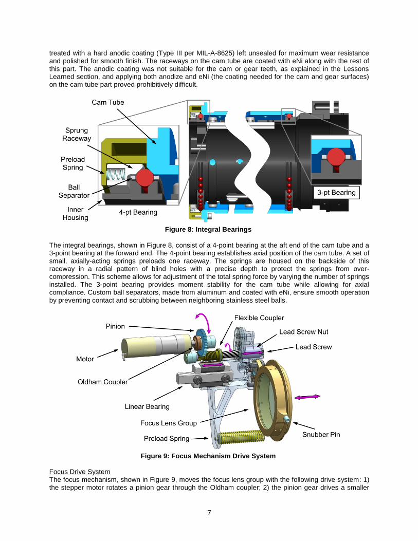
treated with a hard anodic coating (Type III per MIL-A-8625) left unsealed for maximum wear resistance and polished for smooth finish. The raceways on the cam tube are coated with eNi along with the rest of this part. The anodic coating was not suitable for the cam or gear teeth, as explained in the Lessons Learned section, and applying both anodize and eNi (the coating needed for the cam and gear surfaces) on the cam tube part proved prohibitively difficult.
Figure 8: Integral Bearings
The integral bearings, shown in Figure 8, consist of a 4-point bearing at the aft end of the cam tube and a 3-point bearing at the forward end. The 4-point bearing establishes axial position of the cam tube. A set of small, axially-acting springs preloads one raceway. The springs are housed on the backside of this raceway in a radial pattern of blind holes with a precise depth to protect the springs from over-compression. This scheme allows for adjustment of the total spring force by varying the number of springs installed. The 3-point bearing provides moment stability for the cam tube while allowing for axial compliance. Custom ball separators, made from aluminum and coated with eNi, ensure smooth operation by preventing contact and scrubbing between neighboring stainless steel balls.
Figure 9: Focus Mechanism Drive System
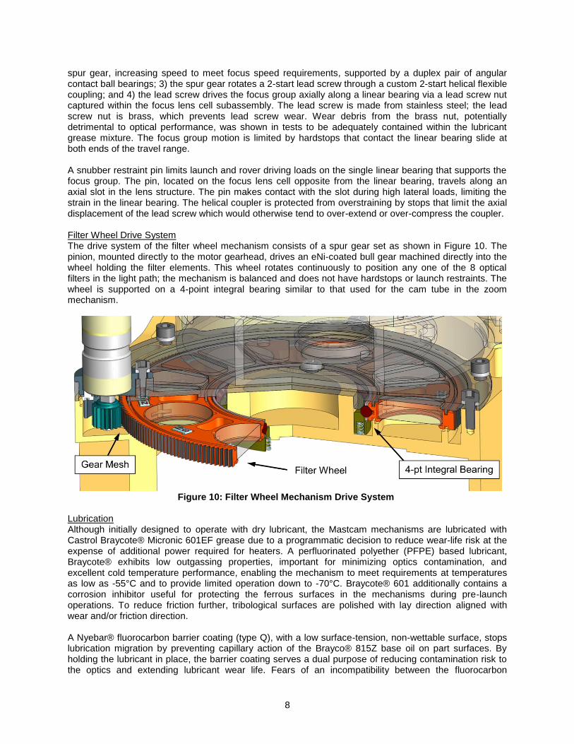
Focus Drive System The focus mechanism, shown in Figure 9, moves the focus lens group with the following drive system: 1) the stepper motor rotates a pinion gear through the Oldham coupler; 2) the pinion gear drives a smaller
8
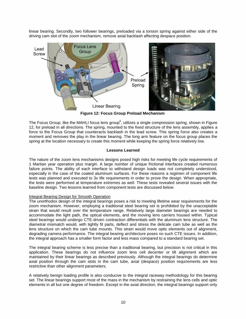
spur gear, increasing speed to meet focus speed requirements, supported by a duplex pair of angular contact ball bearings; 3) the spur gear rotates a 2-start lead screw through a custom 2-start helical flexible coupling; and 4) the lead screw drives the focus group axially along a linear bearing via a lead screw nut captured within the focus lens cell subassembly. The lead screw is made from stainless steel; the lead screw nut is brass, which prevents lead screw wear. Wear debris from the brass nut, potentially detrimental to optical performance, was shown in tests to be adequately contained within the lubricant grease mixture. The focus group motion is limited by hardstops that contact the linear bearing slide at both ends of the travel range. A snubber restraint pin limits launch and rover driving loads on the single linear bearing that supports the focus group. The pin, located on the focus lens cell opposite from the linear bearing, travels along an axial slot in the lens structure. The pin makes contact with the slot during high lateral loads, limiting the strain in the linear bearing. The helical coupler is protected from overstraining by stops that limit the axial displacement of the lead screw which would otherwise tend to over-extend or over-compress the coupler. Filter Wheel Drive System The drive system of the filter wheel mechanism consists of a spur gear set as shown in Figure 10. The pinion, mounted directly to the motor gearhead, drives an eNi-coated bull gear machined directly into the wheel holding the filter elements. This wheel rotates continuously to position any one of the 8 optical filters in the light path; the mechanism is balanced and does not have hardstops or launch restraints. The wheel is supported on a 4-point integral bearing similar to that used for the cam tube in the zoom mechanism.
Figure 10: Filter Wheel Mechanism Drive System
Lubrication Although initially designed to operate with dry lubricant, the Mastcam mechanisms are lubricated with Castrol Braycote® Micronic 601EF grease due to a programmatic decision to reduce wear-life risk at the expense of additional power required for heaters. A perfluorinated polyether (PFPE) based lubricant, Braycote® exhibits low outgassing properties, important for minimizing optics contamination, and excellent cold temperature performance, enabling the mechanism to meet requirements at temperatures as low as -55°C and to provide limited operation down to -70°C. Braycote® 601 additionally contains a corrosion inhibitor useful for protecting the ferrous surfaces in the mechanisms during pre-launch operations. To reduce friction further, tribological surfaces are polished with lay direction aligned with wear and/or friction direction. A Nyebar® fluorocarbon barrier coating (type Q), with a low surface-tension, non-wettable surface, stops lubrication migration by preventing capillary action of the Brayco® 815Z base oil on part surfaces. By holding the lubricant in place, the barrier coating serves a dual purpose of reducing contamination risk to the optics and extending lubricant wear life. Fears of an incompatibility between the fluorocarbon

9
Nyebar® barrier coating and the PFPE based Braycote® lubricant7,8,9
were allayed with a simple test that showed over 4 years of active repulsion of the lubricant by the barrier coating when applied with a specific process. Sputter-deposited Molybdenum Disulfide (MoS2) is used on the zoom mechanism launch restraints, in a belts-and-suspenders approach complementing the Braycote® grease, because the active surfaces in this interface undergo sliding wear (versus more benign rolling wear) and are subject to impact loads during launch. The MoS2 coating, fully compatible with Braycote®, is applied to both sides of this interface: the restraint ramp and the follower bearing pivot body. Motor Control The stepper motors are driven by MSSS-developed electronics at 2.2 volts and a 5 KHz PWM frequency at approximately 100 pulses per second. The motors are commanded to run a prescribed number of open-loop steps depending on the operational scenario. Position feedback is not required for operation. However, each mechanism provides position confirmation at one or more points along the range of travel via a latching Hall sensor and activating magnet pair(s). The magnet pairs, comprised of two magnets facing the Hall sensor with opposite poles, create a highly contrasting magnetic field and resulting sharp trigger threshold. In the zoom mechanism two trigger points signal when the cam followers are located in the launch restraints and again when halfway through the cam tube rotation. The focus mechanism has one trigger point along its range of travel. The filter wheel employs nine trigger points, one for each filter position and a ninth to index wheel rotation. If necessary, optical performance of the camera provides another means of feedback using analysis of image quality to determine positions of the focus, zoom, and filter wheel mechanisms. This simple open-loop control system has benefits but also revealed weaknesses discussed in the Lessons Learned section. Optics Mounting and Preloading Despace or axial position of each moving lens group is controlled by the actuating mechanism. The decenter and tilt alignment of moving groups are constrained by linear bearings. Preload devices counteract both axial backlash in the mechanisms and play in the linear bearings to minimize the effect that loads and gravity direction have on optical performance. Preload level is a compromise between accommodation of operational scenarios and tribological stress in wear surfaces. For example, wear-life duration is unacceptably short if the lens groups are preloaded to counteract all loads witnessed during rover driving scenarios.
Figure 11: Zoom Group Preload Mechanism (Zoom Group 3 Shown)
Two independent schemes, shown in Figure 11, are employed to preload each of the three tightly packaged, simultaneously moving zoom lens groups. First, in order to remove play in the linear bearing on which the zoom lens cells are mounted (i.e., the primary linear bearing), a compression spring pushes against a second linear slide, opposite from the primary linear slide. This secondary slide is not attached to the lens cell, but pulled along by a pin loosely fit into a hole on the lens cell. The force on the lens cell from the compression spring counteracts movement in tilt and decenter directions from play in the primary
10
linear bearing. Secondly, two follower bearings, preloaded via a torsion spring against either side of the driving cam slot of the zoom mechanism, remove axial backlash affecting despace position.
Figure 12: Focus Group Preload Mechanism
The Focus Group, like the MAHLI focus lens group
6, utilizes a single compression spring, shown in Figure
12, for preload in all directions. The spring, mounted to the fixed structure of the lens assembly, applies a force to the Focus Group that counteracts backlash in the lead screw. This spring force also creates a moment and removes the play in the linear bearing. The long arm feature on the focus group places the spring at the location necessary to create this moment while keeping the spring force relatively low.
Lessons Learned The nature of the zoom lens mechanisms designs posed high risks for meeting life cycle requirements of 1 Martian year operation plus margin. A large number of unique frictional interfaces created numerous failure points. The ability of each interface to withstand design loads was not completely understood, especially in the case of the coated aluminum surfaces. For these reasons a regimen of component life tests was planned and executed to 3x life requirements in order to prove the design. When appropriate, the tests were performed at temperature extremes as well. These tests revealed several issues with the baseline design. Two lessons learned from component tests are discussed below. Integral Bearing Design for Smooth Operation The unorthodox design of the integral bearings poses a risk to meeting lifetime wear requirements for the zoom mechanism. However, employing a traditional steel bearing set is prohibited by the unacceptable strain that would result over the temperature range. Relatively large diameter bearings are needed to accommodate the light path, the optical elements, and the moving lens carriers housed within. Typical steel bearings would undergo CTE-driven contraction differentials with the aluminum lens structure. The diametral mismatch would, with tightly fit parts, deflect and stress the delicate cam tube as well as the lens structure on which the cam tube mounts. This strain would move optic elements out of alignment, degrading camera performance. The integral bearing architecture poses no such CTE issues. In addition, the integral approach has a smaller form factor and less mass compared to a standard bearing set. The integral bearing scheme is less precise than a traditional bearing, but precision is not critical in this application. These bearings do not influence zoom lens cell decenter or tilt alignment which are maintained by their linear bearings as described previously. Although the integral bearings do determine axial position through the cam slots in the cam tube, axial (despace) position requirements are less restrictive than other alignment parameters. A relatively benign loading profile is also conducive to the integral raceway methodology for this bearing set. The linear bearings support most of the mass in the mechanism by restraining the lens cells and optic elements in all but one degree of freedom. Except in the axial direction, the integral bearings support only

11
the cam tube. When the integral bearings are loaded from acceleration in the axial direction, the complete set of balls supports the load, moderating contact stress. The aluminum raceways require a hard coating to protect the surface from breakdown and wear despite low loads. Aluminum is relatively soft and will not withstand even light friction or Hertzian contact stress. Making matters worse, direct contact between aluminum and Braycote® oil leads to a detrimental chemical reaction. Aluminum forms Lewis acids that catalytically decompose the PFPE oil
10, a process
known as the "brown sugar" effect, which causes premature failure of the lubricant. The Type III or "hard" anodic coating on the bearing raceways blocks this reaction and protects the aluminum surfaces. This coating is very hard, resists abrasion and can bear contact stress well. The coating is applied to a thickness that encompasses the depth of the contact-stress boundary. In the first round of component testing, problems arose for the integral bearings because of a polytetrafluoroethylene (PTFE, aka Teflon®) additive that was used as a lubricant in conjunction with the anodize coating (before wet lubricant was incorporated to the design). The additive was specified to be applied per AMS-2482 Type 1 (MIL-A-63576 Type I), a process believed to impregnate PTFE into the pores of the anodic coating. Initial component tests revealed that the PTFE material, evidently deposited in a layer on top of the anodize surface, would peel off in small flakes with the appearance of white dust or powder. This PTFE debris stuck together in clumps that jammed in the integral bearings and impeded rotation. Additionally, the debris posed an unacceptable contamination risk to the optics. Further investigation revealed that impregnating an anodic coating with PTFE is not physically possible because the long chain polymer molecules of PTFE are larger than the pores in an unsealed anodic coating
11.
Claims of PTFE impregnation of anodize with the various emulsion processes available at this time have not been substantiated to the authors' knowledge; a surface coating is the more likely result of any such process. Fortunately the adverse effects of the PTFE coating in this application were discovered using test hardware. The PTFE coating was eliminated early before the design had been finalized. Further testing, without the PTFE coating, revealed other complications with the integral bearings, however. Bearing rotation was uneven and unpredictable due to large variation in required driving torque (i.e., torque ripple). Investigation revealed that smooth operation was impeded by adjacent balls running into and scrubbing against each other in the full complement configuration baselined for these bearings. Several methods of relieving ball scrubbing were tested, including using ball separators, reduced ball quantities, balls of alternating sizes, and balls of differing materials. Ball separators clearly provided the smoothest operation of any design.
Figure 13: Unpolished and Polished Anodized Raceways
Further reduction of torque ripple was achieved by polishing the anodic coating. As applied, the anodic coating has an undulating, albeit smooth, "orange peel" surface finish as shown in Figure 13. After removing a small percentage of the coating thickness through the polishing process, most of the unevenness was eliminated, leaving a relatively flat, hard surface. Together with the ball separators, the

12
polished raceways resulted in consistent smooth operation for the integral bearings. Polishing also improved wear margins by reducing friction and lowering stress from uneven rolling. The final configuration of the integral bearings survived approximately 71,000 rotations during their individual component life test. Drive torques for the integral bearings at the end of this test were equal to or less than baseline torque measurements taken at the start of testing. Hard Coatings for Aluminum Alloys As demonstrated by the integral bearing testing, the Type III anodic coating is an excellent way to protect a relatively soft base material, such as aluminum. The anodic coating is extremely hard and strong, but it is brittle, a weakness that was made obvious in early tests of the cam/follower-bearing interface. Within the first 10% of the initial cam interface component life test duration, the cam surface exhibited complete failure. The anodic coating broke and chipped away, disintegrating under the load of the follower bearing until only bare aluminum remained on the cam surface; resulting debris finally seized the cam-follower bearing. At the time of initial component life testing, the baseline cam surface width was optimized for minimal mass of the cam tube part. The tube wall thickness and resulting cam surface width was relatively thin, enabling the follower bearing to contact the entire width of the cam, including the cam's edges as shown in Figure 14, as it rolled along the cam surface. Anodic coatings on aluminum, especially the MIL-A-8625, Type III anodic coatings, contain periodic flaws and cause embrittlement of the base metal, an effect which is aggravated near sharp corners or small radii. For example, anodic coatings 0.025 mm thick will regularly exhibit such problems on radii less than 0.76 mm; as the anodize thickness increases, this effect is exacerbated
12. The cam surface, having relatively sharp corners in the early design and coated with a
relatively thick anodize, abounded with embrittled material and corner flaws at its edges. Under pressure from the follower bearing, the coating chipped out and initiated failure of the cam surface during the component testing. It was surmised that similar problems would also exist in the small teeth of the gear integral to the cam tube, not yet tested, if finished with an anodic coating. Unlike the integral bearing tribulations, relatively little schedule remained for making design changes when the cam interface test failed. Here modifications had to fix the problem successfully with as few iterations as possible. Several tribology experts were consulted with this constraint in mind. With their advice, a three-pronged approach was adopted to mitigate program risk quickly. A multi-faceted line of attack was aimed at eradicating the problem even if one or more of the changes did not produce results.
Figure 14: Cam Geometry Changes (Cross-Sectional View)
The first part of the approach modified the geometry of the cam surface to improve coating coverage and reduce edge stress concentrations. The cam tube wall thickness was increased, as much as space in the converging design allowed, to more than double the original thickness. While the actual flat of the cam surface remained about the same size, the edge radii, made tangent to the cam surface and blended with the tube OD and ID, increased significantly. Figure 14 shows how the thicker cam tube wall provided a gradual transition to the cam flat compared with the initial design, a change anticipated to be more conducive to good coating results. The cam flat is toleranced to lie within the width of the follower bearing,

13
preventing contact with the edge of the bearing and resultant line contact-stress concentrations13
. The mass increase from the thicker-walled cam tube was compensated by adding more springs to the integral bearing sprung raceway, slightly increasing the preload spring force on the bearing. The second part of the approach reduced the torsion spring preload force in the cam-follower assembly. As a result, contact stresses in the cam surface were reduced considerably. A consequence of this change was loss of preload during most rover driving operations, due to the springs being overpowered by opposing mass accelerated during bumpy rides. But this capability was not considered critical; the change had no impact to the science objectives of the mission. The final piece in the recovery strategy replaced the anodic coating with electroless nickel (eNi). Electroless nickel was chosen from among many hard coating choices for its beneficial hardness and strength properties, because it could be applied uniformly over complex geometry in thicknesses that would encompass the depth of the Hertzian contact-stress fields, and also because it was perceived to be a fairly common and available coating. The eNi coating was specified per SAE AMS2404E (MIL-C-26074E) with a bakeout temperature that would not change the temper of the aluminum base material. Phosphorus content in the eNi was selected and specified for adequate strength properties considering contact-stress levels in the tribological interfaces. Mock-up parts were fabricated for the cam component life test per the new design approach. The testing produced successful results. Over 80,000 passes of the follower bearing over the cam were achieved with little wear, while drive torque remained unchanged from baseline measurements. By the time this component life test was conducted the programmatic switch to wet lubricant had also been made, which undoubtedly helped to a considerable degree. However, successful completion of the life tests proved to be only half the battle for the cam interface. Following the successful test results described, the design changes were made to the flight parts. Problems were encountered, however, in cam tube pathfinder parts during the eNi coating process. Applying a high-quality eNi coating to the cam tube proved extremely challenging. It was discovered that most coating vendors are set up to make aesthetic eNi coatings and are not prepared to finish complex geometry with a flaw-free, "tribological-grade" coating that minimizes the effects of friction. Even flaws not noticeable without magnification, such as those shown in Figure 15, can initiate deterioration or cause uneven operation and possible jamming of the small camera mechanisms if located on features like the cam or gear teeth, where surface finish is critical. Consequently, all parts were examined under at least 25x magnification for quality control before acceptance.
Figure 15: Successfully eNi-Coated Cam Tube and Common eNi Coating Flaws
Producing a flaw-free, high-quality eNi coating on a part with only one critical surface proved challenging, and often required several coating runs for success. Applying an acceptable coating on a cam tube possessing gear teeth, integral bearing raceways, and the three cam slots (all of which needed a high

14
quality finish) as shown in Figure 15 was much more difficult. Over a half-dozen vendors failed to provide an eNi coating of the necessary quality. Coating thickness, coating chemistry, part orientation, part surface contamination, coating bath contamination, bath agitation, and bath temperature required precise control; all were determining parameters for an acceptable coating. The attention to detail necessary to fine-tune these conditions demanded a continual focus from capable and patient engineers; it was not a task that could be handed to someone accustomed to the typical process used for a plumbing fixture, for example. These challenges were surmounted with a dedicated vendor. The parts used in the zoom lens assemblies were successfully coated with eNi and proven in over 1,300 zoom cycles executed during the lens assembly life test. Control Scheme Repercussions for Testing Stepper Motors An additional lesson learned about testing stepper motors used with position feedback systems such as Mastcam's emerged during mechanical lens assembly functional testing. The Mastcam motor control and feedback system employs a minimal approach: position knowledge is controlled by tracking step count commands sent by the electronics in the camera head. This simple control system has inherent benefits of low cost, low complexity and reduced vulnerability to failure, but it depends on reliable stepping of the motor when commanded. If position knowledge is lost due to stepping malfunction, camera operation becomes inefficient because time is consumed to reestablish mechanism position. Camera operation was sensitive to skipping more than 1% of commanded steps, a level of skipping typically not exceeded in a robust design. After integration, however, several Mastcam stepper motors exhibited a propensity to skip steps more often than this, even under nominal mechanism loading. An investigation was undertaken to isolate the root cause of the motor skipping. The motor, gearbox, and mechanism were all suspect, with emphasis placed on the mechanism because the motors had previously passed performance functional testing. This endeavor revealed an unplanned benefit of the Oldham coupling in the zoom and focus mechanism. The separable nature of this design lent itself to easy torque characterization of the fully assembled mechanisms without the motor in place. With a shaft inserted into the drive hole of the Oldham coupler, in place of the motor output shaft, a torque watch measured the mechanism actuation torque through the entire range of travel. The filter wheel mechanism, without this feature, was a simpler mechanism and could be evaluated easily by hand. Such characterization showed that the mechanisms were working nominally, requiring torques well within the motor limits. (Testing did show skipping sensitivity related to the pinion/gear mesh of the filter wheel mechanism, but this behavior was shown to not be the root cause of the motor skipping phenomenon.) Further testing of the motor revealed that the cause of the skipping behavior resided within the stepper motor or motor gearbox. Skipping incidence increased with higher torque loads but was clearly evident with no load as well. The behavior also did not appear to be a resonance issue dependant of inertial loading from the mechanism. Certain motors were proven to skip consistently up to 6% of steps while the unloaded output shaft was rotated. It was not clear if the issue originated in the motor itself or in the motor gearbox, but anecdotal evidence pointed towards the gearbox. The gears in the small diameter gearboxes were apparently very difficult to fabricate, causing delays in delivery. Worth noting is that duplicate spares of these motors leftover from the MER mission, obtained for performance comparison testing, did not exhibit the skipping behavior. The gears in these older motors were reportedly produced by a different vendor who was no longer available for the MSL effort. This behavior was not discovered until late in development because motor testing (both at the vendor pre-shipment and after receipt, pre-integration) did not measure or quantify missed steps. Torque capabilities were assessed without regard for the percentage of skipped steps, which are not easily noticed at levels of occurrence under 10%, when outside the context of the mechanisms. As a result, motors not suitable for the planned driving scheme were accepted and integrated with the camera mechanisms. The skipping issue was never completely characterized or solved due to schedule and budget constraints. Had the optical performance of zoom lens assemblies been better, the highest functioning motors may have been chosen for flight, as the skipping problems did not appear to compromise acceptable mission performance. Even when skipping to the degree described was observed, measured torque margins were robust. Furthermore, several motors had passed full MSL flight qualification testing,

15
including 2x life testing, by the time that the skipping issue arose. The motors ultimately used for the mission in the fixed focal length Mastcam and MAHLI cameras had not exhibited skipping behavior problems.
Conclusion The mechanical design for the Mastcam zoom lens presented a significant challenge of meeting stringent optical requirements in the severe Martian environment. This challenge led to non-standard solutions and unique designs for the mechanisms in the zoom lens. While the initial design failed in several areas, subsequent changes fixed these problems, enabling successful life testing of the fully integrated mechanism assembly. Reassessing baseline assumptions, when necessary, was a large part of this success. Examples include reducing preload spring forces, and resulting alignment expectations, and using wet lubricant with increased heater power. Fundamentals were important as well: careful bookkeeping of details in each frictional interface, consultation with tribology experts, and many hours spent in trial and error. Early component tests mitigated the impact of failures by uncovering numerous flaws when changes to the design were still possible. Additionally, these tests brought to light defects on a more discrete basis where they could be worked out individually rather than in the context of a complex system. Expeditious testing, however, posed its own hazards, as demonstrated by the stepper motor skipping phenomenon, a case where not all parameters were accounted for or understood. Although the zoom lens, left with little to no time for alignment adjustments, became a victim of the optical performance achievements of the fixed focal length lenses, its mechanisms were shown to be robust in the context of the MSL mission. Curiosity will not have the benefit of Zoom Lens Mastcam instruments while it explores Gale Crater and beyond during its quest on Mars. However, given time to optimize optical performance, the zoom lens and its mechanisms are poised to explore distant worlds on a future mission.
Acknowledgements The Mastcam mechanical lens assemblies were designed at MDA Information Systems, Inc., Space Division, in Pasadena (MDA) (www.MDAInformationSystems.com) under contract to Malin Space Science Systems (MSSS) (www.msss.com). Michael C. Malin (MSSS) is the Mastcam Principal Investigator, and the engineering work for the cameras was overseen by Mastcam Instrument Manager, Michael A. Ravine (MSSS). The authors give special thanks to Robert Bell and Rick Gelbard at Panavision for initial direction and support in the design effort; Jeffrey Lince of Aerospace Corp. for his expertise with MoS2 lubricants and assistance with tribological testing; Larry Lipp for his tribological knowledge and support; Yuichi Ikeuchi of IKO Nippon Thompson Co., LTD. for his knowledge of linear bearings; Keith Campbell at Castrol Industrial for his expertise on the Braycote® lubricants; Greg Levanas for help trouble-shooting motors; and Mark Balzer of JPL for his willingness to share mechanism knowledge and advice. Also, the authors thank the Mastcam review board members, and all other reviewers, for their time and help guiding the project. Finally, the authors thank Helen Aslanian, Jennifer Baker, Todd Cameron, Cole Corbin, Sean Dougherty, Rene Espinosa, Richard Fleischner, Richie Gov, Jay Harland, Ross Hironaka, Jacques Laramee, Brett Lindenfeld, Anthony Matthews, Todd McIntosh, Richard McKenzie, Jim Ostroff, William Reed, Chris Thayer, Dorian Valenzuela, and Tom Vanderslice of MDA for their tremendous sacrifice and work developing the Mastcam lens assemblies. The Mastcam project could not have been completed without the dedication and energy placed forth by them as well as many others at MDA and MSSS.

16
References
1. NASA/JPL "Mars Science Laboratory." Website, cited 2 January 2012 <http://mars.jpl.nasa.gov/msl>. 2. Malin Space Science Systems "Mars Science Laboratory (MSL) Mast Camera (Mastcam)." Website,
cited 2 January 2012 <http://www.msss.com/all_projects/msl-mastcam.php>. 3. NASA/JPL "MSL Science Corner: Mast Camera (Mastcam)." Website, cited 2 January 2012
<http://msl-scicorner.jpl.nasa.gov/Instruments/Mastcam/>. 4. Malin, M. C., M. A. Caplinger, K. S. Edgett, F. T. Ghaemi, M. A. Ravine, J. A. Schaffner, J. M. Baker,
J. D. Bardis, D. R. DiBiase, J. N. Maki, R. G. Willson, J. F. Bell III, W. E. Dietrich, L. J. Edwards, B. Hallet, K. E. Herkenhoff, E. Heydari, L. C. Kah, M. T. Lemmon, M. E. Minitti, T. S. Olson, T. J. Parker, S. K. Rowland, J. Schieber, R. J. Sullivan, D. Y. Sumner, P. C. Thomas, and R. A. Yingst. "The Mars Science Laboratory (MSL) Mast-Mounted Cameras (Mastcams) Flight Instruments." 41st Lunar and Planetary Science Conference, Abstract 1123 (2010).
5. Malin, M. C., J. F. Bell, J. Cameron, W. E. Dietrich, K. S. Edgett, B. Hallet, K.E.Herkenhoff, M. T. Lemmon, T. J. Parker, R. J. Sullivan, D. Y. Sumner, P. C. Thomas, E. E. Wohl, M.A.Ravine, M. A. Caplinger, and J. N. Maki. "The Mast Cameras and Mars Descent Imager (MARDI) for the 2009 Mars Science Laboratory." 36th Annual Lunar and Planetary Science Conference, Abstract 1214 (2005).
6. DiBiase, D. R. and J. Laramee. "Mars Hand Lens Imager: Lens Mechanical Design." Proceedings of the 2009 IEEE Aerospace Conference 7–14 March 2009, Big Sky, Montana (2009).
7. Jones, W. J. Jr. and M. J. Jansen. "Lubrication for Space Applications." NASA CR-2005-213424, p. 6. 8. Hilton, M. R. and P. D. Fleischauer. "Lubricants for High-Vacuum Applications." Aerospace Report
TR-0091(6945-03)-6 (SMC-TR-93-14) (15 March 1993), p. 37. 9. Stone, D. and P. Bessette. “Chapter 8: Liquid Lubricants.” In Space Vehicle Mechanisms: Elements
of Successful Design, edited by P. L. Conley, 185-213. New York: John Wiley & Sons, Inc., ©1998, p. 208.
10. Conley, P. L. and J. J. Bohner. "Experience with Synthetic Fluorinated Fluid Lubricants." Proceedings of the 24th Aerospace Mechanisms Symposium (1990), NASA CP-3062, pp. 213-230.
11. Stevenson, Milt Jr. Vice President and Chief Technology Officer, Anoplate Corporation, Syracuse, NY. Telephone interview, 7 February 2012.
12. MIL-A-8625F "Anodic Coatings for Aluminum and Aluminum Alloys." US Military Specification (10 September 1993), pp. 16-17.
13. Norton, Robert L. Machine Design: An Integrated Approach. New Jersey: Prentice-Hall Inc., ©1996, pp. 518-519, Chap. 7.