Embed Size (px)
Citation preview

Module #2
Transformation of stresses in 2-D
READING LISTDIETER: Ch. 2, Pages 20-27
Ch. 2 in McClintock and ArgonCh. 7 in Edelglass
HOMEWORKFrom Dieter2-1, 2-2, 2-5

Objectives
• Develop equations for transformation of axes.
• Apply equations to determine principal normal and shear stresses.
• Perform transformation graphically using Mohr’s circle.

Why bother?
• Engineering structures are subjected to many different types of applied loads:
– Tension
– Compression
– Bending
– Torsion
– Pressure
– Combinations of the above
• Complex states of normal and shear stress occur.
Why bother?
• These stress components vary in magnitude and direction relative to their location in the structure and the coordinate system with which they are related to.
• As engineers we need to make sure that the structures we design don’t fail as a result of the applied stresses.
• Thus, we need to identify locations where stresses are the most severe. Then we can do more detailed analysis if needed.

Principal Stresses and Axes
• Principal stresses:
– The most severe stresses (i.e., the maximum and minimum stresses) in a stress state.
• Principal axes:
– Directions in which principal stresses act.

The Stress Tensor
x
y
z
xx
xy
xz
zz
zyzx
yy
yx
yz
xy
zO
xx xy xz
yy yzij yx
zx z zzy
If we limit ourselves to two dimensions, we achieve a condition called plane stress.
This is where all stresses in one dimension become zero.[see the next page]

PLANE STRESSAll stresses are zero in one primary direction
(a) (c)(b)
xy
z
00
0 0 0
xx xy
xy yy
00 0 0
0
xx xz
zx zz
0 0 000
yy yz
zy zz
xy
z
xy
z
yx yy
xyxx
xz
xx
zz
zx
zz
yyyz
zy
xy yx xz zx yz zy

0 00 0
0 0 0 0 0 0
xx xy x x x y
xy yy x y y y
A*
x
yyy
xxxy
yx x x
x
yy y y x
x y

Transformation is accomplished via a force balance
Let’s first balance forces parallel to x′followed by y′

A*
y′
yy
xx
xy
yx
x x
x
yy y y x
x y
x x x y
A
AcosθAsinθ
x′
0 sin cos cos sin
cos cos sin sin
0 cos cos sin sin
cos sin sin cos
x x x yx xy
xx yy
y x y xy yx
xx yy
F A A A
A A
F A A A
A A
xy yx

2 2
2 2
cos sin 2 sin cos
( )sin cos (cos sin )
x x xx yy xy
x y yy xx xy
Solving for σx′x′ and τx′y′ yields:
THESE THREE BOXED EQUATIONS ARE KNOWN AS THE TRANSFORMATION OF STRESS EQUATIONS
2 2
2 2
cos sin 2 sin cos2 2 2 2
sin cos 2 sin cos
y y xx yy xy
y y xx yy xy
Since σy′y′ is 90° away from σx′x′, σy′y′ is:
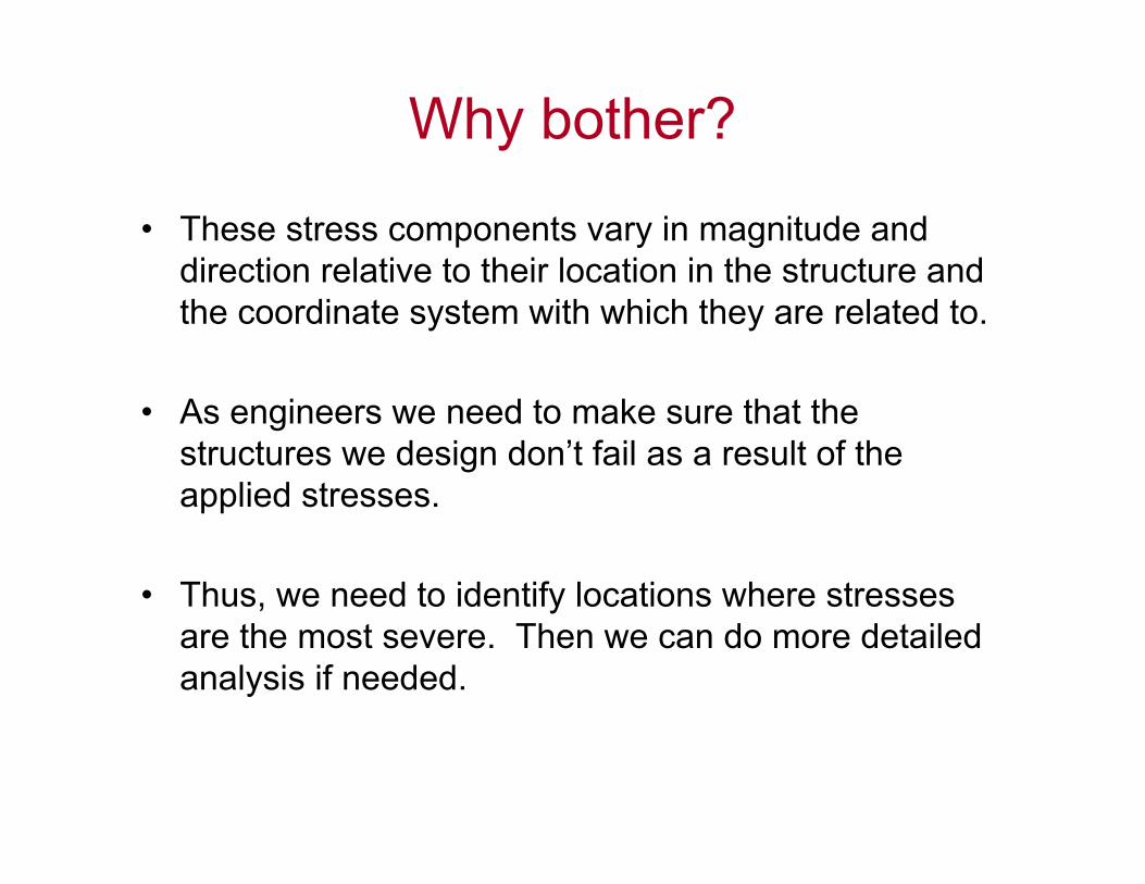
We can simplify the Transformation of Stress equations by invoking the double-angle identities
2
2
1cos 1 cos 22
1sin 1 cos 22
2sin cos sin 2

cos 2 sin 22 2
cos 2 sin 22 2
sin 2 cos 22
xx yy xx yyx x xy
xx yy xx yyy y xy
yy xxx y xy
They provide us with the stresses re-oriented to a new coordinate system
Transformation of Stress Equations(for plane strain)
00
0 0 0
x x x y
x y y y

cos2 sin22 2
cos2 sin22 2
xx yy xx yyxy
xx yyx x y yxx yy xx yy
xy
This quantity is invariant! It doesn’t change regardless of the coordinate system.
xx yyx x y y
An interesting observation

2 stress invariants for plane strain2 stress invariants for plane strain• I1 is the sum of the main diagonal of the
stress tensor.
• I2 is the sum of the principal minors.
1 xx yy x x y yI
2 22 xx yy xy x x y y x yI

0 20 40 60 80 100 120 140 160 180
-400
-200
0
200
400
600
800
1000max
max
x'y'
x'x'
Compression
S
tress
(MP
a)
(degrees)
xx = 800 MPayy = 200 MPaxy = -300 MPa
Tension
90o
45o
min
min
'
'
'
'
cos2 s
sin 2 c
i
os22
n 22 2
xx yy x
yy xxx
x yyx x x
y y
y
x

Principal planes
cos 2 sin 22 2
from previous viewgraph, normal stress is maximum (or minimum) when:
0 2sin 2 2 cos 22
Solving for yields the plane where maximum andminimum nor
xx yy xx yyx x xy
xx yyx xxy
dd
mal stress occur.
tan22
xyprincipal
xx yy
By definition this is also the plane where shear stress vanishes

Maximum in-plane shear stress
sin 2 cos 22
Shear stress is maximum/minimum when:
0 cos 2 2 sin 22
Solving for yields the plane of maximum/minimum shear stress
2tan2
An average norm
yy xxx y xy
x y xx yyxy
xx yyshear
xy
dd
al stress is superimposed on these planes
2xx yy
average

MAXIMUM & MINUMUM PRINCIPAL STRESSES FOR A 2-D STATE OF STRESS
2max 1 2
min 2
22
max
2 2
2
xx yy xx yyxy
xx yyxy

5 minute break

Mohr’s Circle for Stress• Developed in 1882; a graphical way to represent the
transformation of stress equations.
• Re-write the equations as:
' ' average
' '
cos 2 sin 22
sin 2 cos 22
xx yyx x xy
yy xxx y xy
' '
' '
cos 2 sin 22 2
sin 2 cos 22
xx yy xx yyx x xy
yy xxx y xy
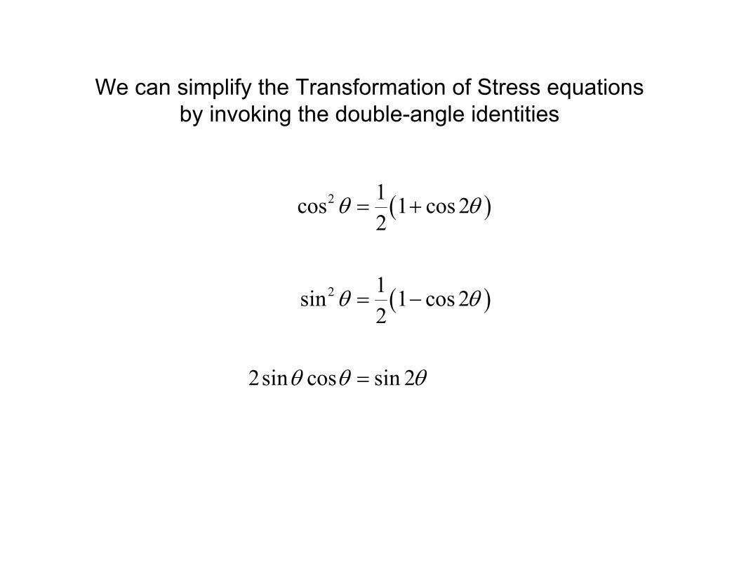
Mohr’s Circle
• Square both sides of each equation and add them together, which yields:
• Equation for a circle expressed in (,) coordinates with a center at (average, 0).
22 2 2
' ' average ' '
2 2 2' ' average ' '
2or
xx yyx x x y xy
x x x y R

• Recall the equation for a circle:
where h is the location of the center on the x axis (i.e., the center of the circle), and R is its radius.
• The center of Mohr’s circle lies at (average,0).
• The radius of Mohr’s circle is:
• max = 1 = average + R
• min = 2 = average - R
Mohr’s Circle – cont’d
2 2 2x h y R
average 2xx yy
22
max 32xx yy
xyR
The steps for construction are provided on the next 2
pages of the handout and/or in your mechanics
of materials book.

Steps in Construction of Mohr’s Circle1. Show the stresses xx, yy, and xy on a cube. Label the vertical plane V and
the horizontal plane H.
2. Write the coordinates of points V and H as V(xx, -xy) and H(yy, yx). A positive value for ij produces a CW moment about the center of the cube (i.e. CW rotation of the cube).
3. Draw the horizontal axis with the tensile normal stress to the right (i.e., positive) and the compressive normal stress to the left (i.e., negative). Draw the vertical axis with the clockwise (CW) direction of shear stress (i.e., positive) up and the counterclockwise (CCW) direction of rotation down.
4. Locate points V and H and join the points by drawing a line. Label the point where line VH intersects the horizontal axis as C, the center of the circle. The center has coordinates C(average, 0).
5. Draw Mohr’s circle with point C as the center and a radius, R of2
2max 32
xx yyxyR

Steps in Construction of Mohr’s Circle – cont’d6. The angle between lines CV and C1 is labeled 2 because the angles on
Mohr’s circle are double the actual angle between planes.
To determine the direction of rotation (i.e., the sign) we first record the direction in which we move from point V(σxx, -xy) to point (σ1, 0) on Mohr’s circle.
If the direction of rotation is CCW (i.e., towards the positive shear direction), then the sign of is positive. If the rotation is CW then the sign of is negative.
This is illustrated on the next viewgraph.

Intersection with the -axis is min=2
Intersection withthe -axis ismax = 1
max= 3
C(average, 0)
2
CW
CCW
V(xx, -xy)
H(yy, yx)
(1, )(2, )
• max = 1 = average + R
• min = 2 = average - R
xx
yy
xy
yx
VH
x
y
1
2
x
y
x′
y′

VERY IMPORTANT:
• Many engineering texts (and practicing engineers) construct Mohr’s circle with shear stress pointing downwards as is illustrated to the right. In this case, the rotations between the principal stress axes and the state of stress on the volume element will be opposite of that on Mohr’s circle.
• Be careful and know the system that your employer or the texts that you are referring to are using.
Intersection with the-axis is min=2
2
Coordinate is yy, xy
Coordinate is xx, - xy
Intersection with the -axis is max = 1
max= 3
Coordinate is average, 0
ProducesCW moment
Produces CCW moment
+
xx
yy
xy
yx
VH
x
y
1
2
x
y
x′
y′
2θ

Example Problem
1. Consider a point in a solid that is subjected to the following state of stress: σxx = 90 MPa; σyy = -50 MPa; τxy = -60 MPa.
a. Draw a free body diagram representing the stress state.
b. Determine the principal stresses, the maximum in-plane shear stress acting on the point, and the orientation of the principalplanes using Mohr’s circle.
c. Show the stresses no an appropriate diagram.

Example Problem - solution
a. Draw a free body diagram representing the stress state.
x
y
90 MPaxx
50 MPayy
60 MPaxy

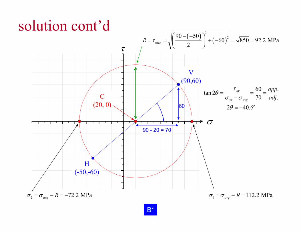
Example Problem – solution cont’db. Determine the principal stresses, the maximum in-plane
shear stress acting on the point, and the orientation of the principal planes using Mohr’s circle.
xx
yy
average
22
max
, 90,60
, 50, 60
90 50,0 ,0 20,0
2
90 5060 850 92.2
2
xy
xy
V
H
C
R

V(90,60)
H(-50,-60)
C(20, 0)
60tan 270
2 40.6
xy
xx avg
1 112.2 MPaavg R 2 72.2 MPaavg R
2
2max
90 5060 850 92.2 MPa
2R
60
90 - 20 = 70
A*
solution cont’d

H*
20
20
V(90,60)
H(-50,-60)
C(20, 0)
60 .tan 270 .
2 40.6
xy
xx avg
oppadj
1 112.2 MPaavg R 2 72.2 MPaavg R
2
2max
90 5060 850 92.2 MPa
2R
60
90 - 20 = 70
B*
solution cont’d

Example Problem - solution
c. Show the stresses on an appropriate diagram.
x
y
90 MPaxx
50 MPayy 60 MPaxy
20.3p
P
1 112.2 MPa
2 72.2 MPa
1
2
Note division of p by 2


![Mechanical Behavior Notes-2009c [Recovered] · 2018-10-08 · Mohr’s circle for strain READING LIST DIETER: Ch. 2, Pages 38-46 Pages 11-12 in Hosford Ch. 6 in Nye HOMEWORK From](https://img.dokumen.tips/doc/110x75/5f7fa5df7403b27ba75d8d8d/mechanical-behavior-notes-2009c-recovered-2018-10-08-mohras-circle-for-strain.jpg)