Embed Size (px)
Citation preview

© 2017 WIT Press, www.witpress.comISSN: 2046-0546 (paper format), ISSN: 2046-0554 (online), http://www.witpress.com/journalsDOI: 10.2495/CMEM-V5-N6-807-820
B. Berardinucci, et al., Int. J. Comp. Meth. and Exp. Meas., Vol. 5, No. 6 (2017) 807–820
MECHANICAL BEHAVIOR OF TIMBER–CONCRETE CONNECTIONS WITH INCLINED SCREWS
BEATRICE BERARDINUCCI, SIMONA DI NINO, AMEDEO GREGORI & MASSIMO FRAGIACOMO**Department of Civil, Architectural-Construction and Environmental Engineering, University of l’Aquila, Italy.
ABSTRACTTimber–concrete composite structures are often used as floor solutions in new and existing buildings to combine better acoustic separation and improved thermal insulation with increased stiffness and greater load-carrying capacity. The choice of a structurally effective yet cheap shear connection between the concrete topping and the timber joist is crucial to make the composite floor a viable solution that can compete with reinforced concrete and steel structures. The use of inclined screws is a possible option to maximize the slip modulus of the connection and, at the same time, keep the construction cost within acceptable values. In this paper, the results from an experimental and numerical investigation carried out on such a type of shear connection are reported. Push-out tests were carried out at the Laboratory of the Department of Civil, Building and Environmental Engineering of the University of L’Aquila. Each specimen consisted of a timber block connected to two concrete slabs by means of two 8 mm diameter screws per side produced by Rotho Blaas. A layer of OSB was interposed to reproduce the timber flooring often used as permanent formwork for the placement of the concrete slab in new floors or the existing timber flooring when strengthening existing timber structures. Two different screw lengths and interlayer thicknesses were investigated. For each configuration, 10 push-out specimens were tested. The results were statistically assessed by computing the mean slip moduli and the characteristic values of the shear strength. Numerical simulations were also carried out to investigate the dependency of the slip modulus upon the screw inclination and the interlayer flooring thickness.Keywords: connections, inclined screws, mechanical model, parametric analysis, Timber–concrete composite beams
1 INTRODUCTION
1.1 State of the art
Timber–concrete composite structures are increasingly employed as floor solutions. They consist of a timber element, connected to a concrete slab by means of shear connectors. These composite structural elements may be adopted in new buildings, where they combine better acoustic separation with improved thermal insulation, and in existing buildings, where strength and stiffness of the existing floor can be increased, and to the susceptibility to vibra-tions can be reduced. The choice of the connection system is crucial because it affects both structural performance and cost. Thus, special care must be given to the selection of stiff yet cheap connection systems. Shear connectors should be sufficiently stiff in order to ensure the composite action between timber and concrete elements. A simple solution is a line of screws, either self-tapping or into pre-drilled holes, vertically placed at a certain spacing along the beam. Screws have the advantage of being readily available off-the-shelf and easily installed. The recent availability on the market of self-tapping screws with continuous threads has given the opportunity to design a new geometrical configuration where screws are inclined at a certain angle in the vertical plane. Using screws inclined at 45° has been proved to result in higher values of stiffness and load-carrying capacities compared to the ‘traditional’ vertical configuration. Several experimental and numerical studies ([1–7]) have highlighted how the use of inclined screw provides an increase of the resistance and stiffness of the joints. This

808 B. Berardinucci, et al., Int. J. Comp. Meth. and Exp. Meas., Vol. 5, No. 6 (2017)
leads to a reduction of the number of the screws needed in a composite floor, under the same geometrical and loading conditions. In Ref. [1], Symons et al. developed some key concepts about mechanical properties of inclined screws. They present a model for the stiffness of inclined screws used as shear connectors in timber–concrete composite floors. Their model assumes the screw behaves as a beam on a two-dimensional elastic foundation. The model takes into account the inclination of the screw while the timber is represented by springs characterized from having different stiffness in the grain direction and in transversal direc-tions. No allowance for a possible interlayer is made.
In the present paper, an extension of the aforementioned model has been developed to allow for a possible interlayer. An experimental programme has been carried out on push-out specimens made of one timber element connected by four inclined screws to two concrete slabs. An OSB panel was interposed between the timber and the concrete to represent the permanent formwork used in new buildings, or the pre-existing timber flooring in the upgrade of an existing timber floor. The purpose of this study is to evaluate the influence of the OSB panel on the mechanical properties of the connection focusing on the stiffness of the inclined screws.
1.2 Motivations
To ensure a proper design, it is extremely important to characterize the mechanical behaviour of inclined screws. Specific rules provided by Eurocode 5 [8] only refer to timber-to-timber joints with metal fasteners placed perpendicularly to the shear plane and loaded perpendicu-larly to their axis. For joints made with dowel-type fasteners in timber to timber and wood based panel to timber connection, Eurocode 5 [8] provides some semi-empirical formulas for the prediction of the slip modulus per shear plane and per fastener:
.Kd
s m=
231 5ρ
(1)
K Ku s=2
3
where:Ks signifies the slip modulus of a connector for the serviceability limit state (N/mm);Ku signifies the slip modulus of a connector for the ultimate limit state (N/mm);ρm is the mean density of the timber element (kg/m3);d is the diameter of the fastener (mm);For timber to concrete connections, the value of Ks should be doubled up.Due to the lack of adequate method concerning the case of inclined screws, it [8] is recom-
mended that slip modulus (stiffness) and load carrying capacity of inclined screws are derived from experimental test according to Ref. [9].
2 EXPERIMENTAL PROGRAMME
2.1 Experimental setup
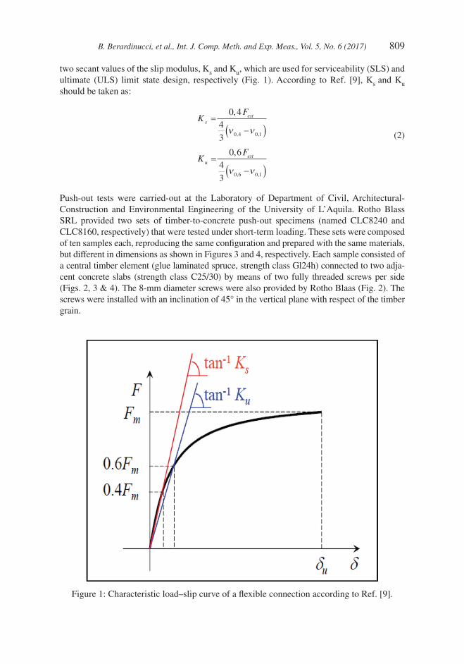
The typical load – slip (relative timber-to-concrete displacement) curve of a flexible connec-tion is characterized by a non-linear behaviour somehow difficult to be modelled. For this reason, some simplifications are made. The non-linear behaviour is accounted for by defining
B. Berardinucci, et al., Int. J. Comp. Meth. and Exp. Meas., Vol. 5, No. 6 (2017) 809
two secant values of the slip modulus, Ks and Ku, which are used for serviceability (SLS) and ultimate (ULS) limit state design, respectively (Fig. 1). According to Ref. [9], Ks and Ku should be taken as:
KF
sest
=
−( )
,
, ,
0 443 0 4 0 1ν ν
(2)
KF
uest
=
−( )
,
, ,
0 643 0 6 0 1ν ν
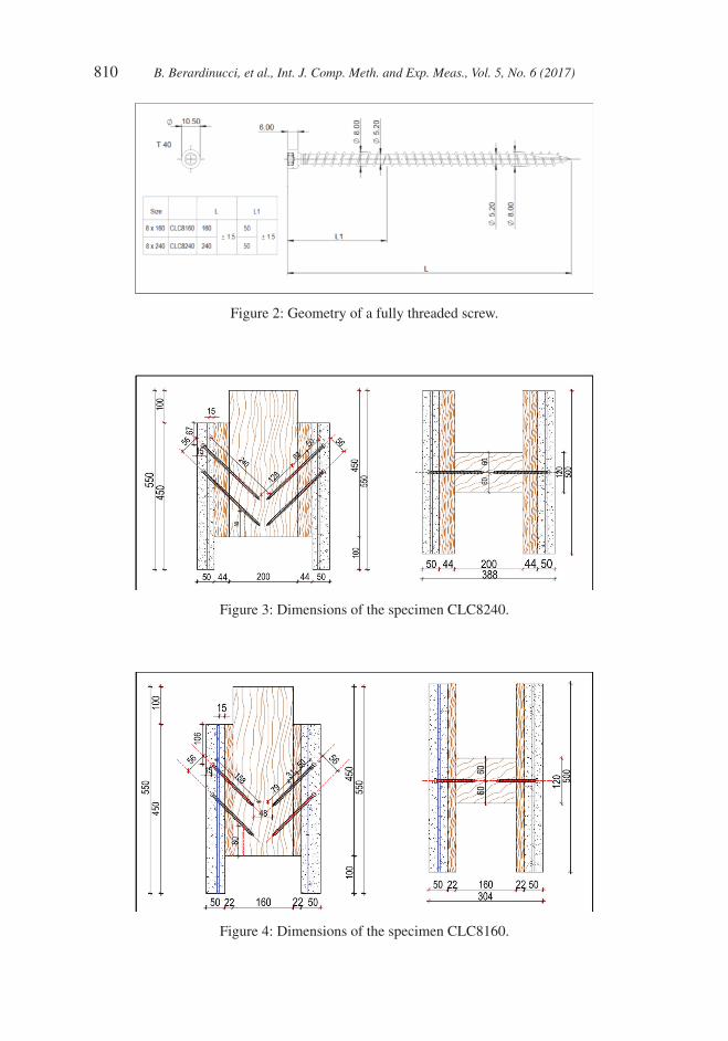
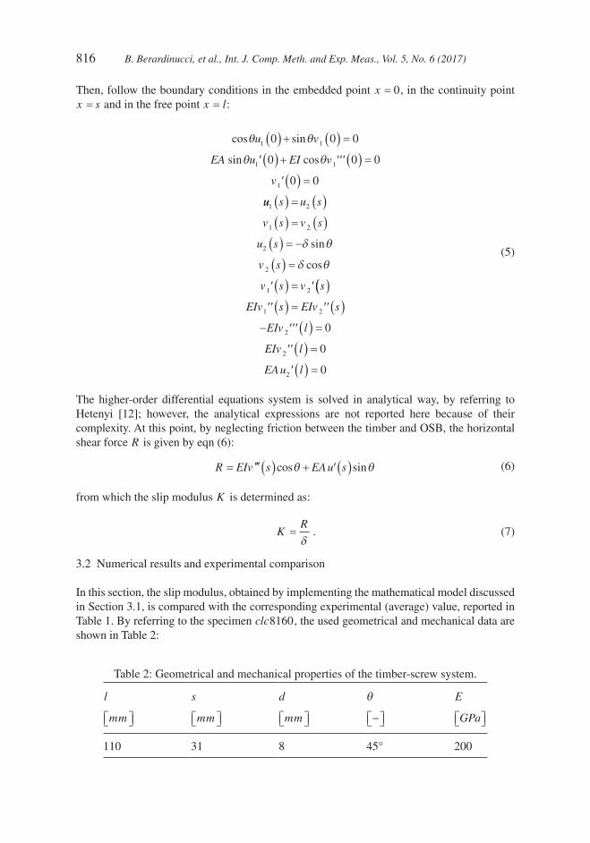
Push-out tests were carried-out at the Laboratory of Department of Civil, Architectural- Construction and Environmental Engineering of the University of L’Aquila. Rotho Blass SRL provided two sets of timber-to-concrete push-out specimens (named CLC8240 and CLC8160, respectively) that were tested under short-term loading. These sets were composed of ten samples each, reproducing the same configuration and prepared with the same materials, but different in dimensions as shown in Figures 3 and 4, respectively. Each sample consisted of a central timber element (glue laminated spruce, strength class Gl24h) connected to two adja-cent concrete slabs (strength class C25/30) by means of two fully threaded screws per side (Figs. 2, 3 & 4). The 8-mm diameter screws were also provided by Rotho Blaas (Fig. 2). The screws were installed with an inclination of 45° in the vertical plane with respect of the timber grain.
Figure 1: Characteristic load–slip curve of a flexible connection according to Ref. [9].
810 B. Berardinucci, et al., Int. J. Comp. Meth. and Exp. Meas., Vol. 5, No. 6 (2017)
Figure 2: Geometry of a fully threaded screw.
Figure 3: Dimensions of the specimen CLC8240.
Figure 4: Dimensions of the specimen CLC8160.

B. Berardinucci, et al., Int. J. Comp. Meth. and Exp. Meas., Vol. 5, No. 6 (2017) 811
In order to reproduce the permanent formwork usually adopted in new building projects or the pre-existing timber floor frequently found in refurbishment projects, an OSB panel was interposed between the timber element and the concrete slab. The thickness of the OSB panel was 20 mm in CLC8160 specimens and 44 mm in CLC8240 specimens.
According to Ref. [9], push-out tests were performed on specimens to record the load-slip curves. Subsequently, statistics was used to estimate the mean slip moduli and the characteristic values of the shear strength.
To record the relative vertical displacement between the concrete slabs and the timber element in the push-out specimens, four displacement piezoelectric transducers were fixed at the four corner of the sample and the average of four measurements was considered.
To replicate the real case of a composite floor, where the timber element cannot separate from the concrete slab due to the effect of the gravity loads, tension rods were used in the upper and lower part of each sample to prevent elements separation during the test (Fig. 5).
Figure 5: Photo of a push-out specimen during the test.

812 B. Berardinucci, et al., Int. J. Comp. Meth. and Exp. Meas., Vol. 5, No. 6 (2017)
Using specimens with a concrete slab per side provided the needed symmetry to have a stable configuration of the samples during the push-out test (Fig. 6). Specimens were placed under the loading machine and the push-out test procedure was followed in accordance to the standard [9]: the load was increased to 0,4 Fest (with Fest maximum estimated load, estimated on the basis of past experience, or based on preliminary tests) and maintained for 30 s, then reduced to 0,1 Fest and also maintained for 30 s, thereafter the load was increased until the deformation of 15 mm was achieved.
2.2 Results
A load–slip curve was obtained from each of the ten specimens. Curves related to set CLC8240 are presented in Figure 7 and curves related to specimens CLC8160 are shown in Figure 8. The peak value of the curves represents the ultimate load; stiffness was calculated as the secant value of the slip modulus at the 40% and at the 60% of the estimated load.
Then, in accordance to standard [10], the characteristic value of the load carrying capacity per specimen was calculated taking into account that values are logarithmically normally distributed. At the same time, also the mean value of stiffness per specimen was calculated, taking into account that values are normally distributed. The characteristic value of the load carrying capacity and mean value of the stiffness K per each of the two specimen types are shown in Table 1: Ku and Ks are used for ULS and SLS design, respectively.
During the push-out tests, no cracks appeared in the concrete slabs, but vertical displace-ment at the interface between timber and concrete slab resulted in timber crushing, as shown in Figure 9. The failure mode remained fairly constant in all the cases, involving the timber element and the screws. Two combined failure modes were observed: the ultimate load- carrying capacity was reached with the timber element yielding plastically along the screw meanwhile screws exceeded their withdrawal capacity. In all cases, no plastic hinges were noticed along the screw length.
Figure 6: Assembly procedure of a sample.

B. Berardinucci, et al., Int. J. Comp. Meth. and Exp. Meas., Vol. 5, No. 6 (2017) 813
3 MECHANICAL MODEL FOR STIFFNESS PREDICTIONScrews inclined in the direction of slip have been shown to provide a higher stiffness (slip modulus) than vertically placed screws. This section describes a theoretical model, inspirited to Ref. [1], for calculating the stiffness (slip modulus) of inclined screws when used as shear connectors in timber–concrete composite floors or beams. The model considers the initial response of the connection, before any inelastic behaviour, and assumes that the screw
Figure 7: Experimental load-slip curves for specimens CLC8240.
Figure 8: Experimental load-slip curves for specimens CLC8160.

814 B. Berardinucci, et al., Int. J. Comp. Meth. and Exp. Meas., Vol. 5, No. 6 (2017)
behaves as a beam on a two-dimensional elastic foundation. Unlike [1] where concrete and timber are in direct contact, this paper takes also into account an OSB sheathing inserted between the concrete and the timber, as shown in Figures 3 and 4.
A comparison with some experimental results is provided and parametric studies are performed in order to optimize the system stiffness.
3.1 Mathematical model
Figure 10 represents the model of a screw inclined at an angle θ to the vertical. The screw is modelled as a beam having flexural rigidity EI and axial stiffness EA . Since concrete is typ-ically around four times stiffer than structural timber and the substantial head of a typical coach screw is expected to provide significant restraint, it is assumed that the upper portion of the screw embedded in concrete is rigidly held. Therefore, it is only necessary to model the length l of the screw, of which a part s is embedded in OSB and another part (l s− ) is embed-ded in timber. The timber is modelled by a set of independent springs in the horizontal
Table 1: Calculation of characteristic and mean values.
Specimen CLC8160
Fu Ku K s
KN N mm/
N mm/
14,5 14699 15210
Specimen CLC8240
Fu Ku K s
KN N mm/
N mm/
9,0 11129 11213
Figure 9: Failure modes.

B. Berardinucci, et al., Int. J. Comp. Meth. and Exp. Meas., Vol. 5, No. 6 (2017) 815
(parallel to the grain) and vertical (transverse to the grain) directions; the stiffnesses of these springs, per unit length, are kp and kt , respectively. Due to its low mechanical properties, as first approximation, the OSB layer has been modelled as an empty gap of thickness s between the concrete slab and the timber element. A horizontal slip displacement δ is applied at the interface between timber and OSB. By referring to the system x y,( ) in Figure 10, the displace-ment field of the beam is described by the tangent and normal components, u x v xh h( ) ( ), , where the subscript h =1 2, is used to distinguish the screw lengths respectively without and with springs. By assuming displacement and strains to be small so that linear kinematics can be adopted, the field equations are found to be:
− ( ) =
( ) =
( ) ( ) + ( ) ( ) −
EAu x
EIv x
k u x k v x EAu xxx xy
1
1
2 2 2
0
0
’’
’’’’
’’θ θ (( ) =
( ) ( ) + ( ) ( ) + ( ) =
∈( )0
0
0
2 2 2k u x k v x EIv x
x l
yx yyθ θ’’’’
, (3)
with:
k kt kp
k kp kt
k
xx
yy
xy
θ θ θ θ θ
θ θ θ
( ) = +( )
( ) = +( )
cos sin cos sin
cos sin3 3
θθ θ θ θ θ θ( ) = ( ) = − +( )k kp kpyx cos sin cos sin
. (4)
Figure 10: Model of an inclined screw on elastic foundation.
816 B. Berardinucci, et al., Int. J. Comp. Meth. and Exp. Meas., Vol. 5, No. 6 (2017)
Then, follow the boundary conditions in the embedded point x = 0, in the continuity point x s= and in the free point x l= :
cos sin
sin cos
θ θ
θ θ
u v
EA u EI v
v
1 1
1 1
1
0 0 0
0 0 0
0 0
( ) + ( ) =
( ) + ( ) =
( ) =
′ ′′′
′
uu s u s
v s v s
u s
v s
v s v s
1 2
1 2
2
2
1 2
( ) = ( )
( ) = ( )
( ) = −
( ) =
( ) =
δ θ
δ θ
sin
cos
′ ′(( )
( ) = ( )
− ( ) =
( ) =
( ) =
EIv s EIv s
EIv l
EIv l
EAu l
1 2
2
2
2
0
0
0
′′ ′′
′′′
′′
′
(5)
The higher-order differential equations system is solved in analytical way, by referring to Hetenyi [12]; however, the analytical expressions are not reported here because of their complexity. At this point, by neglecting friction between the timber and OSB, the horizontal shear force R is given by eqn (6):
R EIv s EAu s= ( ) + ( )′′′ cos sinθ θ′ (6)
from which the slip modulus K is determined as:
KR
=
δ
. (7)
3.2 Numerical results and experimental comparison
In this section, the slip modulus, obtained by implementing the mathematical model discussed in Section 3.1, is compared with the corresponding experimental (average) value, reported in Table 1. By referring to the specimen clc8160, the used geometrical and mechanical data are shown in Table 2:
Table 2: Geometrical and mechanical properties of the timber-screw system.
l
mm
s
mm
d
mm
θ
−
E
GPa
110 31 8 45° 200

B. Berardinucci, et al., Int. J. Comp. Meth. and Exp. Meas., Vol. 5, No. 6 (2017) 817
The values kp MPa=1300 e kt MPa= 650 , with β = =kp kt/ .0 5, were taken at first from [1], where the measurements of timber foundation stiffness are reported for differ-ent timber species. The experimental comparison showed that the analytical slip modulus K results three times as large as the experimental one, probably due to the margin of error in defining the stiffness springs, as can be noted also in Ref. [1]. Therefore, the mechanical model can be used to calibrate the springs stiffness: for a fixed ratio β = 0 3. , the slip modulus is calculated for different values of the horizontal springs stiffness, see Figure 11:
To fit the experimental results, the springs stiffness value should be assumed as kp MPa= 400 .
3.3 Parametric study
The slip modulus depends in a non-linear way by the geometric and mechanical properties of the timber-screw system. Depending on that, the stiffness K may increase or decrease as shown in Figure 12:
The following observations can be made:
• by incrementing the angle inclination of the screw, the slip modulus increases until reaching the maximum value for θ ≅ °50 , after that it decreases;
Figure 11: Slip modulus depending upon the springs stiffness.

818 B. Berardinucci, et al., Int. J. Comp. Meth. and Exp. Meas., Vol. 5, No. 6 (2017)
• for increasing values of the ratio β , the slip modulus increases, the system has therefore a greater stiffness when the wood is characterized by similar mechanical proprieties in the parallel and transverse directions to the grain;
• by incrementing the ratio between diameter and length of the screw, also the slip modulus increases;
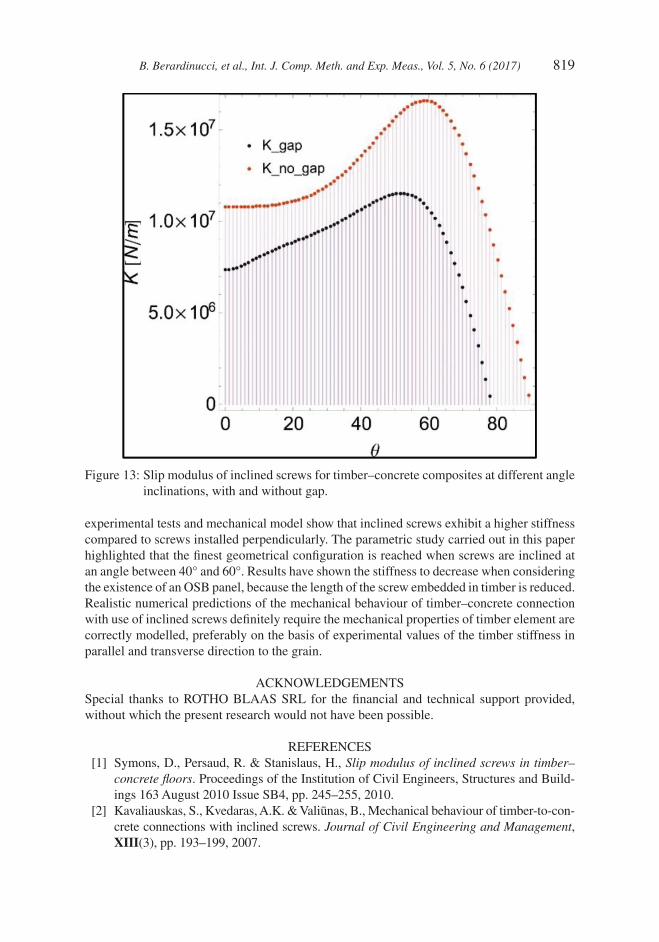
• finally, for increasing values of the OSB thickness with respect to the screw length, the slip modulus decreases. For example, in the search for the optimum inclination angle of the screws, in Figure 13 it is shown the different behaviour with or without gap.
4 CONCLUSIONSIn this paper a mechanical model for calculating the slip modulus of inclined screw was proposed. To ensure proper design is extremely important to characterize the mechanical behaviour of inclined screws, specifically the slip modulus Ku of a connection at ultimate limit state (important to evaluate the internal stresses in the composite section) and the slip modulus Ks at the serviceability limit state (relevant for evaluating instantaneous deflections). Both
Figure 12: Parametric study of the slip modulus depending upon: (a) angle of screw inclination θ ; (b) ratio between the stiffness of the transverse kt and parallel kp springs; (c) ratio between diameter d and length l of the screw; (d) ratio between the OSB thickness projected at 45° s and the screw length l.
B. Berardinucci, et al., Int. J. Comp. Meth. and Exp. Meas., Vol. 5, No. 6 (2017) 819
experimental tests and mechanical model show that inclined screws exhibit a higher stiffness compared to screws installed perpendicularly. The parametric study carried out in this paper highlighted that the finest geometrical configuration is reached when screws are inclined at an angle between 40° and 60°. Results have shown the stiffness to decrease when considering the existence of an OSB panel, because the length of the screw embedded in timber is reduced. Realistic numerical predictions of the mechanical behaviour of timber–concrete connection with use of inclined screws definitely require the mechanical properties of timber element are correctly modelled, preferably on the basis of experimental values of the timber stiffness in parallel and transverse direction to the grain.
ACKNOWLEDGEMENTSSpecial thanks to ROTHO BLAAS SRL for the financial and technical support provided, without which the present research would not have been possible.
REFERENCES [1] Symons, D., Persaud, R. & Stanislaus, H., Slip modulus of inclined screws in timber–
concrete floors. Proceedings of the Institution of Civil Engineers, Structures and Build-ings 163 August 2010 Issue SB4, pp. 245–255, 2010.
[2] Kavaliauskas, S., Kvedaras, A.K. & Valiūnas, B., Mechanical behaviour of timber-to-con-crete connections with inclined screws. Journal of Civil Engineering and Management, XIII(3), pp. 193–199, 2007.
Figure 13: Slip modulus of inclined screws for timber–concrete composites at different angle inclinations, with and without gap.
820 B. Berardinucci, et al., Int. J. Comp. Meth. and Exp. Meas., Vol. 5, No. 6 (2017)
[3] Tomasi, R., Crosatti, A. & Piazza, M., Theoretical and experimental analysis of timber-to-timber joints connected with inclined screws. Construction and Building Materials, 24, pp. 1560–1571, 2010.https://doi.org/10.1016/j.conbuildmat.2010.03.007
[4] Fragiacomo, M. & Lukaszewska, E., Development of prefabricated timber-concrete composite floor systems. Structures and Buildings, 164(2), pp. 117–129, 2011.https://doi.org/10.1680/stbu.10.00010
[5] Bejtka, I. & Blaß, H.J., Joints with inclined screws. Proceedings from meeting thirty-five of the international council for building research studies and documentation, CIB, Working Commission W18 – Timber Structure, Kyoto, Japan, 2002.
[6] Bejtka, I. & Blaß, H.J., Screws with continuous threads in timber connections. RILEM, Proceedings PRO 22, Stuttgartl, 2001.
[7] Ceccotti, A., Fragiacomo, M. & Gutkowski, R.M., On the design of timber–concrete composite beams according to the new versions of Eurocode 5. 35th Meeting of the Working Commission W18–Timber Structures, International Council for Research and Innovation in Building and Construction, Kyoto, Japan, 2002, pp. 10–24.
[8] EN 1995-1-1, Eurocode 5: Design of timber structures - Part 1-1: General - Common rules and rules for buildings. CEN, 2004.
[9] UNI EN 26891, Timber structure – Joints made with mechanical fasteners – General principles for the determination of strength and deformation characteristic. CEN, 1991.
[10] BS EN 14358:2016, Timber structures – Calculation and verification of characteristic values. CEN, 2016.
[11] EN 13183-1, Moisture content of a piece of sawn timber – Determination by oven dry method. CEN, 2002.
[12] Hetényi, M., Beams on elastic foundation: theory with applications in the fields of civil and mechanical engineering. University of Michigan, 1971.