Embed Size (px)
Citation preview
1. IntroductionSnO2 is an oxide semiconductor with many applica-tions in the areas of sensors [1, 2] and optoelec-tronic devices [3, 4]. The properties of SnO2 in var-ious forms such as nanoparticles [5], nanowires [6],nanobelts [7] and other one-dimensional nanostruc-tures have been extensively studied. In comparisonwith solid one-dimensional nanomaterials, nan-otubes gain the advantages in practical applicationsto catalysts and gas sensors, owing to their higher sur-face-to-volume ratio. Generally, the conventionalmethods for preparing SnO2 nanotubes by self-assembly [8] and templates directed process [9]often suffer from strict synthesis conditions or tediousprocedures. Electrospinning has been considered asa simple and efficient method for fabricating nano -fibers including organic and inorganic materials.
However, templates and the co-electrospinningtechnique [10] had to be used for forming inorganicnanotubes. Herein, one-step method for the fabrica-tion of SnO2 hollow nanofibers by directly anneal-ing electrospun composite nanofibers was proposedin this work. Though Cheng et al. and Li’s grouphave reported the fabrication of hollow TiO2 nano -fibers [11] and porous SnO2 nanofibers [12] by thesimilar technique, respectively; there has been noreport about the detailed analysis on the formationmechanism and the growth behavior of nanograinson the nanofiber surface. Generally, the formationmechanism of hollow nanofibers which were fabri-cated via the electrospinning process, followed byheat treatment is attributed to the decomposition ofsacrificial template of organic polymer at the hightemperature.
169
Formation mechanism of porous hollow SnO2 nanofibersprepared by one-step electrospinningX. Xia1,2, X. J. Dong1, Q. F. Wei1*, Y. B. Cai1, K. Y. Lu3
1Key Laboratory of Eco-textiles, Jiangnan University, 214122 Wuxi, People’s Republic of China2Xinjiang University, Xinjiang, 830046 Wulumuqi, People’s Republic of China3State Key Laboratory of Food Science and Techology, 214122 Wuxi, People’s Republic of China
Received 27 June 2011; accepted in revised form 16 September 2011
Abstract. The present study investigates the formation mechanism of hollow SnO2 nanofibers and the form of nanograingrowth in nanofibers. SnO2 hollow nanofibers were fabricated by directly annealing electrospun polyvinylpyrrolidone(PVP)/Sn precursor composite nanofibers. In this approach, an appropriate proportion of PVP/Sn precursor with co-sol-vents established a system to form core/shell PVP/Sn precursor structure, and then PVP was decomposed quickly whichacted as sacrificial template to keep fibrous structure and there existed a Sn precursor/SnO2 concentration gradient to formhollow SnO2 nanofibers due to the Kirkendall effect and surface diffusion during the calcination process. This deductionwas also confirmed by experimental observations using transmission electron microscopy. The study suggested that surfacediffusion and lattice diffusion were both driving force for nanograin growth on the surface of SnO2 nanofibers. As support-ing evidence, the tetragonal rutile SnO2 hollow nanofibers were also characterized by X-ray diffraction, scanning electronmicroscopy and Brunauer–Emmett–Teller analysis.
Keywords: nanomaterials, SnO2, hollow nanofiber, electrospinning, Kirkendall effect
eXPRESS Polymer Letters Vol.6, No.2 (2012) 169–176Available online at www.expresspolymlett.comDOI: 10.3144/expresspolymlett.2012.18
*Corresponding author, e-mail: [email protected]© BME-PT

In this work, a systematic investigation into thestructures of as-spun nanofiber, the effect of calci-nation and crystallite growth was conducted forunderstanding the formation mechanism of SnO2hollow nanofibers. In addition, the growth kineticsSnO2 nanograin in individual nanofiber was alsoproposed.
2. Experimental2.1. Preparation of porous hollow SnO2
nanofibersStannic chloride pentahydrate (SnCl4·5H2O), ethanoland N,N-dimethylformamide (DMF) were pur-chased from Sinopharm Chemical Reagents Co.,Shanghai, China. Polyvinylpyrrolidone (PVP, Mw =1300 000 g·mol–1) was supplied by Qi Fuqin Mate-rials Technology Co., LTD. Shanghai, China. Trans-parent spinning solution was prepared by adding 3 gof SnCl4·5H2O into 10 wt% PVP in ethanol/DMFsolvent mixture (weight ratio 1:1), and the weightratio of PVP and SnCl4·5H2O was also 1:1, followedby magnetic stirring at ambient temperature. Subse-quently, the solution was electrospun from thestainless steel needle with an electrostatic voltageof 18 kV, and formed a fibrous mat on a collector ofaluminum foil. The distance between the needle andcollector was 22 cm. The electrospun fibers werethen calcinated at 600°C for 3 hrs with a heatingrate of 0.5°C/min.
2.2. Structural observationsThe structures of the electrospun nanofibers wereobserved by a scanning electron microscope (SEM;Hitachi S-4800, Japan) and a high-resolution trans-
mission electron microscope (TEM; JEOL-2100,Japan). The electrospinning specimens were sputtercoated with gold before SEM observation, while theSnO2 nanofibers were examined without any fur-ther treatment. For TEM observation, the electro-spun composited nanofibers were directly collectedon the copper grids for about 30 seconds duringelectrospinning, while the SnO2 nanofibers weredispersed ultrasonically in ethanol, and then trans-ferred onto copper grids before TEM observation.
2.3. XRD and TGA analysesThe crystal structure analysis was performed on D8Advance X-ray diffraction (Bruker AXS, Germany),over the 2! range of 10–80º. Thermogravimetricstudies were carried out using an SDT 851 thermalanalyzer system (Mettler, Germany) at a heatingrate of 10°C/min.
2.4. Surface area measurementThe porosity and specific surface areas of the elec-trospun fibers were measured by N2 adsorption-desorption isotherm at 77 K with a MicromeriticsNOVA2000e apparatus (Quantachrome, America).
3. Results and discussion3.1. Structure observationsFigure 1 demonstrates the morphologies of the elec-trospun nanofibers before and after calcination at600°C. The as-spun PVP/SnO2 nanofibers have avariable diameter ranged between 50 and 300 nmand form a self-supporting network, as shown inFigure 1a. The TEM image clearly reveals the core-shell structure with clear boundary of a phase sepa-
Xia et al. – eXPRESS Polymer Letters Vol.6, No.2 (2012) 169–176
170
Figure 1. SEM images of (a) as- spun PVP/SnO2 nanofibers (b) porous hollow SnO2 nanofibers after calcination at 600°C

ration between PVP and Sn precursor, as presentedin Figure 2.Figure 1b shows the image of SnO2 nanofibersobtained by the calcination treatment of as-spuncore-shell PVP/SnO2 nanofibers. It can be clearlyseen that these fibers have a tubular structure withdense shells, which consist of nanograins of approxi-mately 17 nm in diameter, as revealed in Figure 1b.Besides SnO2 nanofibers have a relatively uniformdiameter, the outer diameter of the hollow fibers isdecreased compared to that of the as-spun PVP/SnO2 fibers shown in Figure 1a.
3.2. Formation of porous hollow SnO2nanofibers
The forming process of hollow SnO2 nanofibersexperiences 5 stages during electrospinning and
calcination. Based on the TEM observations com-bined TGA/DTGA analysis, the formation processof SnO2 nanofibrous structures can be traced. At theinitial stage during electrospinning, the core-shellfibers are fabricated via single capillary electrospin-ning from homogeneous polymer-sol-double sol-vents system due to solvent evaporation and rapidphase separation [13]. Various factors may havestrong influences on the morphology of the electro-spun fibers due to the complexity of hydrolysis andcondensation reactions during the gelation of sol aswell as the process of fiber formation. The hydroly-sis reaction of SnCl4 in water is schematically illus-trated in Figure 3. In this work, excessive ethanolwas applied to prepare Sn precursor but insufficientH2O was used to make it partially hydrolyzed. Thus,the polymerization and polycondensation reactionsof tin dioxide could be limited to a very low level.Furthermore, a kind of more volatile solvent ethanolevaporates rapidly at the edge of the fiber and acontrary concentration gradient of ethanol and DMFalong the radial direction of the fiber will be formedduring electrospinning. Especially, ethanol, the50% weight ratio of solvents, which was used forpreparation tin alkoxide, on the surface of the fibersis too little to form large solvent-rich regions duringthe phase separation because of the rapid evapora-tion. The high molecular weight PVP and high con-centration solution contribute to retain less ethanolto form porous surface as well. So the smooth andcompact surface without any porous structures canbe observation by TEM, as revealed in Figure 2. Atthe same time, Sn precursor in nature has a verymuch higher solubility in ethanol than in PVP [14].So, it would diffuse from the surface to the core ofthe fiber. As a result, Sn precursor tends to congre-
Xia et al. – eXPRESS Polymer Letters Vol.6, No.2 (2012) 169–176
171
Figure 2. TEM images of as-spun PVP/SnO2 nanofibers atroom temperature
Figure 3. Schematic illustration of the hydrolytic–polymeric reaction of SnCl4·5H2O. Tin, blue; oxygen, red; carbon, pur-ple; hydrogen, white; chlorine, brown.
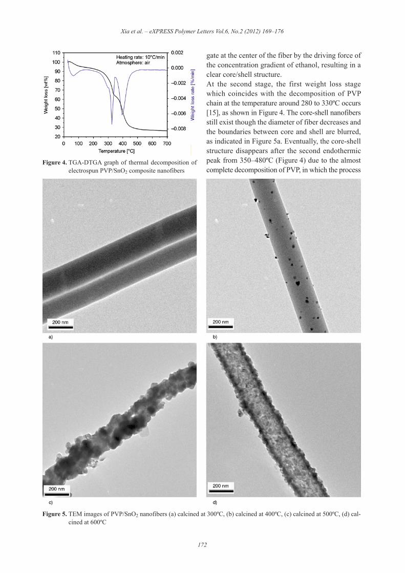
gate at the center of the fiber by the driving force ofthe concentration gradient of ethanol, resulting in aclear core/shell structure.At the second stage, the first weight loss stagewhich coincides with the decomposition of PVPchain at the temperature around 280 to 330ºC occurs[15], as shown in Figure 4. The core-shell nanofibersstill exist though the diameter of fiber decreases andthe boundaries between core and shell are blurred,as indicated in Figure 5a. Eventually, the core-shellstructure disappears after the second endothermicpeak from 350–480ºC (Figure 4) due to the almostcomplete decomposition of PVP, in which the process
Xia et al. – eXPRESS Polymer Letters Vol.6, No.2 (2012) 169–176
172
Figure 4. TGA-DTGA graph of thermal decomposition ofelectrospun PVP/SnO2 composite nanofibers
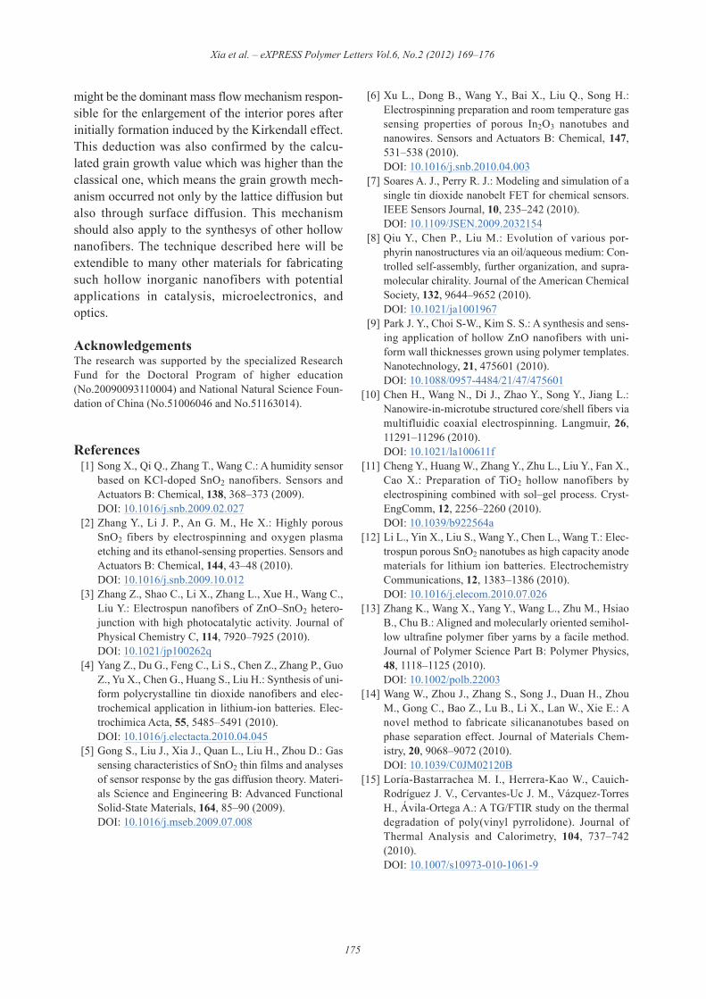
Figure 5. TEM images of PVP/SnO2 nanofibers (a) calcined at 300ºC, (b) calcined at 400ºC, (c) calcined at 500ºC, (d) cal-cined at 600ºC

enters the third stage. At this stage, the Sn precursoron the surface region of the electrospun nanofibersis exposed to air, leading to the decomposition andoxidation of the precursor and resulted in the for-mation of SnO2. Thus some small SnO2 particles arepresented on the surface whereas most Sn precursorinside the fibers remains unreacted due to the absenceof oxygen, leading to solid fiber structure with par-ticles on surface, as illustrated in Figure 5b. Whenthe forming process enters the fourth stage which isa complicated transformation process includinggrain formation, grain growth and grain reorganiza-tion. Figure 5c may be one of morphological situa-tion during this process. Nanograins are the maincomponents to build solid body though the fibersappear to be irregular. Finally, the hollow SnO2nanofibers are formed with porous nanograins onthe shell, as shown in Figure 5dAccording to TEM observations of the hollow SnO2nanofibers formation, it is clearly revealed that PVPand Sn precursor are the main constituents of core-shell as-spun nanofibers. Then PVP is graduallydecomposed during the calcination process. In thisprocess, PVP plays the role of sacrificial template,which is the key effect to maintain fibrous struc-tures. The decomposition of PVP, to some extent,reduces the final fiber diameters. The key mecha-nism responsible for the formation of hollownanofibers is attributed to the interaction betweenSn precursor and SnO2 which will be discussed inthe next section.
3.3. Analysis of formation mechanism As mentioned above, the main components after thecomplete decomposition of PVP are some SnO2particles on the surface region and the massive Snprecursors in the core to form a concentration gradi-ent, which lead to a Kirkendall effect [16]. Kirk-endall effect is associated with the phenomenon ofa considerable amount of compounds moving in orout of a sphere due to the diffusion coupled withdifferent diffusion rates [17]. When the solid fiberconsists of Sn precursor and SnO2 (Figure 6a), the
outward transport of fast-moving Sn precursor mol-ecules (short as Ja in Figure 6) move through theoxide layer and a balancing inward flow of vacan-cies traverse to the vicinity of the Sn precursors andSn precursors/SnO2 mixture interface (a/ab inter-face) and vacancies assisted exchange of materialdepends on the way of bulk inter-diffusion, as illus-trated in Figure 6b. Then, the voids are just likesinks to transfer the inward flux of vacancies (Jc =Ja – Jb) and the voids coalesce into bigger ones soas to touch the compound layer ab. Such new bridgesare established as fast transport paths for the remain-ing Sn precursors (Figure 6c). At this stage, the sur-face diffusion takes over the dominant materialtransport process because the porous surface ownsmuch lower apparent activation energy than thoseof bulk diffusion [18]. Sn precursors can be quicklyoxidized at the surface of ab layer and redistributethemselves via fast surface diffusion, while the ablayer remains bulk inter-diffusion associated withKirkendall effect until the whole Sn precursors turninto SnO2. Therefore, SnO2 stands on the shell andvacancies are continuously generated and flowinward to build a hollow core, as shown in Fig-ure 6d. In all, the fibrous structure is established byPVP template and Kirkendall effect contributions toform hollow structure. Furthermore, surface diffusionalso plays an important role to build hollow fibers.The surface diffusion is also beneficial to the nano-sized grains growth. In the experiments, the anneal-ing time (!4 hrs) obeys the parabolic kinetic equa-tion of grain growth for isothermal annealing asEquation (1):
Dm – D0m = Kt (1)
where t is the annealing time, D is the average grainsize after annealing for time t, D0 is the initial grainsize, m is the grain growth exponent, and K is a tem-perature dependent rate constant =1.04·1013 at600ºC [19].The average grain size after 3 hrs calcination isobtained by calculating the size of three intensepeaks, (110), (101) and (211) of SnO2 from XRD
Xia et al. – eXPRESS Polymer Letters Vol.6, No.2 (2012) 169–176
173
Figure 6. The model for hollow structure formation of SnO2 nanofibers (see text for details)

patterns. When D0 is neglected, the estimated mvalue is 13.2, which is inconsistent with the classi-cal grain growth value (m = 2~4) [20], which meansthe grain growth of the nanograins observed in theindividual nanofibers cannot be primarily ascribedby lattice diffusion in a pore controlled scheme.When the new bridges are established to transportthe mass materials as mentioned above, the connec-tion for lattice diffusion are broken and surface dif-fusion will enhance the local voids, meanwhile actsas the driving force for grain growth, leading toacceleration in the speed of coarse grains by thereduction of the free energy of the system. However,the growth kinetics of nanograins in hollow SnO2fibers is complicated and needs further investiga-tion. Heating rate should be studied to control themorphology of fibers while using the temperatureand duration of calcination as a tool to obtaindesired nanograins on nanofiber surfaces havealready been reported by Park et al. in Ref [20].XRD patterns in Figure 7 confirm the formation ofSnO2 fibers. The fibers after calcination at 300ºCshow a broad continuum indicating that the crystal-lization of tin oxide just starts at this temperaturebut not sufficient enough to produce the diffractionpatterns. However, the XRD patterns of the fibersafter calcination at 400ºC show the emergence oftetragonal rutile tin oxide crystals with distinctpeaks due to the decomposition of PVP and oxida-tion of some Sn precursors on the fiber surface. Thediffraction peaks become much sharper and well
defined after calcination at 500 and 600ºC, withoutaltering their positions but with high intensitybecause of better crystallization. All the diffractionpeaks are indexed to the tetragonal rutile SnO2, theonly crystalline phase existing in the obtained nano -fibers.
3.4. Surface areasBrunauer–Emmett–Teller (BET) gas sorption meas-urement reveals the surface area of the hollow SnO2fibers. The N2 adsorption–desorption isotherm curveof the porous SnO2 fibers is shown in Figure 8. Itexhibits the characteristic of mesopore structures,especially even owns an adsorption at high P/P0,which was also reported as an aggregation of plate-like particles giving rise to slit-shaped pores [21].The porous structure is confirmed by the SEMobservations shown in Figure 1b. The average poresize in the porous SnO2 fibers is approximately16.2 nm, and the corresponding BET specific sur-face area is about 35.8 m2/g (BJH method).
4. ConclusionsIn this work, porous hollow SnO2 nanofibers weresuccessfully prepared by electrospinning techniquevia a single capillary from PVP/Sn precursors/dualsolvents system with calcination treatment. Duringthe electrospinning process, a stringent componentmatching contributes to core-shell structure whichprovided advantages for preserving fibrous struc-tures based on sacrificial PVP template. Hollowstructures initiated by the Kirkendall effect owingto the concentration gradient of Sn precursors andSnO2, suggesting that surface diffusion processes
Xia et al. – eXPRESS Polymer Letters Vol.6, No.2 (2012) 169–176
174
Figure 7. XRD patterns of SnO2 nanofibres at differenttemperature
Figure 8. Nitrogen adsorption/desorption isotherms of thehollow SnO2 nanofibers
might be the dominant mass flow mechanism respon-sible for the enlargement of the interior pores afterinitially formation induced by the Kirkendall effect.This deduction was also confirmed by the calcu-lated grain growth value which was higher than theclassical one, which means the grain growth mech-anism occurred not only by the lattice diffusion butalso through surface diffusion. This mechanismshould also apply to the synthesys of other hollownanofibers. The technique described here will beextendible to many other materials for fabricatingsuch hollow inorganic nanofibers with potentialapplications in catalysis, microelectronics, andoptics.
AcknowledgementsThe research was supported by the specialized ResearchFund for the Doctoral Program of higher education(No.20090093110004) and National Natural Science Foun-dation of China (No.51006046 and No.51163014).
References [1] Song X., Qi Q., Zhang T., Wang C.: A humidity sensor
based on KCl-doped SnO2 nanofibers. Sensors andActuators B: Chemical, 138, 368–373 (2009).DOI: 10.1016/j.snb.2009.02.027
[2] Zhang Y., Li J. P., An G. M., He X.: Highly porousSnO2 fibers by electrospinning and oxygen plasmaetching and its ethanol-sensing properties. Sensors andActuators B: Chemical, 144, 43–48 (2010).DOI: 10.1016/j.snb.2009.10.012
[3] Zhang Z., Shao C., Li X., Zhang L., Xue H., Wang C.,Liu Y.: Electrospun nanofibers of ZnO–SnO2 hetero-junction with high photocatalytic activity. Journal ofPhysical Chemistry C, 114, 7920–7925 (2010).DOI: 10.1021/jp100262q
[4] Yang Z., Du G., Feng C., Li S., Chen Z., Zhang P., GuoZ., Yu X., Chen G., Huang S., Liu H.: Synthesis of uni-form polycrystalline tin dioxide nanofibers and elec-trochemical application in lithium-ion batteries. Elec-trochimica Acta, 55, 5485–5491 (2010).DOI: 10.1016/j.electacta.2010.04.045
[5] Gong S., Liu J., Xia J., Quan L., Liu H., Zhou D.: Gassensing characteristics of SnO2 thin films and analysesof sensor response by the gas diffusion theory. Materi-als Science and Engineering B: Advanced FunctionalSolid-State Materials, 164, 85–90 (2009).DOI: 10.1016/j.mseb.2009.07.008
[6] Xu L., Dong B., Wang Y., Bai X., Liu Q., Song H.:Electrospinning preparation and room temperature gassensing properties of porous In2O3 nanotubes andnanowires. Sensors and Actuators B: Chemical, 147,531–538 (2010).DOI: 10.1016/j.snb.2010.04.003
[7] Soares A. J., Perry R. J.: Modeling and simulation of asingle tin dioxide nanobelt FET for chemical sensors.IEEE Sensors Journal, 10, 235–242 (2010).DOI: 10.1109/JSEN.2009.2032154
[8] Qiu Y., Chen P., Liu M.: Evolution of various por-phyrin nanostructures via an oil/aqueous medium: Con-trolled self-assembly, further organization, and supra -molecular chirality. Journal of the American ChemicalSociety, 132, 9644–9652 (2010).DOI: 10.1021/ja1001967
[9] Park J. Y., Choi S-W., Kim S. S.: A synthesis and sens-ing application of hollow ZnO nanofibers with uni-form wall thicknesses grown using polymer templates.Nanotechnology, 21, 475601 (2010).DOI: 10.1088/0957-4484/21/47/475601
[10] Chen H., Wang N., Di J., Zhao Y., Song Y., Jiang L.:Nanowire-in-microtube structured core/shell fibers viamultifluidic coaxial electrospinning. Langmuir, 26,11291–11296 (2010).DOI: 10.1021/la100611f
[11] Cheng Y., Huang W., Zhang Y., Zhu L., Liu Y., Fan X.,Cao X.: Preparation of TiO2 hollow nanofibers byelectrospining combined with sol–gel process. Cryst -EngComm, 12, 2256–2260 (2010).DOI: 10.1039/b922564a
[12] Li L., Yin X., Liu S., Wang Y., Chen L., Wang T.: Elec-trospun porous SnO2 nanotubes as high capacity anodematerials for lithium ion batteries. ElectrochemistryCommunications, 12, 1383–1386 (2010).DOI: 10.1016/j.elecom.2010.07.026
[13] Zhang K., Wang X., Yang Y., Wang L., Zhu M., HsiaoB., Chu B.: Aligned and molecularly oriented semihol-low ultrafine polymer fiber yarns by a facile method.Journal of Polymer Science Part B: Polymer Physics,48, 1118–1125 (2010).DOI: 10.1002/polb.22003
[14] Wang W., Zhou J., Zhang S., Song J., Duan H., ZhouM., Gong C., Bao Z., Lu B., Li X., Lan W., Xie E.: Anovel method to fabricate silicananotubes based onphase separation effect. Journal of Materials Chem-istry, 20, 9068–9072 (2010).DOI: 10.1039/C0JM02120B
[15] Loría-Bastarrachea M. I., Herrera-Kao W., Cauich-Rodríguez J. V., Cervantes-Uc J. M., Vázquez-TorresH., Ávila-Ortega A.: A TG/FTIR study on the thermaldegradation of poly(vinyl pyrrolidone). Journal ofThermal Analysis and Calorimetry, 104, 737–742(2010).DOI: 10.1007/s10973-010-1061-9
Xia et al. – eXPRESS Polymer Letters Vol.6, No.2 (2012) 169–176
175

[16] Yin Y., Rioux R. M., Erdonmez C. K., Hughes S.,Somorjai G. A., Alivisatos A. P.: Formation of hollownanocrystals through the nanoscale Kirkendall effect.Science, 304, 711–714 (2004).DOI: 10.1126/science.1096566
[17] Kong J., Tan H. R., Tan S. Y., Li F., Wong S. Y., Li X.,Lu X.: A generic approach for preparing core–shellcarbon–metal oxide nanofibers: Morphological evolu-tion and its mechanism. Chemical Communications,46, 8773–8775 (2010). DOI: 10.1039/C0CC03006F
[18] Fan H. J., Knez M., Scholz R., Hesse D., Nielsch K.,Zacharias M., Gösele U.: Influence of surface diffu-sion on the formation of hollow nanostructures inducedby the Kirkendall effect:" The basic concept. Nano Let-ters, 7, 993–997 (2007).DOI: 10.1021/nl070026p
[19] Lai J. K. L., Shek C. H., Lin G. M.: Grain growthkinetics of nanocrystalline SnO2 for long-term isother-mal annealing. Scripta Materialia, 49, 441–446 (2003).DOI: 10.1016/S1359-6462(03)00296-3
[20] Park J. Y., Asokan K., Choi S-W., Kim S. S.: Growthkinetics of nanograins in SnO2 fibers and size depend-ent sensing properties. Sensors and Actuators B:Chemical, 152, 254–260 (2011).DOI: 10.1016/j.snb.2010.12.017
[21] Sing K. S. W., Everett D. H., Haul R. A. W., MoscouL., Pierotti R. A., Rouquérol J., Siemieniewska T.:Reporting physisorption data for gas/solid systemswith special reference to the determination of surfacearea and porosity. Pure and Applied Chemistry, 57,603–619 (1985).DOI: 10.1351/pac198557040603
Xia et al. – eXPRESS Polymer Letters Vol.6, No.2 (2012) 169–176
176

Copyright of Express Polymer Letters is the property of Budapest University of Technology & Economics and
its content may not be copied or emailed to multiple sites or posted to a listserv without the copyright holder's
express written permission. However, users may print, download, or email articles for individual use.