Embed Size (px)
Citation preview

8/7/2019 MEASUREMENT OF FLOWING FLUIDS
http://slidepdf.com/reader/full/measurement-of-flowing-fluids 1/18
MEASUREMENT OF
FLOWING FLUIDS
Usop, Abdulkahar
Silos, Mary Divine GraceDalagan, DiaceRosales, Donnavel

8/7/2019 MEASUREMENT OF FLOWING FLUIDS
http://slidepdf.com/reader/full/measurement-of-flowing-fluids 2/18
8/7/2019 MEASUREMENT OF FLOWING FLUIDS
http://slidepdf.com/reader/full/measurement-of-flowing-fluids 3/18
Magnetic
Vortex shedding
Turbine meter
Positive displacement meters
Ultrasonic meters
Coriolis flow meter
Thermal flowmeters.
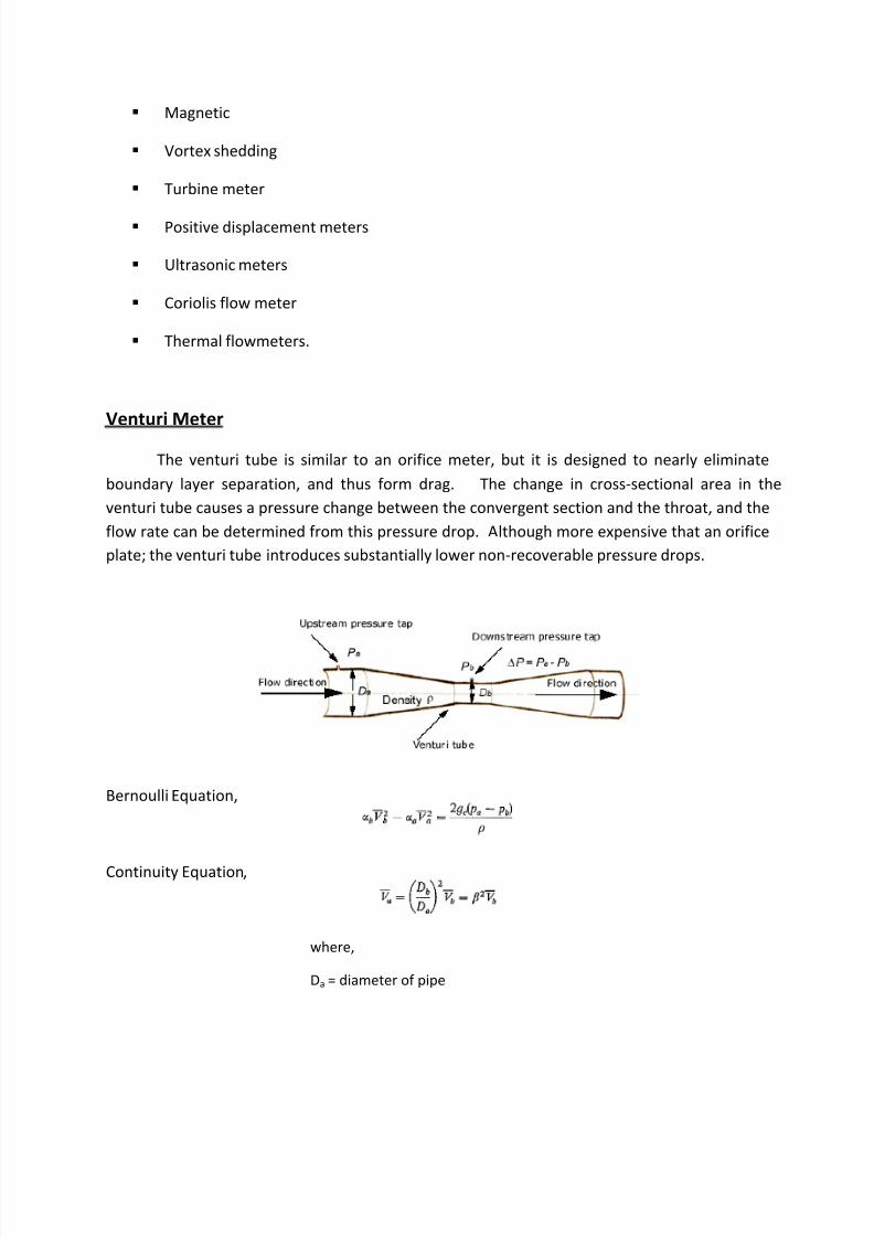
Venturi Meter
The venturi tube is similar to an orifice meter, but it is designed to nearly eliminate
boundary layer separation, and thus form drag. The change in cross-sectional area in the
venturi tube causes a pressure change between the convergent section and the throat, and the
flow rate can be determined from this pressure drop. Although more expensive that an orifice
plate; the venturi tube introduces substantially lower non-recoverable pressure drops.
Bernoulli Equation,
Continuity Equation,
where,
Da = diameter of pipe
8/7/2019 MEASUREMENT OF FLOWING FLUIDS
http://slidepdf.com/reader/full/measurement-of-flowing-fluids 4/18
Db = diameter of throat of meter
= diameter ratio Db/Da
Eliminating Va ,
Venturi coefficient, C v
- used to account for the small friction loss
- determined experimentally
C v = 0.98 for pipe diameters 2 8 in.
= 0.99 for larger sizes
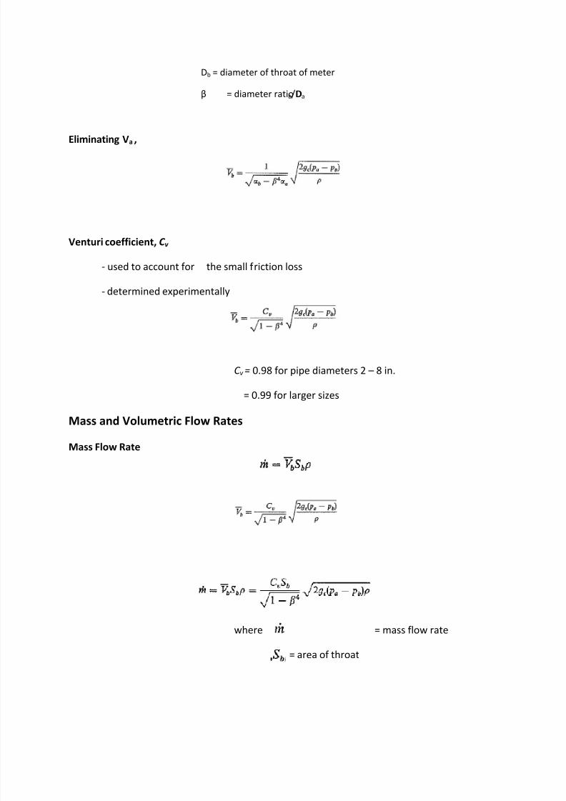
Mass and Volumetric Flow Rates
Mass Flow Rate
where = mass flow rate
= area of throat

8/7/2019 MEASUREMENT OF FLOWING FLUIDS
http://slidepdf.com/reader/full/measurement-of-flowing-fluids 5/18
Volumetric Flow Rate
where q = the volumetric flow rate
Pressure Recovery
Pressure is recovered, approx. 90%, by reducing the angle of divergence in the recovery cone.
Advantages
Lower pressure loss than orifice
Slurries do not plug
Disadvantages
expensive
occupies considerable space
ratio of throat diameter to pipe diameter cannot be change
Orifice Meter
An orifice plate is a restriction with an opening smaller than the pipe diameter which is
inserted in the pipe; the typical orifice plate has a concentric, sharp edged opening. Because of the smaller area the fluid velocity increases, causing a corresponding decrease in pressure. The
flow rate can be calculated from the measured pressure drop across the orifice plate. The
orifice plate is the most commonly used flow sensor, but it creates a rather large non-
recoverable pressure due to the turbulence around the plate, leading to high energy
consumption.

8/7/2019 MEASUREMENT OF FLOWING FLUIDS
http://slidepdf.com/reader/full/measurement-of-flowing-fluids 6/18
Orifice Coefficient,C o
- corrects for the contraction of the fluid jet between the orifice and vena contracta, for
friction,
and for a and
- determined experimentally
where uo = velocity through the orifice
= ratio of orifice diameter to pipe diameter
pa, pb = pressures at stations a and b
C o = orifice coefficient
- varies with changes in and with Reynolds number at the orifice, NRe,o
- almost constant and independent of providedNRe,o is greater than 30,000 (C o may be taken
as 0.61 for both taps)
- for process application, should be between 0.20 and 0.75.

8/7/2019 MEASUREMENT OF FLOWING FLUIDS
http://slidepdf.com/reader/full/measurement-of-flowing-fluids 7/18
- if is less than 0.25,
Mass Flow Rate
Advantages
Low cost
Extensive industrial practice
Disadvantages
High pressure loss
Plugging with slurries
FLOW OF COMPRESSIBLE FLUIDS THROUGH VENTURIS AND ORIFICES
For Venturi,
For Orifices,
8/7/2019 MEASUREMENT OF FLOWING FLUIDS
http://slidepdf.com/reader/full/measurement-of-flowing-fluids 8/18
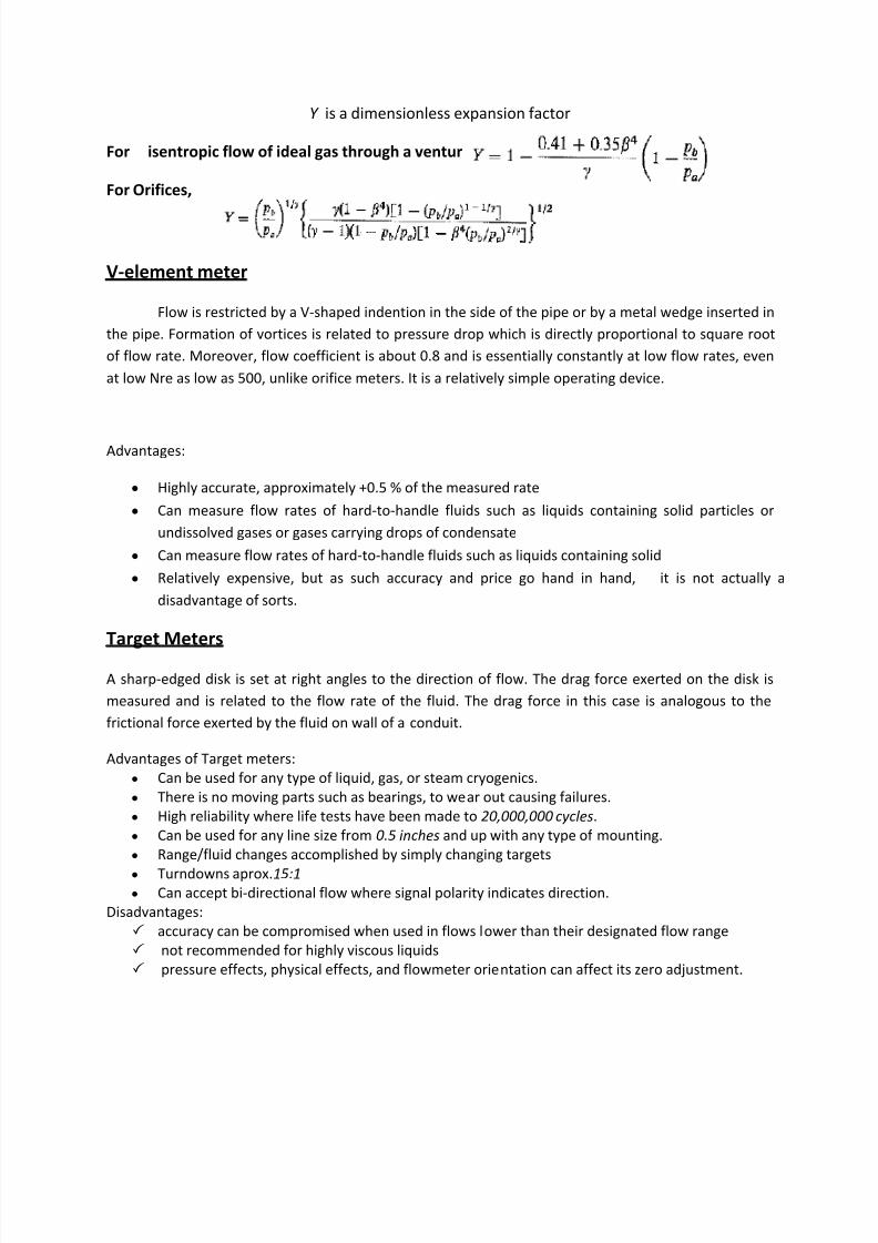
Y is a dimensionless expansion factor
For isentropic flow of ideal gas through a venturi,
For Orifices,
V-element meter
Flow is restricted by a V-shaped indention in the side of the pipe or by a metal wedge inserted in
the pipe. Formation of vortices is related to pressure drop which is directly proportional to square root
of flow rate. Moreover, flow coefficient is about 0.8 and is essentially constantly at low flow rates, even
at low Nre as low as 500, unlike orifice meters. It is a relatively simple operating device.
Advantages:
y Highly accurate, approximately +0.5 % of the measured rate
y Can measure flow rates of hard-to-handle fluids such as liquids containing solid particles or
undissolved gases or gases carrying drops of condensate
y Can measure flow rates of hard-to-handle fluids such as liquids containing solid
y Relatively expensive, but as such accuracy and price go hand in hand, it is not actually a
disadvantage of sorts.
Target Meters
A sharp-edged disk is set at right angles to the direction of flow. The drag force exerted on the disk is
measured and is related to the flow rate of the fluid. The drag force in this case is analogous to the
frictional force exerted by the fluid on wall of a conduit.
Advantages of Target meters:
y Can be used for any type of liquid, gas, or steam cryogenics.
y There is no moving parts such as bearings, to wear out causing failures.
y High reliability where life tests have been made to 20,000,000 cy cles.
y Can be used for any line size from 0.5 inches and up with any type of mounting.
y Range/fluid changes accomplished by simply changing targets
y Turndowns aprox.15:1 y Can accept bi-directional flow where signal polarity indicates direction.
Disadvantages:
accuracy can be compromised when used in flows lower than their designated flow range
not recommended for highly viscous liquids
pressure effects, physical effects, and flowmeter orientation can affect its zero adjustment.

8/7/2019 MEASUREMENT OF FLOWING FLUIDS
http://slidepdf.com/reader/full/measurement-of-flowing-fluids 9/18
Rotameters
The rotameter is an industrial flowmeter used to measure the flowrate of liquids and gases. The
rotameter consists of a tube and float. The float response to flowrate changes is linear, and a 10-to-1
flow range or turndown is standard. In the case of OMEGA® laboratory rotameters, far greater flexability
is possible through the use of correlation equations. The rotameter is popular because it has a linear
scale, a relatively long measurement range, and low pressure drop. It is simple to install and maintain.
Principle of operation
The rotameter's operation is based on the variable area principle: fluid flow raises a float in a
tapered tube, increasing the area for passage of the fluid. The greater the flow, the higher the float is
raised. The height of the float is directly proportional to the flowrate. With liquids, the float is raised by
a combination of the buoyancy of the liquid and the velocity head of the fluid. With gases, buoyancy is
negligible, and the float responds to the velocity head alone.
Glass Tube Rotameters
The basic rotameter is the glass tube indicating-type. The tube is precision formed of borosilicate glass,
and the float is precisely machined from metal, glass or plastic. The metal float is usually made of
stainless steel to provide corrosion resistance. The float has a sharp metering edge where the reading is
observed by means of a scale mounted alongside the tube.
End fittings and connections of various materials and styles are available. The important elements are
the tube and float, often called the tube-and-float combination, because it is this portion of the
rotameter which provides the measurement. In fact, similar glass tube and stainless steel float
combinations are generally available, regardless of the type of case or end fittings the application can
demand, so as best to meet customer requirements. The scale of the rotameter can be calibrated for
direct reading of air or water, or it may have a scale to read a percent of range or an arbitrary scale to be
used with conversion equations or charts. Safety-shielded glass tube rotameters are in general use
throughout industry for measuring both liquids and gases. They provide flow capacities to about 60
GPM, and are manufactured with end fittings of metal or plastic to meet the chemical characteristics of
the fluid being metered.
Metal Tube Flowmeters
For higher pressures and temperatures beyond the practical range of glass tubes, metal tubes are used.
These are usually manufactured in aluminim, brass or stainless steel. The position of the piston isdetermined by magnetic or mechanical followers that can be read from the outside of the metal
metering tube. Similar to glass tube rotameters, the spring-and-piston combination determines the
flowrate, and the fittings and materials of construction must be chosen so as to satisfy the demands of
the applications. These meters are used for services where high operating pressure or temperature,
water hammer, or other forces would damage glass metering tubes. Spring and piston flowmeters can

8/7/2019 MEASUREMENT OF FLOWING FLUIDS
http://slidepdf.com/reader/full/measurement-of-flowing-fluids 10/18
be used for most fluids, including corrosive liquids and gases. They are particularly well suited for steam
applications, where glass tubes are unacceptable.
Plastic Tube Rotameters
Plastic tubes are also used in some rotameter designs due to their lower cost and high impact strength.
They are typically constructed of polycarbonate, with either metal or plastic end fittings. With plastic
end fittings, care must be taken in installation, not to distort the threads. Rotameters with all plastic
construction are available for applications where metal wetted parts cannot be tolerated, such as with
deionized water or corrosives.
Advantages
A rotameter requires no external power or fuel, it uses only the inherent properties of the fluid,
along with gravity, to measure flow rate.
A rotameter is also a relatively simple device that can be mass manufactured out of cheap
materials, allowing for its widespread use.
Disadvantages
Due to its use of gravity, a rotameter must always be vertically oriented and right way up, with
the fluid flowing upward.
Due to its reliance on the ability of the fluid or gas to displace the float, graduations on a given
rotameter will only be accurate for a given substance at a given temperature. The main property
of importance is the density of the fluid; however, viscosity may also be significant. Floats are
ideally designed to be insensitive to viscosity; however, this is seldom verifiable from
manufacturers' specifications. Either separate rotameters for different densities and viscosities
may be used, or multiple scales on the same rotameter can be used.
Rotameters normally require the use of glass (or other transparent material), otherwise the user
cannot see the float. This limits their use in many industries to benign fluids, such aswater.
Rotameters are not easily adapted for reading by machine; although magnetic floats that drive a
follower outside the tube are available.
Vortex shedding flow meters
They measure vibrations of the downstream vortices caused by a barrier in the moving stream.
It is best used for turbulent flow with Reynolds number greater than 10,000. A bluff body is placed
into the process stream to create series of alternating vortices which causes the fluid to swirl. The
number of vortices formed is directly proportional to the flow velocity and hence the flow rate.

8/7/2019 MEASUREMENT OF FLOWING FLUIDS
http://slidepdf.com/reader/full/measurement-of-flowing-fluids 11/18
Vortices are detected downstream by an ultrasonic beam that is transmitted perpendicular to the
direction of flow.
Advantages:
y Insensitive to pressure, temperature and viscosity
y Comparable in accuracy to the other types of meters
Turbine meters
have found widespread use for accurate liquid measurement applications. The unit consists of a
multiple-bladed rotor mounted with a pipe, perpendicular to the liquid flow. The rotor spins as the
liquid passes through the blades. The rotational speed is a direct function of flow rate and can be sensed
by magnetic pick-up, photoelectric cell, or gears. Electrical pulses can be counted and totalized.
A good turbine flowmeter requires a well designed and placed aerodynamic or hydrodynamic blades
that are suitable for the fluid and flow condition and bearings that are both smooth and durable tosurvive the sustained high-speed rotation of the turbine. Turbine meters, when properly specified and
installed, have good accuracy, particularly with low-viscosity liquids. They are the meter of choice for
large commercial users and as master meters for the water distribution system.
Turbine meters are exceptionally accurate when used in proper conditions, but tend to be
fragile and their maintenance cost may be high.
Positive displacement meter is a type of flow meter that requires the fluid being measured to mechanically displace components
in the meter in order for any fluid flow to occur. Positive displacement (PD) flowmeters make volumetric
flow measurements taking finite increments or volumes of the fluid. Positive displacement flow meters
measure the volume or flow rate of a moving fluid or gas by dividing the media into fixed, metered
volumes. These devices consist of a chamber that obstructs the media flow and a rotating or
reciprocating mechanism that allows the passage of fixed-volume amounts. The number of parcels that

8/7/2019 MEASUREMENT OF FLOWING FLUIDS
http://slidepdf.com/reader/full/measurement-of-flowing-fluids 12/18
pass through the chamber determines the media volume. The rate of revolution or reciprocation
determines the flow rate. The higher the viscosity, the better the performance. Cant handle dirty liquids
or slurries and are expensive to maintain. This meter comes in different forms. Here are some types of
PD meters:
Oval Gear-Two identical oval rotors mesh together by means of slots around the gear perimeter.
The oval shaped gears are used to sweep out an exact volume of the liquid passing through the
measurement chamber during each rotation. The flow rate can be calculated by measuring the
rotation speed.
Nutating Disc-Liquid enters a precision-machined chamber containing a disc which nutates
(wobbles). The position of the disc divides the chamber into compartments containing an exact
volume. Liquid pressure drives the disc to wobble and a roller cam causes the nutating disc to
make a complete cycle. This motion is translated into rotary motion by means of a ball and
shaft, which is attached to the disc. The movements of the disc are transmitted by gear train to
an indicator/totalizer or pulse transmitter.
Oscillating Piston-Liquid enters a precision-machined chamber containing an oscillating
(rotating) piston. The position of the piston divides the chamber into compartments containing
an exact volume. Liquid pressure drives the piston to oscillate and rotate on its center hub. The
movements of the hub are sensed through the meter wall by a follower magnet.
Root-Meter that is similar in many aspects to the oval gear meter. A design is shown where two-
lobed impellers rotate in opposite directions to each other within the body housing. These
peanut-shaped gears sweep out an exact volume of liquid passing through the measurement
chamber during each rotation.
Magnetic meters
are non-intrusive meters that can handle most liquids and slurries provided that the material is
electrically conductive. The basic principle of the operation of this meter is that when a flowing
conducting fluid is subjected to a transverse magnetic field, the flowing conducting fluid cuts the
magnetic field and causes a voltage to be induced (Faradays Law). This induced voltage is proportional
to the fluid velocity, that is, flow rate. The flow tube is lined with a non-conducting material with two or
more metal electrodes mounted flush with the inner wall. The liquid serves as the conductor; the
magnetic field is created by energized coils outside the flow tube. The amount of voltage produced is
directly proportional to the flow rate. Two electrodes mounted in the pipe wall detect the voltage,

8/7/2019 MEASUREMENT OF FLOWING FLUIDS
http://slidepdf.com/reader/full/measurement-of-flowing-fluids 13/18
which is measured by the secondary element. Cant measure hydrocarbons which have low conductivity.
This magnetic flow meter is based on faradays law of induced voltage which is given as follows,
E = BLV
Where,
E = induced voltage(volts)
B = flux density (gauss)
L = Length of conductor which is the diameter of the pipe (cm)
V = Average velocity of conductor (fluid) in cm/sec
When the conducting fluid flows through the pipe which is subjected to a magnetic field, the
conducting fluid cuts the magnetic field and due to this a voltage is induced. As the magnetic
field is constant, voltage obtained across the electrodes will be directly proportional t average
fluid velocity and diameter (length) and hence becomes a measure of volume flow rate.
The fluid whose flow rate is to be measured should satisfy certain conduction conditions. In
certain fluids, the electrodes might get coated with scales and this will affect the output signal.
However, this can be taken care off by cleaning the electrodes.
Ultrasonic Meters
meter that measures the velocity of the fluid by using the principle of ultrasound. Ultrasonic
flow meters are affected by the temperature, density and viscosity of the flowing medium. They are
inexpensive to use and maintain because they do not use moving parts, unlike mechanical flow meters.
Have two types: The transit time and the Doppler flowmeter.
Transit time flow meter uses ultrasonic transducers to measure the average velocity along the
path of an emitted beam of ultrasound, by averaging the difference in measured transit time
between the pulses of ultrasound propagating into and against the direction of the flow.
By using the absolute transit times both the averaged fluid velocity and the speed of sound can
be calculated. Using the two transit times t up and td ow n and the distance between receiving
transmitting transducers L and the inclination angle one can write the equations:

8/7/2019 MEASUREMENT OF FLOWING FLUIDS
http://slidepdf.com/reader/full/measurement-of-flowing-fluids 14/18
Doppler shift meters- measure dirty liquids. They compute flow rate based on a frequency shift
that occurs when their ultrasonic signals reflect off particles in the flow stream. They depend on
volumetric flow meter which requires particulates or bubbles in the flow. Ideal for wastewater
applications or any dirty liquid which is conductive or water based. For the Doppler principle to
work in a flowmeter it is mandatory that the flow stream contains sonically reflective materials,
such as solid particles or entrained air bubbles.
Coriolis flowmeter
or sometimes called Mass flowmeter is a device that measures mass flow rate of a fluid
traveling through a tube. The mass flow rate is the mass of the fluid traveling past a fixed point per unit
time.
The mass flow meter does not measure the volume per unit time (e.g., cubic meters per second) passing
through the device; it measures the mass per unit time (e.g., kilograms per second) flowing through the
device.
The inlet arm and the outlet arm vibrate with the same frequency as the overall vibration, but when
there is mass flow the two vibrations are out of sync, the inlet arm is behind, and the outlet arm is
ahead. The two vibrations are shifted in phase with respect to each other, and the degree of phase-shift
is a measure for the amount of mass that is flowing through the tubes.
Thermal Meters
-measure mass flow rate directly by measuring the rise in temperature of the fluid as it
passes over a heating element or the rate of heat transfer to the stream from a heated surface.
-used most entirely for gas flow applications
-this method works best with gas mass flow measurement. It is difficult to get a strong
signal using thermal mass flow meters in liquids, due to considerations relating to heat
absorption.
-As the name implies, thermal mass flow meters use heat to measure flow. Thermal
mass flow meters introduce heat into the flow stream and measure how much heat dissipates
using one or more temperature sensors.
T wo different met hods f or measuring how much heat is dissi pated :
1. Constant temperature differential
Thermal flow meters using this method have two temperature sensors a heated
sensor and another sensor that measures the temperature of the gas. Mass flow rate is
8/7/2019 MEASUREMENT OF FLOWING FLUIDS
http://slidepdf.com/reader/full/measurement-of-flowing-fluids 15/18
computed based on the amount of electrical power required to maintain a constant
difference in temperature between the two temperature sensors.
2. Constant current method
Thermal mass flow meters using this method also have a heated sensor and another one
that senses the temperature of the flow stream. The power to the heated sensor is keptconstant. Mass flow is measured as a function of the difference between the
temperature of the heated sensor and the temperature of the flow stream.
Ad v antages
y They feature no moving parts, nearly unobstructed straight through flow path, require
no temperature or pressure corrections and retain accuracy over a wide range of flow
rates.
The moving parts of a machine are those parts of it that move. The amount of moving
parts in a machine is a factor in its mechanical efficiency. The greater the number of
moving parts, the greater the amount of energy lost to heat by friction between thoseparts. In a modern automobile engine, for example, roughly 7% of the total power
obtained from burning the engine's fuel is lost to friction between the engine's moving
parts. Conversely, the fewer the number of moving parts, the greater the efficiency.
Machines with no moving parts at all can be very efficient.
y The thermal flowmeter measures gas mass flow directly, with no need for additional
hardware. It also provides better rangeability and a lower pressure drop than volumetric
flowmeters.
y Virtually attitude insensitive - can be calibrated to and mounted in any orientation
specifiedy Generally unaffected by and can be self corrected for - changes in process temperature
and/or pressure
T y pi cal Appli cati ons
Automotive: Compressed air monitoring - Natural gas consumption - Powder paint air flow -
Paint booth/paint oven ventilation
Utility Services: Electric, gas, water works & sewage plants, for monitoring and control of: Stack
or flue gas - Waste water aeration - Ventilation systems - Digester gas - Gas flows - Nitrogen
purge - Combustion air - Boiler inlet air
Petroleum & Gas Industries: Custody transfer - Landfill gas recovery - Flare gas measurement -Gas mixing - Gas quality studies - Leak testing
HVAC: Heating, ventilation & air conditioning for:
Air balancing - Duct flows - Energy conservation - Fume hoods - Clean rooms - Laminar flow
benches

8/7/2019 MEASUREMENT OF FLOWING FLUIDS
http://slidepdf.com/reader/full/measurement-of-flowing-fluids 16/18
Insertion Meters
In this type of meter, the sensing element is which is small compared to the size of the
flow channel, is inserted into the flow stream. Few insertion meters measure the average flow
velocity, but the majority measure the local velocity at one point only. The point of
measurement may be at the centreline of the channel and the average velocity or at thecritical point in the channel where the local velocity equals the average velocity.
Insertion meters are generally cheaper than full-bore meters and are usually the most
cost-effective method of measuring flow in large pipes.
Pitot Tubes
-can measure fluid flow velocity by converting the kinetic energy of the flow into
potential energy.
-measure the local velocity at a given point in the flow stream and not the average
velocity in the pipe or conduit
-widely used to determine the airspeed of an aircraft
How it works
The opening of the impact tube a is perpendicular to the flow of the direction. The
opening of the static tube b is parallel to the direction of flow. The two tubes are connected to
the legs of a manometer or equivalent device for measuring small pressure differences. The
static tube measures the static pressure, ps since there is no velocity component perpendicular
to its opening. The impact opening includes a stagnation point B at which the streamline AB
terminates.
The pressure pt, measured by the impact tube is the stagnation pressure of the fluid
given for ideal gases.
The measured stagnation pressure cannot of itself be used to determine the fluid
velocity (airspeed in aviation). However, Bernoulli's equation states:
Stagnation pressure = static pressure + dynamic pressure
which can also be written
Solving that for velocity we get:

8/7/2019 MEASUREMENT OF FLOWING FLUIDS
http://slidepdf.com/reader/full/measurement-of-flowing-fluids 17/18
Note: The above equation applies only to incompressible fluid.
where:
y V is fluid velocity;
y pt is stagnation or total pressure;
y ps is static pressure;
y and is fluid density.
The value for the pressure drop p2
p1
or p to h, the reading on the thermometer:
p = h(A-)g=pt - ps
Where:
y A is the density of the fluid in the manometer
y h is the manometer reading
With the difference in pressures measured and knowing the local value of air density from
pressure and temperature measurements, we can use Bernoulli's equation to give us thevelocity.
Note: The above equations are applicable only to incompressible fluids.
Disadav antages
´ most designs do not give the velocity directly
´ its readings for gases are extremely small
´ don't work very well for very low velocities
If the velocity is low, the difference in pressures is very small and hard to accuratelymeasure with the transducer. Errors in the instrument could be greater than the
measurement!
´ measurement errors occur due to position of the tubes, compressibility factors or air
density

8/7/2019 MEASUREMENT OF FLOWING FLUIDS
http://slidepdf.com/reader/full/measurement-of-flowing-fluids 18/18
Well-designed instruments are in error by not more than 1 percent of theory, but when
precise measurements are to be made, the pitot tube should be calibrated and an
appropriate correction factor must be applied. The factor is used as a coefficient in the
previous equations. It is nearly unity in well-designed pitot tubes.
P it ot - Stati c T ubes
Pitot-Static tubes, which are also called Prandtl tubes, are used on aircraft as
speedometers. The actual tube on the aircraft is around 10 inches (25 centimeters ) long with a
1/2 inch (1 centimeter) diameter. Several small holes are drilled around the outside of the tube
and a center hole is drilled down the axis of the tube. The outside holes are connected to one
side of a device called a pressure transducer. The center hole in the tube is kept separate from
the outside holes and is connected to the other side of the transducer. The transducer
measures the difference in pressure in the two groups of tubes by measuring the strain in a thin
element using an electronic strain gauge. The pitot-static tube is mounted on the aircraft, or in
a wind tunnel , so that the center tube is always pointed in the direction of the flow and the
outside holes are perpendicular to the center tube. On some airplanes the pitot-static tube is
put on a longer boom sticking out of the nose of the plane or the wing.