Embed Size (px)
Citation preview

George W. Woodruff School of Mechanical Engineering, Georgia TechGeorge W. Woodruff School of Mechanical Engineering, Georgia Tech
ME4447/6405ME4447/6405
ME 6405Introduction to Mechatronics
Fall 2005
Instructor: Professor Charles Ume
LECTURE 5

George W. Woodruff School of Mechanical Engineering, Georgia TechGeorge W. Woodruff School of Mechanical Engineering, Georgia Tech
ME4447/6405ME4447/6405

George W. Woodruff School of Mechanical Engineering, Georgia TechGeorge W. Woodruff School of Mechanical Engineering, Georgia Tech
ME4447/6405ME4447/6405
RAM – Random Access Memory“Volatile” – loses contents after power off
ROM – Read Only Memory• “non-Volatile”• Contents must be programmed at the factory
EPROM – Electrically Programmable Read Only Memory• “non-Volatile”• Electrically programmable• May be erasable with ultraviolet light if manufacturer included window in
chip package• Still considered Read Only Memory during normal program execution
EEPROM – Electrically Erasable Programmable Read Only Memory• “non-Volatile• Electrically programmable and erasable (Note:Sometimes higher voltage than
microcontroller voltage may be required)• Slower to write to than RAM so still considered Read Only Memory during
normal program execution

George W. Woodruff School of Mechanical Engineering, Georgia TechGeorge W. Woodruff School of Mechanical Engineering, Georgia Tech
ME4447/6405ME4447/6405
MC – FULLY SPECIFIED AND QUALIFIEDXC – PILOT PRODUCTION SAMPLEPC – ENGINEERING SAMPLE
MOTOROLA HCMOS
7 – EPROM PROGRAM MEMORY8 – EEPROM PROGRAM MEMORYNONE – ROM OR NO PROGRAM MEMORY
M68HC11 FAMILY
SPECIFIC PART TYPEA8A1A0E9E1E0A2E2D3F1
ETC.
MC 68HC x 11 xx
Product Designations found in literature is shown below:
Figure 1-3. Part Numbering (Reference)

George W. Woodruff School of Mechanical Engineering, Georgia TechGeorge W. Woodruff School of Mechanical Engineering, Georgia Tech
ME4447/6405ME4447/6405
QUALIFICATION LEVELMC – FULLY SPECIFIED AND QUALIFIEDXC – PILOT PRODUCTION SAMPLEPC – ENGINEERING SAMPLE
OPERATING VOLTAGE RANGEHC – HCMOS (VDD = 5.0 VDC E10%)
L – HCMOS (VDD = 3.0 VDC TO 5.5 VDC
NUMERIC DESIGNATOR (OPTIONAL)
COP OPTION (ONLY ON A-SERIES DEVICES)NONE – COP DISABLED
P – COP ENABLED
MEMORY TYPEBLANK – MASKED ROM OR NO ROM
7 – EPROM/OPTROM8 – EEPROM
BASE PART NUMBER11A8, 11D3, 11E9, 11K4, ETC.
MONITOR MASKNONE – BLANK
B – BUFFALO
TEMPERATURE RANGENONE – 0ºC TO 70ºC
C – -40ºC TO 85ºCV – -40ºC TO 105ºCM – -40ºC TO 125ºC
PACKAGE TYPEFN – 44/52/68/84-PIN PLCCFS – 44/52/68/84-PIN CLCCFU – 64/80-PIN QFPFB – 44-PIN QFPPV – 112-PIN TQFPPU – 80/100-PIN TQFPPB – 52-PIN TQFP
P – 40/48-PIN DIPS – 48-PIN SDIP
MAXIMUM SPECIFIED CLOCK SPEED2 – 2.0 MHz3 – 3.0 MHz4 – 4.0 MHz
TAPE AND REEL OPTIONNONE – STANDARD PACKAGING
R2 – TAPE AND REEL PACKAGING
MC 68 HC P 7 11XX B C FN 3 R2
Part designations found in packaging is different from literature and is shown below:
Figure 1-3. Part Numbering (Reference)
George W. Woodruff School of Mechanical Engineering, Georgia TechGeorge W. Woodruff School of Mechanical Engineering, Georgia Tech
ME4447/6405ME4447/6405
Product Family Members as of 1-1-03
Table 1-1. M68HC11 Family Members (Reference)

George W. Woodruff School of Mechanical Engineering, Georgia TechGeorge W. Woodruff School of Mechanical Engineering, Georgia Tech
ME4447/6405ME4447/6405
Table 1-1. M68HC11 Family Members (Reference)

George W. Woodruff School of Mechanical Engineering, Georgia TechGeorge W. Woodruff School of Mechanical Engineering, Georgia Tech
ME4447/6405ME4447/6405

George W. Woodruff School of Mechanical Engineering, Georgia TechGeorge W. Woodruff School of Mechanical Engineering, Georgia Tech
ME4447/6405ME4447/6405
•52-pin plastic-leaded chip carrier (PLCC) (Shown below)•52-pin windowed ceramic leaded chip carrier (CLCC)•52-pin plastic thin quad flat pack, 10 mm x 10 mm (TQFP)•64-pin quad flat pack (QFP)•48-pin plastic dual in-line package (DIP), MC68HC811E2 only•56-pin plastic shrink dual in-line package, .070-inch lead spacing (SDIP)
M68HC11 E-series package options
Figure 2-3. MC68HC11E9/11E9 Pin Assignments (52-PIN PLCC)(Technical)

George W. Woodruff School of Mechanical Engineering, Georgia TechGeorge W. Woodruff School of Mechanical Engineering, Georgia Tech
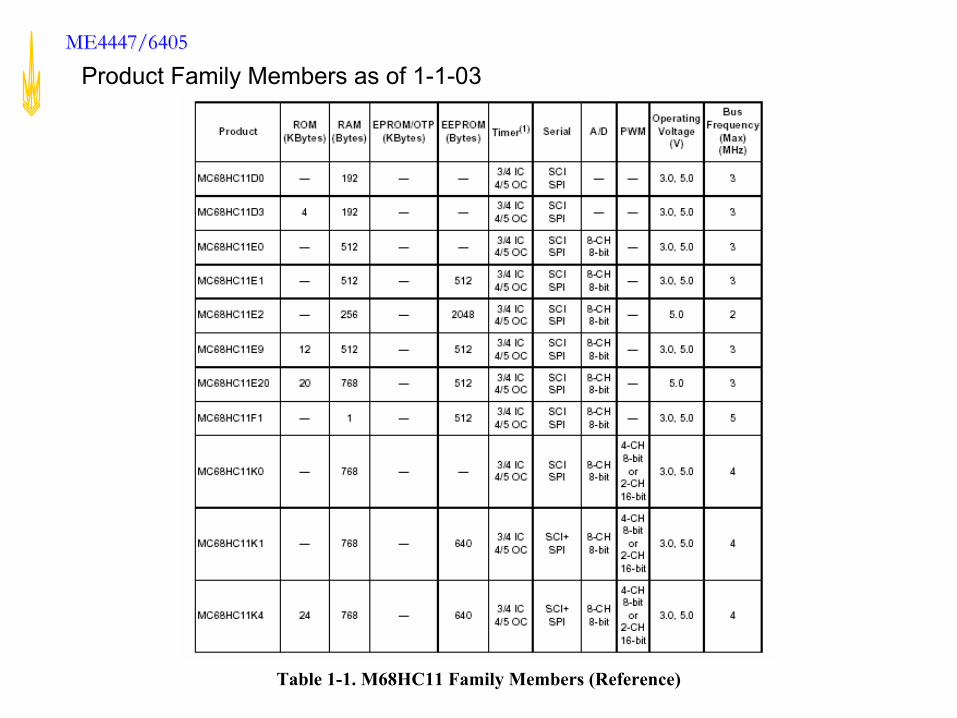
ME4447/6405ME4447/6405 M68HC11 E-series Block Diagram shows available subsystems
Figure 1-1. M68HC11 E-Series Block Diagram (Technical)
George W. Woodruff School of Mechanical Engineering, Georgia TechGeorge W. Woodruff School of Mechanical Engineering, Georgia Tech
ME4447/6405ME4447/6405
Figure 1-1. M68HC11 E-Series Block Diagram (Technical)
George W. Woodruff School of Mechanical Engineering, Georgia TechGeorge W. Woodruff School of Mechanical Engineering, Georgia Tech
ME4447/6405ME4447/6405
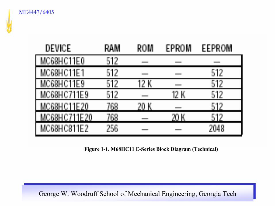
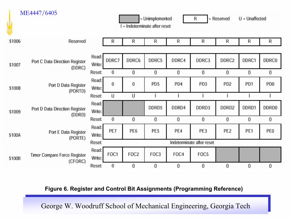
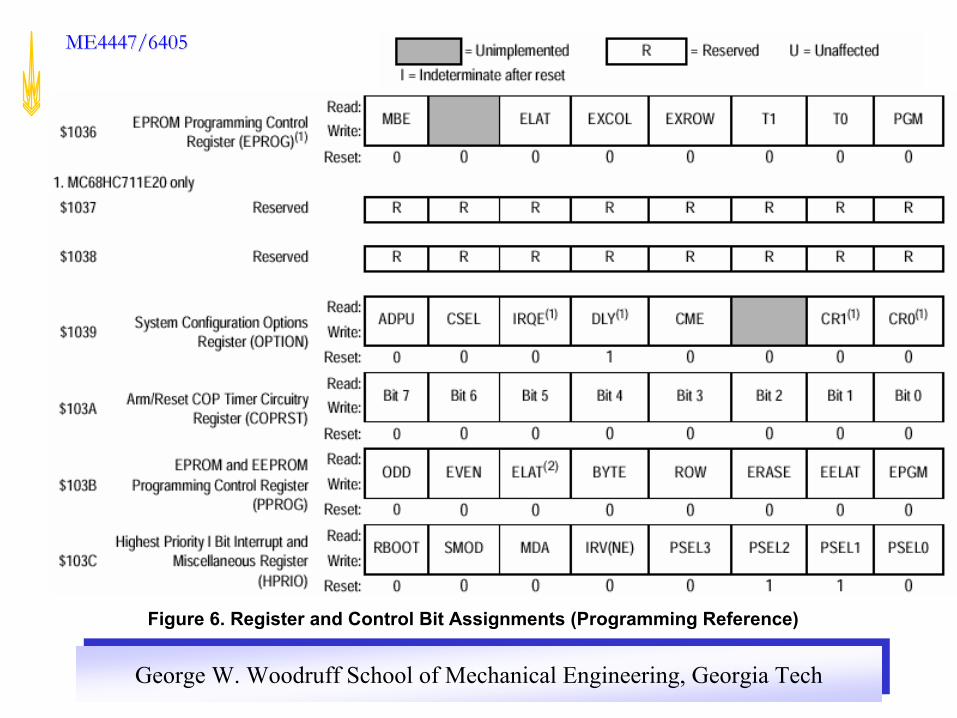
Figure 6. Register and Control Bit Assignments (Programming Reference)
George W. Woodruff School of Mechanical Engineering, Georgia TechGeorge W. Woodruff School of Mechanical Engineering, Georgia Tech
ME4447/6405ME4447/6405
Figure 6. Register and Control Bit Assignments (Programming Reference)

George W. Woodruff School of Mechanical Engineering, Georgia TechGeorge W. Woodruff School of Mechanical Engineering, Georgia Tech
ME4447/6405ME4447/6405
Figure 6. Register and Control Bit Assignments (Programming Reference)

George W. Woodruff School of Mechanical Engineering, Georgia TechGeorge W. Woodruff School of Mechanical Engineering, Georgia Tech
ME4447/6405ME4447/6405
Figure 6. Register and Control Bit Assignments (Programming Reference)

George W. Woodruff School of Mechanical Engineering, Georgia TechGeorge W. Woodruff School of Mechanical Engineering, Georgia Tech
ME4447/6405ME4447/6405
Figure 6. Register and Control Bit Assignments (Programming Reference)

George W. Woodruff School of Mechanical Engineering, Georgia TechGeorge W. Woodruff School of Mechanical Engineering, Georgia Tech
ME4447/6405ME4447/6405
Figure 6. Register and Control Bit Assignments (Programming Reference)

George W. Woodruff School of Mechanical Engineering, Georgia TechGeorge W. Woodruff School of Mechanical Engineering, Georgia Tech
ME4447/6405ME4447/6405
Figure 6. Register and Control Bit Assignments (Programming Reference)

George W. Woodruff School of Mechanical Engineering, Georgia TechGeorge W. Woodruff School of Mechanical Engineering, Georgia Tech
ME4447/6405ME4447/6405
Figure 6. Register and Control Bit Assignments (Programming Reference)

George W. Woodruff School of Mechanical Engineering, Georgia TechGeorge W. Woodruff School of Mechanical Engineering, Georgia Tech
ME4447/6405ME4447/6405
Figure 6. Register and Control Bit Assignments (Programming Reference)
George W. Woodruff School of Mechanical Engineering, Georgia TechGeorge W. Woodruff School of Mechanical Engineering, Georgia Tech
ME4447/6405ME4447/6405
Figure 6. Register and Control Bit Assignments (Programming Reference)

George W. Woodruff School of Mechanical Engineering, Georgia TechGeorge W. Woodruff School of Mechanical Engineering, Georgia Tech
ME4447/6405ME4447/6405
Figure 6. Register and Control Bit Assignments (Programming Reference)

George W. Woodruff School of Mechanical Engineering, Georgia TechGeorge W. Woodruff School of Mechanical Engineering, Georgia Tech
ME4447/6405ME4447/6405

George W. Woodruff School of Mechanical Engineering, Georgia TechGeorge W. Woodruff School of Mechanical Engineering, Georgia Tech
ME4447/6405ME4447/6405
Hardware Mode Selection Summary
Table 4-1. Hardware Mode Select Summary (Reference)

George W. Woodruff School of Mechanical Engineering, Georgia TechGeorge W. Woodruff School of Mechanical Engineering, Georgia Tech
ME4447/6405ME4447/6405
Minimum connections needed for Single chip and Bootstrap mode.
All ports available for use
Figure 2-23. Basic Single-Chip Mode Connections (Reference)

George W. Woodruff School of Mechanical Engineering, Georgia TechGeorge W. Woodruff School of Mechanical Engineering, Georgia Tech
ME4447/6405ME4447/6405
Minimum connection needed for Expanded Mode and Test Mode
Ports B and C not available for use (maybe emulated with MC68HC24 port replacement unit)
Por
t BP
ort
C
Figure 2-22. Basic Expanded Mode Connections(Reference)
George W. Woodruff School of Mechanical Engineering, Georgia TechGeorge W. Woodruff School of Mechanical Engineering, Georgia Tech
ME4447/6405ME4447/6405
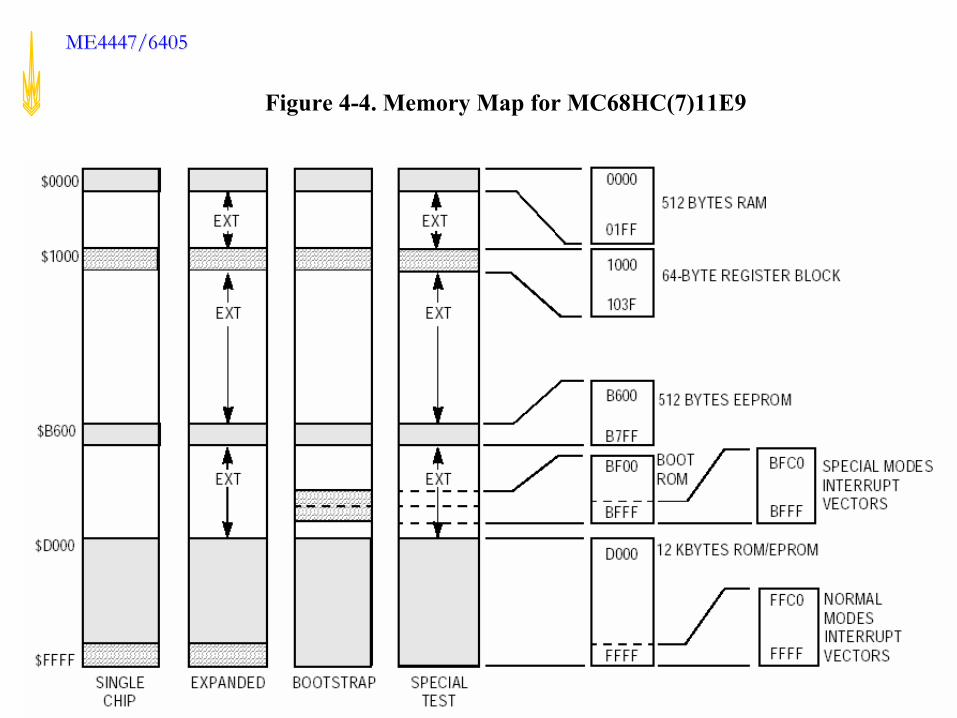
Figure 4-4. Memory Map for MC68HC(7)11E9
George W. Woodruff School of Mechanical Engineering, Georgia TechGeorge W. Woodruff School of Mechanical Engineering, Georgia Tech
ME4447/6405ME4447/6405

George W. Woodruff School of Mechanical Engineering, Georgia TechGeorge W. Woodruff School of Mechanical Engineering, Georgia Tech
ME4447/6405ME4447/6405
Axiom CME-11E9-EVBU Diagram (Axiom CME-11E9 Manual)
George W. Woodruff School of Mechanical Engineering, Georgia TechGeorge W. Woodruff School of Mechanical Engineering, Georgia Tech
ME4447/6405ME4447/6405
George W. Woodruff School of Mechanical Engineering, Georgia TechGeorge W. Woodruff School of Mechanical Engineering, Georgia Tech
ME4447/6405ME4447/6405 Axiom CME-11E9-EVBU Mode Select Jumpers
MODAPIN
5 V
GND
MODAJumper
10 K Ω
MODBPIN
5 V
GND
MODBJumper
10 K Ω
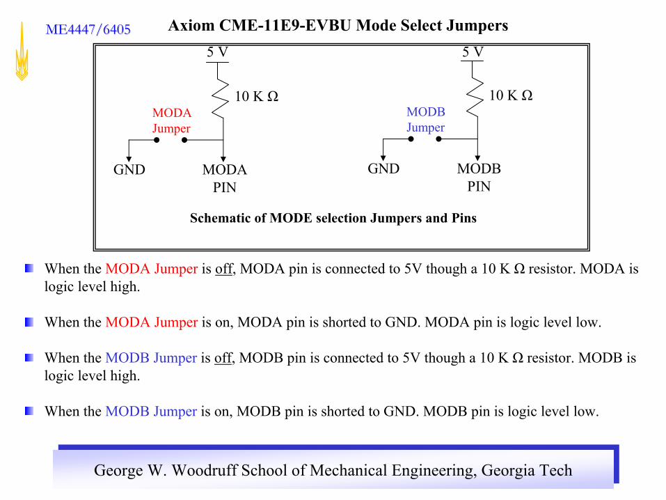
Schematic of MODE selection Jumpers and Pins
When the MODA Jumper is off, MODA pin is connected to 5V though a 10 K Ω resistor. MODA is logic level high.
When the MODA Jumper is on, MODA pin is shorted to GND. MODA pin is logic level low.
When the MODB Jumper is off, MODB pin is connected to 5V though a 10 K Ω resistor. MODB is logic level high.
When the MODB Jumper is on, MODB pin is shorted to GND. MODB pin is logic level low.

George W. Woodruff School of Mechanical Engineering, Georgia TechGeorge W. Woodruff School of Mechanical Engineering, Georgia Tech
ME4447/6405ME4447/6405
Special Test10OFFON
Bootstrap00ONON
Expanded11OFFOFF
Single chip01ONOFF
MODBLevel
MODALevel
MODB Jumper
MODA Jumper
Mode
MODA and MODB Logic Level at reset
Axiom CME-11E9-EVBU MODE SELECT JUMPERS
at reset
Axiom CME-11E9-EVBU Mode Select Summary

George W. Woodruff School of Mechanical Engineering, Georgia TechGeorge W. Woodruff School of Mechanical Engineering, Georgia Tech
ME4447/6405ME4447/6405Axiom CME-11E9-EVBUSingle chip mode
MODA Jumper ONMODB Jumper OFFJumpers located near 68HC11
Internal User Ram available:$0000-$002C$0100-$01FF
User can put a program in Internal EEPROM $B600-$BFFF and Internal User ram
Program in Internal EEPROMFirst 3 instructions of Buffalo checks if PE0 is high.If high then EEPROM instructions starting from $B600 are executed.Otherwise Buffalo will be loaded and can will be used to execute programs in Ram.
• Ports B and C available for use

George W. Woodruff School of Mechanical Engineering, Georgia TechGeorge W. Woodruff School of Mechanical Engineering, Georgia Tech
ME4447/6405ME4447/6405Axiom CME-11E9-EVBUExpanded modeROMON enabled
MODA Jumper OFFMODB Jumper OFFJumpers located near 68HC11
• Internal User Ram available:$0000-$002C$0100-$01FF
• User can put program in On-chip EEPROM $B600-$B7FF
• External User Ram$0200-$0FFF$1040-$7FFFUser can debug programs by loading them into Internal and External RAM by using Buffalo Monitor Program
• Mode used in Laboratory Assignments
• Port B and C not available for use
George W. Woodruff School of Mechanical Engineering, Georgia TechGeorge W. Woodruff School of Mechanical Engineering, Georgia Tech
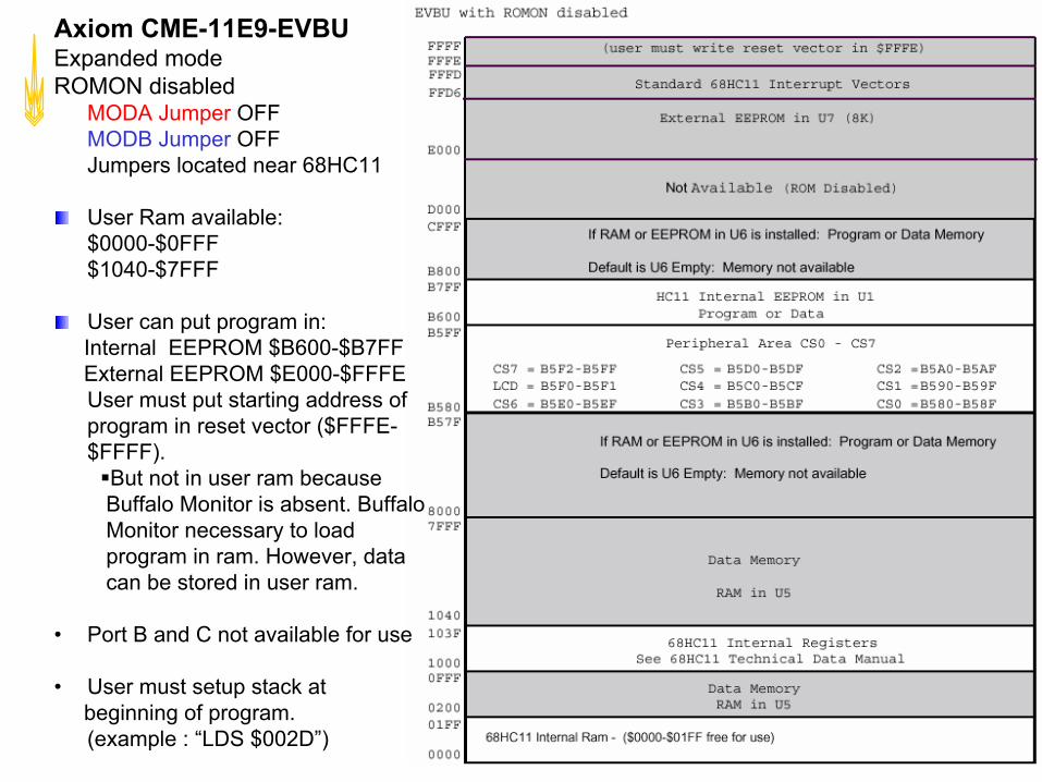
ME4447/6405ME4447/6405Axiom CME-11E9-EVBUExpanded modeROMON disabled
MODA Jumper OFFMODB Jumper OFFJumpers located near 68HC11
User Ram available:$0000-$0FFF$1040-$7FFF
User can put program in:Internal EEPROM $B600-$B7FFExternal EEPROM $E000-$FFFEUser must put starting address of program in reset vector ($FFFE-$FFFF).
But not in user ram because Buffalo Monitor is absent. Buffalo Monitor necessary to load program in ram. However, data can be stored in user ram.
• Port B and C not available for use
• User must setup stack atbeginning of program.(example : “LDS $002D”)

George W. Woodruff School of Mechanical Engineering, Georgia TechGeorge W. Woodruff School of Mechanical Engineering, Georgia Tech
ME4447/6405ME4447/6405
$FFFE-$FFFFRESET
$FFFC-$FFFD Clock monitor fail
$FFFA-$FFFB COP failure
$FFF8-$FFF9 Illegal opcode trap
$FFF6-$FFF7 Software interrupt
$FFF4-$FFF5 XIRQ pin
$FFF2-$FFF3 IRQ (external pin)
$FFF0-$FFF1 Real-time interrupt
$FFEE-$FFEF Timer input capture 1
$FFEC-$FFED Timer input capture 2
$FFEA-$FFEB Timer input capture 3
$FFE8-$FFE9 Timer output compare 1
$FFE6-$FFE7 Timer output compare 2
$FFE4-$FFE5 Timer output compare 3
$FFE2-$FFE3 Timer output compare 4
$FFE0-$FFE1 Timer input capture 4/output compare 5
$FFDE-$FFDF Timer overflow
$FFDC-$FFDD Pulse accumulator overflow
$FFDA-$FFDB Pulse accumulator input edge
$FFD8-$FFD9 SPI serial transfer complete
$FFD6-$FFD7 SCI serial system
Vector Interrupt
Interrupt Vector TableROMON disabled
Standard 68HC11 Interrupt Jump Table
Each vector is 2 bytes. User stores address of interrupt service routine in appropriate vector
Table 5-4. Interrupt and Reset Vector Assignments (Technical)
George W. Woodruff School of Mechanical Engineering, Georgia TechGeorge W. Woodruff School of Mechanical Engineering, Georgia Tech
ME4447/6405ME4447/6405
Standard 68HC11 Interrupt Jump Table (ROMON Disabled, ie No Buffalo Monitor)
The user can put the starting address of his/her subroutineDirectly in the vector field of the interrupt he/she wants toUse.
Example: If the user wants to use the IRQ interrupt, he/sheCan put the starting address of his/her subroutine directly inVector fields $FFF2 and $FFF3

George W. Woodruff School of Mechanical Engineering, Georgia TechGeorge W. Woodruff School of Mechanical Engineering, Georgia Tech
ME4447/6405ME4447/6405
$00FD - $00FFClock monitor fail
$00FA - $00FCCOP failure
$00F7 - $00F9Illegal opcode trap
$00F4 - $00F6Software interrupt
$00F1 - $00F3XIRQ pin
$00EE - $00F0IRQ (external pin)
$00EB - $00EDReal-time interrupt
$00E8 - $00EATimer input capture 1
$00E5 - $00E7Timer input capture 2
$00E2 - $00E4Timer input capture 3
$00DF - $00E1Timer output compare 1
$00DC - $00DETimer output compare 2
$00D9 - $00DBTimer output compare 3
$00D6 - $00D8Timer output compare 4
$00D3 - $00D5Timer input capture 4/output compare 5
$00D0 - $00D2Timer overflow
$00CD - $00CFPulse accumulator overflow
$00CA - $00CCPulse accumulator input edge
$00C7 - $00C9SPI serial transfer complete
$00C4 - $00C6SCI serial system
VectorInterruptInterrupt Vector TableROMON enabled
Standard 68HC11 Interrupt Vector Jump Table is not available with ROMON enabled because Buffalo Monitor Program cannot be overwritten
Buffalo Monitor Program supplies alternate Buffalo Monitor Interrupt Jump Table
Each Vector is 3 bytes. User writes jump instruction ($7E) in first byte and address of interrupt service routine in remaining two bytes
Table 4. Buffalo Monitor Interrupt Jump Table (EVBU Manual)

George W. Woodruff School of Mechanical Engineering, Georgia TechGeorge W. Woodruff School of Mechanical Engineering, Georgia Tech
ME4447/6405ME4447/6405
Using Buffalo Monitor Interrupt Jump Table (ie ROM Enabled)
To use Buffalo Monitor Interrupt Jump Table (EVBU Manual), the user must insert a jump opcode (extended) in the three byte field of the vector required. For an example, to use IRQ vector, with an and IRQ interrupt service routine located at $8000, the following is preformed:
a.Place $7E (JMP) at location $00EEb.Place IRQ interrupt service routine address at locations $00EF and $00F0.
$00EE 7E 80 00 JMP IRQ SERVICE
During initialization Buffalo checks the first byte of each set of three locations. If a $7E jump opcode is not found, Buffalo will install a jump to a routine called STOPIT. This assure there will be no uninitialized interrupt vectors which would cause undesirable operation. If an interrupt is accidentally encountered, the STOPIT routine will force a STOP instruction sequence to be executed. A user may replace any of the JMP STOPIT instructions with a JMP to a user written interrupt service routine
George W. Woodruff School of Mechanical Engineering, Georgia TechGeorge W. Woodruff School of Mechanical Engineering, Georgia Tech
ME4447/6405ME4447/6405
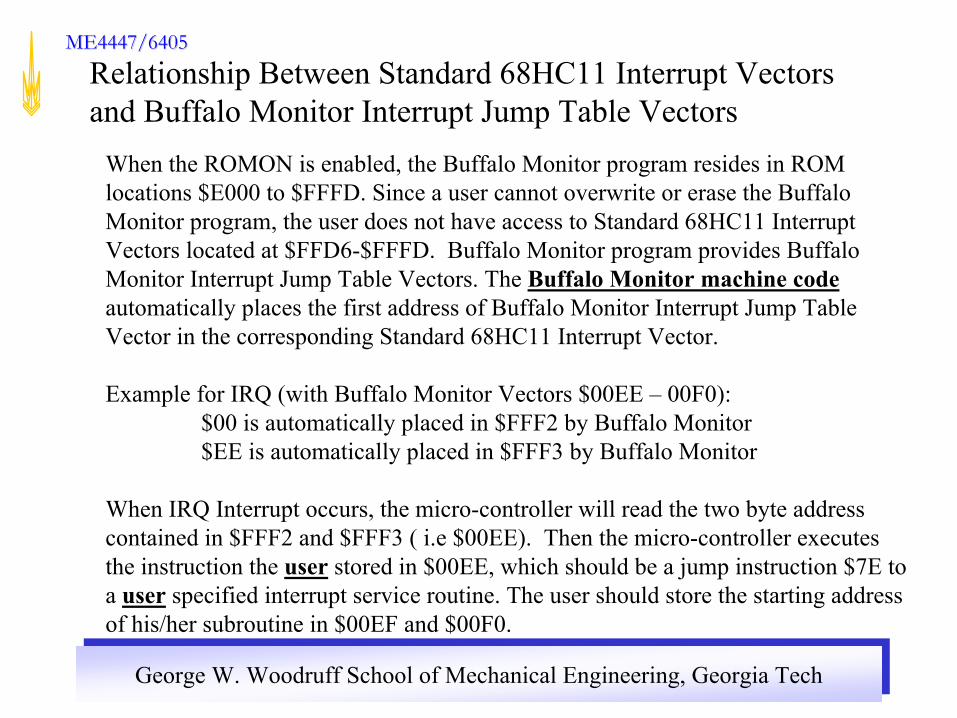
Relationship Between Standard 68HC11 Interrupt Vectors and Buffalo Monitor Interrupt Jump Table Vectors
When the ROMON is enabled, the Buffalo Monitor program resides in ROM locations $E000 to $FFFD. Since a user cannot overwrite or erase the Buffalo Monitor program, the user does not have access to Standard 68HC11 Interrupt Vectors located at $FFD6-$FFFD. Buffalo Monitor program provides Buffalo Monitor Interrupt Jump Table Vectors. The Buffalo Monitor machine codeautomatically places the first address of Buffalo Monitor Interrupt Jump Table Vector in the corresponding Standard 68HC11 Interrupt Vector.
Example for IRQ (with Buffalo Monitor Vectors $00EE – 00F0):$00 is automatically placed in $FFF2 by Buffalo Monitor$EE is automatically placed in $FFF3 by Buffalo Monitor
When IRQ Interrupt occurs, the micro-controller will read the two byte address contained in $FFF2 and $FFF3 ( i.e $00EE). Then the micro-controller executes the instruction the user stored in $00EE, which should be a jump instruction $7E to a user specified interrupt service routine. The user should store the starting address of his/her subroutine in $00EF and $00F0.

George W. Woodruff School of Mechanical Engineering, Georgia TechGeorge W. Woodruff School of Mechanical Engineering, Georgia Tech
ME4447/6405ME4447/6405
**************** EQUATES ****************RAMBS EQU $0000 start of ramREGBS EQU $1000 start of registersROMBS EQU $E000 start of romDSTREE EQU $B600 start of eepromDENDEE EQU $B7FF end of eepromPORTE EQU REGBS+$0A port eCFORC EQU REGBS+$0B force output compareTCNT EQU REGBS+$0E timer countTOC5 EQU REGBS+$1E oc5 regTCTL1 EQU REGBS+$20 timer control 1TMSK1 EQU REGBS+$22 timer mask 1TFLG1 EQU REGBS+$23 timer flag 1TMSK2 EQU REGBS+$24 timer mask 2BAUD EQU REGBS+$2B sci baud reg
Part of Buffalo Monitor Source code

George W. Woodruff School of Mechanical Engineering, Georgia TechGeorge W. Woodruff School of Mechanical Engineering, Georgia Tech
ME4447/6405ME4447/6405
SCCR1 EQU REGBS+$2C sci control1 regSCCR2 EQU REGBS+$2D sci control2 regSCSR EQU REGBS+$2E sci status regSCDAT EQU REGBS+$2F sci data regBPROT EQU REGBS+$35 block protect regOPTION EQU REGBS+$39 option regCOPRST EQU REGBS+$3A cop reset regPPROG EQU REGBS+$3B ee prog regHPRIO EQU REGBS+$3C hprio regCONFIG EQU REGBS+$3F config registerDFLOP EQU $4000 evb d flip flopDUART EQU $D000 duart addressPORTA EQU DUARTPORTB EQU DUART+8ACIA EQU $9800 acia addressPROMPT EQU '>'BUFFLNG EQU 35CTLA EQU $01 exit host or assemblerCTLB EQU $02 send break to hostCTLW EQU $17 waitCTLX EQU $18 abortDEL EQU $7F abortEOT EQU $04 end of text/tableSWI EQU $3F

George W. Woodruff School of Mechanical Engineering, Georgia TechGeorge W. Woodruff School of Mechanical Engineering, Georgia Tech
ME4447/6405ME4447/6405
**************** RAM ****************
ORG $2DRMB 20 user stack area
USTACK RMB 30 monitor stack areaSTACK RMB 1REGS RMB 9 user's pc,y,x,a,b,cSP RMB 2 user's spINBUFF RMB BUFFLNG input bufferENDBUFF EQU *COMBUFF RMB 8 command bufferSHFTREG RMB 2 input shift registerSTREE RMB 2 eeprom start addressENDEE RMB 2 eeprom end addressBRKTABL RMB 8 breakpoint tableAUTOLF RMB 1 auto lf flag for i/oIODEV RMB 1 0=sci, 1=acia, 2=duartA, 3=duartBEXTDEV RMB 1 0=none, 1=acia, 2=duart,HOSTDEV RMB 1 0=sci, 1=acia, 3=duartBCOUNT RMB 1 # characters readCHRCNT RMB 1 # characters output on current linePTRMEM RMB 2 current memory locationLDOFFST RMB 2 offset for download

George W. Woodruff School of Mechanical Engineering, Georgia TechGeorge W. Woodruff School of Mechanical Engineering, Georgia Tech
ME4447/6405ME4447/6405
*** Buffalo variables - used by: ***PTR0 RMB 2 main,readbuff,incbuff,ASPTR1 RMB 2 main,BR,DU,MO,AS,EXPTR2 RMB 2 EX,DU,MO,ASPTR3 RMB 2 EX,HO,MO,ASPTR4 RMB 2 EX,ASPTR5 RMB 2 EX,AS,BOOTPTR6 RMB 2 EX,AS,BOOTPTR7 RMB 2 EX,ASPTR8 RMB 2 ASTMP1 RMB 1 main,hexbin,buffarg,termargTMP2 RMB 1 GO,HO,AS,LOADTMP3 RMB 1 AS,LOADTMP4 RMB 1 TR,HO,ME,AS,LOAD*** Vector jump table ***JSCI RMB 3 At address $00C4JSPI RMB 3JPAIE RMB 3JPAO RMB 3JTOF RMB 3JTOC5 RMB 3JTOC4 RMB 3JTOC3 RMB 3JTOC2 RMB 3JTOC1 RMB 3

George W. Woodruff School of Mechanical Engineering, Georgia TechGeorge W. Woodruff School of Mechanical Engineering, Georgia Tech
ME4447/6405ME4447/6405
JTIC3 RMB 3JTIC2 RMB 3JTIC1 RMB 3JRTI RMB 3JIRQ RMB 3JXIRQ RMB 3JSWI RMB 3JILLOP RMB 3JCOP RMB 3JCLM RMB 3
George W. Woodruff School of Mechanical Engineering, Georgia TechGeorge W. Woodruff School of Mechanical Engineering, Georgia Tech
ME4447/6405ME4447/6405
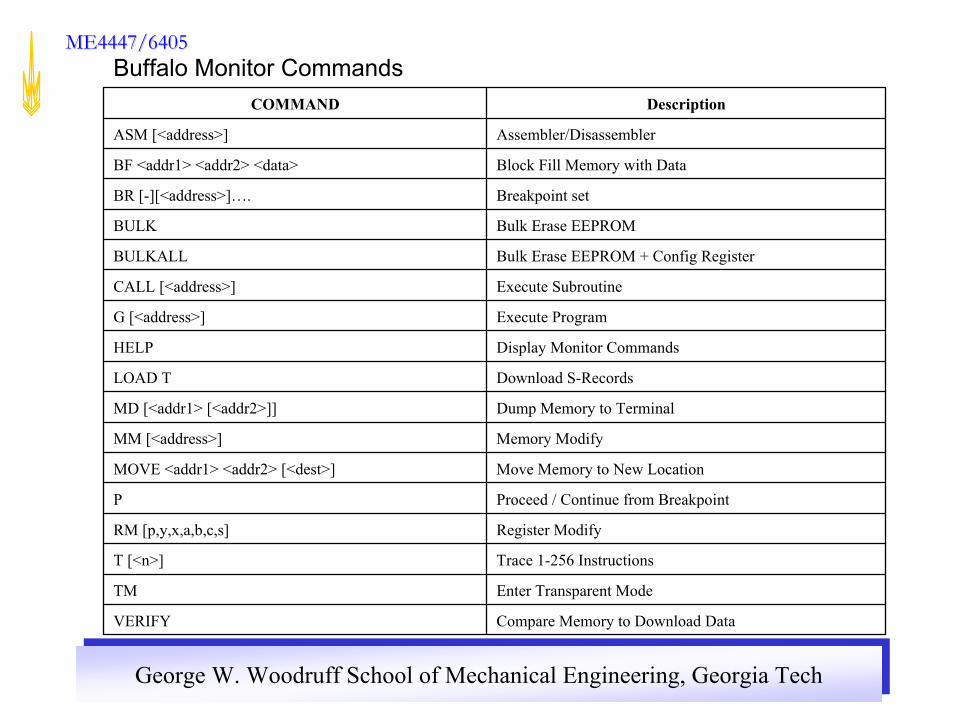
Compare Memory to Download DataVERIFY
Enter Transparent ModeTM
Trace 1-256 InstructionsT [<n>]
Register ModifyRM [p,y,x,a,b,c,s]
Proceed / Continue from BreakpointP
Move Memory to New LocationMOVE <addr1> <addr2> [<dest>]
Memory ModifyMM [<address>]
Dump Memory to TerminalMD [<addr1> [<addr2>]]
Download S-RecordsLOAD T
Display Monitor CommandsHELP
Execute ProgramG [<address>]
Execute SubroutineCALL [<address>]
Bulk Erase EEPROM + Config RegisterBULKALL
Bulk Erase EEPROMBULK
Breakpoint setBR [-][<address>]….
Block Fill Memory with DataBF <addr1> <addr2> <data>
Assembler/DisassemblerASM [<address>]
DescriptionCOMMAND
Buffalo Monitor Commands
George W. Woodruff School of Mechanical Engineering, Georgia TechGeorge W. Woodruff School of Mechanical Engineering, Georgia Tech
ME4447/6405ME4447/6405
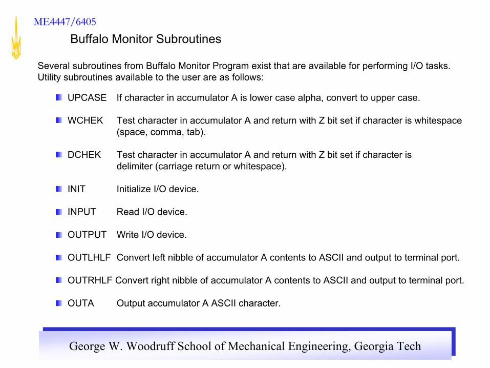
Several subroutines from Buffalo Monitor Program exist that are available for performing I/O tasks. Utility subroutines available to the user are as follows:
UPCASE If character in accumulator A is lower case alpha, convert to upper case.
WCHEK Test character in accumulator A and return with Z bit set if character is whitespace(space, comma, tab).
DCHEK Test character in accumulator A and return with Z bit set if character is delimiter (carriage return or whitespace).
INIT Initialize I/O device.
INPUT Read I/O device.
OUTPUT Write I/O device.
OUTLHLF Convert left nibble of accumulator A contents to ASCII and output to terminal port.
OUTRHLF Convert right nibble of accumulator A contents to ASCII and output to terminal port.
OUTA Output accumulator A ASCII character.
Buffalo Monitor Subroutines

George W. Woodruff School of Mechanical Engineering, Georgia TechGeorge W. Woodruff School of Mechanical Engineering, Georgia Tech
ME4447/6405ME4447/6405
OUTlBYT Convert binary byte at address in index register X to two ASCII characters and output. Returns address in index register X pointing to next byte.
OUTlBSP Convert binary byte at address in index register X to two ASCII characters and output followed by a space. Returns address in index register
OUT2BSP Convert two consecutive binary bytes starting at address in index register X to four ASCII characters and output followed by a space. Returns address in index register X pointing to next byte.
OUTCCRLF Output ASCII carriage return followed by a line feed.
OUTSTRG Output string of ASCII bytes pointed to by address in index register X until character is an end of transmission ($04).
OUTSTRGO Same as OUTSTRG except leading carriage return and line feed is skipped.
INCHAR Input ASCII character to accumulator A and echo back. This routine loops until character is actually received.

George W. Woodruff School of Mechanical Engineering, Georgia TechGeorge W. Woodruff School of Mechanical Engineering, Georgia Tech
ME4447/6405ME4447/6405
$FFAO JMP UPCASE Convert character to uppercase
$FFA3 JMP WCHEK Test character for whitespace
$FFA6 JMP DCHEK Check character for delimiter
$FFA9 JMP INIT Initialize I/O device
$FFAC JMP INPUT Read I/O device
$FFAF JMP OUTPUT Write I/O device
$FFB2 JMP OUTLHLF Convert left nibble to ASCII and output
$FFB5 JMP OUTRHLF Convert right nibble to ASCII and output
$FFB8 JMP OUTA Output ASCII character
To use an I/O subroutine, Jump Sub Routine (JSR) to the specified address listed below.
Example: “JSR $FFB8” to execute the OUTA subroutine

George W. Woodruff School of Mechanical Engineering, Georgia TechGeorge W. Woodruff School of Mechanical Engineering, Georgia Tech
ME4447/6405ME4447/6405
$FFBB JMP OUTlBYT Convert binary byte to 2 ASCII characters and output
$FFBE JMP OUT1BSP Convert binary byte to 2 ASCII characters and output followedby space
$FFCl JMP OUT2BSP Convert 2 consecutive binary bytes to 4 ASCII characters and output followed by space.
$FFC4 JMP OUTCRLF Output ASCII carriage return followed by line feed
$FFC7 JMP OUTSTRG Output ASCII string until end of transmission ($04)
$FFCA JMP OUTSTRGO Same as OUTSTRG except leading carriage return and line fees is skipped
$FFCD JMP INCHAR Input ASCII character and echo back