Embed Size (px)
Citation preview

ME 4447/6405Interrupts and Resets
Suzanne PriceScott Gilliliand
Greg Graf

Overview
Polling Interrupts Vector Tables Highest Priority Interrupt Register ADC Example with Interrupts Resets Standby Modes
Suzanne Price

Waiting for an Event : Polling
Program can “poll” for a value to change We saw this in our ADC lab:
Prevents processor from running other code We could not easily control LED’s while
checking the ATDC.
WATCH LDAA ATDSTAT1 ;Load the ADC registerANDA #$80 ;Get only the conversion complete flagBNE WATCH ;Loop if conversion is not complete
Suzanne Price

Waiting for an Event: Interrupts
User defined section of code that runs automatically when an event occurs Completion Flag Change in Pin Voltage Errors Others
Suspends main program execution while interrupt is serviced
Can happen at any time (when enabled) Maskable and Non-Maskable Interrupts
Suzanne Price

How Interrupts Work: Review
Event occurs Current instruction finishes If interrupts are enabled:
Push registers to stack Set interrupt bit(s) in CCR Run Interrupt Service Routine (ISR) until RTI Pull register values back from stack
Main program continues to run
Suzanne Price

Non-Maskable Interrupts
6 Non-Maskable Interrupts
Higher Priority than maskable interrupts
Can interrupt Maskable Interrupt ISRs
X=1 ONLY disables XIRQ interrupt (and all other interrupts are still enabled when X=1)
1. POR of RESET pin
2. Clock monitor reset
3. COP watchdog reset
4. Unimplemented instruction trap
5. Software interrupt (SWI)
6. XIRQ interrupt
Suzanne Price
Non-Maskable Interrupts
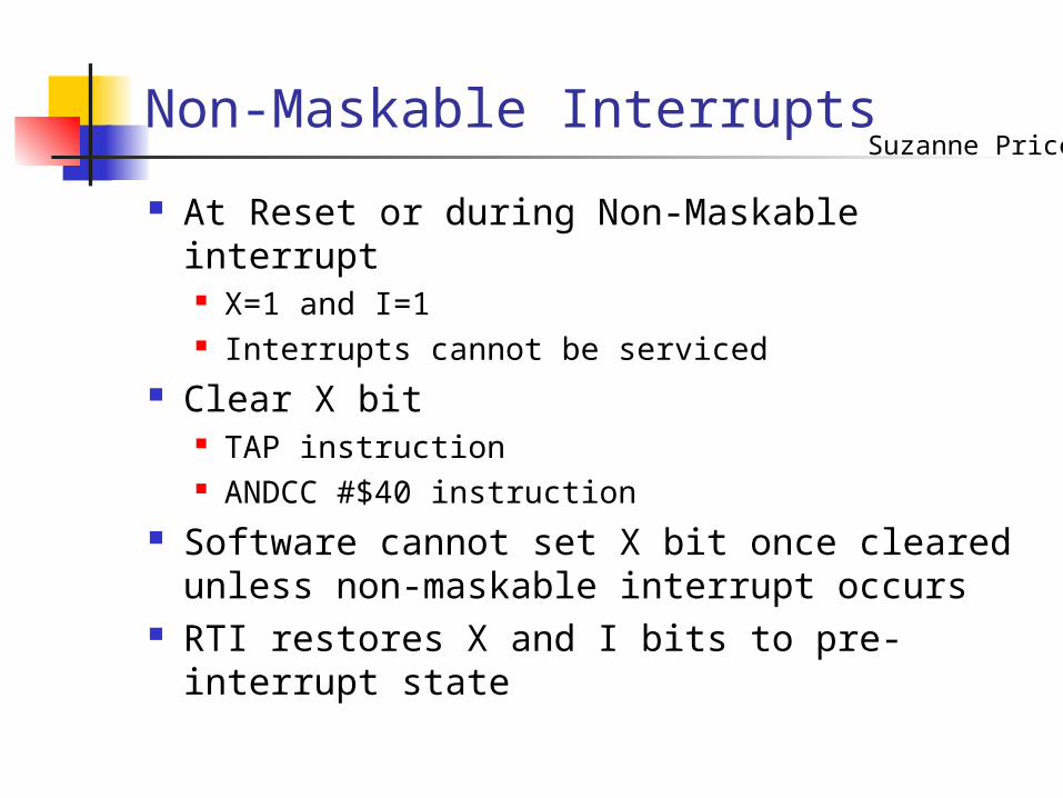
At Reset or during Non-Maskable interrupt X=1 and I=1 Interrupts cannot be serviced
Clear X bit TAP instruction ANDCC #$40 instruction
Software cannot set X bit once cleared unless non-maskable interrupt occurs
RTI restores X and I bits to pre-interrupt state
Suzanne Price

Non-Maskable Interrupts
XIRQ Externally triggered PE0 pin low = XIRQ interrupt
SWI Allows an interrupt without an event MON12 in use: jumps back to DBug12
Unimplemented Instruction Trap CPU is given code with invalid opcode Generates interrupt request to
unimplemented instruction trap vector
Suzanne Price

Maskable Interrupts
27 Maskable Interrupts Global Masking: controls
execution of all maskable interrupts (ie. I bit =1, no maskable interrupts occur)
Local Masking: controls execution of interrupt on a peripheral device (ie. ATD)
1. IRQ2. Real-Time Interrupt3. Standard Timer Channel 04. Standard Timer Channel 15. Standard Timer Channel 26. Standard Timer Channel 37. Standard Timer Channel 48. Standard Timer Channel 59. Standard Timer Channel 610. Standard Timer Channel 711. Standard Timer Overflow12. Pulse Accumulator A Overflow13. Pulse Accumulator Input Edge14. SPI transfer Complete15. SCI system16. ATD17. Port J18. CRG PLL Lock19. CRG Self Clock Mode20. Flash21. CAN Wakeup22. CAN Errors23. CAN Receive24. CAN Transmit25. Port P26. PWM Emergency Shutdown27. VREG LVI
Suzanne Price

Maskable Interrupts
IRQ Only external maskable interrupt signal IRQE bit on IRQCR Register
IRQE=1: Falling Edge Sensitive IRQE=0: Low Level-Sensitive
Peripheral Subsystems (all other Maskable Interrupts) Flag bit and interrupt enable bit ATD, Timers, PWM, serial communications,
etc.
Suzanne Price

Highest Priority Interrupt (HPRIO) Register
HPRIO register moves one maskable interrupt to top of priority list
Cannot change priority of non-maskable interrupts
Procedure to increase priority of maskable interrupt: Set I bit to disable maskable interrupts Write low byte of interrupt vector to HPRIO Clear I bit to re-enable maskable interrupts
Address: $001F
Suzanne Price

Highest Priority Interrupt Register (HPRIO)
Address: $001F
Bit 7 Bit 6 Bit 5 Bit 4 Bit 3 Bit 2 Bit 1 Bit 0
1 1 0 1 1 1 1
PSEL7 PSEL6 PSEL5 PSEL4 PSEL3 PSEL2 PSEL1 -
PSEL[7:1] – Priority Select Bits Selects one interrupts source to be elevated Can only be written while I-bit in the CCR is set and
maskable interrupts turned off Write the low byte of the maskable interrupt vector to
HPRIO to elevate that maskable interrupt to the highest priority
Ex: writing $DE to HPRIO elevates the Standard Timer Overflow to highest priority (Standard Timer Overflow vector = $FFDE)
Suzanne Price

Interrupt Vector: stores starting address of ISR
Interrupt Vector Table List of all
interrupt vectors used by processor
Stored at $FF00 - $FFFF
Interrupt Vector Table
MON12 and Interrupt Vector Tables
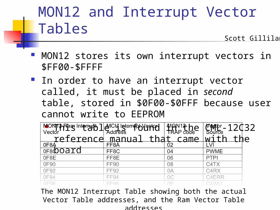
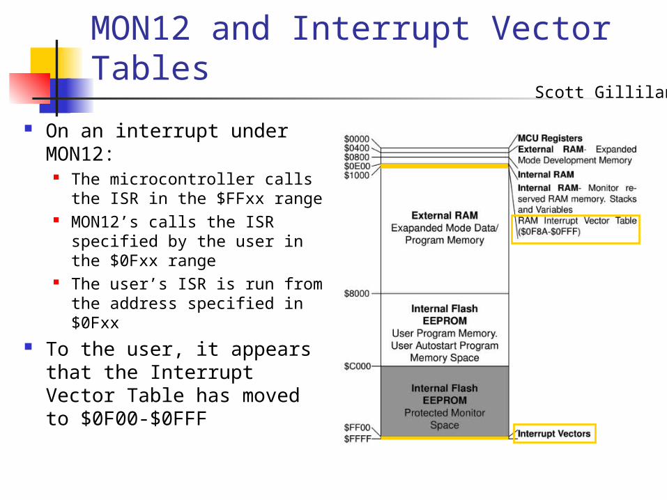
MON12 stores its own interrupt vectors in $FF00-$FFFF
In order to have an interrupt vector called, it must be placed in second table, stored in $0F00-$0FFF because user cannot write to EEPROM This table is found in the CML-12C32
reference manual that came with the board
The MON12 Interrupt Table showing both the actual Vector Table addresses, and the Ram Vector Table addresses
Scott Gilliland
MON12 and Interrupt Vector Tables
On an interrupt under MON12:
The microcontroller calls the ISR in the $FFxx range
MON12’s calls the ISR specified by the user in the $0Fxx range
The user’s ISR is run from the address specified in $0Fxx
To the user, it appears that the Interrupt Vector Table has moved to $0F00-$0FFF
Scott Gilliland

ADC Interrupt Example : ISR
Write an Interrupt Service Routine to be run whenever an ADC interrupt occurs
ISR stores latest value in memory for later use
Ensure that Sequence Complete Flag is cleared Needed to allow the next interrupt to
happen Write $80 to ATDSTAT0 to clear flag
Scott Gilliland

ADC Interrupt Example : ISR
*Interrupt Service Routine
ORG $2000LDAA ATDSTAT0LDAA ATDDR0HSTAA LSTCONV
LDAA #$80STAA ATDSTAT0RTI
Define a starting addressRead Status registerRead Result registerStore Value to a reserved memory location
Reset SFC flag by writing a ‘1’ to itEnsures that we will get the next interrupt
Finally, call RTI to return from the ISR and pull register values back from the stack
Scott Gilliland

ADC Interrupt Example: Setup
Set up Interrupt Vector Table for the ADC Interrupt Needs to be the address of the first
instruction of the ISR Set up ADC
Including ASCIE bit to enable ADC interrupts Enable global maskable interrupts Processor is now free to run other code Print the value stored into memory by
the ISR
Scott Gilliland

ADC Interrupt Example: Setup
ORG $1000SEILDX #$2000STX $0FD2
LDAA #%10000010STAA ATDCTL2LDAA #%10000101STAA ATDCTL4
LDY #41DELAY1 DEY
BNE DELAY1
CLI
Setup the ADC, including setting the ASCIE bit to enable local ADC interrupts
Set I bit to make Interrupt Vector Table changes safe
Store the address of our ISR ($2000) to the Interrupt Vector for the ADC ($0FD2)
Wait for the ADC to fully power up, and then clear the I-bit to enable all maskable interrupts
Scott Gilliland
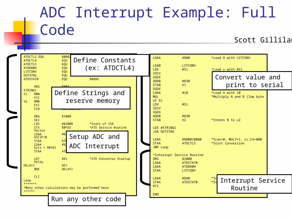
ADC Interrupt Example: Full Code
ATDCTL2 EQU $0082ATDCTL4 EQU $0084ATDCTL5 EQU $0085ATDDR0H EQU $0090LSTCONV EQU $800OUTSTRG EQU $FF5EATDSTAT0 EQU $0086
ORG $802STRING1 FCC "The voltage is "V1 RMB 1
FCC " . "V2 RMB 1
FCC " Volts"FCB $0A,$0D,$04
ORG $1000SEILDX #$2000 *Start of ISRSTX $0FD2 *ATD Service Routine VectorLDAA #%10000010 *ADPU = 1, ASCIE=1, ASCIF=0STAA ATDCTL2LDAA #%10000101 *SRES8=1, Prescaler bits = 00101STAA ATDCTL4
LDY #41 *STD Converter Startup Delay
DELAY1 DEYBNE DELAY1
CLILoop********Many other calculations may be performed here******
LDAA #$00 *Load D with LSTCONV
LDAB LSTCONVLDX #51 *Load x with #51IDIV *Divides D by X ->D:XXGDXADDB #$30STAB V1 *Stores B to v1 XGDXLDAA #10 *Load A with 10MUL *Multiply A and B (low byte of D)LDX #51IDIVXGDXADDB #$30STAB V2 *Stores B to v2
LDX #STRING1JSR OUTSTRG
LDAA #%00010000 *Scan=0, MULT=1, cc:CA=000STAA ATDCTL5 *Start ConversionJMP Loop
*Interrupt Service RoutineORG $2000LDAA ATDSTAT0LDAA ATDDR0HSTAA LSTCONV
LDAA #$80 *Scan=0, MULT=1, cc:CA=000STAA ATDSTAT0 *Start ConversionRTI
END
Define Constants(ex: ATDCTL4)
Define Strings and reserve memory
Setup ADC andADC Interrupt
Run any other code
Convert value and print to serial
Interrupt Service Routine
Scott Gilliland

Resets
Forces MCU to: Assume set of initial conditions Begin executing instructions at an assigned
starting address Like interrupts, resets have a vector to
define the starting address of code to be run
Unlike interrupts, they do not return to original code location
Resets have different vectors to allow execution of individualized code
Greg Graf
Resets: Process Flow
When a reset is triggered: The address from the vector is loaded
into the program counter S, X, and I bits are set in the CCR MCU hardware is initialized to reset
state Check for any interrupts that have
occurred
Greg Graf

Resets: POR, External, Low Power
Power on Reset (POR) Triggered when Vdd is applied Timing circuit is initialized, and allowed to settle for
4064 cycles External Reset (RESET)
Same vector as POR Reset pin must be pulled low for a total of 6 cycles
Low Power Reset Same vector as POR Triggered when Vdd drops below acceptable limit
Greg Graf

Resets: COP, Clock Monitor
Computer operating Properly (COP) Reset Protects against software failures (infinite loops, etc) When enabled (NOCOP bit in CONFIG register), resets
if free-running watchdog timer rolls over $FFFF Timer rate is set in the OPTION register. System E-
clock is divided by 215 and further scaled by 1, 2, or 4 Clock Monitor Reset
Protects against clock failure Set by CME control bit If enabled, system resets if no clock edges are
detected within a set period.
Greg Graf

Standby Modes
Suspends CPU operation until reset or interrupt occurs
Reduces power consumption CPU registers are stacked to speed up
recovery into interrupts Two modes: Wait, Stop
Greg Graf

Standby Modes: WAIT (WAI)
Suspends CPU Processing On-chip crystal oscillator remains active
Peripherals keep running Wait mode is exited through IRQ, XIRQ,
or any internally generated interrupts
Greg Graf

Standby Modes: Stop (STOP)
All clocks and peripherals stopped I/O pin levels remain static Stop is exited through external interrupts,
edge-triggered IRQ or RESET pin XIRQ always exits stop mode, but XIRQ
interrupts are only executed if X bit is clear Otherwise, code continues from STOP command
If S-bit in CCR is set, STOP is treated as NOP
Greg Graf

References
ME 4447/6405 Interrupts and Resets Lecture
HCS12 Reference Manuals
Appendix: Full Code ATDCTL2 EQU $0082 ATDCTL4 EQU $0084 ATDCTL5 EQU $0085 ATDDR0H EQU $0090 LSTCONV EQU $800 OUTSTRG EQU $FF5E ATDSTAT0 EQU $0086
ORG $802 STRING1 FCC "The voltage is " V1 RMB 1 FCC " . " V2 RMB 1
FCC " Volts" FCB $0A,$0D,$04
ORG $1000
SEI LDX #$2000 *Start of ISR STX $0FD2 *ATD Service Routine Vector
LDAA #%10000010 *ADPU = 1, ASCIE=1, ASCIF=0 STAA ATDCTL2 LDAA #%10000101 *SRES8=1, Prescaler bits = 00101 STAA ATDCTL4
LDY #41 *STD Converter Startup Delay DELAY1 DEY BNE DELAY1
CLI Loop
******* *Many other calculations may be performed here
******
LDAA #$00 *Load D with LSTCONV LDAB LSTCONV LDX #51 *Load x with #51 IDIV *Divides D by X. Stores remainder to D and the result in X XGDX ADDB #$30 STAB V1 *Stores B to v1 XGDX
LDAA #10 *Load A with 10 MUL *Multiply A and B (low byte of Remainder in D) LDX #51 IDIV XGDX ADDB #$30 STAB V2 *Stores B to v2
LDX #STRING1 JSR OUTSTRG
LDAA #%00010000 *Scan=0, MULT=1, cc:CA=000 STAA ATDCTL5 *Start Conversion JMP Loop
*Interrupt Service Routine ORG $2000 LDAA ATDSTAT0 LDAA ATDDR0H STAA LSTCONV
LDAA #$80 *Scan=0, MULT=1, cc:CA=000 STAA ATDSTAT0 *Start Conversion RTI
End

Interrupt Flow
Interrupt conditionis met
Restore Registersw/ org. Values
Standard InterruptTable
Analyze Priority
Store all registerson the Stack
Global Masking
Local Masking
ContinueProgram
Complete CurrentInstruction
A
Set (I) or (X) to prohibit another
Interrupt
Load Address inappropriate vector
YES
NO
NO
YES
ISR instruction
Clear I or X bit inCCR
RTI
YES
NO
B
B
A
Note: Local mask must be cleared prior to performing RTI