Embed Size (px)
Citation preview

ME 330Manufacturing Processes
WELDING PROCESSES(cont.)

Principle of the process
Structure and configuration
Process modeling
Defects
Design For Manufacturing (DFM)
Process variation

Weld Joints: Five Types
(a) Butt joint, (b) corner joint, (c) lap joint, (d) tee joint, and (e) edge joint
(a) Inside single fillet corner joint;
(b) outside single fillet corner joint;
(c) double fillet lap joint;
(d) double fillet tee joint
Weld Types: Fillet Welds
Filler metal is used

©2010 John Wiley & Sons, Inc. M P Groover, Fundamentals of Modern Manufacturing 4/e
(a) square groove weld;
(b) single bevel groove weld;
(c) single V‑groove weld;
(d) single U‑groove weld;
(e) single J‑groove weld;
(f) double V‑groove weld (for thicker sections)
Weld Types: Groove Welds
Filler metal is used

Weld Types: Plug Weld and Slot Weld
(a) Plug weld and (b) slot weld
Filler metal is used

Fused section between surfaces of two sheets or plates:
(a) spot weld and (b) seam weld Used for lap joints Used commonly with resistance welding No filler metal
Weld Types: Spot Weld and Seam Weld

Weld Types: Flange Weld and Surfacing Weld
(a) Flange weld;
(b) Surfacing weld used not to join parts but to deposit filler metal onto surface of a base part

Principle of the process
Structure and configuration
Process modeling
Defects / quality control
Design For Manufacturing (DFM)
Process variation

Cross section of a typical fusion welded joint:
(a) principal zones in the joint, and (b) typical grain structure
Typical Fusion Welded Joint
Weld Quality
Motivation:
Obtaining a weld joint that is strong and absent of defects
Topics:
1. Residual stresses and distortion
2. Welding defects
3. Inspection and testing methods

Residual Stresses and Distortion
Principle: Rapid heating and cooling in localized regions during fusion welding result in thermal expansion and contraction that cause residual stresses, and stresses cause distortion and warpage
Butt welding
Shrinkage
Residual stress warping of weldment

Techniques to Minimize Warpage
Welding fixtures to physically restrain parts
Heat sinks to rapidly remove heat
Tack welding at multiple points along joint to create a rigid structure prior to seam welding
Selection of welding conditions (speed, amount of filler metal used, etc.) to reduce warpage
Preheating base parts
Stress relief heat treatment of welded assembly
Proper design of weldment

Welding cracks: On weld or near weld Very serious because strength is reduced significantly Caused by low of weld and/or base metal combined with high
stresses during contraction
Weld Defects: Welding Cracks

Welding Defects: Cavities
Two defect types:
1. Porosity - small voids in weld metal formed by gases entrapped during solidification, caused by inclusion of atmospheric gases, sulfur in weld metal, or surface contaminants
2. Shrinkage voids - cavities formed by shrinkage during solidification
Welding Defects: Solid Inclusions
Nonmetallic material entrapped in weld metal:
1. Most common form is generated during arc welding processes that use flux. Instead of floating to top of weld pool, globules of slag become encased during solidification
2. Other forms: formation of metallic oxides, such as Al2O3
when welding aluminum

A weld bead in which fusion has not occurred throughout entire cross section of joint. Forms of incomplete fusion are shown below:
Welding Defects: Incomplete Fusion
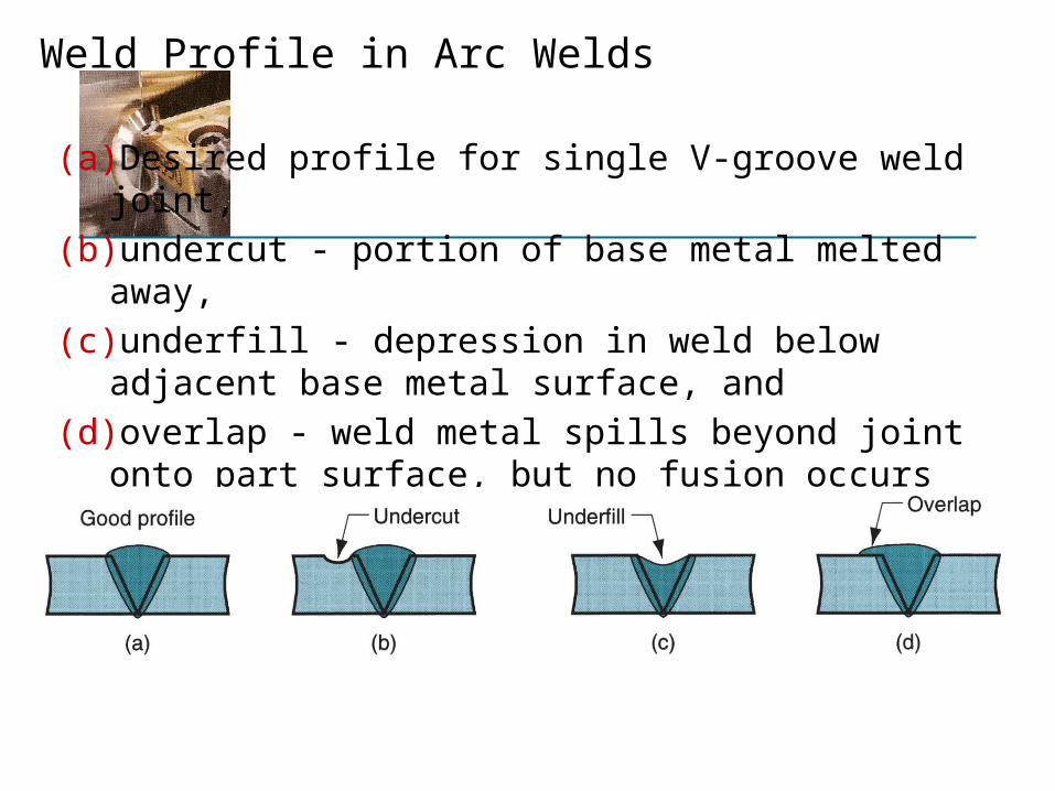
(a) Desired profile for single V-groove weld joint,
(b) undercut - portion of base metal melted away,
(c) underfill - depression in weld below adjacent base metal surface, and
(d) overlap - weld metal spills beyond joint onto part surface, but no fusion occurs
Weld Profile in Arc Welds

Inspection and Testing Methods: Visual Inspection
Most widely used welding inspection method is manual examination for:
1. Conformance to dimensions, warpage 2. Surface defects, such as cracks, cavities,
incomplete fusion
Limitations: Only surface defects are detectable

Inspection and Testing Methods:Nondestructive Evaluation (NDE) Tests
1. Ultrasonic testing - high frequency sound waves through specimen to detect cracks and inclusions
2. Radiographic testing - x‑rays or gamma radiation provide photographs of internal flaws
3. Dye‑penetrant and fluorescent‑penetrant tests - to detect small cracks and cavities at part surface
4. Magnetic particle testing – iron filings sprinkled on surface reveal subsurface defects that distort the magnetic field
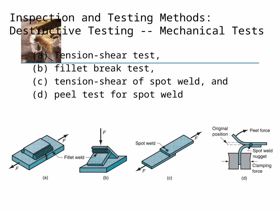
Inspection and Testing Methods:Destructive Testing -- Mechanical Tests
(a) Tension-shear test,
(b) fillet break test,
(c) tension-shear of spot weld, and
(d) peel test for spot weld

Inspection and Testing Methods:Destructive Testing -- Metallurgical Tests
Metallurgical tests – to examine metallic structure, defects, extent and condition of heat affected zone, presence of other elements, etc. of the weldment Microscopy is an example of this

Weldability
Capacity of a metal or combination of metals to be welded into a suitable structure, and
For the resulting weld joint(s) to possess the required metallurgical properties to perform satisfactorily in intended service
Good weldability characterized by
1. Ease with which welding is accomplished
2. Absence of weld defects
3. Strength, ductility, and toughness in welded joint

Weldability Factors: Welding Process
Some metals or metal combinations can be readily welded by one process but are difficult to weld by others
Example: stainless steel readily welded by most arc welding and resistance welding processes, but difficult to weld by oxyfuel welding

Weldability Factors: Base Metal
1. Some metals melt too easily; e.g., aluminum
2. Metals with high thermal conductivity transfer heat away
from weld, which causes problems; e.g., copper
3. High thermal expansion and contraction in metal causes
distortion problems
4. Dissimilar metals pose problems in welding when their
physical and/or mechanical properties are substantially
different

Other Factors Affecting Weldability
Filler metal. Must be compatible with base metal(s)
Surface conditions (how clean)
1. Moisture can result in porosity in fusion zone
2. Oxides and other films on metal surfaces can prevent adequate contact and fusion

Principle of the process
Structure and configuration
Process modeling
Defects
Design For Manufacturing (DFM)
Process variation

Design Considerations in Welding
Minimum parts ‑ welded assemblies should consist of fewest number of parts possible
Example: usually more cost efficient to perform simple bending operations on a part than to weld an assembly from flat plates and sheets
Design assembly to allow for welding gun access
Assembly should allow for welding from above