Embed Size (px)
Citation preview

MDG Technologies
Using Sparx Systems Enterprise Architect, you can create models based on UML or ModelDriven Generation (MDG) Technologies that are supplied with the system, or from external
locations, or developed with Enterprise Architect in your own organization.
Enterprise Architect
User Guide Series
Author: Sparx Systems
Date: 2020-01-20
Version: 15.1
CREATED WITH

Table of Contents
MDG Technologies 5Specify Required MDG Technologies 6Work with MDG Technologies 8Manage MDG Technologies 9Access Remote MDG Technologies 11Import MDG Technologies to Model 12Extensions - MDG Technologies 14MDG Technology SDK 16
Defining a Modeling Language 17Developing Profiles 19
Create Stereotype Profiles 20Create a Profile Package 22Add Stereotypes and Metaclasses 24Create Stereotypes Extending non-UML Objects 27
Redefine Stereotypes in Another Profile 29Define Stereotype Tagged Values 31
Add an Enumeration to a Stereotype 32Define a Structured Tagged Value 34Use the Tagged Value Connector 37With Predefined Tag Types 38
Define Stereotype Constraints 39Add Shape Scripts 40Set Default Appearance 42Special Attributes 43
Define a Stereotype as a Metatype 48Define Multiple-Stereotype Level 49Define Creation of Instance 50Define Composite Elements 51Define Child Diagram Type 52Define Tag Groupings 54
Introducing the Metamodel Views 56Built-in Metamodel Diagram View 58Custom Metamodel Diagram View 62Define Metamodel Constraints 68
Constraints on Meta-Constraint connector 73Quick Linker 80
Quick Linker Definition Format 81Relationship Table 85Quick Linker Example 87Hide Default Quick Linker Settings 89Quick Linker Object Names 90Add Quick Linker Definition To Profile 93
Export a Profile 94Save Profile Options 96
UML Profiles in the Resources Window 97Import UML Profiles Into the Resources Window 98
MDG Technologies - Creating 99
Using the Profile Helpers 100Create Stereotype Profiles using Profile Helpers 102
Add Stereotypes and Metaclasses using Profile Helpers 104Edit a Stereotype Element 107
Create Diagram Profiles using the Profile Helpers 108Create Toolbox Profiles using the Profile Helpers 110
Create Hidden Sub-Menus using the Profile Helpers 114Create MDG Technology File 116
Add a Profile 118Add a Pattern 119Add a Diagram Profile 120Add a Toolbox Profile 121Add Tagged Value Types 122Add Code Modules 123
Define Code Options 124Add MDA Transforms 126Add Document Report Templates 127Add Linked Document Templates 128Add Images 129Add Scripts 130Add Workspace Layouts 131Add Model Views 132Add Model Searches 133
Working with MTS Files 134Create Toolbox Profiles 135
Create Toolbox Profiles 136Toolbox Page Attributes 139
Create Hidden Sub-Menus 140Assign Icons To Toolbox Items 142Override Default Toolboxes 144Elements Used in Toolboxes 146Connectors Used in Toolboxes 149
Create Custom Diagram Profiles 151Built-In Diagram Types 153Attribute Values - styleex & pdata 154
Set Up Technology Element Images 156Define Validation Configuration 158Incorporate Model Wizard Templates 159Add Import/Export Scripts 161Deploy An MDG Technology 163
Shape Scripts 164Getting Started With Shape Scripts 165Shape Editor 167Write Scripts 168
Shape Attributes 171Drawing Methods 174Color Queries 181Conditional Branching 182Query Methods 183Display Element/Connector Properties 186Sub-Shapes 190

Add Custom Compartments to Element 192Show Composite Diagram 197Reserved Names 201Syntax Grammar 203
Example Scripts 205Tagged Value Types 215
Create Tagged Value Type from Predefined Types 216Predefined Structured Types 217Create Custom Masked Tagged Value Type 223Create Reference Data Tagged Values 225Predefined Reference Data Types 226

MDG Technologies - MDG Technologies 20 January, 2020
MDG Technologies
An MDG Technology is a vehicle for providing access to the resources of either a commercially-available technology ora technology that you have created yourself. Such resources include a wide range of facilities and tools, such as UMLProfiles, code modules, scripts, Patterns, images, Tagged Value Types, report templates, Linked Document templates andToolbox pages.
Using Enterprise Architect, you can develop models based on the standard UML specifications, and you can extend thecore UML structures using UML-supported mechanisms such as Tagged Values, Stereotypes, Profiles and DesignPatterns. These facilities are within the Enterprise Architect core technologies, and you can activate and use furtherModel Driven Generation (MDG) Technologies that are either integrated with the system or available from externallocations.
If your systems or work domain require further specialization you, as a Technology Developer, can use EnterpriseArchitect to develop your own customized modeling languages and solutions.
Obtain and use Technologies
Source of Technology
Core technologies - Enterprise Architect itself contains a:
Basic UML 2 technology as an implementation of UML 2.5 structural and behavioral modeling, and·
Core Extensions technology that applies profiles and stereotypes to provide extended modeling of aspects such·as Requirements, User interface and Data Modeling
Additional technologies are included in the Enterprise Architect Install directory, MDGTechnologies subfolder.
You can import technologies from external sources into the APPDATA folder (%APPDATA%\SparxSystems\EA\MDGTechnologies) for your own use, or into the Resources window for other project users to access.
You can transfer technologies into the MDGTechnologies subfolder; these technologies are available when yourestart Enterprise Architect (on Vista/Windows 7 systems you might have to increase your access permissions to dothis).
You can access and activate MDG Technologies in remote system folders or web sites, from Enterprise Architect.
Technology Developers can create new MDG Technologies and deploy them to the project team either through theMDGTechnologies subfolder or from a remote folder or website.
To see which technologies are available within Enterprise Architect, and activate the ones you require, use the'MDG Technologies' dialog ('Specialize > Technologies > Manage-Tech' ribbon option).
Having made the MDG Technologies available, you can manage their availability to users and you can work withthem.
You also have the facility to turn off or disable the Enterprise Architect 'Basic UML 2' and 'Core Extensions'technologies and facilities, so that you can apply the Enterprise Architect facilities and features exclusively to one ormore selected MDG Technologies.
(c) Sparx Systems 2019 Page 5 of 228 Created with Enterprise Architect

MDG Technologies - MDG Technologies 20 January, 2020
Specify Required MDG Technologies
When you have a model that must make use of certain MDG Technologies, a model Administrator can configure thesystem to check that those Technologies are available and active during the loading process, before the model actuallyopens. You identify the Technologies in the 'MDG Technologies' section of the 'Manage Project Options' dialog. If aTechnology is:
Required and not installed on a user's machine, that user will be unable to open the model·
Required and available, but not enabled, the system can be configured to automatically enable that Technology·
Specifically not to be used in this model, but is available and enabled, the system can be configured to automatically·disable that Technology
The model Administrator can thus ensure that the correct operating environment is in place to work in the model, so thatall users have the same view and are using the same facilities (or, at least, are not using the wrong tools and creatingstructures that other users cannot work with).
You could have a 'relaxed' model where some Technologies are required but others can be used at the user's discretion, ora 'restricted' model where certain Technologies are required and all others are blocked.
Access
Ribbon Configure > Model > Options > MDG Technologies
Select Required Technologies
Option Action
Technology Review the MDG Technologies currently accessible to you, listed in alphabeticalorder. These technologies might be built-in to Enterprise Architect, provided by anAdd-In or from an imported directory or URL.
Required For a model Administrator, select this checkbox against each Technology that mustbe available before the model can be opened.
Next time a user tries to open the model, Enterprise Architect will check that theselected Technologies are available on the user's system before allowing access tothe model. If a required Technology is not installed, Enterprise Architect will notopen the model.
Additionally, if a Technology flagged as Required is available but not enabled, thesystem will automatically enable it for this model; the Technology will still bedisabled in any other models the user might access.
Disabled All checkboxes default to unselected, allowing the Technologies to be used.
Select the checkbox against each Technology that specifically must not be used inthe model. If the Technology is available and enabled, the system automaticallydisables it within the model. It will still be enabled in other models that the usermight access.
All Click on this button to select the 'Required' checkbox of every Technology in thelist.
(c) Sparx Systems 2019 Page 6 of 228 Created with Enterprise Architect

MDG Technologies - MDG Technologies 20 January, 2020
None Click on this button to clear all selected 'Required' checkboxes in the list.
Notes
In the Corporate, Unified and Ultimate editions of Enterprise Architect, if security is enabled you must have·'Configure Project Requisites' permission to select or clear the 'Required' and 'Disabled' checkboxes against theTechnologies
(c) Sparx Systems 2019 Page 7 of 228 Created with Enterprise Architect

MDG Technologies - MDG Technologies 20 January, 2020
Work with MDG Technologies
Any MDG Technology listed on the 'MDG Technologies' dialog can be enabled, which makes their interface profiles andToolbox pages available for your use.
When you enable an MDG Technology, any Technology-specific diagram types are added to the 'New Diagram' dialoglists, and the Technology's Diagram Toolbox pages are added to those available through the search facilities of theToolbox.
If you set an MDG Technology to 'Active', it becomes the main technology for the model. Only one Technology can beactive at a time. The Technology's validation configuration is set, and whilst common Toolbox pages are visible at alltimes, the Technology's Toolbox pages override any parallel Enterprise Architect Toolbox pages; for example, theICONIX 'Class' pages would override the Enterprise Architect 'Class' pages.
You create Technology-specific diagrams and populate them with elements and connectors in the same way as forstandard Enterprise Architect diagrams.
(c) Sparx Systems 2019 Page 8 of 228 Created with Enterprise Architect

MDG Technologies - MDG Technologies 20 January, 2020
Manage MDG Technologies
You use the 'Manage MDG Technologies' dialog to manage the MDG Technologies accessible to the project andavailable to project users. The dialog lists the technologies held in a number of locations accessed by the project, such asthe APPDATA folder and the Enterprise Architect Install directory. You can set these technologies to being available foruse or disabled, as you require. MDG Technologies are deployed as .xml files.
Access
Ribbon Specialize > Technologies > Manage
Configure availability of Technologies
Option Action
Technology Lists all MDG Technologies currently accessible to the project, in alphabeticalorder.
If you click on a Technology name, the upper right panel of the dialog displays thetechnology:
Name·
Version number·
Logo (if defined), and·
Location of the deployed XML file, which can be:· - Internal to Enterprise Architect - An extension - In the Install directory (just the file name) - In the APPDATA folder (filename followed by (in APPDATA)) - In the model
The lower right panel displays a description of the Technology, in many casesproviding the manufacturer's web site address and a support contact.
Enabled Select this checkbox against each Technology that you want to be available for usein the project. When an MDG Technology is enabled:
The Technology is added to the list of available options in the 'Profile' field of·the Default Tools toolbar, so that you can apply the interface profiles of theMDG Technology
At least one set of Toolbox pages for the MDG Technology is automatically·added to the Diagram Toolbox; you can access the added Toolbox pagesthrough the 'Find Toolbox Item' dialog
Any MDG Technology-specific diagram templates are added to the 'New·Diagram' dialog for selection; when selected, these display thediagram-specific Toolbox pages
Clear the checkbox against a Technology to make it unavailable to the projectusers.
If you disable an MDG Technology that was in use, its Toolbox pages, diagramtypes and quick-links are omitted from the Diagram Toolbox, Default Tools
(c) Sparx Systems 2019 Page 9 of 228 Created with Enterprise Architect

MDG Technologies - MDG Technologies 20 January, 2020
toolbar, diagrams and 'New Diagram' dialog in the user interface.
All Click on this button to select the 'Enabled' checkbox of every Technology listed onthe dialog.
None Click on this button to clear the 'Enabled' checkbox of every Technology listed onthe dialog.
If you click on this button, scroll to the top of the list and select the 'Basic UML 2Technology' and 'Core Extensions' checkboxes to re-enable the 'UML' and'Extended' Toolbox pages and diagram types.
Set Active Setting a Technology to Active makes that Technology your default interface toEnterprise Architect, and can:
Override various Toolbox pages (including those from other Technologies)·with pages specific to the active Technology
Redefine a stereotype in another profile, adding new tags and removing or·modifying existing tags, while the stereotype behaves in all other ways as if itis the original stereotype
If your preferred Technology does not use overrides and redefinitions, it is notnecessary to set it to Active.
Select and highlight your preferred Technology, then click on the Set Active button.This displays an asterisk against the Technology name in the 'Technology' panel,and selects the Technology in the 'Profile' field of the Default Tools toolbar. If theMDG Technology has not yet been enabled, this button also enables it.
Advanced Click on this button to add MDG Technologies in folders and websites remote fromEnterprise Architect.
Remove (Enabled only for Technologies imported directly into the model.)
Click on this button to remove the selected Technology from the list, from theResources window and from the model.
OK Click on this button to close the dialog, save your changes and put them into effect.
Cancel Click on this button to close the dialog and abort the changes you have made.
Notes
If you change the 'Enabled' setting of an MDG Technology, or if you change the list of external paths, click on the·OK button to reload all enabled technologies; you do not need to restart Enterprise Architect for the changes to takeeffect
To work exclusively in a selected MDG Technology, or a small number of Technologies, you can enable just those·Technologies (and perhaps set one of them to Active) and then deselect the 'Basic UML 2 Technology' checkbox(and, if necessary, the 'Core Extensions' checkbox)
(c) Sparx Systems 2019 Page 10 of 228 Created with Enterprise Architect

MDG Technologies - MDG Technologies 20 January, 2020
Access Remote MDG Technologies
When you are working on your model, you can use MDG Technologies local to your system, or you can accessTechnologies you have identified in folders and websites remote from the system. You essentially 'bookmark' theseremote Technologies for continued use, and then delete the link when you do not want to use them any more.
Access
Ribbon Specialize > Technologies > Manage-Tech : Advanced
Notes
To remove an MDG Technology listed in the 'MDG Technologies - Advanced' dialog, click on the folder path or·URL and click on the Remove button; the path or URL is deleted
Specify the location of a remote MDG Technology
Step Action
1 On the 'MDG Technologies - Advanced' dialog, click on the Add button.
A short context menu displays, offering the options:
'Add Path'·
'Add URL'·
2 To specify an MDG Technology in a directory folder, select the 'Add Path' option.
The 'Browse for Folder' dialog displays.
Browse for the MDG Technology folder, click on it, and click on the OK button; go to step 4.
3 To specify an MDG Technology on a web site, select the 'Add URL' option.
The 'Input' dialog displays.
In the 'Enter Value' field, type or copy-and-paste the MDG Technology URL and click on the OK button.
4 The folder path or URL for the MDG Technology displays in the Path panel.
The Technology is available
(c) Sparx Systems 2019 Page 11 of 228 Created with Enterprise Architect

MDG Technologies - MDG Technologies 20 January, 2020
Import MDG Technologies to Model
If you locate or create an MDG Technology that is of use to your project, you can import it into the project either:
For only your own use; that is, import the technology into the %APPDATA%\Sparx·Systems\EA\MDGTechnologies folder on your workstation, or
To be available to all users of the model, through the Resources window for the model·
To import an MDG Technology you must have a suitable MDG Technology XML file. If the MDG Technology includesreferences to any metafiles, they should be in the same directory as the MDG Technology XML file.
The Model Patterns provided with the MDG Technology must each have the relevant Pattern XML file, and an RTF filewith the same file name containing a description of the Pattern, in the ModelPatterns directory within the EnterpriseArchitect install directory.
On start up, Enterprise Architect scans both the APPDATA folder and the Enterprise Architect Install directoryMDGTechnologies subfolder for technology files, to make them available through the 'MDG Technologies' dialog and,for model Technologies, the Resources window. Technologies imported to the APPDATA folder are indicated by thetext 'Location: Technology.xml'. The Model Patterns have to be imported into the ModelPatterns directory on the user'ssystem separately.
Access
Ribbon Specialize > Technologies > Publish-Tech > Import MDG Technology
Context Menu In the Resources window | Right-click MDG Technologies folder | ImportTechnology
Import a technology
Step Action
1 On the 'Import MDG Technology' dialog, in the 'Filename' field, type the path and filename of the MDG
Technology file to import, or browse for it using the button.
When you enter the filename, the MDG Technology name and version display in the 'Technology' and'Version' fields, and any notes display in the 'Notes' field.
2 Select the appropriate radio button for the type of import you want to perform:
Import to Model·
Import to User·
3 Click on the OK button.
(If you selected the 'Import to User' option) If the APPDATA folder does not yet exist, Enterprise·Architect creates it
If the MDG Technology already exists, Enterprise Architect displays a prompt to overwrite the·existing version and import the new one
Once the import to APPDATA is complete, you must restart Enterprise Architect; the MDG Technologyis then listed in the 'MDG Technologies' dialog.
(c) Sparx Systems 2019 Page 12 of 228 Created with Enterprise Architect

MDG Technologies - MDG Technologies 20 January, 2020
Notes
To remove an MDG Technology that has been added to APPDATA, locate the appropriate XML file in the·%APPDATA%\Sparx Systems\EA\MDGTechnologies folder and delete it
Consider the fact that some MDG Technologies can be large and might impose some delays on the workstation as·they load each time a user connects to the model
To remove an MDG Technology from the Resources window and the model, either:· - Right-click on the Technology name and select the 'Remove Technology' menu option, or - Click on the Technology name in the 'Manage MDG Technologies' dialog and click on the Remove button
(c) Sparx Systems 2019 Page 13 of 228 Created with Enterprise Architect

MDG Technologies - MDG Technologies 20 January, 2020
Extensions - MDG Technologies
Enterprise Architect is the core for a range of Model Driven Generation (MDG) extensions to its modeling capabilities,using more specialized, niche frameworks and profiles.
Extension Facilities
Extensions
A number of technologies are already integrated with the Enterprise Architect installer, including:
ArchiMate·
BPEL·
BPMN·
Data Flow diagrams·
Eriksson-Penker Extensions·
ICONIX·
Mind Mapping·
SoaML·
SOMF 2.1·
Strategic Modeling·
Systems Modeling Language (SysML)·
MDG Link For Eclipse·
MDG Link For Visual Studio.NET·
Enterprise Architect provides support for:
Downloading MDG Technologies from external system files or websites, or·
Creating your own easily with the Enterprise Architect MDG Technology Wizard·
Sparx Systems also market a number of MDG products:
MDG Technology For:
Zachman Framework·
The Open Group Architecture Framework (TOGAF)·
Unified Architecture Framework (UAF), formerly Unified Profile for DoDAF and MODAF (UPDM)·
Data Distribution Service (DDS)·
Python (Enterprise Architect versions 4.5 to 5.0; integrated in later versions) (* free product! *)·
CORBA (* free product! *)·
Java Beans (* free product! *)·
Testing (* free product! *)·
MDG Integration For:
Eclipse 3.3·
Visual Studio 2005, 2008 & 2012·
MDG Link For
Microsoft Visio (* free product! *)·
IBM Rational (formerly Telelogic) DOORS·
(c) Sparx Systems 2019 Page 14 of 228 Created with Enterprise Architect

MDG Technologies - MDG Technologies 20 January, 2020
Over time, this list is being extended to include further products.
Sparx Systems provide extended editions of Enterprise Architect to give greater support for systems engineering andbusiness engineering.
These editions incorporate several of the above MDG Technologies and other Add-Ins.
For the latest list of available Add-Ins and an introduction to each product, including details of pricing, purchasingand download options, see the Sparx Systems website.
When you purchase one of the Add-Ins, you receive one or more license keys and instructions on obtaining,installing and registering the product.
(c) Sparx Systems 2019 Page 15 of 228 Created with Enterprise Architect

MDG Technologies - MDG Technologies 20 January, 2020
MDG Technology SDK
Enterprise Architect is a powerful tool with hundreds of built in features and support for a wide range of modelingstandards ready to use out of the box. It also provides a range of powerful extension mechanisms. The EnterpriseArchitect Software Development Kit (SDK) contains the mechanisms for extending the core UML to support themodeling of a particular domain, platform or method. Enterprise Architect and other partner organizations providecommercially available Model Driven Generation (MDG) Technologies, but anyone is free to use the SDK to create anew Profile and to distribute it as an MDG Technology. For example, you might work in the field of safety engineeringand use specific constructs to model your domain and the methods that are used. You could, for example, use EnterpriseArchitect to create new elements to represent a failure event, a failure mode and any other domain specific entities. Oncethe profile is complete it could be bundled into an MDG Technology and then used locally within your organization ordistributed to the entire industry.
Notes
In developing your technologies, you need to be familiar with the modeling structures and concepts of the core·system and extension mechanisms as they impact and are used by the people you are designing the technology for;that is, the system as described in the modeling sections of this User Guide
(c) Sparx Systems 2019 Page 16 of 228 Created with Enterprise Architect

MDG Technologies - MDG Technologies 20 January, 2020
Defining a Modeling Language
If you want to perform more specialized modeling, you can extend the base UML modeling elements and their use todevelop your own modeling language or solution. A simple method of doing this is to develop and deploy an MDGTechnology, which can contain a number of specialized Profiles and a range of other mechanisms to provide the broadestscope for your customized solution.
Extension Facilities
Facility Description
MDG Technologies An MDG Technology is a vehicle for providing access to the resources of acommercially-available technology or one that you have created yourself. Suchresources include a wide range of facilities and tools, such as UML Profiles, codemodules, scripts, Patterns, images, Tagged Value Types, report templates, LinkedDocument templates and Toolbox pages.
Profiles Profiles are a means of extending UML; you use them to build models in particulardomains.
A Profile is a collection of additional stereotypes and Tagged Values that extend orare applied to elements, attributes, methods and connectors, which togetherdescribe some particular modeling problem and facilitate modeling constructs inthat domain.
Stereotypes Stereotypes are an inbuilt mechanism for logically extending or altering themeaning, display and syntax of a model element. Different model elements havedifferent standard stereotypes associated with them.
The same principles apply when you customize your own stereotypes, eitherthrough the 'UML Types' dialog to qualify an element of an existing type, or aselements that extend a specific metaclass to define a new element type.
Design Patterns Patterns are groups of collaborating Objects/Classes that can be abstracted from ageneral set of modeling scenarios (that is, parameterized collaborations).
They generally describe how to solve an abstract problem, and are an excellentmeans of achieving re-use and building in robustness.
Shape Scripts A Shape Script is a script that applies a custom shape and orientation to an elementor connector, in place of that object's standard UML notation. Each script isassociated with a particular stereotype, and is drawn for every object having thatstereotype.
Where you redefine the properties of a standard UML object to create a new object,you can apply a new shape to the object as well.
Tagged Value Types You use Tagged Values to add further properties to a model element. You canapply them at three levels:
(c) Sparx Systems 2019 Page 17 of 228 Created with Enterprise Architect

MDG Technologies - MDG Technologies 20 January, 2020
As a standard Tagged Value associated with the model element·
As a customized Tagged Value based on a standard Tagged Value Type·
As a customized Tagged Value based on a customized Tagged Value Type·
Code TemplateFrameworks
Within Enterprise Architect, you can modify the way code is generated ortransformed, including generating code for behavioral models, by customizing thetemplates that control these actions. You can also incorporate these templates in atechnology, to add the customized generation and transformation to the facilities ofthat technology.
(c) Sparx Systems 2019 Page 18 of 228 Created with Enterprise Architect

MDG Technologies - MDG Technologies 20 January, 2020
Developing Profiles
Profiles are collections of extensions, based on stereotypes that are applied to UML elements, connectors and features.The stereotypes can have attributes to specifically define Tagged Values that further extend the characteristics of thestereotyped element or connector. Profiles are stored as XML files with a specific format; to apply the extensions of aProfile, you add its XML file as a component of an MDG Technology, and deploy the technology; that is:
Create a model in which to develop the MDG Technology, and within this create a Profile Package in which you1.define your Profile(s)
Save the Profile as an XML file, with a specific format.2.
Call the XML file into an MDG Technology, using the MDG Technology Creation Wizard.3.
Deploy the MDG Technology (and hence Profile) on your system.4.
(c) Sparx Systems 2019 Page 19 of 228 Created with Enterprise Architect

MDG Technologies - MDG Technologies 20 January, 2020
Create Stereotype Profiles
When you are creating a Profile to define a new modeling solution, you initially create a Package with the «profile»stereotype. You then consider the number of model elements (and hence Stereotype elements) you will need to create. Ifyou are going to create:
A small number of Stereotype elements, you can manage them on a single child diagram within the Profile Package,·and save the diagram as the Profile
A large number of Stereotype elements, create them on as many child diagrams as are convenient (one Stereotype·per diagram if you prefer) and save the Package as the Profile
Every Stereotype element extends at least one Metaclass element. The Stereotype elements use the Profile name as theirnamespace. When you have created your Profile, you can incorporate it into an MDG Technology.
The process of creating a Profile and applying it to your models comprises a number of steps. Some of these steps arenecessary only if you want the Profile to apply a specific meaning, display, appearance or syntax to a type of modelelement.
Create a Profile
Step Description
1 Create a Profile Package in a technology development model.
2 Add Stereotype and Metaclass elements to the child diagram(s) of the Profile Package.
3 Define Tagged Values for the Stereotype elements.
4 Define constraints for the Stereotype elements.
5 Add an Enumeration element to define a drop-down list of values for a Tagged Value on the Stereotypeelement.
6 Add Shape Scripts for the Stereotype elements.
7 Set the default appearance for each stereotyped model element.
8 Include Quick Linker definitions in the Profile.
9 Save either the Package or the diagram as the Profile, and export it.
10 Incorporate the Profile into an MDG Technology and deploy the technology.
Notes
A Profile Package can contain several diagrams and many elements and connectors, but no other Packages; do not·use nested Packages in a Profile
If you are creating a Profile to form part of an MDG Technology, note that you define the special Toolbox pages and·diagrams for the Technology in separate Profiles
(c) Sparx Systems 2019 Page 20 of 228 Created with Enterprise Architect

MDG Technologies - MDG Technologies 20 January, 2020
(c) Sparx Systems 2019 Page 21 of 228 Created with Enterprise Architect

MDG Technologies - MDG Technologies 20 January, 2020
Create a Profile Package
The first stage in creating a UML Profile to define new model elements is to create a Package that has the stereotype«profile» in your technical development model.
Toolbox Icon
Access
Create a new Package diagram, then show the Diagram Toolbox and open the 'Profile' page.
Use one of methods outlined here to access the 'Profile' page of the Diagram Toolbox.
RibbonDesign > Diagram > Toolbox : to display the 'Find Toolbox Item' dialog andspecify 'Profile'
Keyboard ShortcutsCtrl+Shift+3 : to display the 'Find Toolbox Item' dialog and specify 'Profile'
Other You can display or hide the Diagram Toolbox by clicking on the or icons atthe left-hand end of the Caption Bar at the top of the Diagram View.
Create a Profile Package
Step Description
1 On the 'New Diagram' dialog, click on 'UML Structural' in the 'Select From' field, and 'Package' in the'Diagram Types' field.
Click on the OK button. The new diagram opens in the Diagram View.
2Open the 'Profile' page of the Diagram Toolbox (click on to display the 'Find Toolbox Item' dialogand specify 'Profile').
3 Drag the 'Profile' item onto the Package diagram.
The 'New Model Package' dialog displays.
4 In the 'Package Name' field, type a name for the Profile and select the 'Automatically add new diagram'checkbox.
Click on the OK button. The 'New Diagram' dialog displays.
5 In the 'Name' field, type the diagram name, then click on 'UML Structural' in the 'Select From' field and'Class' in the 'Diagram Types' field.
(c) Sparx Systems 2019 Page 22 of 228 Created with Enterprise Architect
MDG Technologies - MDG Technologies 20 January, 2020
6 Click on the OK button.
The system creates a Package with the stereotype «profile» and a child Class diagram.
Depending on your system set-up, the 'Properties' dialog for the Package might display. If necessary, youcan add any basic Package details you want to assign to the Package, such as version, phase, or notes.
7 On the diagram, double-click on the Profile Package to open the child diagram.
You now use this child diagram to add Stereotype elements to the Profile.
(c) Sparx Systems 2019 Page 23 of 228 Created with Enterprise Architect

MDG Technologies - MDG Technologies 20 January, 2020
Add Stereotypes and Metaclasses
When you are extending the UML to develop a domain-specific toolset, you start by creating a Profile Package for thestereotypes you intend to customize. This Package has at least one child Class diagram, and it is on this child diagramthat you specify:
The types of object that you are extending, represented by Metaclass elements, and·
The way in which each object is extended, represented by Stereotype elements·
You can qualify the effect of a Stereotype on a Metaclass using a range of other tools, including:
Shape Scripts in the Stereotype·
Tagged Values, defined by attributes in the Stereotype element·
Structured Tagged Value Classes, defined using attributes in the Stereotype element·
Enumerations, defined using attributes in the Stereotype element·
Tagged Value connectors, to identify possible values for a Tagged Value in an element generated with a Stereotype·
Constraints on the Stereotype element·
Special attributes, that define specific default behavior of stereotyped elements, such as the initial size and color of·the element
Modifying the default appearance of the Stereotype element·
Add Metaclasses and Stereotypes to a Profile
Step Description
1 Open the child diagram of the Profile Package.
2 Drag the Metaclass element from the 'Profile' page of the Toolbox onto the diagram.
The 'Extend Metaclass' dialog displays, listing the types of object you can extend, namely:
Core UML elements, and attributes and operations·
Core connectors·
Abstract metatypes such as Action types, ConnectorEnd and Gate, and·
Stereotypes·
On the 'Core Elements' tab, you can include the set of system-defined extended elements such asActivityRegion, Change and User, by selecting the 'Include Extended' checkbox.
On the 'Stereotypes' tab, to specify the technology containing the stereotypes that you want to extend,click on the drop-down arrow in the top field and select the technology name.
3 Scroll through the selected list and tick one or more object types to extend.
If you want to select all objects on a tab, click on the All button.
4 Click on the OK button.
For each checkbox that you have selected, a new Metaclass element is created on the diagram.
5 Drag a Stereotype element from the Toolbox onto the diagram.
If the 'Properties' dialog does not display, double-click on the element on the diagram.
6 In the Name field, type a name for the stereotype.
(c) Sparx Systems 2019 Page 24 of 228 Created with Enterprise Architect

MDG Technologies - MDG Technologies 20 January, 2020
7 Click on the OK button.
8 Click on the Extension relationship in the Toolbox and drag the connection from the Stereotype elementto the Metaclass element that it will extend.
9 Your diagram now resembles this example:
10 Optionally, you can now add to your Stereotype element:
Stereotype tags·
Enumeration tags·
Structured Tagged Values·
Tagged Value connectors·
Special attributes·
Constraints and/or·
Shape Scripts·
You can also define the default appearance of the element or connector as required.
Notes
If you intend to extend a large number of model elements, rather than putting all of them on one diagram you can·create additional child Class diagrams under the Profile Package and add different types of Metaclass element todifferent diagrams; in this case you save the Package as the Profile, not the individual diagrams
If you want to have a stereotype extending more than one metaclass, create one Stereotype element with an·Extension connector to each of the Metaclass elements, as shown:
Stereotype elements must have unique names, but Metaclass elements can have the same name (for example, there·can be several Action Metaclasses, each with a different ActionKind attribute)
(c) Sparx Systems 2019 Page 25 of 228 Created with Enterprise Architect

MDG Technologies - MDG Technologies 20 January, 2020
(c) Sparx Systems 2019 Page 26 of 228 Created with Enterprise Architect

MDG Technologies - MDG Technologies 20 January, 2020
Create Stereotypes Extending non-UML Objects
A Profile is typically defined by extending core UML object types to create your own modeling language or technology;however, you can also extend non-UML objects defined by another existing technology such as ArchiMate, BPMN, orSysML.
Extending a non-UML object allows inheritance of these properties from the existing stereotype:
Tagged Values·
Shape Scripts·
Stereotype colors·
Metatype properties·
Create a Stereotype extending a non-UML Object
Step Description
1 In the Browser window, locate the Package with the <<profile>> Stereotype and open its child diagram.
If you do not have an existing <<profile>> Package, use the 'MDG Technology Builder' option in theModel Wizard to create a new technology, then open the diagram from the newly created <<profile>>Package.
2 Drag the 'Metaclass' icon from the 'Profile' page of the Diagram Toolbox onto the diagram.
The 'Extend Metaclass' dialog displays.
3 Select the 'Stereotypes' tab.
4 From the drop-down list, select the Profile to extend (for example, 'SysML1.3') and select the checkboxnext to the non-UML Stereotype to extend (for example, 'Block').
Click on the OK button.
The appropriate Stereotype element is added to the Profile diagram.
5 Add a new Stereotype by dragging the 'Add Stereotype Profile Helper' from the Diagram Toolbox.
This will be the custom Stereotype that extends the non-UML type added to the diagram in step 4.
When you have finished, the Stereotype element and Metaclass element are displayed on the Profilediagram.
6 Draw a Generalize connector from the custom Stereotype added in step 5 to the non-UML Stereotypeelement added in step 4.
7 Save the diagram as a Profile.
8 Define a Toolbox Profile that has items for each of your Stereotypes.
9 Incorporate the saved Profiles into an MDG Technology.
Example Stereotype Profile
(c) Sparx Systems 2019 Page 27 of 228 Created with Enterprise Architect

MDG Technologies - MDG Technologies 20 January, 2020
This example shows a Stereotype Profile that defines the stereotype <<hardwareBlock>>. The <<hardwareBlock>>stereotype is an extension of SysML Block, from the SysML MDG Technology.
SysML1.3::block{abstract}
hardwareBlock
+ serial number
Notes
When using a Shape Script to customize the Stereotype's appearance you can use the drawparentshape() method to·render the shape that is defined for the non-UML object being extended
If you are adding any of the Metaclass element Attributes to your stereotype, or if you want to use the Profile Helper·to create a toolbox profile, your stereotype Class must extend a metaclass as well as specialize a stereotype
(c) Sparx Systems 2019 Page 28 of 228 Created with Enterprise Architect

MDG Technologies - MDG Technologies 20 January, 2020
Redefine Stereotypes in Another Profile
If you want to redefine a stereotype in another profile, adding new tags and removing or modifying existing tags, whilethe stereotype behaves in all other ways as if it is the original stereotype, you can use a redefines Generalization asdescribed here.
Apply a Redefines Generalization
Step Action
1 Create a Stereotype element with the same name as the fully-qualified name of the stereotype that you areredefining. See 'TOGAF::Principle' in the example.
Set this stereotype element to 'Abstract'.
2 Create a Stereotype element with the same name, not fully-qualified. See 'Principle' in the example.
Draw a Generalization from the redefining stereotype to the redefined stereotype, and give theGeneralization the <<redefines>> stereotype.
3 To:
Remove a tag from the redefined stereotype, give the redefining stereotype an attribute with the same·name as the tag you want to remove, and give this attribute the <<removed>> stereotype; see'Implications' in the exampleA 'Principle' element created using our profile will act in all ways as a TOGAF Principle element, butwill not have the usual 'Implications' tag
Add a new tag to the redefined stereotype, simply give the redefining stereotype the tag; in the·example, the new 'Application' tag is not provided by the TOGAF profile but will appear as if it were
Modify an existing Tagged Value Type in the redefined stereotype, give the redefining stereotype a·tag with a different type; in the example, 'Type' is an enumeration from the TOGAF profile, but wehave given it a modified set of enumeration literals, and 'Metric' is a plain text tag in the TOGAFprofile, but we have redefined it as a RefGUIDList tag that references a new 'Metric' stereotype
4 After the profile has been saved and deployed in an MDG Technology, the user can, by setting thetechnology to 'Active', specify that any redefined elements created should be created using theredefinitions in the active technology.
Example Diagram
(c) Sparx Systems 2019 Page 29 of 228 Created with Enterprise Architect

MDG Technologies - MDG Technologies 20 January, 2020
T h i s d i a g r a m d e m o n s t r a t e s a m o r e c o m p l e x s c e n a r i o f o r e x t e n d i n g a
n o n - U M L t y p e . I t d e m o n s t r a t e s t h e c a p a b i l i t y o f u s i n g a r e d e f i n e s
g e n e r a l i z a t i o n t o d e c l a r e t h a t t h i s s h o u l d b e h a v e l i k e i t i s t h e o r i g i n a l
P r i n c i p l e e l e m e n t f r o m T O G A F .
I t a l s o d e m o n s t r a t e s h o w t o r e m o v e a n d o v e r r i d e T a g g e d V a l u e s
d e f i n e d i n t h e o r i g i n a l p r o f i l e . E l e m e n t s c r e a t e d w i t h t h i s s t e r e o t y p e w i l l :
1 . N o t c o n t a i n a n I m p l i c a t i o n s t a g
2 . P r o v i d e d i f f e r e n t o p t i o n s f o r T y p e f r o m t h e b a s e p r o f i l e .
3 . A l l o w m e t r i c d e f i n i t i o n s t o b e r e - u s e d b y r e p l a c i n g t h e p l a i n t e x t w i t h a
R e f G U I D L i s t t o a n e w M e t r i c s t e r e o t y p e
4 . A d d a n e w s i m p l e t a g " A p p l i c a t i o n " t h a t a p p e a r s i n t h e
T O G A F : : P r i n c i p l e g r o u p
Principle
Application: stringType: PrincipleType
«removed»Implications
TOGAF::Principle{abstract}
Metric
_metatype = Metric
«metaclass»Class
isActive: Boolean
«enumeration»PrincipleType
BusinessDataApplicationTechnologyArchitectureTestingManagementSecurityGuidingPrivacy
Optionally, an end user can specify that creating a TOGAF::Principle should actually create an instance of Principle from this profile. They do that by setting this profile as Active (which can only be done for a single technology.)
«taggedValue»
Metric
0..*
«redefines»
(c) Sparx Systems 2019 Page 30 of 228 Created with Enterprise Architect

MDG Technologies - MDG Technologies 20 January, 2020
Define Stereotype Tagged Values
You can define additional meta-information for a stereotype by adding various types of Tagged Value, which youidentify as attributes of the Stereotype element. The simplest Tagged Values are those for which you type plain text intothe 'Value' field.
For more complex Tagged Values, such as enumerations and Structured Tagged Values, see these topics:
Add An Enumeration to a Stereotype·
Define a Structured Tagged Value·
Define Stereotype Tags with Predefined Tag Types·
Access
Display the 'Attributes' page of the Features window, using one of the methods outlined here.
Ribbon Design > Element > Features > Attributes
Context Menu In the Browser window or a diagram | Right-click on element | Features | Attributes
Keyboard Shortcuts F9 or Ctrl+5
Define Tagged Values for a Stereotype element
Field/Button Action
New Click on this button to clear the dialog fields ready for creating a new attribute.
Name Type the name of the tag you are assigning to the Stereotype element.
Type Click on the drop-down arrow and select the attribute type.
Initial Value (Optional.) Type the initial value of the tag.
Notes Type a description of the tag.
Save Click on this button to save the new attribute details.
Close Click on this button to close the 'Attributes' page.
(c) Sparx Systems 2019 Page 31 of 228 Created with Enterprise Architect

MDG Technologies - MDG Technologies 20 January, 2020
Add an Enumeration to a Stereotype
Enumeration elements can be used to generate a drop-down list of values for a Tagged Value associated with aStereotype element. The list is displayed, and the value selected, in the 'Tags' tab of the Properties window.
Following on from the topic Define Stereotype Tagged Values, this example illustrates how the enumeration 'Color' canbe used to provide a drop-down list of values ('Yellow', 'Red', 'Green') for the 'myTag' Tagged Value on the element'myStereotype'.
Add an Enumeration to the Stereotype
Step Description
1 Open the Profile Package child diagram.
On this diagram, we should already have the element <<metaclass>> Class and the stereotype element'myStereotype'.
2 In the Toolbox, locate and select the 'Profile' pages.
3 Drag the 'Enumeration' icon from the Toolbox onto the diagram.
4 If it is not already showing, open the 'Properties' dialog.
Ribbon: 'Design > Element > Editors > Properties Dialog' (or press Ctrl+5)
5 In the 'Name' field, type the name of the new Enumeration element.
6 If it is not already showing, open the Features window at the 'Attributes' page:
Ribbon: 'Start > Desktop > Design > (Details) Features'
7 In the 'Name' field, type the name of the Enumeration attribute (for example, 'Yellow'), then press 'Enter'.
8 Click on the New Attribute text and type the name of the next Enumeration attribute. Repeat this step foradditional attributes, to define the other values for the drop-down list.
9 Right-click on the Stereotype element 'myStereotype' and select the 'Features > Attributes' option.
(c) Sparx Systems 2019 Page 32 of 228 Created with Enterprise Architect

MDG Technologies - MDG Technologies 20 January, 2020
The Features window displays for the stereotype, at the 'Attributes' page.
10 In the 'Name' field type a name for the attribute.
11 In the 'Type' field click on the drop-down arrow and on the 'Select Type' option, and browse for and selectthe name of the Enumeration element from the 'Select <Item>' dialog.
12 In the 'Initial' field type the name of the required Enumeration attribute that defines the default value.
13 Click on the Close button.
You have now generated a drop-down list for setting the value of the tag in the 'Tags' tab of the Propertieswindow. When the Profile is in use, the Tagged Value for an element created with the stereotype mightappear as shown:
(c) Sparx Systems 2019 Page 33 of 228 Created with Enterprise Architect

MDG Technologies - MDG Technologies 20 January, 2020
Define a Structured Tagged Value
If you want to define a property that has a number of components, such as an address, you can use a Structured TaggedValue. This consists of a set of related simple Tagged Values in a sequence that together define the property. Forexample, the Structured Tagged Value for the street address has the component Tagged Values:
PropertyNo - 448
Street - My Street
Town - Creswick
AreaCode - 3363
When you initially display this in the Properties window or tags compartment of an element, the values of the tags aredisplayed in a string, such as:
448, My Street, Creswick, 3363
You can then expand the Structured Tagged Value to list the component tag names and values.
You create a Structured Tagged Value in a profile, using an unstereotyped Class. Any attribute owned by a Stereotypeelement in the profile that is typed by such a Class will define the Structured Tagged Value.
Create a Structured Tagged Value Class
Step Description
1 In your Profile Package, open the child Class diagram.
2 In the Toolbox, locate and select the 'Class' page.
3 Drag a Class item from the Toolbox onto the diagram.
If the 'Properties' dialog does not display, double-click on the element on the diagram.
4 In the 'Name' field, type the name of the new Class element.
5 Click on the 'Details' tab and on the Attributes button.
The Features window displays, showing the 'Attributes' page.
6 In the 'Name' field, type the name of the Structured Tag attribute (for example, PropertyNo).
7 In the 'Type' field, click on the drop-down arrow and select the appropriate type (such as 'int' or 'string').
8 Click on the Save button, and repeat steps 6 to 8 for each remaining component tag attribute (for example:Street, Town, AreaCode).
9 When you have defined all the component tags, click on the Close button.
10 Right-click on the Stereotype element and select the 'Features | Attributes' option.
The Features window displays at the 'Attributes' page, for the stereotype.
11 In the 'Name' field type a name for the attribute (for example: 'HomeAddress').
12In the 'Type' field click on the button and select the name of the Structured Tagged Value Class
(c) Sparx Systems 2019 Page 34 of 228 Created with Enterprise Architect

MDG Technologies - MDG Technologies 20 January, 2020
element from the 'Select <Item>' dialog, as the attribute's classifier.
13 Click on the Save button and the Close button.
You have now generated the components of the Structured Tagged Value to be maintained in theProperties window for any element derived from this part of the profile.
14 Continue defining the profile, then save the diagram or Package as a profile and either export it for use oradd it to an MDG Technology file.
Example
These elements, when imported into a model as a Profile, define a 'Person' stereotype that can be applied to Classelements. This stereotype allows you to enter home and business address details as Structured Tagged Values, inelements to which the stereotype is applied.
(c) Sparx Systems 2019 Page 35 of 228 Created with Enterprise Architect

MDG Technologies - MDG Technologies 20 January, 2020
Notes
The process of applying a Structured Tagged Value through a profile is an alternative to applying the Tagged Value·through an Add-In broadcast; see the Learn more topics
The Tagged Values that make up a Structured Tagged Value must be simple; Memo Tagged Values cannot be·incorporated in a Structured Tagged Value
(c) Sparx Systems 2019 Page 36 of 228 Created with Enterprise Architect

MDG Technologies - MDG Technologies 20 January, 2020
Use the Tagged Value Connector
A common situation when creating a profile is where instances of one stereotype need to reference elements with anotherstereotype applied. For example, an element that defines a Collection might have a Tagged Value called rootNode toidentify the Root of that Collection, which will be a Class with the stereotype <<Node>>. In the Properties window, the
user would click on the selection button ( ) against the rootNode Tagged Value; when the 'Select <Item>' dialogdisplays, the user can locate all Nodes in the current model, and select one of these elements as the value of the tag.
To achieve this, you use the Tagged Value connector from the 'Profile' pages of the Toolbox. A Tagged Value connectordefines a reference-type (that is, RefGUID) Tagged Value owned by the source stereotype; the Tagged Value name is thename of the target role of this connector, and the Tagged Value is limited to referencing elements with the stereotype ofthe target element.
This diagram demonstrates how you might use the connector to represent the example. A Profile defines two stereotypes:«Collection» and «Node» (both of which extend the Metaclass Class). The «Collection» stereotype owns a Tagged Valueconnector with the target role rootNode, pointing to the «Node» stereotype. You enter the target role name on the'Role(s)' page of the connector 'Properties' dialog.
Notes
The Tagged Value connector can also link directly with a metaclass element to identify base UML element type; for·example: if the target is a metaclass Actor, when you select to identify a specific target element the 'Select <item>'dialog will list all elements based on Actor
Further, the connector can link to a metaclass for groups of element type, namely Classifiers and Properties; if the·connector target is the metaclass: - Classifier, when you select to identify a specific target element the 'Select <item>' dialog will list all Enterprise Architect-defined Classifier types such as Class and Component - Property, when you select to identify a specific target element the 'Select <item>' dialog will list list Port, Part and Attribute elements
(c) Sparx Systems 2019 Page 37 of 228 Created with Enterprise Architect

MDG Technologies - MDG Technologies 20 January, 2020
With Predefined Tag Types
Tagged Values define a wide range of properties and characteristics of a model element, and some of these propertieshave complex or structured values. For example, you might want your user to select a value between upper and lowerlimits (using 'Spin' arrows), set a date and time, select a color from a palette, or work through a checklist.
You create these complex Tagged Values from any of a number of predefined simple Tagged Value types and filters,some of which you might have created yourself (Configure > Reference Data > UML Types > Tagged Value Types); theattribute you create in the Stereotype element has the same name as the Tagged Value Type.
Assign Tagged Values to Stereotypes
Having created a structured Tagged Value, you assign it to the Stereotype element in the same way as for simple TaggedValues, by creating an attribute in the Stereotype element with the name of the Tagged Value Type. For example, tomake the Tagged Value Handicap appear in a stereotype, create an attribute named Handicap. Depending on the tag type,you can set the default value for the tag by giving the attribute an Initial value.
(c) Sparx Systems 2019 Page 38 of 228 Created with Enterprise Architect

MDG Technologies - MDG Technologies 20 January, 2020
Define Stereotype Constraints
If you need to define the conditions and rules under which the Stereotype element operates and exists, you can do this bysetting Constraints on the element. Typical constraints are pre- and post- conditions, which indicate things that must betrue before the element is created or accessed and things that must be true after the element is destroyed or its action iscomplete.
You can show the constraints for an element directly on the diagram, using the 'Compartment Visibility' function.
Access
Select the Stereotype element, then display the 'Constraints' page of the 'Properties' dialog, using any of the methodsoutlined in this table.
Ribbon Design > Element > Responsibilities > Constraints
Context Menu Right-click on element | Properties | Responsibilities > Constraints
Keyboard Shortcuts Shift+Alt+C
Other Double-click Stereotype element > Constraints
Define constraints for a stereotype
Field/Button Description
New Click on this button to clear the fields ready to create a new constraint.
Constraint Type the value of the constraint.
Type Click on the drop-down arrow and select the appropriate type (Pre-condition,Post-condition or Invariant).
Status Click on the drop-down arrow and select the appropriate status.
Notes Type any additional information required.
Save Click on this button to save the constraint data.
OK Click on this button to close the dialog.
(c) Sparx Systems 2019 Page 39 of 228 Created with Enterprise Architect

MDG Technologies - MDG Technologies 20 January, 2020
Add Shape Scripts
UML elements and connectors each have a standard appearance, in terms of shape, color and labeling. It is possible tochange the appearance of a type of element or connector in a number of ways, using a Shape Script to define the exactfeature you want to impose on the default - or main - shape. If you want to standardize the appearance, to apply to manyelements, you attach the Shape Script to an attribute of a Stereotype element in a UML Profile (such as an MDGTechnology UML Profile).
Access
For the element that defines the stereotype within your UML Profile, define an attribute named '_image' that will specifythe Shape Script.
Display the Shape Script editor by clicking the browse icon in the 'Initial Value' field of the '_image' attribute.
Ribbon Design > Element > Features > Attributes > [define or select the attribute '_image']
> click on browse icon in the 'Initial Value' field.
Context Menu Right-click on Stereotype element | Features | Attributes | <define or select the
attribute '_image'> | click on in the 'Initial Value' field
Keyboard ShortcutsF9 | <define or select the attribute '_image'>] | click on in the 'Initial Value'field
Add a Shape Script to a Stereotype element
The Stereotype element now resembles this example:
Step Description
1 In the 'Name' field, type '_image'.
2Click on the button next to the 'Initial Value' field.
The 'Shape Editor' dialog displays.
(c) Sparx Systems 2019 Page 40 of 228 Created with Enterprise Architect

MDG Technologies - MDG Technologies 20 January, 2020
3 Enter the Shape Script in the 'Shape Editor' dialog.
When you have finished writing the Shape Script, click on the OK button and then the Close button.
Notes
Your Shape Script might include externally-defined images; in this case the Shape Script would include the image·method, specifying the image file name prefixed with the technology name
If you are creating a Shape Script for an Association Class, note that the Shape Script is applied to both the Class·part and the Association part; therefore, you might have to include logic in the shape main that tests the type of theelement so that you can give separate drawing instructions for Class and for Association
Such logic is not necessary in the: - shape source or shape target, which are ignored by Classes, or the - decoration shapes, which are ignored by Associations
You can also apply Shape Scripts to elements on an ad hoc basis, attaching the Shape Script to a stereotype defined·on the 'UML Types' dialog ('Configure > Reference Data > UML Types')
(c) Sparx Systems 2019 Page 41 of 228 Created with Enterprise Architect

MDG Technologies - MDG Technologies 20 January, 2020
Set Default Appearance
If you want to define a simple default appearance for a stereotyped element or connector, you can select the Stereotypeelement that defines it and just set any or all of the:
Background/fill color·
Border color·
Border line width, or·
Font color·
To set these, you use the Default Appearance dialog.
Access
Context Menu Right-click on element | Appearance | Default Appearance
Keyboard Shortcuts F4
Notes
When you save the Profile defining the stereotyped elements and connectors, select the 'Color and Appearance'·checkbox on the 'Save UML Profile' dialog
(c) Sparx Systems 2019 Page 42 of 228 Created with Enterprise Architect

MDG Technologies - MDG Technologies 20 January, 2020
Special Attributes
It is possible to define a number of special features and behaviors of a stereotyped model element, such as the icon torepresent it in the Browser window and Diagram Toolbox, the default location of any image files associated with thestereotype, the dimensions of the element in a diagram, or whether the appearance is defined by a Shape Script. Youdefine these features in your Profile, using special attributes that can be applied to either the:
Stereotype elements or·
Metaclass elements, referring to the stereotypes that extend them·
Access
Ribbon Design > Element > Features > Attributes
Context Menu Right-click on element | Features | Attributes
Keyboard Shortcuts F9
Set the attribute(s)
Field/Button Description
Name Type the name of the attribute (as listed in these tables).
Initial Type or select the initial value of the attribute.
Close Click on this button to close the dialog.
Stereotype element Attributes
Attribute Meaning
_defaultAttributeType Defines the default type of the new attributes created from the Diagram Toolbox.Use this in a Stereotype element that extends an Attribute Metaclass, and set the'Initial Value' field to the required attribute type.
If you do not provide this, the system creates attributes with the default type int.
icon Contains the bitmap file location of the 16x16-pixel icon displayed beside allelements defined by the Stereotype, in the Browser window. This does not apply toPackage elements. The icon is also automatically used as the Diagram Toolboximage wherever the stereotyped element is listed.
For a transparent background, you can use light gray - RGB (192,192,192).
For this attribute to work correctly, also set the _metatype attribute.
(c) Sparx Systems 2019 Page 43 of 228 Created with Enterprise Architect

MDG Technologies - MDG Technologies 20 January, 2020
_image Identifies a Shape Script definition, the script for which is created in the 'InitialValue' field.
For this attribute to take effect, you need to set the 'Alternate Image' option whenyou save the Profile.
_instanceMode Define what happens when an instance is created of a stereotyped element.
_instanceOwner Deprecated.
_instanceType Deprecated.
_metatype Defines stereotypes as metatypes, so that the identity of an element as a custom,stereotyped element is hidden.
_sizeY Sets the initial height of the element, in pixels, at 100% zoom.
For this attribute to take effect, you need to set the 'Element Size' option when yousave the Profile.
_sizeX Sets the initial width of the element, in pixels, at 100% zoom.
For this attribute to take effect, you need to set the 'Element Size' option when yousave the Profile.
_strictness Defines the degree to which a stereotyped element can have more than onestereotype applied to it.
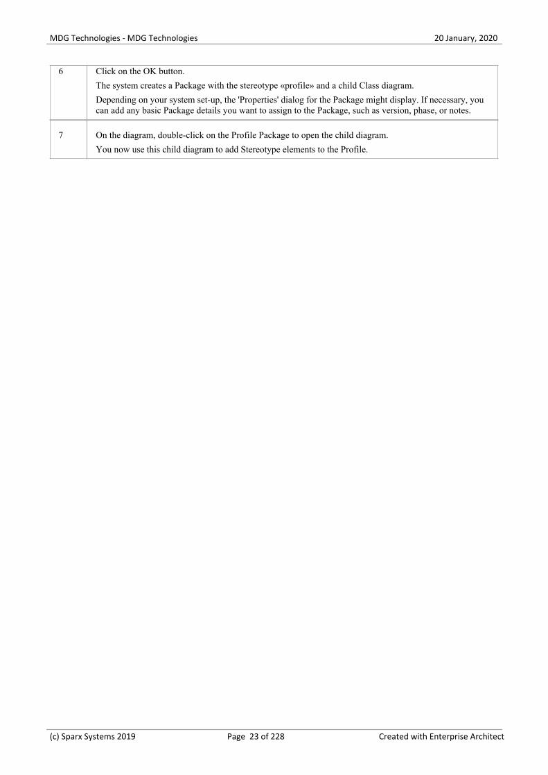
Metaclass element Attributes
Attribute Meaning
_AttInh If set to 1, sets the 'Inherited Features: Show Attributes' checkbox to selected oneach new stereotyped model element.
_AttPkg If set to 1, sets the 'Attribute Visibility: Package' checkbox to selected on each newstereotyped model element.
_AttPri If set to 1, sets the 'Attribute Visibility: Private' checkbox to selected on each newstereotyped model element.
_AttPro If set to 1, sets the 'Attribute Visibility: Protected' checkbox to selected on each newstereotyped model element.
_AttPub If set to 1, sets the 'Attribute Visibility: Public' checkbox to selected on each newstereotyped model element.
compositionKind When applied to an Association, defines whether the source or target end is anaggregate or composite. Permitted values are:
None·
Aggregate at Source·
(c) Sparx Systems 2019 Page 44 of 228 Created with Enterprise Architect
MDG Technologies - MDG Technologies 20 January, 2020
Aggregate at Target·
Composite at Source·
Composite at Target·
_ConInh If set to 1, sets the 'Show Element Compartments: Inherited Constraints' checkboxto selected on each new stereotyped model element.
_Constraint If set to 1, sets the 'Show Element Compartments: Constraints' checkbox to selectedon each new stereotyped model element.
_defaultDiagramType Defines the type of child diagram created when an element is made composite.
direction Automatically created when any type of connector Metaclass element is draggedfrom the 'Profile' toolbox page onto a diagram. You can set a value for this attributein preference to using the _SourceNavigability or _TargetNavigability attributes.
_HideMetaclassIcon Set to True if you are extending an element that will be shown in RectangleNotation and you do not want it to display the 'Metaclass' icon in the top-rightcorner. Affects elements such as Requirements, Components and UseCases.
_HideStype Set the 'Initial Value' field to a comma-separated list of stereotypes to hide thosestereotypes by setting the 'Hide Stereotyped Features' filter for each newstereotyped model element.
_HideUmlLinks Set to True if you are using a metamodel to create your Quick Linker definitionsand you want to exclude UML Quick Linker definitions from your stereotypedsource element's Quick Linker. (The UML Quick Linker definitions wouldotherwise be inherited from the base UML Metaclass.)
_isVertical Set to True for a stereotyped ActivityPartition to make the default Activity Partitionorientation vertical.
_lineStyle Sets the line style of a stereotyped connector; the 'Initial Value' of the attribute canbe one of:
direct·
auto·
custom·
bezier·
treeH (horizontal)·
treeV (vertical)·
treeLH (lateral horizontal)·
treeLV (lateral vertical)·
orthogonalS (orthogonal, square corners)·
orthogonalR (orthogonal, rounded corners)·
_makeComposite Makes each stereotyped element a composite element when it is created.
_MeaningBackwards A natural language meaning for a relationship when read from target to source. Forexample, a <<Flow>> relationship might have _MeaningBackwards set to 'Flowsfrom'. Used in the Traceability window and elsewhere.
_MeaningForwards A natural language meaning for a relationship when read from source to target. For
(c) Sparx Systems 2019 Page 45 of 228 Created with Enterprise Architect

MDG Technologies - MDG Technologies 20 January, 2020
example, a <<Flow>> relationship might have _MeaningForwards set to 'Flows to'.Used in the Traceability window and elsewhere.
_OpInh If set to 1, sets the 'Inherited Features: Show Operations' checkbox to selected oneach new stereotyped model element.
_OpPkg If set to 1, sets the 'Operation Visibility: Package' checkbox to selected on each newstereotyped model element.
_OpPri If set to 1, sets the 'Operation Visibility: Private' checkbox to selected on each newstereotyped model element.
_OpPro If set to 1, sets the 'Operation Visibility: Protected' checkbox to selected on eachnew stereotyped model element.
_OpPub If set to 1, sets the 'Operation Visibility: Public' checkbox to selected on each newstereotyped model element.
_PType If set to 1, sets the 'Show element type (Port or Part only)' checkbox to selected oneach new stereotyped model element.
_ResInh If set to 1, sets the 'Show Element Compartments: Inherited Responsibilities'checkbox to selected on each new stereotyped model element.
_Responsibility If set to 1, sets the 'Show Element Compartments: Requirements' checkbox toselected on each new stereotyped model element.
_Runstate If set to any non-blank value, sets the 'Hide Object Runstate in current diagram'checkbox to selected on each new stereotyped model element.
To show the runstate, omit this attribute or give it a blank value.
_SourceAggregation Deprecated. See compositionKind.
_SourceMultiplicity Sets the multiplicity of the source element, such as 1..* or 0..1.
_SourceNavigability If the connector is non-navigable, set this attribute to 'Non-Navigable'.
If other values are more appropriate, use the direction attribute.
_subtypeProperty Specifies the fully qualified name of the Tagged Value that is used to generate apopup submenu each time an element with the stereotype is created from theToolbox.
The Tagged Value is an enumeration and the submenu consists of a command foreach enumeration literal. The Tagged Value is initialized with whichever commandis selected on the submenu; if none is selected (such as if the user clicks off thesubmenu) then the default value is used as normal.
For example, if you create a BPMN 2 Activity element, a submenu displays listingthe task types such as 'BusinessRule', 'Manual' and 'Receive'. Selecting one of thesevalues sets it as the value of the taskType Tagged Value.
The Tagged Value is effectively the Activity's subtype; in the BPMN 2 profile, inthe format profile::stereotype::tag, the subtypeProperty for the Activity stereotypewould be:
BPMN2.0::Activity::taskType.
(c) Sparx Systems 2019 Page 46 of 228 Created with Enterprise Architect

MDG Technologies - MDG Technologies 20 January, 2020
_Tag If set to 1, sets the 'Show Element Compartments: Tags' checkbox to selected oneach new stereotyped model element.
_tagGroupings Maps the Tagged Values into the tag groups displayed in the 'Tags' tab of theProperties window, in the form:
tagName1=groupName1;tagName2=groupName2;
This facility currently is available for object types only, not for other types such asattributes.
_tagGroups Defines a comma-separated list of required groups in the order in which they are tobe displayed in the 'Tags' tab of the Properties window. For example:
groupName1,groupName2,groupName3
This facility currently is available for object types only, not for other types such asattributes.
_tagGroupStates Maps _tagGroups displayed in the 'Tags' tab of the Properties window to the stateof open or closed, in the form:
groupName1=open;groupName2=closed;
This facility currently is available for object types only, not for other types such asattributes.
_TagInh If set to 1, sets the 'Show Element Compartments: Inherited Tags' checkbox toselected on each new stereotyped model element.
_TargetAggregation Deprecated. See compositionKind.
_TargetMultiplicity Sets the multiplicity of the target element, such as 1..* or 0..1.
_TargetNavigability If the connector is non-navigable, set this attribute to Non-Navigable.
If other values are more appropriate, use the direction attribute.
_UCRect (Only applicable to element types that have a distinct rectangle notation, or toelements that have Shape Scripts that evaluate the 'rectanglenotation' property,which can include element types that do not normally have rectangle notation.)
If set to 1, initially displays the element in rectangle notation. If set to 0, initiallydisplays the element in standard notation.
Notes
Where an attribute is set to 1 to turn a feature on, setting it to 0 turns the feature off·
(c) Sparx Systems 2019 Page 47 of 228 Created with Enterprise Architect

MDG Technologies - MDG Technologies 20 January, 2020
Define a Stereotype as a Metatype
If you want to hide the identity of a custom element as a stereotyped UML element, you can set the _metatype specialattribute in the Stereotype element that defines it. The _metatype attribute also makes custom element types appear incontexts where only Enterprise Architect's inbuilt types would normally appear; for example, in the lists of element typesin the Relationship Matrix.
In this example from SysML, Block is defined as a Stereotype element that extends a UML Class.
However, a SysML user is not interested in UML Classes, only in SysML Blocks. If you set the _metatype attribute toBlock, any element created from that stereotype, while behaving in the same way as a stereotyped Class in most contexts,will:
Show Block <name> rather than Class <name> as the title of its 'Properties' dialog·
Be auto-numbered as Block1 not Class1 on creation, and·
Appear as Block not Class in many other contexts throughout Enterprise Architect·
(c) Sparx Systems 2019 Page 48 of 228 Created with Enterprise Architect

MDG Technologies - MDG Technologies 20 January, 2020
Define Multiple-Stereotype Level
An element can have more than one stereotype applied to it. You can define the level to which multiple stereotypes canbe applied, by creating the _strictness special attribute in the defining Stereotype element. The type of the attribute isStereotypeStrictnessKind, with one of four values in the 'Initial Value' field:
profile, which states that an element of this type cannot be given more than one stereotype from the same Profile·
technology, which states that an element of this type cannot be given more than one stereotype from the same·technology
all, which states that an element of this type cannot have multiple stereotypes at all, or·
none, which is the default behavior and states that there are no restrictions on the use of multiple stereotypes·
This example is from SysML and shows that a «flowPort» cannot have any other stereotype applied to it.
(c) Sparx Systems 2019 Page 49 of 228 Created with Enterprise Architect

MDG Technologies - MDG Technologies 20 January, 2020
Define Creation of Instance
A stereotyped element can be the classifier of instances created from it. You can define how an instance is created fromthat stereotyped element, by adding special attributes to the defining Stereotype. The attributes modify the text on the'Paste As' dialog that displays when a stereotyped element is dragged out of the Browser window onto a diagram.
Attributes
This example from SysML shows the definition of any instances of a SysML Block element that might be created.
When a user drags a SysML Block element from the Browser window onto a diagram, the system checks the_instanceType attribute value and searches the SysML Profile for an element template with a matching _metatypeattribute value, and generates the instance from that. With the example definition you would get a Block element with the«property» stereotype.
Attribute Meaning
_instanceMode Changes the second option for the 'Paste as' field on the dialog to either:
Instance (<element type>) or·
Property (Object)·
The text is determined by the value ('Instance' or 'Property') of the attribute's 'InitialValue' field.
If the attribute is not applied, the option defaults to 'Instance'.
_instanceOwner DEPRECATED
Modifies the second option of the 'Paste as' field on the dialog to:
as Instance of <element type>·
The text is determined by the value of the attribute's 'Initial Value' field, such as'Block'.
If the attribute is not applied, the option defaults to 'Element'.
_instanceType Modifies the second option of the 'Paste as' field on the dialog to:
as Instance of Element (ProfileName::<<stereotype>>)·
The <<stereotype>> value is defined in the 'Initial Value' field of the attribute, andcorresponds to the metatype given to the stereotyped element using the '_metatype'attribute.
(c) Sparx Systems 2019 Page 50 of 228 Created with Enterprise Architect

MDG Technologies - MDG Technologies 20 January, 2020
Define Composite Elements
A stereotyped element can be created automatically as a composite element. You can define this, and whether the childdiagrams of the composite are of a specific type, using special attributes.
To define whether an element is always made composite on creation, you apply the _makeComposite special attribute tothe appropriate metaclass element (not to a stereotype element). A stereotyped class, when created, does not default tohaving a child diagram, so you use the _makeComposite attribute to trigger creation of the child diagram. For astereotyped composite, the child diagram is of the usual default diagram type for the metaclass; you can change the childdiagram type using the _defaultDiagramType special attribute to identify the preferred diagram type,
This example from BPMN shows that a BusinessProcess element is always created as a Composite element with aBPMN custom child diagram.
(c) Sparx Systems 2019 Page 51 of 228 Created with Enterprise Architect

MDG Technologies - MDG Technologies 20 January, 2020
Define Child Diagram Type
If you define a stereotyped element type as being a composite, its child diagram type is initially the same as the defaultfor the Metaclass element you extend. You can change the diagram type to any other of the inbuilt UML or Extendedtypes, or to any of your own Custom diagram types, using the _defaultDiagramType special attribute. As the diagramtype defaults from the Metaclass element, you set the attribute on that Metaclass element (and not the Stereotypeelement) to change the default.
You identify the child diagram type in the 'Initial Value' field for the attribute. The actual values for the inbuilt UML andExtended diagram types are listed in the Initial Values section. If you want to set a Custom diagram type, you prefix thediagram type name with the diagram profile name and '::'. The diagram profile name is the name given to the profilewhen you save it, which by default is the name of the Profile Package or Profile diagram. We recommend that thediagram profile name is based on the technology name. You can also use the _defaultDiagramType attribute forPackages, extending the Package Metaclass element.
These examples show a «BusinessProcess» Activity that, when made a composite element, automatically creates anAnalysis diagram, and a «block» stereotype that creates a SysML InternalBlock Custom diagram.
Initial Values
These strings can be used in the 'Initial Value' field for _defaultDiagramType, to identify the inbuilt UML and Extendeddiagram types:
UML Behavioral::Use Case·
UML Behavioral::Activity·
UML Behavioral::StateMachine·
UML Behavioral::Communication·
UML Behavioral::Sequence·
UML Behavioral::Timing·
UML Behavioral::Interaction Overview·
UML Structural::Package·
UML Structural::Class·
UML Structural::Object·
UML Structural::Composite Structure·
UML Structural::Component·
UML Structural::Deployment·
Extended::Custom·
Extended::Requirements·
(c) Sparx Systems 2019 Page 52 of 228 Created with Enterprise Architect

MDG Technologies - MDG Technologies 20 January, 2020
Extended::Maintenance·
Extended::Analysis·
Extended::User Interface·
Extended::Data Modeling·
Extended::ModelDocument.·
Notes
Although we recommend that the diagram profile name for Custom diagram types is based on the technology name,·the attribute prefix is not a direct reference to the technology name
(c) Sparx Systems 2019 Page 53 of 228 Created with Enterprise Architect

MDG Technologies - MDG Technologies 20 January, 2020
Define Tag Groupings
In developing a stereotyped element in a Profile, you might define a large number of Tagged Values. For example, aBPMN Activity element in the BPMN 2.0 Profile has 30 Tagged Values. By default, in the 'Tags' tab of the Propertieswindow for the element, these Tagged Values would initially all be displayed in alphabetical order, which might splitrelated tags if they happen to have alphabetically distant names. To keep related tags together and control which tags areinitially shown, in the BPMN 2.0 Profile the Tagged Values have been grouped. You can apply the same solution, usingthree tag grouping special attributes in the Metaclass element extended by the Stereotype element in which the tags aredefined as attributes.
You apply the grouping using:
_tagGroups to define the group names·
_tagGroupings to define which tags go into each group·
_tagGroupStates to define which tag groups are initially expanded in the 'Tags' tab of the Properties window, and·which are collapsed
The 'Tags' tab of the Properties window for the BPMN 2.0 Activity element initially displays as shown:
Activity Metaclass Attributes
To achieve that display of the BPMN 2.0 Activity Tagged Values, the Technology Developer defined the specialattributes in the Activity Metaclass element as shown:
Attribute Values
_tagGroups Base Element,Activity,Task,AdHoc,Loop,Sub-Process,CallableElement,Execution,Other
_tagGroupings auditing=Base Element;categoryValue=Base Element;documentation=BaseElement;monitoring=Base
(c) Sparx Systems 2019 Page 54 of 228 Created with Enterprise Architect

MDG Technologies - MDG Technologies 20 January, 2020
Element;activityType=Activity;calledActivityRef=Activity;instantiate=Activity;isACalledActivity=Activity;isATransaction=Activity;isForCompensation=Activity;resources=Activity;messageRef=Task;operationRef=Task;rendering=Task;script=Task;scriptFormat=Task;taskType=Task;adHoc=AdHoc;adHocOrdering=AdHoc; ...(and so on)
_tagGroupStates BaseElement=closed;Activity=open;Task=open;AdHoc=closed;Loop=closed;Sub-Process=closed;Callable Element=closed;Execution=closed;Other=closed
Example
Shown here, is an simple example of how to use the tag grouping attributes.
Notes
This facility currently is available for object types only, not for other types such as attributes·
(c) Sparx Systems 2019 Page 55 of 228 Created with Enterprise Architect

MDG Technologies - MDG Technologies 20 January, 2020
Introducing the Metamodel Views
Enterprise Architect includes an extremely powerful and flexible system of Views of both system-defined anduser-defined metamodels. The Views system provides highly focused diagrams that limit the number of elements andconnections available to only the core required to achieve a specific task. For example, a Hierarchy View imposed on aClass diagram might limit the only element available to 'Class' and the only connector to 'Inheritance'.
Using the Views system to guide the modeling palette and relationships available, you will build tight and purposefuldiagrams that use only the required elements within the current modeling context. Cutting out the noise and reducing theset of constructs available is a great way of making sure a design is addressing the intended purpose and avoidingextraneous elements that might negatively impact the readability and correctness of the model.
Metamodel Views
Category Description
System Enterprise Architect provides a wide range of built-in Metamodel Views thataddress numerous modeling scenarios and domains. Many of the Model Wizardpatterns are pre-set with a Metamodel View, and the 'New Diagram' dialog includesmany derivative diagram views that extend and refine the capabilities of the basediagram types.
Custom In addition to using the system-defined Metamodel based views in EnterpriseArchitect, it is also possible to create your own Metamodels and easily add them tothe current model, where you and other modelers can then apply them to variousdiagrams as needed. For example, you might define a specific Metamodel set thataddresses the needs of Requirements modeling in your organization, and thenmandate that all Requirement diagrams use that Metamodel View.
View System Facilities
Facility Description
Diagram Filter In addition to limiting the available palette, the View system also allows themodeler to enable a diagram filter that will gray out any elements that are not partof the current view set. This allows the modeler to correct any parts of their modelthat don't meet the purpose of the selected View, or to filter out elements that arerequired to be there, but do not form part of the current modeling goal.
Diagram Properties The 'Properties' dialog for a diagram includes a drop-down list of available Viewsfor the currently selected diagram type. Selecting one of these Views will reducethe palette of constructs available and limit the entries in the Quicklinker. Modelerscan easily activate a View or even remove one if necessary - the actual modelcontent will not change.
Diagram Views The 'New Diagram' dialog includes a number of different Views that offer differentpalette sets and focus goals for diagram types such as UML, SysML, BPMN andUAF, amongst others. If you have the goal of modeling a simple Activity diagramwith no advanced features, the Simple Activity View under the UML Activitydiagram section could be a better option than using the full Activity diagram set.
(c) Sparx Systems 2019 Page 56 of 228 Created with Enterprise Architect

MDG Technologies - MDG Technologies 20 January, 2020
(c) Sparx Systems 2019 Page 57 of 228 Created with Enterprise Architect

MDG Technologies - MDG Technologies 20 January, 2020
Built-in Metamodel Diagram View
The 'New Diagram' dialog includes a number of different Views that offer different palette sets and focus goals fordiagram types such as UML, SysML, BPMN and UAF, amongst others. As an example, if you have the goal of modelinga simple SysML Block Definition diagram with no advanced features, the 'Basic Blocks View' under the 'SysML 1.5Block Definition Diagram' section might be a better option than using the full Block Definition diagram set. Thisexample is used to provide values in the procedures in this topic.
Working with Diagram Views
Step Action
1 In the Browser window, click on the Package or element under which to place the diagram.
Open the 'New Diagram' dialog, select 'SysML 1.4 Views:: Basic Blocks' and click on the OK button tocreate the diagram.
2 In the Properties window for the created diagram, the 'Applied Metamodel' field will show the applieddiagram View. You can also click on the drop-down arrow in this field and select another of the availablediagram Views from the list.
(c) Sparx Systems 2019 Page 58 of 228 Created with Enterprise Architect

MDG Technologies - MDG Technologies 20 January, 2020
3 In the Diagram Toolbox, the restricted set of elements and relationships associated with the diagram viewwill be visible.
(c) Sparx Systems 2019 Page 59 of 228 Created with Enterprise Architect

MDG Technologies - MDG Technologies 20 January, 2020
Changing the diagram views in the 'Applied Metamodel' option list will change the elements andrelationships in the Toolbox.
4 Selecting the 'Filter to Metamodel' option in the Properties window will gray out any elements that are notpart of the current diagram View set. This allows you to correct any parts of your model that don't meetthe purpose of the selected View, or to filter out elements that might be required to be there, but do notform part of the current modeling goal.
(c) Sparx Systems 2019 Page 60 of 228 Created with Enterprise Architect

MDG Technologies - MDG Technologies 20 January, 2020
(c) Sparx Systems 2019 Page 61 of 228 Created with Enterprise Architect

MDG Technologies - MDG Technologies 20 January, 2020
Custom Metamodel Diagram View
Enterprise Architect has a wide range of built-in diagram views, but you can also create your own Metamodels thatdefine custom diagram Views. For example, you might define a specific Metamodel that addresses the needs ofRequirements modeling in your organization, and then mandate that all Requirements diagrams use that diagram Viewinstead of the built-in Requirement diagram Views. You can quickly add your diagram Views to the current model,where you or other modelers can apply them to your diagrams.
As an illustration, suppose you decide to make available a new SysML 1.4 Block Definition diagram View in yourproject, called 'MyView'. Users will access it through the 'New Diagram' dialog, expanding the Block Definition diagramtype.
The fully extended name of the diagram View reflects the parent Profile name (MyProfile) and the View name(MyView) - hence 'MyProfile::MyView'. You could call the example View SysML 1.4 Views:: MyView to indicate thatit is a member of the SysML 1.4 View suite.
If you are extending a UML base diagram type, with the Profile name 'UML', the equivalent View name could besomething such as 'UML::Full Class'.
The users select the example diagram View to create a very simple SysML 1.4 Block diagram that can have:
Two types of element:· - a SysML 1.4 Block element (an extended Class from the SysML 1.4 technology) - a MyStereo element that you are defining within your new metamodel 'MyView' as a Class with the stereotype MyStereo
One type of connector - a standard SysML Block Generalization (which is the same as a standard UML·Generalization)
(c) Sparx Systems 2019 Page 62 of 228 Created with Enterprise Architect

MDG Technologies - MDG Technologies 20 January, 2020
The diagram View makes the elements and connector available from the Toolbox, as shown, and from the Quicklinker.
The table Create Custom Diagram View in a Profile explains how to create a Metamodel that defines a new diagramView, finishing with the MyView example.
Access
Ribbon Design > Diagram > Toolbox: > Profile > Metamodel
Keyboard Shortcuts Ctrl+Shift+3 : > Profile > Metamodel
Create Custom Diagram View in a Profile
Operation Action
Create the Profile diagram In your profile Package, create a new Package diagram and, in the DiagramToolbox, open the 'Profile' page (select the 'Design > Diagram > Toolbox' ribbon
option, then click on and select 'Profile').
Drag the 'Profile' icon onto the diagram and give it the name 'MyProfile', selectingto add a child Class diagram of the name 'MyView', which you open.
Expand the 'Metamodel' page in the Toolbox and note the:
'View Specification' element, which you can use to create a custom diagram·View
'Exposes' connector, which you use to specify the contents of the Toolbox page·associated with the custom diagram View
Add View Specification Within a Profile, you use the 'View Specification' stereotyped element to identifythe new custom diagram View as an extension of an existing built-in or stereotyped
(c) Sparx Systems 2019 Page 63 of 228 Created with Enterprise Architect

MDG Technologies - MDG Technologies 20 January, 2020
diagram.
Drag the 'View Specification' icon onto the Profile diagram, and give the element aname; in our example, 'MyView'.
The first thing to consider when defining a new View, is what diagram type ortypes it should be available for. The next two rows show how to define a View for aUML diagram and a Profile diagram.
In both cases, click on the 'Extension' icon and drag from the View Specification tothe diagram-type element, to create the Extension connector.
Extending a UML DiagramType
To extend a base UML diagram type, drag the 'Class' icon from the Toolbox ontothe diagram and, on the Properties window, give the element:
The exact name of the diagram type (as listed in the Built-in Diagram Types·Help topic) such as 'Logical' (for a Class diagram), and
The stereotype <<metaclass>>·
This example shows 'MyView' as previously created, extending the UMLComponent diagram.
«view specification»MyView
«metaclass»Component
The result is that in the 'New Diagram' dialog, an extra View is added under theUML Component Diagram type.
Extending a ProfiledDiagram Type
To extend a profiled diagram type, such as a BPMN or SysML diagram type, dragthe 'Stereotype' icon onto the diagram and give the Stereotype element the exactfully qualified name of the diagram type.
Because this is a reference to an external stereotype, it should also be marked asAbstract to prevent it being exported into the profile. To do that, display theProperties window, expand the 'Advanced' section and select the 'Abstract'checkbox.
This example shows 'MyView' as previously created, extending the GRA-UMLComponent Diagram type.
«view specification»MyView
GRA-UML::GRA
Component{abstract}
The result is that the 'New Diagram' dialog will show the View we are definingunder the GRA-UML component diagram.
Note: If you do not know the fully qualified name of the diagram type you areextending, query the API to get the 'Metatype' field. In a Javascript console you canuse:
?GetCurrentDiagram().MetaType
Exposing Objects in theDiagram View Toolbox
An Exposes connector adds an object to the Toolbox page for the diagram View.For each element and connector to add to the diagram View's Toolbox page, youdrag a 'definition element' onto the diagram and then click on the 'Exposes' icon inthe Toolbox 'Profile' page and drag the cursor from the View Specification elementto the 'definition element' to create the connector.
The type of definition element depends on whether you are exposing a base UMLelement or a stereotyped element, as shown in the next two rows.
(c) Sparx Systems 2019 Page 64 of 228 Created with Enterprise Architect

MDG Technologies - MDG Technologies 20 January, 2020
Exposing UML ElementTypes
If you are using base UML element or connectors in your custom diagram View,then for each element or connector:
Drag the 'Metaclass' icon from the Toolbox 'Profile' page onto the diagram and1.give it the name of the base element or connector type it represents and
Add the Exposes connector between the View Specification element and the2.Metaclass element
For example:
Exposing Profiled ElementTypes
If you are defining a new stereotyped object in the diagram view, or usingstereotyped elements already defined in other profiles, then for each element orconnector:
Drag the 'Stereotype' icon from the Toolbox 'Profile' page onto the diagram,1.and give the element the name of the stereotyped element or connector itrepresents
If the Stereotype is defined in another profile, expand the 'Advanced' section of2.the Properties window and select the 'Abstract' checkbox
If the Stereotype is being defined here, add to the diagram the base element3.that the Stereotype extends, and create an Extension connector between theStereotype and base element
Add the Exposes connector between the View Specification element and the4.Stereotype element
For example:
(c) Sparx Systems 2019 Page 65 of 228 Created with Enterprise Architect

MDG Technologies - MDG Technologies 20 January, 2020
Completing the Example With reference to the earlier rows in the table, on the MyView Class diagram (thechild of the MyProfile diagram):
Create the View Specification element MyView.1.
Create the Stereotype element SysML1.4::Block Definition and set it to2.Abstract.
Connect the View Specification to the SysML1.4::Block Definition with an3.Extension connector.
Create a Metaclass element called Generalization.4.
Create a Stereotype element called SysML1.4::Block and set it to Abstract.5.
Create a Stereotype element called MyStereo and a Metaclass element called6.UML Class and connect the Stereotype to the Metaclass with an Extensionconnector.
Connect the View Specification element to the Generalization element, the7.SysML1.4::Block element and the MyStereo element, each with an Exposesconnector.
This illustration represents the diagram that you have created:
(c) Sparx Systems 2019 Page 66 of 228 Created with Enterprise Architect

MDG Technologies - MDG Technologies 20 January, 2020
As you complete your diagram view, you might decide that elements of one typeshould be connected to elements of the same type or of other types by using specifickinds of connector. You would define this using Meta-Relationship connectors, asdiscussed in the Define Metamodel Constraints Help topic.
Save the View Specification diagram. You can now can add it to an MDGTechnology file as part of its parent Profile; you add the parent Profile to the 'MDGTechnology Wizard - Profile files selection' page. See the Add a Profile Help topic.
(c) Sparx Systems 2019 Page 67 of 228 Created with Enterprise Architect

MDG Technologies - MDG Technologies 20 January, 2020
Define Metamodel Constraints
When extending UML to develop a domain-specific Profile, Enterprise Architect allows you to specify constraints torestrict the connectors that can be drawn from a Stereotype, either using the Quick Linker or from the Toolbox. Theseconstraints are defined using the relationships under the 'Metamodel' page of the 'Profile' toolbox.
Access
Ribbon Design > Diagram > Toolbox: > Profile
Keyboard Shortcuts Ctrl+Shift+3
Add Metamodel Constraints to a Profile
Item Detail
Meta-Relationship
A «metarelationship» connector between two Stereotypes is used to specify a valid UML Connectorbetween these two Stereotypes.
The name of the UML Connector should be set in the tag 'metaclass' on the «metarelationship» connector.
(c) Sparx Systems 2019 Page 68 of 228 Created with Enterprise Architect

MDG Technologies - MDG Technologies 20 January, 2020
In the Profile example, a «metarelationship» connector is drawn from ServiceSpecification toServiceInterface and the name of the UML Connector is specified in the 'Tags' tab of the Propertieswindow for the connector.
After importing this Profile into a model, Enterprise Architect will show the UML Connector when theQuick Linker is used to draw a relationship between a ServiceSpecification and ServiceInterface.
Meta-Constraint
A «metaconstraint» connector between two Stereotypes is used to specify a constraint between these twoStereotypes.
The constraint should be set in the tag 'umlRole' on the Meta-Constraint connector.
(c) Sparx Systems 2019 Page 69 of 228 Created with Enterprise Architect

MDG Technologies - MDG Technologies 20 January, 2020
In the Profile example, a «metaconstraint» connector is drawn from ActualProjectMilestone toProjectMilestone and the constraint is specified as classifier on the tag 'umlRole' in the connector's TaggedValues.
After importing this Profile into a model, Enterprise Architect will show only the ProjectMilestonestereotyped elements when assigning a classifier for ActualProjectMilestone element.
Constraint values for the tag 'umlRole' include:
classifier – restricts the classifier for the source Stereotype element to the target Stereotype element·
type – restricts the type for the source Stereotype element to the target Stereotype element·
behavior - restricts the behavior for the source Stereotype element to the target Stereotype element·
conveyed - restricts the conveyed element for the source Stereotype element to the target Stereotype·element
slot - restricts the slot for the source Stereotype element to the target Stereotype element·
client/source/end[0].role/informationSource – restricts the source of a connector to the target·Stereotype element
supplier/target/end[1].role/informationTarget - restricts the target of a connector to the target·Stereotype element
realizingConnector/realizingActivityEdge/realizingMessage - restricts the relationship that can realize·an information flow
typedElement/instanceSpecification – when dropping as classifier from the Browser window, this·constraint restricts the type to the target Stereotype element
owner/class/activity/owningInstance – restricts the container of this element to the target Stereotype·element; this constraint is used to create embedded element rules for the Quick Linker and validatenesting during Model Validation
ownedElement/ownedAttribute/ownedOperation/ownedParameter/ownedPort – restricts the·element/attribute/operation/parameter/port that can be owned by the source Stereotype element; thisconstraint is typically used to validate nesting during Model Validation
annotatedElement/constrainedElement – restricts the target of a Note Link connector to the target·Stereotype element
StereotypedRelat
A «stereotypedrelationship» connector between two Stereotypes is used to specify a valid stereotypedconnector between these two Stereotypes.
The stereotype name should be set in the tag 'stereotype' on the «stereotypedrelationship» connector.
(c) Sparx Systems 2019 Page 70 of 228 Created with Enterprise Architect
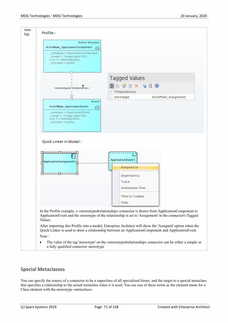
MDG Technologies - MDG Technologies 20 January, 2020
ionship
In the Profile example, a «stereotypedrelationship» connector is drawn from ApplicationComponent toApplicationEvent and the stereotype of the relationship is set to 'Assignment' in the connector's TaggedValues.
After importing this Profile into a model, Enterprise Architect will show the 'Assigned' option when theQuick Linker is used to draw a relationship between an ApplicationComponent and ApplicationEvent.
Note :
The value of the tag 'stereotype' on the «stereotypedrelationship» connector can be either a simple or·a fully qualified connector stereotype
Special Metaclasses
You can specify the source of a connector to be a superclass of all specialized forms, and the target to a special metaclassthat specifies a relationship to the actual metaclass when it is used. You use one of these terms as the element name for aClass element with the stereotype «metaclass».
(c) Sparx Systems 2019 Page 71 of 228 Created with Enterprise Architect

MDG Technologies - MDG Technologies 20 January, 2020
Item Detail
source.metatype
The target element must match the exact stereotype defined at the source.
source.metatype.general
The target element can match the exact stereotype used at the source, and any concrete (isAbstract=false)generalized stereotypes.
source.metatype.specific
The target element can match the exact stereotype used at the source, and any concrete (isAbstract=false)specialized stereotypes.
source.metatype.both
The target element can match the exact stereotype used at the source, and any concrete (isAbstract=false)generalized or specialized stereotypes.
<none>
Use this metaclass name when you want to prevent the source element from inheriting the specifiedconnector from its supertypes.
(c) Sparx Systems 2019 Page 72 of 228 Created with Enterprise Architect

MDG Technologies - MDG Technologies 20 January, 2020
Constraints on Meta-Constraint connector
When creating a domain-specific Profile, Enterprise Architect allows you to specify constraints between relatedStereotypes. As an example, you can restrict the element that can be set as a classifier on a Stereotyped element.
A Meta-Constraint connector, on the 'Metamodel' page of the 'Profile' toolbox, between two Stereotypes is used tospecify the constraint between the two Stereotypes. The constraint should be set in the tag 'umlRole' on theMeta-Constraint connector.
Access
Ribbon Design > Diagram > Toolbox : > Profile > Metamodel
Keyboard Shortcuts Ctrl+Shift+3 : > Profile > Metamodel
Constraint values for tag 'umlRole'
Constraint values for the tag 'umlRole' on the Meta-Constraint connector are:
Constraint
Description
classifier
Set this constraint to restrict the classifier for the source Stereotype element as the target Stereotypeelement.
In the Profile example, a Meta-Constraint connector is drawn from the stereotype ActualCondition toCondition and the constraint is specified as 'classifier' on the tag 'umlRole' in the connector's list ofTagged Values. This means that only a 'Condition' stereotyped element can be set as the classifier for anActualCondition stereotyped element.
After importing this Profile into a model, Enterprise Architect will show only Condition stereotyped
(c) Sparx Systems 2019 Page 73 of 228 Created with Enterprise Architect

MDG Technologies - MDG Technologies 20 January, 2020
elements in the 'Select DataType' dialog when setting the DataType for an ActualCondition stereotypedelement.
type Set this constraint to specify the type for the target Stereotype element when it is dropped from theBrowser window into a diagram while pressing and holding the Ctrl key.
In the Profile example, a Meta-Constraint connector is drawn from the stereotype CapabilityProperty toCapability and the constraint is specified as 'type' on the tag 'umlRole' in the 'Tags' tab of the connector'sProperties window.
After importing this Profile into a model, when a Capability stereotyped element is dropped from theBrowser window into a diagram while pressing and holding the Ctrl key, the 'Paste <item>' dialog willdisplay CapabilityProperty as one of the options in the 'Drop as' list.
behavior
Set this constraint to restrict the behavior for the source Stereotype element to the same as the targetStereotype element.
In the Profile example, a Meta-Constraint connector is drawn from stereotype FunctionAction to Functionand the constraint is specified as 'behavior' on the tag 'umlRole' in the 'Tags' tab of the Properties windowfor the connector. This means that only a 'Function' stereotyped element can be set as classifier for aFunctionAction stereotyped element.
(c) Sparx Systems 2019 Page 74 of 228 Created with Enterprise Architect

MDG Technologies - MDG Technologies 20 January, 2020
After importing this Profile into a model, Enterprise Architect will show only Function stereotypedelements in the 'Select Activity' dialog when setting the behavior for a FunctionAction stereotypedelement.
conveyed
Set this constraint to restrict the Information Items that can be conveyed on a Stereotype that extends theInformation Flow connector.
In the Profile example, a Meta-Constraint connector is drawn from stereotype OperationalExchange toOperationalExchangeItem and the constraint is specified as 'conveyed' on the tag 'umlRole' in the 'Tags'tab of the Properties window for the connector. This means that when an OperationalExchange connectoris drawn, the Information Items that can be conveyed on the connector are restricted toOperationalExchangeItem stereotyped elements.
slot Set this constraint to restrict the slot for the Stereotype element as the target Stereotype element.
In the Profile example, a Meta-Constraint connector is drawn from the stereotype ActualProject toActualProjectRole and the constraint is specified as 'slot' on the tag 'umlRole' in the connector's TaggedValues. Note that the stereotype 'ActualProject' extends UML Object and can classify stereotype 'Project'.When an instance specification for the Project element is created (by dropping it from the Browserwindow into a diagram while pressing and holding the Ctrl key) in the model:
The created instance specification will be stereotyped ActualProject·
Any Property in the 'Project' stereotyped element will be created as an 'ActualProjectRole'·stereotyped Property in the instance specification
client/
source/
end[0].role/
informationSource
Set this Model Validation constraint to restrict the start element of a Stereotyped connector.
(c) Sparx Systems 2019 Page 75 of 228 Created with Enterprise Architect

MDG Technologies - MDG Technologies 20 January, 2020
In the Profile example, a Meta-Constraint connector is drawn from stereotype 'FunctionControlFlow' to'FunctionAction' and the constraint is specified as 'source' on the tag 'umlRole' in the connector's TaggedValues. This means that when a FunctionControlFlow connector is drawn, the source element should be aFunctionAction stereotyped element. Otherwise, Enterprise Architect will flag an error when performing aModel Validation.
supplier/
target/
end[1].role/
informationTarget
Set this model validation constraint to restrict the target element of a Stereotyped connector.
realizingConnector/
realizingActivityEdge/
realizingMessage
Set this constraint to restrict the relationship that can realize an Information Flow connector.
(c) Sparx Systems 2019 Page 76 of 228 Created with Enterprise Architect
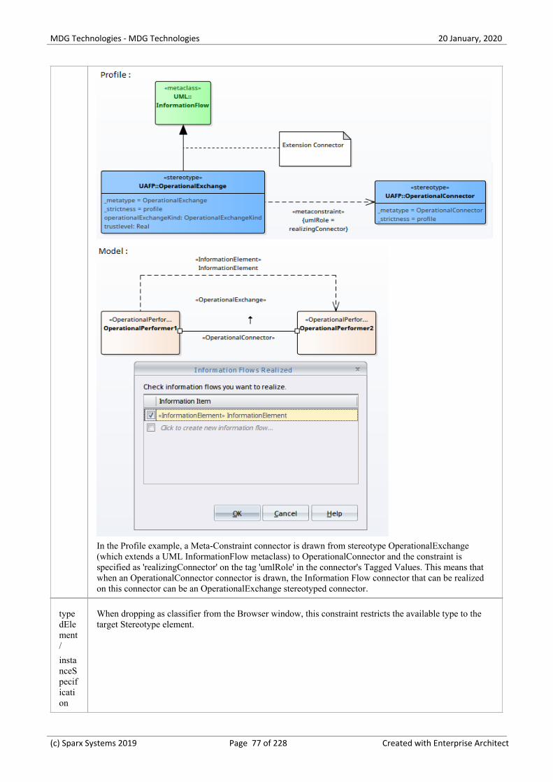
MDG Technologies - MDG Technologies 20 January, 2020
In the Profile example, a Meta-Constraint connector is drawn from stereotype OperationalExchange(which extends a UML InformationFlow metaclass) to OperationalConnector and the constraint isspecified as 'realizingConnector' on the tag 'umlRole' in the connector's Tagged Values. This means thatwhen an OperationalConnector connector is drawn, the Information Flow connector that can be realizedon this connector can be an OperationalExchange stereotyped connector.
typedElement/
instanceSpecification
When dropping as classifier from the Browser window, this constraint restricts the available type to thetarget Stereotype element.
(c) Sparx Systems 2019 Page 77 of 228 Created with Enterprise Architect

MDG Technologies - MDG Technologies 20 January, 2020
owner/
class/
activity/
owningInstance
Set this constraint to restrict the container/owner of the element to the target Stereotype element. Thisconstraint is used to create embedded element rules for the Quick Linker and to validate nesting duringModel Validation.
In the Profile example, a Meta-Constraint connector is drawn from the stereotype DataElement toDataModel and the constraint is specified as 'owner' on the tag 'umlRole' in the connector's TaggedValues. This means that DataElement stereotyped elements can be children of DataModel stereotypedelement. In other words, only DataModel can contain/own DataElements in the Model.
ownedElement/
ownedAttribute/
ownedOperation/
ownedParameter/
ownedPort
Set this constraint to restrict the element/attribute/operation/parameter/port that can be owned by thesource Stereotype element. This constraint is typically used to validate nesting during Model Validation.
In the Profile example, a Meta-Constraint connector is drawn from stereotype ProjectMilestone toProjectTheme and the constraint is specified as 'ownedAttribute' on the tag 'umlRole' in the connector'sTagged Values. This means that ProjectMilestone stereotyped elements can contain 'ProjectTheme'stereotyped attributes in the model.
annotatedElement/
constrainedElement
Set this model validation constraint to restrict the target of a NoteLink connector.
In the Profile example, a Meta-Constraint connector is drawn from stereotype SecurityControlFamily toSecurityControl and the constraint is specified as 'annotatedElement' on the tag 'umlRole' in theconnector's Tagged Values.
(c) Sparx Systems 2019 Page 78 of 228 Created with Enterprise Architect

MDG Technologies - MDG Technologies 20 January, 2020
When the Profile is imported into a model, the target of a NoteLink connector from aSecurityControlFamily stereotyped element should be a SecurityControl stereotyped element. Otherwise,Enterprise Architect will flag an error when performing a Model Validation.
(c) Sparx Systems 2019 Page 79 of 228 Created with Enterprise Architect

MDG Technologies - MDG Technologies 20 January, 2020
Quick Linker
When a user is creating new elements and connectors on a diagram they can simplify the process by using the QuickLinker arrow, which displays a list of the common connectors that can issue from a selected element and a list of thecommon elements each connector can connect to. These lists are derived from a Quick Linker definition, which is aComma Separated Value (CSV) format file.
As part of a Profile, you can add to or replace the built-in Quick Linker definitions using your own definitions. These canbe derived from:
A Quick Linker Definition Format CSV file that you integrate with the Profile by adding the CSV text to a·Document Artifact element on the Profile diagram (preferred method) - see the Quick Linker Definition Format Helptopic
A custom metamodel diagram View, including a set of metamodel constraints that define what types of element are·connected by what type(s) of connector (second preferred method) - see the Introducing the Metamodel Views andDefine Metamodel Constraints Help topics)
A Relationship Table CSV file that you integrate with the Profile also by adding the CSV text to a Document·Artifact element on the Profile diagram (best only for implementing complex relationship rules that don'tnecessarily correspond to a defined metamodel) - see the Relationship Table help topic
Notes
The philosophy behind a Quick Linker definition is not to provide a complete list of valid or legal connections, but a·short and convenient list of the commonest connections for the given context
(c) Sparx Systems 2019 Page 80 of 228 Created with Enterprise Architect

MDG Technologies - MDG Technologies 20 January, 2020
Quick Linker Definition Format
In order to replace or change the Quick Linker menus that are displayed when a user drags the Quick Linker arrow fromone of your profile elements on a diagram, you can create or edit the corresponding Quick Linker definition. This is aComma Separated Value (CSV) text file consisting of records (rows), each record consisting of 23 comma-separatedfields as defined in the table.
Some of these fields define the menu command and some act as filters, with the entry being ignored if the filter conditionisn't met.
A Quick Linker definition can include comments: all lines in which // are the first two characters are ignored byEnterprise Architect. Quotes (" ") in the field values are not required.
Each record of the Quick Linker definition represents a single combination of entries on the Quick Linker menus; that is,for the selected source element, a specific connector type and specific target element type. A menu is populated from allrows that satisfy the filters; that is, the first menu lists all defined connectors that are legal and valid for the sourceelement type, and the second menu lists all target elements that are legal and valid for the combination of source elementand connector type.
Quick Linker Definition fields
Column Title (enter as comment for guidance)
A Source Element Type
Description: Identifies a valid source element in the Profile. To indicate that thesource element can be any specialization of an abstract UML Metaclass, add theprefix '@' to the Metaclass name; for example, '@Classifier', '@NamedElement'.
If a connector is being dragged away from this type of element, the row isevaluated. Otherwise, the row is ignored.
If the source is another connector, prefix the connector type with the word 'link:';for example, 'link:ControlFlow'.
B Source Stereotype Filter
Description: Identifies a stereotype of the source element base type (for example,an Event source element can be a normal Event, or a Start Event, IntermediateEvent or End Event stereotyped element). The stereotype can be a fully qualifiedstereotype or the name of a stereotype within the current profile.
If set, and if a connector is being dragged away from an element of this stereotype,the row is evaluated. Otherwise, the row is ignored.
C Target Element Type
Description: Identifies a valid target element in the Profile. To indicate that thetarget element can be any specialization of an abstract UML Metaclass, add theprefix '@' to the Metaclass name; for example, '@Classifier', '@NamedElement'.
If set, and if a connector is being dragged onto this type of element, the row isevaluated.
If blank, and if a connector is being dragged onto an empty space on the diagram,the row is evaluated.
Otherwise the row is ignored.
If the target is another connector, prefix the connector type with the word 'link:'; forexample, 'link:ControlFlow'.
D Target Stereotype Filter
(c) Sparx Systems 2019 Page 81 of 228 Created with Enterprise Architect

MDG Technologies - MDG Technologies 20 January, 2020
Description: Identifies a stereotype of the target element base type.
If set, if Target Element Type is also set, and if a connector is being dragged ontoan element of this stereotype, the row is evaluated. Otherwise, the row is ignored.
E Diagram Filter
Description: Contains either an inclusive list or an exclusive list of diagram types,which limits the diagrams the specified connector can be created on.
Each diagram name is terminated by a semi-colon; for example:· Collaboration;Object;Custom;
Custom diagram types from MDG Technologies can be referenced using the·fully qualified diagram type (DiagramProfile::DiagramType); for example: BPMN2.0::BusinessProcess;BPMN2.0::Choreography;BPMN2.0::Collaboration;
As a shorthand for all diagram types in a diagram profile you can use the '*'·wildcard, which must be preceded by the diagram profile ID; for example: BPMN2.0::*;
Each excluded diagram name is preceded by an exclamation mark; for·example: !Sequence;
This column overrides the 'Filter to Toolbox' setting for the Quicklinker, which isenabled by default on diagrams. To force a connector to be visible on all diagrams,you can exclude a diagram type that doesn't exist. For example:
!TBFilter
Note: the preferred mechanism for executing a diagram filter is now the toolboxfilter. This automatically shows the relevant connector types based on the currentdiagram, including for diagram types as they are defined in the future by othertechnologies.
F New Element Type
Description: Defines the type of element to be created if the connector is draggedinto open space, provided that the 'Create Element' field is set to True.
This value cannot be a connector type.
G New Element Stereotype
Description: Defines the type of element stereotype to be created if the connector isdragged into open space, provided that the 'Create Element' field is set to True.This can be a fully qualified stereotype, or the name of a stereotype within thecurrent profile.
H New Link Type
Description: Defines the type of connector to create, if 'Create Link' is also set toTrue.
I New Link Stereotype
Description: Defines the stereotype of the connector created, if 'Create Link' is alsoset to True. This field is required when adding Quicklinker records to built-in types.The stereotype can be a fully qualified stereotype, or the name of a stereotypewithin the current profile.
J New Link Direction
Description: Defines the connector direction, which can be:
directed (always creates an Association from source to target)·
(c) Sparx Systems 2019 Page 82 of 228 Created with Enterprise Architect

MDG Technologies - MDG Technologies 20 January, 2020
from (always creates an Association from target to source)·
undirected (always creates an Association with unspecified direction)·
bidirectional (always creates a bi-directional Association), or·
to (creates either a directed or undirected Association, depending on the value·of the 'Association Direction' field)
Not all of these work with all connector types; for example, you cannot create abi-directional Generalization.
K New Link Caption
Description: Defines the text to display in the 'Quick Linker' menu if a newconnector is being created but not a new element.
L New Link & Element Caption
Description: Defines the text to display in the 'Quick Linker' menu if a newconnector AND a new element are being created.
M Create Link
Description: If set to True, results in the creation of a new connector; leave blank tostop the creation of a connector.
N Create Element
Description: If set to True and a connector is being dragged onto an empty space onthe diagram, results in the creation of a new element.
Leave blank to stop the element from being created. This overrides the values of'Target Element Type' and 'Target Stereotype Filter'.
O Disallow Self connector
Description: Set to True if self connectors are invalid for this kind of connector;otherwise leave this field blank.
P Exclusive to ST Filter +
No inherit from Metatype
Description: Set to True to indicate that elements of type 'Source Element Type'with the stereotype 'Source Stereotype Filter' do not display the Quick Linkerdefinitions of the equivalent unstereotyped element.
This field is ignored if the 'Source Stereotype Filter' field (Column B) is empty.
Q Menu Group
Description: Indicates the name of the submenu in which a menu item is created.
This column only applies when creating a new element; that is, the user is draggingfrom an element to an empty space on the diagram, or over a target element tocreate a new embedded element.
R Complexity Level
Description: Contains numerical bitmask values that identify complex functionality.
0 = no complex functionality·
4 = Force blank source stereotype; this row will be skipped unless the source·element has no stereotype
8 = force blank target stereotype; this row will be skipped unless the target·element has no stereotype
(c) Sparx Systems 2019 Page 83 of 228 Created with Enterprise Architect

MDG Technologies - MDG Technologies 20 January, 2020
16 = treat the value in the 'Source Stereotype Filter' column (column B) as a·Source Name Filter instead
32 = treat the value in the 'Target Stereotype Filter' column (column D) as a·Target Name Filter instead, and use the value in the 'New Element Stereotype'column (column G) as the name of the newly created element
64 = treat the value in the 'Source Stereotype Filter' column (column B) as a·Source Classifier Name Filter instead
128 = treat the value in the 'Target Stereotype Filter' column (column D) as a·Target Classifier Name Filter instead, and use the value in the 'New ElementStereotype' column (column G) as the name of the classifier of the newlycreated element, creating an additional new element if an element of that namedoesn't exist in the current model
The values can be added together to combine functionality; for example, 192combines the functionality of 64 and 128.
S Target Must Be Parent
Description: Set to True if the menu item should only appear when dragging from achild element to its parent; for example, from a Port to its containing Class.Otherwise leave this field blank.
T Embed element
Description: Set to True to embed the element being created in the target element;otherwise leave this field blank.
U Precedes Separator LEAF
Description: Set to True to add a menu item separator to the 'Quick Linker' menu,underneath this entry; otherwise leave this field blank.
V Precedes Separator GROUP
Description: Set to True to add a menu item group separator to the 'Quick Linker'sub-menu; otherwise leave this field blank.
W Dummy Column
Description: Depending on which spreadsheet application you use, this columnmight require a value in every cell to force a CSV export to work correctly withtrailing blank values.
(c) Sparx Systems 2019 Page 84 of 228 Created with Enterprise Architect

MDG Technologies - MDG Technologies 20 January, 2020
Relationship Table
An additional method for specifying the Quick Linker links between elements is using a relationship table, which youinitially create as a CSV file using a spreadsheet application such as MicrosoftTM Excel. Having created and populatedthe file, you import it into a Document Artifact element in your profile.
This method results in behavior equivalent to using stereotyped relationship connectors between the describedstereotypes in your profile.
In most circumstances we recommend using the original method of defining links in the Quick Linker Definition Format,or modeling relationships in a Metamodel View rather than using this Relationship Table method. However, this methodis supported for the purpose of implementing complex relationship rules that don't necessarily correspond to a definedmetamodel.
Format
The format for the relationship table is based on the format used in the ArchiMate specification, with the addition of twoextra rows that map names to stereotypes. Set up the table according to these format guidelines:
Section Description
Connector Aliases The first row in the definition provides a list of single letter connector identifiersmapped to fully qualified connector stereotypes. For example:
a=ArchiMate3::ArchiMate_Access;c=ArchiMate3::ArchiMate_Composition;
That is, in the body of the file a indicates an Archimate 3 Archimate Accessconnector, and c indicates an Archimate 3 Archimate Composition connector.
Element Aliases The second row in the definition provides a list of identifiers mapped to fullyqualified element stereotypes. For example:
Assessment=ArchiMate3::ArchiMate_Assessment;Constraint=ArchiMate3::ArchiMate_Constraint;
That is, in the body of the file 'Assessment' refers to an Archimate 3 ArchimateAssessment element.
Source Elements The third row in the definition lists all of the possible source elements definedagainst the identifiers in the second row. These are the column headers in the table.For example:
,Assessment,Constraint,
Target Element The first column, from row four onwards, lists all of the possible target elementsdefined against the identifiers in the second row. These are the row headers in thetable.
Link Definitions The cells at the intersections of rows and columns identify the connectors that arevalid between the source and target elements, using the single letter identifiersdefined on line 1. For example:
scg n o, indicates that elements of the type in this column can be connected toelements of the type in this row by Specialization, Composition, Aggregation,Influence and Association connectors
Add Relationship Table to Profile
(c) Sparx Systems 2019 Page 85 of 228 Created with Enterprise Architect

MDG Technologies - MDG Technologies 20 January, 2020
Step Discussion
1 Open the Profile child diagram containing the Stereotype elements for the Profile.
2Select the 'Documentation' page of the Diagram Toolbox (click on to display the 'Find Toolbox Item'dialog and specify 'Documentation'), and drag a Document Artifact element onto the diagram. Give thiselement the name 'relationship table'.
3 Double-click on the element to open the Linked Document Editor; cancel the prompt for a template name.
4 Open your CSV file in a text editor such as Notepad, and copy and paste the contents into the DocumentArtifact element Linked Document.
Save and close the document.
5 Continue working on the Profile until it is complete, and save it.
The QuickLink definitions are saved with the Profile and are processed and applied when the Profile isimported (within its MDG Technology) into another model.
A technology can contain a number of Profiles and therefore have a number of Quick Link definitions,one for each Profile.
(c) Sparx Systems 2019 Page 86 of 228 Created with Enterprise Architect

MDG Technologies - MDG Technologies 20 January, 2020
Quick Linker Example
If you want to create a Quick Linker definition, the easiest way is to set it up in a spreadsheet, with each menu itemdefinition constructed across a row, as in this example:
The first row of the example is a comment line identifying the column headings. The subsequent lines define theconnector/target element options for a Class element with the stereotype «quick». When a connector is dragged awayfrom an element of this type, you want the user to create a Dependency either to or from a Component element. Whenthey drag a connector onto an existing Port or Component element, you want a Dependency either to or from theComponent or, in the case of a Component, you want the user to be able to create an embedded Port element.
These requirements are defined in eight records in the Quick Linker definition file:
Dependency to new Component1.
Dependency from new Component2.
Dependency to existing Component3.
Dependency from existing Component4.
Dependency to existing Port5.
Dependency from existing Port6.
Dependency to existing Component, create new Port7.
Dependency from existing Component, create new Port8.
The records save to this CSV file:
//Source Element Type,Source ST filter,Target Element Type,Target ST Filter,Diagram Filter,New Element Type,NewElement ST,New Link Type,New Link ST,New Link Direction,New Link Caption,New Link & Element Caption,CreateLink,Create Element,Disallow Self connector,Exclusive to ST Filter + No inherit from metatype,MenuGroup,Complexity Level,Target Must Be Parent,Embed element,Precedes Separator LEAF,Precedes SeparatorGROUP,DUMMY COLUMN
Class,quick,,,,Component,,Dependency,,to,,Dependency to,TRUE,TRUE,TRUE,TRUE,Component,0,,,,,
Class,quick,,,,Component,,Dependency,,from,,Dependency from,TRUE,TRUE,TRUE,TRUE,Component,0,,,TRUE,,
(c) Sparx Systems 2019 Page 87 of 228 Created with Enterprise Architect

MDG Technologies - MDG Technologies 20 January, 2020
Class,quick,Component,,,,,Dependency,,to,Dependency to,,TRUE,,TRUE,TRUE,,0,,,,,
Class,quick,Component,,,,,Dependency,,from,Dependency from,,TRUE,,TRUE,TRUE,,0,,,TRUE,,
Class,quick,Port,,,,,Dependency,,to,Dependency to,,TRUE,,TRUE,TRUE,,0,,,,,
Class,quick,Port,,,,,Dependency,,from,Dependency from,,TRUE,,TRUE,TRUE,,0,,,TRUE,,
Class,quick,Component,,,Port,,Dependency,,to,,Dependency to,TRUE,TRUE,TRUE,TRUE,Port,0,,TRUE,,,
Class,quick,Component,,,Port,,Dependency,,from,,Dependency from,TRUE,TRUE,TRUE,TRUE,Port,0,,TRUE,TRUE,,
If you want to test the effect, you can create this Profile and cut and paste the CSV lines into the QuickLink DocumentArtifact element.
(c) Sparx Systems 2019 Page 88 of 228 Created with Enterprise Architect

MDG Technologies - MDG Technologies 20 January, 2020
Hide Default Quick Linker Settings
If you create your own Quick Linker definition for an element, you might want to hide the default UML Quick Linkeroptions between the given source and target elements. How you do this depends on whether you are using the metamodeldefinition method or the spreadsheet definition method to define your Quick Linker links.
Metamodel Method
In the <<metaclass>> element for each source stereotype element, add the attribute _HideUmlLinks set to "True" so thatquicklinks with this stereotype as the source element will not include quicklinks inherited from the base UML metaclass.
Spreadsheet Method
Firstly, you can hide the default UML Quick Linker options by setting the 'Exclusive to stereotype' flag (column P) toTrue, in the definition CSV file, on each row as required.
Alternatively, you might want to hide the default Quick Linker options without having a replacement custom option. Forexample, normally if you don't define any Quick Links for one «quick» Class to another «quick» Class, the Quick Linkerarrow displays the default Quick Links for one Class to another Class. To override this behavior, create a Quick Linkerdefinition in which you set the:
Source Element Type (column A)·
Source Stereotype Filter (column B)·
Target Element Type (column C)·
Target Stereotype Filter (column D)·
New Link Type (column H) to <none>·
Exclusive to ST Filter + No inherit from Metatype (column P) to TRUE·
Try adding this line to the Quick Linker Example:
Class,quick,Interface,,,,,<none>,,,,,,,,TRUE,,0,,,,,
With this line in the definition, when a Quick Link is dragged from a «quick» Class to an Interface element, the defaultClass-to-Interface Quick Links are hidden.
Note that this technique does not affect the automatic appearance of 'Dependency', 'Trace', 'Information Flow' and 'Help'options on the Quick Linker menu
(c) Sparx Systems 2019 Page 89 of 228 Created with Enterprise Architect

MDG Technologies - MDG Technologies 20 January, 2020
Quick Linker Object Names
When you create a Quick Linker definition file, you use a range of base element and connector types to identify the:
Source element type (column A)·
Target element type (column C)·
New element type (column F) and·
New link type (column H)·
These are then qualified by the stereotypes you specify in the definition. The base element and connector types you canuse are identified here.
Object Type Names
Object Group Object Type
Element Types Action
ActionPin
Activity
ActivityParameter
ActivityPartition
Actor
Artifact
Boundary
CentralBufferNode
Change
ChoiceState
Class
Collaboration
Component
DataType
Decision
DeepHistoryState
Deployment Specification
Device
DiagramGate
Entity
EntryPoint
EntryState
ExecutionEnvironment
ExitPoint
ExitState
ExpansionNode
ExpansionRegion
(c) Sparx Systems 2019 Page 90 of 228 Created with Enterprise Architect

MDG Technologies - MDG Technologies 20 January, 2020
Feature
FinalActivity
GUIElement
HistoryState
InformationItem
InitialActivity
InitialState
InteractionOccurrence
Interface
Issue
InterruptableActivityRegion
JunctionState
MergeNode
MessageEndpoint
n-ary Association
Node
Object
ObjectNode
Package
Part
Port
PrimitiveType
ProvidedInterface
Receive
RequiredInterface
Requirement
Screen
Send
Sequence
Signal
State
StateLifeline
StateMachine
Synchronization_H
Synchronization_V
SynchState
UMLDiagram
UseCase
ValueLifeline
Connector Types Abstraction
Aggregation
Association
AssociationClass
CommunicationPath
(c) Sparx Systems 2019 Page 91 of 228 Created with Enterprise Architect

MDG Technologies - MDG Technologies 20 January, 2020
Composition
ConnectorLink
ControlFlow
DelegateLink
Dependency
Deployment
Extension
Generalization
InformationFlow
InterfaceLink
Manifest
Nesting
ObjectFlow
PackageImport
PackageMerge
Realization
Redefinition
Sequence
StateFlow
Substitution
TemplateBinding
UCExtends
UCIncludes
Usage
UseCase
(c) Sparx Systems 2019 Page 92 of 228 Created with Enterprise Architect

MDG Technologies - MDG Technologies 20 January, 2020
Add Quick Linker Definition To Profile
When you have set up your Profile Quick Linker definitions as a CSV file, you can incorporate them into the Profile. Todo this, you copy the file contents into the Linked Document of a Document Artifact element that exists in the samediagram as the Stereotype elements of the Profile.
Add Definition to Profile
Step Discussion
1 Open the Profile child diagram containing the Stereotype elements for the Profile.
2Select the 'Documentation' page of the Diagram Toolbox (click on to display the 'Find Toolbox Item'dialog and specify 'Documentation'), and drag a Document Artifact element onto the diagram. Give thiselement the name 'QuickLink'.
3 Double-click on the element to open the Linked Document Editor; cancel the prompt for a template name.
4 Open your CSV file in a text editor such as Notepad and copy and paste the contents into the DocumentArtifact element Linked Document.
Save and close the document.
5 Continue working on the Profile until it is complete, and save it.
The QuickLink definitions are saved with the Profile and are processed and applied when the Profile isimported (within its MDG Technology) into another model.
A technology can contain a number of Profiles and therefore have a number of Quick Link definitions,one for each Profile.
(c) Sparx Systems 2019 Page 93 of 228 Created with Enterprise Architect

MDG Technologies - MDG Technologies 20 January, 2020
Export a Profile
Once you have created a Profile, defined the Stereotype elements, and added any Tagged Values, Shape Scripts,Constraints and Quick Linker definitions you need, you can save (export) the Profile to disk. The Profile can then beintegrated with an MDG Technology and deployed to other models for use.
Save a Profile
Step Description
1 If your Profile is:
A single Profile spread over multiple diagrams within the same Profile Package, find the Profile·Package in the Browser window, and select the 'Specialize > Technologies > Publish-Tech > PublishPackage as UML Profile' ribbon option
One of multiple Profiles within the same Profile Package, click anywhere in the background of the·Profile diagram and select either of the ribbon options 'Design > Diagram > Manage > Save asProfile' or 'Specialize > Technologies > Publish-Tech > Publish Diagram as UML Profile'
A single diagram within the Profile Package, click anywhere in the background of the Profile diagram·and select either of the ribbon options 'Design > Diagram > Manage > Save as Profile' or 'Specialize> Technologies > Publish-Tech > Publish Diagram as UML Profile'
The 'Save UML Profile' dialog displays.
2Click on the button, and select the destination directory path for the XML Profile file.
If necessary, edit the Profile filename, but do not delete the .xml extension.
3 In the 'Profile Type' field, use the default value 'EA (UML)2.X' (or, if necessary, click on the drop-downarrow and select this value).
4 Set the required export options for all stereotypes defined in the Profile:
Element Size - select the checkbox to export the element size attributes·
Color and Appearance - (enabled if saving the profile from a diagram; disabled if saving from a·Package in the Browser window) select the checkbox to export the background color, border color,text color and border thickness attributes
Alternate Image - select the checkbox to export the metafile images·
Code Templates - select the checkbox to export the code templates, if they exist·
5 Click on the Save button to save the Profile to disk.
Avoiding Profile Name and ID conflicts
Each Profile should have a unique name and ID. The Profile name is specified when saving the Profile, while the ID isderived from the GUID of the diagram or Package that was used to save the Profile. To avoid name and ID conflicts:
When creating multiple Profiles, use a new diagram or Package for each Profile·
When saving Profiles enter a Profile name that is unique·
On starting Enterprise Architect or enabling an MDG Technology,if a duplicate Profile name or duplicate Profile ID isdetected, a warning will be displayed in the System Output window.
(c) Sparx Systems 2019 Page 94 of 228 Created with Enterprise Architect

MDG Technologies - MDG Technologies 20 January, 2020
Notes
To quickly test a Profile, you can import the XML file on its own into the Resources window; for final deployment,·incorporate the Profile into an MDG Technology
(c) Sparx Systems 2019 Page 95 of 228 Created with Enterprise Architect

MDG Technologies - MDG Technologies 20 January, 2020
Save Profile Options
When you save a Profile, you can save it either from its parent Package or from the Profile diagram, depending onwhether the Profile is:
A single Profile spread over multiple diagrams within the same Profile Package, which is typically the case for a·Stereotypes Profile
One of multiple Profiles within the same Profile Package; for example, when creating multiple Toolbox profiles·
A single diagram within the Profile Package·
Access
Ribbon Design > Diagram > Manage > Save as Profile
Specialize > Technologies > Publish-Tech > Publish Diagram as UML Profile
Specialize > Technologies > Publish-Tech > Publish Package as UML Profile
Option Comparison
Save From Diagram Save From Package
The Profile takes thediagram name.
The Profile takes the Package name.
Notes: Package and diagram names are not necessarily the same, although you cansave a lot of confusion if you make them the same or very similar.
For example: Package GL with diagrams GL1, GL2, GL3.
The Profile takes thediagram's notes.
The Profile takes the Package's notes.
Notes: Diagram notes can be significant in the Profile definition, such as forToolbox Profiles.
See Create Toolbox Profiles
You can take the defaultsize and appearance(including alternate image)from the diagram object.
You cannot take the default size and appearance from the diagram object.
You can use the _sizeX, _sizeY and _image properties, but there is no equivalentfor default colors.
Notes:
This option can be muchfaster.
This option can be much slower.
Notes: The difference arises because diagram objects are kept in memory andBrowser window elements are not.
This is only likely to be an issue if the Profile is a large one and you are using aslow network connection to a remote repository.
(c) Sparx Systems 2019 Page 96 of 228 Created with Enterprise Architect

MDG Technologies - MDG Technologies 20 January, 2020
UML Profiles in the Resources Window
The Resources window contains a tree structure with entries for a range of items including UML Profiles. The UMLProfiles node initially contains no entries; to be able to use Profiles from the Resources window you must import theminto the project from external XML files.
Items in a Profile represent stereotypes. These can be applied to UML elements in the several ways; for example,stereotypes that apply to:
Elements such as Classes and interfaces can be dragged directly from the Resources window to the current diagram,·automatically creating a stereotyped element; alternatively, they can be dragged onto existing elements,automatically applying them to the element
Attributes can be drag-and-dropped onto a host element (such as a Class); a stereotyped attribute is automatically·added to the element's feature list
Operations are the same as those that apply to attributes; drag-and-drop onto a host element to add the stereotyped·operation
Connectors such as Associations, Generalizations, Messages and Dependencies are added by selecting them in the·Resources window, then clicking on the start element in a diagram and dragging to the end element (in the samemanner as adding normal connectors); a stereotyped connector is added
Association ends can be added by dragging the connector end element over the end of an Association in the diagram·
(c) Sparx Systems 2019 Page 97 of 228 Created with Enterprise Architect

MDG Technologies - MDG Technologies 20 January, 2020
Import UML Profiles Into the Resources Window
Profiles exist as XML files, which can be imported into any project to provide tailored modeling structures for specificdomains. A number of Profile XML files are available to you on the Sparx Systems website, for importing into yourmodels. You can also import Profile XML files that you have created yourself. If a Profile includes references to anymetafiles, copy these metafiles into the same directory as the Profile XML file.
Access
Ribbon Start > Desktop > Share > Resources > right-click on 'UML Profiles' folder >Import Profile
Keyboard Shortcuts Alt+6 | Right-click on 'UML Profiles' folder | Import Profile
Import a Profile
Field/Button Action
FilenameClick on the button and locate the XML Profile file to import.
Element Size Select the checkbox to import the element size attributes for all stereotypes definedin the Profile.
Color and Appearance Select the checkbox to import the color (background, border and font) andappearance (border thickness) attributes for all stereotypes defined in the Profile.
Alternate Image Select the checkbox to import the metafile image for all stereotypes defined in theProfile.
Code Templates Select the checkbox to import the code templates, if they exist, for all stereotypesdefined in the Profile.
Overwrite ExistingTemplates
Select the checkbox to overwrite any existing code templates defined in the currentproject, for all stereotypes defined in the Profile.
Import Click on this button to add the Profile to the UML Profiles folder.
If the Profile already exists, a prompt displays for you to overwrite the existingversion and import the new one.
When the import is complete, the Profile is ready to use.
(c) Sparx Systems 2019 Page 98 of 228 Created with Enterprise Architect

MDG Technologies - MDG Technologies 20 January, 2020
MDG Technologies - Creating
If you want to access and use resources pertaining to a specific technology within Enterprise Architect, you can do sousing a Model Driven Generation (MDG) Technology. There are various options for an administrator or individual userto bring existing MDG Technologies into use with Enterprise Architect. Technology Developers can also develop newMDG Technologies and deploy them to the project team as necessary, providing a solution tailored to your workingdomain or environment.
(c) Sparx Systems 2019 Page 99 of 228 Created with Enterprise Architect

MDG Technologies - MDG Technologies 20 January, 2020
Using the Profile Helpers
MDG Technologies and Profiles are developed using diagrams and elements within Enterprise Architect. These diagramsand elements use specific attributes and properties that determine the content and behavior of the resulting MDGTechnology. Profile Helpers assist in creating new MDG Technologies, and these Profile types:
Stereotype Profiles·
Toolbox Profiles and·
Diagram Profiles·
The Profile Helpers consist of two components:
MDG Technology Builder templates in the Model Wizard, which provide a starting point for creating a new MDG·Technology
Profile Helper items in the 'Profile' Toolbox, which provide dialogs that simplify the creation of Stereotype, Toolbox·and Diagram Profiles
Access
Select a Package under which to add the MDG Technology Builder templates, then display the Model Wizard windowusing one of the methods outlined here.
Ribbon Design > Model > Add > Model Wizard > Model Patterns
Context Menu Right-click on Package | Add a Model using Wizard | Model Patterns
Keyboard Shortcuts Ctrl+Shift+M
Other Browser window caption bar menu | New Model from Pattern | Model Patterns
Create a new MDG Technology
Step Description
1 In the Model Wizard, click on the '... Perspective' drop-down arrow and select 'Management | MDGTechnology Builder'.
In the 'MDG Technology Builder' group select the 'Basic Template' Pattern.
Click on the Create Pattern(s) button. A prompt displays for the Technology name.
2 Enter a name for your new MDG Technology, and click on the OK button.
This will create a basic template of Packages and example elements, which can be used as a starting pointfor creating an MDG Technology. The template includes three Packages, each having the same name asthe technology but a different stereotype corresponding to the type of Profile they define:
<<profile>> - Package for defining a Profile containing the Stereotypes users will apply to elements·
<<diagram profile>> - Package for a Profile describing the diagram types users will create·
<<toolbox profile>> - Package for a Profile describing the elements to show in a toolbox·
3 Within each Package, open the diagram and, referring to the sample elements provided, add additional
(c) Sparx Systems 2019 Page 100 of 228 Created with Enterprise Architect

MDG Technologies - MDG Technologies 20 January, 2020
items to the Profile.
The Profile Toolbox contains a page of Profile Helper icons that, when dragged onto the diagram, helpyou create and populate the elements of the various Profiles.
4 Save each of these Profiles to disk.
5 Incorporate the saved Profiles into an MDG Technology.
(c) Sparx Systems 2019 Page 101 of 228 Created with Enterprise Architect

MDG Technologies - MDG Technologies 20 January, 2020
Create Stereotype Profiles using Profile Helpers
When creating a technology to provide a domain-specific toolset, the typical starting point is to define each element,connector, feature and structural component you want to provide. These are defined by a Profile.
All Stereotypes defined in a Profile are either extensions of Core UML objects (Metaclasses) defined by EnterpriseArchitect, or extensions of non-UML objects (Stereotypes) defined by other existing Profiles and technologies.
When development of a Profile is complete, it is saved to an external XML file and then incorporated into an MDGTechnology for final deployment.
Each Stereotype defined in a Profile modifies the behavior of the Metaclass or Stereotype that it extends. Thesemodifications might include:
Tagged Values to provide additional properties·
Constraints to define the conditions and rules that apply to each Stereotype·
A Shape Script to customize the overall appearance of the new object·
A change to the default appearance of the object, such as background, border and font colors·
Quick Linker definitions to provide a list of the most common connection types from each Stereotype·
Special attributes that define the specific appearance and behavior of the new object, including the initial element·size and Browser window icon
Create a UML Profile
Step Description
1 In the Browser window, locate the Package with the <<profile>> stereotype and open its child diagram.
If you do not have an existing <<profile>> Package, use the 'MDG Technology Builder' Perspective in theModel Wizard to create a new technology, then open the diagram from the newly created <<profile>>Package.
2 (Optional) If you intend your Stereotype elements to include Tagged Values with a drop-down list ofseveral pre-defined values, each set of values must be defined by an Enumeration element on the Profilediagram.
If you intend your Stereotype elements to include a Structured Tagged Value to provide a composite set ofinformation, each structure must be defined by a Class element on the Profile diagram.
The Enumeration and Class elements have to exist before you can define these Tagged Value types foryour Stereotype; you can either create the elements at this point, or add these Tagged Values to yourStereotype at a later time.
3 Add a new Stereotype by dragging the 'Add Stereotype Profile Helper' from the Diagram Toolbox. Thedialog opened by the 'Add Stereotype Profile Helper' will allow you to specify various general Properties,Tagged Values, and the Shape Script for your Stereotype.
4 (Optional) Define Constraints for the Stereotype.
5 (Optional) Set the Default Appearance for the Stereotype.
6 Repeat steps 3 to 5 for each new Stereotype element you want to create.
7 (Optional) Add a Quick Linker Definition to the Profile.
(c) Sparx Systems 2019 Page 102 of 228 Created with Enterprise Architect
MDG Technologies - MDG Technologies 20 January, 2020
8 Save the Package as a Profile.
When saving the Profile, the name used should match the name of the Profile Package; this is necessaryfor the references within a Toolbox profile to function correctly
9 Incorporate the Profile into an MDG Technology.
Notes
A Profile Package cannot contain other Packages; do not add any other Packages to the Profile·
(c) Sparx Systems 2019 Page 103 of 228 Created with Enterprise Architect

MDG Technologies - MDG Technologies 20 January, 2020
Add Stereotypes and Metaclasses using Profile Helpers
You can define Stereotypes in a Profile to either extend:
Core UML objects (Metaclasses pre-defined in Enterprise Architect), or·
Objects (Stereotypes) defined by other Profiles and technologies (for instance objects defined in ArchiMate or·SysML)
Stereotypes can extend Metaclasses in several ways:
One Stereotype extending one Metaclass, for a specific definition of one object type·
One Stereotype extending more than one Metaclass, where the definition applies to more than one object type - such·as modifying both a Class and an Object in the same way
Several Stereotypes extending one Metaclass, where you are creating several variations of the same base object type;·for example, to define types of Association connector, representing Parent, Sibling, Grandparent, Uncle/Aunt andCousin relationships
Add Metaclasses and Stereotypes to a Profile
Step Description
1 If you are extending a non-UML type defined by an existing Profile or technology, follow the processdescribed in the Create Stereotypes Extending non-UML Objects Help topic.
2 In the Browser window, locate the Package with the <<profile>> Stereotype and open its child diagram.
3 Drag the 'Add Stereotype' icon from the 'Profile Helpers' page of the Diagram Toolbox onto the diagram.
The 'Add Stereotype' dialog displays.
4 In the 'Name' field, type the Stereotype name (which will also be the name of the new modeling object).
5 Select one of these object groups by clicking on the 'Type' drop-down arrow:
Element Extension - to create a Stereotype that extends an element·
Connector Extension - to create a Stereotype that extends a connector·
Abstract Metaclass - to create a Stereotype that extends a structural or behavioral modifier·
Metaclass Extension - to create a Stereotype that extends a Metaclass that already exists within your·model (and most likely within the diagram you are currently working in)
6 Click on the Add Metaclass button.
The 'Extend Metaclass' dialog displays, showing a list of object types associated with the object groupselected in step 5.
Select the Metaclass to be extended from the list and click on the OK button.
If you selected 'Metaclass Extension' in step 5, the 'Select a Profile Element browser/search' dialogdisplays; search for and select the existing Metaclass element to extend with this Stereotype.
The Metaclass name is added to the 'Extensions' field.
7 If you want to extend more than one Metaclass with the Stereotype, click on the Add Metaclass buttonagain and select the next object type to extend. You can repeat this for as many Metaclasses as you wantto extend with this Stereotype.
To delete a selected Metaclass from the 'Extensions' list click on the Remove button.
(c) Sparx Systems 2019 Page 104 of 228 Created with Enterprise Architect

MDG Technologies - MDG Technologies 20 January, 2020
8 Review the available properties in the 'Stereotype' panel. These properties modify the behavior of theStereotype.
To apply a property, click in the 'Value' field and type or select the appropriate value.
When you select a property field, a description of the property's effect is displayed at the bottom of the'Stereotype' panel.
Only provide values for properties that you want to apply to this Stereotype.
9 Click on the name of a Metaclass in the 'Extensions' field and review the available properties in the'Metaclass' panel. These properties further modify the behavior of the stereotype based on options specificto the Metaclass being extended.
To apply a property, click in the 'Value' field and type or select the appropriate value.
When you select a property field, a description of the property's effect is displayed at the bottom of the'Metaclass' panel.
Do not provide values for any properties that you do not want to apply to this Stereotype.
If you are extending more than one Metaclass, click on the next Metaclass name in the 'Extensions' fieldand review the properties for that object type.
10 Click on the Next button. The 'Define Tagged Values' page displays.
11 In the 'Property' panel right-click to display a context menu with options for creating and grouping TaggedValues of different types. These options include:
Add Tagged Value: Create a simple Tagged Value - a prompt displays for the Tagged Value name.·Add a name and click on the OK button to display the name in the 'Property' column; to set a defaultvalue, type it in to the 'Default Value' field
Add Specialized Tagged Value:· - Enumeration: create an enumeration Tagged Value, based on an existing Enumeration element - Predefined: select a Predefined Tagged Value Type from a list and, in the 'Default Value' field, type or select an initial value if necessary - Structured: create a Structured Tagged Value composed of several other simple Tagged Values, typed by an existing Class element - Reference: create a Tagged Value with which the user can locate and reference an element created with a specified Stereotype (a form of RefGUID Tagged Value); in creating this, you must select the existing Stereotype element that defines the stereotype - Reference List: create a Tagged Value with which the user can locate and reference a list of elements created with a specified Stereotype (a form of RefGUIDList Tagged Value); in creating this, you must select an existing Stereotype element that defines the stereotype
Edit Tagged Value Name: displays a simple prompt in which you overtype the current name to·correct or change it
Create Tag Group: create Tag Groups in the Metaclass element, through which to organize the·Tagged Values you have created in the Stereotype element
Move Tag to Group (displayed when you right-click on an existing Tagged Value): displays the·'Move Tag to Group' dialog, on which you can select an existing Tag Group to contain the selectedTagged Value
Remove Grouping: remove the selected Tag Group, leaving its member Tagged Values listed at the·end of the 'Property' column
Delete: remove the selected Tagged Value from the list and from the Stereotype·
(c) Sparx Systems 2019 Page 105 of 228 Created with Enterprise Architect

MDG Technologies - MDG Technologies 20 January, 2020
12 Click on the Next button. The 'Define a Shape Script' page displays.
A Shape Script can be used to define the appearance of the Stereotype. To include a Shape Script, click onthe Edit button.
The Shape Editor window displays. Create your Shape Script using this editor.
When you have finished creating the Script, click on the OK button. The image defined by the ShapeScript is shown in the 'Preview' panel.
Note: For the Shape Script to take effect, you must select the 'Alternate Image' option when you save theProfile.
Alternatively, you can define a simple default appearance (background color, line color) for the modelobject, after you have created the Stereotype element.
13 Click on the Finish button. The Stereotype element and Metaclass element(s) are now displayed on theProfile diagram.
14 You can now:
Repeat steps 2 to 13 for each of the other Stereotype elements you want to create·
Edit the Stereotype (and through it, the Metaclass) element properties you have defined, using the·Profile Helper
Add Constraints to your Stereotype element·
If a shape has not been set then you can now define the object's default appearance (background·color, line color)
Set up the Quick Linker definitions for the stereotyped elements and connectors in the Profile·
Notes
If you intend to extend a large number of model elements, rather than putting all of them on one diagram you can·create additional child Class diagrams under the <<profile>> Package and add different types of Metaclass elementto different diagrams; in this case you save the Package as the Profile, not the individual diagrams
Stereotype elements must have unique names, but Metaclass elements can have the same name (for example, there·can be several Action Metaclasses, each with a different ActionKind attribute)
If you have a number of Tagged Values in the Stereotype element, and you have assigned them to groups, you can·define which of those groups default to expanded (open) in the 'Tags' tab of the Properties window, and whichdefault to closed; open the Features window for the Metaclass, at the 'Attributes' page, and add the attribute_tagGroupStates with the initial value <groupname>=closed;<groupname>=closed;<groupname>=open; ...
(c) Sparx Systems 2019 Page 106 of 228 Created with Enterprise Architect
MDG Technologies - MDG Technologies 20 January, 2020
Edit a Stereotype Element
If you want to add to or correct the properties of a Stereotype or Metaclass element in a Profile, you can edit it using thestandard facilities such as the element 'Properties' dialog and the 'Tags' tab. However, you can also update the Stereotypeelement through the Profile Helper 'Stereotype Properties' dialog and, through the Stereotype, also update the Metaclasselements that the Stereotype extends.
Any changes you have made to the elements by other means, such as through the element 'Properties' dialog, arereflected in the contents of the Profile Helper.
Access
Context Menu Right-click on Stereotype element | Edit with Profile Helper
Edit the Stereotype element
Step Description
1 The 'Stereotype Properties' dialog defaults to the 'General' tab. On this tab you can:
Change the Stereotype element name·
Add further Metaclass elements to be extended by this Stereotype element·
Add or change values for the attributes of the Stereotype element·
Add or change values for the attributes of each Metaclass element·
2 Click on the 'Tagged Values' tab. On this tab you can:
Edit the default value of a tag·
Add a new tag of one of a range of types·
Create a tag group·
Assign or reassign a tag to a group·
Remove a tag group·
Delete a Tagged Value from the Stereotype·
3 Click on the 'Shape Script' tab. On this tab you can:
Add a Shape Script (if one does not exist)·
Edit the existing Shape Script using the Shape Editor·
4 When you have finished editing the Stereotype element, click on the OK button.
The Profile Class diagram redisplays, with the edited elements showing the changes you have made.
(c) Sparx Systems 2019 Page 107 of 228 Created with Enterprise Architect

MDG Technologies - MDG Technologies 20 January, 2020
Create Diagram Profiles using the Profile Helpers
When you develop an MDG Technology, it is possible to create extended diagram types and include them in your MDGTechnology as custom Diagram Profiles. For example, you might create a DFD Diagram Profile that defines a DFDdiagram as an extension of the built-in Analysis diagram, as shown:
The 'Add Diagram Extension' Profile Helper can assist you in defining your Diagram Profile, adding the necessaryelements and giving them the appropriate attributes to define the functionality of the resulting Custom diagram types.
Create extended diagram types
Step Action
1 If you have not done so already, use the Model Wizard's 'MDG Technology Builder' Perspective to createa set of Packages for defining Profiles.
In the Browser window, locate the Package with the <<diagram profile>> stereotype and open its childdiagram.
2 Drag the 'Add Diagram Extension' item from the 'Profile Helpers' page of the Toolbox onto the diagram.
The 'Add Diagram Extension' dialog displays.
3 In the 'Name' field, type the name for the Custom diagram type.
4 In the 'Extension Type' field click on the drop-down arrow and select the built-in diagram type that theCustom diagram type will extend.
5 In the 'Description' field type a brief description of what the diagram is used for.
When a user selects this diagram type in the 'New Diagram' dialog, this description will be displayed inthe bottom right of the dialog.
6 Within the 'Properties' pane enter values for these fields:
Alias: Defines the diagram type displayed before the word 'Diagram' on the diagram title bar; for·example: 'Block Diagram'
Frame ID: Defines the diagram type that will appear in the diagram frame label·
Frame Format String: Enter a string containing substitution macros for defining the frame title, with·or without additional delimiters such as (); macros that can be used are: - #DGMALIAS# - #DGMID# - #DGMNAME# - #DGMNAMEFULL# - #DGMOWNERNAME# - #DGMOWNERNAMEFULL#
(c) Sparx Systems 2019 Page 108 of 228 Created with Enterprise Architect

MDG Technologies - MDG Technologies 20 January, 2020
- #DGMOWNERTYPE# - #DGMSTEREO# - #DGMTYPE#
Toolbox Profile: Click on the drop-down arrow and select the diagram type that defines the required·Toolbox Profile (the name entered when saving the profile); the Toolbox will be openedautomatically each time a diagram of this type is opened
Swimlanes: Defines swimlanes that will be displayed on the diagram; for example:· Lanes=2;Orientation=Horizontal;Lane1=Title1;Lane2=Title2;(where Lanes can be any value, but the number of Lane<n> values must equal the value of Lanes;Orientation can be omitted, in which case the swimlanes default to vertical)
7 The remaining fields in the 'Properties' pane can be used to customize the diagram's default options. Anyattributes left blank will not be applied.
When a user selects a field, a description of the property's effect is displayed at the bottom of the'Properties' pane.
8 Click on the OK button. The appropriate Stereotype and Metaclass elements are added to the diagram.
9 Repeat steps 2 to 8 for each diagram extension to include in the diagram Profile.
10 Save the diagram as a Profile.
11 Incorporate the Profile into an MDG Technology.
Notes
After a diagram extension has been added you can modify its properties again by right-clicking the appropriate·Stereotype element on the diagram and selecting 'Edit with Profile Helper'
(c) Sparx Systems 2019 Page 109 of 228 Created with Enterprise Architect

MDG Technologies - MDG Technologies 20 January, 2020
Create Toolbox Profiles using the Profile Helpers
Within an MDG Technology you can create multiple Toolbox Profiles. Each Toolbox Profile defines a single Toolbox. AToolbox consists of one or more expandable/collapsible regions, referred to as Toolbox Pages.
Create a Toolbox Profile
Step Action
1 If a group of Packages for defining Profiles has not been created, use the Model Wizard's 'MDGTechnology Builder' Perspective to create this group.
In the Browser window, locate the Package with the <<toolbox profile>> stereotype and open its childdiagram.
2 Drag the 'Create Custom Toolbox' item from the 'Profile Helpers' Toolbox Page onto the diagram.
The 'Select a Toolbox Profile Package' dialog displays.
3 Select the Package with the <<toolbox profile>> stereotype referred to in step 1.
Click on the OK button. The 'Create Toolbox Page' dialog displays.
4 In the 'Toolbox Name' field type the name for your Toolbox page.
This is the name that will be displayed for the Toolbox page when using the item search facilities in theDiagram Toolbox.
5 In the 'Description' field type a description for the Toolbox.
This description acts as a default tool-tip for your Toolbox, unless you define a specific tool-tip for aToolbox Page as mentioned in step 10.
6 Click on the OK button.
The diagram that you will use to define your Toolbox is created and displayed.
7 (Optional) When dragging an item from a Toolbox onto a diagram, the item will typically create anelement or a connector.
It is also possible to have a single Toolbox item that, when dragged onto a diagram, will provide aselection of items to choose from. This is referred to as a hidden sub-menu.
If you want your Toolbox to contain one or more hidden sub-menus you should define these beforeproceeding with the steps on this page.
8 You can now define one or more Toolbox Pages that will appear on the Toolbox.
Drag the 'Add Toolbox Page' item from the 'Profile Helpers' Toolbox page onto the diagram.
The 'Add Toolbox Page' dialog displays.
9 In the 'Name' field, type a name for the Toolbox Page.
This is text that will display in the title bar of the corresponding Toolbox Page.
10 In the 'Tool Tip' field, type the tool-tip for the corresponding Toolbox Page.
11 The 'Icon' field in this case will be disabled. This field is only used when defining hidden sub-menu
(c) Sparx Systems 2019 Page 110 of 228 Created with Enterprise Architect

MDG Technologies - MDG Technologies 20 January, 2020
toolboxes.
12 These options can be used to determine the appearance and functionality of the Toolbox Page. Whenenabled:
'Images Only': displays the Toolbox Page without the text labels next to the icons·
'Is Hidden': defines the Toolbox Page as a hidden sub-menu·
'Is Common': the Toolbox Page is common to all defined Toolboxes while your technology is active;·the page is initially displayed as collapsed
'Is Collapsed': the Toolbox Page is initially minimized·
13 You can now define items to be added to the Toolbox.
Click on the down arrow on the right of the Add button. Select one of these options:
'Add Stereotype': adds a Toolbox item for a Stereotype that is defined in a UML Profile in the current·model; this Profile must be included with the Toolbox Profile in the MDG TechnologyAfter you select this option, the 'Select a Profile Element' dialog displays; use this to select theStereotype element(s) you want to add (hold down the Ctrl key while you click on multiple elements,if required)
'Add Built in Type':· - Element: adds a Toolbox item for a UML element type After you select this option the 'Create new Toolbox Item' dialog displays; in the 'Alias' field,type the label to appear on the Toolbox item, and click on the OK button The 'Select Metaclass' dialog then displays; select the UML element type to add to yourToolbox, and click on the OK button - 'Connector': adds a Toolbox item for a UML connector type After you select this option the 'Create new Toolbox Item' dialog displays; in the 'Alias' field,type the label to appear on the Toolbox item, and click on the OK button The 'Select Metaclass' dialog then displays; select the UML connector type to add to yourToolbox, and click on the OK button
'Add Hidden Toolbox': adds a hidden Toolbox sub-menu item; the hidden Toolbox must be defined·before you use this optionAfter you select this option, the 'Create new Toolbox Item' dialog displays; in the 'Alias' field, typethe label to appear on the Toolbox item and click on the OK buttonThe 'Select a Hidden Toolbox Stereotype' dialog then displays; select the hidden Toolbox to add toyour Toolbox, and click on the OK button
'Add New Item': adds a Toolbox item with an Alias only·This option alone will not create a functional Toolbox item; a Toolbox item added in this way mustbe later modified via the Toolbox Items list
Clicking on the Add button, and not on the drop-down arrow, is the same as selecting the 'Add Stereotype'option.
14 (Optional) Define a Toolbox item that will create an item from an external MDG Technology. Forexample, adding a Toolbox item that creates a SysML1.3 Block element.
Click on the down-arrow on the right of the Add button.1.
Select the 'Add New Item' option.2.The 'Create new Toolbox Item' dialog displays.
In the 'Alias' field, type the label to appear on the Toolbox item, and click on the OK button.3.The Toolbox item will be added to the 'Toolbox Items' list.
In the 'Stereotype' field for this Toolbox item, type:4. Profile::Stereotype(UML::BaseUMLType) - Profile is the name of the Profile that the Stereotype is defined in
(c) Sparx Systems 2019 Page 111 of 228 Created with Enterprise Architect

MDG Technologies - MDG Technologies 20 January, 2020
- Stereotype is the name of the Stereotype/Metatype that this toolbox item will create - BaseUMLType is the base UML type of the non-UML objectFor example, to include a SysML Block in a Toolbox you would type: SysML1.3::Block(UML::Class)
To identify the Profile::Stereotype string, create an element of the type to include in your Toolbox5.(for example; a SysML 1.3 Block), then select the element and display the Properties window.Any predefined tags for this element will be grouped under the Profile::Stereotype heading; forexample, a SysML 1.3 Block's tags are grouped under SysML1.3::Block.
All non-UML objects in Enterprise Architect are an extension of a UML Type. You can reveal anelement's base UML type by deleting its Stereotypes. For example, create a SysML1.3 Block and then,using the Properties window, delete the Block element's Stereotype. The element type will change fromBlock to Class.
15 (Optional) Create a Toolbox item that will drop a Pattern onto a diagram.
Click on the down arrow on the right of the Add button.1.
Select the 'Add New Item' option.2.The 'Create new Toolbox Item' dialog displays.
In the 'Alias' field, type the label to appear on the Toolbox item, then click on the OK button.3.
The Toolbox item will be added to the 'Toolbox Items' list.4.
In the 'Stereotype' field for this Toolbox item, type:5. TechnologyID::PatternName(UMLPattern) - TechnologyID is the ID of the Technology, as entered in the MDG Technology Creation Wizard - PatternName is the name that was entered when saving the Pattern; for example: BusFramework::Builder(UMLPattern)If you want to avoid displaying the 'Add Pattern' dialog, replace (UMLPattern) with(UMLPatternSilent).
To define a model-based Pattern in a custom Toolbox (such as the GoF Patterns), create an attribute6.with a name of the format: PatternCategory::PatternName(UMLPattern)For example: GoF::Mediator(UMLPattern)
16 After you add the Toolbox item it will appear in the 'Toolbox Items' list. You can optionally add a customicon image for a Toolbox item.
The icon image must be a 16x16 pixel bitmap file; for a transparent background use light gray -RGB(192,192,192).
To set the icon for a Toolbox item:
Locate the item in the 'Toolbox Items' list and click within the 'Toolbox Icon' column.1.
Click on the button within this column. The 'Select a Toolbox Icon' dialog displays.2.
Locate the image file and click on the Open button.3.
17 Repeat steps 13 to 16 for each item you want to add to the Toolbox Page.
To remove a Toolbox item, select it in the 'Toolbox Items' list and click on the Delete button.
Once all the appropriate Toolbox items have been added, click on the OK button. A Stereotype elementwill be added to your Toolbox Profile diagram.
18 Repeat steps 8 to 17 for each Toolbox Page you want to include in the Toolbox.
19 Save the Toolbox Profile by clicking on the background of the open diagram and selecting either of theribbon options:
Design > Diagram > Manage > Save as Profile or·
Specialize > Technologies > Publish-Tech > Publish Diagram as UML Profile·
(c) Sparx Systems 2019 Page 112 of 228 Created with Enterprise Architect

MDG Technologies - MDG Technologies 20 January, 2020
20 Incorporate the Profile into an MDG Technology.
Notes
A Toolbox Page can by modified by right-clicking the appropriate Stereotype element on the Toolbox Profile·diagram and selecting the 'Edit with Profile Helper' option
When assigning a name for a Toolbox Page, be aware that 'elements' is a reserved word; if the word 'elements' is·used, it will not appear in the title bar of the corresponding Toolbox Page
The sequence of Toolbox Pages in the Toolbox is determined by the sequence of their Stereotype elements in the·Profile diagram or Profile Package; if you create and save the Profile from a: - Diagram, the Toolbox Page sequence is determined by the Z-order of the Stereotype elements on the diagram - the higher the Z-order number of the Stereotype element, the further down the Toolbox its Toolbox Page is placed; if you change the Z-order of a Stereotype element in the diagram it changes the position of the element's page on the Toolbox - Package in the Browser window, the Toolbox Page sequence is determined by the list order of the Stereotype elements in the Package - the Toolbox Page for the first listed element is at the top of the Toolbox; if you re-order the elements in the Browser window, you produce the same re-ordering of pages in the Toolbox
(c) Sparx Systems 2019 Page 113 of 228 Created with Enterprise Architect

MDG Technologies - MDG Technologies 20 January, 2020
Create Hidden Sub-Menus using the Profile Helpers
When you create Toolbox items, some of them could be very similar in that they are based on the same type ofMetaclass. For example, there are many different types of Action element. Rather than populate a Toolbox Page withevery variation, you can create a 'base' Toolbox item and offer a choice of variant from a sub-menu, which is displayedwhen the base item is dragged onto the diagram.
Define a hidden sub-menu
Step Action
1 If you have not already done so, create and display the diagram you will be using to define your Toolbox,as described in steps 1 to 6 of Create Toolbox Profiles using the Profile Helpers.
2 Drag the 'Add a Toolbox Page' item from the 'Profile Helpers' Toolbox page onto the diagram.
The 'Add Toolbox Page' dialog displays.
3 In the 'Name' field, type the name for the sub-menu Toolbox item.
4 The 'Tool Tip' field can be left blank in this case.
5 Select the 'Is Hidden' checkbox.
The 'Images Only', 'Is Common' and 'Is Collapsed' checkboxes should be left unselected.
6 After selecting the 'Is Hidden' checkbox, the 'Icon' field should become active. You can optionally add acustom icon image for the sub-menu Toolbox item.
The icon image must be a 16x16 pixel bitmap file; for a transparent background use light gray -RGB(192,192,192).
To set the icon for the sub-menu Toolbox item, click on the folder icon to the right of the 'Icon' field.Select the image file and click on the Open button.
7 You can now add items such as elements and connectors to the sub-menu.
Click on the down arrow on the right of the Add button, and select one of these options:
'Add Stereotype': adds a Toolbox item for a Stereotype that is defined in a UML Profile in the current·model; this Profile must be included with the Toolbox Profile in the MDG TechnologyAfter you select this option, the 'Select a Profile Element' dialog displays; use this to select theStereotype you want to add
'Add Built in Type':· - Element: adds a Toolbox item for a UML element type After you select this option the 'Create new Toolbox Item' dialog displays; in the 'Alias' field,type the label to appear on the Toolbox item, and click on the OK button The 'Select Metaclass' dialog then displays; select the UML element type to add to yourToolbox, and click on the OK button - Connector: adds a Toolbox item for a UML connector type After you select this option the 'Create new Toolbox Item' dialog displays; in the 'Alias' field,type the label to appear on the Toolbox item, and click on the OK button The 'Select Metaclass' dialog then displays; select the UML connector type to add to yourToolbox,
(c) Sparx Systems 2019 Page 114 of 228 Created with Enterprise Architect

MDG Technologies - MDG Technologies 20 January, 2020
and click on the OK button
'Add Hidden Toolbox': adds a hidden Toolbox sub-menu item; do not use this option when creating·the 'Hidden Toolbox' sub-menu itself
'Add New Item': adds a Toolbox item with an Alias only·This option alone will not create a functional Toolbox item; a Toolbox item added in this way mustbe later modified via the 'Toolbox Items' list
Clicking on the Add button, and not on the drop-down arrow, is the same as selecting the 'Add Stereotype'option.
8 (Optional) After adding the Toolbox item it will appear in the 'Toolbox Items' list, and you can add acustom icon image for the item.
The icon image must be a 16x16 pixel bitmap file; for a transparent background use light gray -RGB(192,192,192).
To set the icon for a Toolbox item, locate the item in the 'Toolbox Items' list and click within the 'Toolbox
Icon' column. Click on the button within this column. The 'Select a Toolbox Icon' dialog displays.Locate the image file and click on the Open button.
9 Repeat steps 7 and 8 for each item to add to the sub-menu.
To remove a Toolbox item, select it from the 'Toolbox Items' list and click on the Delete button.
Once all the appropriate sub-menu items have been added, click on the OK button. A Stereotype elementwill be added to your Toolbox Profile diagram.
10 Repeat steps 2 to 9 for each Toolbox sub-menu to create.
11 The sub-menu(s) created earlier can now be included as an item in a Toolbox Page.
Notes
A sub-menu can be modified by right-clicking the appropriate Stereotype element on the Toolbox Profile diagram·and selecting the 'Edit with Profile Helper' option
(c) Sparx Systems 2019 Page 115 of 228 Created with Enterprise Architect

MDG Technologies - MDG Technologies 20 January, 2020
Create MDG Technology File
When you create an MDG Technology file, you can include a wide range of facilities and tools, including UML Profiles,code modules, scripts, Patterns, images, Tagged Value Types, report templates, Linked Document templates and Toolboxpages. Building all of these into the MDG Technology file in a logical sequence is easy, using the MDG TechnologyCreation Wizard.
Access
Ribbon Specialize > Technologies > Publish-Tech > Generate MDG Technology
Create an MDG Technology file
Step Description
1 Select the 'Generate MDG Technology File' option.
The MDG Technology Creation Wizard screen displays.
2 Click on the Next button.
The MDG Technology Wizard prompts you to:
Create an MDG Technology file based on a new MDG Technology Selection (MTS) file·
Create an MDG Technology file based on an existing MTS file, or·
Not use any MTS file·
An MTS file stores the selected options that you define during the creation of an MDG Technology; if youuse an MTS file, you can later modify it to add or remove specific items in the MDG Technology, whichis the recommended process.
3 Select the appropriate MTS file option.
Click on the Next button.
If you selected an MTS file, the MDG Technology Wizard prompts you to save the changes in the existingMTS file or into a new MTS file; this enables you to create a modification based on the existing MTS file,while preserving the original file.
4 If necessary, type in or browse for the required file path and name.
Click on the Next button.
The 'MDG Technology Wizard - Create' dialog displays.
5 Complete the fields on this screen:
Filename - Type or select the path and filename of the MDG Technology File; the file extension for·this file is .xml
ID - Type a unique reference for the MDG Technology File, up to 12 characters long·
Version - Type the version number of the MDG Technology File·
Icon - (Optional) Type or select the path and file name of the graphics file containing the technology·icon; the icon is a 16- or 24-bit color depth, 16x16 bitmap image that is shown in the list of
(c) Sparx Systems 2019 Page 116 of 228 Created with Enterprise Architect

MDG Technologies - MDG Technologies 20 January, 2020
technologies on the left of the 'MDG Technologies' dialog
Logo - (Optional) Type or select the path and file name of the graphics file containing the technology·logo; the logo is a 16 or 24-bit color depth, 64x64 or 100x100 bitmap image that is shown in thedisplay pane on the top-right corner of the 'MDG Technologies' dialog
URL - (Optional) If you have any website product information that might be helpful for users of this·Technology, type or paste the URL in this field
Support - (Optional) If you have any web-based or other support facility that might be helpful for·users of this Technology, type or paste the contact address in this field
Notes - Type a short explanation of the functionality of the MDG Technology·
6 Click on the Next button.
The MDG Technology Wizard - Contents screen displays.
7 Select the checkbox for each item to be included in the MDG Technology file.
When you have selected the checkboxes for all the items you want to include, click on the Next button.
Each selection runs specific dialogs to enable definition of the specific items to be included in the MDGTechnology.
8 Work through the dialogs displayed in response to your choices, and when all are complete, click on theNext button.
The 'MDG Technology Wizard - Finish' screen displays, providing information on the items included inthe MDG Technology File.
9 If you have used an MTS file and want to update it, select the 'Save to MTS' checkbox.
10 If you are satisfied with the selection of items, click on the Finish button.
You can now edit the MTS file, if required, to add further items such as:
Model Validation configurations·
Model Wizard Templates·
When you have edited the MTS file and regenerated the Technology (.xml) file, you can add another'Scripts' section to include Package XMI Export and/or Import scripts. Save the edited Technology file.
To make the MDG Technology .xml file accessible to an Enterprise Architect model, you must add thetechnology file path to the 'MDG Technologies - Advanced' dialog (accessed by clicking the Advancedbutton on the 'MDG Technologies' dialog, via the 'Specialize > Technologies > Manage-Tech' ribbonoption).
(c) Sparx Systems 2019 Page 117 of 228 Created with Enterprise Architect

MDG Technologies - MDG Technologies 20 January, 2020
Add a Profile
When creating an MDG Technology file, you can include one or more UML 2.5-compliant Profiles that you havedefined to create new types of model element.
Access
Ribbon Specialize > Technologies > Publish-Tech > Generate MDG Technology
Add Profiles to the MDG Technology File
Step Description
1 Follow the steps in the Create MDG Technologies topic up to and including Step 6, where you select the'Profiles' checkbox.
The 'MDG Technology Wizard - Profile files selection' page displays.
2 In the 'Directory' field, navigate to the directory containing the required Profile or Profiles.
The Profile files are automatically listed in the 'Available Files' panel.
3 To select each required Profile individually, highlight the Profile in the 'Available Files' list and click onthe --> button.
The file name displays in the 'Selected Files' list.
Alternatively:
To select every available Profile click on the -->> button, and return each one you do not want byselecting it and clicking on the <-- button.
DO NOT select Diagram Profiles or Toolbox Profiles on this dialog; this would generate conflicting·commands in the .mts file
Make sure you do include your UML Profiles·
4 Click on the Next button to proceed.
(c) Sparx Systems 2019 Page 118 of 228 Created with Enterprise Architect

MDG Technologies - MDG Technologies 20 January, 2020
Add a Pattern
When creating an MDG Technology file, you can include special Design Patterns that you want to make available in theResources window and, if you prefer, in the Technology Toolbox pages. You will have published these Patternspreviously.
Access
Ribbon Specialize > Technologies > Publish-Tech > Generate MDG Technology
Add Design Patterns to the MDG Technology File
Step Description
1 Follow the steps in the Create MDG Technologies topic up to and including Step 6, where you select the'Patterns' checkbox.
The 'MDG Technology Wizard - Pattern files' selection page displays.
2 In the 'Directory' field, navigate to the directory containing the required Pattern XML file or files.
The Pattern files are automatically listed in the 'Available Files' panel.
3 To select each required Pattern individually, highlight the Pattern in the 'Available Files' list and click onthe --> button.
The file name displays in the 'Selected Files' list.
Alternatively, to select all available Patterns click on the -->> button, and return each one you do notwant by selecting it and clicking on the <-- button.
4 Click on the Next button to proceed.
(c) Sparx Systems 2019 Page 119 of 228 Created with Enterprise Architect

MDG Technologies - MDG Technologies 20 January, 2020
Add a Diagram Profile
When creating an MDG Technology file, you can include Diagram Profiles that you have defined to generate new typesof diagram.
Access
Ribbon Specialize > Technologies > Publish-Tech > Generate MDG Technology
Add Diagram Profiles to the MDG Technology File
Step Description
1 Follow the steps in the Create MDG Technologies topic up to and including Step 6, where you select the'Diagram Types' checkbox.
The 'MDG Technology Wizard - Diagram Types' page displays.
2 In the 'Directory' field, navigate to the directory containing the required Diagram Profiles.
The Profiles in the directory are automatically listed in the 'Available Files' panel.
3 To select each required Diagram Profile individually, highlight the file name in the 'Available Files' listand click on the --> button.
The file name displays in the 'Selected Files' list.
Alternatively, to select all available Profiles (if they are all Diagram Profiles) click on the -->> button, andreturn each one you do not want by selecting it and clicking on the <-- button.
4 Click on the Next button to proceed.
(c) Sparx Systems 2019 Page 120 of 228 Created with Enterprise Architect

MDG Technologies - MDG Technologies 20 January, 2020
Add a Toolbox Profile
When creating an MDG Technology file, you can include Diagram Toolbox page definitions that you have created toprovide Toolbox pages to support customized diagrams.
Access
Ribbon Specialize > Technologies > Publish-Tech > Generate MDG Technology
Add Toolbox Profiles to the MDG Technology File
Step Description
1 Follow the steps in the Create MDG Technologies topic up to and including Step 6, where you select the'Toolboxes' checkbox.
The 'MDG Technology Wizard - Toolboxes' page displays.
2 In the 'Directory' field, navigate to the directory containing the required Toolbox Profiles.
The Profile files are automatically listed in the 'Available Files' panel.
3 To select each required Toolbox Profile individually, highlight the file name in the 'Available Files' listand click on the --> button.
The file name displays in the 'Selected Files' list.
Alternatively, to select all available Profiles (if they are all Toolbox Profiles) click on the -->> button, andreturn each one you do not want by selecting it and clicking on the <-- button.
4 Click on the Next button to proceed.
(c) Sparx Systems 2019 Page 121 of 228 Created with Enterprise Architect

MDG Technologies - MDG Technologies 20 January, 2020
Add Tagged Value Types
When creating an MDG Technology file, you can include Tagged Value Types, from which the technology users cancreate domain-specific Tagged Values.
Access
Ribbon Specialize > Technologies > Publish-Tech > Generate MDG Technology
Add Tagged Value Types to the MDG Technology File
Step Description
1 Follow the steps in the Create MDG Technologies topic up to and including Step 6, where you select the'Tagged Value Types' checkbox.
The 'MDG Technology Wizard - Tagged Value Types' page displays.
2 To select each required Tagged Value Type individually, highlight the name in the 'Available TaggedValues' list and click on the --> button.
The name displays in the 'Selected Tagged Values' list, and the name, description and notes on the TaggedValue Type are displayed in the panel at the bottom of the page.
Alternatively, to select all available Tagged Value Types, click on the -->> button, and return each oneyou do not want by selecting it and clicking on the <-- button.
3 Click on the Next button to proceed.
(c) Sparx Systems 2019 Page 122 of 228 Created with Enterprise Architect

MDG Technologies - MDG Technologies 20 January, 2020
Add Code Modules
When creating an MDG Technology file, you can include code modules for which you have set up code templates anddata types. The modules can be for modifications to the system default languages, or for languages you have definedyourself using the code templates and the Code Template Editor. Before you can set up a code template for a newlanguage in the editor, you must define at least one data type for the language. You can also specify code options for thelanguage, which are additional settings that are not addressed by the data types or code templates; they are held in anXML document that you include in the MDG Technology file with the module.
Access
Ribbon Specialize > Technologies > Publish-Tech > Generate MDG Technology
Add Code Modules to the MDG Technology File
Step Description
1 Follow the steps in the Create MDG Technologies topic up to and including Step 6, where you select the'Code Modules' checkbox.
The 'MDG Technology Wizard - Code Modules' page displays, listing the code modules defined in yourcurrent project.
2 Click on the checkboxes ('Product', 'Data Types', 'Code Grammar', and 'Code Templates') for each of thecode modules you want to include in the technology.
3If you have created a code options XML document for a selected module, click on the button in the'Code Options' column for that module. A browser displays, through which you locate and select the XMLdocument.
4 Click on the Next button to proceed.
(c) Sparx Systems 2019 Page 123 of 228 Created with Enterprise Architect
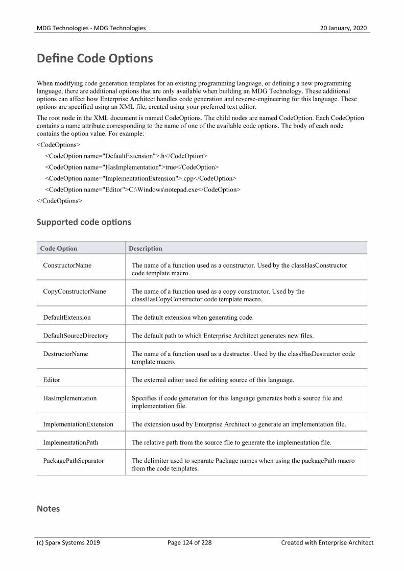
MDG Technologies - MDG Technologies 20 January, 2020
Define Code Options
When modifying code generation templates for an existing programming language, or defining a new programminglanguage, there are additional options that are only available when building an MDG Technology. These additionaloptions can affect how Enterprise Architect handles code generation and reverse-engineering for this language. Theseoptions are specified using an XML file, created using your preferred text editor.
The root node in the XML document is named CodeOptions. The child nodes are named CodeOption. Each CodeOptioncontains a name attribute corresponding to the name of one of the available code options. The body of each nodecontains the option value. For example:
<CodeOptions>
<CodeOption name="DefaultExtension">.h</CodeOption>
<CodeOption name="HasImplementation">true</CodeOption>
<CodeOption name="ImplementationExtension">.cpp</CodeOption>
<CodeOption name="Editor">C:\Windows\notepad.exe</CodeOption>
</CodeOptions>
Supported code options
Code Option Description
ConstructorName The name of a function used as a constructor. Used by the classHasConstructorcode template macro.
CopyConstructorName The name of a function used as a copy constructor. Used by theclassHasCopyConstructor code template macro.
DefaultExtension The default extension when generating code.
DefaultSourceDirectory The default path to which Enterprise Architect generates new files.
DestructorName The name of a function used as a destructor. Used by the classHasDestructor codetemplate macro.
Editor The external editor used for editing source of this language.
HasImplementation Specifies if code generation for this language generates both a source file andimplementation file.
ImplementationExtension The extension used by Enterprise Architect to generate an implementation file.
ImplementationPath The relative path from the source file to generate the implementation file.
PackagePathSeparator The delimiter used to separate Package names when using the packagePath macrofrom the code templates.
Notes
(c) Sparx Systems 2019 Page 124 of 228 Created with Enterprise Architect

MDG Technologies - MDG Technologies 20 January, 2020
Once a language is available for use in a model (by importing and activating the MDG Technology), you can display·and edit the code options on the 'Preferences' dialog ('Start > Desktop > Preferences > Preferences')
(c) Sparx Systems 2019 Page 125 of 228 Created with Enterprise Architect

MDG Technologies - MDG Technologies 20 January, 2020
Add MDA Transforms
When creating an MDG Technology file, you can include any MDA Transformation templates that you have created ormodified in the model and that you want to deploy as part of the technology.
Access
Ribbon Specialize > Technologies > Publish-Tech > Generate MDG Technology
Add MDA Transformation Templates to the MDG Technology File
Step Description
1 Follow the steps in the Create MDG Technologies topic up to and including Step 6, where you select the'MDA Transforms' checkbox.
The 'MDG Technology Wizard - Transform Modules' page displays, listing the MDA transform templatesavailable on your system.
2 Click the checkbox against the name of each transformation template you want to add to your MDGTechnology.
3 Click on the Next button to proceed.
(c) Sparx Systems 2019 Page 126 of 228 Created with Enterprise Architect
MDG Technologies - MDG Technologies 20 January, 2020
Add Document Report Templates
When creating an MDG Technology file, you can include user-defined Document Report templates.
Access
Ribbon Specialize > Technologies > Publish-Tech > Generate MDG Technology
Add Report Templates to the MDG Technology File
Step Description
1 Follow the steps in the Create MDG Technologies topic up to and including Step 6, where you select the'RTF Templates' checkbox.
The 'MDG Technology Wizard - RTF Report Templates' dialog displays.
2 For each required user-defined report template available in the current model, select the checkbox next tothe template name.
3 Click on the Next button to proceed.
(c) Sparx Systems 2019 Page 127 of 228 Created with Enterprise Architect

MDG Technologies - MDG Technologies 20 January, 2020
Add Linked Document Templates
When creating an MDG Technology file, you can include Linked Document templates.
Access
Ribbon Specialize > Technologies > Publish-Tech > Generate MDG Technology
Add Linked Document Templates to the MDG Technology File
Step Description
1 Follow the steps in the Create MDG Technologies topic up to and including Step 6, where you select the'Linked Document Templates' checkbox.
The 'MDG Technology Wizard - Linked Document Templates' dialog displays.
2 For each required document template available in the current model, select the checkbox next to thetemplate name.
3 Click on the Next button to proceed.
(c) Sparx Systems 2019 Page 128 of 228 Created with Enterprise Architect

MDG Technologies - MDG Technologies 20 January, 2020
Add Images
When creating an MDG Technology file, you can incorporate images to be used in all models in which the technology isdeployed. These images must already be available in the model in which the technology is being developed; you canimport the images into this model using the Add New button on the Image Manager.
Access
Ribbon Specialize > Technologies > Publish-Tech > Generate MDG Technology
Add Images to the MDG Technology File
Step Description
1 Follow the steps in the Create MDG Technologies topic up to and including Step 6, where you select the'Images' checkbox.
The 'MDG Technology Wizard - Image Selection' dialog displays.
2 For each required model image available in the current model, select the checkbox next to the imagename.
A preview of each image displays on the right of the dialog as you select the checkbox.
3 Click on the Next button to proceed.
(c) Sparx Systems 2019 Page 129 of 228 Created with Enterprise Architect

MDG Technologies - MDG Technologies 20 January, 2020
Add Scripts
When creating an MDG Technology file, you can include scripts that you have created in the model.
Access
Ribbon Specialize > Technologies > Publish-Tech > Generate MDG Technology
Add Scripts to the MDG Technology File
Step Description
1 Follow the steps in the Create MDG Technologies topic up to and including Step 6, where you select the'Scripts' checkbox.
The 'MDG Technology Wizard - Scripts' dialog displays.
2 For each required script available in the current model, select the checkbox next to the script name.
3 Click on the Next button to proceed.
Notes
This facility is available in the Corporate, Unified and Ultimate editions of Enterprise Architect·
(c) Sparx Systems 2019 Page 130 of 228 Created with Enterprise Architect

MDG Technologies - MDG Technologies 20 January, 2020
Add Workspace Layouts
When developing an MDG Technology file, you can include user-defined workspace layouts. Workspace layouts arearrangements of toolbars and windows appropriate to an area of work such as Requirements Management and CodeEngineering. The workspace layout automatically opens and organizes all the tools to suit the way in which you use thesystem.
Access
Ribbon Specialize > Technologies > Publish-Tech > Generate MDG Technology
Add Workspace Layouts to the MDG Technology File
Step Description
1 In your model, create the workspace layouts you want to include in your Technology.
2 Follow the steps in the Create MDG Technologies topic up to and including Step 6, where you select the'Workspace Layouts' checkbox.
The 'MDG Technology Wizard - Workspace Layouts' dialog displays, listing the user-defined workspacelayouts available to you.
3 For each workspace layout that you want to incorporate in the Technology, select the checkbox next to thelayout name.
4 Click on the Next button to proceed.
(c) Sparx Systems 2019 Page 131 of 228 Created with Enterprise Architect

MDG Technologies - MDG Technologies 20 January, 2020
Add Model Views
When developing an MDG Technology file, you can include user-defined Model Views. Model Views are based onsearches that extract specific information from a model to provide different perspectives of, and 'entry points' into, themodel.
Access
Ribbon Specialize > Technologies > Publish-Tech > Generate MDG Technology
Add Model Views to the MDG Technology File
Step Description
1 In your model, create the Model Views you want to include in your Technology.
2 Follow the steps in the Create MDG Technologies topic up to and including Step 6, where you select the'Model Views' checkbox.
The 'MDG Technology Wizard - Model Views' dialog displays, listing the user-defined views available inthe current model.
3 For each Model View that you want to incorporate in the Technology, select the checkbox next to theview name.
4 Click on the Next button to proceed.
Notes
Technology views do not store Favorite Packages, only Views·
If you incorporate a Model View that runs searches that you have defined, you must also include those searches in·your MDG Technology
(c) Sparx Systems 2019 Page 132 of 228 Created with Enterprise Architect

MDG Technologies - MDG Technologies 20 January, 2020
Add Model Searches
When developing an MDG Technology file, you can include user-defined Model Searches. You can set these searches upusing the Model Search facility, in SQL, in the Query Builder or as an Add-In, and then link them into your MDGTechnology.
Access
Ribbon Specialize > Technologies > Publish-Tech > Generate MDG Technology
Add Model Searches to the MDG Technology File
Step Description
1 In your model, create the Model Searches you want to include in your Technology.
2 Follow the steps in the Create MDG Technologies topic up to and including Step 6, where you select the'Model Searches' checkbox.
The 'MDG Technology Wizard - Model Searches' dialog displays, listing the user-defined searchesavailable in the current model.
3 For each Model Search that you want to incorporate in the Technology, select the checkbox next to thesearch name.
4 Click on the Next button to proceed.
Notes
If you use a custom SQL search, the SQL must include ea_guid AS CLASSGUID and the object type·
If you incorporate a Model View that runs searches that you have defined, you must also include those searches in·your MDG Technology
(c) Sparx Systems 2019 Page 133 of 228 Created with Enterprise Architect

MDG Technologies - MDG Technologies 20 January, 2020
Working with MTS Files
When you are creating an MDG Technology File using the MDG Technology Wizard, you have the choice of storing allof the options and structures that you have defined in an MDG Technology Selection (.mts) file. This captures all theinformation you enter into the Technology Wizard, so that you do not have to type it in again. If you use a .mts file, youcan subsequently edit it to change the features you selected when you generated the Technology file, and to add orremove additional, advanced features.
Access
Ribbon Specialize > Technologies > Publish-Tech > Generate MDG Technology
Manage the .MTS file
Action Description
Create a .MTS File To create a .mts file, launch and work through the MDG Technology Wizard; onthe second page, select the 'Create a new MTS file' option.
Advanced Options ForYour .MTS File
Once you have worked through the MDG Technology Wizard and set up the .mtsfile, you can add, separately:
Model Validation configurations·
Model Templates·
Firstly define the XMI for the model validation configurations and modeltemplates, then open the .mts file in a text editor and copy in the validation and/ortemplate description just before the </MDG.Selections> line.
Save the .mts file.
Update the MDGTechnology
Again launch the MDG Technology Wizard, but this time on the second page selectthe 'Open an Existing MTS file' option and specify the file path of the .mts file youhave been working on.
Click on the Next button until the Wizard is finished; your MDG Technology .xmlfile is updated.
Notes
Having created your MDG Technology with the Wizard and the .mts file, you can add Import and Export scripts via·the Technology .xml file
(c) Sparx Systems 2019 Page 134 of 228 Created with Enterprise Architect

MDG Technologies - MDG Technologies 20 January, 2020
Create Toolbox Profiles
As a facility of your MDG Technology, you might want to provide Diagram Toolbox pages that give access to anyelements and connectors that you have created within the technology. You define these Toolbox pages within specificProfiles, each Profile defining the element and connector Toolbox pages that open or can be selected for a diagram type.
Create custom Toolboxes
Step Action
1 Create a set of Toolbox Profiles that contain the definitions required to generate the Toolbox pages.
2 Edit the definitions, where appropriate, to:
Include hidden sub-menus·
Override the default Toolboxes·
Change the default icons for Toolbox items·
3 Create a .mts file containing instructions on how to build your MDG Technology, and include theToolbox Profiles in the technology.
(c) Sparx Systems 2019 Page 135 of 228 Created with Enterprise Architect

MDG Technologies - MDG Technologies 20 January, 2020
Create Toolbox Profiles
Within an MDG Technology you can create multiple Toolbox Profiles. Each Toolbox Profile contains definitions thatdetermine what pages appear in the Diagram Toolbox when it is opened, either by selection from the search facilities inthe Diagram Toolbox, or by opening or creating a diagram of the type that is linked to the Toolbox Profile.
Toolbox Profile Errors
When a Diagram Toolbox defined in your MDG Technology is in use, certain error messages might be displayed. Thistable explains what those error messages mean.
Message Meaning
Missing base type <name> For example: 'Missing base type: 'SysML1.3::Block' does not extend 'UML::State'
The base type is either missing or does not correspond to the extended element type(in the example, SysML::Block actually extends UML::Class).
No profile found with id<name>
This error message could mean that the profile cannot be found, or that the MDGTechnology containing the profile has been disabled (check using 'Specialize>Technologies > Manage').
No stereotype <name>found in profile <name>
For example: 'No stereotype 'ProxyPort' found in profile 'SysML 1.2'.
This message indicates that there is a mismatch between the stereotype required andthe profile it is supposed to be in. In the example, SysML1.2 does not haveProxyPorts, so perhaps the stereotype should be 'FlowPort', or the profile 'SysML1.3'.
Unknown/Illegal base type:<name>
There can be a number of reasons for this message being displayed. For example:
Unknown/Illegal base type: UML::Capability - displayed because there is no·such UML metaclass as 'Capability'
Unknown/Illegal base type: SysML 1.3::Block - displayed because you are·trying to extend a stereotype from another profile, in this case <<Block>> fromthe SysML 1.3 profile; you must extend the same thing as the stereotype youare specializing extends (in this case 'UML::Class')
Create a Toolbox Profile
Step Action
1 In a Profile Package, create a Class diagram with an appropriate name by which you can refer to it later,such as MyClassDiagram.
2 Double-click on the diagram background to display the diagram 'Properties' dialog and, in the 'Notes'field, give the diagram an alias and a description in this format:
Alias=MyClass;Notes=Structural elements for Class diagrams;
3 On the diagram, create a Metaclass element with the name ToolboxPage.
(c) Sparx Systems 2019 Page 136 of 228 Created with Enterprise Architect

MDG Technologies - MDG Technologies 20 January, 2020
4 Create a Stereotype element for each of the Toolbox pages to create within your Toolbox, such asMyClassElements and MyClassRelationships.
Double-click on each element to display the 'Properties' dialog and, in the 'Alias' field, type the text todisplay in the title bar of the corresponding Toolbox page, such as My Classes or My Class Relationships.
In the 'Notes' field of each element, type the tool-tip for the corresponding Toolbox page; for example,'Elements for Class Diagrams' or 'Relationships for Class Diagrams'.
Create an Extension connector between each Stereotype element and the ToolboxPage Metaclass element.
5 In each of the Stereotype elements, press F9 and create an attribute for each Toolbox item in the pagedefined by that element.
The name of each attribute is the name of the element or connector to be dropped, including the element'snamespace; for example, UML::Package, UML::Class and UML::Interface. You might not want todisplay names including text such as UML::Package or UML::Class in your Toolbox, so give theattributes an 'Initial Value' of, for example, Package or Class.
The Toolbox items display in the same sequence as their attributes in the element, so use the attributeordering options in the 'Attributes' page of the Features window to define the order of icons in yourToolbox page.
In the name of an attribute for an element or connector from your own technology, use your Profile nameas the namespace, and then follow the item name with the element or connector type that you areextending, in brackets (to identify to Enterprise Architect what type of object to create); for example, aSysML Block element would appear as:
SysML::Block(UML::Class)
Many elements and connectors can be extended for use in Toolboxes.
6 To define a Toolbox item to drop a Design Pattern onto a diagram, name the attribute:
My Technology::MyPattern(UMLPattern)
'MyTechnology' is the ID of the technology and 'MyPattern' is the name of the Pattern to drop; forexample:
BusFramework::Builder(UMLPattern)
If you want to avoid displaying the 'Add Pattern' dialog, replace (UMLPattern) with (UMLPatternSilent).
To define a model-based Pattern in a custom Toolbox (such as the GoF Patterns), create an attribute witha name of the format:
PatternCategory::PatternName(UMLPattern)
For example:
GoF::Mediator(UMLPattern)
7 Define any attributes you need to modify the display of the Toolbox pages, such as whether the Toolboxpages are minimized or displayed without item names (labels).
8 To save the Toolbox profile, click on the background of the open diagram and select either of the ribbonoptions:
Design > Diagram > Manage > Save as Profile or·
Specialize > Technologies > Publish-Tech > Publish Diagram as UML Profile·
Notes
When assigning an Alias for a Toolbox page, 'elements' is a reserved word; if the word 'elements' is used, it will not·appear in the title bar of the corresponding Toolbox page
(c) Sparx Systems 2019 Page 137 of 228 Created with Enterprise Architect

MDG Technologies - MDG Technologies 20 January, 2020
Each Profile element incorporated into an MDG Toolbox page enables a context menu option to synchronize the·Tagged Values and Constraints of all objects created from it
The sequence of Toolbox pages in the Toolbox is determined by the sequence of their Stereotype elements in the·Profile diagram or Profile Package; if you create and save the Profile from a: - Diagram, the Toolbox page sequence is determined by the Z-order of the Stereotype elements on the diagram - the lower (closer to 1) the Z-order number of the Stereotype element (the closer it is to the 'surface' of the diagram), the further down the Toolbox its Toolbox page is placed; if you change the Z-order of a Stereotype element in the diagram, it changes the position of the element's page on the Toolbox - Package in the Browser window, the Toolbox page sequence is determined by the list order of the Stereotype elements in the Package - the Toolbox page for the first listed element is at the top of the Toolbox; if you re-order the elements in the Browser window, you produce the same re-ordering of pages in the Toolbox
(c) Sparx Systems 2019 Page 138 of 228 Created with Enterprise Architect

MDG Technologies - MDG Technologies 20 January, 2020
Toolbox Page Attributes
When you create a Stereotype element to define a Toolbox page in an MDG Technology, you can add a number ofattributes to control how the page itself behaves in the Diagram Toolbox. The Stereotype element can be one of severalthat extend the ToolboxPage Metaclass.
The attributes you can add are:
Icon - see Assign Icons To Toolbox Items·
ImagesOnly - if you set Initial Value to true, the Toolbox page displays without the text labels next to the icons·
isCollapsed - if you set Initial Value to true, the Toolbox page is initially minimized·
isCommon - if you set Initial Value to true, the Toolbox page is common to all defined Toolboxes while your·technology is active; the page is initially displayed as collapsed
isHidden - see Create Hidden Sub-Menus·
(c) Sparx Systems 2019 Page 139 of 228 Created with Enterprise Architect
MDG Technologies - MDG Technologies 20 January, 2020
Create Hidden Sub-Menus
When you create items on a Toolbox page, some of them might be very similar and be based on the same type ofMetaclass. For example, there are many different types of Action element and, in BPMN 2.0, you can create each type ofEvent element either stand-alone or edge-mounted on another element. Rather than populate a Toolbox page with everyvariation, you can create a 'base' Toolbox item and offer a choice of variant from a sub-menu, which is displayed whenthe base item is dragged onto the diagram but is otherwise hidden. This technique is very useful for 'disambiguating'Stereotypes that can be applied to multiple Metaclasses.
In the submenu, you define just the variant types (as for the Action element list). However, if the variant also has aToolboxItemImage defined for it, that icon is displayed against the variant name in the sub-menu (as for the BPMN 2.0Events). You can also use this method to specifically define icons that will be applied to the submenu options.
Define a hidden sub-menu
Step Action
1 Create a Stereotype element on the same diagram as the ToolboxPage Metaclass, with a name prefixed bythe Profile name (this is mandatory). For example:
MyProfile::MyClass
The name must not match the name of any external stereotype that exists in any other Profile.
The sub-menu element can have an alias.
2 In this sub-menu Stereotype element, create the attribute isHidden with an initial value of True.
For each sub-menu item, add an attribute to identify that item. Set the 'Initial Value' to the name to displayin the menu. For example, if the «MyClass» stereotype could be applied to a UML Class or UMLInterface, the attributes for these two options would be:
MyProfile::MyClass(UML::Class) Initial Value = Class
MyProfile::MyClass(UML::Interface) Initial Value = Interface
3 Create a second Stereotype element and define an attribute with the same name as the sub-menuStereotype element, and with the initial value of the text to display in the Toolbox item. For example:
MyProfile::MyClass = Class Object
Define additional attributes for the rest of the items in the Toolbox, as normal.
4 Create <<Extension>> relationships between each Stereotype element and the ToolboxPage Metaclasselement, as illustrated.
(c) Sparx Systems 2019 Page 140 of 228 Created with Enterprise Architect
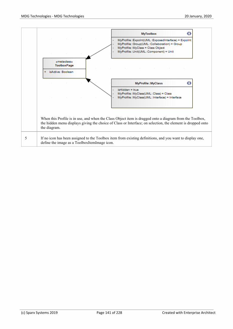
MDG Technologies - MDG Technologies 20 January, 2020
When this Profile is in use, and when the Class Object item is dragged onto a diagram from the Toolbox,the hidden menu displays giving the choice of Class or Interface; on selection, the element is dropped ontothe diagram.
5 If no icon has been assigned to the Toolbox item from existing definitions, and you want to display one,define the image as a ToolboxItemImage icon.
(c) Sparx Systems 2019 Page 141 of 228 Created with Enterprise Architect

MDG Technologies - MDG Technologies 20 January, 2020
Assign Icons To Toolbox Items
When you create a stereotyped model element to define an element or connector that is represented in a DiagramToolbox page, you can define the image that is displayed against both the element name in the Browser window and theelement or connector type in the Toolbox page, by assigning the special attribute icon to the Stereotype element.
This image definition for the Toolbox item can be overridden or replaced by extending the ToolboxItemImageMetaclass, a process that is generally optional. However, if you want to show an icon against an item on a hiddensub-menu, you must use this method; the system picks up the ToolboxItemImage definition as the icon for the hiddenmenu item.
If you do not use either the icon attribute or the ToolboxItemImage Metaclass to define the Toolbox icon, the imagedefaults to the one used for the standard UML model element that has been extended. If there is no such image, the iconuses the system default generic 'Toolbox Item' image.
Extend the ToolboxItemImage Metaclass
Step Action
1 Create a new Stereotype element in the same Toolbox profile as the Toolbox item.
2 Give the Stereotype element the same name as the element that it is assigning an image to; for example:
MyProfile::MyStereo(UML::Class)
3 Give the Stereotype element the special attribute Icon with Initial Value set to the full path and file nameof the image to be used.
The icon image is a 16x16 pixel bitmap file; for a transparent background use light gray -RGB(192,192,192).
4 Create a Metaclass element named ToolboxItemImage and create an Extension association from theStereotype element to this Metaclass.
(c) Sparx Systems 2019 Page 142 of 228 Created with Enterprise Architect

MDG Technologies - MDG Technologies 20 January, 2020
(c) Sparx Systems 2019 Page 143 of 228 Created with Enterprise Architect

MDG Technologies - MDG Technologies 20 January, 2020
Override Default Toolboxes
When you are creating a diagram of one of the inbuilt diagram types, the system displays a Diagram Toolbox based onthe corresponding default Toolbox Profile. If you have customized a diagram type, it will still apply the system defaultToolbox for the base diagram type that you have extended, unless you override that default with an alternative Toolboxthat you might have created yourself. For example, you might have your own version of the UML::Class Toolbox thatyou want to be displayed every time a Class diagram is opened, when your technology is active.
Note that for the default Toolboxes to be overridden by the custom Toolboxes in your MDG Technology, the MDGTechnology must be set to 'Active'. ('Specialize > Technologies > Manage-Tech', then select the checkbox against yourMDG Technology name and click on the Set Active button.)
Access
To replace a system default Toolbox with one of your own:
Use one of the methods outlined here to display the 'Properties' dialog for your Toolbox Profile diagram, and display the'General' tab.
Then, in the 'Notes' field type a RedefinedToolbox clause.
For example:
RedefinedToolbox=UML::Class;Alias=Class;Notes=Structural elements for Class diagrams;
This states that the Toolbox defined by this Profile replaces the system Toolbox UML::Class as the default Toolbox forall UML Class diagrams.
Ribbon Design > Diagram > Manage > Properties > General
Context Menu Right-click on the Toolbox Profile diagram | Properties | General
Names of system default toolboxes that can be overridden
UML::Activity·
UML::Class·
UML::Communication·
UML::Component·
UML::Composite·
UML::Deployment·
UML::Interaction·
UML::Metamodel·
UML::Object·
UML::Profile·
UML::State·
UML::Timing·
UML::UseCase·
Extended::Analysis·
Extended::Custom·
(c) Sparx Systems 2019 Page 144 of 228 Created with Enterprise Architect

MDG Technologies - MDG Technologies 20 January, 2020
Extended::DataModeling·
Extended::Maintenance·
Extended::Requirements·
Extended::UserInterface·
Extended::WSDL·
Extended::XMLSchema·
(c) Sparx Systems 2019 Page 145 of 228 Created with Enterprise Architect

MDG Technologies - MDG Technologies 20 January, 2020
Elements Used in Toolboxes
When you are creating Toolbox pages for your MDG Technology, you can incorporate both standard UML elements andnew elements that you have created by extending the UML elements. You define the elements you want to use in theToolbox Profile. The table lists the names you use to identify either:
The standard elements to include in the Toolbox page or·
The standard elements you are extending to define new elements to include in the Toolbox page·
Each name you list in the Toolbox Page Stereotype elements is preceded by the namespace UML::. The text inparentheses indicates the label name displayed in the default Toolbox pages, where this differs in any way from theUML:: statement text.
Element names for Toolbox Page definitions
Action·
ActionPin·
Activity·
ActivityFinal (Final)·
ActivityInitial (Initial)·
ActivityParameter·
ActivityPartition (Partition)·
ActivityRegion (Region)·
Actor·
Artifact·
AssociationElement (Association)·
Boundary (for Use Cases)·
CentralBufferNode (Central Buffer Node)·
Change·
Choice·
Class·
Collaboration·
CollaborationOccurrence (Collaboration Use)·
Comment (Note)·
Component·
Constraint·
Datastore·
Decision·
DeploymentSpecification (Deployment Specification)·
Device·
DiagramLegend (Diagram Legend)·
DiagramNotes (Diagram Notes)·
DocumentArtifact (Document Artifact or Document)·
Entity (Information)·
EntityObject (Entity)·
(c) Sparx Systems 2019 Page 146 of 228 Created with Enterprise Architect

MDG Technologies - MDG Technologies 20 January, 2020
EntryPoint (Entry)·
Enumeration·
ExceptionHandler (Exception)·
ExecutionEnvironment (Execution Environment)·
ExpansionRegion·
ExitPoint (Exit)·
Feature·
FinalState (Final)·
FlowFinalNode (Flow Final)·
ForkJoinH (Fork/Join - Horizontal)·
ForkJoinV (Fork/Join - Vertical)·
Gate (Diagram Gate)·
GUIElement (UI Control)·
HistoryState (History)·
Hyperlink·
InformationItem (Information Item)·
InitialState (Initial)·
Interaction·
InteractionFragment (Fragment)·
InteractionState (State/Continuation)·
Interface·
InterruptibleActivityRegion·
Issue·
Junction·
Lifeline·
MergeNode (Merge)·
MessageEndPoint (Endpoint or Message Endpoint)·
MessageLabel (Message Label)·
Metaclass·
Node·
Object·
ObjectBoundary (Boundary)·
ObjectControl (Control)·
ObjectEntity (Entity)·
Package·
PackagingComponent·
Part·
Port·
Primitive·
PrimitiveType·
Process·
Profile·
(c) Sparx Systems 2019 Page 147 of 228 Created with Enterprise Architect

MDG Technologies - MDG Technologies 20 January, 2020
ProvidedInterface (Expose Interface)·
ReceiveEvent (Receive)·
Requirement·
RobustBoundary (Boundary)·
RobustControl (Control)·
RobustEntity (Entity)·
Screen·
SendEvent (Send)·
SequenceBoundary (Boundary)·
SequenceControl (Control)·
SequenceEntity (Entity)·
Signal·
State·
StateMachine (StateMachine)·
StateTimeLine (State Lifeline)·
Stereotype·
StructuredActivity (Structured Activity)·
SynchState (Synch)·
Table·
Terminate·
TestCase (Test Case)·
Text·
UseCase (Use Case)·
UMLBoundary (Boundary)·
ValueTimeLine (Value Lifeline)·
Notes
You can also identify standard or extended UML connectors to add to the Toolbox Page definition·
When the element items are deployed in an MDG Toolbox page, you can also synchronize the Tagged Values and·Constraints of all elements created from them
(c) Sparx Systems 2019 Page 148 of 228 Created with Enterprise Architect

MDG Technologies - MDG Technologies 20 January, 2020
Connectors Used in Toolboxes
When you are creating Toolbox pages for your MDG Technology, you can incorporate both standard UML connectorsand new connectors that you have created by extending the UML connectors. You define the connectors you want to usein the Toolbox Profile. The Connector names for Toolbox Page definitions table lists the names you use to identifyeither:
The standard connectors to include in the Toolbox page or·
The standard connectors you are extending to define new connectors to include in the Toolbox page·
Each name you list in the 'Toolbox Page Stereotype elements' is preceded by the namespace UML::. The text in bracketsindicates the label name displayed in the default Toolbox pages, where this differs in any way from the UML:: statementtext.
Connector names for Toolbox Page definitions
Abstraction·
Aggregation (Aggregate)·
Assembly·
Association (Associate)·
AssociationClass (Association Class)·
CallFromRecursion (Call)·
CommunicationPath (Communication Path)·
Composition (Compose)·
Connector·
ControlFlow (Control Flow)·
Delegate·
Dependency·
Deployment·
Extension·
Generalization (Generalize or Inheritance)·
InformationFlow (Information Flow)·
InterruptFlow (Interrupt Flow)·
Invokes·
Manifest·
Message·
Nesting·
NoteLink (Note Link)·
ObjectFlow (Object Flow)·
Occurrence·
PackageImport (Package Import)·
PackageMerge (Package Merge)·
Precedes·
ProfileApplication (Application)·
Realization (Realize or Implements)·
(c) Sparx Systems 2019 Page 149 of 228 Created with Enterprise Architect

MDG Technologies - MDG Technologies 20 January, 2020
Recursion·
Redefinition·
Representation·
Represents·
RoleBinding (Role Binding)·
SelfMessage (Self-Message)·
Substitution·
TagValAssociation (Tagged Value)·
TemplateBinding (Template Binding)·
TraceLink (Trace)·
Transition·
UCExtend (Extend)·
UCInclude (Include)·
Usage·
UseCaseLink (Use)·
Notes
You can also identify standard or extended UML elements to add to the Toolbox Page definition·
(c) Sparx Systems 2019 Page 150 of 228 Created with Enterprise Architect

MDG Technologies - MDG Technologies 20 January, 2020
Create Custom Diagram Profiles
When you develop an MDG Technology, it is possible to create extended diagram types and include them in your MDGTechnology as custom Diagram Profiles. For example, you might create a DFD Diagram Profile that defines a DFDdiagram as an extension of the built-in Analysis diagram, as shown:
Create extended diagram types
Step Action
1 Create a Profile, with the same name as the MDG Technology in which it is to be included; for example,SysML.
This Profile automatically contains one child Class diagram. Depending on how many new diagram typesyou intend to create, you can define:
One diagram type on one child diagram·
Several diagram types on one diagram, or·
Several diagram types grouped on several diagrams·
In the third case, create any further child Class diagrams you need. The diagram names do not have toreflect the technology name.
2 Open the child Class diagram and create a Stereotype element, giving it the name of the Custom diagramtype; for example, BlockDefinition.
Also on the Stereotype element 'Properties' dialog, in the 'Notes' field, type a brief description of what thediagram is used for.
When the Technology is deployed and a diagram of this Custom type is being created, this descriptionwill display in the bottom right-hand corner of the 'New Diagram' dialog.
3 Create a Metaclass element and give it the name of the selected built-in diagram type, with the prefixDiagram_.
For example Diagram_Logical to customize the Class diagram type, or Diagram_Use Case to customizethe Use Case diagram type.
4 Drag an Extension connector from the Stereotype element to the Metaclass element.
5 Click on the Diagram_xxxx Metaclass element, press F9 and create any or all of these attributes, to setproperties of the Custom diagram type:
alias: string = Type (where Type will appear before the word 'Diagram' on the diagram title bar; for·example, 'Block Diagram')
diagramID: string = abc (where abc is the diagram type that will appear in the diagram frame label)·
toolbox: string = ToolboxName (where ToolboxName is the name of the Toolbox Profile for the·
(c) Sparx Systems 2019 Page 151 of 228 Created with Enterprise Architect

MDG Technologies - MDG Technologies 20 January, 2020
Toolbox that opens automatically each time a diagram of this type is opened)
toolboxPage: string = list of status values in the form "PageName=1;" (where PageName is the name·of the stereotype element that extends ToolboxPage; if this string is not empty, all toolbox pages withthe value "1" will be expanded and all other toolbox pages will be collapsed)
frameString: string = FrameFormatString (where FrameFormatString is a string containing·substitution macros for defining the frame title, with or without additional delimiters such as ();macros that can be used are: - #DGMALIAS# - #DGMID# - #DGMNAME# - #DGMNAMEFULL# - #DGMOWNERNAME# - #DGMOWNERNAMEFULL# - #DGMOWNERTYPE# - #DGMSTEREO# - #DGMTYPE#
swimlanes: string = Lanes=2;Orientation=Horizontal;Lane1=Title1;Lane2=Title2; (where Lanes can·be any value, but the number of Lane<n> values must equal the value of Lanes; Orientation can beomitted, in which case the swimlanes default to vertical)
styleex: string = one or more of a range of values·
pdata: string = one or more of a range of values·
6 Depending on what Profile Package organization you adopted at step 1, and whether you need any furtherStereotype-Metaclass element pairs, repeat steps 2 - 5 on this diagram or on another child diagram.
7 Save the diagram(s) as a Diagram Profile, using the method most appropriate to the Profile Packageorganization you have set up.
8 Add the Diagram Profile(s) to the .mts file used in the MDG Technology.
(c) Sparx Systems 2019 Page 152 of 228 Created with Enterprise Architect

MDG Technologies - MDG Technologies 20 January, 2020
Built-In Diagram Types
In customizing Enterprise Architect to better suit your needs, you might create a Profile that:
Redefines the type of built-in child diagram created under a new composite element·
Defines the types of built-in diagram on which a Quick Linker menu offers a type of connector, or·
Extends a built-in diagram type to create a custom diagram type·
In each case, you provide the precise name of each built-in diagram type you are working with; these names are:
Activity·
Analysis·
Collaboration·
Component·
CompositeStructure·
Custom·
Deployment·
InteractionOverview·
Logical (for Class diagrams)·
Object·
Package·
Sequence·
Statechart·
Timing·
Use Case (note the space between the two words)·
(c) Sparx Systems 2019 Page 153 of 228 Created with Enterprise Architect

MDG Technologies - MDG Technologies 20 January, 2020
Attribute Values - styleex & pdata
When creating a diagram profile you can define a range of characteristics of the diagrams created with the profile, usingthe pdata and styleex attributes. If one of these attributes is defining several characteristics at once, you put the values ina single string separated by semicolons; for example:
HideQuals=0;AdvanceElementProps=1;ShowNotes=1;
Access
Select the Metaclass element, then display the 'Attributes' dialog and define or update the attributes 'styleex' or 'pdata'.
Specify the attribute type as 'string', then specify the diagram characteristics you require, in the 'Initial Value' field.
Use any of these methods to display the 'Attributes' dialog.
Ribbon Design > Element > Editors > Attributes
Context Menu In the Browser window or a diagram | Right-click on Metaclass element | Features |Attributes
Keyboard Shortcuts F9
styleex: string =
AdvancedConnectorProps=1; (to show connector property strings)·
AdvancedElementProps=1; (to show the element property string)·
AdvancedFeatureProps=1; (to show the feature property string)·
AttPkg=1; (to show Package visible Class members)·
DefaultLang=Language; (to set the default language for the diagram; Language can be one of the built-in languages·such as C++ or Java, or it can be a custom language)
ExcludeRTF=1; (to exclude the diagram image from generated reports)·
HandDraw=1; (to apply hand drawn mode)·
HideConnStereotype=1; (to hide the connector stereotype labels)·
HideQuals=0; (to show qualifiers and visibility indicators)·
NoFullScope=1; (to hide fully scoped element names, e.g. "ParentClass::ChildClass" will be shown as "ChildClass")·
SeqTopMargin=50; (to set the height of the top margin on Sequence diagrams)·
ShowAsList=1; (to make the diagram open directly into the Diagram List)·
ShowMaint=1; (to show the element Maintenance compartment)·
ShowNotes=1; (to show the element Notes compartment)·
ShowOpRetType=1; (to show the operation return type)·
ShowTests=1; (to show the element Testing compartment)·
SuppConnectorLabels=1; (to suppress all connector labels)·
SuppressBrackets=1; (to suppress brackets on operations without parameters)·
TConnectorNotation=Option; (where Option is one of UML 2.1, IDEF1X, or Information Engineering)·
(c) Sparx Systems 2019 Page 154 of 228 Created with Enterprise Architect

MDG Technologies - MDG Technologies 20 January, 2020
TExplicitNavigability=1; (to show non-navigable connector ends)·
VisibleAttributeDetail=1; (to show attribute details on the diagram)·
Whiteboard=1; (to apply whiteboard mode)·
pdata: string =
HideAtts=0; (to show the element Attributes compartment)·
HideEStereo=0; (to show element stereotypes in the diagram)·
HideOps=0; (to show the element Operations compartment)·
HideParents=0; (to show additional parents of elements in the diagram)·
HideProps=0; (to show property methods)·
HideRel=0; (to show relationships)·
HideStereo=0; (to show attribute and operation stereotypes)·
OpParams =3; (to show operation parameters)·
ShowCons=1; (to show the element Constraints compartment)·
ShowIcons=1; (to use stereotype icons)·
ShowReqs=1; (to show the element Requirements compartment)·
ShowSN=1; (to show sequence notes)·
ShowTags=1; (to show the element Tagged Values compartment)·
SuppCN=0; (to show collaboration numbers)·
UseAlias=1; (to use the aliases or elements in the diagram, if available)·
(c) Sparx Systems 2019 Page 155 of 228 Created with Enterprise Architect

MDG Technologies - MDG Technologies 20 January, 2020
Set Up Technology Element Images
As you define the elements available for use in your technology, you might want to represent those elements withgraphical images that will be displayed on the diagrams the users create through the technology, when it is deployed inthe users' model.
Capture images to represent MDG Technology elements
Step Action
1 Display the Image Manager and, using the Add New button, import suitable images into the MDGTechnology development model from their source locations.
2 Design and create a Stereotype (UML) Profile containing (if appropriate) a stereotype definition for eachelement or connector to be owned by the technology.
These stereotype definitions can contain Shape Scripts that in turn incorporate the imported images.
3 Design and create a Toolbox Profile with stereotype elements that contain an attribute for each element orconnector that can be dropped onto a diagram from the Toolbox.
These attributes identify the name of the technology element or connector, any modifying stereotype(which might incorporate the required image) and the UML or Extended element or connector on whichthe technology object is based.
For example:
SysML::Block(UML::Class)
SysML is the Technology Profile·
UML::Class is the UML element used as the base, and·
Block is the stereotype that modifies the Class to turn it into a SysML Block element·
4 Design and create a Diagram Profile that identifies the Toolbox Profile.
When a diagram of the type defined in the Diagram Profile is opened, it in turn opens a set of toolboxpages as defined by the Toolbox Profile.
5 Create or update the technology as required, adding the UML Profile, Diagram Profile, Toolbox Profileand Image files to the technology from the development model.
6 Deploy the technology as appropriate.
When a user applies the technology to their own model, and creates a diagram under that technology, theelements they create on the diagram should be represented by the images you assigned to those elementswhen you created the technology.
Notes
It is recommended that if you create a Shape Script incorporating an MDG Technology image (step 2), you should·use the fully qualified image name to avoid conflicts with images used in other technologies
You would probably work backwards and forwards through the steps many times, adding objects as you identify the·requirement for them
(c) Sparx Systems 2019 Page 156 of 228 Created with Enterprise Architect

MDG Technologies - MDG Technologies 20 January, 2020
(c) Sparx Systems 2019 Page 157 of 228 Created with Enterprise Architect

MDG Technologies - MDG Technologies 20 January, 2020
Define Validation Configuration
Using the 'Model Validation Configuration' dialog, you can choose which sets of validation rules are and are notexecuted when a user performs a validation.
Rather than perform this configuration manually and potentially have to change the settings back for your Technologyevery time Enterprise Architect is started and a different Technology has been set active, you can define theconfiguration settings within the MTS file of your Technology.
Access
Locate and open the .MTS file in whatever file browser you use in your work. You edit the file as indicated in these twotables, and then save the file.
White List
To specify a set of rules as a white-list (that is, anything added to this list is turned ON), open your MTS file in a texteditor and copy and paste this <ModelValidation> block at the top level inside the <MDG.Selections> block:
<ModelValidation>
<RuleSet name="BPMNRules"/> <!-- ruleset ID defined in the Project.DefineRuleCategory call -->
<RuleSet name="MVR7F0001"/> <!-- notice you can turn on/off system rules as well! -->
</ModelValidation>
Ensure that the ruleset IDs do not contain any spaces.
Black List
To specify a set of rules as a black-list (that is, anything added to this list is turned OFF), open your MTS file in a texteditor and copy and paste this <ModelValidation> block at the top level inside the <MDG.Selections> block:
<ModelValidation isBlackList="true">
<RuleSet name="BPMNRules"/>
<RuleSet name="MVR7F0001"/>
</ModelValidation>
In this example, "BPMNRules" is the rule-set ID defined in the Project.DefineRuleCategory call - see Project Class fordetails. "MVR7F0001" is a built-in rule-set. These validation options are applied when you activate the appropriatetechnology. The global (default) technology has all rules turned on.
(c) Sparx Systems 2019 Page 158 of 228 Created with Enterprise Architect
MDG Technologies - MDG Technologies 20 January, 2020
Incorporate Model Wizard Templates
When a user creates a model within their project, they can choose the type of model to develop from a range ofsystem-supplied model templates presented through the Model Wizard. You can also develop custom model templatesand add them to this list via your MDG Technology.
Access
You edit the .MTS file directly, using whatever file browser you work with to locate and open the file.
Add custom model wizard templates to MDG Technology
Step Action
1 Create a Package that contains all sub-Packages, diagrams, elements, notes and information links that youwant to provide in your model template.
See the EAExample.eap model for illustrations of what you might include, or create a model from astandard template and see what is generated.
As a model template, the Package would be self contained and not contain any dependencies or other linksto elements outside the Package.
2 Export your Package to XML.
If you want your template to have supporting documentation displayed in the right-hand panel of theModel Wizard, create a .rtf file containing this documentation in the same directory location as the XMLfile. The .rtf file should also have the same filename as the XML file. You could also create the .rtf filewithin a Document Artifact element in the model, and then export the file (the 'Document-Edit > File >Save as (Export to File)' ribbon option) to the location of the Pattern XML file. This keeps thedocumentation within your development model.
3 Create a reference to the XML file in the .MTS file; open your .MTS file in a text editor and copy andpaste this <ModelTemplates> block at the top level inside the <MDG.Selections> block:
<ModelTemplates>
<Model name="Template Name"
location="MyTemplatePackage.xml"
default="yes"
icon = "34"
isFramework="false"/>
</ModelTemplates>
You can include as many <ModelTemplates> blocks in your MTS file as you have model templates.
The attributes within a <ModelTemplates> block have these meanings:
Model name: The name of the model template to show in the Model Wizard window, which displays·when you create a new model or when you execute the 'Add a Model using Wizard' menu option
location: The path of the XML file that contains the export of the model template Package, relative to·the location of the ModelPatterns directory in the Enterprise Architect install path:
(c) Sparx Systems 2019 Page 159 of 228 Created with Enterprise Architect

MDG Technologies - MDG Technologies 20 January, 2020
- If the XML file is directly in the ModelPatterns directory then the path just contains the filename (for example, MyPattern1.xml) - If you have placed all your files in a subdirectory of ModelPatterns, the path includes thedirectory name (for example, MyTechnology\MyPattern2.xml) - You can also specify a fixed path (for example, C:\ProgramFiles\MyTechnology\MyPattern3.xml)
icon: Contains an index to Enterprise Architect's base icons list; to show the appropriate view icon,·use one of these values: - 29 = Use Case - 30 = Dynamic - 31 = Class - 32 = Component - 33 = Deployment - 34 = Simple
isFramework: Defines the possible uses of a model Pattern; there are three possible values:· - isFramework="true" - never strip GUIDs; the Pattern is intended as a re-usable Package for any model - isFramework="optional" - prompt to strip GUIDs; the Pattern is intended as a re-usable Package, but the user can choose - isFramework="false" - always strip GUIDs (the default, if not stated); the Pattern could be applied multiple times within the one model
4 Regenerate the MDG Technology using the edited MTS file. The .rtf documentation file you created foreach Template is automatically paired with the template XML file and incorporated into the technology.
5 To allow multiple custom categories per technology, go to the <Documentation> row of the MDGTechnology file and add the attributes:
categoryList, which contains either a comma-separated list of custom category names, or the name of·a single built-in category (such as 'Business')
categoryMappings, which contains a list of option pairs of the form 'Group Name 1=Category Name·A;Group Name 2=Category Name B;" and so on; the category names must all be in 'categoryList'
In the <ModelTemplates> block of the MDG Technology file, each <Model> row will have an attributegroupName. The group name must be in categoryMappings.
(c) Sparx Systems 2019 Page 160 of 228 Created with Enterprise Architect

MDG Technologies - MDG Technologies 20 January, 2020
Add Import/Export Scripts
In Enterprise Architect, it is possible to import Packages from and export (or Publish) Packages to external files in arange of XMI and XML formats. You can also incorporate this facility in your MDG Technology, adding a script thatcontains your own Extensible Stylesheet Language Transformation (XSLT) to convert between the file formats.
Incorporate an Export (Publish) script
Step Description
1 In your preferred editor, create an XSLT to convert from the source format (as listed on the 'PublishModel Package' dialog) into the target format you are generating.
2 In Enterprise Architect, open the Scripter window and create a script under your preferred script engine asa Normal script.
Cut and paste the XSLT into the script editor.
3 Add the script to your MDG Technology, in the MDG Technology Creation Wizard.
4 Make any additions to the technology .mts file you require, then use the MDG Technology CreationWizard again to fully generate the technology .xml file.
Open the technology .xml file (not the .mts file) in a text editor and locate the <Script section.
5 Edit the <Script line to set the appropriate name, type and language:
name is the technology option text to display in the 'Publish > Technologies' ribbon panel·
type is the word 'Publish-' followed by the name of the file format to export, as listed on the 'Publish·Model Package' dialog
language is XSLT·
For example:
<Script
name="YourTechnology"
type="Publish-UML 2.1(XMI 2.1)"
language="XSLT">
<Content
xmlns:dt="urn:schemas-microsoft-com:datatypes" dt:dt="bin.base64">
</Content>
</Script>
6 Save the MDG Technology .xml file, and deploy it on your system.
Incorporate an Import script
Step Description
(c) Sparx Systems 2019 Page 161 of 228 Created with Enterprise Architect

MDG Technologies - MDG Technologies 20 January, 2020
1 In your preferred editor, create an XSLT to convert from the source format into the target XMI format.
2 In Enterprise Architect, open the Scripter window and create a script under your preferred script engine asa Normal script.
Cut and paste the XSLT into the script editor.
3 Add the script to your MDG Technology, in the MDG Technology Creation Wizard.
4 Make any additions to the technology .mts file you require, then use the MDG Technology CreationWizard again to fully generate the technology .xml file.
Open the technology .xml file (not the .mts file) in a text editor and locate the <Script section.
5 Edit the <Script line to set the appropriate name, type and language:
name is the technology option text to display in the 'Publish > Technologies > Publish' ribbon option·in Enterprise Architect
type is the word 'Import-' followed by the name of the XMI file format to generate, as listed on the·'Publish Model Package' dialog
language is XSLT·
For example:
<Script
name="YourTechnology"
type="Import-UML 2.1(XMI 2.1)"
language="XSLT">
<Content
xmlns:dt="urn:schemas-microsoft-com:datatypes" dt:dt="bin.base64">
</Content>
</Script>
6 Save the MDG Technology .xml file, and deploy it on your system.
Notes
Create the content of your scripts in XSLT 1.0·
(c) Sparx Systems 2019 Page 162 of 228 Created with Enterprise Architect

MDG Technologies - MDG Technologies 20 January, 2020
Deploy An MDG Technology
An MDG Technology can be deployed in one of two ways: as a .xml file or from an Add-In.
Deploy From a .xml File
To deploy your technology as a file, you have a number of choices:
Import the technology .xml file into the %APPDATA%\Sparx Systems\EA\MDGTechnologies folder (for your·personal use)
Import the technology .xml file into the Resources window (for all project users to access)·
Copy the file to the MDGTechnologies folder under your Enterprise Architect installation directory (by default this·is C:\Program Files\Sparx Systems\EA); when you restart Enterprise Architect, your MDG Technology is deployed
Copy the file to any folder in your file system, including network drives - use the 'Specialize > Technologies >·Manage-Tech' ribbon option, click on the Advanced button and add the folder to the 'Technologies' path; thisdeployment method enables you to quickly and easily deploy a technology to all Enterprise Architect users on aLAN
Upload the file to an internet or intranet location: use the 'Specialize > Technologies > Manage-Tech' ribbon option,·click on the Advanced button and add the URL to the 'Technologies' path; this deployment method enables you toquickly and easily deploy a technology to an even wider group of Enterprise Architect users
Deploy From an Add-In
To deploy your Technology from an Add-In, you must write an EA_OnInitializeTechnologies function. This example iswritten in VB.Net:
Public Function EA_OnInitializeTechnologies(ByVal Repository As EA.Repository) As Object
EA_OnInitializeTechnologies = My.Resources.MyTechnology
End Function
(c) Sparx Systems 2019 Page 163 of 228 Created with Enterprise Architect

MDG Technologies - MDG Technologies 20 January, 2020
Shape Scripts
The elements and connectors you initially use in modeling conform to the standard UML notation in terms of shape,color and labeling. You can, however, extend the standard objects to create new ones, and customize the appearance ofthese new objects using Shape Scripts to define the exact feature you want to impose on the default - or main - shape.You create a Shape Script in a dedicated scripting language, to define the new shape, orientation, color and labeling ofthe element or connector. Each script is associated with a stereotype, and every element or connector that has thatstereotype will adopt the appearance defined by the Shape Script.
If you want to standardize the appearance, to apply to many elements, you can attach the Shape Script to an attribute of aStereotype element in an MDG Technology Stereotype Profile.
If you have applied Shape Scripts to certain elements and/or connectors but do not want to show those Shape Scripts on aparticular diagram, you can turn off the display of Shape Scripts on that diagram using the 'Properties' dialog for thediagram.
(c) Sparx Systems 2019 Page 164 of 228 Created with Enterprise Architect

MDG Technologies - MDG Technologies 20 January, 2020
Getting Started With Shape Scripts
As Shape Scripts are associated with stereotypes, you define them through the 'Stereotypes' tab of the 'UML Types'dialog; each stereotype can have one Shape Script. The process of setting up a Shape Script is quite simple yet veryflexible.
Access
Ribbon Configure > Reference Data > UML Types > Stereotypes
Shape Script Process
Step Action
1 Select the stereotype to which to attach the Shape Script, from the list on the right of the dialog.
You select an existing stereotype, but if a suitable one is not available you can create a new stereotypethat, once saved, displays in the list and can be selected.
2 In the 'Override Appearance' panel, select the 'Shape Script' radio button and then click on the Assignbutton.
The Shape Editor displays.
3 Type or copy the script into the Edit window.
To review the shape in the 'Preview' panel, click on the Refresh button.
4 If you define a composite Shape Script (a main shape with decorations and labels, or separate parts suchas a connector with source-end and target-end shapes), click on the Next Shape button to page through thecomponents of the shape, in the 'Preview' panel.
5 Once you have finished writing your Shape Script, click on the OK button to return to the 'Stereotypes'tab.
Then click on the Save button to save the Shape Script and its assignment to the stereotype.
6 Drag and drop the appropriate standard UML element or connector into your diagram. The object will beof the type you selected as the 'Base Class' of the stereotype.
Right-click on the object and select the 'Properties' option.
On the 'Properties' dialog, click on the 'Stereotype' drop-down arrow, select the stereotype you created andclick on the OK button.
The object's shape now reflects the Shape Script assigned to the stereotype.
Notes
Using a Shape Script to modify an element's appearance makes some of the normal 'Appearance' context menu·
(c) Sparx Systems 2019 Page 165 of 228 Created with Enterprise Architect

MDG Technologies - MDG Technologies 20 January, 2020
options redundant for that element, so they will be disabled
It is not possible to modify or override Shape Scripts for types that are defined in an MDG Technology·
Font selection is not supported in Shape Scripts because the best user experience is achieved by allowing the user to·set fonts themselves
UML defines the standard mechanism for extending the syntax of UML to be through Profiles; for this reason Shape·Scripts can not be applied to any element independently of a stereotype
Shape Scripts cannot be used for connectors that use the Bezier line style·
Shape Scripts do not currently support:· - Looping constructs - String Manipulation - Arithmetical Operations - Variable declaration
(c) Sparx Systems 2019 Page 166 of 228 Created with Enterprise Architect

MDG Technologies - MDG Technologies 20 January, 2020
Shape Editor
When you create a Shape Script through the 'Stereotypes' tab of the 'UML Types' dialog, you write the script using theShape Editor. This provides the facilities of the Common Code Editor, including Intelli-sense for Shape Script attributesand functions.
Access
Ribbon Configure > Reference Data > UML Types > Stereotypes : (select or specifystereotype) : Shape Script + Assign
Editor Options
Option Action
Format Click on the drop-down arrow and select the Shape Script version (currently onlyEAShapeScript 1.0 is available).
Import Click on this button to import a Shape Script from a text file (.txt). A file browserdisplays through which you can locate the file to import.
When you have located and selected the file, click on the Open button to import thescript into the editing panel.
Export Click on this button to export a Shape Script to a text file. A file browser displaysthrough which you can specify the file to export to.
When you have identified the file, click on the Save button to complete the exportand return to the Shape Editor.
<editing panel> Type the script commands in this panel.
OK Click on this button to exit from the Shape Editor.
To SAVE your Shape Script, click on the Save button on the 'Stereotypes' tab.
Next Shape If you have a shape made up of different components, click on this button to rotatethrough the multiple shape definitions in the 'Preview' panel.
Refresh Click on this button to parse your script and display the result in the Previewwindow.
(c) Sparx Systems 2019 Page 167 of 228 Created with Enterprise Architect

MDG Technologies - MDG Technologies 20 January, 2020
Write Scripts
To create an alternative representation for an element or connector, you write a Shape Script that defines the size, shape,orientation and color of the representation. A Shape Script contains a number of sections for defining different aspects ofthe shape; for an element these include:
Main object·
Labels·
Decoration (for example, a Document element might contain an icon depicting a document)·
For a connector the sections include:
Main object·
Shape Source·
Shape Target·
Labels·
Shape Scripts operate on the basis that the default (UML) representation is used unless the script contains an alternativedefinition. That is:
If you have a Shape Script containing just a decoration, this decoration is added on top of the normally-drawn object·
If you have an empty shape routine, it overrides the default; so, a blank 'shape label' prevents the creation of the·normal floating text label for elements that have them
You can also comment your scripts using C-style comments; for example:
// C Style Single Line comment
/* Multi Line
comment supported */
Scripting is not case-sensitive: 'Shape' is the same as 'shape'.
Script Structure
Layout Description
Example of Element ScriptLayout
shape main
{
// draw the object
}
shape label
{
// draw a floating text label
}
decoration <identifier>
{
// draw a 16x16 decoration inside the object
}
The < identifier > string is an alphanumeric word.
Example of Connector shape main
(c) Sparx Systems 2019 Page 168 of 228 Created with Enterprise Architect

MDG Technologies - MDG Technologies 20 January, 2020
Script Layout {
// draw the line
}
shape target
{
// draw the shape at the target end
}
shape source
{
// draw the shape at the source end
}
label <positionLabel>
{
// define the text for the label
}
The <positionLabel> string can be any of:
lefttoplabel·
leftbottomlabel·
middletoplabel·
middlebottomlabel·
righttoplabel·
rightbottomlabel·
Sub-shapes A shape can have Sub-shapes, which must be declared after the main Shape Script,but called from the Method commands.
This is an example of the ordering for declarations:
shape main
{
// Initialisation Attributes - these must be before drawing commands
noshadow = "true";
h_align = "center";
//drawing commands (Methods)
rectangle (0,0,100,100);
println ("foo bar");
// call the sub-shape
addsubshape ("red", 20, 70);
// definition of a sub-shape
shape red
{
setfillcolor (200,50,100);
(c) Sparx Systems 2019 Page 169 of 228 Created with Enterprise Architect

MDG Technologies - MDG Technologies 20 January, 2020
rectangle (50,50,100,100);
}
}
//definition of a label
shape label
{
setOrigin ("SW",0,0);
println ("Object: #NAME#");
}
//definition of a Decoration
decoration triangle
{
// Draw a triangle for the decoration
startpath ();
moveto (0,30);
lineto (50,100);
lineto (100,0);
endpath ();
setfillcolor (153,204,255);
fillandstrokepath ();
}
The shape resulting from this script is:
Order of declaration Shapes can consist of Attribute declarations, Command calls and Sub-shapedefinitions, which must appear in that order; that is, Attribute declarations mustappear before all Command calls and Sub-shape definitions must appear last.
(c) Sparx Systems 2019 Page 170 of 228 Created with Enterprise Architect

MDG Technologies - MDG Technologies 20 January, 2020
Shape Attributes
When you define a shape using a Shape Script, you define the properties of that shape using attributes. Propertiesinclude:
The position of the shape relative to the diagram and to other elements·
The positions of components of the shape relative to the shape borders·
Whether the shape has user-editable regions·
Whether the shape can be resized, scaled, rotated or docked·
Attribute Syntax
attribute "=" value ";"
Example
shape main
{
//Initialisation attributes - must be before drawing commands
noshadow = "true";
h_align = "center";
//drawing commands
rectangle (0,0,100,100);
println ("foo bar");
}
Attributes
Attribute Name Description
bold string
Description: Set to True if you want all print commands in the current shape orsub-shape to be displayed in bold.
Valid values: True or False (default = False)
italic string
Description: Set to True if you want all print commands in the current shape orsub-shape to be displayed in italics.
Valid values: True or False (default = False)
bottomAnchorOffset (int,int)
Description: When creating a Shape Script for an embedded element (such as aPort), use this attribute to offset the shape from the bottom edge of its parent.
For example:
(c) Sparx Systems 2019 Page 171 of 228 Created with Enterprise Architect

MDG Technologies - MDG Technologies 20 January, 2020
bottomAnchorOffset= (0,-10);
move embedded element up 10 pixels from the bottom edge.
dockable string
Description: Makes the shape default to dockable, so that it can be aligned with andjoined to other elements (both other Shape Scripts and standard elements) on adiagram. You cannot reverse the dockable status with the 'Appearance' menuoption; to change the status, you must edit the Shape Script.
Valid values: standard or off
editableField string
Description: Defines a shape as an editable region of the element.
This field impacts element shapes only, line glyphs are not supported.
Valid Values: alias, name, note, stereotype
endPointY, endPointX integer
Description: Only used for the reserved target and source shapes for connectors;this point determines where the main connector line connects to the end shapes.
Default: 0 and 0
fixedAspectRatio string
Description: Set to True to fix the aspect ratio. Do not use this if you do not want tofix the aspect ratio.
h_Align string
Description: Affects horizontal placement of printed text and sub-shapes dependingon the layoutType attribute.
Valid values: left, center, or right
layoutType string
Description: Determines how sub-shapes are sized and positioned.
Valid values: leftright, topdown, border
leftAnchorOffset (int,int)
Description: When creating a Shape Script for an embedded element (such as aPort), use this attribute to offset the shape from the left edge of its parent.
For example:
leftAnchorOffset= (10,0);
move embedded element right 10 pixels from the left edge
noShadow string
Description: Set to True to suppress the shape's shadow from being rendered.
Valid values: True or False (default = False)
orientation string
Description: Applies to decoration shapes only, to determine where the decorationis positioned within the containing element glyph.
Valid values: NW, N, NE, E, SE, S, SW, W
(c) Sparx Systems 2019 Page 172 of 228 Created with Enterprise Architect
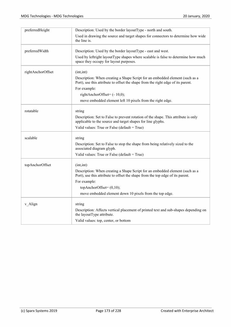
MDG Technologies - MDG Technologies 20 January, 2020
preferredHeight Description: Used by the border layoutType - north and south.
Used in drawing the source and target shapes for connectors to determine how widethe line is.
preferredWidth Description: Used by the border layoutType - east and west.
Used by leftright layoutType shapes where scalable is false to determine how muchspace they occupy for layout purposes.
rightAnchorOffset (int,int)
Description: When creating a Shape Script for an embedded element (such as aPort), use this attribute to offset the shape from the right edge of its parent.
For example:
rightAnchorOffset= (- 10,0);
move embedded element left 10 pixels from the right edge.
rotatable string
Description: Set to False to prevent rotation of the shape. This attribute is onlyapplicable to the source and target shapes for line glyphs.
Valid values: True or False (default = True)
scalable string
Description: Set to False to stop the shape from being relatively sized to theassociated diagram glyph.
Valid values: True or False (default = True)
topAnchorOffset (int,int)
Description: When creating a Shape Script for an embedded element (such as aPort), use this attribute to offset the shape from the top edge of its parent.
For example:
topAnchorOffset= (0,10);
move embedded element down 10 pixels from the top edge.
v_Align string
Description: Affects vertical placement of printed text and sub-shapes depending onthe layoutType attribute.
Valid values: top, center, or bottom
(c) Sparx Systems 2019 Page 173 of 228 Created with Enterprise Architect

MDG Technologies - MDG Technologies 20 January, 2020
Drawing Methods
When you create a shape using a Shape Script, you define the values of the shape using methods. The values includethings such as:
What the shape is - a rectangle, a line, a sphere·
The size of the shape·
The colors of the shape and borders·
The compartments and compartment text the shape has·
The text and labels displayed in and around the shape·
Whether the shape consists of or includes a captured image·
You can list the valid methods (commands) for any point in a script by pressing Ctrl+Space.
Method Syntax
<MethodName> "(" <ParameterList> ")";";
Example
shape main
{
// Initialisation Attributes - these must be before drawing commands
noshadow = "true";
h_align = "center";
//drawing commands (Methods)
rectangle (0,0,100,100);
println ("foo bar");
}
Methods
Method Name Description
addsubshape(stringshapename(int width, intheight))
Adds a sub-shape with the name 'shapename' that must be defined within thecurrent shape definition.
appendcompartmenttext(string)
Appends additional strings to a compartment's text.
The compartment the text is added to depends on the compartment name set using'setcompartmentname' prior to using 'appendcompartmenttext'.
This method must be called to have the compartment displayed.
arc(int left, int top, intright, int bottom, int
Draws an elliptical anticlockwise arc with the ellipse having extents at left, top,right and bottom.
(c) Sparx Systems 2019 Page 174 of 228 Created with Enterprise Architect

MDG Technologies - MDG Technologies 20 January, 2020
startingpointx, intstartingpointy, intendingpointx, intendingpointy)
The start point of the arc is defined by the intersection of the ellipse and the linefrom the center of the ellipse to the point (startingpointx, startingpointy).
The end of the arc is similarly defined by the intersection of the ellipse and the linefrom the center of the ellipse to the point (endingpointx, endingpointy).
For example:
Arc(0, 0, 100, 100, 95, 0, 5, 0);
arcto(int left, int top, intright, int bottom, intstartingpointx, intstartingpointy, intendingpointx, intendingpointy)
As for the arc method, except that a line is drawn from the current position to thestarting point of the arc, and then the current position is updated to the end point ofthe arc.
bezierto(int controlpoint1x,int controlpoint1y, intcontrolpoint2x, intcontrolpoint2y, intendpointx, int endpointy)
Draws a bezier curve and updates the pen position.
defSize(int width, intheight)
Sets the default size of the element.
This can appear in IF and ELSE clauses with different values in each, and causesthe element to be resized automatically each time the values change.
if(HasTag("horizontal","true"))
{
defSize(100,20);
rectangle(0,0,100,100);
}
else
{
defSize(20,100);
rectangle(0,0,100,100);
}
This example sets the shape to the specified default size each time the TaggedValue 'horizontal' is changed.
When this is set, Alt+Z also resizes the shape to the defined dimensions.
The minimum value for both int width and int height is 10.
(c) Sparx Systems 2019 Page 175 of 228 Created with Enterprise Architect
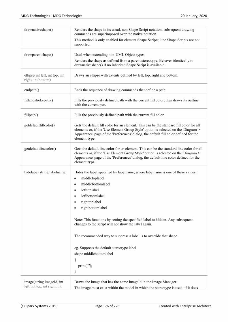
MDG Technologies - MDG Technologies 20 January, 2020
drawnativeshape() Renders the shape in its usual, non Shape Script notation; subsequent drawingcommands are superimposed over the native notation.
This method is only enabled for element Shape Scripts; line Shape Scripts are notsupported.
drawparentshape() Used when extending non-UML Object types.
Renders the shape as defined from a parent stereotype. Behaves identically todrawnativeshape() if no inherited Shape Script is available.
ellipse(int left, int top, intright, int bottom)
Draws an ellipse with extents defined by left, top, right and bottom.
endpath() Ends the sequence of drawing commands that define a path.
fillandstrokepath() Fills the previously defined path with the current fill color, then draws its outlinewith the current pen.
fillpath() Fills the previously defined path with the current fill color.
getdefaultfillcolor() Gets the default fill color for an element. This can be the standard fill color for allelements or, if the 'Use Element Group Style' option is selected on the 'Diagram >Appearance' page of the 'Preferences' dialog, the default fill color defined for theelement type.
getdefaultlinecolor() Gets the default line color for an element. This can be the standard line color for allelements or, if the 'Use Element Group Style' option is selected on the 'Diagram >Appearance' page of the 'Preferences' dialog, the default line color defined for theelement type.
hidelabel(string labelname) Hides the label specified by labelname, where labelname is one of these values:
middletoplabel·
middlebottomlabel·
lefttoplabel·
leftbottomlabel·
righttoplabel·
rightbottomlabel·
Note: This functions by setting the specified label to hidden. Any subsequentchanges to the script will not show the label again.
The recommended way to suppress a label is to override that shape.
eg. Suppress the default stereotype label
shape middlebottomlabel
{
print("");
}
image(string imageId, intleft, int top, int right, int
Draws the image that has the name imageId in the Image Manager.
The image must exist within the model in which the stereotype is used; if it does
(c) Sparx Systems 2019 Page 176 of 228 Created with Enterprise Architect

MDG Technologies - MDG Technologies 20 January, 2020
bottom) not already exist in the model, you must import it as reference data or select it fromwithin a technology file.
If the image is in a technology file, it should have a filename of the format<technology ID>::<imagename>.<extension>.
lineto(int x, int y) Draws a line from the current cursor position to a point specified by x and y, andthen updates the pen cursor to that position. (See the Notes section also.)
moveto(int x, int y) Moves the pen cursor to the point specified by x and y.
polygon(int centerx,intcentery, int numberofsides,int radius, float rotation)
Draws a regular polygon with center at the point (centerx, centery), andnumberofsides number of sides.
print(string text) Prints the specified text string.
You cannot change the font size or type of this text.
printifdefined(stringpropertyname, stringtruepart(, string falsepart))
Prints the 'truepart' if the given property exists and has a non-empty value,otherwise prints the optional 'falsepart'.
You cannot change the font size or type of this text.
println(string text) Appends a line of text to the shape and a line break.
You cannot change the font size or type of this text.
printwrapped(string text) Prints the specified text string, wrapped over multiple lines if the text is wider thanits containing shape.
You cannot change the font size or type of this text.
rectangle(int left, int top,int right, int bottom)
Draws a rectangle with extents at left, top, right, bottom. Values are percentages.
roundrect(int left, int top,int right, int bottom, intabs_cornerwidth, intabs_cornerheight)
Draws a rectangle with rounded corners, with extents defined by left, top, right andbottom.
The size for the corners is defined by abs_cornerwidth and abs_cornerheight; thesevalues do not scale with the shape.
setcompartmentname(string)
Sets a compartment name to the string provided.
This method must be used before calling appendcompartmenttext; calling this aftercalling appendcompartmenttext clears any text that has already been added to thecompartment.
setdefaultcolors() Returns the brush and pen color to the default settings, or to the user-defined colorsif available.
setfillcolor(int red, intgreen, int blue) or
setfillcolor(ColornewColor)
Sets the fill color.
You can specify the required color by defining RGB values or using a color valuereturned by any of the Color Queries such as:
GetUserFillColor() or
GetUserBorderColor()
In all cases setfillcolor takes precedence over any color definition that applies to theelement.
(c) Sparx Systems 2019 Page 177 of 228 Created with Enterprise Architect

MDG Technologies - MDG Technologies 20 January, 2020
setfixedregion(int xStart,int yStart, int xEnd, intyEnd)
Fixes a region in a connector into which a sub-shape can be drawn, so that thesub-shape is not rescaled with the length or orientation of the connector line.
For an example, see the 'Rotation Direction' script in the Example Scripts topic.
setfontcolor(int red, intgreen, int blue) or
setfontcolor(ColornewColor)
Sets the font color of a text string.
You can specify the required color by defining RGB values or using a color valuereturned by any of the Color Queries such as:
GetUserFontColor() or
GetUserFillColor()
You can use this command with any of the text print commands.
setlinestyle(string linestyle) Changes the stroke pattern for commands that use the pen.
string linestyle: has these valid styles:
solid·
dash·
dot·
dashdot·
dashdotdot·
double·
(See the Notes section also.)
setorigin(string relativeTo,int xOffset, int yOffset)
Positions floating text labels relative to the main shape.
relativeTo is one of N, NE, E, SE, S, SW, W, NW, CENTER·
xOffset and yOffset are in pixels, not percentage values, and can be negative·
setpen(int red, int green, intblue, int penwidth) orsetpen(Color newcolor, intpenwidth)
Sets the pen to the defined color and sets the pen width.
This method is only for line-drawing commands. It does not affect any text printcommands.
setpencolor(int red, intgreen, int blue) orsetpencolor(ColornewColor)
Sets the pen color.
You can specify the required color by defining RGB values or using a color valuereturned by any of the Color Queries such as:
GetUserFillColor()
This method is only for line-drawing commands. It does not affect any text printcommands.
setpenwidth(int penwidth) Sets the width of the pen. Pen width should be between 1 and 5.
This method is only for line-drawing commands. It does not affect any text printcommands.
showlabel(stringlabelname)
Reveals the hidden label specified by labelname, where labelname is one of thesevalues:
middletoplabel·
middlebottomlabel·
lefttoplabel·
leftbottomlabel·
righttoplabel·
rightbottomlabel·
(c) Sparx Systems 2019 Page 178 of 228 Created with Enterprise Architect

MDG Technologies - MDG Technologies 20 January, 2020
startcloudpath(puffWidth,puffHeight, noise)
Similar to startpath, except that it draws the path with cloud-like curved segments(puffs).
Parameters:
float puffWidth (default = 30), the horizontal distance between puffs·
float puffHeight (default = 15), the vertical distance between puffs·
float noise (default = 1.0), the randomization of the puffs' positions·
startpath() Starts the sequence of drawing commands that define a path.
strokepath() Draws the outline of the previously defined path with the current pen.
Notes
If you draw a Shape Script for a line consisting of several segments and define different line styles for the segments,·all segments except for the center segment use the first line style defined; the center segment uses the second linestyle defined, as shown:
shape main{
noShadow=true;
// This pen style will be ignored because nothing is drawn.
setpen(0,0,0,1);
SetLineStyle("solid");
// This pen style will be used for non-center segments because it is
// the first that is used for drawing.
setpen(255,0,0,2);
SetLineStyle("dash");
moveto(0,0);
lineto(50,0);
// This line style is used in the center segment, but no others because it
// isn't the first one drawn with.
setpen(0,255,0,1);
SetLineStyle("dot");
lineto(100,0);
// This line style is used for an annotation in the center segment only.
setpen(0,0,0,1);
SetLineStyle("solid");
setfixedregion(40,-10,60,10);
ellipse(40,-10,60,10);
}
(c) Sparx Systems 2019 Page 179 of 228 Created with Enterprise Architect

MDG Technologies - MDG Technologies 20 January, 2020
A Dependency connector with this Shape Script might resemble this:
(c) Sparx Systems 2019 Page 180 of 228 Created with Enterprise Architect

MDG Technologies - MDG Technologies 20 January, 2020
Color Queries
In defining your shape, you might want to retain the fill, border and font colors you have already defined for the baseshape. You can set the color definition using a color query to retrieve arguments for the SetPenColor and SetFillColorcommands. These queries can be used in place of arguments.
getUserFillColor() - returns the user-selected fill color of the current element·
getUserBorderColor() - returns the user-selected border/line color of the current element·
getUserFontColor() - returns the user-selected text font color of the current element·
getUserPenSize() - returns the user-selected line thickness ofthe current element·
getDefaultFillColor() - returns the default fill color for the current element without using the colors applied to this·element
getDefaultLineColor() - returns the default line color for the current element without using the colors applied to this·element
getStatusColor() - returns the status color for the current element; if no color is defined for this status, or status·colors are not displayed against this type, this query will return the same as getUserFillColor
For example:
shape main
{
setfillcolor(getuserfillcolor());
setpencolor(getuserbordercolor());
rectangle(0,0,100,100);
}
Notes
The user colors are those that would be set on the base object if it were not being modified by the Shape Script; they·would have been defined using - in order of decreasing precedence - the Format toolbar options, the 'Appearance'options (F4) or the 'Preferences' dialog ('Start> Desktop > Preferences > Preferences')
Because the user colors are those defined for an element to which the stereotype and Shape Script are subsequently·applied, they cannot be depicted in the 'Preview' panel of the Shape Editor
(c) Sparx Systems 2019 Page 181 of 228 Created with Enterprise Architect

MDG Technologies - MDG Technologies 20 January, 2020
Conditional Branching
You can incorporate condition branching in your Shape Scripts, using either the 'IfElse' statement or query methods thatevaluate to True or False.
When you use these conditional branching statements, you can use the return command to terminate execution of thescript when a branch condition has been satisfied. The Example Scripts topic provides several examples of this, such asthe 'Return Statement Shape' script.
(c) Sparx Systems 2019 Page 182 of 228 Created with Enterprise Architect
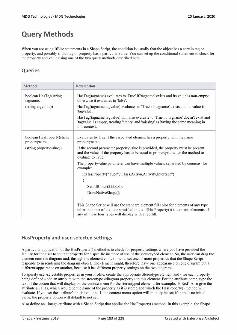
MDG Technologies - MDG Technologies 20 January, 2020
Query Methods
When you are using IfElse statements in a Shape Script, the condition is usually that the object has a certain tag orproperty, and possibly if that tag or property has a particular value. You can set up the conditional statement to check forthe property and value using one of the two query methods described here.
Queries
Method Description
boolean HasTag(stringtagname,
(string tagvalue))
HasTag(tagname) evaluates to 'True' if 'tagname' exists and its value is non-empty;otherwise it evaluates to 'false'.
HasTag(tagname,tagvalue) evaluates to 'True' if 'tagname' exists and its value is'tagvalue'.
HasTag(tagname,tagvalue) will also evaluate to 'True' if 'tagname' doesn't exist and'tagvalue' is empty, treating 'empty' and 'missing' as having the same meaning inthis context.
boolean HasProperty(stringpropertyname,
(string propertyvalue))
Evaluates to True if the associated element has a property with the namepropertyname.
If the second parameter propertyvalue is provided, the property must be present,and the value of the property has to be equal to propertyvalue for the method toevaluate to True.
The propertyvalue parameter can have multiple values, separated by commas; forexample:
if(HasProperty("Type","Class,Action,Activity,Interface"))
{
SetFillColor(255,0,0);
DrawNativeShape();
}
This Shape Script will use the standard element fill color for elements of any typeother than one of the four specified in the if(HasProperty()) statement; elements ofany of those four types will display with a red fill.
HasProperty and user-selected settings
A particular application of the HasProperty() method is to check for property settings where you have provided thefacility for the user to set that property for a specific instance of use of the stereotyped element. So, the user can drag theelement onto the diagram and, through the element context menu, set one or more properties that the Shape Scriptresponds to in rendering the diagram object. The element might, therefore, have one appearance on one diagram but adifferent appearance on another, because it has different property settings on the two diagrams.
To specify user-selectable properties in your Profile, create the appropriate Stereotype element and - for each propertybeing defined - add an attribute with the stereotype «diagram property» to this element. For the attribute name, type thetext of the option that will display on the context menu for the stereotyped element; for example, 'Is Red'. Also give theattribute an alias, which would be the name of the property as it is stored and which the HasProperty() method willevaluate. If you set the attribute's initial value to 1, the context menu option will initially be set; if there is no initialvalue, the property option will default to not set.
Also define an _image attribute with a Shape Script that applies the HasProperty() method. In this example, the Shape
(c) Sparx Systems 2019 Page 183 of 228 Created with Enterprise Architect

MDG Technologies - MDG Technologies 20 January, 2020
Script defines two Class properties (Is Red and Is Triangle) for the HasProperty() method to check whether the option isset or not.
shape main
{
if (HasProperty("IsRed","1"))
{
SetFillColor(255,128,128);
}
if (HasProperty("IsTriangle","0"))
{
Polygon(50,50,3,50,0);
}
else
{
DrawNativeShape();
}
}
When the Stereotype for the extended element type is defined, it will resemble this:
After the MDG Technology is created and released to your users, when they drag the stereotyped element from theToolbox it will be rendered according to current settings for the defined properties, which the users can access and re-setthrough the context menu, as shown:
(c) Sparx Systems 2019 Page 184 of 228 Created with Enterprise Architect

MDG Technologies - MDG Technologies 20 January, 2020
(c) Sparx Systems 2019 Page 185 of 228 Created with Enterprise Architect

MDG Technologies - MDG Technologies 20 January, 2020
Display Element/Connector Properties
A common component of a customized shape is a text string, which can include the name and value of one of theproperties of the element or connector. To display the text, you use one of the commands:
print·
println and·
printwrapped·
These all take a string parameter representing the text to be displayed. The element or connector property can be added tothe text using the substitution macro #<propertyname>#; for example:
println("name: #NAME#");
You can display several properties by issuing the commands several times, once for each property. The element andconnector properties you can display are listed here. Additionally, you can display Tagged Values by prefixing the tagname with TAG, as shown:
print("#TAG:condition#");
You can also test for and display an element's custom properties in the same way as you do the system-named properties;for example:
if(hasproperty("Name","Value"))
...
and:
print("#Name#");
Properties for Element Shape Scripts
actualname - same as 'name' except that it does not react to the 'Use Alias if Available' setting·
addin - returns a value from an invoked Add-In function; syntax:· addin:<addin_name>, <function_name>, <parameter> [, <parameter> ...]Note that in the hasproperty() argument, Enterprise Architect requires the hash characters for addin values: if(hasproperty("#ADDIN:MyAddin,MyValue#", "TheValue")) {
alias·
author·
cardinality·
classifier·
classifier.actualname - same as 'classifier.name' except that it does not react to the 'Use Alias if Available' setting·
classifier.alias·
classifier.metatype·
classifier.name·
classifier.stereotype·
classifier.type·
complexity·
concurrency·
datecreated·
datemodified·
diagram.handdrawn·
diagram.mdgtype·
(c) Sparx Systems 2019 Page 186 of 228 Created with Enterprise Architect

MDG Technologies - MDG Technologies 20 January, 2020
diagram.name·
diagram.stereotype·
diagram.type·
ES (adds the End Stereotype character(s) as determined by the "Use extended << and >> characters" option)·
haslinkeddocument·
incomingedge (returns "none", "left", "right", "top", "bottom", or "multiple")·
isabstract·
isactive·
iscomposite·
isdrawcompositelinkicon·
isembedded·
isinparent·
isleaf·
islocked·
isroot·
isspec·
istagged·
isvisible·
keywords·
language·
metatype·
multiplicity·
name·
notes·
notesvisible·
outgoingedge (returns "none", "left", "right", "top", "bottom", or "multiple")·
packagename·
packagepath·
package.stereotype·
parentedge ("right", "left", "top", "bottom")·
parent.metatype·
partition (returns "vertical" or "horizontal")·
persistence·
phase·
priority·
propertytype·
propertytype.alias·
propertytype.metatype·
propertytype.name·
propertytype.stereotype·
qualifiedname·
rectanglenotation·
(c) Sparx Systems 2019 Page 187 of 228 Created with Enterprise Architect

MDG Technologies - MDG Technologies 20 January, 2020
scope·
showcomposeddiagram (returns "True" or "False")·
SS (adds the Start Stereotype character(s) as determined by the "Use extended << and >> characters" option)·
status·
stereotype·
stereotypehidden·
subtype·
type·
version·
visibility·
Properties for Connector Shape Scripts
actualname - same as 'name' except that it does not react to the 'Use Alias if Available' setting·
addin - returns a value from an invoked Add-In function; syntax:· addin:<addin_name>, <function_name>, <parameter> [, <parameter> ...]Note that in the hasproperty() argument, Enterprise Architect requires the hash characters for addin values: if(hasproperty("#ADDIN:MyAddin,MyValue#", "TheValue")) {
alias·
diagram.connectornotation·
diagram.handdrawn·
diagram.mdgtype·
diagram.name·
diagram.stereotype·
diagram.type·
direction·
effect·
ES - adds the End Stereotype character(s) as determined by the "Use extended << and >> characters" option·
guard·
isroot·
isleaf·
name·
rotationdirection ("up", "down", "left", "right")·
source.actualname - same as 'source.name' except that it does not react to the 'Use Alias if Available' setting·
source.aggregation·
source.alias·
source.changeable·
source.constraints·
source.element.name·
source.element.stereotype·
source.metatype - the target element must match the exact stereotype defined at the source·
source.metatype.general - the target element can match the exact stereotype used at the source and any concrete·(isAbstract=false) generalized stereotypes
(c) Sparx Systems 2019 Page 188 of 228 Created with Enterprise Architect

MDG Technologies - MDG Technologies 20 January, 2020
source.metatype.specific - the target element can match the exact stereotype used at the source and any concrete·(isAbstract=false) specialized stereotypes
source.metatype.both - the target element can match the exact stereotype used at the source and any concrete·(isAbstract=false) generalized or specialized stereotypes
source.multiplicity·
source.multiplicityisordered·
source.name·
source.qualifiers·
source.stereotype·
source.targetscope·
SS - adds the Start Stereotype character(s) as determined by the "Use extended << and >> characters" option·
stereotype·
target.actualname - same as 'target.name' except that it does not react to the 'Use Alias if Available' setting·
target.aggregation·
target.alias·
target.changeable·
target.constraints·
target.element.name·
target.element.stereotype·
target.metatype·
target.multiplicity·
target.multiplicityisordered·
target.name·
target.qualifiers·
target.stereotype·
target.targetscope·
triggers·
type·
weight·
(c) Sparx Systems 2019 Page 189 of 228 Created with Enterprise Architect

MDG Technologies - MDG Technologies 20 January, 2020
Sub-Shapes
When you define an element or connector shape using a Shape Script, you can build the shape from separatecomponents, defined as sub-shapes. Using sub-shapes, you can create complex shapes that more closely resemble theobjects that they represent.
Sub-shape Layout
To set the layout type you use the layoutType attribute, which must be set in the initialization attributes section of thescript; in other words, before any of the methods are called. Valid values for this attribute are:
LeftRight - Shapes with this layout position the sub-shapes side by side, with the first added on the left, and·subsequent sub-shapes to the right
TopDown - Places the sub-shapes in a vertical arrangement, with the first sub-shape added to the top and subsequent·sub-shapes added beneath
Border - This requires an additional argument to the addsubshape method to specify which region of the containing·shape the sub-shape is to occupy: N, E, S, W or CENTER; each region can only be occupied by one sub-shapeA sub-shape that is assigned to the E or W region must have its preferredwidth attribute specified in its declarationand, similarly, sub-shapes added to N or S must have their preferredheight attribute set; in this case, the values forthese attributes are treated as static lengths and do not scale glyphs
Example
shape main
{
layouttype="topdown";
setfillcolor(0,0,255);
rectangle(0,0,100,100);
addsubshape("sub",50,100,20,0);
addsubshape("sub",50,100,30,-100);
addsubshape("sub",50,100,40,-200);
addsubshape("sub",50,100,50,-300);
shape sub
{
setfillcolor(0,255,0);
ellipse(0,0,100,100);
}
}
The script defines this shape:
(c) Sparx Systems 2019 Page 190 of 228 Created with Enterprise Architect

MDG Technologies - MDG Technologies 20 January, 2020
(c) Sparx Systems 2019 Page 191 of 228 Created with Enterprise Architect

MDG Technologies - MDG Technologies 20 January, 2020
Add Custom Compartments to Element
When you display an element on a diagram in normal, rectangular format, it is possible to show a number ofcompartments within that frame to reveal added characteristics such as attributes, operations and Notes, using thediagram 'Properties' and element 'Compartment Visibility' dialogs. If you want to reveal other added characteristics, suchas related elements or Ports and Parts, you can use a Shape Script to add custom compartments to the diagram display ofthe element. You would usually add this Shape Script to a Stereotype element in a Profile.
Having created a custom compartment, you can add a linked Note to the element to display the content of thecompartment, as you can for the other features of the element.
Access
Define a Stereotype element in a Profile, and use the special attribute '_image' to specify a Shape Script that adds customcompartments.
Ribbon Design > Element > Features > Attributes : [create an attribute named '_image'] >
click on the icon in the 'Initial Value' field
Configure > Reference Data > UML Types > Stereotypes : (select or specifystereotype) : Shape Script > Assign
Context Menu In diagram, right-click on element | Features | Attributes : [create an attribute
named '_image'] | click on in the 'Initial Value' field
Keyboard ShortcutsF9 : [create an attribute named '_image'] > click on the icon in the 'InitialValue' field
Add custom compartments to elements
This table provides notes on creating Shape Scripts that define custom compartments, and a variety of examples.
Process Description
Develop script For the selected stereotype, open the Shape Editor.
In the script, replace shape main with:
shape ChildElement or·
shape RelatedElement·
You can keep shape main if you prefer, to adjust some properties of the mainelement (such as color); however, the main shape then requires a call to'DrawNativeShape()' in order to work correctly.
At this point, you can use the 'HasProperty' query method to search child or relatedelements for specific properties (such as stereotypes) to be displayed incompartments. A RelatedElement Shape Script determines properties of elementsthat are linked to the current element via connectors.
Visibility of each individual custom compartment defined by a Shape Script iscontrolled using the 'Compartment Visibility' dialog. ChildElement compartmentsare visible by default and can be hidden using the compartment visibility options,whilst RelatedElement compartments are hidden by default and must be explicitly
(c) Sparx Systems 2019 Page 192 of 228 Created with Enterprise Architect

MDG Technologies - MDG Technologies 20 January, 2020
enabled using the compartment visibility options.
Be aware, also, that child elements can be shown in a custom compartment eitherwhen they are on the diagram with the parent element or when they are not on thediagram (as in examples 1, 2 and 3). Related elements can only be listed in acompartment if they are NOT on the same diagram (as in examples 4 and 5).
Attach Linked Note You can use one of two methods to create a linked Note to display customcompartment contents:
Method 1 (the element is currently displaying custom compartments) -·highlight the related or child element name in the custom compartment, thenright-click on it and select the 'Create Linked Note' option; the customcompartment is automatically closed, and the linked Note added to the diagramlisting all element names in that compartment
Method 2 (the element is not necessarily showing custom compartments) - drag·a Note element from the 'Common' page of the Diagram Toolbox and link it tothe element containing the custom compartment with a Notelink connectorRight-click on the connector and select the 'Link this note to an elementfeature' option, to display the 'Link note to element feature' dialog; click on thedrop-down arrow in the 'Feature Type' field and click on the name of thecustom compartment, such as 'Properties', then click on the OK buttonThe contents of that compartment are displayed in the Note
In Method 2, if the compartment is displayed the method will NOT hide thecompartment. It is recommended that you use this method if the compartment isalready hidden.
Any changes you make to the list of elements in the compartment, or their names,are immediately reflected in the Note to maintain the accuracy of the displayedinformation.
Script Example 1: Addcompartment withoutadjusting the parentelement
//Add compartments for Child elements.
shape ChildElement
{
//Check if a child element has the property stereotype, if so set
//the compartment name to Properties.
if(HasProperty("stereotype", "property"))
{
SetCompartmentName("Properties");
}
//Check if the child element has a public scope and if so add the +
//symbol to the child compartment.
if(HasProperty("scope", "public"))
{
AppendCompartmentText("+");
}
//Add the child elements name to the child compartment.
AppendCompartmentText("#NAME#");
}
The Shape Script checks all child elements to see if they have a stereotype of<<property>>. If this stereotype is found, the 'SetCompartmentName' function setsa compartment called 'Properties'.
The script then checks whether the child element has a 'public' scope and, if it does,
(c) Sparx Systems 2019 Page 193 of 228 Created with Enterprise Architect

MDG Technologies - MDG Technologies 20 January, 2020
appends the '+' symbol.
Finally, the 'AppendCompartmentText' function adds the child element's name tothe compartment.
If a compartment has already been declared by 'SetCompartmentName', anyadditional child elements that fall under the same compartment are automaticallyadded to it without having to declare a new compartment name (that is, all childelements with the stereotype <<property>> end up in the 'Properties' compartment).
Script Example 2: Adjustthe color of the parentelement and add childcompartments
//Shape main affects the parent
shape main
{
//Set the color of the parent element to red
setfillcolor(255,0,0);
//draw the parents native shape
drawnativeshape();
}
//Shape ChildElement adds Child Compartments to the parent.
shape ChildElement
{
if(HasProperty("stereotype", "part"))
{
SetCompartmentName("Parts");
}
else if(HasProperty("stereotype", "mystereotype"))
{
SetCompartmentName("My Stereotype");
}
AppendCompartmentText("#NAME#");
}
The 'shape main' section sets the color of the main element to red and adds childcompartments based upon stereotyped child elements.
The script checks whether a child element has either the stereotype value 'part' or'mystereotype' applied to it. If there are multiple child elements, having acombination of 'part" and 'mystereotype' stereotypes, two compartments are createdcalled 'Parts' and 'My Stereotype'.
In order to display the compartments, 'AppendCompartmentText' must be called toinsert content into the compartment.
Values passed to 'SetCompartmentName' and 'AppendCompartmentText' can notcontain new line characters.
Script Example 3: Only listchild element incompartment if it is notalready visible on thediagram
shape ChildElement
{
//Check if the child element is on the diagram or not.
if(hasproperty("IsVisible", "False"))
{
(c) Sparx Systems 2019 Page 194 of 228 Created with Enterprise Architect

MDG Technologies - MDG Technologies 20 January, 2020
//Create a compartment for parts.
if(hasproperty("type", "part"))
{
SetCompartmentName("Parts");
}
//Create a compartment for ports.
else if(hasproperty("type", "port"))
{
SetCompartmentName("Ports");
}
//Add child element name to compartment.
AppendCompartmentText("#NAME#");
}
}
This script adds custom compartments for Port and Part elements that belong to thecurrent element but that are not visible on the current diagram.
The 'IsVisible' property returns True if the child element is already visible on thediagram, False if the child element is not visible.
This can be used to prevent the child element from being listed in the customcompartment if it is already visible on the diagram, avoiding display of redundantinformation.
Script Example 4: Displayelements that are the targetof a Dependency connectorfrom the element that ownsthe Shape Script
shape RelatedElement
{
//Check if the current connector we are processing has a
//dependency type.
if(HasProperty("Connector.Type", "Dependency"))
{
//Check if the element we are currently checking is
//the target of the current connector.
if(HasProperty("Element.IsTarget"))
{
//Set the compartment Name
SetCompartmentName("dependsOn");
if(HasProperty("Element.Stereotype", ""))
{
}
else
{
AppendCompartmentText("«#Element.Stereotype#»");
}
AppendCompartmentText("#Element.Name#");
}
}
}
(c) Sparx Systems 2019 Page 195 of 228 Created with Enterprise Architect

MDG Technologies - MDG Technologies 20 January, 2020
With this script, if a Class1 has a stereotype with the 'RelatedElement' Shape Scriptand Class1 is the source of a Dependency connector to the target Class2, then thename Class2 is displayed in a compartment of Class 1, called 'dependsOn'.
Script Example 5: Displaya list of Realized Interfaceswithin a compartment onan element
shape RelatedElement
{
//Check if the current connector being processed is a Realization
if(HasProperty("Connector.Type", "Realization"))
{
//Only display this compartment if the related element we
//are checking is the target of the connector that has this
//Shape Script element as the source
if(HasProperty("Element.IsTarget"))
{
//If the element is an interface, display it in
//'realizedInterfaces' compartment
if(HasProperty("Element.Type", "Interface"))
{
SetCompartmentName("realizedInterfaces");
AppendCompartmentText("#Element.Name#");
}
}
}
}
If an element Class 1 has this Shape Script and is the source of a Realizationconnector to an element Interface 1, the name 'Interface 1' is displayed in the'realizedInterfaces' compartment of Class 1.
Notes
If you use punctuation within a compartment name, it is stripped out when the script is saved; for example: 'Ports,·Parts and Properties' becomes 'Ports Parts and Properties'
The 'RelatedElement' Shape Scripts have extended capabilities to check both a connector and the element on the·other end of the connector; they are applied only to an element and are solely used to retrieve information to bedisplayed within a compartment of that element
(c) Sparx Systems 2019 Page 196 of 228 Created with Enterprise Architect

MDG Technologies - MDG Technologies 20 January, 2020
Show Composite Diagram
You can define an element as being Composite (using the 'New Diagram | Composite Structure Diagram' context menuoption), in which case the element has a child Composite diagram depicting the substructure of the element. You can alsouse context menu options to display the Composite diagram on the element, either recasting the element as a frame oradding a compartment to the element. Ordinarily, a Shape Script that redefines the appearance of the Composite elementeffectively circumvents the effect of these options, but you can edit the script to respond to the 'Show CompositeDiagram in Compartment' option and show the child Composite diagram in the center compartment of the element.
To show Composite diagrams, the script requires a layout type of 'border', with the Composite diagram added to thecenter sub-shape of the main shape when drawing. The defining Shape Script statements are, therefore:
shape main
{
layouttype="Border";
if(HasProperty("ShowComposedDiagram", "true"))
{
addsubshape("ComposedDiagram", "CENTER");
}
shape ComposedDiagram
{
DrawComposedDiagram();
}
}
Examples
An example of a Shape Script including a composed diagram is:
Shape main
{
//Set the border type
layouttype="Border";
//Set a cream fill color
setfillcolor(255, 255, 200);
//Draw a base rectangle for the object.
rectangle(0, 0, 100, 100);
//Add some padding to the top of the shape
addsubshape("Padding", "N");
//Check the setting of the context menu option
if(HasProperty("ShowComposedDiagram", "true"))
{
//Add the composed diagram to the center of the object
addsubshape("ComposedDiagram", "CENTER");
(c) Sparx Systems 2019 Page 197 of 228 Created with Enterprise Architect

MDG Technologies - MDG Technologies 20 January, 2020
}
//Add some padding to the bottom of the shape.
addsubshape("Padding", "S");
shape Padding
{
//Set the height of this element
preferredHeight = 20;
//Set the fill color to gray
setfillcolor(128, 128, 128);
//Draw a rectangle that will take up the width of the object and
//have a height of 20 pixels.
rectangle(0, 0, 100, 100);
}
shape ComposedDiagram
{
//Draw the composed diagram.
DrawComposedDiagram();
}
}
This script generates the shape:
Composed diagrams are currently only supported as the center sub-shape of the main shape. Adding the diagram to anyother location will cause the composed diagram to either not draw correctly or not draw at all. The diagram can be asub-shape of a sub-shape, but only if the parent shape and sub-shape(s) all have a "CENTER" orientation. For example:
//This shapescript is fine, because shape E is the center of shape C, which is the center of shape D; that is, all shapesleading to //DrawComposedDiagram are "CENTER".
shape main
{
layouttype = "Border";
(c) Sparx Systems 2019 Page 198 of 228 Created with Enterprise Architect

MDG Technologies - MDG Technologies 20 January, 2020
rectangle (0, 0, 100, 100);
addsubshape ("D", "CENTER");
shape D
{
layouttype= "Border";
addsubshape ("C", "CENTER");
shape C
{
layouttype= "Border";
addsubshape ("E", "CENTER");
addsubshape ("Padding", "N");
addsubshape ("Padding", "S");
shape E
{
DrawComposedDiagram ();
}
shape padding
{
preferredHeight = 20;
setfillcolor (10, 30, 80);
rectangle (0, 0, 100, 100);
}
}
}
}
//This shapescript is not good - shape E is "CENTER", shape C is "S" and shape D is "CENTER"; because shape C isoriented "S"
//the diagram will not draw.
shape main
{
layouttype = "Border";
rectangle (0, 0, 100, 100);
addsubshape ("D", "CENTER");
shape D
{
layouttype= "Border";
addsubshape ("C", "S"); //<- this is bad, all parent subshapes of a DrawComposedDiagram call MUST be
// "CENTER" oriented
shape C
{
(c) Sparx Systems 2019 Page 199 of 228 Created with Enterprise Architect

MDG Technologies - MDG Technologies 20 January, 2020
layouttype= "Border";
addsubshape ("E", "CENTER");
addsubshape ("Padding", "N");
addsubshape ("Padding", "S");
shape E
{
DrawComposedDiagram ();
}
shape padding
{
preferredHeight = 20;
setfillcolor (10, 30, 80);
rectangle (0, 0, 100, 100);
}
}
}
}
Notes
To display the Composite diagram, the 'New Diagram | Show Composite Diagram in Compartment' option should be·selected on the element's context menu in the diagram
The composed diagram is displayed at natural size, so the parent element can not be resized to be smaller than the·composed diagram
(c) Sparx Systems 2019 Page 200 of 228 Created with Enterprise Architect
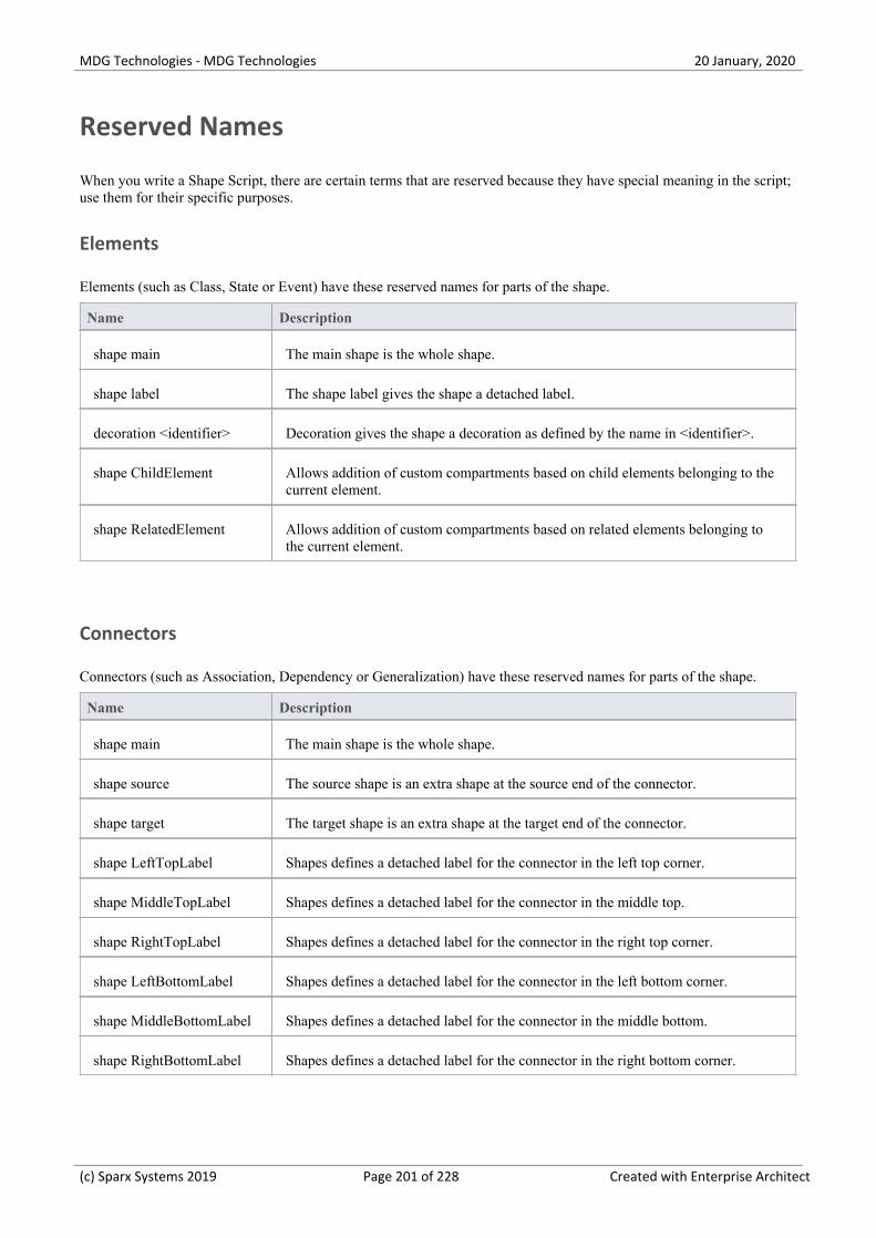
MDG Technologies - MDG Technologies 20 January, 2020
Reserved Names
When you write a Shape Script, there are certain terms that are reserved because they have special meaning in the script;use them for their specific purposes.
Elements
Elements (such as Class, State or Event) have these reserved names for parts of the shape.
Name Description
shape main The main shape is the whole shape.
shape label The shape label gives the shape a detached label.
decoration <identifier> Decoration gives the shape a decoration as defined by the name in <identifier>.
shape ChildElement Allows addition of custom compartments based on child elements belonging to thecurrent element.
shape RelatedElement Allows addition of custom compartments based on related elements belonging tothe current element.
Connectors
Connectors (such as Association, Dependency or Generalization) have these reserved names for parts of the shape.
Name Description
shape main The main shape is the whole shape.
shape source The source shape is an extra shape at the source end of the connector.
shape target The target shape is an extra shape at the target end of the connector.
shape LeftTopLabel Shapes defines a detached label for the connector in the left top corner.
shape MiddleTopLabel Shapes defines a detached label for the connector in the middle top.
shape RightTopLabel Shapes defines a detached label for the connector in the right top corner.
shape LeftBottomLabel Shapes defines a detached label for the connector in the left bottom corner.
shape MiddleBottomLabel Shapes defines a detached label for the connector in the middle bottom.
shape RightBottomLabel Shapes defines a detached label for the connector in the right bottom corner.
(c) Sparx Systems 2019 Page 201 of 228 Created with Enterprise Architect

MDG Technologies - MDG Technologies 20 January, 2020
(c) Sparx Systems 2019 Page 202 of 228 Created with Enterprise Architect

MDG Technologies - MDG Technologies 20 January, 2020
Syntax Grammar
A section of a Shape Script can be quite complex, containing a number of commands and parameters. This table providesa breakdown of the Shape Script structure, illustrating how commands and parameters are constructed. The first entry isthe top-level declaration, and subsequent entries show the composition of successively more detailed components.
Grammar Symbols
* = zero or more·
+ = one or more·
| = or·
; = terminator·
Symbol Description
ShapeScript ::= <Shape>*;
Shape ::= <ShapeDeclaration> <ShapeBody>;
ShapeDeclaration ::= <ShapeType> <ShapeName>;
ShapeType ::= "shape" | "decoration" | "label";
ShapeName ::= <ReservedShapeName> | <stringliteral>;
ReservedShapeName ::= See Reserved Names for full reserved shape listing.
ShapeBody ::= "{" <InitialisationAttributeAssignment>* <DrawingStatement>* <SubShape>*"}";
InitialisationAttributeAssignment ::=
<Attribute> "=" <Value> ";";
Attribute ::= See Shape Attributes for full listing of attribute names.
DrawingStatement ::= <IfElseSection> | <Method>;
IfElseSection ::= "if" "("<QueryExpression>")" <TrueSection> (<ElseSection>);
QueryExpression ::= <QueryName> "(" <ParameterList> ")";
See Query Methods for descriptions of the queries and their parameters.
QueryName ::= See Query Methods for the possible Query names.
TrueSection ::= "{" <DrawingStatement>* "}"
ElseSection ::= "else" "{" <DrawingStatement>* "}"
Method ::= <MethodName> "(" <ParameterList> ")" ";";
(c) Sparx Systems 2019 Page 203 of 228 Created with Enterprise Architect
MDG Technologies - MDG Technologies 20 January, 2020
MethodName ::= See Drawing Methods for a full listing of method names.
(c) Sparx Systems 2019 Page 204 of 228 Created with Enterprise Architect

MDG Technologies - MDG Technologies 20 January, 2020
Example Scripts
You can create a wide range of shapes, effects and text statements using Shape Scripts, to enhance the appearance andinformation value of the elements and connectors you create. Some examples of such scripts are provided here.
Access
Ribbon Configure > Reference Data > UML Types > Stereotypes (specify stereotype) :Shape Script + Assign, or
Configure > Reference Data > UML Types > Stereotypes (specify stereotype) :Shape Script + Edit
Examples
Shape Script
// BASIC SHAPES
shape main
{
setfillcolor(255, 0, 0); // (R,G,B)
rectangle(0, 0, 90, 30); // (x1,y1,x2,y2)
setfillcolor(0, 255, 0); // (R,G,B)
ellipse(0, 30, 90, 60); // (x1,y1,x2,y2)
setfillcolor(0, 0, 255); // (R,G,B)
rectangle(0, 60, 90, 90); // (x1,y1,x2,y2)
}
// SINGLE CONDITIONAL SHAPE
shape main
{
if (HasTag ("Trigger", "Link"))
{
// Only draw if the object has a Tagged Value Trigger=Link
// Set the fill color for the path
setfillcolor(0, 0, 0);
startpath(); // Start to trace out a path
moveto(23, 40);
lineto(23, 60);
lineto(50, 60);
lineto(50, 76);
(c) Sparx Systems 2019 Page 205 of 228 Created with Enterprise Architect

MDG Technologies - MDG Technologies 20 January, 2020
lineto(76, 50);
lineto(50, 23);
lineto(50, 40);
endpath(); // End tracing out a path
// Fill the traced path with the fill color
fillandstrokepath();
return;
}
}
// MULTI CONDITIONAL SHAPE
shape main
{
startpath();
ellipse(0, 0, 100, 100);
endpath();
fillandstrokepath();
ellipse(3, 3, 97,97);
if (HasTag ("Trigger", "None"))
{
return;
}
if (HasTag ("Trigger", "Error"))
{
setfillcolor(0, 0, 0);
startpath();
moveto(23, 77);
lineto(37, 40);
lineto(60, 47);
lineto(77, 23);
lineto(63, 60);
lineto(40, 53);
lineto(23, 77);
endpath();
fillandstrokepath();
return;
}
if (HasTag ("Trigger", "Message"))
{
rectangle(22, 22, 78, 78);
moveto(22, 22);
lineto(50, 50);
lineto(78, 22);
(c) Sparx Systems 2019 Page 206 of 228 Created with Enterprise Architect

MDG Technologies - MDG Technologies 20 January, 2020
return;
}
}
// SUB SHAPES
shape main
{
rectangle(0, 0, 100, 100);
addsubshape("red", 10, 20);
addsubshape("blue", 30, 40);
addsubshape("green", 50, 20);
addsubshape("red", 100, 20);
shape red
{
setfillcolor(200, 50, 100);
rectangle(0, 0, 100, 100);
}
shape blue
{
setfillcolor(100, 50, 200);
rectangle(0, 0, 100, 100);
}
shape green
{
setfillcolor(50, 200, 100);
rectangle(0, 0, 100, 100);
}
}
// EDITABLE FIELD SHAPE
shape main
{
rectangle(0, 0, 100, 100);
addsubshape("namecompartment", 100, 20);
addsubshape("stereotypecompartment", 100, 40);
shape namecompartment
{
h_align = "center";
editablefield = "name";
rectangle(0, 0, 100, 100);
(c) Sparx Systems 2019 Page 207 of 228 Created with Enterprise Architect

MDG Technologies - MDG Technologies 20 January, 2020
println("name: #name#");
}
shape stereotypecompartment
{
h_align = "center";
editablefield = "stereotype";
rectangle(0, 0, 100, 100);
println("stereotype: #stereotype#");
}
}
// RETURN STATEMENT SHAPE
shape main
{
if (hasTag("alternatenotation", "false"))
{
//draw ea's inbuilt glyph
drawnativeshape();
//exit script with the return statement
return;
}
else
{
//alternate notation commands
//...
rectangle(0, 0, 100, 100);
}
}
//EMBEDDED ELEMENT SHAPE POSITION ON PARENT EDGE
shape main
{
defsize(60,60);
startpath();
if(hasproperty("parentedge","top"))
{
moveto(0,100);
lineto(50,0);
lineto(100,100);
}
if(hasproperty("parentedge","bottom"))
{
moveto(0,0);
lineto(50,100);
(c) Sparx Systems 2019 Page 208 of 228 Created with Enterprise Architect

MDG Technologies - MDG Technologies 20 January, 2020
lineto(100,0);
}
if(hasproperty("parentedge","left"))
{
moveto(100,0);
lineto(0,50);
lineto(100,100);
}
if(hasproperty("parentedge","right"))
{
moveto(0,0);
lineto(100,50);
lineto(0,100);
}
endpath();
setfillcolor(153,204,255);
fillandstrokepath();
}
// CLOUD PATH EXAMPLE SHAPE
shape main
{
StartCloudPath();
Rectangle(0, 0, 100, 100);
EndPath();
FillAndStrokePath();
}
// CONNECTOR SHAPE
shape main
{
// draw a dashed line
noshadow=true;
setlinestyle("DASH");
moveto(0,0);
lineto(100,0);
}
shape source
{
// draw a circle at the source end
rotatable = true;
startpath();
ellipse(0,6,12,-6);
endpath();
(c) Sparx Systems 2019 Page 209 of 228 Created with Enterprise Architect

MDG Technologies - MDG Technologies 20 January, 2020
fillandstrokepath();
}
shape target
{
// draw an arrowhead at the target end
rotatable = true;
startpath();
moveto(0,0);
lineto(16,6);
lineto(16,-6);
endpath();
fillandstrokepath();
}
// DOUBLE LINE
shape main
{
setlinestyle("DOUBLE");
moveto(0,0);
lineto(100,0);
}
// ROTATION DIRECTION
shape main
{
moveto(0,0);
lineto(100,0);
setfixedregion(40,-10,60,10);
rectangle(40,-10,60,10);
if(hasproperty("rotationdirection","up"))
{
moveto(60,-10);
lineto(50,0);
lineto(60,10);
}
if(hasproperty("rotationdirection","down"))
{
moveto(40,-10);
lineto(50,0);
lineto(40,10);
}
if(hasproperty("rotationdirection","left"))
{
moveto(40,-10);
(c) Sparx Systems 2019 Page 210 of 228 Created with Enterprise Architect

MDG Technologies - MDG Technologies 20 January, 2020
lineto(50,0);
lineto(60,-10);
}
if(hasproperty("rotationdirection","right"))
{
moveto(40,10);
lineto(50,0);
lineto(60,10);
}
}
// GET A VALUE RETURNED BY AN ADD-IN
shape main
{
//Draw a simple rectangle
Rectangle(0,0,100,100);
//Print string value returned from Add-In "MyAddin",
//Function "MyExample" with two string parameters
Print("#ADDIN:MyAddin, MyExample, param1, param2#");
}
// METHOD SIGNATURE FOR ADD-IN FUNCTION:
// Public Function MyExample(Repository As EA.Repository,
// eaGuid As String, args As Variant) As Variant
// ADD CUSTOM COMPARTMENTS BASED UPON CHILD ELEMENTS
// OR RELATED ELEMENTS
(See the Add Custom Compartments to Element Help topic)
// RETURN THE INCOMING AND OUTGOING EDGE FOR CONNECTORS
// GOING INTO AND OUT OF AN OBJECT
shape main
{
//Draw a simple rectangle
Rectangle(0,0,100,100);
//Print incoming edges on the element
Print("Incoming Edge: #incomingedge#\n");
(c) Sparx Systems 2019 Page 211 of 228 Created with Enterprise Architect

MDG Technologies - MDG Technologies 20 January, 2020
//Print outgoing edges on the element
Print("Outgoing Edge: #outgoingedge#\n");
}
// DRAW A DECORATION ICON ON TOP OF THE DEFAULT
// ELEMENT SHAPE
decoration mail
{
orientation= "NE";
image ("icon image", 0, 0, 100, 100);
// "icon image" being the name of the 16x16 image which is loaded into theImage Manager
}
// DRAW AN IMAGE FROM A FILE, AND AN EDITABLE NAME FIELD
shape main
{
addsubshape ("theimage", 100, 100);
addsubshape ("namecompartment", 100, 100);
shape theimage
{
image ("element image", 0, 0, 100, 100);
// "element image" being the name of the image that is loaded into theImage Manager
}
shape namecompartment
{
h_align = "center";
editablefield = "name";
println ("#name#");
}
}
// CHECK WHETHER A COMPOSITE ELEMENT ICON IS REQUIRED
// AND, IF SO, DRAW ONE
decoration comp
(c) Sparx Systems 2019 Page 212 of 228 Created with Enterprise Architect

MDG Technologies - MDG Technologies 20 January, 2020
{
orientation="SE";
if(hasproperty("IsDrawCompositeLinkIcon","true"))
{
startpath();
ellipse(-80,29,-10,71);
ellipse(10,29,80,71);
moveto(-10,50);
lineto(10,50);
endpath();
strokepath();
}
}
// ALLOW A SHAPESCRIPT TO SHOW THE FULLY SCOPED OBJECT
// NAME OF AN OWNED ELEMENT, INCLUDING OWNING ELEMENTS
// AND OWNING PACKAGES, WHEN THE DIAGRAM PROPERTIES
// 'DISABLE FULLY SCOPED OBJECT NAMES' OPTION IS
// DESELECTED, JUST AS FOR AN ELEMENT WITHOUT A
// SHAPESCRIPT.
shape main
{
layouttype= "border";
rectangle (0, 0, 100, 100);
addsubshape ("padding", "N");
addsubshape ("name", "CENTER");
shape padding
{
preferredheight=8;
}
shape name
{
v_align= "top";
h_align= "center";
printwrapped ("#qualifiedname#");
}
}
// SHOW THE NAME OF THE OWNING PACKAGE WHEN THE ELEMENT
// IS USED ON A DIAGRAM NOT IN THAT PACKAGE, AND THE
// DIAGRAM PROPERTIES 'SHOW NAMESPACE' OPTION IS SELECTED.
shape main
{
layouttype= "border";
v_align= "CENTER";
(c) Sparx Systems 2019 Page 213 of 228 Created with Enterprise Architect

MDG Technologies - MDG Technologies 20 January, 2020
h_align= "CENTER";
ellipse (0, 0, 100, 100);
printwrapped ("#name#");
addsubshape ("path", "S");
shape path
{
v_align= "top";
h_align= "center";
if (hasproperty ("packagepath", ""))
{
}
else
{
printwrapped ("(from #packagepath#)");
}
}
}
(c) Sparx Systems 2019 Page 214 of 228 Created with Enterprise Architect

MDG Technologies - MDG Technologies 20 January, 2020
Tagged Value Types
When you are working with Tagged Values, you can create your own, custom, Tagged Values based on predefined,system-provided Tagged Value Types. With these, you can create:
Tagged Values that are complex and based on predefined types, with or without tag filters·
Structured Tagged Values that are composite, containing other Tagged Values·
Tagged Values that return values from the various reference data tables·
Masked Tagged Values that insert user-provided data into a text string such as line of prompts or field names·
By adding Tagged Values of any type to a Stereotype element in a Profile, you can define additional meta-informationfor the way in which a modeling element appears and behaves in a Technology. The Tagged Values are identified byattributes of the Stereotype element.
Notes
You can transport Tagged Value Type definitions between models, using the 'Configure > Model > Transfer >·Export Reference Data' and 'Import Reference Data' ribbon options; Tagged Value Types are exported as PropertyTypes
(c) Sparx Systems 2019 Page 215 of 228 Created with Enterprise Architect

MDG Technologies - MDG Technologies 20 January, 2020
Create Tagged Value Type from Predefined Types
When you are working with Tagged Values, you might want to use structured Tagged Values; that is, Tagged Values thatcapture and present more complex information in a specific format. The base types for such Tagged Values (the type youcall in when you create a tag in the Tags page of the Properties window) can be easily created specifically for yourmodel, as you can base the customized structured Tagged Value types on a range of predefined Tagged Value types andfilters.
Access
Ribbon Configure > Reference Data > UML Types > Tagged Value Types
Create a custom Structured Tagged Value type
Field/Button Description
Tag Name Type an appropriate name for your new Tagged Value type.
Description Optionally, type a short description or the purpose of the Tagged Value type.
Detail Either copy-and-paste or type the syntax of the predefined structured Tagged ValueType on which to base your new Tagged Value type.
Save Click on this button to save the new structured Tagged Value type.
The Tagged Value type displays in the Defined Tag Types list.
New Optionally, click on this button to clear the fields so that you can enter informationfor another new Tagged Value type.
(c) Sparx Systems 2019 Page 216 of 228 Created with Enterprise Architect

MDG Technologies - MDG Technologies 20 January, 2020
Predefined Structured Types
Tagged Values define a wide range of properties and characteristics of a model element, and some of these propertieshave complex values. For example, you might want your user to select a value between upper and lower limits (using'Spin' arrows), set a date, select a color from a palette, or work through a checklist.
You create these complex Tagged Values from any of a number of predefined Tagged Value types and filters, some ofwhich you might have created yourself (Configure > Reference Data > UML Types > Tagged Value Types).
Tagged Value Type Formats
For each Tagged Value Type, the description includes the syntax for creating the initial values for use of the TaggedValue. The name and format are case-sensitive.
Tagged Value Type Format
AddinBroadcast Type=AddinBroadcast;
Values=YourAddinName;
Used to: Allow an Add-In to respond to an attempt to edit this Tagged Value byshowing a dialog in which the value and notes can be edited.
Boolean Type=Boolean;
Default=Val;
Used to: Provide for the input of True or False, either of which can be the defaultvalue.
CheckList Type=CheckList;
Values=Val1,Val2,Val3;
Used to: Create a checklist of things to be completed or satisfied before an action isapproved or performed.
Val1, Val2, Val3 and so on specify the checklist items, each of which is renderedvia the 'Tags' tab of the Properties window with a checkbox; the tag has the value'Incomplete' until each checkbox is selected, at which point the value is 'Complete'.
For example:
Type=CheckList;
Values=Does the change solve the task\issue given,Does the code have sufficienterror handling,Does the code make sense,Does the code comply with the codingconventions;
Whilst the element Tagged Value compartment and the 'Tags' tab window fieldsdisplay the values 'Complete' or 'Incomplete', document and web reports will showthe list of checklist items and the status of each (True for selected, False forunselected).
Classifier Type=Classifier;
Values=Type1,Type2;
Stereotypes=Stereotype1;
Used to: Deprecated - use RefGUID and RefGUIDList
Color Type=Color;
Default=Val;
Used to: Input a color value from a color chooser menu, where the value is the
(c) Sparx Systems 2019 Page 217 of 228 Created with Enterprise Architect

MDG Technologies - MDG Technologies 20 January, 2020
color's Hex RGB value.
For example, the Hex RGB for Blue is 0000FF, whilst the Hex RGB for Green is00FF00.
Const Type=Const;
Default=Val;
Used to: Create a read-only constant value.
Custom Type=Custom;
Used to: Create your own template for predefined types, using a masked value.
Date Type=Date;
Used to: Input the date for the Tagged Value, from a calendar menu.
DateTime Type=DateTime;
Used to: Deprecated - Use Date
Input the date for the Tagged Value, from a calendar menu.
DiagramRef Type=DiagramRef
Used to: Reference a diagram in the model.
Directory Type=Directory;
Default=Val;
Used to: Enter a directory path from a browser.
You can set a default directory path as a string value.
Enum Type=Enum;
Values=Val1,Val2,Val3;
Default=Val2;
Used to: Define a comma-separated list, where Val1, Val2 and Val3 representvalues in the list and Default represents the default value of the list.
File Type=File;
Default=Val;
Used to: Input a filename from a file browser dialog. The named file can belaunched in its default application.
You can set a default file as a string containing the file path and file name.
Float, Decimal, Double Type=Float;
Type=Decimal;
Type=Double;
Default=Val;
Used to: Enter a Float, Decimal or Double value. These types all map to the sametype of data.
You can set a default for any or all of these.
ImageRef Type=ImageRef;
Used to: Provide a link to an image file held in the Image Manager.
(c) Sparx Systems 2019 Page 218 of 228 Created with Enterprise Architect

MDG Technologies - MDG Technologies 20 January, 2020
Integer Type=Integer;
Default=Val;
Used to: Enter an Integer value, and a default.
Memo Type=Memo;
Used to: Input large and complex values for a tag.
ProgressBar Type=ProgressBar;
Compartment=<Name>; - sets the name of the compartment in which to display theprogress bar; more than one Tagged Value can add a progress bar to onecompartment
Text=<Text>; - displays <text> to the right of the progress bar; to display the valueof the tag with the text, use #VALUE#, for example $#VALUE# or #VALUE#%
MinVal=n; - sets the minimum value that can be shown in the progress bar (must bean integer)
MaxVal=n; - sets the maximum value that can be shown in the progress bar (mustbe an integer)
Used to: Display a progress bar in a compartment of an element, when that elementis shown on a diagram and the Tags compartment is enabled on the 'Elements' pageof the diagram 'Properties' dialog. The tag name displays above the progress bar, asits label.
If neither MinVal or MaxVal are set, the progress bar has default values of 0·and 100
If MinVal is set but MaxVal is not, the maximum value defaults to·MinVal+100
If MaxVal is set but MinVal is not, the minimum value defaults to 0·
If both MinVal and MaxVal are set, MinVal must be lower than MaxVal·
Examples:
Compartment=Current Progress;
Type=ProgressBar;
Text=#VALUE#%;
when used in a tag called Progress withvalue set to 65.
Type=ProgressBar;
MinVal=1000;
MaxVal=100000;
Text=$ #VALUE#;
when used in a tag called Progress withvalue set to 4530.
An element with multiple progress bars.
(c) Sparx Systems 2019 Page 219 of 228 Created with Enterprise Architect

MDG Technologies - MDG Technologies 20 January, 2020
RefGUID Type=RefGUID;
Values=Type1,Type2;
Stereotypes=Stereotype1;
Or
Type=RefGUID;
Metatype=Type;
Used to: Reference an element from the model by specifying the element's GUID,where:
Type1 and Type2 specify one or more allowed diagram objects (such as Class,·Component, attribute or operation)
Stereotype1 represents an allowed stereotype·
Metatype can be used to reference Classifiers or Property types:
Metatype=Classifier; presents all Enterprise Architect-defined Classifier types·to select from
Metatype=Property; presents all Ports, Parts and attributes to select from·
You can set the classifier, attribute or operation for a Tagged Value of this type by
clicking on the button against the Tagged Value in the Properties window.
You can also right-click on the RefGUID Tagged Value name in the Propertieswindow and select the 'Find in Project Browser' option to locate a referenced objectin the Browser window.
RefGUIDList Type=RefGUIDList;
Values=Type1,Type2;
Stereotypes=Stereotype1;
OR
Type=RefGUIDList;
Metatype=Type;
Used to: Reference a list of elements from the model by specifying each element'sGUID, where:
Type1 and Type2 specify one or more allowed diagram objects (such as Class·
(c) Sparx Systems 2019 Page 220 of 228 Created with Enterprise Architect

MDG Technologies - MDG Technologies 20 January, 2020
or Component)
Stereotype1 represents an allowed stereotype·
Metatype can be used to reference Classifiers or Property types:
Metatype=Classifier; presents all Enterprise Architect-defined Classifier types·to select from
Metatype=Property; presents all Ports, Parts and Attributes to select from·
You set the classifier, attribute or operation for a Tagged Value of this type by
clicking on the button against the Tagged Value in the 'Tags' tab of theProperties window.
Spin Type=Spin;
LowerBound=x;
UpperBound=x;
Default=Val;
Used to: Create a spin control with the value of LowerBound being the lowest valueand UpperBound being the highest value.
You can also set a default within that range.
String Type=String;
Default=Val;
Used to: Enter a string value, up to 255 characters in length, and a default textstring.
For longer texts, use Type=Memo.
Time Type=Time;
Used to: Input the time for the Tagged Value.
Timestamp Type=Timestamp;
Used to: Input the date and time for the Tagged Value, from a calendar menu.
URL Type=URL;
Default=Val;
Used to: Enter a web URL. The URL should start with:
'http://'·
'https://' or·
'www.'·
You can set a default URL as a string value.
Tag Filters
You can use filters to restrict where a Tagged Value can be applied.
Filter Format
AppliesTo AppliesTo=Type1,Type2;
Description: Restricts the element types this tag can be applied to, where Type1 and
(c) Sparx Systems 2019 Page 221 of 228 Created with Enterprise Architect

MDG Technologies - MDG Technologies 20 January, 2020
Type2 are the valid types.
Possible values are:
All element types·
All connector types·
Attribute·
Operation, and·
OperationParameter·
BaseStereotype BaseStereotype=S1,S2;
Description: Restricts the stereotypes that this tag belongs to, where S1 and S2 arethe allowed stereotypes.
(c) Sparx Systems 2019 Page 222 of 228 Created with Enterprise Architect

MDG Technologies - MDG Technologies 20 January, 2020
Create Custom Masked Tagged Value Type
If you are creating a custom predefined Tagged Value type, you can achieve great flexibility in designing modelcomponents to accept data entries, by defining a mask that formats the data into a template.
Access
Ribbon Configure > Reference Data > UML Types > Tagged Value Types
Create a masked Tagged Value Type
Field Action
Tag Name Type an appropriate name for the masked Tagged Value Type.
Description Optionally, type a description or the purpose of the Tagged Value Type.
Detail Type or copy-and-paste the Tagged Value structure:
Type=Custom;
Mask=<mask values>;
Template=<template text>;
The mask values are explained in the next table, with an example to demonstratehow to use the template.
The template text defines information to be displayed in every use of this customTagged Value, such as field names and prompts for data.
Save Click on this button to save the new masked Tagged Value type.
The Tagged Value type displays in the Defined Tag Types list.
New Optionally, click on this button to clear the fields so that you can enter informationfor another new Tagged Value type.
Mask Values
When defining the format of the mask in a masked Tagged Value type, use these characters:
Mask Action
D Display a digit only in this character space.
d Display a digit or space only in this character space.
+ Display +, - or a space in this character space.
(c) Sparx Systems 2019 Page 223 of 228 Created with Enterprise Architect

MDG Technologies - MDG Technologies 20 January, 2020
C Display a letter of the alphabet only in this character space.
c Display a letter of the alphabet or a space only in this character space.
A Display any alphanumeric character in this character space.
a Display any alphanumeric character or a space in this character space.
. or <space> Leave a character space, to be filled by text from the Template parameter. Usingdots might make it easier to see how many spaces you have set.
Example
In the diagram, the Mask parameter first defines seven blank spaces, which are occupied by characters defined by theTemplate parameter.
The first two visible characters in the Mask are each represented by a lower case c, indicating that the user can enterinformation as either an alphabetic character or a space.
The next six blank spaces again indicate characters defined by the Template, followed by five characters eachrepresented by a d, which indicates that the user can input data in the form of digits or spaces. The dot marks a space tobe filled by a hyphen from the Template, followed by four more ds (digits or spaces).
The Template syntax defines the template for the Mask parameter, filling in the blank spaces in the Mask. The text is theinformation to be printed with every use of this Tagged Value; the underscored values indicate the character spaces thatare to be occupied by data input by the user, as defined in the 'Mask' option.
(c) Sparx Systems 2019 Page 224 of 228 Created with Enterprise Architect

MDG Technologies - MDG Technologies 20 January, 2020
Create Reference Data Tagged Values
When working with Tagged Values, you might want to use a Reference Data Tagged Value, which is used to return thevalues held in an Enterprise Architect reference table. The base types for such Tagged Values (the type you call in whenyou create a tag in the Tags page of the Properties window) can be easily created specifically for your model, as you canbase the customized Reference Data Tagged Value types on a range of predefined Tagged Value types and filters.
Access
Ribbon Configure > Reference Data > UML Types > Tagged Value Types
Create a custom Reference Data Tagged Value type
Field/Button Description
Tag Name Type an appropriate name for the new Tagged Value type.
Description Optionally, type the a description or the purpose of the Tagged Value type.
Detail Either copy-and-paste or type the syntax of the predefined Reference Data TaggedValue type on which to base your new Tagged Value type.
Save Click on this button to save the new Reference Data Tagged Value type.
The Tagged Value type displays in the Defined Tag Types list.
New Optionally, click on this button to clear the fields so that you can enter informationfor another new Tagged Value type.
Notes
If the values in the reference data are changed after the Tagged Value Type is created, you must reload the system in·order to reflect the changes in the Tagged Value Type
(c) Sparx Systems 2019 Page 225 of 228 Created with Enterprise Architect
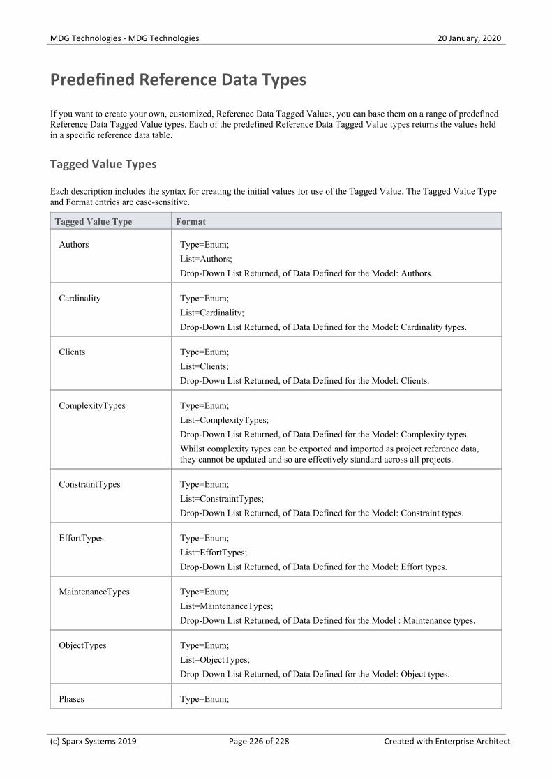
MDG Technologies - MDG Technologies 20 January, 2020
Predefined Reference Data Types
If you want to create your own, customized, Reference Data Tagged Values, you can base them on a range of predefinedReference Data Tagged Value types. Each of the predefined Reference Data Tagged Value types returns the values heldin a specific reference data table.
Tagged Value Types
Each description includes the syntax for creating the initial values for use of the Tagged Value. The Tagged Value Typeand Format entries are case-sensitive.
Tagged Value Type Format
Authors Type=Enum;
List=Authors;
Drop-Down List Returned, of Data Defined for the Model: Authors.
Cardinality Type=Enum;
List=Cardinality;
Drop-Down List Returned, of Data Defined for the Model: Cardinality types.
Clients Type=Enum;
List=Clients;
Drop-Down List Returned, of Data Defined for the Model: Clients.
ComplexityTypes Type=Enum;
List=ComplexityTypes;
Drop-Down List Returned, of Data Defined for the Model: Complexity types.
Whilst complexity types can be exported and imported as project reference data,they cannot be updated and so are effectively standard across all projects.
ConstraintTypes Type=Enum;
List=ConstraintTypes;
Drop-Down List Returned, of Data Defined for the Model: Constraint types.
EffortTypes Type=Enum;
List=EffortTypes;
Drop-Down List Returned, of Data Defined for the Model: Effort types.
MaintenanceTypes Type=Enum;
List=MaintenanceTypes;
Drop-Down List Returned, of Data Defined for the Model : Maintenance types.
ObjectTypes Type=Enum;
List=ObjectTypes;
Drop-Down List Returned, of Data Defined for the Model: Object types.
Phases Type=Enum;
(c) Sparx Systems 2019 Page 226 of 228 Created with Enterprise Architect

MDG Technologies - MDG Technologies 20 January, 2020
List=Phases;
Drop-Down List Returned, of Data Defined for the Model: Phases.
ProblemTypes Type=Enum;
List=ProblemTypes;
Drop-Down List Returned, of Data Defined for the Model: Problem types.
RoleTypes Type=Enum;
List=RoleTypes;
Drop-Down List Returned, of Data Defined for the Model: Role types.
RequirementTypes Type=Enum;
List=RequirementTypes;
Drop-Down List Returned, of Data Defined for the Model: Requirement types.
Resources Type=Enum;
List=Resources;
Drop-Down List Returned, of Data Defined for the Model: Resources.
RiskTypes Type=Enum;
List=RiskTypes;
Drop-Down List Returned, of Data Defined for the Model: Risk types.
RTFTemplates Type=Enum;
List=RTFTemplates;
Drop-Down List Returned, of Data Defined for the Model: Document ReportTemplates.
ScenarioTypes Type=Enum;
List=ScenarioTypes;
Drop-Down List Returned, of Data Defined for the Model: Scenario types.
TestTypes Type=Enum;
List=TestTypes;
Drop-Down List Returned, of Data Defined for the Model: Test types.
(c) Sparx Systems 2019 Page 227 of 228 Created with Enterprise Architect

MDG Technologies - MDG Technologies 20 January, 2020
(c) Sparx Systems 2019 Page 228 of 228 Created with Enterprise Architect