Embed Size (px)
Citation preview
McGraw-Hill ©The McGraw-Hill Companies, Inc., 2004
Chapter 12
Multiple Access
Copyright © The McGraw-Hill Companies, Inc. Permission required for reproduction or display.
McGraw-Hill ©The McGraw-Hill Companies, Inc., 2004
Multiple Access
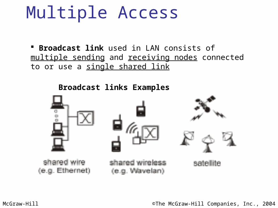
Broadcast link used in LAN consists of multiple sending and receiving nodes connected to or use a single shared link
Broadcast links Examples
McGraw-Hill ©The McGraw-Hill Companies, Inc., 2004
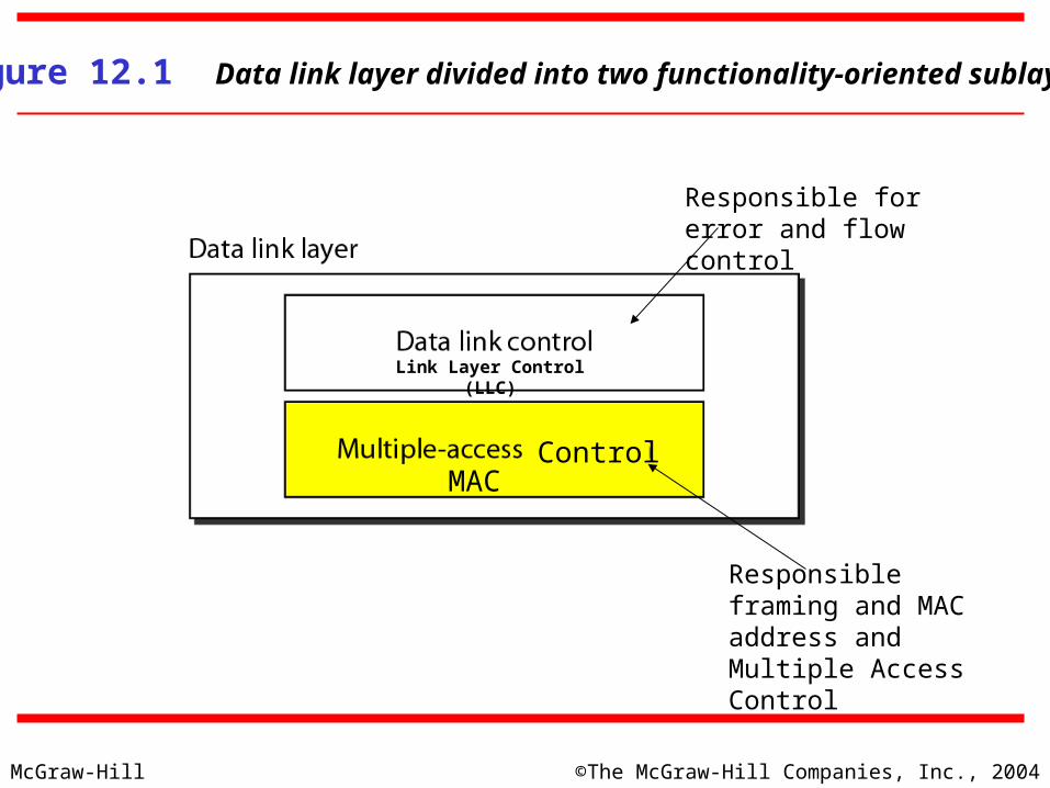
Figure 12.1 Data link layer divided into two functionality-oriented sublayers
Link Layer Control (LLC)
MAC
Responsible for error and flow control
Control
Responsible framing and MAC address and Multiple Access Control

McGraw-Hill ©The McGraw-Hill Companies, Inc., 2004
Multiple Access Problem: When two or more nodes transmit at the same time, their
frames will collide and the link bandwidth is wasted during collision
How to coordinate the access of multiple sending/receiving nodes to the shared link???
Solution: We need a protocol to coordinate the transmission of the active nodes
These protocols are called Medium or Multiple Access Control (MAC) Protocols belong to a sublayer of the data link layer called MAC (Medium Access Control)
What is expected from Multiple Access Protocols: Main task is to minimize collisions in order to utilize the bandwidth by:
Determining when a station can use the link (medium) what a station should do when the link is busy what the station should do when it is involved in collision
McGraw-Hill ©The McGraw-Hill Companies, Inc., 2004
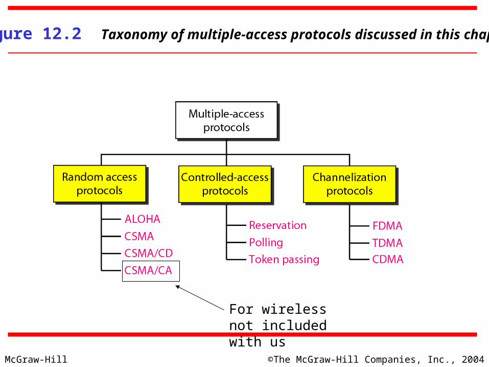
Figure 12.2 Taxonomy of multiple-access protocols discussed in this chapter
For wireless not included with us
McGraw-Hill ©The McGraw-Hill Companies, Inc., 2004
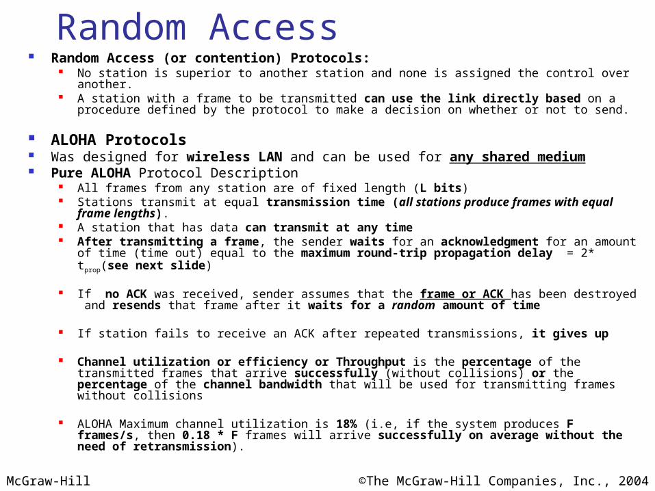
Random Access Random Access (or contention) Protocols:
No station is superior to another station and none is assigned the control over another. A station with a frame to be transmitted can use the link directly based on a procedure defined by the
protocol to make a decision on whether or not to send.
ALOHA Protocols Was designed for wireless LAN and can be used for any shared medium Pure ALOHA Protocol Description
All frames from any station are of fixed length (L bits) Stations transmit at equal transmission time (all stations produce frames with equal frame lengths). A station that has data can transmit at any time After transmitting a frame, the sender waits for an acknowledgment for an amount of time (time out)
equal to the maximum round-trip propagation delay = 2* tprop(see next slide)
If no ACK was received, sender assumes that the frame or ACK has been destroyed and resends that frame after it waits for a random amount of time
If station fails to receive an ACK after repeated transmissions, it gives up
Channel utilization or efficiency or Throughput is the percentage of the transmitted frames that arrive successfully (without collisions) or the percentage of the channel bandwidth that will be used for transmitting frames without collisions
ALOHA Maximum channel utilization is 18% (i.e, if the system produces F frames/s, then 0.18 * F frames will arrive successfully on average without the need of retransmission).

McGraw-Hill ©The McGraw-Hill Companies, Inc., 2004
Maximum Propagation Delay Maximum propagation delay(tprop): time it takes for a bit of a frame
to travel between the two most widely separated stations.
The farthest station
Station B receives the first bit of the frame at time t= tprop
McGraw-Hill ©The McGraw-Hill Companies, Inc., 2004
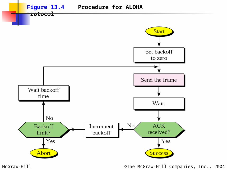
Figure 13.4 Procedure for ALOHA protocol
McGraw-Hill ©The McGraw-Hill Companies, Inc., 2004
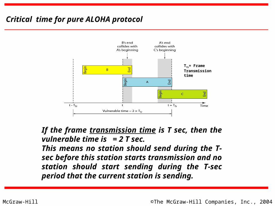
Critical time for pure ALOHA protocol
If the frame transmission time is T sec, then the vulnerable time is = 2 T sec. This means no station should send during the T-sec before this station starts transmission and no station should start sending during the T-sec period that the current station is sending.
Tfr= Frame Transmission time
McGraw-Hill ©The McGraw-Hill Companies, Inc., 2004
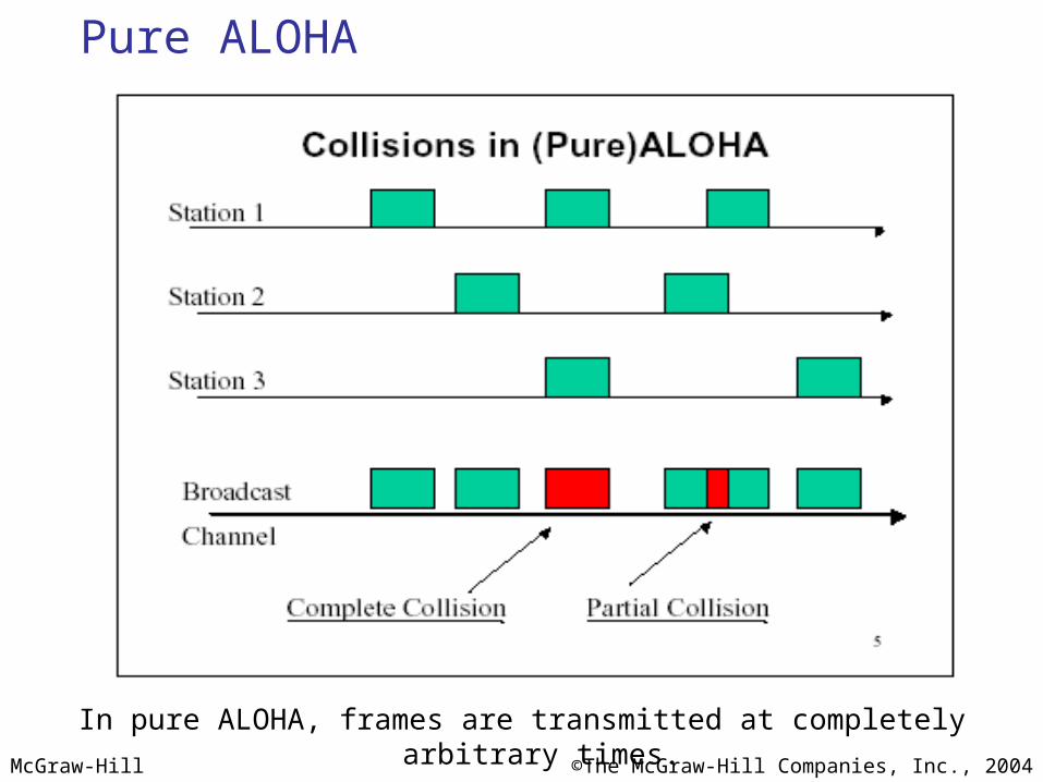
Pure ALOHA
In pure ALOHA, frames are transmitted at completely arbitrary times.

McGraw-Hill ©The McGraw-Hill Companies, Inc., 2004
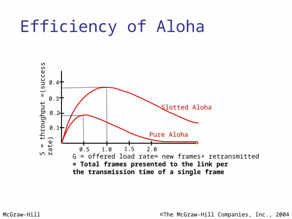
The throughput ( S) for pure ALOHA is S = G × e −2G .
The maximum throughputSmax = 0.184 when G= (1/2).
Note
G = Average number of frames generated by the system (all stations) during one frame transmission time
McGraw-Hill ©The McGraw-Hill Companies, Inc., 2004
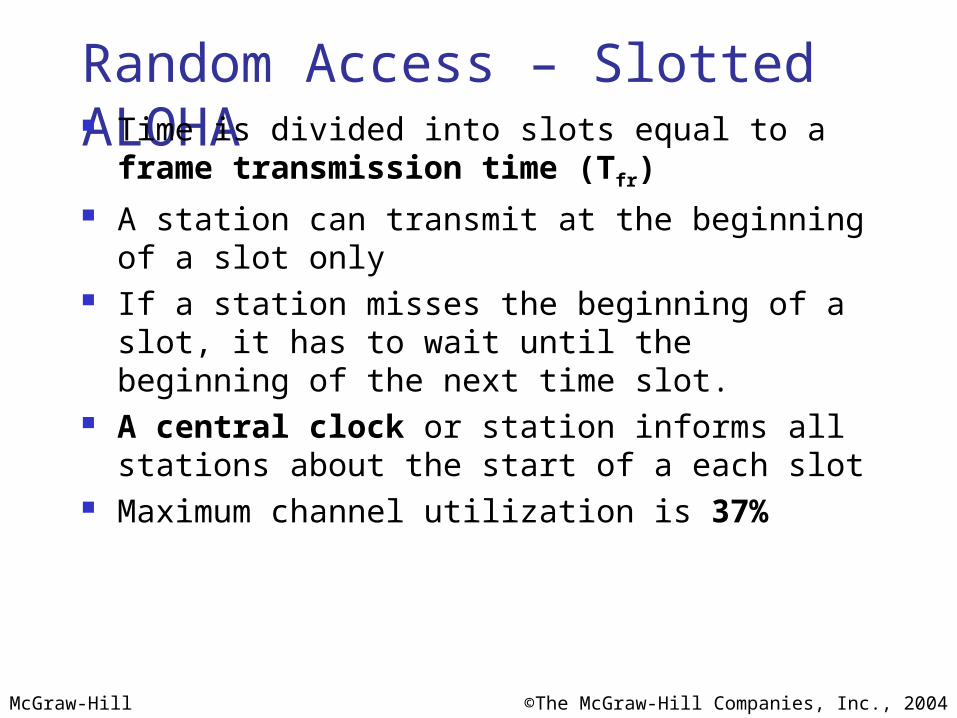
Random Access – Slotted ALOHA Time is divided into slots equal to a frame transmission
time (Tfr) A station can transmit at the beginning of a slot only If a station misses the beginning of a slot, it has to wait
until the beginning of the next time slot. A central clock or station informs all stations about the
start of a each slot Maximum channel utilization is 37%
McGraw-Hill ©The McGraw-Hill Companies, Inc., 2004
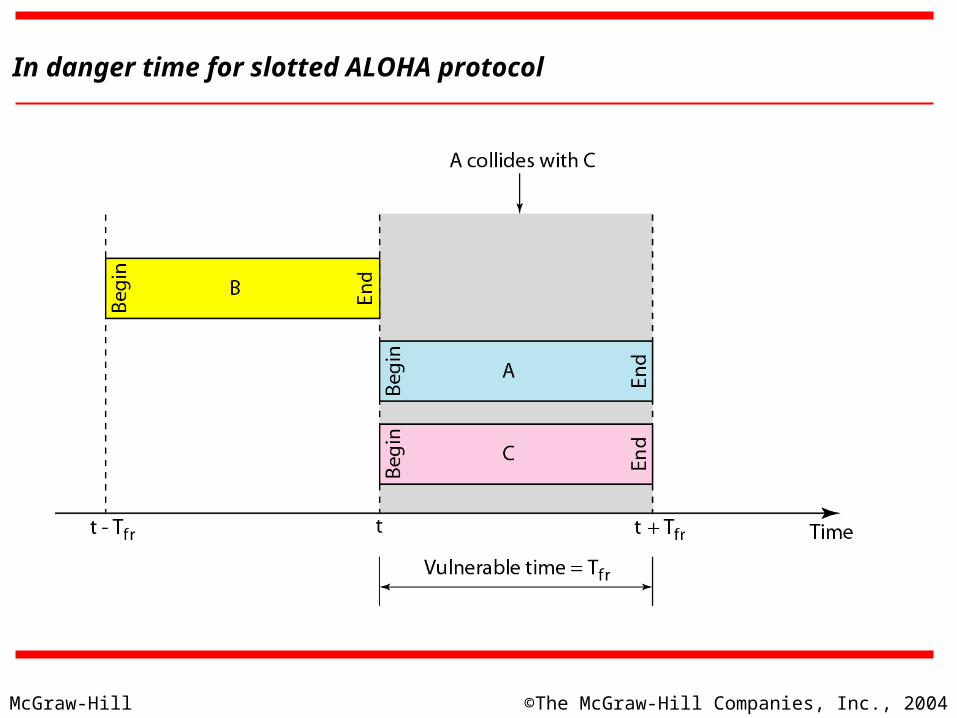
In danger time for slotted ALOHA protocol
McGraw-Hill ©The McGraw-Hill Companies, Inc., 2004
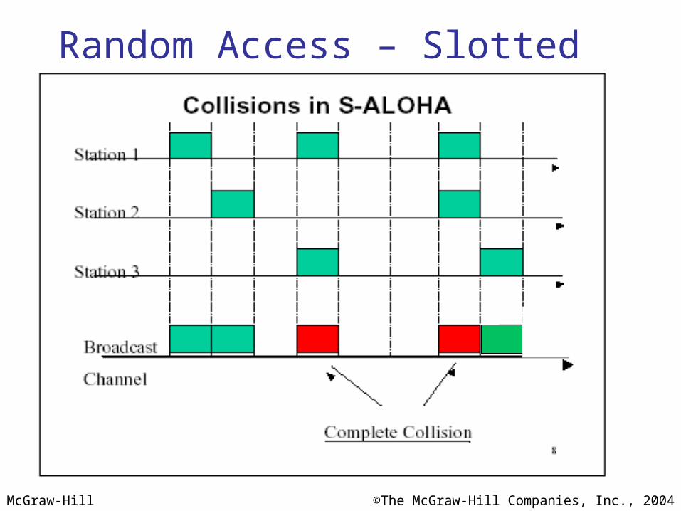
Random Access – Slotted ALOHA
McGraw-Hill ©The McGraw-Hill Companies, Inc., 2004
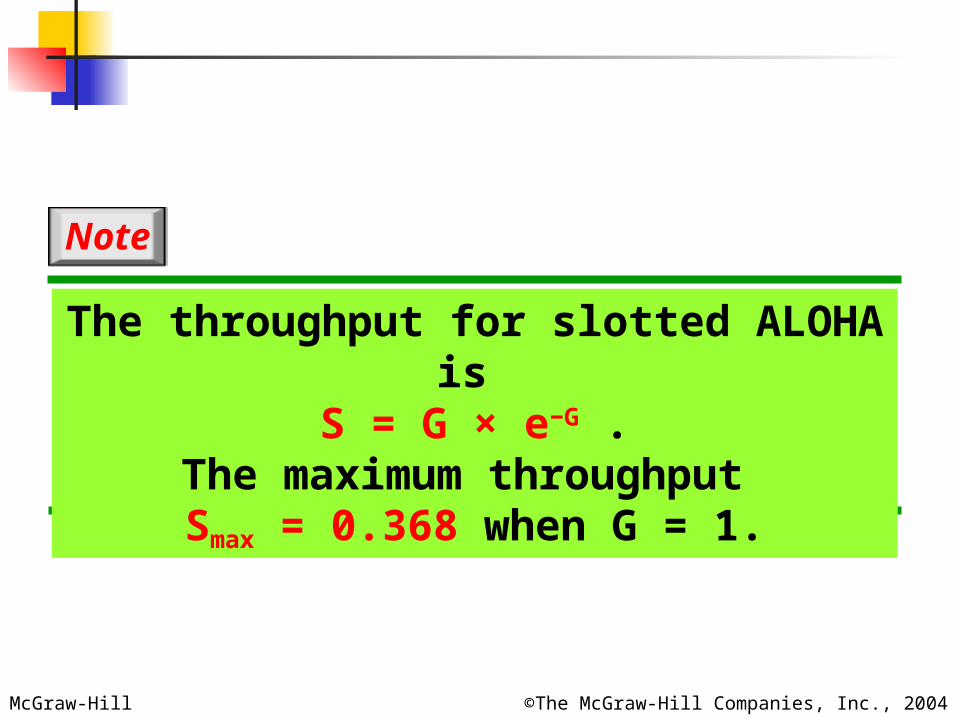
The throughput for slotted ALOHA is S = G × e−G .
The maximum throughput Smax = 0.368 when G = 1.
Note
McGraw-Hill ©The McGraw-Hill Companies, Inc., 2004
Efficiency of AlohaS =
thro
ughput
=(s
ucc
ess
ra
te)
G = offered load rate= new frames+ retransmitted= Total frames presented to the link per the transmission time of a single frame
0.5 1.0 1.5 2.0
0.1
0.2
0.3
0.4
Pure Aloha
Slotted Aloha
McGraw-Hill ©The McGraw-Hill Companies, Inc., 2004
Advantage of ALOHA protocolsA node that has frames to be transmitted can transmit continuously at the full rate of channel (R bps) if it is the only node with frames
Simple to be implemented
No master station is needed to control the medium
DisadvantageIf (M) nodes want to transmit, many collisions can occur and the rate allocated for each node will not be on average R/M bps
This causes low channel utilization
McGraw-Hill ©The McGraw-Hill Companies, Inc., 2004
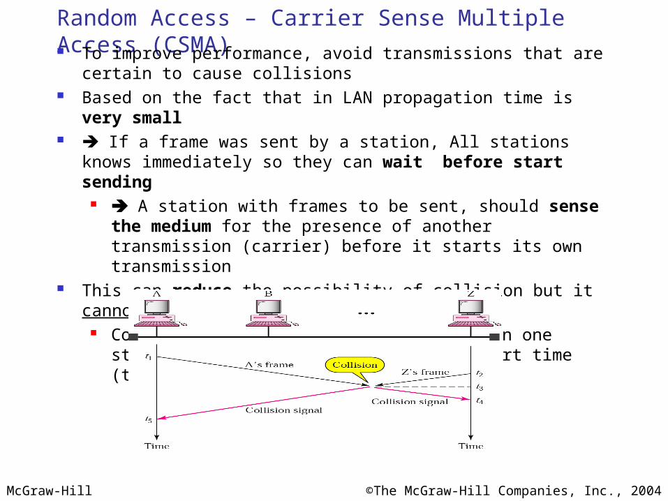
Random Access – Carrier Sense Multiple Access (CSMA) To improve performance, avoid transmissions that are certain to cause
collisions Based on the fact that in LAN propagation time is very small If a frame was sent by a station, All stations knows immediately so they
can wait before start sending A station with frames to be sent, should sense the medium for the
presence of another transmission (carrier) before it starts its own transmission
This can reduce the possibility of collision but it cannot eliminate it. Collision can only happen when more than one station begin transmitting
within a short time (the propagation time period)
McGraw-Hill ©The McGraw-Hill Companies, Inc., 2004
Random Access – Carrier Sense Multiple Access (CSMA)
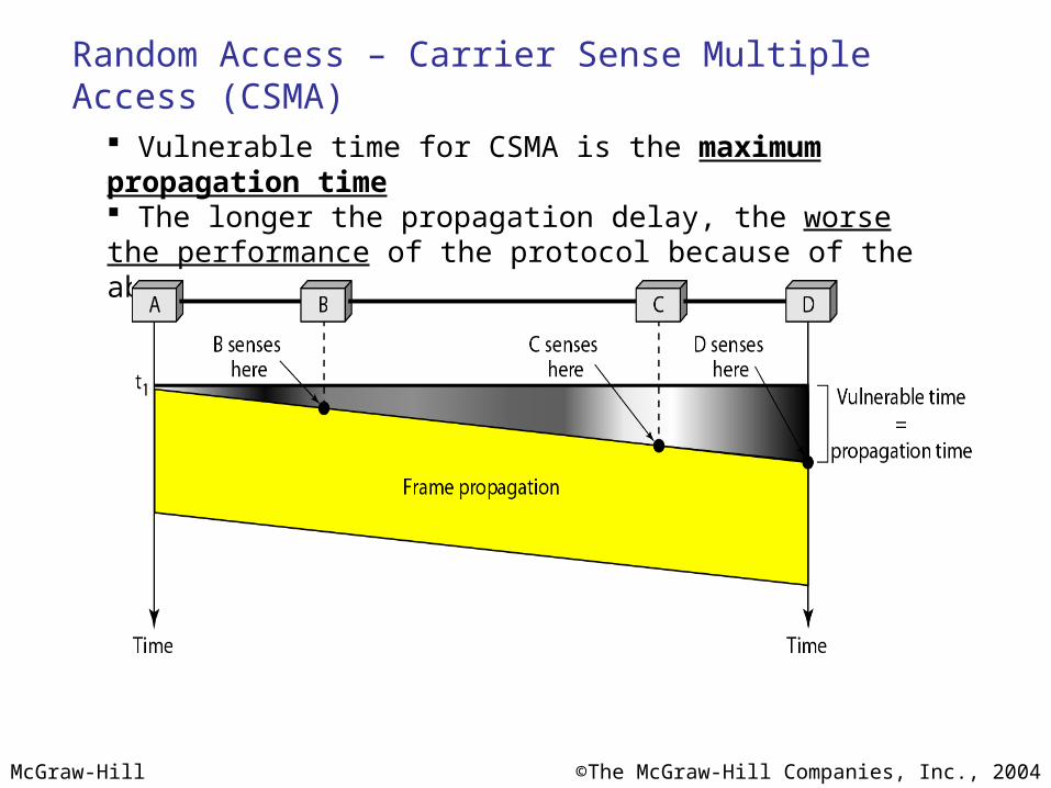
Vulnerable time for CSMA is the maximum propagation time The longer the propagation delay, the worse the performance of the protocol because of the above case.
McGraw-Hill ©The McGraw-Hill Companies, Inc., 2004
Types of CSMA Protocols
Different CSMA protocols that determine: What a station should do when the medium is idle? What a station should do when the medium is busy?
1. Non-Persistent CSMA
2. 1-Persistent CSMA
3. p-Persistent CSMA
McGraw-Hill ©The McGraw-Hill Companies, Inc., 2004
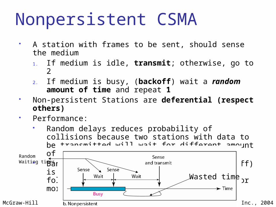
Nonpersistent CSMA A station with frames to be sent, should sense the medium
1. If medium is idle, transmit; otherwise, go to 22. If medium is busy, (backoff) wait a random amount of time and
repeat 1 Non-persistent Stations are deferential (respect others) Performance:
Random delays reduces probability of collisions because two stations with data to be transmitted will wait for different amount of times.
Bandwidth is wasted if waiting time (backoff) is large because medium will remain idle following end of transmission even if one or more stations have frames to send
Random Waiting times
Wasted time

McGraw-Hill ©The McGraw-Hill Companies, Inc., 2004
1-persistent CSMA To avoid idle channel time, 1-persistent protocol used Station wishing to transmit listens to the medium:
1. If medium idle, transmit immediately;
2. If medium busy, continuously listen until medium becomes idle; then transmit immediately with probability 1
Performance 1-persistent stations are selfish If two or more stations becomes ready at the same time, collision
guaranteed
McGraw-Hill ©The McGraw-Hill Companies, Inc., 2004
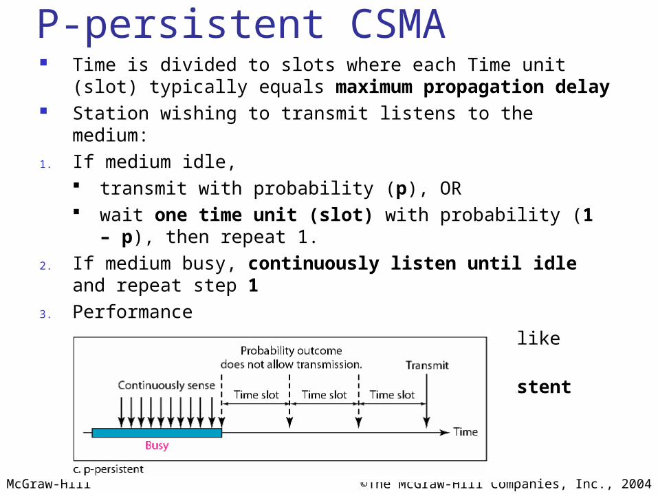
P-persistent CSMA Time is divided to slots where each Time unit (slot)
typically equals maximum propagation delay Station wishing to transmit listens to the medium:1. If medium idle,
transmit with probability (p), OR wait one time unit (slot) with probability (1 – p), then repeat 1.
2. If medium busy, continuously listen until idle and repeat step 1
3. Performance Reduces the possibility of collisions like nonpersistent Reduces channel idle time like 1-persistent
McGraw-Hill ©The McGraw-Hill Companies, Inc., 2004
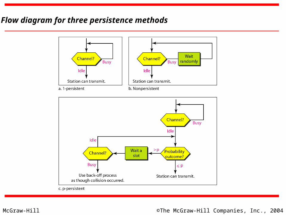
Flow diagram for three persistence methods
McGraw-Hill ©The McGraw-Hill Companies, Inc., 2004
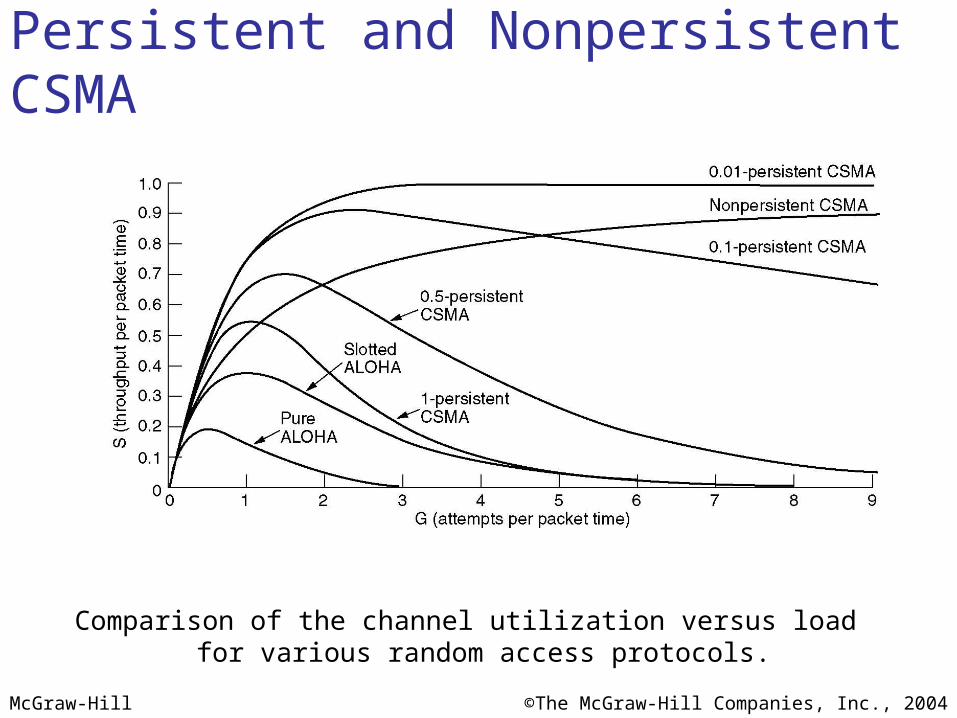
Persistent and Nonpersistent CSMA
Comparison of the channel utilization versus load for various random access protocols.
McGraw-Hill ©The McGraw-Hill Companies, Inc., 2004
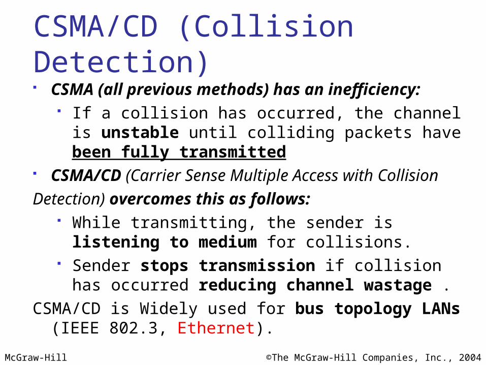
CSMA/CD (Collision Detection) CSMA (all previous methods) has an inefficiency:
If a collision has occurred, the channel is unstable until colliding packets have been fully transmitted
CSMA/CD (Carrier Sense Multiple Access with Collision
Detection) overcomes this as follows: While transmitting, the sender is listening to medium for
collisions. Sender stops transmission if collision has occurred
reducing channel wastage .
CSMA/CD is Widely used for bus topology LANs (IEEE 802.3, Ethernet).
McGraw-Hill ©The McGraw-Hill Companies, Inc., 2004
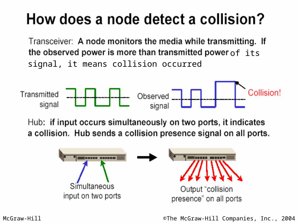
of its ownsignal, it means collision occurred
McGraw-Hill ©The McGraw-Hill Companies, Inc., 2004
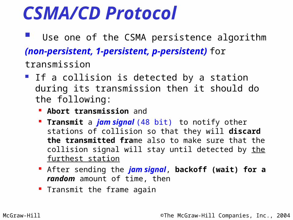
CSMA/CD Protocol Use one of the CSMA persistence algorithm
(non-persistent, 1-persistent, p-persistent) for
transmission If a collision is detected by a station during its
transmission then it should do the following: Abort transmission and Transmit a jam signal (48 bit) to notify other stations of collision
so that they will discard the transmitted frame also to make sure that the collision signal will stay until detected by the furthest station
After sending the jam signal, backoff (wait) for a random amount of time, then
Transmit the frame again
McGraw-Hill ©The McGraw-Hill Companies, Inc., 2004
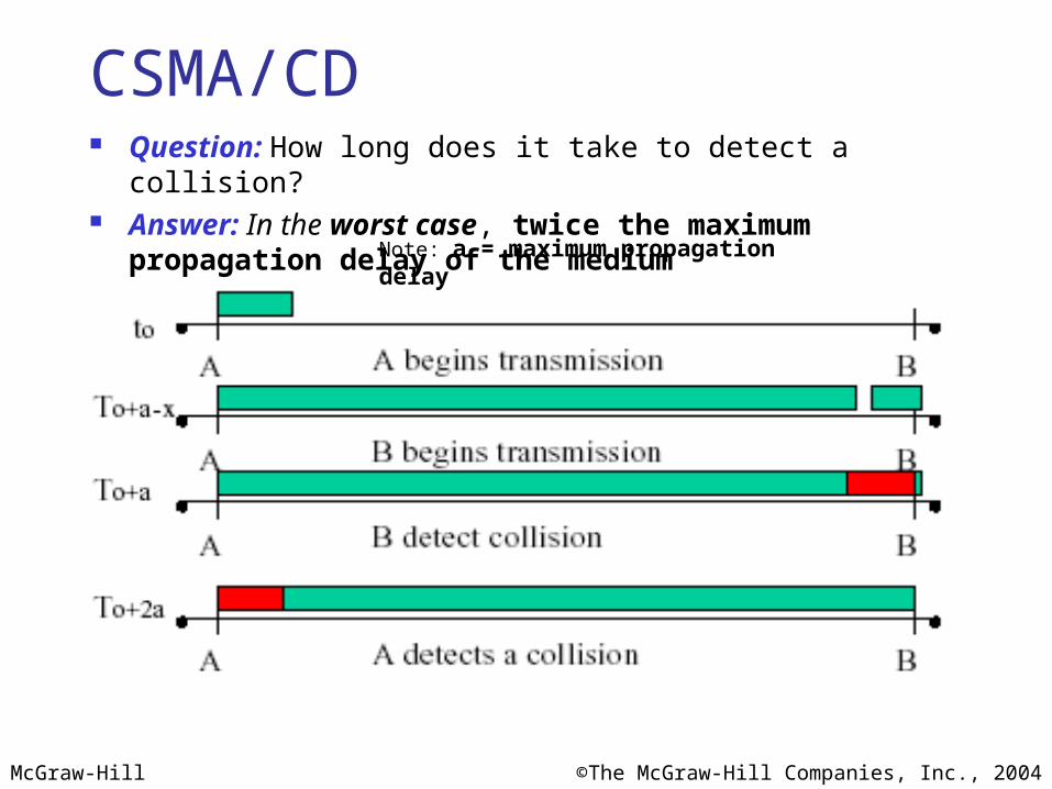
CSMA/CD Question: How long does it take to detect a collision? Answer: In the worst case, twice the maximum propagation delay
of the mediumNote: a = maximum propagation delay
McGraw-Hill ©The McGraw-Hill Companies, Inc., 2004
CSMA/CD
Restrictions of CSMA / CD: Packet transmission time should be at least as long as the time needed to
detect a collision (2 * maximum propagation delay + jam sequence transmission time)
Otherwise, CSMA/CD does not have an advantage over CSMA

McGraw-Hill ©The McGraw-Hill Companies, Inc., 2004
Exponential Backoff Algorithm Ethernet uses the exponential backoff algorithms to determine the
best duration of the random waiting period after the collision happens
Algorithm: Set “slot time” equal to 2*maximum propagation delay + Jam
sequence transmission time (= 51.2 usec for Ethernet 10-Mbps LAN)
After Kth collision, select a random number (R) between 0 and 2k –1 and wait for a period equal to (R*slot time) then retransmit
when the medium is idle, for example: After first collision (K=1), select a number (R) between 0 and 21 –1
{0 ,1} and wait for a period equal to R*slot times (Wait for a period 0 usec or 1x51.2 usec) then retransmit when the medium is idle
Do not increase random number range, if K=10 Maximum interval {0 – 1023}
Give up after 16 unsuccessful attempts and report failure to higher layers
McGraw-Hill ©The McGraw-Hill Companies, Inc., 2004
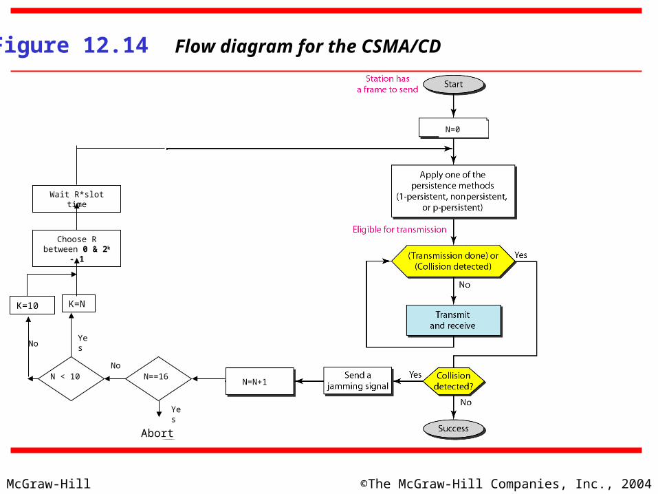
Figure 12.14 Flow diagram for the CSMA/CD
N=N+1
N=0
N==16
Abort
N < 10
K=NK=10
Choose R between 0 & 2k - 1
Wait R*slot time
No
No
Yes
Yes
McGraw-Hill ©The McGraw-Hill Companies, Inc., 2004
Exponential Backoff Algorithm
Reduces the chance of two waiting stations picking the same random waiting time
When network traffic is light, it results in minimum waiting time before transmission
As congestion increases ( traffic is high), collisions increase, stations backoff by larger amounts to reduce the probability of collision.
Exponential Back off algorithm gives last-in, first-out effect
Stations with no or few collisions will have the chance to transmit before stations that have waited longer because of their previous unsuccessful transmission attempts.
McGraw-Hill ©The McGraw-Hill Companies, Inc., 2004
Performance of Random Access Protocols Simple and easy to implement Decentralized (no central device that can fail and bring down the
entire system) In low-traffic, packet transfer has low-delay However, limited throughput and in heavier traffic, packet delay has
no limit. In some cases, a station may never have a chance to transfer its packet.
(unfair protocol)
A node that has frames to be transmitted can transmit continuously at the full rate of channel (R) if it is the only node with frames
If (M) nodes want to transmit, many collisions can occur and the rate for each node will not be on average R/M
McGraw-Hill ©The McGraw-Hill Companies, Inc., 2004
13.2 Controlled Access or Scheduling
Provides in order access to shared medium so that every station has chance to transfer (fair protocol)
Eliminates collision completely Three methods for controlled access:
Reservation Polling Token Passing
McGraw-Hill ©The McGraw-Hill Companies, Inc., 2004
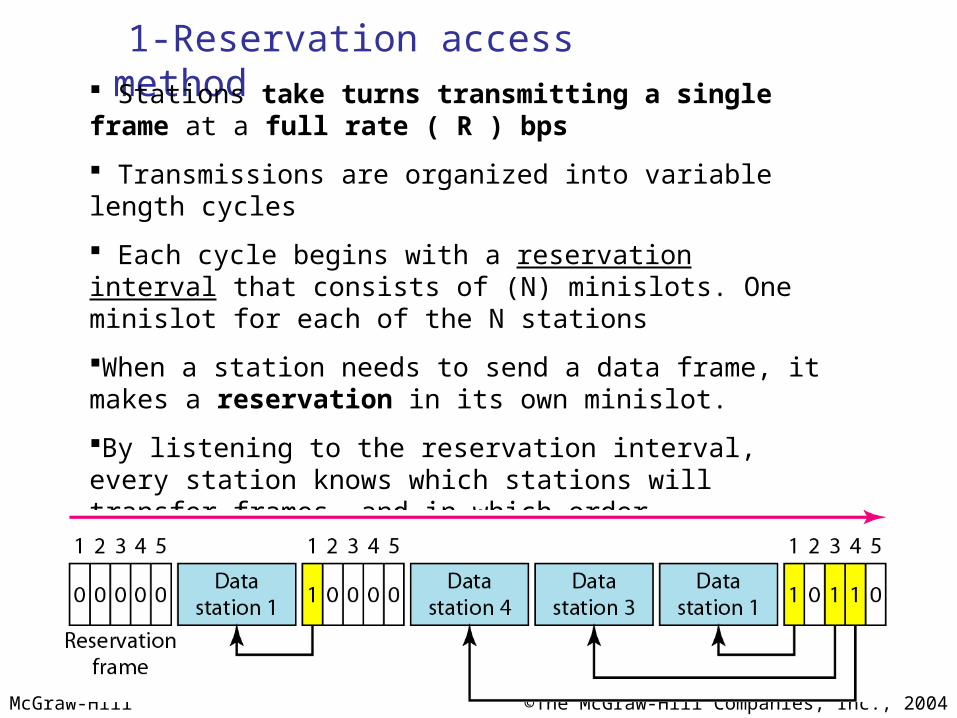
1-Reservation access method Stations take turns transmitting a single frame at a full rate ( R ) bps
Transmissions are organized into variable length cycles
Each cycle begins with a reservation interval that consists of (N) minislots. One minislot for each of the N stations
When a station needs to send a data frame, it makes a reservation in its own minislot.
By listening to the reservation interval, every station knows which stations will transfer frames, and in which order.
The stations that made reservations can send their data frames after the reservation frame.

McGraw-Hill ©The McGraw-Hill Companies, Inc., 2004
2- Polling
Stations take turns accessing the medium Two models: Centralized and distributed polling Centralized polling
One device is assigned as primary station and the others as secondary stations
All data exchanges are done through the primary When the primary has a frame to send it sends a select frame that
includes the address of the intended secondary When the primary is ready to receive data it send a Poll frame for each
device to ask if it has data to send or not. If yes, data will be transmitted otherwise NAK is sent.
Polling can be done in order (Round-Robin) or based on predetermined order
Distributed polling No primary and secondary Stations have a known polling order list which is made based on some
protocol station with the highest priority will have the access right first, then it
passes the access right to the next station (it will send a pulling message to the next station in the pulling list), which will passes the access right to the following next station, …

McGraw-Hill ©The McGraw-Hill Companies, Inc., 2004
Figure 12.19 Select and poll functions in polling access method
Primary is sending to Secondary Secondary is
sending to Primary
McGraw-Hill ©The McGraw-Hill Companies, Inc., 2004
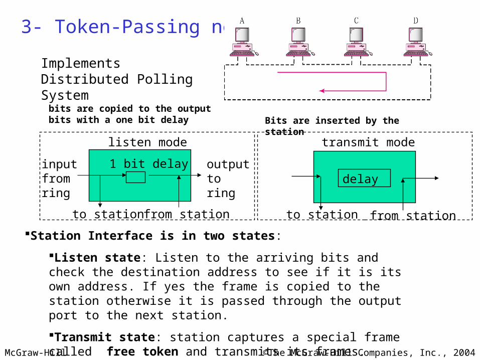
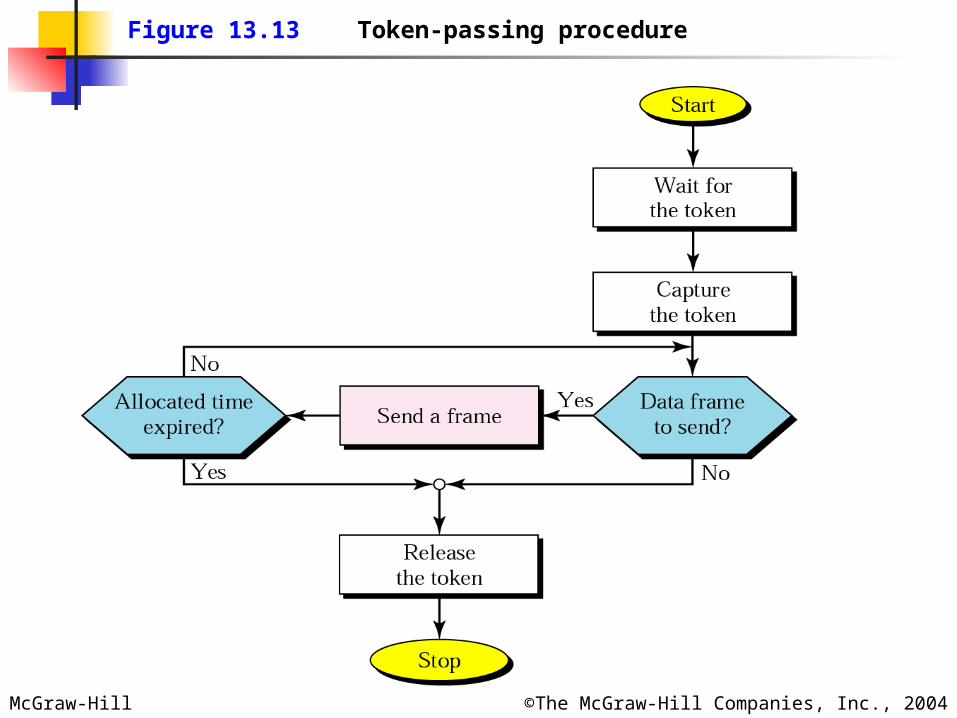
3- Token-Passing network
Station Interface is in two states:
Listen state: Listen to the arriving bits and check the destination address to see if it is its own address. If yes the frame is copied to the station otherwise it is passed through the output port to the next station.
Transmit state: station captures a special frame called free token and transmits its frames. Sending station is responsible for reinserting the free token into the ring medium and for removing the transmitted frame from the medium.
listen mode
1 bit delay
transmit mode
delay
to station from station
inputfromring
outputtoring
to station from station
Implements Distributed Polling System
Bits are inserted by the stationbits are copied to the output bits with a one bit delay
McGraw-Hill ©The McGraw-Hill Companies, Inc., 2004
Figure 13.13 Token-passing procedure
McGraw-Hill ©The McGraw-Hill Companies, Inc., 2004
12-3 CHANNELIZATION12-3 CHANNELIZATION
ChannelizationChannelization is a multiple-access method in which is a multiple-access method in which the available bandwidth of a link is shared in time, the available bandwidth of a link is shared in time, frequency, or through code, between different stations. frequency, or through code, between different stations. In this section, we discuss three channelization In this section, we discuss three channelization protocols.protocols.
Frequency-Division Multiple Access (FDMA)Time-Division Multiple Access (TDMA)Code-Division Multiple Access (CDMA)
Topics discussed in this section:Topics discussed in this section:
McGraw-Hill ©The McGraw-Hill Companies, Inc., 2004
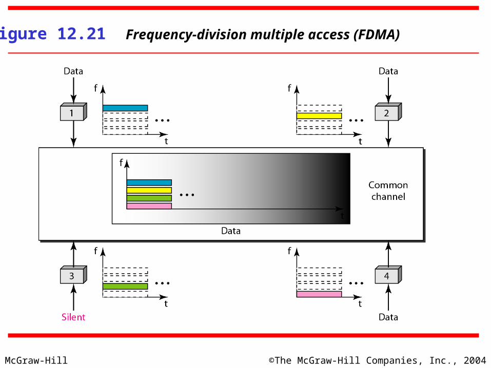
Figure 12.21 Frequency-division multiple access (FDMA)

McGraw-Hill ©The McGraw-Hill Companies, Inc., 2004
FDMA: Frequency Division Multiple Access: Transmission medium is divided into M separate frequency bands Each station transmits continuously on the assigned band at an average rate of
R/M A node is limited to an average rate equal R/M (where M is number of nodes)
even when it is the only node with frame to be sent
12-3 CHANNELIZATION - FDMA12-3 CHANNELIZATION - FDMA
McGraw-Hill ©The McGraw-Hill Companies, Inc., 2004
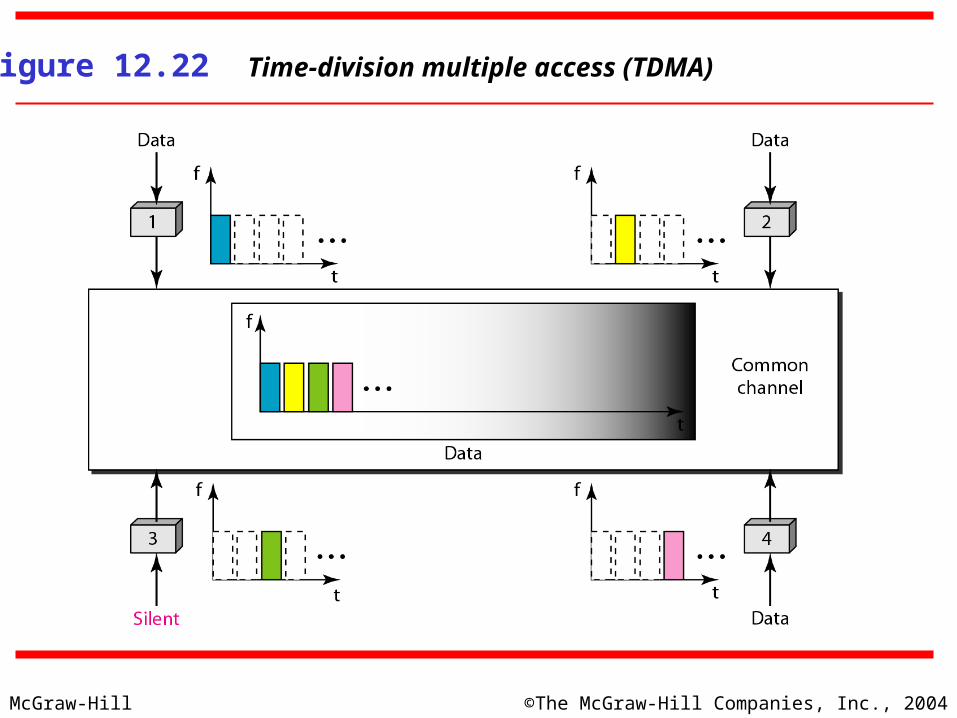
Figure 12.22 Time-division multiple access (TDMA)
McGraw-Hill ©The McGraw-Hill Companies, Inc., 2004
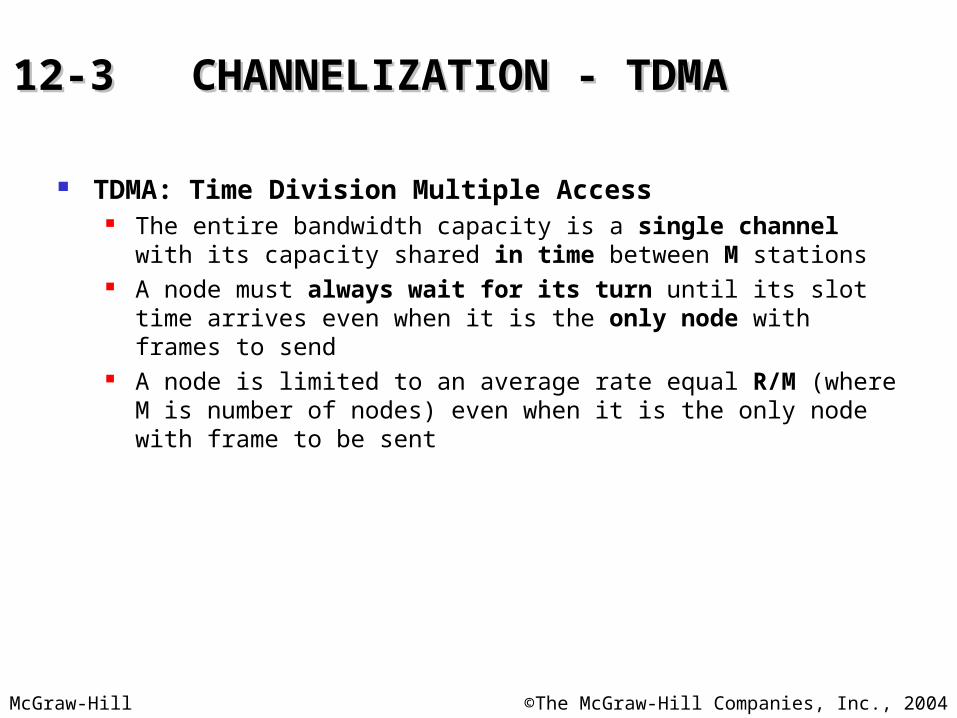
TDMA: Time Division Multiple Access The entire bandwidth capacity is a single channel with its capacity shared in
time between M stations A node must always wait for its turn until its slot time arrives even when it is
the only node with frames to send A node is limited to an average rate equal R/M (where M is number of nodes)
even when it is the only node with frame to be sent
12-3 CHANNELIZATION - TDMA12-3 CHANNELIZATION - TDMA

McGraw-Hill ©The McGraw-Hill Companies, Inc., 2004
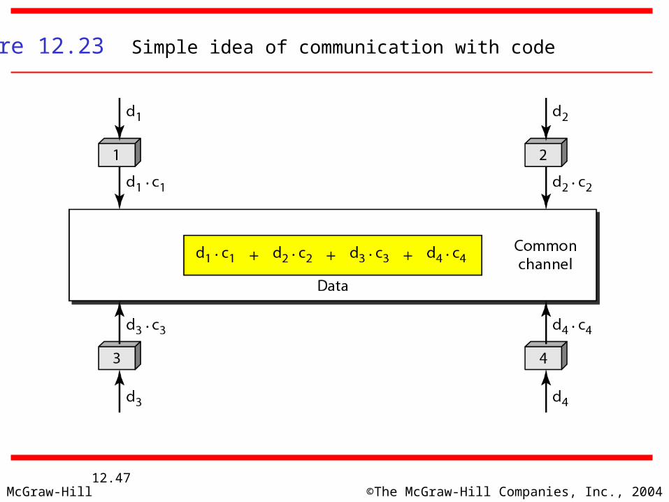
CDMA: Code Division Multiple Access In CDMA, one channel carries all transmissions simultaneously Each station codes its data signal by a specific codes before transmission The stations receivers use these codes to recover the data for the desired
station
12-3 CHANNELIZATION - CDMA12-3 CHANNELIZATION - CDMA
McGraw-Hill ©The McGraw-Hill Companies, Inc., 200412.47
Figure 12.23 Simple idea of communication with code