Embed Size (px)
Citation preview

UNIVERSITI TEKNOLOGI MALAYSIAInstitute of Environmental & Water Resource Management 1
MBR – Basic Engineering Design
Membrane Bioreactor TechnologyBasic engineering design
Technical presentation for WWE Sdn BhdKuala Lumpur November 7, 2003
Professor Zaini UjangPh.D., C.Eng.(UK), C.W.E.M. (UK), PPT

UNIVERSITI TEKNOLOGI MALAYSIAInstitute of Environmental & Water Resource Management 2
MBR – Basic Engineering Design
Presentation outline• Objectives• Which membrane systems?• Configurations• Aeration techniques• Activated sludge microbial populations• Biomass separation

UNIVERSITI TEKNOLOGI MALAYSIAInstitute of Environmental & Water Resource Management 3
MBR – Basic Engineering Design
Objectives?
• Organic removal• Organic removal and nitrification• Organic, nitrogen removal & water recycling• Organic and nutrient removal & water recycling• Persistent organic removal & water recycling• High strength waste management• Cleaner production

UNIVERSITI TEKNOLOGI MALAYSIAInstitute of Environmental & Water Resource Management 4
MBR – Basic Engineering Design
Objectives & systemsObjectives MBR Conventional
1 Not recommended WSP, CAS, RBC etc
2 Not recommended CAS, EA, RBC etc
3 Recommended AS + RO
4 Recommended AS + RO
5 Recommended (Hybrid MBR) AS + RO + GAC
6 Recommended (Hybrid MBR) Hybrid
7 Recommended (Hybrid MBR) Hybrid
1=Organic removal, 2=Organic removal and nitrification, 3=Organic, nitrogen removal & water recycling 4=Organic and nutrient removal & water recycling, 5=Persistent organic removal & water recycling, 6=High strength waste, 7 =Cleaner production

UNIVERSITI TEKNOLOGI MALAYSIAInstitute of Environmental & Water Resource Management 5
MBR – Basic Engineering Design
MBR processes
• Membrane separation bioreactors
• Membrane aeration bioreactors
• Extractive membrane bioreactors

UNIVERSITI TEKNOLOGI MALAYSIAInstitute of Environmental & Water Resource Management 6
MBR – Basic Engineering Design
MBR processesMembrane separation bioreactors – Submerged
Effluent
Bioreactor
Influent
Activated Sludge-Based Membrane System

UNIVERSITI TEKNOLOGI MALAYSIAInstitute of Environmental & Water Resource Management 7
MBR – Basic Engineering Design
MBR processesMembrane separation bioreactors – Side-stream
Effluent
SludgeReturn sludge
Primary clarifier Membrane Unit
Bioreactor
Sludge

UNIVERSITI TEKNOLOGI MALAYSIAInstitute of Environmental & Water Resource Management 8
MBR – Basic Engineering Design
MBR TechnologyMembrane separation bioreactors
Advantages Disadvantages-Small footprint -Aeration limitation-Complete solid removal -Membrane fouling-Effluent disinfection -Membrane costs-Removal of organic, nutrient & solid-High loading rate capability-Low/zero sludge production-Rapid start up-Sludge bulking not a problem-Modular/retrofit

UNIVERSITI TEKNOLOGI MALAYSIAInstitute of Environmental & Water Resource Management 9
MBR – Basic Engineering Design
MBR processesMembrane aeration bioreactors
Effluent
Bioreactor
InfluentOxygen
Bubbleless O transfer
Hollow fiber membrane
Gas Separation-Based Membrane System

UNIVERSITI TEKNOLOGI MALAYSIAInstitute of Environmental & Water Resource Management 10
MBR – Basic Engineering Design
MBR TechnologyMembrane aeration bioreactors
Advantages Disadvantages-High oxygen utilization -Membrane fouling-Highly efficient energy utilization -High capital cost-Small foot print -Unproven at full scale-Feed-forward control of O demand -Process complexity-Modular/retrofit

UNIVERSITI TEKNOLOGI MALAYSIAInstitute of Environmental & Water Resource Management 11
MBR – Basic Engineering Design
MBR processesMembrane extractive bioreactors
Effluent
Bioreactor
Gas Separation-Based Membrane SystemInfluent/Polluted materials
For recycling
Hollow fiber membrane
Treated wastewater

UNIVERSITI TEKNOLOGI MALAYSIAInstitute of Environmental & Water Resource Management 12
MBR – Basic Engineering Design
MBR TechnologyExtractive membrane bioreactors
Advantages Disadvantages
-Treatment of toxic industrial effluents -High capital cost
-Small effluents -Process complexity
-Modular/retrofit -Unproven at full scale
-Isolation of bacteria from wastewater

UNIVERSITI TEKNOLOGI MALAYSIAInstitute of Environmental & Water Resource Management 13
MBR – Basic Engineering Design
Performance comparison between activated sludge and MBR (Cicek et al., 1999)
Parameters Activated sludge MBRSludge age (d) 20 30COD removal (%) 94.5 99DOC removal (%) 92.7 97TSS removal (%) 60.9 99.9A-N removal 98.9 99.2Total P removal (%) 88.5 96.6Slude production (kg VSS/COD.d)
0.22 0.27
Mean floc size (µm) 20 3.5

UNIVERSITI TEKNOLOGI MALAYSIAInstitute of Environmental & Water Resource Management 14
MBR – Basic Engineering Design
Design criteria MBRParameters Design valuesLoading rates (for >90% organic removal)
1.2 to 3.2 kg COD/m3.d0.05 to 0.66 kg BOD/m3.d
Loading rates for complete nitrification
0.05 to 0.66 kg BOD/m3.dSludge age 10 to 50 d
Loading rate for complete nitrogen removal
4 kg NH4-N/m3.d5 kg NO3-N/m3.d
MLSS 10,000 to 20,000 mg/l
Flux 5 to 300 L/m2.h
Specific flux 20 to 200 L/ m2 h bar
Design flux (Kubota, φ of 0.4 µm) 0.5 m3/m2.d(specific flux 125-175 L/ m2 h bar)

UNIVERSITI TEKNOLOGI MALAYSIAInstitute of Environmental & Water Resource Management 15
MBR – Basic Engineering Design
Aerobic MBR Examples of design criteria
Wastewater Type V (m3)
HRT (h)
θ (d) Organic load
(kg/m3d)
MLSS(kg)
Sludge yield (d)
Air (m3/h)
Raw sewage (Ueda& Hata, 1999)
HF/S/PE
3.12 13.4 72 0.245 12.9 - 18
Municipal(Cote et al., 1997)
HF/S 1 4.8 - 2.3 26 0.2 0.5-1.5
Raw sewage (Ueda et al, 1999)
HF/S 21.4 13 120 0.315 12 - 42

UNIVERSITI TEKNOLOGI MALAYSIAInstitute of Environmental & Water Resource Management 16
MBR – Basic Engineering Design
Aerobic MBR configurations Examples of specific fluxes
Configurations Specific fluxes References
Submerged HF 50 to 65 L/m2.h.bar Gunder & Krauth, 1998
Flat plate 115 L/m2.h.bar Gunder & Krauth, 1998
Tubular side-stream 40 to 60 L/m2.h.bar Le Clech et al., 1999

UNIVERSITI TEKNOLOGI MALAYSIAInstitute of Environmental & Water Resource Management 17
MBR – Basic Engineering Design
MBR technology Materials and pore size
Pore size Materials
UF and MF submerged
0.02 to 0.5 µm Polyethylene, polypropylene, polysulphone etc
UF and MFSide-stream
0.02 to 0.5 µm Ceramics (MF), polyethylene,polypropylene, polysulphone etc
NF submerged <0.02 µm Polyethylene, polypropylene,polysulphone etc

UNIVERSITI TEKNOLOGI MALAYSIAInstitute of Environmental & Water Resource Management 18
MBR – Basic Engineering Design
Aerobic MBR: Energy consumption Pumping influent, recycling retente, permeate suction & aeration
Energy requirement References
MF submerged 0.2 to 0.4 kW.h/m3 Cote et al., 1998
MF side-stream 2 to 10 kW.h/m3 Cote et al., 1998
MF hollow fibre submerged
0.3 kW.h/m3
(0.28 for aeration)Cote et al., 1997
UNIVERSITI TEKNOLOGI MALAYSIAInstitute of Environmental & Water Resource Management 19
MBR – Basic Engineering Design
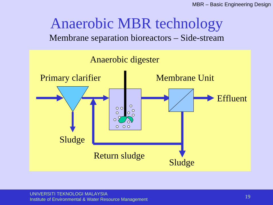
Anaerobic MBR technologyMembrane separation bioreactors – Side-stream
Effluent
SludgeReturn sludge
Primary clarifier Membrane Unit
Anaerobic digester
Sludge

UNIVERSITI TEKNOLOGI MALAYSIAInstitute of Environmental & Water Resource Management 20
MBR – Basic Engineering Design
Anaerobic MBRLoading rates
Parameters Values ReferencesSide-stream MBR -Loading rates (acidogenic)
54 kg COD/m3.d Anderson et al., 1986
Side-stream MBR - Loading rates (methanogenic)
12.2 kg COD/m3.d Anderson et al., 1986
Submerged MBR- Loading rates
15 kg COD/m3.d Li et al, 1985; Kayawake et al., 1991
HRT 67 h - POME124 h - maize waste

UNIVERSITI TEKNOLOGI MALAYSIAInstitute of Environmental & Water Resource Management 21
MBR – Basic Engineering Design
Typical values for the design parameters for activated sludge processes …
Process θ, d
F/M, lb BOD/ lb MLVSS.d
Volumetric loading,
lb BOD / 103 ft3.d
MLSS, mg/l
V/Q, h
Qr/Q
Conventional plug flow
3-15 0.2-0.6 20-40 1000-3000 4-8 0.25-0.75
Complete mix 0.75-15
0.2-1.0 50-120 800-6500 3.5 0.25-1.0
Step feed 3-15 0.2-0.5 40-60 1500-3500 3-5 0.25-0.75
Single-stage nitrification
8-12 0.10-0.2 5-20 1500-3500 6-15 0.5-1.5
Separate-stage nitrification
15-100 0.05-0.2 3-9 1500-3500 3-6 0.5-2

UNIVERSITI TEKNOLOGI MALAYSIAInstitute of Environmental & Water Resource Management 22
MBR – Basic Engineering Design
… Typical values for the design parameters for activated sludge processes
Process θ, d
F/M, lb BOD/ lb MLVSS.d
Volumetric loading,
lb BOD / 103 ft3.d
MLSS, mg/l
V/Q, h
Qr/Q
Contact stabilization
5-15 0.2-0.6 60-70 1000-3000 0.5-1 0.5-1.5
Extended aeration
20-40 0.04-0.1 5-15 2000-8000 18-36 0.5-1.5
Oxidation ditch
15-30 0.04-0.1 5-15 2000-8000 8-36 0.5-1.5
Intermittent decanted EA
12-25 0.04-0.08
5-15 2000-8000 20-40 NA
Sequencing batch reactor
10-30 0.04-0.1 5-15 2000-8000 12-50 NA

UNIVERSITI TEKNOLOGI MALAYSIAInstitute of Environmental & Water Resource Management 23
MBR – Basic Engineering Design
Design procedure for submerged MBR
Steps V/Q, h
Qr/Q
Wastewater characterization, and flow rate
0.5-1 0.5-1.5
Objectives? 18-36 0.5-1.5
Oxidation ditch 8-36 0.5-1.5
Intermittent decanted EA 20-40 NA
Sequencing batch reactor 12-50 NA


![Cannabis Health - [Nov/Dec 2003]](https://img.dokumen.tips/doc/110x75/546a96c3b4af9f7a2c8b4787/cannabis-health-novdec-2003.jpg)