Embed Size (px)
Citation preview

Chapter 8
Maximum Power Extraction fromUtility-Interfaced Wind Turbines
Ali M. Eltamaly, A. I. Alolah and Hassan M. Farh
Additional information is available at the end of the chapter
http://dx.doi.org/10.5772/54675
1. Introduction
Wind energy is one of the most promising renewable energy resources for producing electricitydue to its cost competitiveness compared to other conventional types of energy resources. Ittakes a particular place to be the most suitable renewable energy resources for electricityproduction. It isn't harmful to the environment and it is an abundant resource available innature. Hence, wind power could be utilized by mechanically converting it to electrical powerusing wind turbine, WT. Various WT concepts have a quick development of wind powertechnologies and significant growth of wind power capacity during last two decades. Variablespeed operation and direct drive WTs have been the modern developments in the technologyof wind energy conversion system, WECS. Variable-speed operation has many advantagesover fixed-speed generation such as increased energy capture, operation at MPPT over a widerange of wind speeds, high power quality, reduced mechanical stresses, aerodynamic noiseimproved system reliability, and it can provide (10-15) % higher output power and has lessmechanical stresses in comparison with the operation at a fixed speed [1, 2]. WTs can beclassified according to the type of drive train into direct drive (DD) and gear drive (GD). TheGD type uses a gear box, squirrel cage induction generator (SCIG) and classified as stall, activestall and pitch control WT and work in constant speed applications. The variable speed WTuses doubly-fed induction generator, (DFIG) especially in high power WTs. The gearless DDWTs have been used with small and medium size WTs employing permanent-magnetsynchronous generator (PMSG) with higher numbers of poles to eliminate the need for gearboxwhich can be translated to higher efficiency. PMSG appears more and more attractive, becausethe advantages of permanent magnet, (PM) machines over electrically excited machines suchas its higher efficiency, higher energy yield, no additional power supply for the magnet fieldexcitation and higher reliability due to the absence of mechanical components such as slip
© 2013 Eltamaly et al.; licensee InTech. This is an open access article distributed under the terms of theCreative Commons Attribution License (http://creativecommons.org/licenses/by/3.0), which permitsunrestricted use, distribution, and reproduction in any medium, provided the original work is properly cited.

rings. In addition, the performance of PM materials is improving, and the cost is decreasingin recent years. Therefore, these advantages make direct-drive PM wind turbine systems moreattractive in application of small and medium-scale wind turbines [1, 3-4].
Robust controller has been developed in many literatures [5-15] to track the maximum poweravailable in the wind. They include tip speed ratio (TSR) [5, 13], power signal feedback (PSF)[8, 14], and the hill-climb searching (HCS) [11-12] methods. The TSR control method regulatesthe rotational speed of the generator to maintain an optimal TSR at which power extracted ismaximum [13]. For TSR calculation, both the wind speed and turbine speed need to bemeasured, and the optimal TSR must be given to the controller. The first barrier to implementTSR control is the wind speed measurement, which adds to system cost and presents difficul‐ties in practical implementations. The second barrier is the need to obtain the optimal value ofTSR, this value is different from one system to another. This depends on the turbine-generatorcharacteristics results in custom-designed control software tailored for individual windturbines [14]. In PSF control [8, 14], it is required to have the knowledge of the wind turbine’smaximum power curve, and track this curve through its control mechanisms. The powercurves need to be obtained via simulations or off-line experiment on individual wind turbinesor from the datasheet of WT which makes it difficult to implement with accuracy in practicalapplications [7-8, 15]. The HCS technique does not require the data of wind, generator speedsand the turbine characteristics. But, this method works well only for very small wind turbineinertia. For large inertia wind turbines, the system output power is interlaced with the turbinemechanical power and rate of change in the mechanically stored energy, which often rendersthe HCS method ineffective [11-12]. On the other hand, different algorithms have been usedfor maximum power extraction from WT in addition to the three method mentioned above.For example, Reference [1] presents an algorithm for maximum power extraction and reactivepower control of an inverter through the power angle, δ of the inverter terminal voltage andthe modulation index, ma based variable-speed WT without wind speed sensor. Reference [16]presents an algorithm for MPPT via controlling the generator torque through q-axis currentand hence controlling the generator speed with variation of the wind speed. These techniquesare used for a decoupled control of the active and reactive power from the WT through q-axisand d-axis current respectively. Also, reference [17] presents a decoupled control of the activeand reactive power from the WT, independently through q-axis and d-axis current butmaximum power point operation of turbine system has been produced through regulating theinput dc current of the dc/dc boost converter to follow the optimized current reference [17].Reference [18] presents an algorithm for MPPT through directly adjusting duty ratio of the dc/dc boost converter and modulation index of the PWM- VSC. Reference [19] presents MPPTcontrol algorithm based on measuring the dc-link voltage and current of the uncontrolledrectifier to attain the maximum available power from wind. Finally, references [20-22] presentMPPT control based on a fuzzy logic control (FLC). The function of FLC is to track the generatorspeed with the reference speed for maximum power extraction at variable speeds. The MPPTalgorithms can be divided into two categories, the first one is MPPT algorithms for WT withwind speed sensor and the second one is MPPT algorithms without wind speed sensor(sensorless MPPT controller). Wind speed sensor normally used in conventional wind energyconversion systems, WECS [10, 23] for implementing MPPT control algorithm. This algorithm
New Developments in Renewable Energy160
increases cost and reduces the reliability of the WECS in addition to inaccuracies in measuringthe wind speed. Therefore, some MPPT control methods estimate the wind speed; however,many of them require the knowledge of air density and mechanical parameters of the WECS[88-92]. Such methods require turbine generator characteristics result in custom-designsoftware tailored for individual wind turbines. Air density, on the other hand, depends uponclimatic conditions and may vary considerably over various seasons. Therefore, this techniqueis not favorite in modern design of WT and a lot of research efforts are focused on developingwind speed sensorless MPPT controller which does not require the knowledge of air densityand turbine mechanical parameters [1, 9-11, 22-25]. Therefore, the cost and maintenance of thepower control system is decreased and implementation of the power control system is notdifficult compared to the sensored MPPT controller.
2. Wind Energy Conversion Systems (WECS)
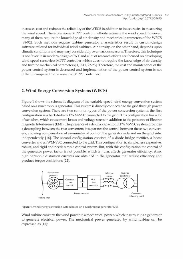
Figure 1 shows the schematic diagram of the variable-speed wind energy conversion systembased on a synchronous generator. This system is directly connected to the grid through powerconversion system. There are two common types of the power conversion systems, the firstconfiguration is a back-to-back PWM-VSC connected to the grid. This configuration has a lotof switches, which cause more losses and voltage stress in addition to the presence of Electro‐magnetic Interference (EMI). The presence of a dc-link capacitor in PWM-VSC system providesa decoupling between the two converters, it separates the control between these two convert‐ers, allowing compensation of asymmetry of both on the generator side and on the grid side,independently [16]. The second configuration consists of a diode-bridge rectifier, a boostconverter and a PWM-VSC connected to the grid. This configuration is, simple, less expensive,robust, and rigid and needs simple control system. But, with this configuration the control ofthe generator power factor is not possible, which in turn, affects generator efficiency. Also,high harmonic distortion currents are obtained in the generator that reduce efficiency andproduce torque oscillations [22].
Generator -side
converter
Grid-side
converter
Inductivereactor
Step-uptransformer
Power converter
Synchronousgenerator
Common collecting point
Turbine rotor
Figure 1. Wind energy conversion system based on a synchronous generator [26].
Wind turbine converts the wind power to a mechanical power, which in turn, runs a generatorto generate electrical power. The mechanical power generated by wind turbine can beexpressed as [15]:
Maximum Power Extraction from Utility-Interfaced Wind Turbineshttp://dx.doi.org/10.5772/54675
161

( ) 31 ,2m PP C Aul b r= (1)
where
Cp: Turbine power coefficient.
ρ: Air density (kg/m3).
A: Turbine sweeping area (m2).
u: wind speed (m/s).
λ: tip speed ratio of the wind turbine which is given by the following equation [1];
m rruw
l = (2)
Where rm is the turbine rotor radius, ωris the angular velocity of turbine (rad/s).
The turbine power coefficient, Cp, describes the power extraction efficiency of the wind turbine.It is a nonlinear function of both tip speed ratio, λ and the blade pitch angle, β. While itsmaximum theoretical value is approximately 0.59, it is practically between 0.4 and 0.45 [15].There are many different versions of fitted equations for Cp made in the literatures. A genericequation has been used to model Cp(λ, β) and based on the modeling turbine characteristicsas shown in the following equation [27]:
( )21
1, 0.5176 116 * 0.4 5 0.0068iP
iC e ll b b l
l
-æ ö= - - +ç ÷ç ÷
è ø(3)
With
31 1 0.035
0.08 1il l b b= -
+ +(4)
The Cp-λ characteristics, for different values of the pitch angle β, are illustrated in Figure 2.The maximum value of Cp is achieved for β = 0 degree and for λopt. The particular value of λis defined as the optimal value (λopt). Continuous operation of wind turbine at this pointguarantees the maximum available power which can be harvested from the available wind atany speed.
New Developments in Renewable Energy162

20 0
pC
l b
Figure 2. Aerodynamic power coefficient variation against λ and β.
2.1. Wind turbine arrangement with back-to-back PWM-VSCs
In this arrangement both the generator and the grid-side converters are PWM-VSCs as shownin Figure 3. The output voltage of the generator is converted into dc voltage through a PWM-VSC. As the previous model the dc-link voltage is converted to constant frequency voltageusing grid side PWM-VSC. The dc-link voltage is controlled by the modulation index (ma) andpower angle (δ). Controlling the dc-link voltage and the bitch angle of the blades of WT willtrack the maximum power of WT in the case of variable pitch angle control. In the case of fixedpitch angle control the maximum power extraction is achieved by tracking the optimum shaftspeed. The grid side PWM-VSC can be used to enhance the stability of the dc-link voltage andcontrols the active and reactive power from WT by controlling ma and δ. The generator can bedirectly controlled by the generator side converter (controller-1) while the grid-side converter(controller-2) maintains the dc-link voltage at the desired value by exporting active power tothe grid. Controller-2 also controls the reactive power exchange with the grid [26]. So, the maintarget of controller-1 is to track the maximum power available from the WTG and the functionof controller-2 is to control the dc-link voltage and the reactive power injected to the electricutility.
2.2. Wind turbine arrangement with diode-based rectifier
Figure 4 shows the wind turbine with a diode-based rectifier as the generator-side converter.The diode bridge rectifier converts the generator output ac power to dc power and the PWM-VSC converts the dc power from the rectifier output to ac power. One method to control theoperation of the wind turbine with this arrangement (assuming a PMSG) is illustrated in Figure4. A dc–dc converter is employed to control the dc-link voltage (controller-1), the grid sideconverter controls the operation of the generator and the power flow to the grid (controller-2).With appropriate control, the generator and turbine speed can be adjusted as wind speed variesso that maximum energy is collected [26]. On the other hand, in most PMSG wind systems,
Maximum Power Extraction from Utility-Interfaced Wind Turbineshttp://dx.doi.org/10.5772/54675
163

the output voltage of the generator is converted into dc voltage via a full-bridge diode rectifierand this dc voltage is adjusted to control the maximum power of turbine. The grid sideconverter is controlled by grid injected active and reactive power control method. The ac poweroutput from PMSG is fed to a three-phase diode bridge forward by boost converter toeffectively control the dc voltage level through the duty ratio of boost converter. The PWM-VSC is used to interface the WTG with the electrical utility also to track the maximum poweravailable from PMSG. The modulation index of the PWM-VSC is controlled to enhance thestability of the dc link voltage as shown in Figure 4.
Controller -1 Controller -2
dc–dcconverter
Figure 4. Wind turbine generator with a diode-based rectifier as the generator-side converter [26].
3. MPPT control strategies for the WECS
WECS has been attracting wide attention as a renewable energy source due to depleting fossilfuel reserves and environmental concerns as a direct consequence of using fossil fuel andnuclear energy sources. Wind energy varies continually as wind speed changes throughout
Controller -1 Controller -2
Figure 3. Wind turbine generator with back-to-back PWM-VSCs [26].
New Developments in Renewable Energy164

the day, even though abundant. The Amount of power output from a WECS depends uponthe accuracy of tracking the peak power points using the MPPT controller irrespective of thegenerator type used. The maximum power extraction algorithms can be classified into twocategories. The two categories are MPPT algorithms with wind speed sensor and MPPTalgorithms without wind speed sensor (sensor-less MPPT controller). These two algorithmshave been discussed in the following sections.
3.1. MPPT algorithms for a WT with wind speed sensor
3.1.1. Tip Speed Ratio (TSR) technique
The TSR control method regulates the rotational speed of the generator to maintain an optimalTSR at which power extracted is maximum [13]. The target optimum power extracted fromwind turbine can be written as [14]:
3max *opt optP K w= (5)
WhereKopt =0.5 * ρ A * ( rmλopt
)3* CP−max, and ωopt =
λoptrm
* u
The power for a certain wind speed is maximum at a certain value of rotational speed calledoptimum rotational speed,ωopt. This optimum rotational speed corresponds to optimum tipspeed ratio, λopt. In order to track maximum possible power, the turbine should always operateat λopt. This is achieved by controlling the rotational speed of the WT so that it always rotatesat the optimum rotational speed. As shown in Figure 5, for TSR calculation, both the windspeed and turbine speed need to be measured, and the optimal TSR must be given to thecontroller. The first barrier to implement TSR control is the wind speed measurement, whichadds to system cost and presents difficulties in practical implementations. The second barrieris the need to obtain the optimal value of TSR, this value is different from one system to another.This depends on the turbine-generator characteristics results in custom-designed controlsoftware tailored for individual wind turbines [14].
optl
÷
ControllerWind Energy
system
gw
Reference Tip-speed
ratio
Load Power
Generator Speed, gwWind SpeedRg *w
actl
Figure 5. The block diagram of the tip speed ratio control of WECS [15].
Maximum Power Extraction from Utility-Interfaced Wind Turbineshttp://dx.doi.org/10.5772/54675
165

3.1.2. Power Signal Feedback (PSF) control
In PSF control [14], it is required to have the knowledge of the wind turbine’s maximum powercurve, and track this curve through its control mechanisms. The maximum power curves needto be obtained via simulations or off-line experiment on individual wind turbines or from thedatasheet of WT which makes it difficult to implement with accuracy in practical applications.In this method, reference power is generated using a maximum power data curve or using themechanical power equation of the wind turbine where wind speed or the rotational speed isused as the input. Figure 6 shows the block diagram of a WECS with PSF controller formaximum power extraction. The PSF control block generates the optimal power command Popt
which is then applied to the grid side converter control system for maximum power extractionas follow [15]:
3*opt opt rP K w= (6)
The actual power output, Pt is compared to the optimal power, Popt and any mismatch is usedby the fuzzy logic controller to change the modulation index of the grid side converter, PWM-VSC as shown in Figure 6. The PWM-VSC is used to interface the WT with the electrical utilityand will be controlled through the power angle, δ and modulation index, ma to control theactive and reactive power output from the WTG [15].
ControllerWind Energy
system
rw
Turbine power,
rwRotational Speed ,
tP
optP
rw
optPLookup Table
Figure 6. The block diagram of power signal feedback control [15].
3.1.3. Optimal torque control
The aim of the torque controller is to optimize the efficiency of wind energy capture in a widerange of wind velocities, keeping the power generated by the machine equal to the optimaldefined value. It can be observed from the block diagram represented in Figure 7, that the ideaof this method is to adjust the PMSG torque according to the optimal reference torque of thewind turbine at a given wind speed. A typical wind turbine characteristic with the optimaltorque-speed curve plotted to intersect the CP-max points for each wind speed is illustrated inFigure 8. The curve Topt defines the optimal torque of the device (i.e. maximum energy capture),
New Developments in Renewable Energy166

and the control objective is to keep the turbine on this curve as the wind speed varies. For anywind speed, the MPPT device imposes a torque reference able to extract the maximum power.The curve Topt is defined by [26]:
2*opt opt optT K w= (7)
Where
3
max0.5 * * *mopt P
opt
rK A Cr
l -
æ öç ÷=ç ÷è ø
(8)
optK
×
2gw
ControllerWind Energy
system
gwReference
Torque
Generator Torque
Figure 7. The block diagram of optimal torque control MPPT method.
12 m/s
10 m/s
8 m/s
6 m/s
Generator speed
Gen
erat
or to
rque 14 m/s
Maximum torque curve (Topt)
Rated torque
Figure 8. Wind turbine characteristic for maximum power extraction [26].
3.1.4. Load angle control
The load angle control can be explained by analyzing the transfer of active and reactive powerbetween two sources connected by an inductive reactance as shown in Figure 9. The active
Maximum Power Extraction from Utility-Interfaced Wind Turbineshttp://dx.doi.org/10.5772/54675
167

power, PS, and reactive power, QS, transferred from the sending-end to the receiving-end canbe calculated from the following equation [26]:
sins Rs
gen
V VP
Xd= (9)
2s s R
sgen gen
V V VQ
X X= - (10)
PWMGrid
0sV dRV
Rs
genref
sgen
VVXP
=d
refsgenP
s
g enre fsg en
SR VXQ
VV -=sV
0=r e fs g e nQ
sR VV =
sgenP
genX
Figure 9. Load angle control of the generator-side converter [26].
3.1.4.1. Load angle control of the generator-side converter
The operation of the generator and the power transferred to the dc-link are controlled byadjusting the magnitude and angle of the voltage at the ac terminals of the generator-sideconverter. This can be achieved using the load angle control technique where the internalvoltage of the generator is the sending source (Vs∠0), and the generator-side converter is thereceiving source (VR∠δ). The inductive reactance between these two sources is the synchronousreactance of the generator, Xgen, as shown in Figure 9 [26].
If it is assumed that the load angle δ is small, then sin δ ≈ δ and cos δ ≈ 1, Then the voltagemagnitude, VR, and angle magnitude, δ, required at the terminals of the generator-sideconverter are calculated using Equations (7) and (8) as shown [26]:
refSgen gen
S R
P XV V
d = (11)
refSgen gen
R SS
Q XV V
V= - (12)
New Developments in Renewable Energy168

Where PSgenref is the reference value of the active power that needs to be transferred from the
generator to the dc-link, and QSgenref is the reference value for the reactive power. The reference
value PSgenref is obtained from the characteristic curve of the machine for maximum power
extraction for a given generator speed, ωr. As the generator has permanent magnets, it doesnot require magnetizing current through the stator, thus the reactive power reference valuecan be set to zero, QSgen
ref = 0 (i.e. VS and VR are equal in magnitude). The implementation of thisload angle control scheme is illustrated in Figure 9. The major advantage of the load anglecontrol is its simplicity. However, as the dynamics of the generator are not considered it maynot be very effective in controlling the generator during transient operation [26].
3.1.4.2. Load angle control for the grid-side converter
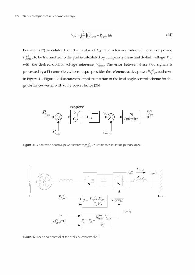
The objective of the grid-side converter controller is to maintain the dc-link voltage at thereference value by exporting active power to the grid. In addition, the controller is designedto enable the exchange of reactive power between the converter and the grid as required bythe application specifications. Also, the load angle control is a widely used grid side convertercontrol method, where the grid-side converter is the sending source (VS∠δ), and the grid is thereceiving source (VR∠0). As known, the grid voltage is selected as the reference; hence, thephase angle δ is positive. The reactance Xgrid is the inductor coupling between these two sources[26]. The reference value for the active power,PSgrid
ref , that needs to be transmitted to the gridcan be determined by examining the dc-link dynamics with the aid of Figure 10.
gensPgridsP
cPGeneratoroutputpower
Powertransmittedto the grid
C+
_dcV
Figure 10. Power flow in the dc-link [26].
This figure illustrates the power balance at the dc-link [26] as shown in the following equation:
C Sgen SgridP =P -P (13)
where PC is the power across the dc-link capacitor, C, PSgen is the active power output of thegenerator (and transmitted to the dc-link), and PSgrid is the active power transmitted from thedc-link to the grid.
The dc-link voltage Vdc can be expressed in terms of the generator output power, PSgen, and thepower transmitted to the grid, PSgrid, as shown in the following [26]:
Maximum Power Extraction from Utility-Interfaced Wind Turbineshttp://dx.doi.org/10.5772/54675
169
( )2dc Sgen SgridV P P dt
C= -ò (14)
Equation (12) calculates the actual value of Vdc. The reference value of the active power,
PSgridref , to be transmitted to the grid is calculated by comparing the actual dc-link voltage, Vdc,
with the desired dc-link voltage reference, Vdc-ref. The error between these two signals is
processed by a PI-controller, whose output provides the reference active powerPSgridref , as shown
in Figure 11. Figure 12 illustrates the implementation of the load angle control scheme for the
grid-side converter with unity power factor [26].
gensP
gridsP
DCVC2
Integrator
refDCV
PIController
refsgrid
P
Figure 11. Calculation of active power reference,PSgridref , (suitable for simulation purposes) [26].
PWMGrid
dsV 0RV
Rs
gridref
sgrid
VVXP
=dref
SgridP
sgridP
gridX
s
gridref
sgridRs V
XQVV +=0=ref
sgridQVR
Vs=VR
Figure 12. Load angle control of the grid-side converter [26].
New Developments in Renewable Energy170

3.2. MPPT algorithms for a WT without wind speed sensor
3.2.1. Hill-Climb Searching (HCS)
3.2.1.1. Principle of Hill-Climb Searching (HCS)
The HCS [11], control algorithm continuously searches for the peak power of the wind turbine.The maximum power can be extracted from WTG without requiring information about thewind and generator speeds (Hill-Climb Searching, HCS) [1, 11]. It can overcome some of thecommon problems normally associated with the other two methods, TSR and PSF. The trackingalgorithm depends on the location of the operating point. According to the changes in powerand speed the desired optimum signal has been computed in order to track the point ofmaximum power. Figure 13 shows the principle of HCS control where the operating point ismoving toward or away from the maximum turbine power according to increasing (down-hillregion) or decreasing the dc current, Idm (up-hill region). The down-hill and up-hill regions arenamed according to the trend of the system output power with respect to the inverter dc-linkvoltage, Vdc for a wind energy system. If an increase of Idm leads to an increase of the systemoutput power, the HCS method considers the turbine running in the down-hill region, and Idm
should keep increasing toward the maximum power point; otherwise, the turbine is consideredas running in the up-hill region, and Idm decreasing will be the choice of the HCS method towrdsthe maximum power point [11].
Figure 13. HCS control principle [11].
3.2.1.2. Advanced Hill-Climb Searching (HCS) method
Reference [11] introduces an advanced hill climb searching, AHCS which has been proposedto maximize Pm, through detecting the inverter output power and inverter dc-link voltage. Theauthors use a diode rectifier to convert the three-phase output ac voltage of a generator to Vdc
as shown in Figure 14.
Maximum Power Extraction from Utility-Interfaced Wind Turbineshttp://dx.doi.org/10.5772/54675
171

dc–dcconverter
Synchronousgenerator
Variable speed Wind Turbine
Rectifier Inverter
Utility systemPower Electronic converter
Wind Power Generation System Maximum Power Control System
Electrical loads
Figure 14. Typical wind power generation system connected to a utility grid [11].
Vdc is related to the generator angular rotational speed (ωr) by a function of the generator fieldcurrent (If) and the load current (Ig) as shown [11]:
( , ) *dc f g rV k I I w= (15)
The algorithm uses the relationship between the turbine mechanical power (Pm), and theelectrical system output power (Pout) given by Equation (14). By differentiating Equation (14)to get a relationship for ΔPm, Equation (15) is obtained:
* * * *r out rm load f r r f r r
d P dP P T J T J
dt dtw w
w w w wh
= + + = + + (16)
* ( * )out rm f r r
P dP T J
dtw
w wh
DD = + D + D (17)
Authors noted that if the sampling period of the control system is adequately small then theterm k(If, Ig ) can be considered as a constant value k during a sampling period. Tf *ω and η canalso be considered as constant values in the same sampling period. Based on the aboveassumptions, Equation (15) leads to Equation (16) for digital control purposes.
2 * ( * )out dcm dc
P dVP JK V
dthD
D = + D (18)
In order to establish rules to adjust the system’s operating point, this method evaluates thevalues of ΔPout and Δ(Vdc*dVdc/dt) (which represents Δ(ωr*dωr/dt) ) based on Equation (14).Depending on the values of ΔPout and Δ(Vdc*dVdc/dt) the polarity of the inverter current demandcontrol signal (Idm) is decided according to Equation (16). There are three basic modes for thismethod, i) initial mode, ii) training mode, and iii) application mode as shown in Figure 15.
New Developments in Renewable Energy172

Mode Swich Rules
Direct currentDemon control
(Memory access)
AHCS&
Memory Updating Rules
Max-Power ErrorDriven Control
Application ModeTraining ModeInitial Mode
dtdPout
outPdt
dVdcdcV
dmI
Figure 15. Structure of the intelligent maximum wind power extraction algorithm [11].
During its initial mode, before the algorithm has been trained, the magnitude of Idm is deter‐mined by the maximum power error driven (MPED) control. MPED control is the implemen‐tation of the conventional HCS method in terms of wind energy system characteristics. Duringits training mode, the algorithm continually records and updates operating parameters intoits programmable lookup table for its intelligent memory feature. Since this method is trainablewith its intelligent memory, it allows itself to adapt to work with different WT. As a result, itis a solution to the customization problems of many algorithms. Another advantage of thisalgorithm is that it does not require mechanical sensors (like anemometers) which lowers itscost and eliminates its associated practical problems. However, it can be seen in [11] that thealgorithm is relatively slow and complex as it has three different modes of operation. Anotherdrawback is that the algorithm cannot take into account of the changes in air density, whichaffects the power characteristics quite significantly.
3.2.2. MPPT algorithm by directly adjusting the DC/DC converter duty cycle and modulation indexof the PWM-VSC
MPPT Algorithm by Directly Adjusting the dc/dc Converter duty ratio, D, and ModulationIndex of the PWM-VSC, ma, is shown in Figure 16. In this direct drive converter, the mechanicalpower from the WT model is fed to the PMSG. The three-phase output voltages of the PMSGare fed to the three- phase diode bridge rectifier. There is no control on the output voltage ofthe diode bridge rectifier so it cannot be connected directly to the PWM because the PWMinverter needs constant dc voltage. So, a dc/dc converter should be used to control the dc-linkvoltage. Depending on the dc output voltage required from the dc/dc converter, boost or buckconverter can be used. In this study, the dc output voltage, Vd,out is required to be higher thaninput dc voltage, Vd,in, so the boost converter is used. By controlling the dc voltage to be constantby controlling of D the boost converter and ma the maximum available power from the windcan be extracted. The main drawback of this system is the diode bridge and boost converterare unidirectional power flow devices, so the PMSG has to work only in generator mode whichmay affect the stability of the system at abnormal conditions. A high capacitance of the dc linkcapacitor can remedy the effects of this drawback [18].
Maximum Power Extraction from Utility-Interfaced Wind Turbineshttp://dx.doi.org/10.5772/54675
173

BoostconverterPMSG
Grid-sideconverter
Inductivereactor
Wind turbine Commoncollecting pointBridge
rectifier
Figure 16. Modelling of wind turbine driving permanent magnet synchronous generator.
The active and reactive power can be obtained in terms of ma and D of the boost converter asshown in Equation (17) and Equation (18), respectively [18].
,3 sin
2 2 (1 )a d in LLU
outs
m V VP
D X
d*=
-(19)
, ,3 3cos
2 2 (1 ) 2 2 (1 )a d in a d in
out LLUs
m V m VQ V
D X Dd
æ öç ÷= * -ç ÷- -è ø
(20)
Where;
δ: torque angle at the electric utility side.
Xs: synchronous reactance of the electric utility.
It is clear from Equation (17) and Equation (18) that the active and reactive power can becontrolled by controlling modulation index, ma of the PWM inverter and duty ratio of the boostconverter.
3.2.3. Maximum power extraction and reactive power technique
3.2.3.1. Decoupled control of the active and reactive power, dependently
This method presents an algorithm for maximum power extraction and reactive power controlof an inverter based variable-speed wind-turbine generator without wind speed sensor. Thealgorithm does not require information about the wind and generator speeds or the inverter dc-link voltage and thus, is dependent of specifications of the wind turbine generation system [1].
Consider the wind-turbine generation system of Figure 17. The turbine mechanical power Pm
and the generator output power Pg are related by
* *r out rm r r
d P dP Pg J J
dt dtw w
w wh
= + = + (21)
New Developments in Renewable Energy174

where Pout is the converter output power, ωr is the generator speed, J is the combined turbineand generator moment of inertia and η is the overall system efficiency.
dc–dcconverter
Synchronousgenerator
Wind Turbine Rectifier Inverter Utility system
Figure 17. Grid-connected wind-turbine generation system [1].
A. Real power
This part shows how a maximum power can be extracted from a WTG without requiringinformation about the wind and generator speeds. In the system of Figure 17, the converterdc-link voltage is proportional to the generator speed, Vdc = Kωr, since the generator terminalvoltage is proportional to the speed. Thus, Equation (19) can be expressed in terms of Vdc as [1]:
2out dc
m dcP dVJP V
dtKh= + (22)
Taking the derivative of Equation (20), we deduce
2 ( )out dcm dc
P dVJP VdtKh
DD = + D (23)
Vdc is proportional to the inverter terminal voltage Vinv divided by the inverter amplitudemodulation index, ma. Thus,ΔVdc =Δ(V inv / ma).To extract maximum power from the wind, asmall perturbation is applied to the angle of the inverter terminal voltage, δ. ΔPoutandΔ(V inv / ma) are estimated and their signs determine whether the operating point is movingtoward or away from the maximum turbine power, Figure 18. Depending on the operatingpoint direction of movement, the decision is to increase or decrease the angle δ or to keep itconstant. Table 1 describes the decision that is made based on the sign of the inverter outputpower variation ΔPoutand that of the ratio of the inverter terminal voltage to the amplitudemodulation indexΔ(V inv / ma). With the proposed algorithm for maximum power extraction,only voltage and current at the inverter terminal need to be measured, and no informationabout the wind and generator speeds and the dc-link voltage is required [1].
Maximum Power Extraction from Utility-Interfaced Wind Turbineshttp://dx.doi.org/10.5772/54675
175

Turbine shaft velocityTu
rbin
e po
wer
Up HILL Down HILL
Figure 18. Wind turbine output power versus speed [1].
ΔPout Δ(V invma
) Decision
> 0 > 0 Increase δ
< 0 < 0 Decrease δ
> 0 < 0 No change
< 0 > 0 No change
Table 1. Maximum power tracking algorithm [1].
B. Reactive power
The inverter should be able to regulate its output reactive power to provide the reactive powerdemand of the utility system, Figure 17. The inverter output reactive power must be controlledso as the maximum real power extraction is not violated. The real and reactive power compo‐nents (Pout, Qout ) at the inverter output terminals are [1]:
sin( )inv sysout
T
V VP
Xd= (24)
( )2cos( ) sysinv sys
outT T
VV VQ
X Xd= - (25)
Vsys is the utility system voltage and XT is the reactance between the inverter and the utilitysystem. It is seen from Equation (22) and Equation (23) that Vinv and δ can be controlled so asQout is regulated at a desired value while Pout is kept constant at its maximum corresponding
to the wind speed. Substituting Vinv in Equation (22) by 3
2 2 ma Vd, This equation can be
deduced as follow:
New Developments in Renewable Energy176

3sin( )
2 2a dc sys
outT
m V VP
Xd= (26)
Assuming that Vdc does not change over the small sampling period T, Pout corresponding to thesampling time nT and (n +1)T is
( )( )
3sin( )
2 2a n dc sys
out n nT
m V VP
Xd= (27)
( 1)( 1) 1
3sin( )
2 2a n dc sys
out n nT
m V VP
Xd+
+ += (28)
To keep the real power constant, i.e., Pout (n+1) = Pout (n), while providing a desired reactive power,Equation (23), the inverter voltage angle must satisfy the following condition.
( )11
( 1)sin sin( )a n
n na n
mm
d d-+
+
é ù= ê ú
ê úë û(29)
Figure 19 shows a flowchart of the proposed algorithm for maximum power extraction andreactive power control of a wind-turbine generator. The inputs are the three-phase voltagesand currents at the inverter output terminals and the outputs are the required amplitudemodulation index and the voltage angle of the inverter.
3.2.3.2 Decoupled control of the active and reactive power, independently
In this study [17], simple ac-dc-ac power conversion system and proposed modular controlstrategy for grid-connected wind power generation system have been implemented. Grid-sideinverter maintains the dc-link voltage constant and the power factor of line side can beadjusted. Input current reference of dc/dc boost converter is decided for the maximum powerpoint tracking of the turbine without any information of wind or generator speed. As theproposed control algorithm does not require any speed sensor for wind or generator speed,construction and installation are simple, cheap, and reliable. The main circuit and control blockdiagrams are shown in Figure 20. For wide range of variable speed operation, a dc-dc boostconverter is utilized between 3-phase diode rectifier and PWM-VSC. The input dc current isregulated to follow the optimized current reference for maximum power point operation ofturbine system. Grid PWM-VSC supply currents into the utility line by regulating the dc-linkvoltage. The active power is controlled by q-axis current through regulating the dc-link voltagewhereas the reactive power can be controlled by d-axis current via adjusting the power factor
Maximum Power Extraction from Utility-Interfaced Wind Turbineshttp://dx.doi.org/10.5772/54675
177
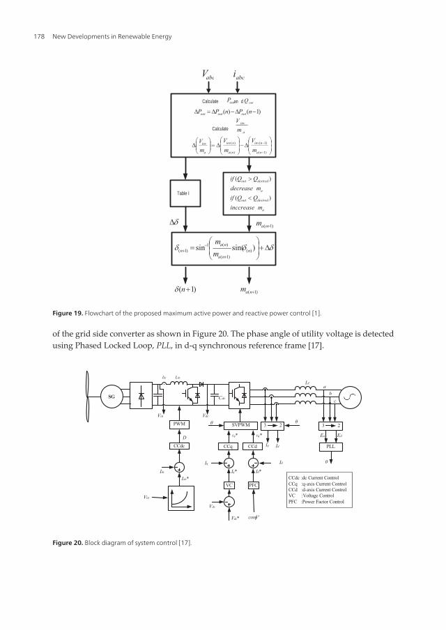
of the grid side converter as shown in Figure 20. The phase angle of utility voltage is detectedusing Phased Locked Loop, PLL, in d-q synchronous reference frame [17].
PWM SVPWM
SG
LdcIdc
VdcVin
Cdc
Vin
Idc*Idc
CCdcD
Vdc*
Vdc
VC
Iq*
Iq
CCq
Vq*
PFC
Id*
CCd
Vq*
cosɸº
Id
θ 3 2
IdIq
3 2
EdEq
PLL
θ
θ
CCdc :dc Current Control CCq :q-axis Current Control CCd :d-axis Current Control VC :Voltage Control PFC :Power Factor Control
ab
c
LF
Figure 20. Block diagram of system control [17].
Calculate an d
Calculate
Table I
outP
abcV abci
outQ
)1()( -D-D=D nPnPP outoutout
a
inv
mV
÷÷ø
öççè
æD-÷
÷ø
öççè
æD=÷÷
ø
öççè
æD
-
-
)1(
)1(
)(
)(
na
ninv
na
ninv
a
inv
mV
mV
mV
a
desiredout
a
desiredout
minccreaseQQif
mdecreaseQQif
)(
)(
dD )1( +nam
ddd D+÷÷ø
öççè
æ=
+
-+ )sin(sin )(
)1(
)(1)1( n
na
nan m
m
)1( +nam)1( +nd
Figure 19. Flowchart of the proposed maximum active power and reactive power control [1].
New Developments in Renewable Energy178

4. Co-simulation (PSIM/Matlab) program for interconnecting wind energysystem with electric utility
In this study, the WECS is designed as PMSG connected to the grid via a back-to-back PWM-VSC as shown in Figure 21. MPPT control algorithm has been introduced using FLC to regulatethe rotational speed to force the PMSG to work around its maximum power point in speedsbelow rated speeds and to produce the rated power in wind speed higher than the rated windspeed of the WT. Indirect vector-controlled PMSG system has been used for this purpose. Theinput to FLC is two real time measurements which are the change of output power androtational speed between two consequent iterations (ΔP, and Δωm). The output from FLC isthe required change in the rotational speed Δωm-new*. The detailed logic behind the newproposed technique is explained in details in the following sections. Two effective computersimulation software packages (PSIM and Simulink) have been used to carry out the simulationeffectively where PSIM contains the power circuit of the WECS and Matlab/Simulink containsthe control circuit of the system. The idea behind using these two different software packagesis the effective tools provided with PSIM for power circuit and the effective tools in Simulinkfor control circuit and FLC.
Generator - sidecontroller
PMSGGenerator-side
converterGrid-side converter
Utility grid
Grid- sidecontroller
Figure 21. Schematic diagram of the overall system.
4.1. Wind energy conversion system description
Figure 22 shows a co-simulation (PSIM/Simulink) program for interconnecting WECS toelectric utility. The PSIM program contains the power circuit of the WECS and Matlab/Simulink program contains the control of this system. The interconnection between PSIM andMatlab/Simulink has been done via the SimCoupler block. The basic topology of the powercircuit which has PMSG driven wind turbine connected to the utility grid through the ac-dc-ac conversion system is shown in Figure 21. The PMSG is connected to the grid through back–to-back bidirectional PWM voltage source converters VSC. The generator side converter isused as a rectifier, while the grid side converter is used as an inverter. The generator sideconverter is connected to the grid side converter through dc-link capacitor. The control of theoverall system has been done through the generator side converter and the grid side converter.
Maximum Power Extraction from Utility-Interfaced Wind Turbineshttp://dx.doi.org/10.5772/54675
179

MPPT algorithm has been achieved through controlling the generator side converter usingFLC. The grid-side converter controller maintains the dc-link voltage at the desired value byexporting active power to the grid and it controls the reactive power exchange with the grid.
SimCoupler Block(Power circuit)
Generator-side controller
Grid-side controller
Simuliink(control circuit )
FromPSIM
ToPSIM
Figure 22. Co-simulation block of wind energy system interfaced to electric utility.
4.1.1. Wind turbine model
Wind turbine converts the wind power to a mechanical power. This mechanical powergenerated by wind turbine at the shaft of the generator can be expressed as:
( ) 31 ,2m PP C Aul b r= (30)
where ρ is the air density (typically 1.225 kg/m3), β is the pitch angle (in degree), A is the areaswept by the rotor blades (in m2); u is the wind speed (in m/s) and Cp(λ, β) is the wind-turbinepower coefficient (dimensionless).
The turbine power coefficient, Cp(λ, β), describes the power extraction efficiency of the WT andis defined as the ratio between the mechanical power available at the turbine shaft and thepower available in wind. A generic equation shown later in Equation (3) is used to modelCp(λ, β). CP is a nonlinear function of both tip speed ratio, λ and the blade pitch angle, β. Thetip speed ratio, λ is the ratio of the turbine tip speed, ωm*R to the wind speed, u. This tip speedratio, λ, is defined as [28]:
*m Ru
wl = (31)
Where ωm is the rotational speed and R is the turbine blade radius, respectively.
New Developments in Renewable Energy180
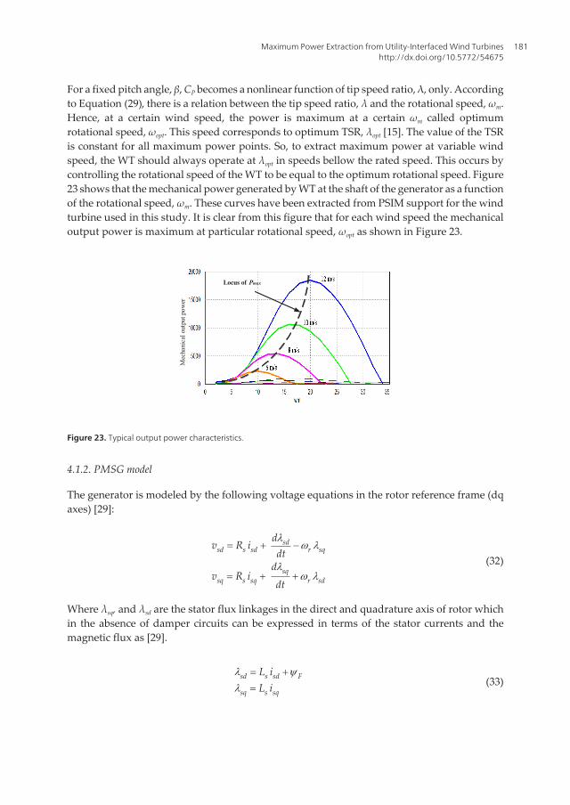
For a fixed pitch angle, β, CP becomes a nonlinear function of tip speed ratio, λ, only. Accordingto Equation (29), there is a relation between the tip speed ratio, λ and the rotational speed, ωm.Hence, at a certain wind speed, the power is maximum at a certain ωm called optimumrotational speed, ωopt. This speed corresponds to optimum TSR, λopt [15]. The value of the TSRis constant for all maximum power points. So, to extract maximum power at variable windspeed, the WT should always operate at λopt in speeds bellow the rated speed. This occurs bycontrolling the rotational speed of the WT to be equal to the optimum rotational speed. Figure23 shows that the mechanical power generated by WT at the shaft of the generator as a functionof the rotational speed, ωm. These curves have been extracted from PSIM support for the windturbine used in this study. It is clear from this figure that for each wind speed the mechanicaloutput power is maximum at particular rotational speed, ωopt as shown in Figure 23.
Mec
hani
cal o
utpu
t pow
er
Locus of Pmax
Figure 23. Typical output power characteristics.
4.1.2. PMSG model
The generator is modeled by the following voltage equations in the rotor reference frame (dqaxes) [29]:
sdsd s sd r sq
sqsq s sq r sd
dv R i
dtd
v R idt
lw l
lw l
= + -
= + +(32)
Where λsq, and λsd are the stator flux linkages in the direct and quadrature axis of rotor whichin the absence of damper circuits can be expressed in terms of the stator currents and themagnetic flux as [29].
sd s sd F
sq s sq
L iL i
l yl
= +
= (33)
Maximum Power Extraction from Utility-Interfaced Wind Turbineshttp://dx.doi.org/10.5772/54675
181
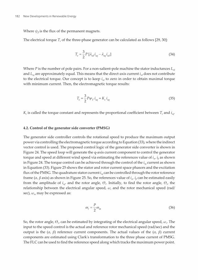
Where ψF is the flux of the permanent magnets.
The electrical torque Te of the three-phase generator can be calculated as follows [29, 30]:
3 [ ]2e sd sq sq sdT P i il l= - (34)
Where P is the number of pole pairs. For a non-salient-pole machine the stator inductances Lsd
and Lsq are approximately equal. This means that the direct-axis current isd does not contributeto the electrical torque. Our concept is to keep isd to zero in order to obtain maximal torquewith minimum current. Then, the electromagnetic torque results:
32e F sq c sqT P i K iy= = (35)
Kc is called the torque constant and represents the proportional coefficient between Te and isq.
4.2. Control of the generator side converter (PMSG)
The generator side controller controls the rotational speed to produce the maximum outputpower via controlling the electromagnetic torque according to Equation (33), where the indirectvector control is used. The proposed control logic of the generator side converter is shown inFigure 24. The speed loop will generate the q-axis current component to control the generatortorque and speed at different wind speed via estimating the references value of iα, iβ as shownin Figure 24. The torque control can be achieved through the control of the isq current as shownin Equation (33). Figure 25 shows the stator and rotor current space phasors and the excitationflux of the PMSG. The quadrature stator current isq can be controlled through the rotor referenceframe (α, β axis) as shown in Figure 25. So, the references value of iα, iβ can be estimated easilyfrom the amplitude of isq* and the rotor angle, Өr. Initially, to find the rotor angle, Өr, therelationship between the electrical angular speed, ωr and the rotor mechanical speed (rad/sec), ωm may be expressed as:
2r mPw w= (36)
So, the rotor angle, Өr, can be estimated by integrating of the electrical angular speed, ωr. Theinput to the speed control is the actual and reference rotor mechanical speed (rad/sec) and theoutput is the (α, β) reference current components. The actual values of the (α, β) currentcomponents are estimated using Clark's transformation to the three phase current of PMSG.The FLC can be used to find the reference speed along which tracks the maximum power point.
New Developments in Renewable Energy182

2
PWMconverter
vdc
PMSG
Speed control
abc / α, βClark’s
Trasformation
ωm* ωm
iα* iβ*
CCβ
iα iβ
vαs* vβs*
SVPWM
CCβ: β- axis current controllerCCα: α- axis current controller
CCα
ia ib ic
FLCΔP
iα iβ
Δωm
Figure 24. Control block diagram of generator side converter.
VC
a b c
q d
vdc*
iq* id*
CCq CCd iq id
vq* vd*
SVPWM
PWMconverter
vdc
vdc
ia ib
Utility
ic
θ
idCCq : q- axis Current ControllerCCd : d- axis Current Controller
VC : Voltage Controller
iq
Figure 28. Control block diagram of grid-side converter.
Figure 24. Control block diagram of generator side converter.
d (rotor direct-axis)
sα (stator direct -axis)
� r
sβ
q
si
αsFrfr Ii =
sqi
Figure 25. The stator and rotor current space phasors and the excitation flux of the PMSG [29].
Maximum Power Extraction from Utility-Interfaced Wind Turbineshttp://dx.doi.org/10.5772/54675
183
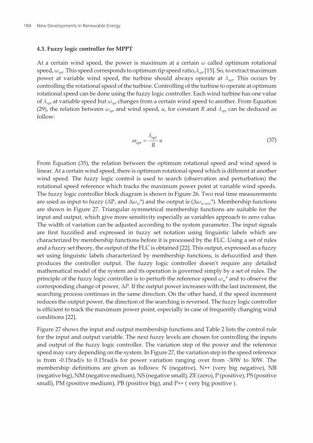
4.3. Fuzzy logic controller for MPPT
At a certain wind speed, the power is maximum at a certain ω called optimum rotationalspeed, ωopt. This speed corresponds to optimum tip speed ratio,λopt [15]. So, to extract maximumpower at variable wind speed, the turbine should always operate at λopt. This occurs bycontrolling the rotational speed of the turbine. Controlling of the turbine to operate at optimumrotational speed can be done using the fuzzy logic controller. Each wind turbine has one valueof λopt at variable speed but ωopt changes from a certain wind speed to another. From Equation(29), the relation between ωopt and wind speed, u, for constant R and λopt can be deduced asfollow:
optopt u
Rl
w = (37)
From Equation (35), the relation between the optimum rotational speed and wind speed islinear. At a certain wind speed, there is optimum rotational speed which is different at anotherwind speed. The fuzzy logic control is used to search (observation and perturbation) therotational speed reference which tracks the maximum power point at variable wind speeds.The fuzzy logic controller block diagram is shown in Figure 26. Two real time measurementsare used as input to fuzzy (ΔP, and Δωm*) and the output is (Δωm-new*). Membership functionsare shown in Figure 27. Triangular symmetrical membership functions are suitable for theinput and output, which give more sensitivity especially as variables approach to zero value.The width of variation can be adjusted according to the system parameter. The input signalsare first fuzzified and expressed in fuzzy set notation using linguistic labels which arecharacterized by membership functions before it is processed by the FLC. Using a set of rulesand a fuzzy set theory, the output of the FLC is obtained [22]. This output, expressed as a fuzzyset using linguistic labels characterized by membership functions, is defuzzified and thenproduces the controller output. The fuzzy logic controller doesn't require any detailedmathematical model of the system and its operation is governed simply by a set of rules. Theprinciple of the fuzzy logic controller is to perturb the reference speed ωm* and to observe thecorresponding change of power, ΔP. If the output power increases with the last increment, thesearching process continues in the same direction. On the other hand, if the speed incrementreduces the output power, the direction of the searching is reversed. The fuzzy logic controlleris efficient to track the maximum power point, especially in case of frequently changing windconditions [22].
Figure 27 shows the input and output membership functions and Table 2 lists the control rulefor the input and output variable. The next fuzzy levels are chosen for controlling the inputsand output of the fuzzy logic controller. The variation step of the power and the referencespeed may vary depending on the system. In Figure 27, the variation step in the speed referenceis from -0.15rad/s to 0.15rad/s for power variation ranging over from -30W to 30W. Themembership definitions are given as follows: N (negative), N++ (very big negative), NB(negative big), NM (negative medium), NS (negative small), ZE (zero), P (positive), PS (positivesmall), PM (positive medium), PB (positive big), and P++ ( very big positive ).
New Developments in Renewable Energy184

Time delay
FuzzyLogic
Controller
ωm*
Time delay
P
ωm-new*Δωm-new*
Time delay
Δωm*
ΔP
Figure 26. Input and output of fuzzy controller.
-30 30
N++ NB NM NS ZE PS PM PB P++
-0.15 0.15
N++ NB NM NS ZE PS PM PB P++
ZE PN
-0.15 0.15
Input membership functions
Output membership functions
Figure 27. Membership functions of fuzzy logic controller
Maximum Power Extraction from Utility-Interfaced Wind Turbineshttp://dx.doi.org/10.5772/54675
185

ΔP
Δωm
N++ NB NM NS ZE PS PM PB P++
N P++ PB PM PS ZE NS NM NB N++
ZE NB NM NS NS ZE PS PM PM PB
P N++ NB NM NS ZE PM PM PB PB
Table 2. Rules of fuzzy logic controller
4.4. Control of the grid side converter
The power flow of the grid-side converter is controlled in order to maintain the dc-link voltageat reference value, 600v. Since increasing the output power than the input power to dc-linkcapacitor causes a decrease of the dc-link voltage and vise versa, the output power will beregulated to keep dc-link voltage approximately constant. To maintain the dc-link voltageconstant and to ensure the reactive power flowing into the grid, the grid side converter currentsare controlled using the d-q vector control approach. The dc-link voltage is controlled to thedesired value by using a PI-controller and the change in the dc-link voltage represents a changein the q-axis (iqs) current component. Figure 28 shows a control block diagram of the grid sideconverter.
The active power can be defined as;
( )32s ds ds qs qsP v i v i= + (38)
The reactive power can be defined as:
( )32s qs ds ds qsQ v i v i= - (39)
By aligning the q-axis of the reference frame along with the grid voltage position vds=0 and vqs=constant because the grid voltage is assumed to be constant. Then the active and reactive powercan be obtained from the following equations:
32s qs qsP v i= (40)
32s qs dsQ v i= (41)
New Developments in Renewable Energy186

2
PWMconverter
vdc
PMSG
Speed control
abc / α, βClark’s
Trasformation
ωm* ωm
iα* iβ*
CCβ
iα iβ
vαs* vβs*
SVPWM
CCβ: β- axis current controllerCCα: α- axis current controller
CCα
ia ib ic
FLCΔP
iα iβ
Δωm
Figure 24. Control block diagram of generator side converter.
VC
a b c
q d
vdc*
iq* id*
CCq CCd iq id
vq* vd*
SVPWM
PWMconverter
vdc
vdc
ia ib
Utility
ic
θ
idCCq : q- axis Current ControllerCCd : d- axis Current Controller
VC : Voltage Controller
iq
Figure 28. Control block diagram of grid-side converter. Figure 28. Control block diagram of grid-side converter.
4.5. Simulation results
A co-simulation (PSIM/Simulink) program has been used where PSIM contains the powercircuit of the WECS and Matlab/Simulink has the whole control system as described before.The model of WECS in PSIM contains the WT connected to the utility grid through back–to-back bidirectional PWM converter. The control of whole system in Simulink contains thegenerator side controller and the grid side controller. The wind turbine characteristics and theparameters of the PMSG are listed in Appendix. The generator can be directly controlled bythe generator side controller to track the maximum power available from the WT. The windspeed is variable and changes from 7 m/s to 13 m/s as input to WT. To extract maximum powerat variable wind speed, the turbine should always operate at λopt. This occurs by controllingthe rotational speed of the WT. So, it always operates at the optimum rotational speed. ωopt
changes from a certain wind speed to another. The fuzzy logic controller is used to search theoptimum rotational speed which tracks the maximum power point at variable wind speeds.Figure 29 (a) shows the variation of the wind speed which varies randomly from 7 m/s to13m/s. On the other hand, Figure 29 (b) shows the variation of the actual and reference rotationalspeed as a result of the wind speed variation. At a certain wind speed, the actual and referencerotational speed have been estimated and this agree with the power characteristic of the windturbine shown later in Figure 23. I.e. the WT always operates at the optimum rotational speedwhich is found using FLC; hence, the power extraction from wind is maximum at variable
Maximum Power Extraction from Utility-Interfaced Wind Turbineshttp://dx.doi.org/10.5772/54675
187

wind speed. It is seen that according to the wind speed variation the generator speed variesand that its output power is produced corresponding to the wind speed variation. The fuzzylogic controller works well and it gives the good tracking performance for the maximumoutput power point. The fuzzy logic controller makes WT always operates at the optimumrotational speed. On the other hand, the grid-side controller maintains the dc-link voltage atthe desired value, 600v, as shown in Figure 29 (c). The dc-link voltage is regulated by exportingactive power to the grid as shown in Figure 29 (d). The reactive power transmitted to the gridis shown in Figure 29 (e).
3
(a)
(b)
(c)
(d)
(e)
Figure 29. Different simulation waveforms: (a) Wind speed variation (7-13) m/s. (b) Actual and reference rotationalspeed (rad/s). (c) dc-link voltage (v). (d) Active power (watt). (e) Reactive power (Var).
New Developments in Renewable Energy188
5. Conclusions
Wind energy conversion system has high priority among the various renewable energysystems. Maximum power extraction from wind energy system became an important researchtopic due to the increase in output energy by using this technique. Wind speed sensorlessMPPT control has been a very active area of research. In this study, a concise review of MPPTcontrol methods has been presented for controlling WECS. On the other hand, there is acontinuing effort to make converter and control schemes more efficient and cost effective inhopes of developing an economically viable solution of increasing environmental issues.Wind power generation has grown at a high rate in the past decade and will continue withpower electronic technology advanced. The survey of MPPT algorithms have been classi‐fied into MPPT algorithms with wind speed sensor and MPPT algorithms without windspeed sensor. A co-simulation (PSIM/Simulink) program has been proposed for WECS wherePSIM contains the power circuit of the WECS and Matlab/Simulink has the control circuit ofthe system. The WT is connected to the grid via back–to-back PWM-VSC. The generator sidecontroller and the grid side controller have been done in Simulink. The main function of thegenerator side controller is to track the maximum power from wind through controlling therotational speed of the turbine using fuzzy logic controller. The fuzzy logic algorithm for themaximum output power of the grid-connected wind power generation system using a PMSGhas been proposed and implemented above. The PMSG was controlled in indirect-vectorfield oriented control method and its speed reference was determined using fuzzy logiccontroller. The grid-side converter controls the dc-link voltage at a desired value, 600V, forthe proposed system. Active and reactive power control has been achieved by controlling q-axis and d-axis grid current components respectively. The d-axis grid current is controlledto be zero for unity power factor and the q-axis grid current is controlled to deliver the powerflowing from the dc-link to the grid. The simulation results prove the superiority of FLC andthe whole control system.
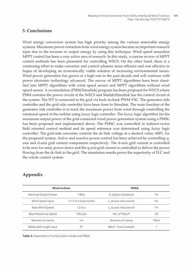
Appendix
Wind turbine PMSG
Nominal Output Power 19kw Rs (stator resistance) 1m
Wind speed input 7:13 m/s (saw tooth) Ld (d-axis inductance) 1m
Base Wind Speed 12 m/s Lq (q-axis inductance) 1m
Base Rotational Speed 190 rpm No. of Poles P 30
Moment of inertia 1m Moment of inertia 100m
Blade pitch angle input 0º Mech. Time Constant 1
Table 3. Parameters of wind turbine model and PMSG
Maximum Power Extraction from Utility-Interfaced Wind Turbineshttp://dx.doi.org/10.5772/54675
189

Acknowledgements
The authors acknowledge the National Plan for sciences and Technology program (Project No.:ENE226-02-08) by King Saud University for the financial support to carry out the researchwork reported in this chapter.
Author details
Ali M. Eltamaly, A. I. Alolah and Hassan M. Farh
Department of Electrical Engineering, College of Engineering, King Saud University,Riyadh, Saudi Arabia
References
[1] Vahid, O, & Hassan, N. Maximum power extraction for a wind-turbine generator withno wind speed sensor. in Proc. on IEEE, Conversion and Delivery of Electrical Energyin the 21st Cen. (2008). , 1-6.
[2] Thomas, A, & Lennart, S. An overview of wind energy status (2002). Renewable andsustainable energy reviews 2002, 6:67-128.
[3] DuboisOptimized permanent magnet generator topologies for direct-drive windturbines. Ph.D. dissertation, Delft Univ. Technol., Delft, The Netherlands; (2004).
[4] Anders, G. Design of direct-driven permanent-magnet generators for wind turbines.Ph.D. dissertation, Chalmers Univ. Technol., Goteborg, Sweden; (1996).
[5] Torbjörn, T, & Jan, L. Control by variable rotor speed of a fixed pitch wind turbineoperating in a wide speed range. IEEE Trans. on Energy Conversion, EC-8, (1993). ,520-526.
[6] BuehringFreris. Control policies for wind energy Conversion System. Proc. Inst. Elect.Eng. C, (1981). , 128, 253-261.
[7] Erimis, H. B, Ertan, E, & Akpinar, F. Ulgut, Autonomous wind energy conversionsystems with a simple controller for maximum power transfer, Proc. Inst. Elect. Eng.B, (1992). , 139, 421-428.
[8] ChedidMrad, Basma. Intelligent control of a class of wind energy conversion systems.IEEE Trans. on Energy Conversion, EC-14, (1999). , 1597-1604.
[9] Marcelo, S, Bimal, B, & Ronald, S. Fuzzy logic-based intelligent control of a variablespeed cage machine wind generation system. IEEE Trans. on Power Electron., PE-12,(1997). , 87-94.
New Developments in Renewable Energy190

[10] EnslinWyk. A study of a wind power converter with micro-computer based maximumpower control utilizing an over- synchronous electronic Scherbius cascade. RenewableEnergy World (1993). , 2(6), 551-562.
[11] Quincy, W, & Liuchen, C. An intelligent maximum power extraction algorithm forinverter-based variable speed wind turbine systems. IEEE Transactions on PowerElectronics (2004). , 19(5), 1242-1249.
[12] Quincy, W. Maximum wind energy extraction strategies using power electronicconverters. PhD. dissertation, Univ. of New Brunswick, Canada, (2003).
[13] Hui, L, Shi, K. L, & Mclaren, P. G. Neural-network-based sensorless maximum windenergy capture with compensated power coefficient. IEEE Trans. Ind. Appl., (2005). ,41(6), 1548-1556.
[14] RajuFernandes, Chatterjee. A UPF power conditioner with maximum power pointtracker for grid connected variable speed wind energy conversion system. Proc. of 1stInt. Conf. on PESA, Bombay, India, (2004). , 107-112.
[15] Majid, A. A, Yatim, A. H. M, & Chee, W. Tan. A Study of Maximum Power PointTracking Algorithms for Wind Energy System. Proc. of 1st IEEE Conf. on Clean Energyand Technology CET, (2011). , 321-326.
[16] Mónica, C, Santiago, A, & Juan, C. B. Control of Permanent-Magnet Generators Appliedto Variable-Speed Wind-Energy Systems Connected to the Grid. IEEE Trans. EnergyConversion, 21 March (2006). , 130-135.
[17] Seung-ho, S, Shin-il, K, & Nyeon-kun, H. Implementation and control of grid connectedAC-DC-AC power converter for variable speed wind energy conversion system. IEEE,(2003). , 154-158.
[18] Ali, M. E. Modelling of wind turbine driving permanent Magnet Generator withmaximum power point tracking system. J. King Saud Univ., Riyadh,(2007). , 19(2),223-237.
[19] Mahmoud, M. H, Mohamed, O, Mahrous, E. A, & Mahmoud, A. S. Simple sensorlesscontrol technique of permanent magnet synchronous generator wind turbine. Proc. ofIEEE Int. Conf. on Power and Energy,PEC201),Kuala Lumpur, Malaysia, (2010). ,512-517.
[20] Swagat, P, Mohanty, K. B, & Benudhar, S. Performance Comparison of a Robust SelfTuned Fuzzy Logic Controller used for Power Control in Wind Conversion Systems.Proc. of Modern Electric Power Systems, MEPS’10, Wroclaw, Poland, September(2010). , 20-22.
[21] Xingjia, Y, Changchun, G, Zuoxia, X, Yan, L, & Shu, L. Variable Speed Wind TurbineMaximum Power Extraction Based on Fuzzy Logic Control. Proc. of Int. Conf. onIntelligent Human-Machine Systems and Cybernetics, IEEE; (2009). , 202-205.
Maximum Power Extraction from Utility-Interfaced Wind Turbineshttp://dx.doi.org/10.5772/54675
191

[22] Ahmed, G. A, Dong-choon, L, & Jul-ki, S. Variable speed wind power generation systembased on fuzzy logic control for maximum power output tracking. in Proc. 35th AnnualIEEE Power Electron. Specialists Conf., PESC, Aachen, Germany, (2004). , 3, 2039-2043.
[23] Tanaka, T, & Toumiya, T. Output control by hill-climbing method for a small scale windpower generating system. Renewable Energy, (1997). , 12(4), 387-400.
[24] Tan, K, & Islam, S. Optimum control strategies in energy conversion of PMSG windturbine system without mechanical sensors. IEEE Trans., (2004). , EC-19, 392-399.
[25] Datta, R, & Ranganathan, V. T. A method of tracking the peak power points for avariable speed wind energy conversion system. IEEE Trans. on Energy Conversion,March (2003). , EC-18, 163-168.
[26] Brendan, F, Damian, F, Leslie, B, Nick, J, David, M, Mark, O, Richard, W, & Olimpo, A.Wind power integration: connection and system operational aspects. Proc. IET Powerand Energy Series, (2007). , 50, 77-85.
[27] Siegfried, H. Grid Integration of Wind Energy Conversion Systems. John Wiley & Sons,Germany; (2006).
[28] Gary, L. J. Wind Energy Systems. Prentice Hall, Englewood cliffs; (2003).
[29] Peter, V. Sensorless Vector and Direct Torque Control. Oxford science publica‐tions,New York, (1998).
[30] Orlando, M, Liserre, V. G, & Monopoli, A. Dell’Aquila. Speed Sensorless Control of aPMSG for Small Wind Turbine Systems. Proc. of IEEE International SymposiumonIndustrial Electronics, ISlE, Seoul, Korea, July (2009). , 5-8.
New Developments in Renewable Energy192