Embed Size (px)
Citation preview
Revision date: 18/10/2020 Revision number: 1.1
Mauritius Amateur Radio RA23 (Class A)
Student Reference Booklet
To be used by the student for a study reference

Introduction
This document details the subjects tested under the ICTA RA23 (Class A) exam syllabus. You, as the
student, will be able to utilise this document as a study guide for this examination.
You will see in this document tables which contain the syllabus section details in the left hand column
and in the right hand column, references to where you will find some resources for covering the syllabus
sections.
The header of the table also states how many questions and what question numbers these syllabus
sections will appear in the actual exam.
Note: You can see this example shows a total of 9 questions and will be questions 1 to 9 in the exam.
This document will be updated by M.A.R.S when new resources become available or should the exam
syllabus be updated.
Exam
The RA23 exam will comprised of 60 multiple choice questions, with a period of 2 hours to complete
the exam. A sample paper is available from the M.A.R.S.

Licensing Conditions (9 Q) (Exam question numbers 1-9)
Syllabus Notes for Candidates
ITU Radio Regulations relating to:
purpose of the amateur
service
emission
designations
permitted communications
use of call signs
secondary allocations
National Regulations, in particular “Wireless Telegraphy (Amateur Station Licence)
Licence Conditions published by ICTA
In relation to the Amateur Station Operational Bands/Powers/Modes
Permitted in ICTA licence conditions the
syllabus requirements include;
Permitted frequencies,
Permitted modes, maximum power
levels (including power levels for land
mobile and maritime mobile.
Status of allocation (primary / secondary)
Entitlement to operate maritime mobile
“CEPT Amateur Radio Licence” regulations regarding operation during visits to other countries participating in these arrangements
As well as permitted frequencies etc., note
the other requirements set out in ICTA and
other documents referred to in the syllabus:
SWR and frequency measuring
devices
Log book entries
Limitations / requirements for land mobile and maritime mobile operation
Limits on non-ionising radiation and spurious emissions: it is not necessary to memorise the quantitative limits, however the aims of the limits should be understood
For the CEPT amateur radio licence regulations, see “CEPT Recommendation T/R 61-01 (CEPT licences)” which is available at https://docdb.cept.org/download/e4b9c459-5726/TR61-02.pdf Students should also use their Licence conditions provided by the ICTA for licence conditions.

Operating Rules and Procedures (8 Q) (Exam question numbers 10-
17)
Syllabus Notes for Candidates
ITU Radio Regulations relating to the composition of call signs
ITU radio regions
National call sign prefixes [Europe and North America] – see Annex 1
IARU band plans for frequencies up to 440 MHz
Distress signals, emergency traffic and natural disaster communication
Format of CQ calls to specific stations
Q-codes – see Annex 1
Operational abbreviations – see Annex 1
Phonetic alphabet – see Annex 1
RST code – see Annex 1
See ANNEX 1
In reviewing the band plans, note in
particular the band segments for:
CW only
contest preferred
priority for
intercontinental
beacons only
global emergency centre of
activity
Also note the accepted usage in the bands for USB and LSB.

Electrical and Electronic Principles including Components and
Circuits (10Q) (Exam question numbers 18-27)
Syllabus Notes for Candidates
DC, Resistors and Ohm’s Law
Meaning of the terms voltage, current, resistance and power, the units used to measure them and the relationship between them
Ohm’s Law and its various formulations
Symbols used for the units (V, I, R, W, Ÿ, kŸ, MŸ etc.)
Resistors in series and in parallel, including a combination of series and parallel resistors – current, voltage and power in these circuits
Resistor accuracy and its impact on voltage, current and power
Power dissipation
Conductors, semi-conductors and insulators
A knowledge of Ohm’s Law is essential.
Ohms law online
Ohms law video
While simple maths may be needed to answer some questions, the “intuitive understanding” is just as important as mathematical ability.
Ohms law online (2)
Note that resistors determine both the current flow and the voltage drop. As well as the links above students can use the two books produced by the Radio Society of Great Britain ISBN: 9 781910 193617 ISBN: 9 781910 193624
Inductors
Units (µH, mH etc.) and symbols
Calculations involving series and parallel inductors
The effect of number of turns, diameter, length and core material on inductance (qualitative treatment only)
Inductance and inductive reactance
Impedance
Only a general understanding of the effect on inductance of different physical characteristics (number of turns etc.) of inductors is expected.
Inductance Online Inductance Online (2) Inductance Video Inductance Video (2) As well as the links above students can use the two books produced by the Radio Society of Great Britain ISBN: 9 781910 193617 ISBN: 9 781910 193624
Capacitors
Units (µF, pF etc.) and symbols
Calculations involving series and parallel capacitors
The relationship between dimensions, capacitance and dielectric (qualitative treatment only)
Capacitance and capacitive reactance
See the comment on inductors in relation to reactance.
Capacitors Video Capacitors Online Capacitors Online (2)

Impedance, Resonance and Reactance
Meaning of impedance, resonance and reactance
Calculation of impedance of an inductor from resistance and reactance
How reactance of an inductor and a capacitor varies with frequency
Parallel and series resonant circuits Q-factor
These topics are in effect an extension of the sections on inductors and capacitors.
IRR Online Impedance Video Online Impedance Video Online (2) Impedance Video Online (3) Inductive Reactance Video Online Capacitive Reactance Video Online

Electrical and Electronic Principles including Components and
Circuits (cont’d)
Syllabus Notes for Candidates
Other Components
Diodes: silicon, zener, LED and varicap
Transistors: NPN, PNP, FET
Transformers: isolation, step-up, step-down; turns ratio, current ratio and voltage ratio
Quartz crystals
Batteries
Component symbols
An understanding of the purpose and the behaviour (e.g. rectification, Peak Inverse Voltage (PIV), voltage drop, amplification) of these components is required.
Video 1 Video 2
Circuits
Circuits and output waveforms of full-wave, halfwave and bridge rectifier power supplies, including smoothing and voltage regulation
Recognise common-emitter, commoncollector/emitter-follower, common-base circuits
Class A, B, A/B and C biasing
Candidates need to be generally familiar with what these simple circuits look like and their principal characteristics.
In relation to biasing circuits, the key differences between the various types are in efficiency and harmonic output. Video 1
Alternating Current
The unit (hertz), frequency, period, duration of period and amplitude
Sine waves and square waves
Ohm’s Law in inductors and capacitors
Relationship between peak, peak-to-peak, average and RMS value of sine waves
Harmonics
Phase, phase difference, phase lag and lead
A good general understanding of what is involved in alternating current (AC) is needed.
Candidates should understand what a graphic representation of AC in time would look like.
An understanding of how reactance is dealt with is required.
A basic understanding of phasing concepts is all that is required. Video 1
Miscellaneous
Amplifier gains, expressed in dB, for the following values: 0dB, 3dB, 6dB, 10dB and 20dB [both positive and negative]
Digital Signal Processing (DSP):
xpurpose / benefits xbasic
block diagram ximportance
of sampling rate
LC (i.e. coil/capacitor) oscillators and crystal oscillators
Candidates should be aware that DSP is used to filter noise and audio in receivers and to synthesize signals in transmitters.
Candidates should be able to recognise LC and crystal oscillator circuits and be aware of the typical usage, advantages and disadvantages of each type.

Transmitters and Receivers (7Q)(Exam question numbers 28-34)
Syllabus Notes for Candidates
Transmitters (modes: CW, SSB, AM, FM)
Generic HF station and transmitters for each mode: block diagrams and principal function of each stage
Content of transmitted signals for each mode and implications for power amplifier duty cycle and rating
Effect of audio modulation, where applicable
Typical RF bandwidth of signals in each mode
Methods of achieving frequency stability
FM: modulation index, deviation, calculating total bandwidth
Amplifiers including linear amplifiers and their uses
Calculation of ERP (dBW) from output power (Watts), antenna gain (dB), feeder loss (dB)
Purpose of ALC
Output impedance
It is important to understand both the function and position (within the block diagram) of stages such as the variable frequency oscillator (VFO), buffer, driver, amplifier, balanced modulator, crystal filter, mixer, frequency multiplier, SWR meter, low pass filter, dummy load.
Note that the desired transmitting frequency is often produced by mixing together the output from two or more frequency sources, and how unwanted frequencies may be produced.
A broad understanding is needed of the nature of the output signal from CW, SSB, AM and FM transmissions. Note also that the modulating signal may be analogue or digital; in the case of digital signals which are continuous, note the particular need to be conscious of drive levels and transmitter ratings.
A broad understanding is needed of the function and operation of linear amplifiers (including valve amplifiers).
Candidates need to understand that some transmitters and most amplifiers use valves, which may have voltages in excess of 1kV applied (note the “high voltages” reference in Syllabus Section A.4 Safety)
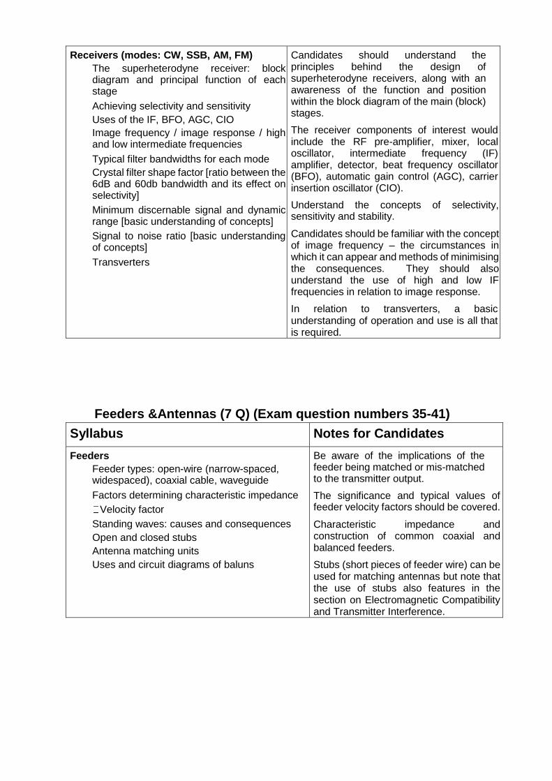
Receivers (modes: CW, SSB, AM, FM)
The superheterodyne receiver: block diagram and principal function of each stage
Achieving selectivity and sensitivity
Uses of the IF, BFO, AGC, CIO
Image frequency / image response / high and low intermediate frequencies
Typical filter bandwidths for each mode
Crystal filter shape factor [ratio between the 6dB and 60db bandwidth and its effect on selectivity]
Minimum discernable signal and dynamic range [basic understanding of concepts]
Signal to noise ratio [basic understanding of concepts]
Transverters
Candidates should understand the principles behind the design of superheterodyne receivers, along with an awareness of the function and position within the block diagram of the main (block) stages.
The receiver components of interest would include the RF pre-amplifier, mixer, local oscillator, intermediate frequency (IF) amplifier, detector, beat frequency oscillator (BFO), automatic gain control (AGC), carrier insertion oscillator (CIO).
Understand the concepts of selectivity, sensitivity and stability.
Candidates should be familiar with the concept of image frequency – the circumstances in which it can appear and methods of minimising the consequences. They should also understand the use of high and low IF frequencies in relation to image response.
In relation to transverters, a basic understanding of operation and use is all that is required.
Feeders &Antennas (7 Q) (Exam question numbers 35-41)
Syllabus Notes for Candidates
Feeders
Feeder types: open-wire (narrow-spaced, widespaced), coaxial cable, waveguide
Factors determining characteristic impedance
Velocity factor
Standing waves: causes and consequences
Open and closed stubs
Antenna matching units
Uses and circuit diagrams of baluns
Be aware of the implications of the feeder being matched or mis-matched to the transmitter output.
The significance and typical values of feeder velocity factors should be covered.
Characteristic impedance and construction of common coaxial and balanced feeders.
Stubs (short pieces of feeder wire) can be used for matching antennas but note that the use of stubs also features in the section on Electromagnetic Compatibility and Transmitter Interference.

Antennas
Antenna types: half-wave, quarter-wave vertical (ground plane), folded dipole, trap dipole, Yagi
Physical construction (dimensions, components)
Balanced and unbalanced antennas
Distribution of current and voltage
Impedance at the feed point
Capacitive or inductive reactance of a non-resonant antenna
Polarisation, directivity, efficiency and gain
Effective radiated power (ERP)
Front to back ratio
Horizontal and vertical radiation pattern
Relationship between frequency and wavelength
In order to answer questions on
antennas, for each antenna type,
candidates should be familiar with
(where relevant) – what the antenna
looks like
typical dimensions relative to operating frequency
characteristic impedance
effect of shortening or lengthening the antenna
name and positioning of the parasitic elements
how traps are constructed and their effect
voltage and current
patterns radiation
patterns
Also understand the concepts of ‘balanced’ and ‘unbalanced’ in relation to antennas and be aware of examples of each type.

Electromagnetic Compatibility and Transmitter Interference (6Q)
(Exam questions 42-47)
Syllabus Notes for Candidates
Interference in electronic equipment
Aims of Electromagnetic Compatibility (EMC)
Electromagnetic Compatibility is the avoidance of interference between two pieces of electronic equipment.
Cause of interference in electronic equipment
Field strength of the transmitter Spurious
radiation from the transmitter Undesired
influence on the equipment:
via the antenna
input
via other
connected lines
by direct radiation
Cross modulation and intermodulation
Over modulation, splatter, key clicks
Overdriving linear amplifiers
Spurious radiation from a transmitter could include parasitic radiation, harmonics, unwanted mixer products, splatter, key clicks and spurious emissions.
Note that the reasons for receiver interference
may include –
lack of selectivity
interference received through the mains power supply
feeder problems
Understand bandwidth in relation to interference. Contained within the RSGB Intermediate and Full licence books.
Measures against interference
Measures to prevent and eliminate interference effects:
Filtering
Decoupling
Shielding
Location of antennas
Balanced antenna systems and antenna tuning units
Drive levels in linear amplifiers
Operating frequency – ensuring that no part of a transmitted signal is outside band limits [respective implications for USB and LSB transmissions]
Candidates should be familiar with typical filter circuits – low pass, high pass, band pass and band reject – as well as their uses.
Measure against interference would include the use of coaxial stubs and toroids.
In relation to linear amplifiers, note the importance of correct drive levels and understand the consequences of incorrect drive levels.

Propagation (6 Q) (Exam question numbers 48-53)
Syllabus Notes for Candidates
Electromagnetic waves – polarisation
Atmospheric regions: troposphere, ionosphere
For the troposphere and individual ionospheric layers: location, influence of the sun, effect on propagation at different frequencies
Solar flares / sunspot cycles
Critical frequency & maximum usable frequency (MUF)
Modes of propagation: ground wave, sky wave (ionospheric wave), tropospheric wave, ducting, refraction, diffraction
Angle of radiation and skip distance
The influence of the height of antennas on the distance that can be covered
Meteor scatter, reflections from the moon
Sporadic E propagation
Impact of distance on field strength for line of sight propagation
Fading
When studying atmospheric regions, consider their effects on LF / HF / VHF propagation, respectively (where and at what times of the day / year are they typically situated, do they absorb or reflect? etc.). Be aware also of typical ranges for single-hop transmissions using the different layers.
As regards field strength for line of sight propagation, note that there are two methods of expressing RF field strengths:
Watts per square metre (W/m²), i.e. “power density”. The power density is proportional to the inverse of the square of the distance from the source (e.g. at twice the distance you get a quarter of the power in W/m²)
Volts per metre (V/m). Using this measurement, the power is proportional simply to the inverse of the distance from the source (e.g. at twice the distance you get half the power in V/m)
In relation to fading, a basic understanding of how it occurs is all that is required.
Measurements (3 questions) (Exam question numbers 53-56)
Syllabus Notes for Candidates
Making Measurements
Measurement of DC and AC (including RF) voltage, current, resistance and power
Ammeter and voltmeter: usage, internal resistance and how to extend their ranges
Transmitter measurements: RF voltage, current and power, PEP (two-tone test), signal quality, spurious signals
DC input power / RF output power / efficiency
Usage and placement of an SWR meter
Resonant frequency of a tuned circuit
Impact of antenna gain and feeder loss on ERP
Because radio amateurs can build and set up their own equipment, they are obliged to be in a position to ensure that their equipment is operated within the permitted frequency bands, at permitted power levels and with appropriate signal quality etc. The ability to use suitable measuring equipment arises from this obligation.
Know the efficiency of different classes of amplifiers.

Measuring Instruments
Analogue and digital meters
RF power meter, RMS voltmeter
SWR meter
Frequency measurement instruments
Oscilloscope
Dummy load: usage and construction
Candidates need to know where different measuring instruments should be placed in circuits – whether in series or in parallel with the current flow, at the circuit input or output etc.
In relation to an oscilloscope, note in particular what is shown on the X and Y axis, respectively.
Safety (4 Q) (Exam question numbers 57-60)
Syllabus Notes for Candidates
The human body – electric shock risks and
dealing with the consequences of an electric
shock
dangers of exposure to electromagnetic radiation, including hazards from antennas and waveguides
safe working conditions Minimising risks from the mains power supply, including:
the correct wiring of mains plugs
fuses and appropriate fuse ratings
isolating transformers
correct earthing procedure
use of trip switches such as Residual Current
Devices (RCDs) or Earth Leakage Circuit Breakers (ELCBs)
Additional precautions needed where high voltages are present
Lightning protection Location of antennas
Non-ionising radiation:
Sources
Health Risks
Methods of minimising adverse effects
Note that there is a regulatory requirement for radio amateurs to ensure that “…the safety of persons or property is not endangered …”
Safe working conditions would
include when soldering, the
requirement for good
ventilation and suitable eye
protection
use of secure positioning when
drilling, sawing or filing
In relation to high voltages,
note – the use of bleeder
resistors and the discharge
of smoothing capacitors
valves used in transmitters /
amplifiers may have
voltages in excess of 1kV
access needs to be strictly
controlled
tools used to measure high
voltages should be checked
regularly
In relation to the location of
antennas and feeders, the
issues would include keeping
non-ionising radiation within
permitted limits
protecting against damage to persons or property
guarding against RF burns position of overhead power
lines

Revision date: 18/10/2020 Revision number: 1.1
ANNEX 1
Principal national call sign prefixes
PREFIX COUNTRY
DL GERMANY
EA SPAIN
EI IRELAND (REPUBLIC OF)
F FRANCE
GM SCOTLAND
JA JAPAN
ON BELGIUM
PA NETHERLANDS
PY BRAZIL
W,K USA
ZS SOUTH AFRICA
3B8 MAURITIUS
FR REUNION
5R8 MADAGASCAR
S79 SEYCHELLES
Note: Many other call sign prefixes are allocated to these countries and entities, however
those listed here are the prefixes which exam candidates should be familiar with.

Q - CODES Code Question Answer
QRK What is the readability of my signals? The readability of your signals is ...
QRM Are you being interfered with? I am being interfered with
QRN Are you troubled by static? I am troubled by static
QRO Shall I increase transmitter power? Increase transmitter power
QRP Shall I decrease transmitter power? Decrease transmitter power
QRT Shall I stop sending? Stop sending
QRZ Who is calling me? You are being called by ...
QRV Are you ready? I am ready
QSB Are my signals fading? Your signals are fading
QSL Can you acknowledge receipt? I am acknowledging receipt
QSO Can you communicate with ... direct? I can communicate ... direct
QSY Shall I change to transmission on another
frequency? Change transmission to another frequency
QRX When will you call again? I will call you again at ... hours on ... kHz (or MHz)
QTH What is your position in latitude and
longitude (or according to any other
indication)?
My position is ... latitude, ... longitude (or
according to any other indication)
Abbreviations
BK Signal used to interrupt a transmission in progress
CQ General call to all stations
CW Continuous wave
DE From, used to separate the call sign of the station called from that of the calling station
K Invitation to transmit
MSG Message
PSE Please
RST Readability, signal-strength, tone-report
R Received
RX Receiver
TX Transmitter
UR Your

Phonetic Alphabet A = Alpha
B = Bravo
C = Charlie
D = Delta
E = Echo
F = Foxtrot
G = Golf
H = Hotel
I = India
J = Juliet
K = Kilo
L = Lima
M = Mike
N = November
O = Oscar
P = Papa
Q = Quebec
R = Romeo
S = Sierra
T = Tango
U = Uniform
V = Victor
W = Whiskey
X = X-ray
Y = Yankee
Z = Zulu
RST Code Readability
R1 Unreadable
R2 Barely readable, occasional words distinguishable
R3 Readable with considerable difficulty
R4 Readable with practically no difficulty
R5 Perfectly readable
Signal Strength S1 Faint signal, barely perceptible
S2 Very weak
S3 Weak
S4 Fair
S5 Fairly good
S6 Good
S7 Moderately strong
S8 Strong
S9 Tone
Very strong signals
T1 Extremely rough hissing note
T2 Very rough AC note, no trace of musicality
T3 Rough AC. tone, rectified but not filtered
T4 Rough note, some trace of filtering
T5 Filtered rectified AC but strongly ripple-modulated
T6 Filtered tone, definite trace of ripple modulation
T7 Near pure tone, trace of ripple modulation
T8 Near perfect tone, slight trace of modulation
T9 Perfect tone, no trace of ripple or modulation of any kind

FORMULA SHEET PROVIDED DURING THE EXAM


![Amateur Operato Advanced - Australian Maritime College · Amateur Operato Advanced Syllabus and Examination. The Amateur Licence (amateur advanced station) [the Advanced Amateur Licence]](https://img.dokumen.tips/doc/110x75/5f072ed67e708231d41bb822/amateur-operato-advanced-australian-maritime-college-amateur-operato-advanced.jpg)