Embed Size (px)
Citation preview

1
SHREE GANPATI INSTITUTE OF TECHNOLOGY, GHAZIABAD
INPLANT TRAINING REPORT
Submitted by:-
Ankur singh (B.Tech - M.E.)
Instructor:Instructor:Instructor:Instructor:---- Chief Instructor:Chief Instructor:Chief Instructor:Chief Instructor:----
Mr. S.K. Sayyad Mr. C.R. Shetty
Conducted At:-
Central Railway Carriage Workshop, Matunga.
(Mumbai)
Year 2011-12
2
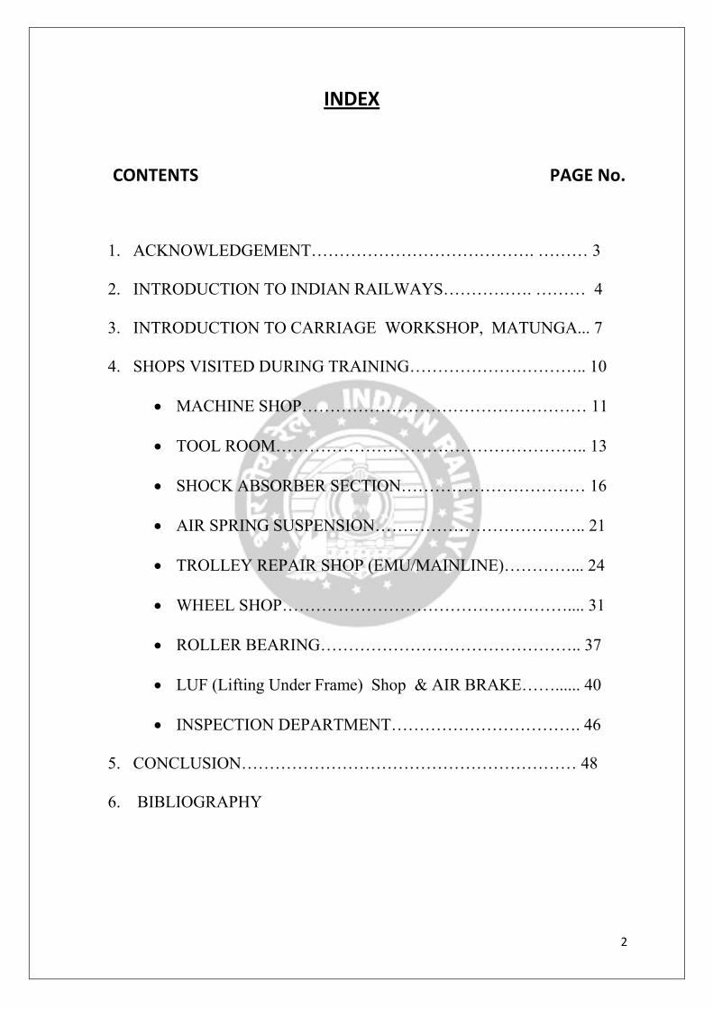
INDEX
CONTENTS PAGE No.
1. ACKNOWLEDGEMENT…………………………………. ……… 3
2. INTRODUCTION TO INDIAN RAILWAYS……………. ……… 4
3. INTRODUCTION TO CARRIAGE WORKSHOP, MATUNGA... 7
4. SHOPS VISITED DURING TRAINING………………………….. 10
• MACHINE SHOP…………………………………………… 11
• TOOL ROOM……………………………………………….. 13
• SHOCK ABSORBER SECTION…………………………… 16
• AIR SPRING SUSPENSION……………………………….. 21
• TROLLEY REPAIR SHOP (EMU/MAINLINE)…………... 24
• WHEEL SHOP…………………………………………….... 31
• ROLLER BEARING……………………………………….. 37
• LUF (Lifting Under Frame) Shop & AIR BRAKE……...... 40
• INSPECTION DEPARTMENT……………………………. 46
5. CONCLUSION…………………………………………………… 48
6. BIBLIOGRAPHY

3
ACKNOWLEDGEMENTACKNOWLEDGEMENTACKNOWLEDGEMENTACKNOWLEDGEMENT
� We would like to use this medium to express our sincere feelings of
gratitude to all those people who have selflessly taken pains to make this
report successful and our training at carriage workshop, central railway,
Matunga. It is very worthwhile and value added experience take this
opportunity to express our gratitude to all the individuals whose
contribution have helped us in undergoing training
� First of all we would like to thank Mr.A.R.Tupe (CWM), Mr.A.K.Gupta
(APLE/Training Officer) and Mr. C.R.Shetty (CI, BTC) for giving us an
opportunity to take training in this historic workshop.
� We express our heartily gratitude to Mr. S.K. Sayyad (Jr. Inst, BTC) for
his unstinting support and suggestions which gave us direction to work.
� We would also like to thank all workshop officials, shop superintendents,
working staff for the invaluable help at all the time.
------------------
INTRODUCTION TO INDIAN RAILWAYS :
� Indian Railways abbreviated as
owned railway company of
country's rail transport
the Government of India
� Railways were first introduced to India in 1853. By 1947, the year
of India's independence
systems were nationalised as one unit, becoming one of the largest
networks in the world. IR oper
systems on a multi-
also owns locomotive
� Indian Railways has more than 64,215 kilometres (39,901 mi)
and 7,083 stations. It has the world's fourth largest railway network after
those of theUnited States
length and breadth of the
and 2.8 million tons of
commercial or utility employers, with more than 1.6
As to rolling stock, IR owns over 230,000 (freight) wagons, 60,00
coaches and 9,000 locomotives
INTRODUCTIONINTRODUCTIONINTRODUCTIONINTRODUCTION
INTRODUCTION TO INDIAN RAILWAYS :-
abbreviated as IR is the central government
railway company of India, which owns and operates most of the
rail transport. It is overseen by the Ministry of Railways
Government of India.
Railways were first introduced to India in 1853. By 1947, the year
India's independence, there were forty-two rail systems. In 1951 the
systems were nationalised as one unit, becoming one of the largest
networks in the world. IR operates both long distance and suburban rail
-gauge network of broad, metre and narrow
locomotive and coach production facilities.
Indian Railways has more than 64,215 kilometres (39,901 mi)
stations. It has the world's fourth largest railway network after
United States, Russia and China. The railways traverse the
length and breadth of the country and carry over 30 million passengers
and 2.8 million tons of freight daily. It is one of the world's largest
commercial or utility employers, with more than 1.6 million employees.
, IR owns over 230,000 (freight) wagons, 60,00
coaches and 9,000 locomotives.
4
central government-
, which owns and operates most of the
Ministry of Railways of
Railways were first introduced to India in 1853. By 1947, the year
two rail systems. In 1951 the
systems were nationalised as one unit, becoming one of the largest
ates both long distance and suburban rail
narrow gauges. It
Indian Railways has more than 64,215 kilometres (39,901 mi) of track
stations. It has the world's fourth largest railway network after
The railways traverse the
country and carry over 30 million passengers
It is one of the world's largest
million employees.
, IR owns over 230,000 (freight) wagons, 60,000
5
Organizational structure:-
� Indian Railways is a department owned and controlled by
the Government of India, via the Ministry of Railways.
� As of May 2011, the Railway Ministry is headed by Manmohan Singh,
the Union Minister for Railways, and assisted by two ministers of State
for Railways.
� Indian Railways is administered by the Railway Board, which has a
financial commissioner, five members and a chairman.
� Indian Railways is divided into zones, which are further sub-divided into divisions. The number of zones in Indian Railways increased from six to
eight in 1951, nine in 1952, and finally 17 in 2010. Each zonal railway is
made up of a certain number of divisions, each having a divisional
headquarters. There are a total of sixty-seven divisions.
� The zones are further divided into divisions under the control of Divisional Railway Managers (DRM).
� Each of the seventeen zones, including Kolkata Metro, is headed by a
General Manager (GM) who reports directly to the Railway Board.
� The divisional officers of engineering, mechanical, electrical, signal and
telecommunication, accounts, personnel, operating, commercial and
safety branches report to the respective Divisional Manager and are in
charge of operation and maintenance of assets.
� Further down the hierarchy tree are the Station Masters who control
individual stations and the train movement through the track territory
under their stations' administration.
� As of 31 March 2011, 21,014 km of the total 64,215 km route length is
electrified. Since 1960, almost all electrified sections on IR use
25,000 V AC traction through overhead catenary delivery. A major
exception is the entire Mumbai section, which uses 1,500 V DC. and is
currently undergoing change to the 25,000 V AC system. Another
exception is the Kolkata Metro, which uses 750 V DC delivered through
a third rail.
� Indian railways uses four gauges, the 1,676 mm (5 ft 6 in) broad
gauge which is wider than the 1,435 mm (4 ft 8 1⁄2 in) standard gauge;
the 1,000 mm (3 ft 3 3⁄8 in) metre gauge; and two narrow
gauges,762 mm (2 ft 6 in) and 610 mm (2 ft) . Track sections are rated for
speeds ranging from 75 to 160 km/h (47 to 99 mph).
6
� Motto :-
� To provide safe and fast transportation of passengers and freight.
� As with most developing economies, the main reason for this was the
policy of import substitution of expensive technology related products
when the general state of the national engineering industry was immature.
� Indian Railways provides the cheapest means of transportation. Fare per
passenger per Km is just 20 paise.
� Production Units:
� Indian Railways manufactures much of its rolling stock and heavy
engineering components at its six manufacturing plants, called Production
Units, which are managed directly by the ministry.
� Each of these six production units is headed by a General Manager, who
also reports directly to the Railway Board.
� There exist independent organisations under the control of the Railway
Board for electrification, modernisation and research and design, each of
which is headed by a General Manager.
� A number of Public Sector Undertakings, which perform railway-related
functions ranging from consultancy to ticketing, are also under the
administrative control of the Ministry of railways.
� Production Units, the manufacturing plants of the Indian Railways, are
managed directly by the ministry. The General Managers of the PUs
report to the Railway Board. The Production Units are
� Diesel Locomotive Works, Varanasi
� Chittaranjan Locomotive Works, Chittaranjan
� Diesel-Loco Modernisation Works, Patiala
� Integral Coach Factory, Chennai
� Rail Coach Factory, Kapurthala
� Wheel & Axle Plant, Bangalore
� Rail Spring Karkhana, Gwalior

7
CARRIAGE CARRIAGE CARRIAGE CARRIAGE WORKSHOP,WORKSHOP,WORKSHOP,WORKSHOP, MATUNGAMATUNGAMATUNGAMATUNGA
� The carriage Workshop, Matunga was set up in 1915 as the repair
workshop.Workshop covers the triangular piece of the land / area of 35
hectors, including a covered area of about 11 hectors, skirted by the
central Railway suburban corridor on the Eastern And Western Railway
corridors on the west.
� Stage wise process and product quality control and acceptance criteria had been defined and regularmonitoring of trends in process capability
and product quality is being done.
� The workshop carries out Periodical Overhaul (POH) and heavy repairs of more than 12 per month Mail / Express / Passengers Coaches including
3 per month AC Coaches and more than 18 per month electrical multiple
units of the Mumbai Suburbs Section of Central Railway
� This Workshop is Awarded By ISO 9001:2000 AS WELL AS
ISO 14001:1996.
� The Matunga Workshop has always been one of the leading shops on the
Indian Railway System and is best workshop for prestigious salon.
Organisation :-
� The workshop is headed by Chief Workshop Manager. He is assisted by
three
officers viz., Deputy Chief Mechanical Engineer [Dy. CME(R)], Deputy Chief
Electrical Engineer [Dy. CEE (G)], and Deputy Chief Electrical Engineer [Dy.
CEE (EMU)). Dy. CMM (CWE) is in-charge of Matunga Stores Depot and he
is assisted by Sr. Materials Manager and Assistant Materials Manager. The
Total sanctioned strength of Matunga Workshop as on March 2007 was 8,854
comprising 730 Supervisors, 6,529 Artisan, 1,592 Un-skilled employees.

8
� In addition to the above activities following activities are also carried out on a regular basis:
• Conversion from vacuum brake to air brake.
• Provision of the stainless steel inlay and PVC flooring for toilets of
coaches.
• Provision of stainless steel through floor for the mainline coaches.
• Provision of 70 ton enhanced capacity screw coupling on mainline
coaches.
• Conversion from vacuum brake to air brake in ART coaches.
• Provision of UIC vestibule on mainline coaches.
• Manufacturing of dual brakes coaches.
• Refurbishment of coaches.
MAIN ACTIVITIES :-
The workshop undertakes following major activities:-
ACTIVITIES TARGET
POH of Mail/Express Coach & POH
of Passengers Coach
147 coaches per month including 28
AC Coaches
Heavy Corrosion Repair 14 per month
POH of EMU Coach 60 coaches
EMU Rehab-Mid-Life & EMU Rehab-
End-Life
8 Coaches per month
TOTAL CAPACITY 243 PER MONTH
9
A FEW FIRSTS OF MATUNGA WORKSHOP:-
• 1st
zonal Railway Workshop to get ISO-14001 certification in 2002
• 1st
Railway Coaching Workshop to convert 99% of Mail/Express brakes
into Air brakes.
• 1st
Railway Unit in which more than 3000 workers, supervisors, union
officials took pledge on the new year day against “POSTING OF
POSTERS” on wall in Feb 2003
• 1st
zonal Railway Workshop to convert ARMEs and ARTs into Air brake in
the year 2002.
• 1st
zonal Workshop to start provision bogie mounted air brake system in
1993-94.
• 1st
zonal Railway Workshop to provide nylon bushes in brake rigging in
1980.
• 1st
zonal Railway Workshop to start the concept of END LIFE
REHABILITATION in EMU Coaches.
1. MACHINERY & PLANTS
� The Workshop is equipped with 44 EOT Cranes, 3 Surface Traverses and
19 Air compressors, in addition to another 700 machines and more than
10 equipments and cleaning plants.
� The workshop is provided with a captive internal transport section which caters to all the material transportation needs, within and outside the
Workshop.
2. QUALITY POLICY
To achieve and maintain excellence in quality of products and services and
to strive for continuous improvement with a view to ensure continued
customer satisfication at competitive price.

10
SHOPS VISITED DURING TRAINING:-
• Machine Shop, Tool Room, Shock Absorber Section
• Trolley Repair Shop (Main line)
• Trolley Repair Shop (EMU)
• Wheel Shop and Roller Bearing Plant
• LUF (Lifting Under Frame) Shop & Air Brake
11
MACHINE SHOP
INTRODUCTION-
� Machine shop comprises of maintenance machining of articles which
have been manufactured in the smithy shop.
� Various operations have been introduced to improve the rate of
production. It is used for repair work and production level of the port.
� It has the traditional machines as well as newly introduced machines like
various kinds of lathes and jigs and fixtures.
Three subsections of Machine shop:-
1. General Machine Section
2. Central Lathe Section
3. Shock Absorber Section
GENERAL MACHINE SECTION:-
1. Drilling machine
• Radial drilling machine
• Vertical drilling machine
• Gang drilling machine
2. Shaper machine
3. Planer machine
4. Milling machine
5. Slotting machine
CENTRE LATHE SECTION
� This section consists of centre lathes of different capacity for different
types and sizes of work pieces. Centre lathe are employed in this shop to
perform following operations:-
• Straight turning
• Taper turning
• Facing
• Chamfering

12
• External thread cutting
• Grooving
Central Lathe Machine -

13
TOOL ROOM
INTRODUCTION-
� It is one of the most important shop in the workshop.
� Precision work is carried out in this shop. � Several Activities are carried out at tool room which include-
1.Calibration of Gauges
2.Machining Process of Pneumatics Section.
3.Machining Process and Manufacturing of small component
TOOL & DEVICE SECTION:-
� This shop supplies various jigs & Fixtures which are required in the
workshop.
� This section deals with providing all the different gauges, which are required in the Workshop.
� They are unorthodox but very effective. � Most of them are GO-NO GO type.
� They have their own gauges for comparing the wheel profile and
hanger block.
� Gauges are bond to undergo some absolutely vital. Calibration is also
performed in this section to achieve the desired accuracy.
CALIBRATION:-
Calibration of gauges is carried out to check the accuracy or to
inspect deformation in gauges . It is the set of operations which establish
under specific conditions, the relationship between value indicated by
measuring instruments, measuring system and values represented by a
material measure, the corresponding known values of a measure known as
MASTER.This process is carried out with the help of standard Gauges.In all total
900 Gauges are Calibrated by the Tool Room Department of Matunga Carriage
Work Shop.
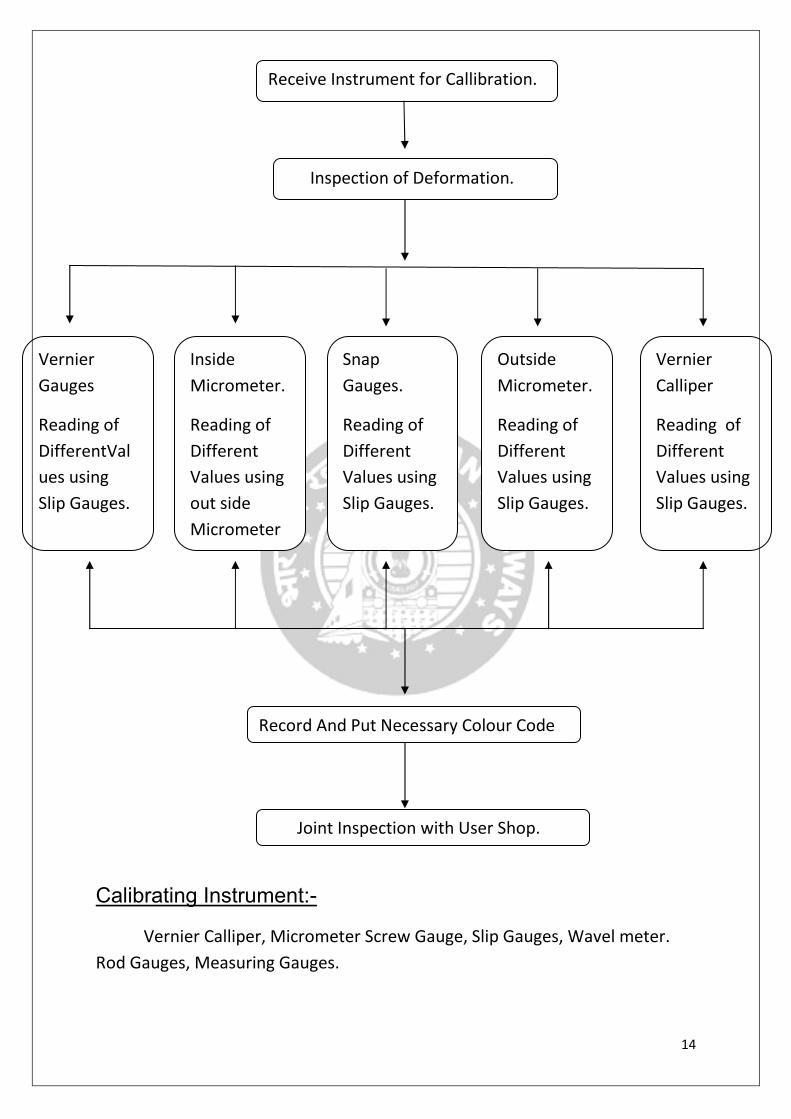
14
Calibrating Instrument:-
Vernier Calliper, Micrometer Screw Gauge, Slip Gauges, Wavel meter.
Rod Gauges, Measuring Gauges.
Receive Instrument for Callibration.
Inspection of Deformation.
Vernier
Gauges
Reading of
DifferentVal
ues using
Slip Gauges.
Inside
Micrometer.
Reading of
Different
Values using
out side
Micrometer
Snap
Gauges.
Reading of
Different
Values using
Slip Gauges.
Outside
Micrometer.
Reading of
Different
Values using
Slip Gauges.
Vernier
Calliper
Reading of
Different
Values using
Slip Gauges.
Record And Put Necessary Colour Code
Joint Inspection with User Shop.

15
Vernier Calliper
Machining Process:-
1-Milling.
2-Turning.
3-Drilling.
4-Grinding.
5-Facing.
6-Tapering.
OTHER ACTIVITIES:
1. Wheel Profile Making
2. Preparation of jigs, dies and Fixtures
16
SHOCK ABSORBER SECTION
INTRODUCTION-
� A shock absorber is a mechanical device designed to smooth out or damp
shock impulse, and dissipate kinetic energy.
� The shock absorber section of the carriage workshop carries out POH of
secondary suspension shock absorbers (hydraulic) of main line and emu
coaches.
� While shock absorbers serve the purpose of limiting excessive suspension
movement, their intended sole purpose is to dampen spring oscillations.
� Shock absorber section comprise of repairing and maintenance of Sec
suspension. Shock Absorber absorbs the additional reverse vibration and
surge produce by secondary Bolster spring.
� In railway, shock absorbers reduce the effect of travelling over uneven
tracks (at joints and while changing the tracks), leading to improved ride
quality and increase in comfort.
TYPES OF SHOCK ABSORBERS USED IN MATUNGA
WORKSHOP:-
They are classified as follows
1.According to load bearing capacity
a- 100 to 200 kg
b- 600 kg (Trailer Coach )
c-900 kg (Motor Coach)
2.According to Manufacturing Companies
a. Gabriel
b.Escort
c.Knorr
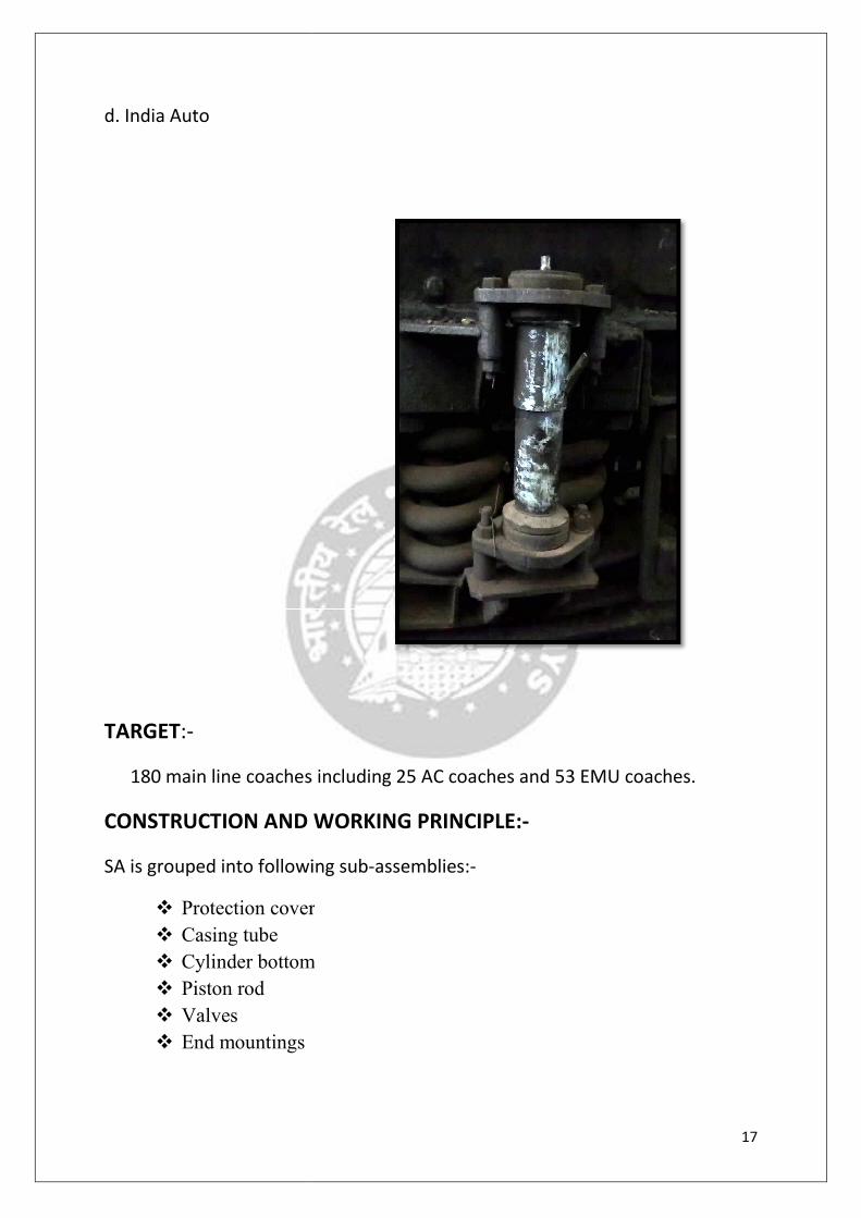
d. India Auto
TARGET:-
180 main line coaches including 25 AC coaches and 53 EMU coaches.
CONSTRUCTION AND WORKING PRINCIPLE
SA is grouped into following sub
� Protection cover
� Casing tube
� Cylinder bottom
� Piston rod
� Valves
� End mountings
180 main line coaches including 25 AC coaches and 53 EMU coaches.
CONSTRUCTION AND WORKING PRINCIPLE:-
SA is grouped into following sub-assemblies:-
Protection cover
Cylinder bottom
17
180 main line coaches including 25 AC coaches and 53 EMU coaches.
18
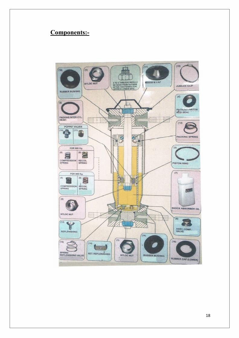
Components:-

19
Procedure Adopted For the POH of Shock:-
Arrival of Shock Absorber
Removal of Flanges
Load Testing and Visual Checking of
Dispatch
Removal of Dowel Pin and Protection tube
Assembly, Colouring
Replacement of Worn out Components.
Cleaning of Components with the use of

20
TESTING OF SA
� SA are tested with the help of dynamic test machine
� The machine draws a graph of compression and tension of SA
� A test load of +/- 20% the specified value states that the SA is proper
COMPONENTS OF POH OF SA
� Test load is within +/- 20 % the specified value
� SA is not damaged externally
� No oil leakage observed
� SA is not due for overhauling(within specified periodicity or less than 4
lakh km)
IMPROVEMENTS DONE IN SA TIL DATE:-
� Stud was provided with flat on one side and a chamfer of 2 * 45degree (to
fit directly on the bench)
� Rubber cap (lower) was replaced (water accumulation problem
eliminated)
� Sleeve was provided with chamfer of 6*45 degree(allows flow of
chemicals during cleaning)
� Piston rod flat length was extended(ensures proper tightening of nuts)
� Springs were guided by clips
ULTRASONIC CLEANING MACHINE:-
The MTN workshop employs a ultrasonic machine for cleaning components of
SA, with a capacity of 243L.
� Model no. :- D-4000H
� Cost: 470931 INR
� Power requirement: 400W
� Tank dimensions: 900*600*450 mm

21
AIR SPRING SUSPENSION
Almost all railway vehicles use bogies to carry and guide the body along the
track. They first appeared in the 1960s and were considered somewhat of a
novelty at the time but, nowadays, air suspension is a standard fitting for
passenger vehicles.
Generally, the entire load of the vehicle is shared by the various springs
Present in the bogie. These springs provide the required cushioning for the
Vehicle. When loading on the vehicle varies which invariably happens, the
“Ride Height” of that vehicle varies accordingly. It manifests in the form of
Variation in “Coupling Height” of a train formation.The “Ride Height” of the
Vehicle is important to maintain parity with the way-side “platform” level
and Vehicle floor level.
To maintain “Passenger Comfort” in rolling and pitching, the ride height of
the Vehicle and the coupling height between vehicles in a formation, an
extra Cushioning is provided in form of air suspension. The air suspension
Comprises mainly of two parts.
1. Air Spring Assembly
2. Pneumatic Control System to maintain constant height independent
of load.

22
WORKING PRINCIPLE:-
� It is used in bogie as a secondary suspension
� The air suspension in modern chassis is a combination of finely tuned
assemblies:-
� The air spring bellows and the rubber-metal bearer spring, which supports
the system especially when there is torsional strain and large horizontal
excursions
� It also absorbs a portion of the vertical deflection and reacts as an
emergency springs
� Conitech and Pheonix air spring systems play a key role in the secondary
suspension
� It’s all a matter of the air: air springs have a low natural frequency,
which minimizes the transmission of vibrations
� Another advantage is the constant leveling function which maintains the
vehicle body at a constant leveling function which maintains the vehicle
body at a constant height- regardless whether it is full of passengers or
empty
� And with the pneumatic height control, the train car exits can be adapted
precisely to the height of the station platform
23
TESTING OF AIR SPRING SUSPENSION:-
1. Place the spring assembly in test rig
2. Connect air supply to air spring and raise the air pressure to 7.3 kgs/cm2
3. Close the air supply source
4. Hold on test for 60 min
5. Take pressure reading(kg/cm2) after 60 min
6. Pressure loss of 0.3 kg/cm2 will constitute a satisfactory test
7. This completes the test.

24
TROLLEY REPAIR SHOP (EMU/MAINLINE)
INTRODUCTION-
This shop deals with the trolley repair of main line and EMU coaches. Once the
coach is lifted the trolley is send to this shop. In this shop the wheel set is
dismantled and sent to wheel shop.
This Section is divided into two subdivisions
1.Main line trolley repair section.
2.EMU trolley repair section
Types of trolleys:
1. In EMU trolley repair section.
� Motor coach trolley.
� Trailer coach trolley
2. In main line trolley repair section.
� 13 Ton trolley � 16 Ton trolley
Motor coach trolleys are used on motor coaches and having relatively high
load carrying capacity where as trailer coach trolleys are having relatively low
load carrying capacities. 13 ton bosies are used on ordinary coaches such as
Non-AC coaches, general coaches where as 16 ton bogies are used on AC
coaches, VHP coaches, coaches of Shatabdi Express. 16 ton bogies are heavy in
construction.
Difference between 13 ton and 16 ton bogies: -
1. The construction of bogie frame is box type; in case of 16 ton bogies
where as construction of bogies is I section in case of 13 ton bogies.
2. The thickness of frame of 16 ton bogie is 16 mm; whereas the thickness
of frame of 13 ton bogies is 12 mm.

25
3. The difference between 16 ton bogie & 13 is longitudinal distance
between the centers of two opposite hanger pins.
4. The center distance in 16 ton bogies is generally 1500 mm and the center
distance in 13 ton bogie is generally 1400 mm.
5. The bolster of 16 ton bogie is large and heavy than that in 13 ton bogies.
6. 16 T is generally used in AC coaches, whereas 13T in NON AC coaches.
While assembling the Bogie different clearances are taken into
account:-
• Body bolster to bogie clearance
• Bogie bolsters clearance
• Axle spring height
• Bolster spring height
• Crown clearance
• Buffer height
Sequence of operation:-
• De wheeling/ lifting of bogies
• Stripping of brake gear components
• Bogie clearing and dipping in bosch tank
• Stripping of suspension item
• Bogie trammeling, inspection, dashpot assembly
• De bushing
• Mounting of brake gear components
• Stripping as assembly of bolster
• Bogies painting, loose components painted at stages Re wheeling/
levering of bogies

26
FLOW CHART OF TROLLEY SHOP:-
Receipt Of trolley From Lifting
Machine
Unloading Break System
Removal of Electrical Components
Unloading Wheels & Axel
Unloading Suspension
Dash Dot Cleaning & Assembly
Bolster Plate And Coil Spring
Dissemble
LUF Shop
Wheel Shop
Insp. Of Bolster
Plate And Upper
Frame Spring
Test
Repair Of Bolster Plate & trolley Upper
Frame
Assembly Of Trolley
Dispatch To Lifting Shop
Electrical
Shop

27
Bogie:-
Bogie is most important part as it takes the whole weight of a coach along
with the passengers and drives them to the destinations.
Main parts of the Bogie are:-
1. Bogie frame 7. Air braking system
2.Bolster 8. Silent block
a. Upper bolster plank 9. Side bearers
b.Lower bolster plank
3. Hanger 10. Brake Shoe
11. Bolster Guide
4. Primary suspension
5. secondary suspension 12.Bearing block
6. Wheels

28
� Bogie Frame
Can be steel plate or cast steel. In this case, it is a modern design of welded
steel box format where the structure is formed into hollow sections of the
required shape.
� Bogie Transom
Transverse structural member of bogie frame (usually two off) which also
supports the car body guidance parts and the traction motors.
� Brake cylinder
An air brake cylinder is provided for each wheel. A cylinder can operate tread
or disc brakes. Some designs incorporate parking brake as well.
Some bogies have two brake cylinders per wheel for heavy duty braking
requirements. Each wheel is provided with a brake disc on each side and a
brake pad actuated by the brake cylinder.
A pair of pads is hung from the bogie frame and activated by link attached to
the piston in the brake cylinder. When air is admitted into the brake cylinder,
the internal piston moves these links and causes the brake pads to press
against the discs.
A brake hanger support bracket carries the brake hangers, from which the pads
are hung.
� Primary Suspension Coil
A steel coil spring, two of which are fitted to each axle box in this design. They
carry the weight of the bogie frame and anything attached to it.
� Hanger
Hanger holds the Bolster assembly with the frame of the trolley. It is the most
important link for the load transmission.
� BOLSTER:
Carries the secondary suspension
� Gear box
This contains the pinion and gear wheel which connects the drive from the
armature to the axle.

29
� Lifting Lug:
Allows the bogie to be lifted by a crane without the need to tie chains or ropes
around the frame
� Secondary Suspension
Rubber air suspension bags are provided as the secondary suspension system
for most modern trains. The air is supplied from the train’s compressed air
system.
� Shock Absorber
To reduce the effect of vibration occurring as a result of the wheel / rail
interface.
� Axle box Cover
Simple protection for the return current brush, if fitted, and the axle bearing
lubrication.
� Dash Pot
It is used as a primary suspension and it also helps in turning of the bogie.
� Anchor Link
It is used to connect BOLSTER with the BOGIE FRAME. It is connected
diagonally.
SMITHY SHOP:-
This shop does all the repair and inspection of the parts
disassembled in the trolley shop. The various machines in the smithy shop are:
SMTHY SHOP
Eye Rolling Machine 1
Hydraulic Buckling press 1
Hydraulic De Buckling press 1

30
Drop Stamp Hammer 5
Pneumatic Hammer 8
Shearing Machine 2
Shearing/Nibbling Machine 1
Spring Testing Machine 1
TESTING OF COILED SPRINGS:-
� Place the coiled spring on the SPRING TESTING MACHINE. Note the
initial size of the spring.
� Apply a specific weight and note the size of the spring in compressed
condition. The difference in the readings makes it possible to classify
springs by virtue of load they can bear.
� The color codes in decreasing order of load bearing capacity are yellow, blue and green.
31
WHEEL SHOP
INTRODUCTION:-
Wheel shop is one of the most important shops in the workshop as it deals
with the repair work of wheel, the main part of the train. After receiving the
wheel set from the trolley repair shop, depending upon the amount of
damage, the wheel undergoes normal repair or heavy repair.
Wheel shop is sub-divided into:
� Wheel repair Shop
� Wheel inspection Shop
� Wheel assembly
� Roller bearing
TYPES OF WHEELS:
� Tyre with Skeleton
� Solid wheel
AXLE TYPES:
• 13T- Dia 145 mm for sleeper coach
• 16T- Dia 152 mm for AC coach
• 130 mm Dia for main line coach
• 140 m Dia for Motor coach and HCC coaches.

Main Activities Carried out in Wheel shop:
� Normal repair
� Re- Discing of wheel
� Re-Axeling of wheel
� Re-Gearing of Wheel
Components of wheel Set:
A wheel set is a assembly mainly of two components.
• Wheel discs (soli
• An axel to hold these wheel discs in position
The activities involved
a. Pre-inspection of incoming Wheel
Main Activities Carried out in Wheel shop:-
wheel
Axeling of wheel
Gearing of Wheel
Components of wheel Set:
A wheel set is a assembly mainly of two components.
Wheel discs (solid) on both sides of the axle
An axel to hold these wheel discs in position
The activities involved in Normal Repair Wheels are as follows:
inspection of incoming Wheel
32
in Normal Repair Wheels are as follows:-

33
b. Drop axle boxes and clean and inspect them in electric oven
c. Carry out Ultra sonis test on axle
d. Dismount Bearings and test them
e. Clean Roller bearings and clean them
f. Pack fresh grease and mount all the components properly.
Different Defects Which Occurs in Wheel:-
� Thermal cracks
� Chatter
� Shattered Rim
� Plate cracks
� Spread Rim
� Loose Assembly
INSPECTION OF WHEELS:
� VISUAL INSPEC TON: • This is the first step in the inspection of wheels and may be
always done with the unaided eye or by using hand lens.
• Although a seemingly elementary procedure, it should be
carried out carefully and systematically on every wheel.
• The length, Diameter, Profile is checked here.
� SOUND TEST: • After undergoing visual inspection the wheel has to undergo
sound test.
• In this test when a hammer is struck sharply on the region free
from internal flaws it emits the clear ringing note whereas a region
with large internal flaws a flat unusual note.
• This test gives valuable information to the skilled operator about
the amount of crack that has occurred on the Wheel.
34
� ULTRASONIC TEST:-
• After Going through sound test the wheel has to undergo an
ultrasonic test for the detection of internal or invisible cracks.
• It is one of the non destructive testing. It relies upon transmission
and reflection of ultrasonic beams or waves of frequency between
25 KHz and 100 KHz.
• The Ultrasonic Waves are usually produced by the Piezoelectric
effect within the crystal probe which is placed on the surface of the
specimen.
• Discontinuities below the surface cause reflection of the ultrasonic
waves which appear as peaks upon cathode ray oscilloscope
receiver.
• The size of peek seen on the receiving tube is some indication of the
size of defect.
• The crystal probe thus becomes the receiver as well as the
transmitter.
• Ultrasonic techniques are useful for detecting cracks, voids and
defects below the surface as well as near the surface.
� The Dimensions of Wheel Sheets are:
1. 169mm to 175mm for Trailor.
2. 169mm to 180mm for ICF
3. 190mm to 195mm for Motor Coach.
� The Dimensions of Shoulder are:
1. 145mm for Trailor Coach
2. 160mm for Motor Coach.
� The Dimensions of Journal are
1. 130.04mm for Trailor Coach.
2. 140.04mm for Motor Coach.
� The length of the Axle are. 1. 2316 for ICF Trailor 2. 2286 for ICF Mail
3. 2362 for Motor Coach.
35
If the dimensions of any component are below these permissible then
the components are condemned.
� Difference between two wheels of one trolley= 5 mm.
� Difference between two dia of wheels of two trolley =13mm.
The main Machines used here are:-
WHEEL LATHE:
• Wheel lathe is one of the important machines in the wheel shop.
The basic operation performed on this machine is turning
operation. The wheel is turned to the required diameter.
• It is huge in construction. Wheel lathe is placed on a huge
platform. It consists of two headstocks. Both the centers are live
centers. It has two tool posts. Tool post can move on the guide
ways provided. The chucks used are four jaw universal types.
JOURNAL GRINDING MACHINE:
• The basic operation performed on this machine is grinding of
jounal. Both the abrading wheel as well as the journal rotates.
• In addition to basic operation the machine can also perform
turning the facing operations. The tool material used for this is
‘Cemented Carbide’.
AXLE TURNING LATHE:
• The CNC used over here is basically a turning lathe. It is
used for turning axle from a raw material.’Fanuc
Controller’ is employed in this machine. Controller
receives the signal (electrical) from tape reader and causes
the machine to respond.
• A program containing blocks of number and alphabets is
fed to controller. The controller receives the electrical
signal and causes the machine to respond. It is
accompanied by a hoist for handling the axle on and off
the machine.

36
AXLE JOURNAL TURNING & BURNISHING (AJTB):
• Axle journal turning can also be performed on this
machine. Turning does not release the desired surface
finish; hence burnishing a finishing process is employed
after turning the axle.
• Burnishing is the process in which a roller is pressed
against the axle because of this pressure the finishing of
the axle is done. There is hardly any material removed.
This process not only finishes the axle but also hardens it.
A crane also accompanies this machine.

37
ROLLER BEARING
Purpose-
The major purpose of bearing is to reduce the friction and to promote smooth
rotational motion to the trolley and bogie, so that the rotary motion is
restricted only to axel, where as the bearing box remains stationary.
Types:-
1. Spherical type Roller Bearing 2. Cylindrical type Roller Bearing 3. Taper type Roller Bearing
Parts of Roller Bearing:-
1. Outer Race 2. Inner Race
3. Roller 4. Cage 5. Spacer Ring
38
Inspection of bearing:-
1. Noise 2. Seals 3. Temperature
4. Lubrication
Bearing clearing plant:
This plant is used for clearing the used bearings. It consists of:
• Pre wash Chamber 2050 ltr
• Washing Chamber 2050 ltr 2 to 4 % chemical
• Rinse Chamber 1120 ltr 2 to 4 % chemical
• Dip Chamber 416 ltr 32 % chemical
� The bearing first undergoes Pre-washing where it is cleaned with the hot water. The temperature of the water is about 156 F. After passing through
this chamber, the bearing passes through chambers which contain higher
proportion of chemical (Genolite).
The cycle of clearing requires 3 minutes.
Bearing mounting:-
� There is not any kind of press fit between the bearing and the journal and hence the question of using a press ends over there.
� Being a heat sunk fit; the bearing is heated by means of an induction
heater where the bearing is heated up to 120℃. Automatic timer is
around 3 minutes per bearing.
Bearing dismounting:-
� As there is a heat sunk fit between the journal and the bearing, it cannot be removed in any ordinary method. Bearing is removed by using a
hydraulically operated device. The principle of the device is that the oil
under pressure
� (about 500 kg/cm2)
� Enters between the journal and the shaft and forces out the bearing and hence removal of bearing becomes relatively easier.
CAUSES OF BEARING FAILURE:- TYPES OF DEFECTS
• Increased load (due to impact) 1. Outer and inner race
cracked
39
• Increased velocity 2. Roller flaked.
• Improper lubrication 3. Roller pitted.
• Misalignment 4. Roller cracked.
• Exposure to dirt 5. Depressed cage
Types of spherical roller bearings:-
Sr. no TYPE RADIAL CLEARANCE NO. OF
ROLLERS
1 SKF 0.105-0.296 mm 30
2 FAG/ NORMA 0.080-0.185 mm 28
3 NEI/ NBC 0.080-0.190 mm 28
The running capacity of bearing is 2.00.000.
Checking After every 18 months.
Out Turn 60 to 70 bearings.
Cost: About 10,000 Rs.
ZYGLO TEST:-
a) Dip the bearing in Fluorescent Penitrant Dilephor.
b) Remove it, spray dilephor powder on it.
c) Check the bearing in ultra violet lamp for the smallest crack in it.

40
LUF (LIFTING UNDER FRAME) LUF (LIFTING UNDER FRAME) LUF (LIFTING UNDER FRAME) LUF (LIFTING UNDER FRAME) SHOPSHOPSHOPSHOP & AIR BRAKE
INTRODUCTION:-
� The coaches who are entitled for periodical overhauling(P.O.H) are made
to halt at Dadar yard from where 7 to 8 coaches are taken to Matunga
workshop daily.Once the coach enters the workshop it is brought to the
lifting and under frame section where entire coach is lifted with the help
of 2 cranes having the capacity of 25 tones each.Once the coach is lifted
the trolley is sent to the trolley repair shop.An inspection team is
appointed to inspect the amount of corrosion occurred on the entire coach
and then if any corrosion repair work is required then it is sent to the
heavy corrosion repair shop.
� L.U.F. is subdivided into four Sub-divisions:
1. Air brake equipment section
2. DV repair section
3. Brake cylinder section
4. Air brake and piping
DISSEMBLY OF PARTS:-
Usually coach is connected with trol
1] Center pivot & Side bearers 2] Brake cylinder pipe
Hence for removal of trolley from the coach, the cotter pin of center pivot is
removed and branch pipes of brake cylinder are disconnected
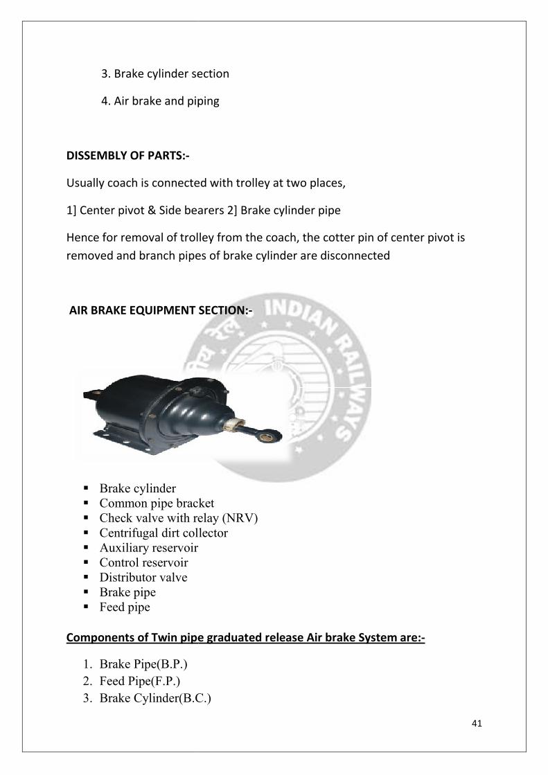
AIR BRAKE EQUIPMENT SECTION:
� Brake cylinder
� Common pipe bracket
� Check valve with relay (
� Centrifugal dirt collector
� Auxiliary reservoir
� Control reservoir
� Distributor valve
� Brake pipe
� Feed pipe
Components of Twin pipe graduated release Air brake System are:
1. Brake Pipe(B.P.)
2. Feed Pipe(F.P.)
3. Brake Cylinder(B.C.)
3. Brake cylinder section
4. Air brake and piping
Usually coach is connected with trolley at two places,
1] Center pivot & Side bearers 2] Brake cylinder pipe
Hence for removal of trolley from the coach, the cotter pin of center pivot is
removed and branch pipes of brake cylinder are disconnected
AIR BRAKE EQUIPMENT SECTION:-
Common pipe bracket
Check valve with relay (NRV)
Centrifugal dirt collector
pipe graduated release Air brake System are:
Brake Cylinder(B.C.)
41
Hence for removal of trolley from the coach, the cotter pin of center pivot is
pipe graduated release Air brake System are:-

42
4. Auxiliary Reservoir(A.R.)
5. Isolating Cock with filter(I.C.)
6. Distributor Valve(D.V.)
7. Controlled Reservoir(C.R.)
8. Isolating Cock
9. Non return valve with choke
10. Cut off angle cock 11. Air hose coupling(B.P.) 12. Air hose coupling(F.P.) 13. Palm end
14. Guard Emergency Valve(G.E.V.)
15. Pressure Gauge(B.P.) 16. Pressure Gauge(F.P.) 17. Branch Pipe 18. Chain 19. .Passenger Emergency Alarm Signal Device(PEASD)
20. Alarm Signal Light
21. Alarm Signal Disc
22. Passenger Emergency Valve(PEV)
23. Micro switch
24. Slack Adjustor 25. Isolating Cock
26 .Release Valve.
� DISTRIBUTOR VALVE(D.V.) SECTION:-
Almost all components of air brake system D.V.is the most important
element of the air brake system.
� Heart of the Air Brake System
� D.V. senses pressure drop in the brake system
Functions of D.V. are:-
1. It charges the air brake system
2. It helps in graduated brake application
3. It helps in graduated brake release
4. It limits maximum brake cylinder pressure for full service
application/emergency application
5. It controls the time for brake application and brake release
depending on service condition

43
6. It facilitates complete discharge of air from air brake system
7. It protects overcharging of control reservoir
8. It propagates reduction of pressure in brake pipe quickly
Stages for Distributor Valve(D.V.):-
Charging Condition:-
Brake Application
44
Following are the two designs of D.V.:
� C3W type D.V.{Knoor and Escort}
� K.E. type D.V.{Greysham,Stone India Ltd.,Sab WAb Co.}
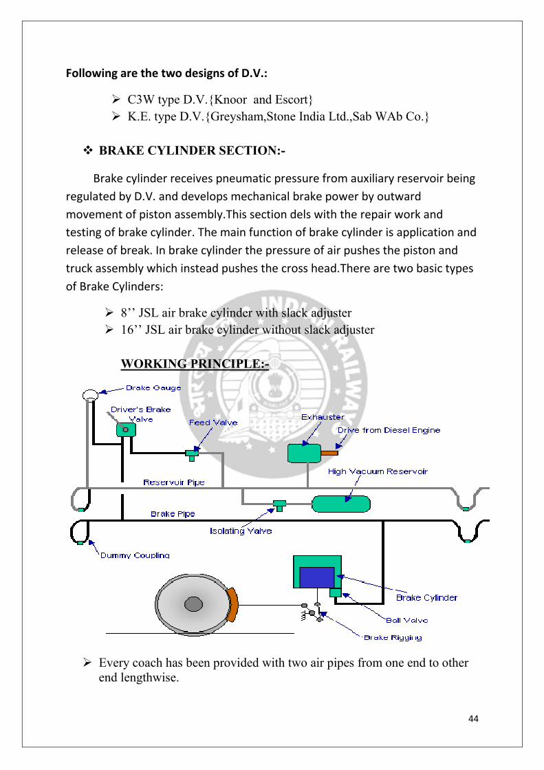
� BRAKE CYLINDER SECTION:-
Brake cylinder receives pneumatic pressure from auxiliary reservoir being
regulated by D.V. and develops mechanical brake power by outward
movement of piston assembly.This section dels with the repair work and
testing of brake cylinder. The main function of brake cylinder is application and
release of break. In brake cylinder the pressure of air pushes the piston and
truck assembly which instead pushes the cross head.There are two basic types
of Brake Cylinders:
� 8’’ JSL air brake cylinder with slack adjuster
� 16’’ JSL air brake cylinder without slack adjuster
WORKING PRINCIPLE:-
� Every coach has been provided with two air pipes from one end to other
end lengthwise.

45
� One pipe is used to continuously charge the compressed air to auxiliary
reservoir and is called as feed pipe.
� The second pipe is used for the application and releasing of breaks and is termed as brake pipe. As such this system is called as twin pipe system.
This system has following merits.
� Working principle:
1. Feed pipe charges the auxiliary reservoir continuously and maintains
the predetermined air pressure in auxiliary reservoirs.
2. On application of brakes the auxiliary reservoir, the application
compressed air is fade to the brake cylinder and there is certain fall in
air pressure in auxiliary reservoir due to same. But the feed pipe
immediately charges auxiliary reservoir and maintains desired air
pressure.
Any no. of brake application and releasing may be done by the driver in
quick succession; the air pressure in auxiliary reservoir will remain the
same that is there will be no decrease in air pressure in it. This feature is
not possible in case of feed pipe is removed from air brake system,
because the brake pipe will have to shoulder the burden of feed pipe in
addition to its own job.
3. In case due to any reason one pipe of a coach or a wagon gets damaged
or goes defective, it can be bypassed in twin pipe system and the
detachment of coach or a wagon would not be essential as in the case
the train will be worked as a single pipe system.
� CHARGING
• When the passenger pulls the alarm chain PEASD(passenger emergency
alarm signal device) is operated, which in turn operates PEAV(passenger
emergency alarm valve) to connect brake pipe to atmospheric pressure
through a choke.
• This action reduces brake pipe pressure which leads to partial application
of brakes on the coach, simultaneously micro switch installed in the
PEAV is energized which gies an audio/visual to the driver or guard of
the train. Also an indication reaches in the form of drop in pressure of BP
and is observed in the flow meter of the locomotive. This drop in pressure
is just sufficient to apply partial brakes and provide an indication to driver
to stop the train.

46
INSPECTION DEPARTMENTINSPECTION DEPARTMENTINSPECTION DEPARTMENTINSPECTION DEPARTMENT
INTRODUCTION:-
• The term “Inspection” refers to checking of any things for its correctness.
• In Railway Workshop every part of the Bogie & the Coach is inspected
for its correctness by Inspection Department.
• There are various Inspection Departments:-
1. EMU Inspection:-
• In this department under frame visual inspection of EMU trains are
carried out for its corrosion or cracks at welding joints of parts like
centre pivot, side bearers, head stock, body side panel, body side
pillars, trough floor, sole bars.
• Camber measurement of sole bar is also carried out in this department
& report send to EMU rehab.
• Buffer Inspection is made to check the height between buffer centre &
track.
2. Main Line Inspection:-
• In the department under frame visual inspection of main line coaches
are carried out for its corrosion or cracks at welding joints of parts like
centre pivot, side bearers, headstock, body panel, body side pillars,
trough floor, sole bars.
• Camber measurement of sole bar is also carried out in this department
& report send to EMU rehab.
• Buffer Inspection is made to check the height between buffer center &
track.
3. Water tank:-
• Water tanks are checked for its leakage by filling water inside the
tanks.
4. Pit Line Inspection:-
In this department various elements are inspected

47
• Spring heights
• Bolster to Bogie clearance
• Bogie to Coach clearance
• Wheel size marked on Wheels.
5. Carpentry Inspection:-
Here in this department interiors of coaches are checked.
6. Wheel Inspection:-
a. Checking of profile, diameter and length.
b. Ultrasonic test
c. Hammer test

48
CONCLUSIONCONCLUSIONCONCLUSIONCONCLUSION
• It had been an outright pleasure for us to get a chance to work in Carriage
Workshop, Central Railway, Matunga.
• At the end of our training term, which is the most exciting, enriching and
challenging experience in our engineering curriculum. We wish to
summarize the benefits acquired over the period. This training has
certainly helped us in bridging the gap between the theory and practical.
It enables us to see how the knowledge gained through textbooks is
finally implemented in practice. It provided us an opportunity to learn
under a different environment. We gained a lot of things from this
training and they are mentioned below.
• This training has offered us an exposure to industry, which cannot be
simulated in an engineering college.
• We understood the scope and the responsibility as well as managerial
skills at the various product units of the company.
• It enabled us to get familiarize with Railway Organization where in we
learned Air Brake system. Apart from all the main cause for low
efficiency of the plant is Corrosion. Thus Railway has to take
precautionary measures to reduce corrosion.
• Thus, we confidently conclude that this training was most beneficial and
an informative experience, which is bound to help us in the future.

49
BIBLIOGRAPHY
Websites:-
� www.howstuffworks.com
� www.mytrainsonline.com
� www.shockabsorber.co.uk
� www.railway-technical.com