Embed Size (px)
Citation preview

Massive MIMO testbed: Validation STEFFEN MALKOWSKY, LUND UNIVERSITY, SWEDEN
Why do we need a testbed?
2
Ø Theoretical results show that massive MIMO has very promising features for future wireless generation, however they cannot answer all questions:
1) How does it perform under real-life conditions? 2) How can we model massive MIMO channels?
3) Implementation challenges/issues? 4) Required reciprocity calibration accuracy?
5) Is pilot contamination a problem?

3
LUMAMI TESTBED

LuMaMi Testbed: Parameters
4
Ø 100 BS antennas Ø Serving up to 12 UEs Ø 50 SDRs + 6 SDRs as UEs
Ø 4 Central Processing units performing MIMO processing
Ø 3.7 GHz carrier frequency
Ø LTE-like parameters Ø Uncoded transmission

LuMaMi Testbed: Processing
5
O FDM TX/RXAntenna Com bi ner/
BW splitter
O FDM TX/RX
O FDM TX/RX
O FDM TX/RX
O FDM TX/RX
O FDM TX/RX
O FDM TX/RX
O FDM TX/RX
BW Combiner/Antenna Splitter
SubbandChannelEstimate
Subband MIMOPrecoder
WMM SE
QAM Demapping
QAM Mapping
SubbandGenerate
MMSE Matrix
SubbandMIMO
Detector
8x
….
SubbandChannelEstimate
Subband MIMOPrecoder
WMM SE
QAM Demapping
QAM Mapping
SubbandGenerate
MMSE Matrix
SubbandMIMO
Detector
8x
….
SubbandChannelEstimate
Subband MIMOPrecoder
WMM SE
QAM Demapping
QAM Mapping
SubbandGenerate
MMSE Matrix
SubbandMIMO
DetectorNI USRP-2943R SDR
PXIe-8135 Controller
PXIe-7976R FlexRIO
SubbandChannelEstimate
Subband MIMO
Precoder
WMMSE
OFDM TX/RXAntenna Combiner/
BW splitter
OFDM TX/RX
OFDM TX/RX
OFDM TX/RX
OFDM TX/RX
OFDM TX/RX
OFDM TX/RX
OFDM TX/RX
BW Combiner/Antenna Splitter
Group of 8 USRP RIOs
8x
….
8x
….
BW Combining
(bytes)
Video Display
QAM Demapping
QAM Mapping
BW Splitting (bytes)
Video Streaming
System Configuration
Channel Visualization
SubbandGenerate
MMSE Matrix
SubbandMIMO
Detector
8x
….
8x
….
Up to (4) MIMO Processor FPGAs
Up to (8) Groups of 8 USRP RIOs (16 antennas per group)
8x
….
8x
….
8x
….
8x
….
8x
….
Ø Per-antenna (OFDM) processing performed on USRP SDR Ø Data of up to 8 USRPs combined and send to centralized
processing

LuMaMi Testbed: Processing
6
O FDM TX/RXAntenna Com bi ner/
BW splitter
O FDM TX/RX
O FDM TX/RX
O FDM TX/RX
O FDM TX/RX
O FDM TX/RX
O FDM TX/RX
O FDM TX/RX
BW Combiner/Antenna Splitter
SubbandChannelEstimate
Subband MIMOPrecoder
WMM SE
QAM Demapping
QAM Mapping
SubbandGenerate
MMSE Matrix
SubbandMIMO
Detector
8x
….
SubbandChannelEstimate
Subband MIMOPrecoder
WMM SE
QAM Demapping
QAM Mapping
SubbandGenerate
MMSE Matrix
SubbandMIMO
Detector
8x
….
SubbandChannelEstimate
Subband MIMOPrecoder
WMM SE
QAM Demapping
QAM Mapping
SubbandGenerate
MMSE Matrix
SubbandMIMO
DetectorNI USRP-2943R SDR
PXIe-8135 Controller
PXIe-7976R FlexRIO
SubbandChannelEstimate
Subband MIMO
Precoder
WMMSE
OFDM TX/RXAntenna Combiner/
BW splitter
OFDM TX/RX
OFDM TX/RX
OFDM TX/RX
OFDM TX/RX
OFDM TX/RX
OFDM TX/RX
OFDM TX/RX
BW Combiner/Antenna Splitter
Group of 8 USRP RIOs
8x
….
8x
….
BW Combining
(bytes)
Video Display
QAM Demapping
QAM Mapping
BW Splitting (bytes)
Video Streaming
System Configuration
Channel Visualization
SubbandGenerate
MMSE Matrix
SubbandMIMO
Detector
8x
….
8x
….
Up to (4) MIMO Processor FPGAs
Up to (8) Groups of 8 USRP RIOs (16 antennas per group)
8x
….
8x
….
8x
….
8x
….
8x
….
Ø Centralized processing distributed over 4 units, each working on ¼ bandwidth
Ø 3 detector types implemented: MRC/MRT, ZF and regularized ZF

LuMaMi Testbed: Processing
7
O FDM TX/RXAntenna Com bi ner/
BW splitter
O FDM TX/RX
O FDM TX/RX
O FDM TX/RX
O FDM TX/RX
O FDM TX/RX
O FDM TX/RX
O FDM TX/RX
BW Combiner/Antenna Splitter
SubbandChannelEstimate
Subband MIMOPrecoder
WMM SE
QAM Demapping
QAM Mapping
SubbandGenerate
MMSE Matrix
SubbandMIMO
Detector
8x
….
SubbandChannelEstimate
Subband MIMOPrecoder
WMM SE
QAM Demapping
QAM Mapping
SubbandGenerate
MMSE Matrix
SubbandMIMO
Detector
8x
….
SubbandChannelEstimate
Subband MIMOPrecoder
WMM SE
QAM Demapping
QAM Mapping
SubbandGenerate
MMSE Matrix
SubbandMIMO
DetectorNI USRP-2943R SDR
PXIe-8135 Controller
PXIe-7976R FlexRIO
SubbandChannelEstimate
Subband MIMO
Precoder
WMMSE
OFDM TX/RXAntenna Combiner/
BW splitter
OFDM TX/RX
OFDM TX/RX
OFDM TX/RX
OFDM TX/RX
OFDM TX/RX
OFDM TX/RX
OFDM TX/RX
BW Combiner/Antenna Splitter
Group of 8 USRP RIOs
8x
….
8x
….
BW Combining
(bytes)
Video Display
QAM Demapping
QAM Mapping
BW Splitting (bytes)
Video Streaming
System Configuration
Channel Visualization
SubbandGenerate
MMSE Matrix
SubbandMIMO
Detector
8x
….
8x
….
Up to (4) MIMO Processor FPGAs
Up to (8) Groups of 8 USRP RIOs (16 antennas per group)
8x
….
8x
….
8x
….
8x
….
8x
….
Ø A standard windows computer hosts the complete system Ø Configures system Ø Visualizes parameters, e.g. channel impulse response and
acts as source and sink for video streams

8
FOUR TESTS
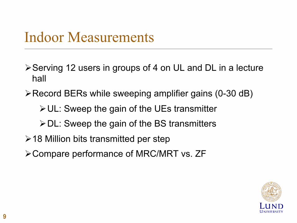
Indoor Measurements
Ø Serving 12 users in groups of 4 on UL and DL in a lecture hall
Ø Record BERs while sweeping amplifier gains (0-30 dB)
Ø UL: Sweep the gain of the UEs transmitter Ø DL: Sweep the gain of the BS transmitters
Ø 18 Million bits transmitted per step Ø Compare performance of MRC/MRT vs. ZF
9

Setup
10
Closely spaced UEs
BS Base station placed at the front of the lecture hall
Users are distributed in groups of 4 with close spacing inside each group

Amplifier Gain [dB]0 10 20 30
BER
10-4
10-3
10-2
10-1
100
UE0UE1UE2UE3UE4UE5UE6UE7UE8UE9UE10UE11
T T
T
C
C
C
C
C
C
T
C
C
C
C
C
C
C
C
C
C
C
C
T
C
C
C
C
C
C
T
C
C
C
C
C
C
C
CT
C
CT
C
CT
C
C
TT
C
C
C
C
C
C
TC
C
C
C
4
5
6
7
8
9
10
11
0
1
2
3BS
Uplink BERs (QPSK)
11
TX saturates
Ø ZF detector Ø Close by users (UE8-11)
show best BERs
Ø Far users (UE0-UE3) show worst performance
Ø UE0/1 interference limited Ø Bad performance at full
power close to saturation

Gain Offset [dB]0 10 20 30
BER
10-4
10-3
10-2
10-1
100
UE0UE1UE2UE3UE4UE5UE6UE7UE8UE9UE10UE11
T T
T
C
C
C
C
C
C
T
C
C
C
C
C
C
C
C
C
C
C
C
T
C
C
C
C
C
C
T
C
C
C
C
C
C
C
CT
C
CT
C
CT
C
C
TT
C
C
C
C
C
C
TC
C
C
C
4
5
6
7
8
9
10
11
0
1
2
3BS
Uplink BERs (16-QAM)
12
TX saturates
Ø ZF detector Ø Close by users (UE8-11)
shows best BERs
Ø Far users (UE0-UE3) show worst performance
Ø UE0/1 interference limited Ø Bad performance at full
power close to saturation

Amplifier Gain [dB]0 5 10 15
BER
10-4
10-3
10-2
10-1
100
UE0UE1UE2UE3UE4UE5UE6UE7UE8UE9UE10UE11
T T
T
C
C
C
C
C
C
T
C
C
C
C
C
C
C
C
C
C
C
C
T
C
C
C
C
C
C
T
C
C
C
C
C
C
C
CT
C
CT
C
CT
C
C
TT
C
C
C
C
C
C
TC
C
C
C
4
5
6
7
8
9
10
11
0
1
2
3BS
Downlink BERs (QPSK)
13
Ø ZF precoder Ø Close by users (UE8-11)
shows best BERs
Ø Other users (UE0-7) show similar performance
Ø High performance difference between UE8-11 and the UE0-7

Gain Offset [dB]0 10 20 30
BER
10-4
10-3
10-2
10-1
100
UE0UE1UE2UE3UE4UE5UE6UE7UE8UE9UE10UE11
T T
T
C
C
C
C
C
C
T
C
C
C
C
C
C
C
C
C
C
C
C
T
C
C
C
C
C
C
T
C
C
C
C
C
C
C
CT
C
CT
C
CT
C
C
TT
C
C
C
C
C
C
TC
C
C
C
4
5
6
7
8
9
10
11
0
1
2
3BS
Downlink BERs (16-QAM)
14
BERs floor
Ø ZF detector Ø Close by users (UE8-11)
show best BERs
Ø Almost all users show a significant BER floor
Ø Performance limited by reciprocity calibration accuracy and/or interference
Drop in BER for closest users

Amplifier Gain [dB]0 10 20 30
BER
10-4
10-3
10-2
10-1
100
MRC QPSKMRC 16-QAMMRC 64-QAMZF QPSKZF 16-QAMZF 64-QAM
Amplifier Gain [dB]0 10 20 30
BER
10-4
10-3
10-2
10-1
100
MRC QPSKMRC 16-QAMMRC 64-QAMZF QPSKZF 16-QAMZF 64-QAM
ZF vs. MRC/MRT
15
Ø MRC/MRT showing significant error floors Ø Usable in practical systems?
Ø ZF far superior in real-life channels
Uplink Downlink
Floor for ZF with 64-QAM

Collaborative Measurements in Bristol
Ø First joint measurement campaign with Lund University and University of Bristol in May 2016
Ø Based on Bristol MaMi system with 128 antennas
Ø How many users can be served simultaneously? Ø What spectral efficiency can be achieved?
16

Setup
17
Base station Closely spaced users
Overall setup from base station view
Users BS
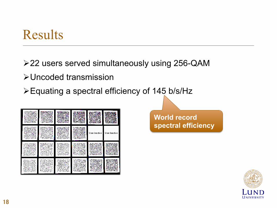
Results
Ø 22 users served simultaneously using 256-QAM Ø Uncoded transmission Ø Equating a spectral efficiency of 145 b/s/Hz
18
World record spectral efficiency

First Outdoor Trial I
19
Ø First outdoor test to see whether reciprocity calibration and over-the-air synchronization works outdoor
Ø Focus on achieving good UL and DL constellations with up to 8 users and an additional moving user
Base station with 100 antennas at the roof of the department building, with LOS to 8 UEs
UE
UE
UE BS Both out-door to out-
door and out-door to in-door transmission
UE UE
UE
UE
UE
BS
UE

First Outdoor Trial III
20
Base station with 100 antennas at the roof of the department building, with LOS to 8 UEs
UE
UE
UE BS Both out-door to out-
door and out-door to in-door transmission
UE UE
UE
UL constellations on BS ZF MRC
DL constellations with ZF
Close window half

First Outdoor Trial III
21
Base station with 100 antennas at the roof of the department building, with LOS to 8 UEs
UE
UE
UE BS Both out-door to out-
door and out-door to in-door transmission
UE UE
UE
One user in car Front Panel picture
Good looking
constellation

Joint Mobility Trials in Lund
22
Ø Together with a team from University of Bristol we performed the first mobility test using the LuMaMi testbed
Ø Goal was to analyze how well massive MIMO works in dynamic environments
Ø Tests were performed with up to 12 users, some mounted on cars (up to 40 km/h) and some mounted on cycle carts (walking speed)
Ø Uplink channel data, BERs and LabVIEW front panels were recorded

Setup / Equipment
23
Base station deployed on rooftop
Users mounted on cycle cart
Users mounted on cars

Different tested scenarios I
24
CAR
Parking lot
CAR
Cart Cart Cart Cart
Ø Gradually adding users while observing performance

Different tested scenarios II
25
CAR
Parking lot
CAR
Cart Cart Cart
Ø Scenario with 6 users as pedestrians and 4 users on cars
Ø Video including live BERs and constellations
Ø Playback recorded channel data

10 user mobility test video
26
https://www.youtube.com/watch?v=wPPMrr4rHmo
PLEASE CHECK OUT FOLLOWING LINK

Conclusions
27
Ø The LuMaMi testbed is fully functional and working for UL and DL transmission
Ø In a joint campaign Lund University and University of Bristol achieved a new world record for spectral efficiency
Ø Indoor measurements showed that even with 100 antennas at the BS, MRC/MRT show significantly worse performance than ZF
Ø Mobility measurements showed that massive MIMO works for moving users with relatively good BER performance on UL and DL (more analysis to be performed)

Frame Structure
28
ULP
ilot
ULD
ata
ULD
ata
Switc
h G
uard
DLD
ata
DLD
ata
Switc
h G
uard
Subframe#0
Subframe#1
Subframe#2
Subframe#3
Subframe#4
Subframe#9
One radio frame Tf = 10ms
One subframe Tsf = 1ms
One slot Tslot = 0.5ms