Embed Size (px)
Citation preview

Massey Ferguson 76X0/86X0/8700 Series,
AGCO DT-B Series, and Challenger MT6X5C/D/E Series - Steering Ready SmarTrax™ Installation
Manual
P/N 016-5033-005 Rev. C 12/16 E28927
Copyright 2016

While every effort has been made to ensure the accuracy of this document, Raven Industries assumes no responsibility for omissions and errors. Nor is any liability assumed for damages resulting from the use of information contained herein.
Raven Industries shall not be responsible or liable for incidental or consequential damages or a loss of anticipated benefits or profits, work stoppage or loss, or impairment of data arising out of the use, or inability to use, this system or any of its components. Raven Industries shall not be held responsible for any modifications or repairs made outside our facilities, nor damages resulting from inadequate maintenance of this system.
As with all wireless and satellite signals, several factors may affect the availability and accuracy of wireless and satellite navigation and correction services (e.g. GPS, GNSS, SBAS, etc.). Therefore, Raven Industries cannot guarantee the accuracy, integrity, continuity, or availability of these services and cannot guarantee the ability to use Raven systems, or products used as components of systems, which rely upon the reception of these signals or availability of these services. Raven Industries accepts no responsibility for the use of any of these signals or services for other than the stated purpose.
Disclaimer

Table of Contents
Chapter 1 Important Safety Information............................................................................. 1Hydraulic Safety ........................................................................................................................ 2Electrical Safety ........................................................................................................................ 2
Chapter 2 Introduction............................................................................................................. 3Preparing for Installation ........................................................................................................... 4
Recommendations ................................................................................................................................................................. 4Point of Reference ................................................................................................................................................................. 4
Updates ..................................................................................................................................... 4Kit Contents ............................................................................................................................... 5
Chapter 3 Cab Component Installation................................................................................ 9Install the SmarTrax Node ......................................................................................................... 9
Mount the SmarTrax Node - Kit 117-5033-005 ......................................................................................................... 9Mount the SmarTrax Node - Kit 117-5033-009 .......................................................................................................10Node Mounting Locations ................................................................................................................................................12
Install the Node Harness ......................................................................................................... 13Install the Foot Switch ............................................................................................................. 16Install the Power Adapter Cable .............................................................................................. 16Connect the SmarTrax System to an Existing Chassis Cable (If Applicable) .......................... 19System Diagram ...................................................................................................................... 20
Chapter 4 Startup Procedures .............................................................................................. 25
Calibrate the SmarTrax System .............................................................................................. 25Engage the Tractor’s Steering System .................................................................................... 25
P/N 016-5033-005 Rev. C i

Table of Contents
iiMassey Ferguson 76X0/86X0/8700 Series, AGCO DT-B Series, and Challenger MT6X5C/D/E Series - Steering
CHAPTER
1
P/N 016-5033-005 Rev. C
CHAPTER 1IMPORTANT SAFETY INFORMATION
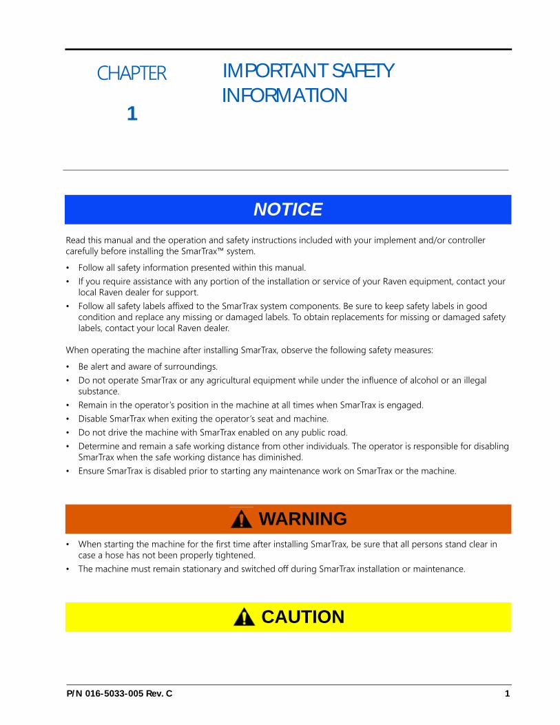
Read this manual and the operation and safety instructions included with your implement and/or controller carefully before installing the SmarTrax™ system.
• Follow all safety information presented within this manual.• If you require assistance with any portion of the installation or service of your Raven equipment, contact your
local Raven dealer for support.• Follow all safety labels affixed to the SmarTrax system components. Be sure to keep safety labels in good
condition and replace any missing or damaged labels. To obtain replacements for missing or damaged safety labels, contact your local Raven dealer.
When operating the machine after installing SmarTrax, observe the following safety measures:
• Be alert and aware of surroundings.• Do not operate SmarTrax or any agricultural equipment while under the influence of alcohol or an illegal
substance.• Remain in the operator’s position in the machine at all times when SmarTrax is engaged.• Disable SmarTrax when exiting the operator’s seat and machine.• Do not drive the machine with SmarTrax enabled on any public road.• Determine and remain a safe working distance from other individuals. The operator is responsible for disabling
SmarTrax when the safe working distance has diminished.• Ensure SmarTrax is disabled prior to starting any maintenance work on SmarTrax or the machine.
• When starting the machine for the first time after installing SmarTrax, be sure that all persons stand clear in case a hose has not been properly tightened.
• The machine must remain stationary and switched off during SmarTrax installation or maintenance.
NOTICE
WARNING
CAUTION
1

CHAPTER 1
HYDRAULIC SAFETY• Raven Industries recommends that appropriate protective equipment be worn at all times when working on the
hydraulic system.• Never attempt to open or work on a hydraulic system with the equipment running. Care should always be
taken when opening a system that has been previously pressurized.• When disconnecting the hydraulic hoses or purging is required, be aware that the hydraulic fluid may be
extremely hot and under high pressure. Caution must be exercised.• Any work performed on the hydraulic system must be done in accordance with the machine manufacturer’s
approved maintenance instructions.• When installing SmarTrax hydraulics or performing diagnostics, maintenance, or routine service, ensure that
precautions are taken to prevent any foreign material or contaminants from being introduced into the machine’s hydraulic system. Objects or materials that are able to bypass the machine’s hydraulic filtration system will reduce performance and possibly damage the SmarTrax valve.
ELECTRICAL SAFETY• Always verify that the power leads are connected to the correct polarity as marked. Reversing the power leads
could cause severe damage to the equipment.• Ensure that the power cable is the last cable to be connected.
2 Massey Ferguson 76X0/86X0/8700 Series, AGCO DT-B Series, and Challenger MT6X5C/D/E Series - Steer-

CHAPTER
2
P/N 016-5033-005 Rev. C
CHAPTER 2INTRODUCTION
Congratulations on your purchase of the SmarTrax system! This system is designed to provide cutting-edge, hands-free steering of the machine via Global Positioning System (GPS) coordinates.
This manual applies to the following machines:
MAKE: AGCOMODEL: DT205B, DT225B, DT250B, and DT275B - Steering ReadyYEAR: 2009-2010
MAKE: Challenger MODEL: MT645E, MT655E, MT665E, MT675E, and MT685E- Steering ReadyYEAR: 2014-2016
MAKE: Challenger MODEL: MT645D, MT655D, MT665D, MT675D, and MT685D- Steering ReadyYEAR: 2011-2013
MAKE: ChallengerMODEL: MT645C, MT655C, MT665C, MT675C, and MT685C - Steering ReadyYEAR: 2009-2010
MAKE: Massey Ferguson MODEL: 8727, 8730, 8732, 8735 and 8737- Steering ReadyYEAR: 2014-2016
MAKE: Massey Ferguson MODEL: 7614, 7615, 7616, 7618, 7619, 7620, 7622, 7624, and 7626 - Steering ReadyYEAR: 2013-2014
MAKE: Massey Ferguson MODEL: 8650, 8660, 8670, 8680, and 8690 - Steering ReadyYEAR: 2009-2013
MAKE: Massey Ferguson MODEL: 8450, 8460, 8470, and 8480 - Steering ReadyYEAR: 2004-2007
3

CHAPTER 2
FIGURE 1. Massey Ferguson 86X0 Series, AGCO DT-B Series, Challenger MT6X5C Series
PREPARING FOR INSTALLATION
Before installing the SmarTrax system, park the machine where the ground is level, clean, and dry. Turn off the machine and leave it turned off for the duration of the installation process. Bleed pressure from the hydraulic system by loosening the hydraulic fittings slowly, where applicable.
During the installation process, follow good safety practices. Be sure to carefully read the instructions in this manual as you complete the installation process.
RECOMMENDATIONS
Raven Industries recommends the following best practices when installing or operating the SmarTrax system for the first time, at the start of the season, or when moving the SmarTrax system to another machine:
• Install the GPS antenna on the front center of the machine’s cab.• Ensure the machine’s hydraulic filters have been recently changed and there are no issues with the machine’s
hydraulic system (e.g., pump issues, faulty hydraulic motors, fine metal deposits in the hydraulic hoses, etc.).• Ensure the machine’s hydraulic valve is using fresh oil and debris is flushed from the hydraulic hoses, valves,
and filters.
Raven Industries recommends the following best practices when installing the SmarTrax system:
• Use part numbers to identify the parts.• Do not remove the plastic wrap from a part until it is necessary for installation.• Do not remove plastic caps from a part until it is necessary for installation.
POINT OF REFERENCE
The instructions in this manual assume that you are standing behind the machine, looking toward the cab.
UPDATES
Software and manual updates are available on the Raven Applied Technology website:
http://www.ravenhelp.com
4 Massey Ferguson 76X0/86X0/8700 Series, AGCO DT-B Series, and Challenger MT6X5C/D/E Series - Steer-

2
INTRODUCTION
KIT CONTENTS
This section contains a list of the components that are included in the SmarTrax kit. Before beginning the SmarTrax installation, compare the items in the kit with the components on this list. If you have questions about the kit, contact your Raven dealer.
At Raven Industries, we strive to make your experience with our products as rewarding aspossible. One way to improve this experience is to provide us with feedback on this manual.
Your feedback will help shape the future of our product documentation and the overall service weprovide. We appreciate the opportunity to see ourselves as our customers see us and are eagerto gather ideas on how we have been helping or how we can do better.
To serve you best, please send an email with the following information to
-Massey Ferguson 76X0/86X0/8700 Series, AGCO DT-B Series, and Challenger MT6X5C/D/ESeries - Steering Ready SmarTrax™ Installation Manual-P/N 016-5033-005 Rev. C-Any comments or feedback (include chapter or page numbers if applicable).-Let us know how long have you been using this or other Raven products.
We will not share your email or any information you provide with anyone else. Your feedback isvalued and extremely important to us.
Thank you for your time.
TABLE 1. SmarTrax Installation Kit (P/N 117-5033-005)
Picture Item Description Part Number Qty.
Not Pictured
Manual - Massey Ferguson 86X0 Series, AGCO DT-B Series, and Challenger MT6X5C Series - Steering Ready SmarTrax Installation
016-5033-005 1
Not Pictured Manual - SmarTrax and SmartSteer Calibration & Operation 016-0171-277 1
Node - SmarTrax RTK 063-0173-228 1
Bracket - Node Mounting 107-0172-055 1
P/N 016-5033-005 Rev. C 5

CHAPTER 2
Cable - Gen II to 3-Pin Power Adapter 115-4001-119 1
Cable - Node Harness 115-4001-142 1
Assembly - Enable Foot Switch 063-0172-470 1
Spacer - 3/8” ID x 3/4” OD x 1” Long 107-0172-038 2
Bolt - 3/8”-16 UNC x 2-1/2” Hex 311-0054-111 2
Nut - 3/8”-16 Nylon Insert Lock 312-4000-061 2
Nut - 3/8”-16 Nylon insert Thin Lock 312-4001-109 3
Washer - 0.406” ID x 0.812” OD x 0.065” Thick 313-2300-014 2
TABLE 2. SmarTrax Installation Kit (P/N 117-5033-009)
Picture Item Description Part Number Qty.
Not Pictured
Manual - Massey Ferguson 86X0 Series, AGCO DT-B Series, and Challenger MT6X5C Series - Steering Ready SmarTrax Installation
016-5033-005 1
Not Pictured Manual - SmarTrax and SmartSteer Calibration & Operation 016-0171-277 1
TABLE 1. SmarTrax Installation Kit (P/N 117-5033-005)
Picture Item Description Part Number Qty.
6 Massey Ferguson 76X0/86X0/8700 Series, AGCO DT-B Series, and Challenger MT6X5C/D/E Series - Steer-

INTRODUCTION
Node - SmarTrax RTK 063-0173-228 1
Bracket - Node Mounting 107-0172-482 1
Cable - Gen II to 3-Pin Power Adapter 115-4001-119 1
Cable - Node Harness 115-4001-239 1
Assembly - Enable Foot Switch 063-0172-470 1
U-Bolt - 1” W x 1-1/4” L x 1/4” Thread 107-0171-102 2
Nut - 1/4”-20 UNC Zinc Flanged Lock 312-1001-168 4
Nut - 3/8”-16 Nylon insert Thin Lock 312-4001-109 3
Tape - Double-Sided 332-0000-019 6
TABLE 2. SmarTrax Installation Kit (P/N 117-5033-009)
Picture Item Description Part Number Qty.
P/N 016-5033-005 Rev. C 7

CHAPTER 2
8 Massey Ferguson 76X0/86X0/8700 Series, AGCO DT-B Series, and Challenger MT6X5C/D/E Series - Steer-

CHAPTER
3
P/N 016-5033-005 Rev. C
CHAPTER 3CAB COMPONENT INSTALLATION
INSTALL THE SMARTRAX NODE
MOUNT THE SMARTRAX NODE - KIT 117-5033-005
FIGURE 1. Node Mounting Bracket Placed on Cab Floor
1. Place the node mounting bracket (P/N 107-0172-055) on the floor of the cab to the left of the operator’s seat.
NOTE: Position the bracket as close to the seat and as far back as possible in the cab, while ensuring the bracket is remains on the flat portion of the floor mat. Verify there is no interference from the cab suspension below the floor.
2. Using the holes in the node mounting bracket as a guide, drill two holes through the floor mat into the cab floor using a 13/32” drill bit.
3. Remove the node mounting bracket.4. Enlarge the holes in the cab floor with a 3/4” drill bit.5. Place 3/8” ID x 3/4” OD x 1” long spacers (P/N 107-0172-038) in each hole in the floor mat.
9

CHAPTER 3
FIGURE 2. Node Mounting Bracket Installed
6. Align and place the node mounting bracket on the spacers.7. Insert two 3/8”-16 UNC x 2-1/2” hex bolts (P/N 311-0054-111) through the holes in the node mounting bracket.
NOTE: The bolts must be installed pointing toward the ground to avoid damage to the node when installed.
8. Secure the bracket by installing two washers (P/N 313-2300-014) and two 3/8”-16 nylon insert lock nuts(P/N 312-4000-061) on the bolts under the cab.
FIGURE 3. Node Installed
9. Install the node (P/N 063-0173-228) on the mounting bracket using three 3/8”-16 nylon insert thin lock nuts (P/N 312-4001-109).
MOUNT THE SMARTRAX NODE - KIT 117-5033-0091. Mount the node mounting bracket (P/N 107-0172-482) on the bar running along the front of the cab using two
3/4” W x 1-1/4” L x 1/4”-20 thread U-bolts and four 1/4”-20 flanged lock nuts.
10Massey Ferguson 76X0/86X0/8700 Series, AGCO DT-B Series, and Challenger MT6X5C/D/E Series - Steer-

3
CAB COMPONENT INSTALLATION
FIGURE 4. Node Mounting Bracket and Support Bracket Installed
2. Install the two large, rectangular connectors of the node harness (P/N 115-4001-239) into the correct ports of the node.
3. Tighten the bolts on the harness connectors to secure the connections.4. Mount the node on the node mounting bracket using three 3/8”-16 nylon insert thin lock nuts.
FIGURE 5. Node Installed
5. Route the node harness along the floor mat and under the access panel to the right of the operator’s seat.
P/N 016-5033-005 Rev. C 11

CHAPTER 3
FIGURE 6. Access Panel Location
NODE MOUNTING LOCATIONS
FIGURE 7. Node Mounting
When choosing the location for the SmarTrax node, consider the following points:
• Mount the SmarTrax node inside the machine’s cab on a flat, level surface for proper performance and cable connection.
• One of the six numbered direction arrows on the node must be oriented in the direction of forward vehicle travel, one arrow pointing straight up, and two of the arrows parallel to the ground.
NOTE: Make a note of the number of the arrow that is oriented in the direction of forward vehicle travel. This number will be needed during the SmarTrax calibration process.
• The node mounting location must not create tripping hazards.• Mount the node in a location where it will not be kicked or jarred during normal equipment operation.• The location must allow cable routing to avoid crimping or damaging the cables or the node connections.• Securely fasten the node using bolts or screws through at least two of the three mounting holes. When
mounted properly, the node should not become loose or rotate.
Direction Arrows
Any two arrows must be parallel with level ground
Mounting Tabs
1
2
3
4
5
12Massey Ferguson 76X0/86X0/8700 Series, AGCO DT-B Series, and Challenger MT6X5C/D/E Series - Steer-

3
CAB COMPONENT INSTALLATION
INSTALL THE NODE HARNESS
FIGURE 8. Cab Post Cover
1. Remove the post cover and fuse box cover in the right-rear corner of the cab.2. Remove the screws used to fasten the plastic panel surrounding the fuse box.
NOTE: It is not necessary to remove the panel.
FIGURE 9. Machine’s 12-Pin Harness Connection - Kit 117-5033-005
P/N 016-5033-005 Rev. C 13

CHAPTER 3
FIGURE 10. Machine’s 12-Pin Harness Connection - Kit 117-5033-009
3. Locate and disconnect the machine’s 12-pin connector labeled “X282” on the cab post.
FIGURE 11. Node Harness Routed to Machine Harness
4. Route the 12-pin tee connectors of the node harness (P/N 115-4001-142) through the panel below the fuse box and toward the X282 connector on the post.
14Massey Ferguson 76X0/86X0/8700 Series, AGCO DT-B Series, and Challenger MT6X5C/D/E Series - Steer-

3
CAB COMPONENT INSTALLATION
FIGURE 12. Node Harness Connected to Machine Harness
5. Connect the 12-pin connectors to the X282 connectors of the machine’s harness.
FIGURE 13. Node Harness Connected to Node
6. Install the two large, rectangular connectors of the node harness into the correct ports of the node, tightening the bolts on the connectors to secure the connections.
7. Route any GPS cable connectors down the cab post.8. Reinstall the post and fuse box covers.
P/N 016-5033-005 Rev. C 15

CHAPTER 3
INSTALL THE FOOT SWITCH
FIGURE 14. Foot Switch Installed
1. Select a suitable location for the foot switch (P/N 063-0172-470) to be installed.
NOTE: The foot switch should be installed in a location where the operator has easy access to it and is able to fully press the pedal.
2. Using the holes in the foot switch as a template, drill holes in the floor of the cab.3. Secure the foot switch to the floor by installing the supplied screws in each of the mounting holes.4. Locate the ENABLE connector of the node harness (P/N 115-4001-142) and connect it to the foot switch cable
connector.
INSTALL THE POWER ADAPTER CABLE
FIGURE 15. Power Adapter Cable Connected to Node Harness
1. Connect the round 16-pin connector of the power adapter cable (P/N 115-4001-119) to the mating connector of the node harness (P/N 115-4001-142).
16Massey Ferguson 76X0/86X0/8700 Series, AGCO DT-B Series, and Challenger MT6X5C/D/E Series - Steer-

3
CAB COMPONENT INSTALLATION
FIGURE 16. Power Adapter Cable Connected to Power Port
2. Connect the power adapter cable to the power port on the right-rear cab post or near the right cab window.3. Install a terminator (P/N 063-0172-369) on the CAN cable connector.
P/N 016-5033-005 Rev. C 17

CHAPTER 3
FIGURE 17. Node Harness Installation
18Massey Ferguson 76X0/86X0/8700 Series, AGCO DT-B Series, and Challenger MT6X5C/D/E Series - Steer-

3
CAB COMPONENT INSTALLATION
CONNECT THE SMARTRAX SYSTEM TO AN EXISTING CHASSIS CABLE (IF APPLICABLE)1. Locate and disconnect the connection between the Raven console cable and chassis cable on the machine’s
existing CAN system.2. Install the node harness (P/N 115-4001-142) between the chassis and Raven console harness.
P/N 016-5033-005 Rev. C 19
CHAPTER 3
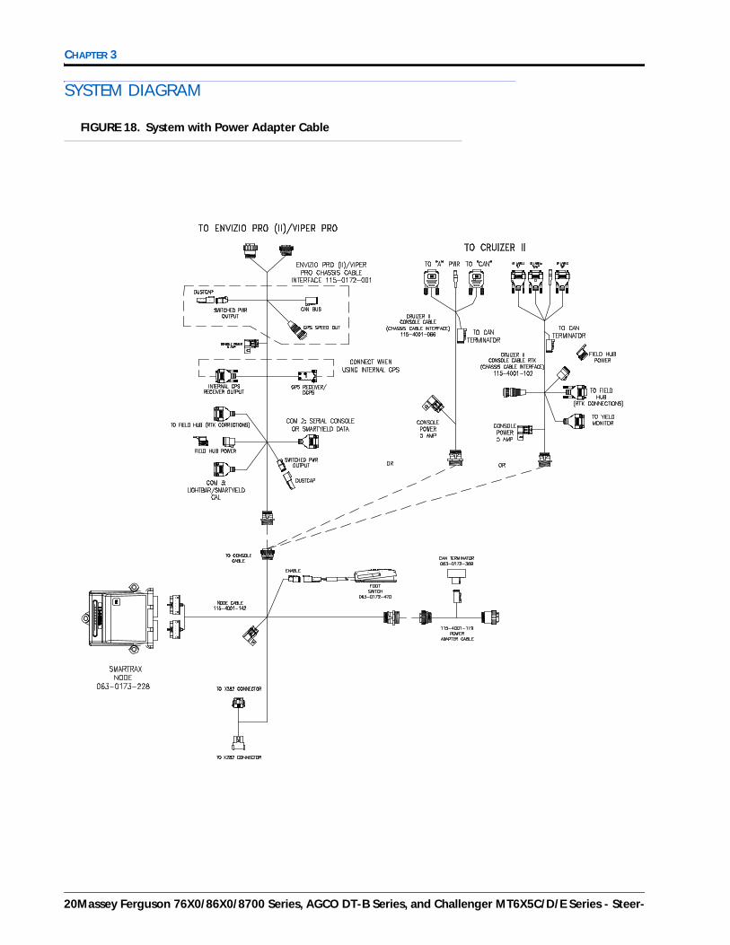
SYSTEM DIAGRAM
FIGURE 18. System with Power Adapter Cable
20Massey Ferguson 76X0/86X0/8700 Series, AGCO DT-B Series, and Challenger MT6X5C/D/E Series - Steer-

3
CAB COMPONENT INSTALLATION
FIGURE 19. Existing Chassis System Wiring Diagram
P/N 016-5033-005 Rev. C 21

CHAPTER 3
FIGURE 20. Envizio Pro II with Slingshot
22Massey Ferguson 76X0/86X0/8700 Series, AGCO DT-B Series, and Challenger MT6X5C/D/E Series - Steer-

CAB COMPONENT INSTALLATION
FIGURE 21. Viper Pro/Envizio Pro with Slingshot
P/N 016-5033-005 Rev. C 23

CHAPTER 3
FIGURE 22. Cruizer II with Slingshot
24Massey Ferguson 76X0/86X0/8700 Series, AGCO DT-B Series, and Challenger MT6X5C/D/E Series - Steer-
CHAPTER
4
P/N 016-5033-005 Rev. C
CHAPTER 4STARTUP PROCEDURES
CALIBRATE THE SMARTRAX SYSTEM
Refer to the SmarTrax & SmartSteer Calibration and Operation Manual (P/N 016-0171-277) for instructions on calibrating the SmarTrax system, adjusting system settings, and system operation.
ENGAGE THE TRACTOR’S STEERING SYSTEM
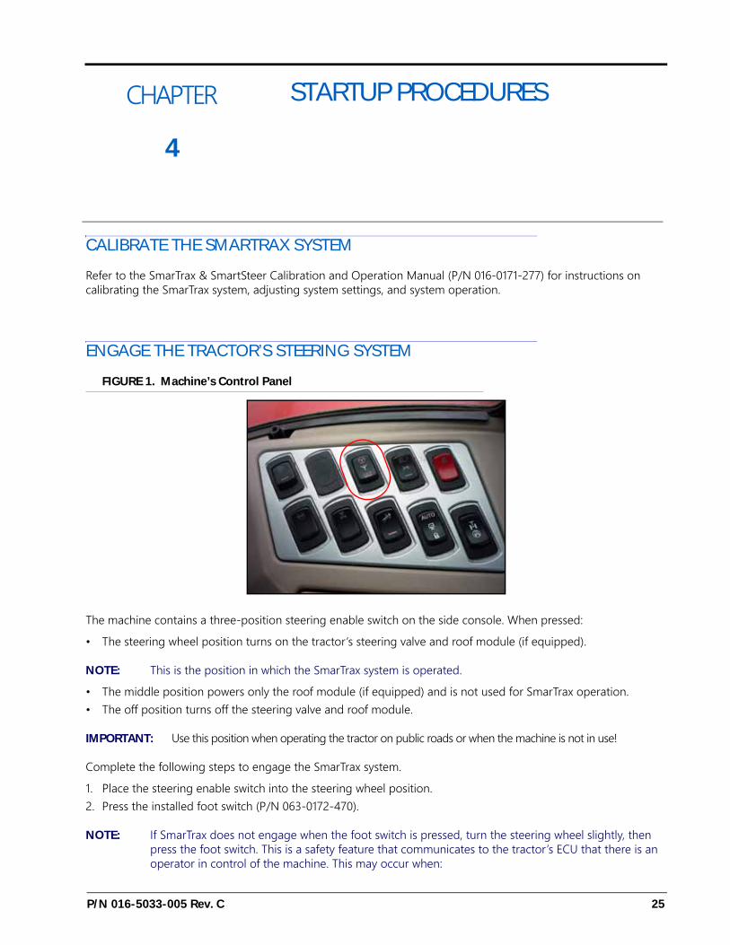
FIGURE 1. Machine’s Control Panel
The machine contains a three-position steering enable switch on the side console. When pressed:
• The steering wheel position turns on the tractor’s steering valve and roof module (if equipped).
NOTE: This is the position in which the SmarTrax system is operated.
• The middle position powers only the roof module (if equipped) and is not used for SmarTrax operation.• The off position turns off the steering valve and roof module.
IMPORTANT: Use this position when operating the tractor on public roads or when the machine is not in use!
Complete the following steps to engage the SmarTrax system.
1. Place the steering enable switch into the steering wheel position.2. Press the installed foot switch (P/N 063-0172-470).
NOTE: If SmarTrax does not engage when the foot switch is pressed, turn the steering wheel slightly, then press the foot switch. This is a safety feature that communicates to the tractor’s ECU that there is an operator in control of the machine. This may occur when:
25

CHAPTER 4
• The first time SmarTrax is engaged after powering on the steering valve.• The system is disengaged using the foot switch rather than by turning the steering wheel.• The system is disengaged using the Steering icon on the field computer rather than by turning the steering
wheel.
26Massey Ferguson 76X0/86X0/8700 Series, AGCO DT-B Series, and Challenger MT6X5C/D/E Series - Steer-

4
STARTUP PROCEDURES
P/N 016-5033-005 Rev. C 27

CHAPTER 4
28Massey Ferguson 76X0/86X0/8700 Series, AGCO DT-B Series, and Challenger MT6X5C/D/E Series - Steer-

Index
CCab Component Installation
Connecting the SmarTrax System to an Existing Chassis Cable 19
Installing the Foot Switch 16Installing the Node Harness 13Installing the Power Adapter Cable 16Installing the SmarTrax Node 9
Mounting the Node - Kit 117-5033-005 9Mounting the Node - Kit 117-5033-009 10Node Mounting Locations 12
System Diagrams 20
IImportant Safety Information
Electrical Safety 2Hydraulic Safety 2
IntroductionKit Contents 5Preparing for Installation 4
Point of Reference 4Recommendations 4
KKit Contents 5
SStartup Procedures
Calibrating the SmarTrax System 25Engaging the SmarTrax System 25
P/N 016-5033-005 Rev. C 29

Index
30Massey Ferguson 76X0/86X0/8700 Series, AGCO DT-B Series, and Challenger MT6X5C/D/E Series - Steer-

Raven Industries will not assume any expense or liability for repairs made outside our facilities without written consent. Raven Industries is not responsible for damage to any associated equipment or products and will not be liable for loss of profit, labor, or other damages. The obligation of this warranty is in lieu of all other warranties, expressed or implied, and no person or organization is
authorized to assume any liability for Raven Industries.
Damages caused by normal wear and tear, misuse, abuse, neglect, accident, or improper installation and maintenance are
not covered by this warranty.
What is not Covered by this Warranty?
Upon confirmation of the warranty claim, Raven Industries will (at our discretion) repair or replace the defective product and pay for the standard return freight, regardless of the inbound shipping method.
Expedited freight is available at the customer’s expense.
What Will Raven Industries Do?
Bring the defective part and proof of purchase to your Raven dealer.If the dealer approves the warranty claim, the dealer will process the claim and send it to Raven Industries for final approval. The freight cost to Raven Industries will be the customer’s responsibility. The Return Materials Authorization (RMA) number must appear on the box and all documentation (including proof of purchase) must be included inside
the box to be sent to Raven Industries.
How Can I Get Service?
Raven Applied Technology products are covered by this warranty for 12 months from the date of retail sale. In no case will the Limited Warranty period exceed 24 months from the date the product was issued by Raven Industries Applied Technology Division. This warranty coverage
applies only to the original owner and is non-transferable.
How Long is the Coverage Period?
This warranty covers all defects in workmanship or materials in your Raven Applied Technology Division product under normal use,
maintenance, and service when used for intended purpose.
What Does this Warranty Cover?
Limited Warranty
016-0171-537 Rev. A, E19889

Raven Applied Technology products that have been registered online are covered for an additional 12 months beyond the Limited Warranty for a total coverage period of 24 months from the date of retail sale. In no case will the Extended Warranty period exceed 36 months from the date the product was issued by Raven Industries Applied Technology Division. This Extended Warranty coverage applies only to the
original owner and is non-transferable.
How Long is the Extended Warranty Coverage Period?
To register, go online to www.ravenhelp.com and select Product Registration.Where Can I Register My Product for the Extended Warranty?
Yes. Products/systems must be registered within 30 days of retail sale to receive coverage under the Extended Warranty. If the component does not have a serial
tag, the kit it came in must be registered instead.
Do I Need to Register My Product to Qualify for the Extended Warranty?
This warranty covers all defects in workmanship or materials in your Raven Applied Technology Division product under normal use, maintenance, and service when
used for intended purpose.
What Does this Warranty Cover?
Bring the defective part and proof of purchase to your Raven dealer. If the dealer approves the warranty claim, the dealer will process the claim and send it to Raven Industries for final approval. The freight cost to Raven Industries will be the customer’s responsibility. The Return Materials Authorization (RMA) number must appear on the box and all documentation (including proof of purchase) must be included inside the box to be sent to Raven Industries. In addition, the words “Extended Warranty” must appear on the box and all documentation if the failure is
between 12 and 24 months from the retail sale.
How Can I Get Service?
Upon confirmation of the product’s registration for the Extended Warranty and the claim itself, Raven Industries will (at our discretion) repair or replace the defective product and pay for the standard return freight, regardless of the inbound shipping
method. Expedited freight is available at the customer’s expense.
What Will Raven Industries Do?
Raven Industries will not assume any expense or liability for repairs made outside our facilities without written consent. Raven Industries is not responsible for damage to any associated equipment or products and will not be liable for loss of profit, labor, or other damages. Cables, hoses, software enhancements, and remanufactured items are not covered by this Extended Warranty. The obligation of this warranty is in lieu of all other warranties, expressed or implied, and no person
or organization is authorized to assume any liability for Raven Industries.
Damages caused by normal wear and tear, misuse, abuse, neglect, accident, or improper installation and maintenance are not covered by this warranty.
What is Not Covered by the Extended Warranty?
Extended Warranty
016-0171-536 Rev. A, E19889