Embed Size (px)
Citation preview
MASS FABRICATION OF HEAVY STEEL COLUMNS
. by
Lambert Tall
Pavel J. Marek
Paper Prepared for the IABSE Symposium on Mass-Produced Structures, Prague, Czechoslovakia, September 1971.
May 1971
Fritz Laboratory Report No. 337.30

, 1
Discussion Prepared for
IABSE SYMPOSIUM
Prague, September 1971
MASS FABRICATION OF HEAVY STEEL COLUMNS
Lambert Tall
U.S.A.
by
. Pavel J. Marek
Czechoslovakia
Dr. Lambert Tall is Professor of Civil Engineering, and Director, Division for Fatigue and Fracture, Lehigh University, Bethlehem, Pennsylvania, U.S.A.
Dr. Pavel J. Marek is Associate Professor, SF CVUT, Chair for Steel Structures, Prague, Czechoslovakia, and formerly Research Associate at Lehigh
. University, Bethlehem, Pennsylvania, U.S.A.

TABLE OF CONTENTS
INTRODUCTION
COLUMN STRENGTH AND FABRICATION METHOD
ROLLED SHAPES
WELDED SHAPES
MISCELLANEOUS INFORMATION ON MANUFACTURING PROCEDURES
REPRODUCIBILITY OF COLUMN STRENGTH
CONCLUSIONS
ACKNOWLEDGEMENTS
REFERENCES
ABSTRACT
FIGURES
1
2
2
3
4
5
5
5
5
6
7

-1
INTRODUCTION
In today's large structures, increasingly heavy steel elements are being used. The buildings have grown taller, resulting in substantially higher axial forces in vertical members due to dead, live, and wind loads. In the case of the quite common unbraced frames, the steel columns are subjected also to high bending moments, which have significant influence on their design. The selection of the cross sections must be carried out by the designer, not only with respect to the required carrying-capacity, but also taking into account the economical considerations which depend to a large extent on the fabrication procedure.
In the case of very heavy columns for the lower floors of a multistory building, for example, the fabrication may be considered as essentially "one-off n or unique. On the other hand, the high number of medium-heavy columns used in other parts of the structure are mass-produced by being fabricated in automated or semiautomated production lines. Special skills have been developed in the area of rolling and welding of columns with respect to a high number of similar shapes.
A recent survey of the utilization and manufacture of heavy columns [1] has indicated that the two types most commonly used are wide-flange and H-shapes. Box-sections also seem to have some importance, whereas all other types are used to a rel~tively small extent. with respect to mass fabrication then, the main attention should be given to the rolled and welded wide-flange and H-shaped medium-heavy columns. The range of dimensions· of these shapes is shown in Fig. 1.
In this discussion, brief mention is given to medium-heavy steel columns, to the correlation of column strength with the fabrication procedures by automated processes, and to the reproducibility of the strength of such members.

• <
-2
COLUMN STRENGTH AND THE FABRICATION METHOD
Residual stresses and the initial out-of-straightness are the predominant factors affecting the strength of a steel column and are directly dependent on the fabrication method. [2]
The initial crookedness of the column is checked after the rolling or welding phase is completed. Straightening by coldbending is usually necessary and is the next step. The residual stresses are formed mainly during cooling after rolling; a redis~ tribution of the residual stresses may take place due to flamecutting, welding, heat-treatment or cold-straightening. It would be possible to modify, or even to remove completely, residual stresses from the column - for example by stress relieving - but this is not the normal practice because of economical reasons.
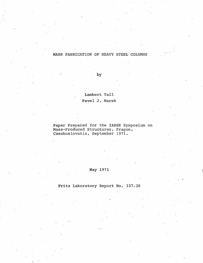
The difference between the strength of rolled wide-flange shapes and the strength of welded shapes (built-up from flame-cut plates or universal mill plates) is illustrated in Fig. 2 for some particular sections. [3]
The present trend in the evaluation of column strength recognizes the significance of the different fabrication procedures, by introducing more than one column curve for design. [4,5] This trend should be taken into account for optimum results in the use of automated processes for mass production of steel columns.
ROLLED SHAPES
The rolling technique is highly developed and allows rolling of shapes up to about 750 lb./ft., Fig. 3. [6]
The material enters the mill in th~ form of a rectangular cross section and is then rolled in a number of passes in two or more rolling stands. The cross section is gradually reduced until the shape has reached its final cross section in the finishing stand. After rolling, the material is cut at the hot saw to the required length and allowed to cool down on a cooling bed. It is only after this mainly automated phase that the shape may . require individual care. Due to uneven pooling conditions many members are crooked, and so, most shapes have to be straightened, either by roller-straightener or in a gag press.
In the roller straightener the member is passed through a number of rolls which bend the shape in alternating directions. This is essentially a continuous process, affecting the whole length and modifying the residual stress distribution and therefore the strength as well. The resulting residual stresses are relatively constant in magnitude along the length.
The roller-straighteners used today have a limited capacity and heavier shapes usually must be straightened in a gag press. In the gagging procedure, only local parts of the shape are

-3
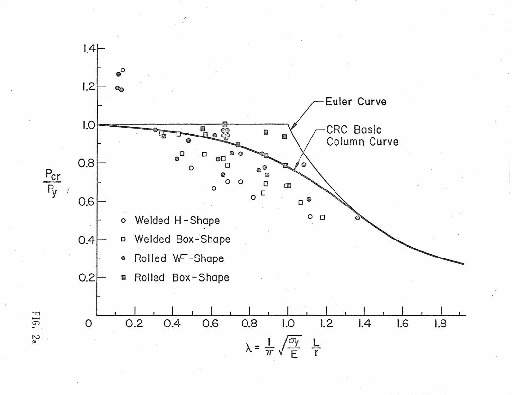
affected. Thus, the residual stresses are changed only at certain sections along the length. Figure 4 shows the nonsymetrical residual stress distribution in the shape Wl4x730 where two types of residual stresses were coexisting, thermal stresses and stresses due to gagging; [6] gagging has affected only one side of the flanges.
It should be noted that for the heaviest shapes rolled at present, it is difficult to keep the deviations of cross-sectional geometry within the specified tolerances.
WELDED SHAPES
The welded H-shapes are built-up from component plates. The plates are manufactured either as universal mill plates (UM) rolled to exact width and used with as-rolled edges (Fig. 5), or wide plates are first flame-cut to the required width, and these are called flame-cut plates (FC). The significant difference between the residual stresses in UM and FC plates due to the fabrication is that pointed out in the above discussion on the column strength; that is, the original residual stresses due to cooling are modified drastically by the introduction of the heat input of flame-cutting. In general, the use of flame-cut plates improves column strength. [7] For medium-heavy shapes, welded from UM plates, the residual stresses are not affected significantly by the weld; thus, the strength of such columns compares directly to that of rolled shapes, discussed above.
A fully automatic manufacturing procedure for H-shapes is described next. [7] (Again, the fabrication procedure affects the column strength directly.) The procedure described is in quite common use.
a. Wide plates are first "stripped" - flame-cut by automatic equipment as shown in Fig. 6 to the required width for use as webs and flanges.
b. Flange plates thinner than 3/4 in. are placed in a "crimper", which pre-bows them so that the flanges are flat after welding. This is not necessary for thick flange plates -- indeed, it may be impossible.
c. Two flanges and a web are then placed on a "fit-upll table. A hydraulically operated II fit-up" gate shown in Fig. 7 is used at the head end of the plates to position the plates.
d. The plates are tack-welded at the head end only and moved to the first welding unit, Fig. 8. Here, the plates are preheated with torches and the two fillets on one side of the web are deposited by continuous submerged-arc welding in one pass.
e. On the exit table from the first welding unit the shape is lifted by a movable fork lift, turned over, and placed on the entry table of the second welding unit, Fig. 9.

, .
-4
f. The remaining two fillet welds are deposited.
g. The section is oxygen-cut at each end to the correct length, Fig. 10.
h. The final step in manufacturing takes place at the inspection and conditioning skids where any needed minor repair welding is done, Fig. 11.
MISCELLANEOUS INFORMATION ON MANUFACTURING PROCEDURES
One phase of a continuing study of residual stresses and column strength of rolled and welded steel shapes carried out at Lehigh University during past two decades was focused on the manufacture and fabrication of heavy and medium-heavy columns. [1,.8] Following are some of conclusions resulting mainly from the survey and aimed at various problems involved in the fabrication process:
Welding Methods: The data available from fabricators in the'USA indicate that the automatic submerged arc method is the most common. (1790) However, the use of other methods such as MIG was reported, and almost exclusively by the large fabricators. Some fabricators are employing combinations of two or more regular techniques. The gas-shielded methds seem mostly to be applied for small-scale work.
Welding Types: For welding together column component plates, mainly fillet welds are used except for box sections and some special sections, where the welds are of partial penetration single or double bevel-groove type.
preheating and postheating: The procedure used for heat treatment of welded assemblies, when such is required either by contract or specifications, is that given in AWS's'''Code for Welding in Building Construction". Post-heating was not reported in any of the projects in the survey.
Straightening: The allowable limits of distortion or of out-ofstraightness are specified by various codes and specifications. Considerable deformations normally may occur during welding. The distortions sometimes cause severe problems for proper erection of the structure, emphasizing the need of proper straightening. Besides roller and gag straightening, heat-straightening is performed sometimes.
Testing of Welds: Ultrasonic testing seems to be the most common method for weld tests in the case of heavy columns, followed by X-Ray tests and magnetic particle testing (for surface cracks) .

-5
REPRODUCIBILITY OF THE COLUMN STRENGTH
The scatter in the column strength is related to several variables. The reproducibility of the strength depends mainly on the constancy of the yield strength, out-of-straightness and residual stresses. The last two items relate directly to the production techniques, and their constancy. Extensive research programs have been underway at Lehigh University and elsewhere in the area of the statistical and probabilistic evaluation of individual variables, their significance and interaction, [4,9] in order to categorize the shapes and to propose column design curves representing, as closely as 'possible, the actual carrying capacities of various manufactured shapes. This will be important for the fUrther technical and economical development of automated processes for the mass production of steel columns.
CONCLUSIONS
. The mass fabrication of medium-heavy steel columns has been described briefly in this paper. An example was given of an automated process for the preparation of the commonly used wideflange and H-shapes. The relationship between the fabrication procedure, the strength, and its reproducibility, ,were considered.
ACKNOWLEDGEMENTS
This paper presents the results of a long-term study into the column strength of structural steel members, underway at Fritz Engineering Laboratory, Lehigh University, Bethlehem, Pennsylvania. The Amer~can Institute of Steel Construction and the (U.S.) National Science Foundation sponsored those parts of
<, the study referred to in this paper.
. REFERENCES
1. Bj¢rhovde, R. and Tall, L. SURVEY OF UTILIZATION AND MANUFACTURE OF HEAVY COLUMNS, Fritz Laboratory Report No. 337.7, October 1970.
2. Beedle,L. S. and Tall, L. BASIC COLUMN STRENGTH, Journal of the Structural Division, Proceedings ASCE 2555, Vol. 86, ST7, July 1960.
3. Tall, L. and Alpsten, G. A. PREDICTION OF BEHAVIOR OF STEEL COLUMNS UNDER LOAD, IABSE Symposium on Safety - London 1969.

-6
4. Beer, H. ind Schulz, G. DIE TRAGLAST DES PLANMASIG MITTIG GEDRUCKTEN STABS MIT IMPERFEKTIONEN, VDI - Z, No. 21, November, 1969.
5. Johnston, B. G., Editor Column Research Council's GUIDE TO DESIGN CRITERIA FOR METAL COMPRESSION MEMBERS, 3rd. Ed., Wiley, to be published in 1972.
6. Brozzetti, J., Alpsten, G. A. and" Tall, L. RESIDUAL STRESSES IN A HEAVY ROLLED SHAPE, Fritz Laboratory Report No. 337.10, January 1970.
7. McFalls, R. K. and Tall, L. A STUDY OF WELDED COLUMNS MANUFACTURED FROM FLAMECUT PLATES, Welding Journal, Vol. 48, April 1969.
8. Brozzetti, J., Alpsten, G. A. and Tall, L. MANUFACTURE AND FABRICATION OF HEAVY WELDED PLATE AND SHAPE SPECIMENS, Fritz Laboratory Report No. 337.4, May 1969.
9. Tall, L. and Alpsten, G. A. ON THE SCATTER IN YIELD STRENGTH AND RESIDUAL STRESSES IN STEEL MEMBERS, IABSE Symposium on Safety, London, 1969.
ABSTRACT
Heavy steel columns are being used increasingly in many structures. The mass fabrication of such columns is described, and one example is given for welded shapes. The relationship between fabrication procedure, column strength, "and its reproducibility are considered.

. ,
FIGURES
Fig. 1 Dimensions of Heavy Column Shapes
Fig. 2 (a) Column Test Results for Rolled and Welded Shapes
(b) Column Strength of Welded H-Shapes of Flame-Cut and Universal-Mill Plates
Fig. 3 Dimensions of Heavy Rolled Shape W14x730
Fig. 4 Residual Stress Distribution in W14x730 Shape
Fig. 5 The Rolling of Thick, Heavy Plates. (Courtesy Bethlehem Steel Company)
Fig. 6 Automatic Flame-Cutting (Courtesy Inland Steel Company)
Fig. 7 Fitting Flanges and Web (Courtesy. Inland Steel Company)
Fig. 8 Entering First Welding Unit (Courtesy Inland Steel Company)
Fig. 9 Entering Second Welding Unit (Courtesy Inland Steel Company)
Fig. 10 Flame-Cutting to Length (Courtesy Inland Steel Company)
Fig. 11 Inspection Skids (Courtesy Inland Steel Company)

I I ROLLED WIDE-FLANGE
All Sizes Up to and Including WI4x 730
Common Steel Grade: A 36
I J
~ WELDED H
t 20":s H:s 43"
H lO" < B < 40 II - -~II < t < 6 ~ II _ 1- 2
3~ II '.( t < 6 If II ~ - 2 - 2
1- B ~ Common Steel Grade: A 36 (Also Used = A441, A 572)
FIG. 1
11 -en
N PI
Per Py ....
1.4
.0
1.2~· ..
II , 1.0 1 Ill.... m I
~ 0 0 00
0.8 GO • 0
° • ° 0
0.6
o Welded H -Shape
0.4r- 0 Welded Box"';Shape
.. Rolled V'F -Shape
o. 2~ II Rolled Box - Shape
0
II
G~ 6 0 CD
0 0
De
o 0
CRC Basic Column Curve
o 0.2 0.4 0.6 0.8 1.0 1.2
A= _I ja-y h 1T E r
1.4 1.6 1.8

11 ........ G'> -N b"'
T.M. Predicted, Flame -Cut Plates (FC)
. 1.0' \
Per' 0.5 Py
o
'" 0 ............... ................ o
................ o
Universa I }M.S. Pred. Mill Plates (UM) T.M. Pred.
ASTM A36
-H I
0.5
o .................
UM 0
0
""""'0 .......... ......... -.....-.....
FC c 7H28 Em 10H 62 JJ1 12H 79 JfI 14H 202 I
1.0
A = -' jo-y . .b. 7T E r
1.5

1- 18 II -1
~ I r
I 5" I ,
- '~I-"
I
I , WI4x730
- I f31.q." - r-A36
I 21 ,
3" t-I --
l
-5"
.. I
t • - -
WI4x730 ksi
'/


FIG I 6
FIG. 7

FIG. 8
FIG I 9

FIG 10
FIG. 11