Embed Size (px)
Citation preview

1
Mash Tun / RIMS Tube Controller

2
Your new mash tun / RIMS Tube controller Thanks for buying your controller from us!!! Your controller is
based on the MYPIN TA4 series PID controller. Unlike cheap REX
branded controllers, MYPIN controllers are manufactured in China
using modern Surface Mount technology. This is the same
technology used to manufacture your high quality cell phone.
Controller safety We use only aluminum housings for our controllers. We could save
$10 to $30 per controller by switching to plastic housings. But we
want to make sure if the unthinkable happens, that if your
controller were to fail, all of the energy is safely contained inside
your controller housing. We can't make that guarantee with a
plastic housing and neither can anyone else with a plastic housing.
Under the wrong conditions a plastic housing could melt down,
catch on fire and burn your house down!
All of our controllers have been tested behind GFCI and are GFCI
compliant. We highly recommend that you run your controller on a
GFCI protected circuit. But even with GFCI you are mashing with
live power and it takes very little current to kill, so please follow
these basic safety rules.
1. Never brew standing in water or in the rain.
2. Never plug in or unplug your heater or pump with the
power on.
3. Never brew with a known electrical problem.
4. Never touch any nearby metal object when touching your
brew equipment.
5. Never leave your brewery on & unattended.
6. STOP and investigate if you smell something “electrical”, or
feel a shock from your equipment.

3
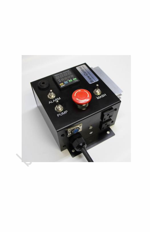
Getting familiar with your new controller Your new controller has six features on the front panel.
A high temperature alarm (top, left corner).
A toggle switch that turns the high temperature alarm on/off (right
below the alarm).
A red mushroom button serves as a main on/on switch as well as a
panic stop button (center, bottom).
A pump on/off switch – operates independent of the mash on/off
switch
A mash on/off switch - operates independent of pump on/off
switch
A MYPIN TA4 series controller that manages your mash
temperature.
4
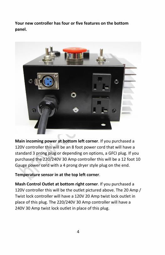
Your new controller has four or five features on the bottom
panel.
Main incoming power at bottom left corner. If you purchased a
120V controller this will be an 8 foot power cord that will have a
standard 3 prong plug or depending on options, a GFCI plug. If you
purchased the 220/240V 30 Amp controller this will be a 12 foot 10
Gauge power cord with a 4 prong dryer style plug on the end.
Temperature sensor in at the top left corner.
Mash Control Outlet at bottom right corner. If you purchased a
120V controller this will be the outlet pictured above. The 20 Amp /
Twist lock controller will have a 120V 20 Amp twist lock outlet in
place of this plug. The 220/240V 30 Amp controller will have a
240V 30 Amp twist lock outlet in place of this plug.
5
Pump Control Outlet at top right corner. Any 120V pump drawing
up to 3 Amps can be plugged into this outlet. We recommend
MARCH pumps because we have had great success with them.
Warning – Do not attempt to plug a second heating element into
the pump outlet. Doing so will damage your controller and void
your warranty!
Optional Flow Control Socket in center of panel. If you purchased
a controller with the flow control option, your flow control switch
plugs into this socket. The socket is designed to accept a 3.5mm
(1/8”) audio jack with your flow control switch wired across the tip
and first ring. We offer a RIMS tube pre-wired with integral flow
control and the correct jack. If you decide to design your own or
buy someone else’s flow control module, your flow control switch
must be configured so that the switch is closed (or on) when you
have flow and open (or off) when flow stopped.
Note: If you plug nothing into this socket your controller will
operate without flow control.
Controller Power Options If you purchased the 120V standard version your controller has an
8’ power cord with a standard 3 prong power plug as well as two
standard 3 prong 15/20 Amp outlets. This controller can safely
manage a heating element as large as 2200 Watts, providing the
outlet you plug the controller into will safely handle the load.
If you purchased the 120V version with GFCI plug your controller
has an 8’ power cord with a GFCI 3 prong power plug as well as two
standard 3 prong 15 Amp outlets. This controller is limited to a
heating element no larger than 1800 Watts because the GFCI plug
itself is only rated for 15 AMPS (1800 watts). If you plan to run a
pump the combined load can be no greater than 1800 watts Just
like the other two 120V controllers, this controller will work with all

6
of our 120V RIMS tubes because we use 1650 WATT heating
elements in all of our 120V RIMS tubes.
If you purchased the 120V twist lock version your controller has an
8’ power cord with a standard 3 prong power plug, a 20 Amp twist
lock style L5-20R heating element outlet and a 3 prong 15 Amp
pump outlet. This controller is designed to operate any element
pre-wired with a L5-20P 120V 20 Amp twist lock plug similar to the
plug used on Blichmann’s 120V BoilCoil. This controller can safely
manage a heating element as large as 2200 Watts, providing the
outlet you plug the controller into will safely handle the load.
Note: Most kitchen circuits installed since the mid 1970’s can safely
handle 20 Amps / 2400 Watts providing nothing else plugged into
the circuit is turned on at the same time. Most kitchen circuits
installed before the mid 1970’s can only safely handle 15 Amps /
1800 Watts providing nothing else plugged into the circuit is turned
on at the same time.
If you purchased the 240V version your controller has a 12’ 10
gauge heavy duty power cord. To be able to support a 240V
element and a 120V pump and be GFCI compliant your controller
will have a 4 prong “dryer plug”. All 240V models ship with a
standard 3 prong twist lock 30 Amp rated power socket and a 3
prong 120 Volt 15 Amp pump outlet. This controller can safely
manage a heating element as large as 6000 Watts.
All units come with a 304 stainless steel water tight PT-100 RTD
temperature probe with 1/2” MPT type threads.
A note on pumps: A 809 series March Pump draws 1.5 Amps (180
Watts) and you should factor in this wattage when planning your
RIMS set-up. Also, all electric motors draw surge current of up to
6X their running current when starting. We include separate
pump and mash switches so that you can to start your pump first

7
then start your PID controller, eliminating any effect the surge
current might have on your mash cycle.
MYPIN Controller Features
Top Row – Displays the current temperature Second Row – Displays the set temperature (the temperature you want to regulate to Out1 – Is on - red when the element is on & off when the element is off Out2/AL2 – Not used in our application AL1 – Turns on when AL1 value is crossed. If you use the temperature alarm, set the temperature to where you want the alarm to sound. We pre-set AL1 to 170F. AT – On when in auto tune mode
- Hold down to go into programming mode
+ - Change the set temperature – Press then until the second row, right digit is flashing to change temp.
- Press to select the set temperature digit you want to modify
- Press to move digit up or down
- Hold down to auto tune

8
Basic Operation For single-step mash you should set the controller to your mash
temperature and leave it set. For convenience we test all of our
controllers at 145F, the most common temperature for a single
step mash, and if you mash at 145F you may not need to make any
changes at all!
For a multi-step mash you should start at the lowest temperature
then increase the temperature based on your mash schedule. We
suggest that you do a trial run with water while monitoring the
temperature mid-way down your mash tun so that you understand
how long it takes for the temperature change to propagate through
your system. Temperature changes will not be instant because of
the time it takes for your pump to circulate water through your
system.
High Temperature Alarm Your high temperature alarm makes the same sound as most home
smoke alarms. We set the initial alarm temperature to 170F. When
alarm is turned on (the switch is flipped up) and the AL1 set
temperature is reached the alarm will go off and will continue to go
off as long as the temperature is crossed. To silence the alarm just
flip the switch to the down position.
To change the alarm temperature, follow the instructions under
Initial Settings to reach the AL1 step and then to change the alarm
temperature.
Initial Settings We set the initial settings and calibrate the PT-100 RTD before
shipping your controller to you. In most cases you will not need to
make any changes but because no two systems are exactly alike
you may need to modify these setting to make your RIMS tube or
mash tun perform better. To go into programming mode hold

9
down the button. Once in programming mode pressing the
button will go through each of these menus in order.
Lock Screen This is the first screen you enter programming mode. The value should stay set to 000.
Press the button to advance to the next step.
AL1 We pre-set the alarm to 170 because 170F is the denature temperature of your mash enzymes.
AL1 Mode 2 is the default and we leave the setting at 2.

10
AL2 We do not use this.
AL2 Mode We do not use this.
Offset value used to calibrate your temperature probe. All PT100 RTD temperature probes must be calibrated before they can be used because small differences in the alloys used cause errors in their measurements. A temperature probe only needs to be calibrated once. Also, any new temperature probe must be calibrated before use or your measurements will be off. We have already calibrated your probe and the calibration (PUF setting) is ____________________

11
Temperature input type. This PID will accept K, J, T, E & S thermocouples and will also accept Pt100 type RTDs. We use PT100 RTDs for accuracy and the input is set to Pt.
Proportional Band This modifies how hard the heating element comes on based on the percentage the temperature is away from your set temp. Default value is 3 but we found that a value of 0.52 works better for our RIMS tube.
Integral Time Range This modifies how hard the heating element comes on based on how long your temperature is outside your set temp. Default value is 240 but we found that a value of 110.5 works better for our RIMS tube.
Derivative Time Range Default is off but we found that a value of 27.62 works better for our RIMS tube.

12
Control Direction The MYPIN controller can be used to manage heat or cool. Default is heat which is exactly what we need.
Control Hysteresis This sets the amount the temperature is allowed to drift before the PID controller will attempt to correct the temperature. Default is 1 and we leave it set at 1.
Output Control Mode This sets the control (on/off) cycle time in seconds Default time for the model we use is 2 and we leave it set at 2.
Measurement and Display C – Celsius, F = Fahrenheit Default is C and we change the value to F before shipping
13
Calibrating your Controller for maximum Accuracy We already calibrate your controller at 212F – the boiling point of
water, but temperature sensors are not perfectly linear across their
entire range. Your controller should do a great mash right out of
the box but to get maximum accuracy you should calibrate your
controller at the mash temperature you use most often. For single
step mash this is likely in the 143F – 147F range. If you do step
mashing you should calibrate to somewhere mid-range. When
calibrated this way the other temperatures will be off by very little.
To calibrate you need to set the system up with water and use a
thermometer you trust. If you don’t have one you trust then you’ll
need to obtain at least three that you can compare. Most
homebrewers have one or two and one or two they can borrow
from friends.
To start calibration you should place your reference thermometer
or thermometers as close to your RIMS tube outlet or as close to
your mash tun temperature sensor as possible. Set your mash
temperature then start your mash cycle. Once your temperature
stabilizes record your temperatures and use the process below to
adjust the PID’s offset.
Note: If you use more than one reference thermometer don’t be
surprised if there is 5 or more degrees difference between them.
We’ve seen as much as 10 degrees difference between household
thermometers which is why we calibrate to the temperature of
boiling water.

14
To calibrate to your mash temperature
Press and hold the button until LcK shows in the top display Leave the second line set to 000.
Press and release the button 5 times to advance to the PUF step.
This is the offset value used to calibrate your thermocouple.
Press the key to program the offset.
As you press the key you will see each digit in the second line flash. Press
the keys to move digit up or
down. To exit, press and hold the button until the top display returns to normal. Note: The offset should be set the same direction as the error. For example, if the PID is 3 degrees F high then +3 is added to the offset that may already be programmed into the PUF value.
Fine Tuning your Controller’s P, I and D Settings The advantage of a PID controller over a thermostat is a PID
controller anticipates temperature change. When your wort
temperature starts to drop the controller sees the drop and starts
applying heat to prevent it. But no single calibration is perfect for

15
every system, so before using your controller you should do a trial
run with water.
When your set-up is correct you should see the temperature rise to
your set temp, over shoot a little then come back down to your set
temp. Then the temperature should fluctuate slightly above and
below your set temp. How fast this happens depends on the water
volume you use and your system’s configuration. If your mash
temperature over shoots your setting then stays high or if your
mash temperature does not quite reach your set temperature and
it stays low then you should auto-tune your controller.
To auto-tune:
Fill your mash tun with the amount of water you would usually
use for dough-in, then add additional water equal to about half
your grain bill.
Plug in and start your controller and let it heat to within 10
degrees of the set temperature.
Press and hold the button until the AT light comes on then
release.
Wait for the auto tune cycle to complete.
During auto tune the temperature will go past the set
temperature and then will come back down.
This is normal.
Auto tune will be complete when the AT light goes off.
You should not need to auto tune again unless you are making
major changes to your grain bill.
If your temperature consistently runs low after auto tuning your
controller then you need to look at the first three items on the list
below.
Five main factors control the accuracy of your controller.
16
Heating Element Size – Your heating element size, or more
correctly your heating element size relative to your mash
size will impact the stability of your mash temperature.
Generally speaking, the 1650 Watt element we use in our
120V RIMS tube is more than large enough for up to a 10
gallon grain bill providing you pre-heat your strike water.
And the 5500 Watt element we use in our 240V RIMS tube
is more than large enough for up to a 20 gallon or larger
grain bill, and can easily bring a 10 gallon grain bill from
faucet temperature to mash temperature within 30
minutes.
It’s easy to tell if your heating element is under size. Once
you reach mash temperature your element should be off
more time than on. You can monitor the element by
watching the red OUT1 light on the PID. If the red light is
on more than it’s off then the element is working very hard
to keep your mash up to temperature and it’s under sized.
Circulation – Regardless if you run a RIMS tube, a HERMS
system or a direct heated mash tun circulation is critical.
Without enough circulation your temperature will stratify.
With a RIMS tube and HERMS system your hotter
temperature will stay on top and with a direct heated mash
tun the mash closest to the element will be considerable
warmer than the mash furthest away from the element.
Note: regardless of the system you use you should expect
some delay between your PID setting and your overall
mash temperature because the temperature change will
move through your mash in a wave.
Radiation and Evaporation Losses – As you heat your mash
you are also constantly loosing heat through the sides and
top of your mash tun. Most heat is lost from the top
surface of your mash because you loose radiant and

17
evaporation heat from the top surface. You should always
keep a cover on your mash tun to minimize both. If you are
running a RIMS type system you will also loose some heat
off the surface of your RIMS tube but this heat loss will be
minor compared to the heat lost from the entire surface
(sides, bottom & top) of your mash tun.
The PID ‘P’ Setting – This setting modifies how strong the
heating element comes on relative to how far off your
mash temperature is.
The PID ‘I’ Setting – This setting modifies how strong the
heating element comes on relative to how long your mash
temperature has been low.
Converting the 240V controller from 4 Prong to 3 Prong
power plug All of our controllers have been tested behind GFCI and are GFCI
compliant. We highly recommend that you run our controllers on
GFCI protected circuits. But we understand that some older houses
have non-GFCI compatible 3 wire dryer outlets and dryer outlets
are a favorite 240V power sources for home breweries. Converting
your controller from 4-prong to 3-prong power will make your
controller non-GFCI compliant.
You can convert your controller to 3-prong power by removing our
4-prong plug and installing your own 3-prong plug. When installing
your own 3-prong plug, the red and black wires wire attach to the
two side blades, then the green AND white wires attach together to
the center ground blade.


![CIANfiles.cian.ru/files/654/pd_20-45644-rol7GnoY.pdfTHn 2 Tun I THI] 2 Tun 1 THn I Tun 3 Tun I THI] I THn 3 THt1 4 Tun I Tun I Tun 1 3 THn 4 Tun 1 Tun I Tun I Tun 3 4 TWI 1 THn I Tun](https://img.dokumen.tips/doc/110x75/60b957994bccd8552d4d86a7/thn-2-tun-i-thi-2-tun-1-thn-i-tun-3-tun-i-thi-i-thn-3-tht1-4-tun-i-tun-i-tun-1.jpg)