Embed Size (px)
Citation preview

International Research Journal of Engineering and Technology (IRJET) e-ISSN: 2395-0056
Volume: 05 Issue: 03 | Mar-2018 www.irjet.net p-ISSN: 2395-0072
© 2018, IRJET | Impact Factor value: 6.171 | ISO 9001:2008 Certified Journal | Page 2474
MASH 1-2 Delta Sigma Modulator with Quantizer for Fractional-N
Frequency Synthesizer
Gowthami A
1Assistant Professor, Dept of ECE, Easwari Engineering College, Chennai, Tamilnadu, India ---------------------------------------------------------------------***---------------------------------------------------------------------
Abstract - Fractional-N frequency synthesizer is modelled using proposed MASH 1-2 ΔΣ modulator with an Quantizer to analyze the occurrence of spur and phase noise. The macro model was validated using MATLAB Simulink and Key sight ADS. With a reference frequency of 20MHz, divider modulus of 10 and a fractional constant of 0.5, the fractional-N frequency synthesizer achieves a synthesized frequency range of 200MHz to 220MHz with 2 MHz resolution. The macro model has a gain margin of 6.62dB and a phase margin of 49.9°, ensuring the stability of the closed loop system with settling time of 5µsec. The experimental results of phase noise and spurious tone obtained by using proposed MASH 1-2 ΔΣ modulator was compared with MASH 1-1-1-1 ΔΣ modulator and conventional MASH 1-2 ΔΣ modulator. The phase noise is -44dBc/Hz at 220MHz for the frequency synthesizer with proposed MASH 1-
2 ΔΣ modulator. Key Words: Fractional-N Frequency synthesizer, Delta sigma modulator (DSM), Multi stage noise SHaping (MASH), Spurs, Phase noise , Quantizer
1. INTRODUCTION Fractional-N Frequency Synthesizer generates frequencies that are non-integer multiples of the reference frequency, provides smaller step size, narrow channel spacing and fine frequency resolution. Finer step size can be achieved with small values of N by switching between the multi-modulus dividers (N, N+1, N+2, etc.). Fractional-N Synthesizer generates reference spurs in the synthesized frequencies that are fractional multiples of the reference frequency with phase noise. Fractional-N synthesis can be separated into two categories: classical fractional-N synthesis and Δ∑ fractional-N synthesis. The classical approach to fractional-N synthesizer design [1], employs dithering and phase interpolation. In Δ∑ fractional-N synthesis [2], the spurious performance is improved through modulation of the divider control. The architecture of Fractional-N synthesizer is shown in Fig-1. The channel selection in a fractional-N synthesizer is provided by ΔΣ modulator. The ΔΣ modulator is used for switching control in multi-modulus divider in the frequency synthesizer and it provides better noise shaping. A single stage delta sigma modulator (DSM) has more spurious tones and higher phase noise and it affects the stability of the system, hence cascaded MASH architecture are used which provides effective frequency resolution and better stability[3].
Fig -1: Conventional Fractional-N Frequency Synthesizer
In this paper, a fractional-N frequency synthesizer with
proposed MASH 1-2 Δ∑ modulator is implemented. The spur and phase noise analysis were performed for fractional-N synthesizer with higher order Δ∑ modulators.
The paper is organized as follows. Section II describes analytical modeling of fractional-N frequency synthesizer. Section III details higher order MASH delta sigma modulators. Section IV narrates modeling of fractional-N frequency synthesizer. Simulation results and discussions are elaborated in Section V. Finally, Conclusions are given in Section VI.
2. ANALYTICAL MODELLING OF FRACTIONAL-N FREQUENCY SYNTHESIZER Fractional-N synthesizer consists of Phase frequency detector, LPF (Low Pass Filter), VCO (Voltage Controlled Oscillator) in the feed forward path and a frequency divider (divide by N, N+1) in the feedback path and ΣΔ modulator to control the frequency divider. The linear model of Fractional-N frequency synthesizer is shown in Fig-2.
Fig -2: Linear model of Fractional-N Frequency Synthesizer

International Research Journal of Engineering and Technology (IRJET) e-ISSN: 2395-0056
Volume: 05 Issue: 03 | Mar-2018 www.irjet.net p-ISSN: 2395-0072
© 2018, IRJET | Impact Factor value: 6.171 | ISO 9001:2008 Certified Journal | Page 2475
2.1 Transfer Function of Fractional-N Frequency synthesizer
The transfer function H(s) depends on order, filter shape, type and bandwidth [4]. An XOR gate is used as phase detector, it compares the phase difference between reference signal (fref) and the signal produced by the VCO (fout). When Φref and Φout is 90° out of phase, the average output will be VDD / 2, if Φref and Φout is at 0° or 180° phase difference, the average output will be 0 or VDD respectively.Transfer function of phase detector [5] is given as
VDD
pdK (V/radians) (1)
A second order Butterworth low pass filter is used as loop filter will give rise to PLL of order three, due to the presence of VCO. The higher order filters provides adequate suppression of spurious tones and also high frequency phase noise can be eliminated. Higher order loop filters are difficult to analyze and design, the system is restricted to second order LPF. The second order LPF transfer function,
122
1
)(
)()(
sssVin
sVoutsL (2)
The transfer function of VCO with gain k is given as:
s
vcoK
sIn
sOut
)(
)( (3)
The frequency divider divides the VCO’s output frequency, the frequency divider (N) is given as
)(
)(0
s
s
F
FN
Fref
out
(4)
Where, ΦF(s) is the phase of the divided synthesized frequency and Φ0(s) is the phase of output synthesized frequency.The open-loop transfer function of the frequency synthesizer is,
vA
s
vcoKsL
pdKsG )()( (5)
Where, Av is the amplifier gain used to amplify the VCO control voltage. The closed loop response of the frequency synthesizer is
1,
)(1
)(
)(
)()(
NN
sG
sG
sin
soutsH (6)
2.2 Stability Analysis and settling time of Fractional-N frequency synthesizer
The transfer function was obtained by using the design parameters listed in Table-1. Table -1: Design specifications of Fractional-N Synthesizer
Components Parameters Value
Phase detector Type XOR
Filter Butterworth
Type
Order
Passive
Two
Third
VCO Kvco (VCO sensitivity)
10 MHz/V
Divider ratio N 10
Fractional constant
dN 0.5
Gain Av 0.3
The closed loop transfer function of the frequency
synthesizer,
1810*352.2
1210*537.3
2610*666.2
3
1810*352.2
)(
sss
sH (7)
The stability of the frequency synthesizer is interpreted by pole zero map and bode diagram. For a PLL 3rd order system, all three poles lies on the left hand side of the plane is shown in Fig-3, ensuring the system is stable. The closed loop transfer function of the system has gain margin of 6.62dB and phase margin of 49.9° is shown in Fig-4.This value of phase margin is an optimum value, occurs between more than 45° and less than 90°, that gives best stable system.
Fig -3:Pole-zero plot of the closed loop transfer function
The step response of the closed loop system of fractional-N frequency synthesizer is shown in Fig-5, a faster settling time of 5µs was observed.

International Research Journal of Engineering and Technology (IRJET) e-ISSN: 2395-0056
Volume: 05 Issue: 03 | Mar-2018 www.irjet.net p-ISSN: 2395-0072
© 2018, IRJET | Impact Factor value: 6.171 | ISO 9001:2008 Certified Journal | Page 2476
Fig -4:Gain margin and phase margin of the frequency synthesizer
3. HIGHER ORDER MASH DELTA SIGMA MODULATOR The choice of appropriate high order ΔΣ structure requires the consideration of many factors including noise shaping, spurious content of the output spectrum, output levels, loop filter order and circuit complexity. The high order ΔΣ modulators increase the complexity of circuits, thus chip size and power consumption increases. High order ΔΣ modulators can be realized with interpolative and MASH architectures. A disadvantage of high order interpolative feedback structure is that they are subject to instability. MASH architecture uses a cascade-type structure where the overall higher-order modulators are constructed using lower- order ones. For high resolution and large bandwidth applications, cascaded ΔΣ modulators are suitable. Second and third order modulators are practically used for fractional-N synthesizers. Fourth or higher order modulators are rarely used because it is difficult to suppress the phase noise at higher frequencies. The comparative analysis made between conventional 4th order ∆∑ modulator and the proposed 3rd order MASH 1-2 ∆∑ modulator.
Fig -5: Step response of the frequency synthesizer
3.1 MASH 1-1-1-1 ∆∑ Modulator
The architecture of MASH 1-1-1-1 ΔΣ modulator [6] structure with error cancellation network, controls the multi-modulus divider. The transfer function of MASH 1-1-1-1 topology is expressed as
][4
)1
1(][4][ nFznenN
(8)
Each ΔΣ block consists of a quantizer and an delay element, whose carry output is cancelled by the preceding stage except for the last stage. The fourth order ∆∑ modulator produces 16 levels and the circuit is more complex.
3.2 Proposed MASH 1-2 ∆∑ Modulator Fourth or higher order modulators are rarely used because it is difficult to suppress the phase noise at higher frequencies and it contributes to increased spurious tones [6]. Second and third order modulators are practically used for fractional-N frequency synthesizers. The output of MASH 1-2 ΔΣ modulator has only four levels varies from -1 to 2 and also the complexity of the circuit is reduced. In conventional MASH 1-2 ΔΣ modulator [8], the input to the first stage comprises of accumulator, quantizer and a delay element, the quantized output signal is fed into second stage of the modulator. The transfer function of conventional MASH 1-2 topology,
3)
11()(1)()(1
zzQzXzY (9)
Fig -6: Proposed MASH 1-2 ΔΣ Modulator with quantizer in the 2nd stage
The architecture of proposed MASH 1-2 topology is shown in Fig-6. The difference between conventional MASH 1-2 ΔΣ Modulator [8] and the proposed MASH1-2 ΔΣ modulator is, the addition of an quantizer and an delay element in the second stage of modulator, is highlighted in the architecture. The transfer function of single stage modulator is,
)1
1()(1)()(1
zzQzXzY (10)

International Research Journal of Engineering and Technology (IRJET) e-ISSN: 2395-0056
Volume: 05 Issue: 03 | Mar-2018 www.irjet.net p-ISSN: 2395-0072
© 2018, IRJET | Impact Factor value: 6.171 | ISO 9001:2008 Certified Journal | Page 2477
Where, X(z) is an input signal, Q1(z) is an quantization error of the 1st stage. The first stage Q1(z) is fed to the input of 2nd stage. The output Y2(z) can be written as,
)(211
)(32
11
)(1)(2 zQ
z
zYZ
z
zQzY
(11)
Where, Q2(z) is the quantization error of 2nd stage. The
error Q2(z) is given as input of 3rd stage
)(31
1
1).
1)(3)(2()(3 zQ
zzzYzYzY
(12)
The overall transfer function of MASH 1-2 topology is,
21
1
3)
11(
)(2)()(
zz
zzQzXzY (13)
The effect of quantization error obtained by the last stage in the proposed architecture is less when compared to the conventional MASH 1-2 and MASH 1-1-1-1 4th order DSM.
4. MODELLING OF FRACTIONAL-N FREQUENCY SYNTHESIZER USING KEYSIGHT ADS
The parameters mentioned in Table-1 were considered to model an Fractional-N frequency synthesizer with higher order delta sigma modulator, especially third and fourth order DSM. The equivalent ADS model of MASH 1-2 DSM is presented in Fig-7.An macro-model of Fractional-N synthesizer with proposed MASH 1-2 ∆∑ modulator is shown in Fig-8.
The fractional-N synthesizer is modelled with phase frequency detector/CP, a loop filter, a VCO/divide-by-N block and an subsystem of MASH 1-2 ΔΣ Modulator .The PFD/CP has an current of 20µA.The second order loop filter consists of 1KΩ resistor and the capacitors C1,C2 of 1pF and 0.1pF. The block also has a delta divide-by-N input (dN) and the input comes from the accumulator’s output(either 0 or 1). The block has three outputs: the envelope of the VCO signal (vco), its instantaneous frequency (frq), and the phase of the divided signal as a saw tooth wave, varying from -π to +π. The control voltage (Vtune) range of 600mV was observed and is used for fine tuning the vco output. The fractional-N synthesizer generates 200MHz to 220MHz range of frequencies.
The frequency spectrum is observed to have the desired synthesized frequency of 200MHz, along with the spur and phase noise detection. The occurrence of spurs in the synthesized spectrum will lead to wrong tuning of VCO, also will generate a number of spurs at multiple frequencies. The components in the PLL such as divider N and VCO contributes more phase noise. The large divider ratio leads to excess noise and spurs. To obtain fine resolution, divider ratio (N) should be small [9].
Fig -7: Equivalent ADS Model of MASH 1-2 Delta sigma modulator
Fig -8: ADS model of Fractional-N synthesizer with Proposed MASH 1-2 ΔΣ Modulator
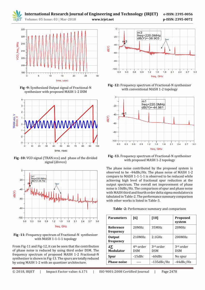
5. SIMULATION RESULTS AND DISCUSSIONS The envelope simulation is performed in Keysight ADS and a synthesized output signal with an output frequency of 200MHz is generated is shown in Fig-9.The output of the vco signal with a phase of the divider ratio for the synthesizer is shown in Fig-10.The frequency response of 4th order MASH ∆∑ Fractional-N synthesizer is shown in Fig-11. The spurs present on both left and right side band of the carrier. For the fractional-N synthesizer with 4th order DSM, the phase noise is observed to be -34dBc/Hz at 220MHz.
The macro-model with conventional MASH 1-2 ∆∑ modulator as subsystem is simulated and the frequency spectrum of the synthesizer is shown in Fig-12. The occurrence of fractional and reference spur is less compared to the model with 4th order DSM. The phase noise contributed by 3rd order conventional MASH 1-2 is observed to be -38dBc/Hz.
International Research Journal of Engineering and Technology (IRJET) e-ISSN: 2395-0056
Volume: 05 Issue: 03 | Mar-2018 www.irjet.net p-ISSN: 2395-0072
© 2018, IRJET | Impact Factor value: 6.171 | ISO 9001:2008 Certified Journal | Page 2478
Fig -9: Synthesized Output signal of Fractional-N synthesizer with proposed MASH 1-2 DSM
Fig -10: VCO signal (TRAN.vco) and phase of the divided signal (divvco)
Fig -11: Frequency spectrum of Fractional-N synthesizer with MASH 1-1-1-1 topology
From Fig-11 and Fig-12, it can be seen that the contribution of phase noise is reduced by using third order DSM. The frequency spectrum of proposed MASH 1-2 Fractional-N synthesizer is shown in Fig-13. The spurs are totally reduced by using MASH 1-2 with an quantizer architecture.
Fig -12: Frequency spectrum of Fractional-N synthesizer with conventional MASH 1-2 topology
Fig -13. Frequency spectrum of Fractional-N synthesizer with proposed MASH 1-2 topology
The phase noise contributed by the proposed system is observed to be -44dBc/Hz. The phase noise of MASH 1-2 compare to MASH 1-1-1-1 is observed to be reduced while achieving high level of fractional spur reduction at the output spectrum. The overall net improvement of phase noise is 10dBc/Hz. The comparison of spur and phase noise with MASH third and fourth order delta sigma modulators is tabulated in Table-2. The performance summary comparison with other works is listed in Table-3.
Table -2: Performance summary and comparison
Parameters [6] [10] Proposed system
Reference frequency
20MHz 35MHz 20MHz
Output frequency
210MHz 2.1GHz 200MHz
∆∑ Modulator
4th order DSM
3rd order DSM
3rd order DSM
Spur -15dBc -60dBc No spur
Phase noise ---- -135dBc/Hz -44dBc/Hz

International Research Journal of Engineering and Technology (IRJET) e-ISSN: 2395-0056
Volume: 05 Issue: 03 | Mar-2018 www.irjet.net p-ISSN: 2395-0072
© 2018, IRJET | Impact Factor value: 6.171 | ISO 9001:2008 Certified Journal | Page 2479
@1MHz Offset
@ 210MHz Offset
Settling time 3.32 µs 7µs 5 µs
Loop filter Second order
Passive third order
Passive second order
Table -3: Comparison with prior works
Parameters [6] [10] Proposed system
Reference frequency
20MHz 35MHz 20MHz
Output frequency
210MHz 2.1GHz 200MHz
∆∑ Modulator
4th order DSM
3rd order DSM
3rd order DSM
Spur -15dBc -60dBc No spur
Phase noise ---- -135dBc/Hz @1MHz Offset
-44dBc/Hz
@ 210MHz Offset
Settling time 3.32 µs 7µs 5 µs
Loop filter Second order
Passive third order
Passive second order
5. CONCLUSION
A MASH 1-1-1-1 and MASH 1-2 delta sigma modulator architectures for 200MHZ fractional-N frequency synthesizer were successfully implemented. The result shows that increasing the order of the Δ∑ modulator will lead to more spurious tones and phase noise, and the best order DSM is the 3rd order because it gives better noise shaping and suppresses reference and fractional spurs . The transfer function proves that the system is stable because the phase margin is greater than 45° and less than 90°and also has faster settling time. In this paper a considerable improvement was achieved in minimizing phase noise and spurious noise level using proposed MASH 1-2 Δ∑ modulator. The net improvement of noise reduction is 10dBc/Hz by using MASH 1-2 modulator and also it provideslow complexity.This work is being carried out to implement an circuit level modeling of Fractional-N synthesizer with MASH 1-2 third order delta sigma modulator in CMOS 180nm technology using cadence for future work.
REFERENCES
[1] Meninger, S.E.; Perrott, M.H., "A 1-MHZ bandwidth 3.6-GHz 0.18-μm CMOS fractional-N synthesizer utilizing a hybrid PFD/DAC structure for reduced broadband phase noise," Solid-State Circuits, IEEE Journal of , vol.41, no.4, pp.966,980, April 2006.
[2] T. A. Riley, M. A. Copeland, and T. A. Kwasniewski, “Delta–Sigma modulation in fractional-N frequency synthesis,” IEEE J. Solid-State Circuits, vol. 28, pp. 553–559, May 1993.
[3] Michael H. Perrott, Mitchell D. Trott , Charles G. Sodini,“A modeling approach for ∑∆ fractional-N frequency synthesizers allowing straightforward noise analysis” IEEE Journal of Solid-State Circuits, Vol. 37, No. 8, August 2002.
[4] Lau, C.Y.; Perrott, M.H., "Fractional-N frequency synthesizer design at the transfer function level using a direct closed loop realization algorithm," Design Automation Conference, 2003. Proceedings , vol., no., pp.526,531, 2-6 June 2003.
[5] Delvadiya Harikrushna I , Prof. Mukesh Tiwari , Prof. Jay Karan Singh, Dr. Anubhuti Khare.,” Design, implementation and characterization of XOR phase detector for DPLL in 45 nm cmos technology”, Advanced Computing: An International Journal ( ACIJ ), Vol.2, No.6, November 2011.
[6] Tamilselvan v, Maran Ponnambalam, Premanand V. Chandramani.,” Spur Reduction Technique for Fractional-N Frequency Synthesizer with MASH 1-1-1-1 Sigma Delta Modulator”, International Conference on Communication and Signal Processing, April 3-5, 2014.
[7] Tao Xu; Condon, M., "Comparative study of the MASH digital delta-sigma modulators," Research in Microelectronics and Electronics, 2009. PRIME 2009. Ph.D. , vol., no., pp.196,199, 12-17 July 2009.
[8] Lizhong Sun; Lepley, T.; Nozahic, F.; Bellissant, A.; Kwasniewski, T.; Heim, B., "Reduced complexity, high performance digital delta-sigma modulator for fractional-N frequency synthesis," Circuits and Systems, 1999. ISCAS '99. Proceedings of the 1999 IEEE International Symposium on , vol.2, no., pp.152,155 vol.2, Jul 1999.