Embed Size (px)
Citation preview

Martin® MMX, MIX, & MVX Electric Vibrators
Operator’s Manual M3882

ImportantMARTIN ENGINEERING HEREBY DISCLAIMS ANY LIABILITY FOR: DAMAGE DUE TO CONTAMINATION OF THE MATERIAL; USER’S FAILURE TO INSPECT, MAINTAIN AND TAKE REASONABLE CARE OF THE EQUIPMENT; INJURIES OR DAMAGE RESULTING FROM USE OR APPLICATION OF THIS PRODUCT CONTRARY TO INSTRUCTIONS AND SPECIFICATIONS CONTAINED HEREIN. MARTIN ENGINEERING’S LIABILITY SHALL BE LIMITED TO REPAIR OR REPLACEMENT OF EQUIPMENT SHOWN TO BE DEFECTIVE.Observe all safety rules given herein along with owner and Government standards and regulations. Know and understand lockout/tagout procedures as defined by American National Standards Institute (ANSI) z244.1-1982, American National Standard for Personnel Protection - Lockout/Tagout of Energy Sources - Minimum Safety Requirements and Occupational Safety and Health Administration (OSHA) Federal Register, Part IV, 29 CFR Part 1910, Control of Hazardous Energy Source (Lockout/Tagout); Final Rule.
The following symbols may be used in this manual:
DANGER!
Danger: Immediate hazards that will result in severe personal injury or death.
WARNING!
Warning: Hazards or unsafe practices that could result in personal injury.
CAUTION!
Caution: Hazards or unsafe practices that could result in product or property damages.
IMPORTANTImportant: Instructions that must be followed to ensure proper installation/operation of equipment.
NOTENote: General statements to assist the reader.

Martin Engineering M3882-01/15 i Martin® MMX, MIX, MVX Electric Vibrators
Table of Contents
Section PageList of Figures . . . . . . . . . . . . . . . . . . . . . . . . . . . . . . . . . . . . . . . . . . . . . . . . . . . . . . . . . . . . . . . . . . . iiList of Tables . . . . . . . . . . . . . . . . . . . . . . . . . . . . . . . . . . . . . . . . . . . . . . . . . . . . . . . . . . . . . . . . . . . . iiIntroduction . . . . . . . . . . . . . . . . . . . . . . . . . . . . . . . . . . . . . . . . . . . . . . . . . . . . . . . . . . . . . . . . . . . . . 1
General . . . . . . . . . . . . . . . . . . . . . . . . . . . . . . . . . . . . . . . . . . . . . . . . . . . . . . . . . . . . . . . . . . . . . . 1References . . . . . . . . . . . . . . . . . . . . . . . . . . . . . . . . . . . . . . . . . . . . . . . . . . . . . . . . . . . . . . . . . . . 1Safety . . . . . . . . . . . . . . . . . . . . . . . . . . . . . . . . . . . . . . . . . . . . . . . . . . . . . . . . . . . . . . . . . . . . . . . 1Storage . . . . . . . . . . . . . . . . . . . . . . . . . . . . . . . . . . . . . . . . . . . . . . . . . . . . . . . . . . . . . . . . . . . . . . 1
Before Installing Vibrator . . . . . . . . . . . . . . . . . . . . . . . . . . . . . . . . . . . . . . . . . . . . . . . . . . . . . . . . . . 2Installing Vibrator . . . . . . . . . . . . . . . . . . . . . . . . . . . . . . . . . . . . . . . . . . . . . . . . . . . . . . . . . . . . . . . . 3
Mounting vibrator onto screen frame. . . . . . . . . . . . . . . . . . . . . . . . . . . . . . . . . . . . . . . . . . . . . . . 3Nut and cap screw torque . . . . . . . . . . . . . . . . . . . . . . . . . . . . . . . . . . . . . . . . . . . . . . . . . . . . . . . . 4Markings on vibrators . . . . . . . . . . . . . . . . . . . . . . . . . . . . . . . . . . . . . . . . . . . . . . . . . . . . . . . . . . 5Connecting power to vibrator. . . . . . . . . . . . . . . . . . . . . . . . . . . . . . . . . . . . . . . . . . . . . . . . . . . . . 6Thermostats . . . . . . . . . . . . . . . . . . . . . . . . . . . . . . . . . . . . . . . . . . . . . . . . . . . . . . . . . . . . . . . . . . 8Installing overload, short-circuit, and ground-fault protection . . . . . . . . . . . . . . . . . . . . . . . . . . . 8
After Installing Vibrator . . . . . . . . . . . . . . . . . . . . . . . . . . . . . . . . . . . . . . . . . . . . . . . . . . . . . . . . . . . 10Checking shaft rotation . . . . . . . . . . . . . . . . . . . . . . . . . . . . . . . . . . . . . . . . . . . . . . . . . . . . . . . . . 10Adjusting eccentric weights . . . . . . . . . . . . . . . . . . . . . . . . . . . . . . . . . . . . . . . . . . . . . . . . . . . . . 12Initial start-up/checking line current . . . . . . . . . . . . . . . . . . . . . . . . . . . . . . . . . . . . . . . . . . . . . . . 14Variable frequency inverter . . . . . . . . . . . . . . . . . . . . . . . . . . . . . . . . . . . . . . . . . . . . . . . . . . . . . . 14
Maintenance. . . . . . . . . . . . . . . . . . . . . . . . . . . . . . . . . . . . . . . . . . . . . . . . . . . . . . . . . . . . . . . . . . . . . 15Lubricating vibrator . . . . . . . . . . . . . . . . . . . . . . . . . . . . . . . . . . . . . . . . . . . . . . . . . . . . . . . . . . . 15Repairing vibrator and replacing bearings . . . . . . . . . . . . . . . . . . . . . . . . . . . . . . . . . . . . . . . . . . 16Inspecting vibrator . . . . . . . . . . . . . . . . . . . . . . . . . . . . . . . . . . . . . . . . . . . . . . . . . . . . . . . . . . . . 16
Part Numbers . . . . . . . . . . . . . . . . . . . . . . . . . . . . . . . . . . . . . . . . . . . . . . . . . . . . . . . . . . . . . . . . . . . . 17
Tab
le o
f C
onte
nts

Martin Engineering M3882-01/15 ii Martin® MMX, MIX, MVX Electric Vibrators
List of Figures
Figure Title Page1 Mounting Bolt Tightening Sequence . . . . . . . . . . . . . . . . . . . . . . . . . . . . . . . . . . . . . . . . 3
2 Vibrator Nameplates . . . . . . . . . . . . . . . . . . . . . . . . . . . . . . . . . . . . . . . . . . . . . . . . . . . . . 53 Wiring Diagrams . . . . . . . . . . . . . . . . . . . . . . . . . . . . . . . . . . . . . . . . . . . . . . . . . . . . . . . . 64 Installing Wire Connector . . . . . . . . . . . . . . . . . . . . . . . . . . . . . . . . . . . . . . . . . . . . . . . . . 75 Manual Reset Connections . . . . . . . . . . . . . . . . . . . . . . . . . . . . . . . . . . . . . . . . . . . . . . . . 86 Top-Mounted Shaker . . . . . . . . . . . . . . . . . . . . . . . . . . . . . . . . . . . . . . . . . . . . . . . . . . . . . 107 Side-Mounted Shaker . . . . . . . . . . . . . . . . . . . . . . . . . . . . . . . . . . . . . . . . . . . . . . . . . . . . 118 Adjusting Eccentric Weights . . . . . . . . . . . . . . . . . . . . . . . . . . . . . . . . . . . . . . . . . . . . . . . 129 Adjustable Weights Set at 80% (fixed weight shaded) . . . . . . . . . . . . . . . . . . . . . . . . . . . 13
10 Setting Eccentric Weights to Mirror Images . . . . . . . . . . . . . . . . . . . . . . . . . . . . . . . . . . . 1311 Martin® Electric Vibrator, P/N MXX70X06. . . . . . . . . . . . . . . . . . . . . . . . . . . . . . . . . . . 1812 Martin® Electric Vibrator, P/N MXX75X06. . . . . . . . . . . . . . . . . . . . . . . . . . . . . . . . . . . 2113 Martin® Electric Vibrator, P/N MXX165X04. . . . . . . . . . . . . . . . . . . . . . . . . . . . . . . . . . 2414 Martin® Electric Vibrator, P/N MXX175X04. . . . . . . . . . . . . . . . . . . . . . . . . . . . . . . . . . 2715 Martin® Electric Vibrator, P/N MXX175X04-T4. . . . . . . . . . . . . . . . . . . . . . . . . . . . . . . 30
List of Tables
Table Title PageI Mounting Bolts and Torque Requirements . . . . . . . . . . . . . . . . . . . . . . . . . . . . . . . . . . . . 4
II Vibrator Nut and Cap Screw Torque Requirements . . . . . . . . . . . . . . . . . . . . . . . . . . . . . 4III Lubrication . . . . . . . . . . . . . . . . . . . . . . . . . . . . . . . . . . . . . . . . . . . . . . . . . . . . . . . . . . . . 15IV Martin® Electric Vibrator MXX70X06 Part Numbers . . . . . . . . . . . . . . . . . . . . . . . . . . . 20V Martin® Electric Vibrator MXX75X06 Part Numbers . . . . . . . . . . . . . . . . . . . . . . . . . . . 23
VI Martin® Electric Vibrator MXX165X04 Part Numbers . . . . . . . . . . . . . . . . . . . . . . . . . . 26VII Martin® Electric Vibrator MXX175X04 Part Numbers . . . . . . . . . . . . . . . . . . . . . . . . . . 29
VIII Martin® Electric Vibrator MXX175X04-T4 Part Numbers . . . . . . . . . . . . . . . . . . . . . . . 32
Lis
t of
Fig
ures
/Tab
les

Martin Engineering M3882-01/15 1 Martin® MMX, MIX, MVX Electric Vibrators
Introduction
General Martin® Explosion-Proof Electric Vibrators, Models MMX, MIX and MVX, are designed and manufactured to ensure the best performance and reliability in severe-duty applications. These vibrators have an ambient temperature rating including mounting surface temperature of -13 to 131°F (-25 to 55°C). If operating the vibrator in environments beyond these temperatures, call Martin Engineering, as the vibrator may require rating reduction, more frequent lubrication, or lubrication substitution. Contact Martin Engineering for explosion-proof joint detail.
Safety All safety rules defined in the above documents and all owner/employer safety rules must be strictly followed when working on the vibrator.
References The following documents are referenced in this manual:• The National Electrical Code (NEC), National Fire Protection Association,
1 Batterymarch Park, P.O. Box 9101, Quincy MA 02269-9101.• American National Standards Institute (ANSI) z244.1-1982, American
National Standard for Personnel Protection - Lockout/Tagout of Energy Sources - Minimum Safety Requirements, American National Standards Institute, Inc., 1430 Broadway, New York, NY 10018.
• Code of Federal Regulation (CFR) 29, Part 1910, Control of Hazardous Energy Source (Lockout/Tagout); Final Rule, Department of Labor, Occupational Safety and Health Administration (OSHA), 32nd Floor, Room 3244, 230 South Dearborn Street, Chicago, IL 60604.
• CFR 29, Part 1910.15, Occupational Noise Exposure, Department of Labor, OSHA, 32nd Floor, Room 3244, 230 South Dearborn Street, Chicago, IL 60604.
Storage Store vibrator in an ambient temperature not less than 41°F (5°C) with a relative humidity not more than 60%. If the vibrator has been stored for 2 or more years, remove bearings, wash them, and repack them with new grease (see “Lubricating Vibrator”).
Intr
oduc
tion
Martin Engineering M3882-01/15 2 Martin® MMX, MIX, MVX Electric Vibrators
Before Installing Vibrator
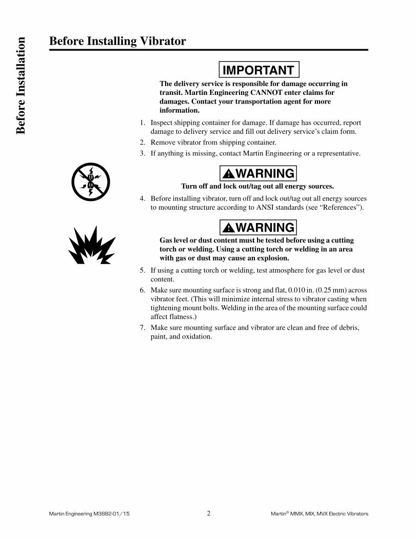
IMPORTANTThe delivery service is responsible for damage occurring in transit. Martin Engineering CANNOT enter claims for damages. Contact your transportation agent for more information.
1. Inspect shipping container for damage. If damage has occurred, report damage to delivery service and fill out delivery service’s claim form.
2. Remove vibrator from shipping container.
3. If anything is missing, contact Martin Engineering or a representative.
WARNING!
Turn off and lock out/tag out all energy sources.
4. Before installing vibrator, turn off and lock out/tag out all energy sources to mounting structure according to ANSI standards (see “References”).
WARNING!
Gas level or dust content must be tested before using a cutting torch or welding. Using a cutting torch or welding in an area with gas or dust may cause an explosion.
5. If using a cutting torch or welding, test atmosphere for gas level or dust content.
6. Make sure mounting surface is strong and flat, 0.010 in. (0.25 mm) across vibrator feet. (This will minimize internal stress to vibrator casting when tightening mount bolts. Welding in the area of the mounting surface could affect flatness.)
7. Make sure mounting surface and vibrator are clean and free of debris, paint, and oxidation.
Bef
ore
Inst
alla
tion

Martin Engineering M3882-01/15 3 Martin® MMX, MIX, MVX Electric Vibrators
Installing Vibrator
Mounting vibrator onto screen frame
IMPORTANTRead entire section before beginning work. See Appendix for overall dimensions and mounting dimensions.
CAUTION!
If installation instructions are not followed, structure and vibrator can be damaged. Abusing or dropping vibrator will accelerate wear and cause bearing damage.
Never weld structure with vibrator mounted and wired. Welding may cause damage to screen vibrator windings and bearings.
Use only new Grade 5 or 8 bolts, nuts, and compression washers. Old fasteners can break and cause damage to vibrator or structure.
Do not use split lock washers to install vibrator onto mount. Damage to vibrator could result.
Tighten mounting bolts in sequence shown in Figure 1. If not tightened in order, vibrator casting could be damaged.
1. Position vibrator mounting holes over mounting holes on screen frame. Use bolts to hold unit in place. Tighten bolts in order given in Figure 1 to avoid damaging vibrator casting.
2. Position vibrators so bolts are free in holes. (There should be no side load on bolts.) While holding unit in position, torque bolts per torque specifications in Table I or contact fastener manufacturer.
Figure 1. Mounting Bolt Tightening Sequence
1
3
4
2
3
1
5
6
2
4
4 Bolts 6 Bolts
Inst
alla
tion

Martin Engineering M3882-01/15 4 Martin® MMX, MIX, MVX Electric Vibrators
3. After the vibrator has been operated for 10 to 20 minutes, check bolttorque. Tighten if necessary.
Table I. Mounting Bolts and Torque Requirements*
*Torque specifications are for reference only. Contact fastener manufacturer for specific informationregarding bolt torque.
Nut and cap screw torque
After removing any nuts or cap screws from vibrator assembly, re-install to the torque values specified in Table II.
Table II. Vibrator Nut and Cap Screw Torque Requirements
Vibrator Type Frame Size*English Metric
Bolt Size(gr 5)
Dry Torque(ft-lb)
Bolt SizeDry Torque
(kgm)
MMX65 3/4 in. -10NC 288 M20 38
75 7/8 in. -9NC 430 M22 56
MIX65 5/8 in. -11NC 137 M16 19
75 1 in. -8NC 644 M25 89
MVX 65, 75 3/4 in. -10NC 288 M20 38
Cap Screws ft/lb (kgm)Terminal
Block Nutsft/lb (kgm)
M6 7 (1) M4 0.87 (0.12)
M8 16.5 (2.3) M5 1.45 (0.20)
M10 35 (4.8) M6 2.17 (0.30)
M12 58 (8) M8 4.70 (0.65)
M14 94 (13) M10 9.80 (1.35)
M16 137 (19)
M18 195 (27)
M20 275 (38)
Inst
alla
tion

Martin Engineering M3882-01/15 5 Martin® MMX, MIX, MVX Electric Vibrators
Inst
alla
tion

Martin Engineering M3882-01/15 6 Martin® MMX, MIX, MVX Electric Vibrators
Connecting power to vibrator
WARNING!
Wire vibrator in accordance with National Electrical Code (Articles 430, 500, 501 and 502, as appropriate) and all applicable local codes. Have wiring installed by a qualified electrician only.
Wire vibrators according to wiring diagrams in Figure 3.
Figure 3. Wiring Diagrams
CAUTION!
Before running cord to vibrator, make sure cord voltage rating equals or exceeds the voltage at which you will be operating the vibrator. It must have a minimum temperature rating of 222°F (105°C).
1. Remove wiring cover, O-ring, and rubber compression block. Install elbow or conduit fitting as appropriate. Install cord so that cord jacket extends into wiring compartment approximately 1 inch. Complete installation of wiring kit in accordance with their installation instructions.
IMPORTANTWhen wiring vibrator, leave slack in electrical cable so that cable does not become taut during vibration cycle and cause stress on wire connections. On applications where moisture is present, leave enough slack in power cable to prevent moisture from running down cable into vibrator.
2. Trim conductors and strip insulation approximately 1/4 inch. Wire vibrator according to wiring diagram inside terminal box or see Figure 3. Use closed-loop wire connectors only.
Cable EntryHigh Voltage Low Voltage
6-lead, 3-phase with Thermostat
Thermostat Circuit
Cable EntryHigh Voltage Low Voltage
6-lead, 3-phase
Inst
alla
tion

Martin Engineering M3882-01/15 7 Martin® MMX, MIX, MVX Electric Vibrators
Figure 4. Installing Wire Connector
3. Install wire connector between the two flat washers. See Figure 4.
WARNING!
Vibrator must be grounded using the power supply ground wire (or other if specified in the NEC). Failure to properly ground vibrator can cause severe injury or death.
4. Connect power supply ground wire (or other if specified in the NEC) to ground terminal. Use closed loop wire connector only.
WARNING!
All cable entry devices and blanking elements shall be certified in type of explosion protection flame-proof enclosure ‘d’ and ‘tD’, suitable for the conditions of use and correctly installed.Unusual apertures shall be closed with suitable blanking elements.
Wireconnector
Flatwashers
Inst
alla
tion

Martin Engineering M3882-01/15 8 Martin® MMX, MIX, MVX Electric Vibrators
ThermostatsWARNING!
Thermostats are intended for vibrator winding protection or to limit external vibrator surface temperatures. They do not replace overload protection.
NOTEThe thermostat terminals are identified as P1 and P2. The thermostat circuit is rated 600 Vac maximum and 720 VA. A manual momentary start switch must be used.
1. For MXX Vibrators, wire thermostats to control circuit. See Figure 5.
2. Reassemble wiring cover, o-ring, and rubber compression block, taking care not to pinch the o-ring.
Figure 5. Manual Reset Connections
Installing overload, short-circuit, and ground-fault protection
CAUTION!
Install overload protection for vibrator. If vibrator is not protected from overload, vibrator can be damaged and warranty will be void. Determine size of overload protection according to NEC Article 430, and have it installed by a qualified electrician only.
1. Determine overload, short-circuit, and ground-fault protection according to NEC Article 430.
2. Have qualified electrician install overload, short-circuit, and ground-fault protection.
3. If overload trips during operation, fix problem before resetting.
StopStart
1
2
3
Motor
Motor
Windings
P1
P2
StarterOverloadContacts
StarterCoil
W
V
U
Motor Starter
Line
Inst
alla
tion

Martin Engineering M3882-01/15 9 Martin® MMX, MIX, MVX Electric Vibrators
CAUTION!
For vibratory equipment using two vibrators (such as feeders, screens, and bin dischargers), the two vibrators must be electrically interlocked. If using a single contactor, each vibrator must be provided with separate overload protection. The vibrator control circuit must be arranged so that if one vibrator becomes de-energized, the other vibrator will automatically and immediately become de-energized. Failure to properly interlock vibrators could result in damage to equipment if one vibrator fails.
4. If using two vibrators, interlock the two vibrators and install separate overload protection for each.
Inst
alla
tion

Martin Engineering M3882-01/15 10 Martin® MMX, MIX, MVX Electric Vibrators
After Installing Vibrator
IMPORTANTRead entire section before beginning work.
Checking shaft rotation
1. Remove one weight cover.
WARNING!
Before checking shaft rotation, make sure area is known to be non-hazardous.
CAUTION!
DO NOT run vibrator with eccentric weights removed. Running vibrator with eccentric weights removed will damage bearings.
WARNING!
When checking shaft rotation with weight cover removed, keep hands away from swinging weights. Weights can crush fingers.
2. Start vibrator(s) only for a few seconds, then stop.
3. Observe direction of vibrator rotation. If vibrator is not rotating in correct direction, lock out/tag out energy source and reverse rotation. To reverse rotation of three-phase vibrator, reverse any two of the three power supply wires.
4. Replace weight cover, taking care not to pinch O-ring.
Figure 6. Top-Mounted Shaker
OR
Aft
er I
nsta
llati
on

Martin Engineering M3882-01/15 11 Martin® MMX, MIX, MVX Electric Vibrators
Figure 7. Side-Mounted Shaker
OR
Aft
er I
nsta
llati
on

Martin Engineering M3882-01/15 12 Martin® MMX, MIX, MVX Electric Vibrators
Adjusting eccentric weights
NOTEAll vibrators have one set of eccentric weights on each end of shaft. Eccentric weights are set at 80% at factory.The percentage increments on the weight adjustment disks are percentages of the total force pounds listed on the nameplate. For example, if the nameplate shows 8340 lb, setting the weights to 50% would produce 4170 pounds of force.
IMPORTANTFor the most efficient operation, vibrator eccentric weights should be adjusted to the lowest force setting required to move the material. This will increase vibrator life and reduce energy costs.
WARNING!
Before adjusting eccentric weights, turn off and lock out/tag out energy source to vibrator.
1. Turn off and lock out/tag out energy source to vibrator according to ANSI standards (see “References”).
2. Remove weight cover.
3. Loosen nut or screw (A, Figure 8) so adjustable weight (B) will rotate around shaft (C).
Figure 8. Adjusting Eccentric Weights
NOTEThe fixed weight is attached to the shaft. The adjustable weight rotates around the shaft.
4. See Figure 8. Rotate adjustable eccentric weight to proper setting. To produce more force, move weight to higher setting (i.e., higher number). When set, tighten cap screw or nut according to Table II.
AB
C
D
A.B.
Socket Head Cap ScrewAdjustable WeightShaftFixed Weight
C.D.
Aft
er I
nsta
llati
on

Martin Engineering M3882-01/15 13 Martin® MMX, MIX, MVX Electric Vibrators
Figure 9. Adjustable Weights Set at 80% (fixed weight shaded)
5. Check O-rings for damage. Replace if damaged.
CAUTION!
Do not operate vibrator with weight covers removed. Dust accumulating around vibrator shaft could cause unit to fail.
6. Replace weight covers.
CAUTION!
Adjust both sets of eccentric weights to same setting number (mirror images), or force output will be uneven and damage vibrator.
7. Repeat steps 2 through 5 for second set of weights. Set both sets of weights to same setting number so they are mirror images, as shown in Figure 10.
Figure 10. Setting Sets of Eccentric Weights to Mirror Images
Weight adjustment disk attached to fixed weight
Arrow showsdirection to turn
adjustable weightto increaseunbalance
INCORRECT CORRECT
Aft
er I
nsta
llati
on

Martin Engineering M3882-01/15 14 Martin® MMX, MIX, MVX Electric Vibrators
Initial start-up/checking line current
1. Close power supply disconnect switch and allow vibrator(s) to operate.
2. If vibrator makes unusual or excessive noise, make sure mounting bolts are tight and mount welds are not damaged.
WARNING!
Vibrator may produce loud noise during operation when mounted on structure. See OSHA 1910.95 for guidelines. If required, wear ear protection to avoid impairment or loss of hearing.
3. Check decibel level of vibrator noise during operation. See OSHA 1910.95 to determine whether noise exceeds safe limits. If required, wear ear protection to avoid impairment or loss of hearing.
CAUTION!
If vibrator is operated continuously with line current above nameplate rating, vibrator can be damaged.
4. After a few hours of operation, check each line current. If reading is higher than nameplate rating, check for correct phase voltage ensuring that it is correct and balanced. If phase voltages are correct (± 10% of nameplate rating) and balanced, recheck wiring, ensure that mounting bolts are correctly installed, or contact Martin Engineering for assistance. After making adjustments, check line current again to ensure line current does not exceed nameplate rating.
5. After first 8 hours of use and periodically thereafter, check mounting bolt torque and tighten if necessary.
Variable frequency inverter
CAUTION!
All vibrators can be supplied with a pulse-width modulated variable frequency inverter. NEVER operate the vibrator at a frequency higher than that specified on the nameplate. Damage to vibrator can result.
Do not operate vibrator at frequency higher than specified on nameplate. Throughout frequency range, verify that each line current does not exceed current rating on nameplate. If reading is higher than nameplate, consult inverter manual. If necessary, adjust inverter. After making adjustment, check line current again to ensure line current does not exceed nameplate rating.
Aft
er I
nsta
llati
on

Martin Engineering M3882-01/15 15 Martin® MMX, MIX, MVX Electric Vibrators
MaintenanceLubricating vibrator IMPORTANT
Read entire section before beginning work. Allow vibrator to cool to ambient temperature before working on it.
NOTEAll vibrators are lubricated at the factory.
CAUTION!
Use only prescribed grease in vibrator. If a different grease is used, vibrator can be damaged and warranty will be void.
Use only prescribed amount of grease to lubricate vibrator. Too much grease will cause bearings to overheat and result in premature bearing failure.
1. Lubricate the vibrator with Klüber ISOFLEX TOPAS NB 52 grease from Klüber Lubrication according to Table III.
Table III. Lubrication
CAUTION!
For 3600 rpm machines operating continuously or for long periods of time, reduce lubrication time and amount as described in step 2. Failure to do so could result in premature bearing failure.
2. If vibrator housing temperatures exceed 194°F (90°C), cut lubrication time and amount in half for every 18°F (10°C) increment that meets or exceeds 194°F (90°C).
NOTEKlüber grease may be purchased from Martin Engineering by calling 800-544-2947 or from Klüber Lubrication by calling 888-455-8237.
3. Lubricate with Klüber ISOFLEX TOPAS NB 52 grease only. Lubricate as follows:
a. Clean vibrator at each pipe plug in housing to remove dirt and debris. Remove pipe plug. Insert 1/8 in. NPT grease fitting. Add grease. Remove grease fittings; tightly replace pipe plugs. (Use anti-seize compound on threads.)
FrameSize
Quantitygrams per bearing
Frequencyhrs.
65 30 2000
75 40 2000
Mai
nten
ance

Martin Engineering M3882-01/15 16 Martin® MMX, MIX, MVX Electric Vibrators
Repairing vibrator and replacing bearings
CAUTION!
Repairing vibrator yourself during the warranty period may void the warranty. Contact Martin Engineering if motor needs repair.
If vibrator needs repair or if bearings need to be replaced, call your local representative or Martin Engineering at 800-544-2947 for instructions.
Inspecting vibrator
At least quarterly, inspect cable and connections as follows:
WARNING!
Before inspecting vibrator, turn off and lock out/tag out energy source to vibrator.
1. Turn off and lock out/tag out energy source to vibrator according to ANSI standards (see “References”).
2. Inspect cable for damage including cuts and abrasions. Replace if damaged.
3. Inspect ground connection. Make sure resistance from ground connection to vibrator enclosure does not exceed 0.1 ohm. Ensure screw on ground terminal is tightened to proper torque (see Table II).
4. Make sure all nuts on connections on terminal block are tightened to proper torque. Do not overtighten (see Table II).
5. Check mounting bolt torque (see Table I).
Mai
nten
ance

Martin Engineering M3882-01/15 17 Martin® MMX, MIX, MVX Electric Vibrators
Part Numbers
This section provides part numbers for the MMX Series Electric Vibrators. Please reference part numbers when ordering parts.
Par
t N
umbe
rs

Martin Engineering M3882-01/15 18 Martin® MMX, MIX, MVX Electric Vibrators
Figure 11. Martin® Electric Vibrator, P/N MXX70X06
WEIGHT COVER & TERMINAL BOX COVER REMOVED
SECTION A–A
WEIGHT COVERS, WEIGHTS,AND ADJUSTMENT DISK REMOVED
Par
t N
umbe
rs

Martin Engineering M3882-01/15 19 Martin® MMX, MIX, MVX Electric Vibrators
Item Description Part No. Qty
1 Case Casting Table IV 1
2 Stator Table IV 1
3 Shaft Assembly 803005 1
4 Flange Bearing 802004 2
5 Bearing Cylindrical Roller NJ2313ECP 506551 2
6 Bearing Cover 804004 2
7 Terminal Box Cover 806001 1
8 Weight Cover 805005-AL 2
9 Retaining Ring Internal 6.25 816002 2
10 Key 14 x 9 x 25 mm 809001 2
11 O-ring #377 10.00 ID x .210 CS 818003 2
12 V-ring Shaft Seal 55mm 502043 2
13 Terminal Block 812001 1
14 Snap Ring External A45 500063 2
15 Sticker Ground Symbol 821001 2
16 Cable Protection Sheath 814001 1
17 O-ring #259 6.25 ID x .139 CS 818002 1
18 Rubber Block 813001 1
19 Rubber Block Small 813002 1
20 Nameplate 820001 1
21 Nameplate Caution Disconnect 518147 1
22 Plug 1/2 NPT Internal Hex 39268 1
23 Nylon Cord Grip 3/4 NPT Range .51/.71 823001 1
24 Nameplate SS Warning Conduit Seal 820008 1
25 Weight Eccentric Fixed 807004-50F 4
26 Weight Adjustment Disk 808001-B 1
27 Weight Adjustment Disk 808001-A 1
28 Fitting Grease 1/8 NPT ZP 11814 2
29 Plug Hex Socket 3/4 NPT SS Dryseal 514520 1
30 Plug M10 x 10 mm Socket Head 509008 4
31 Washer Schnorr D12 VS Series ZPY 513006 12
32 Screw SHC M12 x 1.75 x 30 CL 12.9 BO 822002 8
33 Washer Schnorr D8 VS Series ZPY 513004 8
34 Screw SHC M8 x 1.25 x 20 CL 12.9 BO 515507 8
35 Washer Schnorr D10 VS Series ZPY 513005 4
36 Screw SHC M10 x 1.5 x 25 CL 12.9 ZP 515513 4
Par
t N
umbe
rs
Martin Engineering M3882-01/15 20 Martin® MMX, MIX, MVX Electric Vibrators
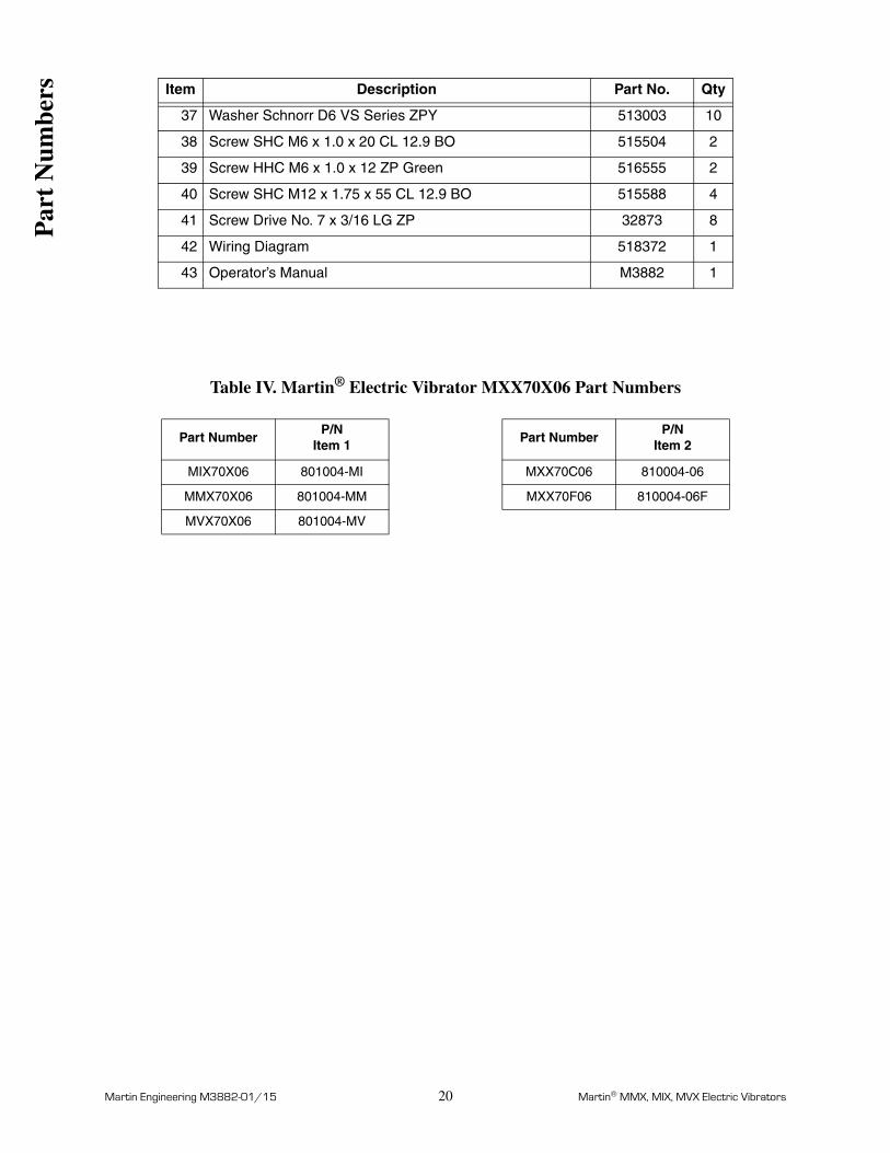
Table IV. Martin® Electric Vibrator MXX70X06 Part Numbers
37 Washer Schnorr D6 VS Series ZPY 513003 10
38 Screw SHC M6 x 1.0 x 20 CL 12.9 BO 515504 2
39 Screw HHC M6 x 1.0 x 12 ZP Green 516555 2
40 Screw SHC M12 x 1.75 x 55 CL 12.9 BO 515588 4
41 Screw Drive No. 7 x 3/16 LG ZP 32873 8
42 Wiring Diagram 518372 1
43 Operator’s Manual M3882 1
Part NumberP/N
Item 1Part Number
P/NItem 2
MIX70X06 801004-MI MXX70C06 810004-06
MMX70X06 801004-MM MXX70F06 810004-06F
MVX70X06 801004-MV
Item Description Part No. Qty
Par
t N
umbe
rs

Martin Engineering M3882-01/15 21 Martin® MMX, MIX, MVX Electric Vibrators
Figure 12. Martin® Electric Vibrator, P/N MXX75X06
WEIGHT COVER & TERMINAL BOX COVER REMOVED
SECTION A–A
WEIGHT COVERS, WEIGHTS,AND ADJUSTMENT DISK REMOVED
Par
t N
umbe
rs

Martin Engineering M3882-01/15 22 Martin® MMX, MIX, MVX Electric Vibrators
Item Description Part No. Qty
1 Case Casting Table V 1
2 Stator Table V 1
3 Shaft Assembly 803005 1
4 Flange Bearing 802004 2
5 Bearing Cylindrical Roller NJ2313ECP 506551 2
6 Bearing Cover 804004 2
7 Terminal Box Cover 806001 1
8 Weight Cover SP12675-WC 2
9 Retaining Ring Internal 6.25 816002 2
10 Key 14 x 9 x 25 mm 809001 2
11 O-ring #377 10.00 ID x .210 CS 818003 2
12 V-ring Shaft Seal 55mm 502043 2
13 Terminal Block 812001 1
14 Snap Ring External A45 500063 2
15 Sticker Ground Symbol 821001 2
16 Cable Protection Sheath 814001 1
17 O-ring #259 6.25 ID x .139 CS 818002 1
18 Rubber Block 813001 1
19 Rubber Block Small 813002 1
20 Plug 1/2 NPT Internal Hex 39268 1
21 Nameplate 820001 1
22 Nameplate ETL Class I 820002 1
23 Nameplate SS Warning Conduit Seal 820008 1
24 Nameplate Caution Disconnect 518147 1
25 Weight Eccentric Fixed 807004-50F 2
26 Weight Adjustment Disk 808004-06B 1
27 Weight Adjustment Weldment SP12675-AW 2
28 Weight Adjustment Disk 808004-06A 1
29 Plug 1/8-27NPTF Dryseal 509059 2
30 Plug Hex Socket 3/4 NPT SS Dryseal 514520 1
31 Plug M10 x 10 mm Socket Head 509008 4
32 Washer Schnorr D12 VS Series ZPY 513006 12
33 Screw SHC M12 x 1.75 x 30 CL 12.9 BO 822002 8
34 Washer Schnorr D8 VS Series ZPY 513004 8
35 Screw SHC M8 x 1.25 x 20 CL 12.9 BO 515507 8
36 Washer Schnorr D10 VS Series ZPY 513005 4
Par
t N
umbe
rs

Martin Engineering M3882-01/15 23 Martin® MMX, MIX, MVX Electric Vibrators
Table V. Martin® Electric Vibrator MXX75X06 Part Numbers
37 Screw SHC M10 x 1.5 x 25 CL 12.9 ZP 515513 4
38 Washer Schnorr D6 VS Series ZPY 513003 10
39 Screw SHC M6 x 1.0 x 20 CL 12.9 BO 515504 2
40 Screw HHC M6 x 1.0 x 12 ZP Green 516555 2
41 Screw SHC M12 x 1.75 x 55 CL 12.9 BO 515588 4
42 Screw Drive No. 7 x 3/16 LG ZP 32873 10
43 Wiring Diagram 518372 1
44 Operator’s Manual M3882 1
Part NumberP/N
Item 1Part Number
P/NItem 2
MIX75X06 801004-MI MXX75C06 810004-06
MMX75X06 801004-MM MXX75F06 810004-06F
MVX75X06 801004-MV
Item Description Part No. Qty
Par
t N
umbe
rs

Martin Engineering M3882-01/15 24 Martin® MMX, MIX, MVX Electric Vibrators
Figure 13. Martin® Electric Vibrator, P/N MXX165X04
WEIGHT COVERS, WEIGHTS,AND ADJUSTMENT DISK REMOVEDWEIGHT COVER & TERMINAL BOX COVER REMOVED
SECTION A–A
Par
t N
umbe
rs

Martin Engineering M3882-01/15 25 Martin® MMX, MIX, MVX Electric Vibrators
Item Description Part No. Qty
1 Case Casting Table VI 1
2 Stator Table VI 1
3 Shaft Assembly with Rotor and Bushing 803001 1
4 Flange Bearing 802001 2
5 Bearing Cylindrical Roller NJ2311ECP 506536 2
6 Bearing Cover 804001 2
7 Retaining Ring Internal 5.50 Flange 816001 2
8 Terminal Box Cover 806001 1
9 Key 14 x 9 x 25 mm 809001 2
10 Weight Eccentric Fixed Table VI 4
11 Weight Adjustment Disk 808001-A 1
12 Weight Adjustment Disk 808001-B 1
13 O-ring #373 9.00 I.D. x .210 CS 818001 2
14 Weight Cover 805001-AL 2
15 Plug M10 x 10mm Socket Head 509008 4
16 V-ring shaft seal 55mm 502043 2
17 Terminal Block 812001 1
18 Snap Ring External A45 500063 2
19 Sticker Ground Symbol 821001 2
20 Cable Protection Sheath 814001 1
21 O-ring #259 6.25 I.D. x .139 CS 818002 1
22 Neoprene Foam Block 813001 1
23 Neoprene Foam Block Small 813002 1
24 Plug 1/8-27NPTF Dryseal 509059 2
25 Plug Hex Socket 3/4-NPT SS Dryseal 514520 1
26 Nameplate 820001 1
27 Nameplate Caution Disconnect 518147 1
28 Nameplate SS Warning Conduit Seal 518334 1
29 Nameplate ETL Class 1 820002 1
30 Washer Schnorr D10 VS Series ZPY 513005 12
31 Screw SHC M10 x 1.50 x 30 CL 12.9 DC 515538 8
32 Washer Schnorr D12 VS Series ZPY 513006 4
33 Screw SHC M12 x 1.75 x 55 CL 12.9 BO 515588 4
34 Screw SHC M10 x 1.5 x 25 CL 12.9 ZP 515513 4
35 Washer Schnorr D6 VS Series ZPY 513003 10
36 Screw SHC M6 x 1.0 x 20 CL 12.9 BO 515504 2
Par
t N
umbe
rs

Martin Engineering M3882-01/15 26 Martin® MMX, MIX, MVX Electric Vibrators
Table VI. Martin® Electric Vibrator MXX165X04 Part Numbers
37 Screw HHC M6 x 1.0 x 12 ZP Green 516555 2
38 Washer Schnorr D8 VS Series ZPY 513004 8
39 Screw SHC M8 x 1.25 x 20 CL 12.9 ZP 515507 8
40 Screw Drive No. 7 x 3/16 LG ZP 32873 10
41 Wiring Diagram 518372 1
42 Operator’s Manual M3882 1
Part NumberP/N
Item 1Part Number
P/NItem 2
P/NItem 10
MILX165A04 801001-MIL MMX165A04 810002-04 807001-50F
MIX165C04 801001-MI MMX165C04 810002-04 807001-60F
MMX165F04 801001-MM MMX165F04 810002-04F 807001-60F
MVX165X04 801001-MV
Item Description Part No. Qty
Par
t N
umbe
rs

Martin Engineering M3882-01/15 27 Martin® MMX, MIX, MVX Electric Vibrators
Figure 14. Martin® Electric Vibrator, P/N MXX175X04
WEIGHT COVER & TERMINAL BOX COVER REMOVED
SECTION A–A
WEIGHT COVERS, WEIGHTS,AND ADJUSTMENT DISK REMOVED
Par
t N
umbe
rs

Martin Engineering M3882-01/15 28 Martin® MMX, MIX, MVX Electric Vibrators
Item Description Part No. Qty
1 Case Casting Table VII 1
2 Stator 4 Pole Table VII 1
3 Shaft Assembly 803005 1
4 Flange Bearing 802004 2
5 Bearing Cylindrical Roller NJ2313ECP 506551 2
6 Bearing Cover 804004 2
7 Terminal Box Cover 806001 1
8 Weight Cover Aluminum 805005-AL 2
9 Retaining Ring Internal 6.25 816002 2
10 Key 14 x 9 x 25 mm 809001 2
11 O-ring #377 10.00 I.D. x .210 CS 818003 2
12 V-ring shaft seal 55mm 502043 2
13 Terminal Block 812001 1
14 Snap Ring External A45 500063 2
15 Sticker Ground Symbol 821001 2
16 Cable Protection Sheath 814001 1
17 O-ring #259 6.25 I.D. x .139 CS 818002 1
18 Neoprene Foam Block 813001 1
19 Neoprene Foam Block Small 813002 1
20 Nameplate 820001 1
21 Nameplate Caution Disconnect 518147 1
22 Plug 1/2 NPT Internal Hex Plain Finish 39268 1
23 Nameplate ETL Class 1 820002 1
24 Nameplate SS Warning Conduit Seal 820008 1
25 Weight Eccentric Fixed Table VII 4
26 Weight Adjustment Disk 808001-B 1
27 Weight Adjustment Disk 808001-A 1
28 Plug 1/8-27NPTF Dryseal 509059 2
29 Plug Hex Socket 3/4-NPT SS Dryseal 514520 1
30 Plug M10 x 10mm Socket Head 509008 4
31 Washer Schnorr D12 VS Series ZPY 513006 12
32 Screw SHC M12 x 1.75 x 30 CL 12.9 BO 822002 8
33 Washer Schnorr D8 VS Series ZPY 513004 8
34 Screw SHC M8 x 1.25 x 20 CL 12.9 ZP 515507 8
35 Washer Schnorr D10 VS Series ZPY 513005 4
36 Screw SHC M10 x 1.5 x 25 CL 12.9 ZP 515513 4
Par
t N
umbe
rs

Martin Engineering M3882-01/15 29 Martin® MMX, MIX, MVX Electric Vibrators
Table VII. Martin® Electric Vibrator MXX175X04 Part Numbers
37 Washer Schnorr D6 VS Series ZPY 513003 10
38 Screw SHC M6 x 1.0 x 20 CL 12.9 BO 515504 2
39 Screw HHC M6 x 1.0 x 12 ZP Green 516555 2
40 Screw SHC M12 x 1.75 x 55 CL 12.9 BO 515588 4
41 Screw Drive No. 7 x 3/16 LG ZP 32873 10
42 Wiring Diagram 518372 1
43 Operator’s Manual M3882 1
Part NumberP/N
Item 1Part Number
P/NItem 2
P/NItem 25
MIX175X04 801004-MI MVX175A04 810004-04 807004-50F
MMX175X04 801004-MM MVX175C04 810004-04 807004-60F
MVX175X04 801004-MV MVX175F04 810004-04F 807004-60F
MVX175Q04 810004-04Q 807004-50F
Item Description Part No. Qty
Par
t N
umbe
rs

Martin Engineering M3882-01/15 30 Martin® MMX, MIX, MVX Electric Vibrators
Figure 15. Martin® Electric Vibrator, P/N MXX175X04-T4
WEIGHT COVER & TERMINAL BOX COVER REMOVED
SECTION A–A
WEIGHT COVERS, WEIGHTS,AND ADJUSTMENT DISK REMOVED
Par
t N
umbe
rs

Martin Engineering M3882-01/15 31 Martin® MMX, MIX, MVX Electric Vibrators
Item Description Part No. Qty
1 Case Casting 801004-MX 1
2 Stator with Thermostat 4 Pole Table VIII 1
3 Shaft Assembly 803005 1
4 Flange Bearing 802004 2
5 Bearing Cylindrical Roller NJ2313ECP 506551 2
6 Bearing Cover 804004 2
7 Terminal Box Cover 806001 1
8 Weight Cover Aluminum 805005-AL 2
9 Retaining Ring Internal 6.25 816002 2
10 Key 14 x 9 x 25 mm 809001 2
11 O-ring #377 10.00 I.D. x .210 CS 818003 2
12 V-ring shaft seal 55mm 502043 2
13 Terminal Block 812001 1
14 Snap Ring External A45 500063 2
15 Sticker Ground Symbol 821001 2
16 Cable Protection Sheath 814001 1
17 O-ring #259 6.25 I.D. x .139 CS 818002 1
18 Neoprene Foam Block 813001 1
19 Neoprene Foam Block Small 813002 1
20 Nameplate 820001 1
21 Nameplate Caution Disconnect 518147 1
22 Plug 1/2 NPT Internal Hex Plain Finish 39268 1
23 Nameplate ETL for MXX Class 1 T4 Vibrator 820009 1
24 Nameplate SS Warning Conduit Seal 820008 1
25 Adapter Thread Locking Slotted Insert 509056 1
26 Terminal Block 2 Position 510510 1
27 Screw Slotted PHMS M3.5 x 0.6 x 15 CL 4.8 ZP 515609 1
28 Weight Eccentric Fixed Table VIII 4
29 Weight Adjustment Disk 808001-B 1
30 Weight Adjustment Disk 808001-A 1
31 Plug 1/8-27NPTF Dryseal 509059 2
32 Plug Hex Socket 3/4-NPT SS Dryseal 514520 1
33 Plug M10 x 10mm Socket Head 509008 4
34 Washer Schnorr D12 VS Series ZPY 513006 12
35 Screw SHC M12 x 1.75 x 30 CL 12.9 BO 822002 8
36 Washer Schnorr D8 VS Series ZPY 513004 8
Par
t N
umbe
rs

Martin Engineering M3882-01/15 32 Martin® MMX, MIX, MVX Electric Vibrators
Table VIII. Martin® Electric Vibrator MXX175X04-T4 Part Numbers
37 Screw SHC M8 x 1.25 x 20 CL 12.9 ZP 515507 8
38 Washer Schnorr D10 VS Series ZPY 513005 4
39 Screw SHC M10 x 1.5 x 25 CL 12.9 ZP 515513 4
40 Washer Schnorr D6 VS Series ZPY 513003 10
41 Screw SHC M6 x 1.0 x 20 CL 12.9 BO 515504 2
42 Screw HHC M6 x 1.0 x 12 ZP Green 516555 2
43 Screw SHC M12 x 1.75 x 55 CL 12.9 BO 515588 4
44 Screw Drive No. 7 x 3/16 LG ZP 32873 10
45 Wiring Diagram 518372 1
46 Operator’s Manual M3882 1
Part NumberP/N
Item 2P/N
Item 28
MXX175A04-T4 801004--04-T 807004-50F
MXX175C04-T4 801004-04-T 807004-60F
MXX175F04-T4 801004-04F-T 807004-60F
MXX175Q04-T4 801004-04Q-T 807004-50F
Item Description Part No. Qty
Par
t N
umbe
rs

Martin Engineering M3882-01/15 A-1 Martin® MMX, MIX, MVX Electric Vibrators
AppendixMartin® Electric Vibrator Dimensions
App
endi
x

Martin Engineering M3882-01/15 A-2 Martin® MMX, MIX, MVX Electric Vibrators
Mar
tin
Ele
ctri
c V
ibra
tor
Dim
ensi
ons
(in.
[m
m])
P/N
AB
CD
EF
Fo
ot
Ho
les
HØ
GN
o.
MM
X70
X06
24.7
2 (6
28)
13.5
0 (3
43)
12.4
0 (3
15)
6.10
(15
5)10
.04
(255
)1.
14 (
29)
.93
(23.
50)
46.
10 (
155)
MIX
70X
0624
.72
(628
)13
.50
(343
)12
.40
(315
)3.
35 (
85)
10.6
3 (2
70)
1.14
(29
)1.
02 (
26)
66.
10 (
155)
MV
X70
X06
24.7
2 (6
28)
13.5
0 (3
43)
12.4
0 (3
15)
4.13
(10
5)9.
76 (
248)
1.14
(29
).8
7 (2
2)6
6.10
(15
5)
MM
X75
X06
26.1
4 (6
64)
13.5
0 (3
43)
12.4
0 (3
15)
6.10
(15
5)10
.04
(255
)1.
14 (
29)
.93
(23.
50)
46.
10 (
155)
MIX
75X
0626
.14
(664
)13
.50
(343
)12
.40
(315
)3.
35 (
85)
10.6
3 (2
70)
1.14
(29
)1.
02 (
26)
66.
10 (
155)
MV
X75
X06
26.1
4 (6
64)
13.5
0 (3
43)
12.4
0 (3
15)
4.13
(10
5)9.
76 (
248)
1.14
(29
).8
7 (2
2)6
6.10
(15
5)
MM
X16
5X04
23.3
1 (5
92)
12.2
0 (3
10)
10.6
3 (2
70)
6.10
(15
5)8.
86 (
225)
1.17
(29
.6)
.87
(22)
45.
31 (
135)
MIX
165X
0423
.31
(592
)12
.20
(310
)10
.63
(270
)3.
15 (
80)
8.27
(21
0)1.
17 (
29.6
).6
7 (1
7)6
5.31
(13
5)
MIL
X16
5X04
23.3
1 (5
92)
12.2
0 (3
10)
10.6
3 (2
70)
3.15
(80
)8.
27 (
210)
1.17
(29
.6)
.78
(19.
80)
65.
31 (
135)
MV
X16
5X04
23.3
1 (5
92)
12.2
0 (3
10)
10.6
3 (2
70)
3.27
(83
)9.
02 (
229)
1.17
(29
.6)
.87
(22)
65.
31 (
135)
MM
X17
5X04
24.7
2 (6
28)
13.5
0 (3
43)
12.4
0 (3
15)
6.10
(15
5)10
.04
(255
)1.
14 (
29)
.93
(23.
50)
46.
10 (
155)
MIX
175X
0424
.72
(628
)13
.50
(343
)12
.40
(315
)3.
35 (
85)
10.6
3 (2
70)
1.14
(29
)1.
02 (
26)
66.
10 (
155)
MV
X17
5X04
24.7
2 (6
28)
13.5
0 (3
43)
12.4
0 (3
15)
4.13
(10
5)9.
76 (
248)
1.14
(29
).8
7 (2
2)6
6.10
(15
5)
MM
X17
5X04
24.7
2 (6
28)
13.5
0 (3
43)
12.4
0 (3
15)
6.10
(15
5)10
.04
(255
)1.
14 (
29)
.93
(23.
50)
46.
10 (
155)
MIX
175X
0424
.72
(628
)13
.50
(343
)12
.40
(315
)3.
35 (
85)
10.6
3 (2
70)
1.14
(29
)1.
02 (
26)
66.
10 (
155)
MV
X17
5X04
24.7
2 (6
28)
13.5
0 (3
43)
12.4
0 (3
15)
4.13
(10
5)9.
76 (
248)
1.14
(29
).8
7 (2
2)6
6.10
(15
5)
DG
A
F
E C
B
H
DG
A
D
App
endi
x

Any product, process, or technology described here may be the subject of intellectual property rights reserved by Martin Engineering Company. Trademarks or service marks designated with the ® symbol are registered with the U.S. Patent and Trademark Office and may be proprietary in one or more countries or regions. Other trademarks and service marks belonging to Martin Engineering Company in the United States and/or other countries or regions may be designated with the “TM” and “SM” symbols. Brands, trademarks, and names of other parties, who may or may not be affiliated with, connected to, or endorsed by Martin Engineering Company, are identified wherever possible. Additional information regarding Martin Engineering Company’s intellectual property can be obtained at www.martin-eng.com/trademarks.

Martin Engineering USAOne Martin PlaceNeponset, IL 61345-9766 USA800 544 2947 or 309 852 2384Fax 800 814 1553www.martin-eng.com
Form No. M3882-01/15 © Martin Engineering Company 2011, 2015