Embed Size (px)
Citation preview
March 2016 UF Electronic Access Control Standards Page 1 of 54
SECTION 281300 – ACCESS CONTROL
PART 1 GENERAL
1. SCOPE OF WORK
1. SCOPE OF WORK FOR DESIGNER AND CONSULTANTS
I. See paragraph 1.1 in specification section 280500
2. SCOPE OF WORK FOR CONTRACTORS
II. See paragraph 1.1 in specification section 280500
2. RELATED DOCUMENTS
I. Drawings and general provisions of the Contract, including General andSupplementary Conditions and Division1 Specification Sections, apply tothis Section.
II. The following documents from Division 28 - Electronic Safety andSecurity of the UF Access Control, Surveillance and SecuritySpecifications are also relevant to this Section:
1. Section 280500 Common Work Results for Electronic Safety and Security(http://www.ppd.ufl.edu/PPDITS/pdf/280500-CommonWorkResults.pdf)
2. Section 281600 Intrusion Detection(http://www.ppd.ufl.edu/PPDITS/pdf/281600-IntrusionDetection.pdf)
3. Section 282300 Video Surveillance(http://www.ppd.ufl.edu/PPDITS/pdf/282300-VideoSurveillance.pdf)
III. The following documents also apply to this Section:
1. Section 08700 “Door Hardware” of the UF Design and Construction Standard.
2. UF Key and Lock Policy (http://www.ppd.ufl.edu/pdf/Key_Lock_Policy.pdf)
3. UF Telecommunications Standards (http://net-services.ufl.edu/infrastructure/)
4. UF IT Policies and Standards (http://www.it.ufl.edu/policies/)
5. UF IT Security Regulations (http://www.it.ufl.edu/policies/security/)

March 2016 UF Electronic Access Control Standards Page 2 of 54
IV. Design and operation of the system shall conform to the following referenced codes, regulations, and standards as applicable:
1. National Electrical Code (NEC), edition indicated in the current Florida Building Code.
2. Life Safety Code (NFPA 101), edition indicated in the current Florida Building Code.
3. Florida Building Code, current edition.
4. Electronic Industry Association ANSI/EIA/TIA
5. National Electrical Manufacturers Association (NEMA)
6. Underwriters Laboratories UL 294, UL 639, and UL 1037, UL 1076
7. National Fire Protection Association (NFPA)
8. Federal Communications Commission (FCC) 47 CRF Part 15 and 90
9. Applicable Federal, State, and Local Laws, Regulations, and Codes
3. CONTRACTOR QUALIFICATIONS
A. A list of Lenel vendors/installers approved by UF PPD ITS can be found on the PPD website (http://www.ppd.ufl.edu/PPDITS/pdf/uflenelvendors.pdf).
B. If under previous written approval by UF PPD ITS it is acceptable to use a different contractor than one of the contractors previously mentioned, the new contractor, as a minimum, shall have the following qualifications:
1. The contractor must be a direct Lenel Authorized Value Added Reseller (VAR) and a certified Lenel OnGuard Pro dealer.
2. The contractor shall submit a letter issued by Lenel authorizing this contractor to provide and install Lenel equipment for UF.
3. The contractor shall have a fully staffed office and service department located within 125 miles of Gainesville, Florida.
4. The contractor shall agree, in writing, as part of their proposal, to provide both warranty and non-warranty service within 4 hours of notification of a problem. The contractor shall be able to perform any and all repairs to the systems they install within 24 hours.
5. All technicians assigned to install and configure systems in UF facilities shall be Lenel-trained and certified for the proper installation of this equipment and be thoroughly familiar with all aspects of the software and control hardware. The contractor must have a minimum of 3 qualified and factory-trained technicians on staff to support this system.
6. The Contractor shall have at least two Lenel access control trained and certified technician’s onsite when system installation work is being performed.

March 2016 UF Electronic Access Control Standards Page 3 of 54
7. The Contractor technicians shall be trained and experienced to work with Sargent and Von Duprin electrified locking hardware, must be able to understand and configure complex input, output, and timer logic and have experience troubleshooting impedance issues as well as door hardware installation issues.
8. The Contractor shall be an experienced firm regularly engaged in the layout and installation of systems of similar size and complexity as required for this installation.
9. The Contractor shall have successfully completed the layout, installation, programing, testing and warranty of not less than five systems of similar scope of this project for a minimum period of three years prior to the bid date, and shall have been regularly engaged in the business of access control and security contracting.
10. The contractor shall submit a list of all employees that will be doing work on campus. This list will need to be submitted quarterly and must be resubmitted immediately when there are any personnel changes that impact the list.
11. The contractor, as a minimum, must carry a current state-issued limited energy (low voltage) license.
12. Along with a project security bid a security contractor shall be required to provide example as-built and wiring diagram documents used on systems of similar size and scope. (100+ reader installations). The contractor will need to provide photos of previous installations depicting wiring methods and installation workmanship.
i. Example as-built floorplan layouts with reader, control board and camera layouts
ii. Example wiring diagrams developed by the firm depicting the integration of an access system with another building control system. i.e. ADA, Intrusion system, intercom, man-trap. Etc.
iii. 10 photos of installation enclosures depicting use of wire management and wire labeling.
iv. 3 References customers of similar size and scope (100+ reader installation) with contact information and willing to correspond with PPD-ITS
March 2016 UF Electronic Access Control Standards Page 4 of 54
4. SUBSTITUTIONS AND ALTERNATE METHODS
A. Because of compatibility issues, the hardware and software manufactured by Lenel and specified herein may not be substituted. Equipment and software shall be provided as specified.
1. Sensors or door security devices allow substitutions as long as they can be proven equivalent to the basis of design given in this specification. In order for the new product to be accepted as an equivalent, the security contractor shall follow these steps:
2. Submit a variance request form, attaching a complete list of such substituted products with drawings and product data sheets. The Electronic Access Variance Request form can be found on the PPD website (http://www.ppd.ufl.edu/PPDITS/pdf/div28varianceform.pdf).
B. Receive an approved variance request form, signed by UF PPD ITS. The contractor is not authorized to install any substitute equipment before receiving an approved variance request form.
C. Substitute equipment must be a standard part of that system's current product line and should meet or exceed the capabilities of the equipment specified herein. Beta, Specials, or “One Time” products will not be acceptable. If proposed substitutions do not meet or exceed the performance levels specified herein, the limitations of this equipment must be highlighted and brought to the attention of the designer and/or consultant. Failure to notify the designer/consultant of these limitations, whether intentionally or by oversight may result in rejection of those components at any time. Should this occur, the contractor will be required to replace the rejected equipment with pre-approved components that meet or exceed the requirements as specified herein. This will be done at no additional cost to the client.
D. Alternate methods: When the contractor proposes alternate methods to a UF standard practice indicated in this specification, the contractor shall follow the same process as for equipment substitutions. The contractor shall submit a variance request form and obtain approval from UF PPD ITS before applying any alternate methods.
5. SUBMITTALS
V. Within 20 business days of receiving contract approval and notice to proceed, the contractor shall submit to the designer or consultant and PPD-
March 2016 UF Electronic Access Control Standards Page 5 of 54
ITS the project submittals. The submittal document includes, at a minimum, the following information:
1. Product numbers, specifications, and data sheets for all equipment.
2. All security wire product data sheets. The contractor shall indicate the intended use for all wiring submitted.
3. Point-to-point or end-to-end wiring diagrams for all devices and integrations that are part of the access control system. This includes any relays, timers or switches.
4. Single-line drawings representing the entire system and detailed schematics for any relay and/or timer integrations.
5. Project milestone schedule.
6. Template for weekly progress report.
6. ABBREVIATIONS
VI. The following abbreviations are used in this document:
ANSI American National Standards Institute
ASCII American Standard Code for Information Interchange
AWG American Wire Gauge
BPS Bits Per Second
CPU Central Processing Unit
DPS Door Position Switch
FCC Federal Communications Commission
GUI Graphical User Interface
ID Identification
IP Internet Protocol
I/O Input /Output

March 2016 UF Electronic Access Control Standards Page 6 of 54
NEC National Electrical Code
NEMA National Electrical Manufacturers Association
ODBC Open Database Connectivity
PIN Personal Identification Number
PTZ Pan/Tilt/Zoom
RAID Redundant Array of Independent Disks
REX Request to Exit
SCS Security Control System
SDRAM Synchronized Dynamic Random Access Memory
STP Shielded Twisted Pair
UL Underwriters Laboratories, Inc.
UPS Uninterrupted Power Supply
USB Universal Serial Bus
UTP Unshielded Twisted Pair
7. GLOSSARY OF TERMS
VII. The following terms are defined for the purposes of this specification:
III. Access Group: A logical group of card readers (terminals) which may be connected to one or more sub-controllers and which represent a collection of readers for which a particular cardholder may have access privileges.
IV. Access Mode: The mode of operation in which the security control system shall only annunciate tamper and trouble conditions at a monitored point. Alarm conditions shall not be annunciated in this mode. Also referred to as alarm shunting.
V. Acknowledge: The action taken by a security control system operator to indicate that he/she is aware of a specific alarm or tamper state.
VI. Action Messages: A set of instructions automatically provided to the operator when an alarm condition is generated.
VII. Advisory: A message provided by the security control system to the operator to inform him/her of a condition as reported by the security control system.

March 2016 UF Electronic Access Control Standards Page 7 of 54
VIII. Alarm Condition: A change of state, as sensed by the security control system, indicating that the security control system has detected a condition which its sensors were designed to detect.
IX. Cardholder: A person who has been issued a valid access card or key fob.
X. Card Reader: A device usually located at access points, designed to decode the information contained on or within a card key credential for the purposes of making an access decision or for identity verification.
XI. Clear: The action taken by a security control system operator to respond to an alarm condition or advisory so that other alarms may be serviced or so that other actions may be taken.
XII. Download: To send computer data from the application server database to a controller for the purposes of making access decision without the intervention of the application server.
XIII. Facility Code: A coded number, in addition to the individual card number, stored within each card key that uniquely identifies the facility at which the card is valid. This feature prevents cards from one facility from being used at another facility that has a similar access control system.
XIV. Graphical User Interface (GUI): a type of user interface that allows users to interact with electronic devices through graphical icons and visual indicators such as secondary notation
XV. Application Servers: Primary host computers in the networked security system which maintains the access control system database.
XVI. Line Supervision: The monitoring of an electrical circuit via electrical and software systems to verify the electrical integrity of the supervised circuit.
XVII. Off-line: A condition in which a controller(s) is not in communication with the application servers. In the off-line mode, the controller continues to

March 2016 UF Electronic Access Control Standards Page 8 of 54
make access decisions and process alarms according to the information stored at its local database.
XVIII. Password: A combination of numbers or letters unique to security control system operator which defines commands and data fields he/she may view, edit, or command.
XIX. Reset: A command or feedback signal that indicates that a monitored point has returned to its normal state after having transferred to the alarm or trouble state.
XX. Secure Mode: The normal state of an alarm input point from which it will be monitored for change of state to either an alarm or trouble condition.
XXI. Secured Area: A physical location within the facility to which access is controlled by one or more card readers.
XXII. Secured side: Side of a security door where a higher security level needs to be granted for a user to be authorized to be in that side of the door.
XXIII. Tamper: A condition within the circuitry of a monitored point which indicates the electrical integrity of that sensing circuit has been compromised.
XXIV. Time Interval: A time stamp of one start time and one stop time within a time period.
XXV. Time Period: A user programmable period of time made up of days of the week and hours in the day.
XXVI. Trouble: A condition within the circuitry of a monitored point which indicates that an equipment malfunction, single break, single fault or a wire-to-wire short exists.
XXVII. Unsecured side: Side of a security door where a lower security level needs to be granted for a user to be authorized to be in that side of the door.
XXVIII. User Definable: An attribute of a security control system function that may be easily tailored by the System Administrator.
XXIX. Workstation: A personal computer connected to the main security control system File Server via a local area network connection for the purpose of programming the system and responding to alarms.
PART 2 PRODUCTS
A. INTELLIGENT SYSTEM CONTROLLER (ISC)
I. An Intelligent System Controller (ISC) shall link the security software to all other field hardware components (Reader Modules, I/O Modules and Biometric Modules). The ISC shall provide full distributed processing of

March 2016 UF Electronic Access Control Standards Page 9 of 54
access control & alarm monitoring operations. Access levels, hardware configurations, and programmed alarm outputs assigned through the software GUI shall be downloaded to the ISC, which shall store this information and function using its high speed, local 32-bit microprocessor. A fully configured ISC with 32 devices shall require less than one-half (0.5) seconds to grant access to an authorized cardholder or deny access to an unauthorized cardholder. The ISC shall also provide an interface between the software and authentication devices to provide control for two entries.
II. The Access Control Field Hardware shall provide a network-based ISC. The network ISC shall be an Ethernet-based panel that has the capability to reside on a local area network (LAN) or wide area network (WAN) Network-based Intelligent System Controllers shall be able to communicate back with the database server through industry-standard switches and routers and shall not have to be on the same subnet.
III. The ISC is required to continue to function normally (stand-alone) in the event that it loses communication with the security system software. While in this off-line state, the ISC is required to make access granted/denied decisions and maintain a log of the events that have occurred. Events shall be stored in local memory, and then uploaded automatically to the database after communication has been restored.
IV. All inputs to ISC shall be wired with end-of-line resistors for supervisory conditions. The supervision shall be installed at the device being monitored. i.e. Door contacts need to be supervised at the contact, door locks need to be supervised at the lock body, duress buttons need to be supervised at the button, etc.
V. Approved equipment, no substitutions or equivalents:
a. Lenel LNL-2220
NOTE TO DESIGNERS OR CONSULTANTS: The designer or consultant shall indicate in the design documents which of the approved ISC will be used, the location for those devices and the required quantities.
B. READER INTERFACE MODULE (RIM)
I. The Reader Interface Module shall provide an interface between the ISC and authentication devices. The RIM shall operate with any authentication device that produces a standard Wiegand or clock and data communication output. The RIM shall include six Form-C relays rated at 5A @ 30VDC for door lock trigger, dedicated tamper and power failure inputs, 12VDC reader support, and bicolor status LED support. The RIM hardware shall be UL 294 listed and CE approved.
II. All inputs to RIM shall be wired with end-of-line resistors for supervisory conditions. The supervision shall be installed at the device being monitored. i.e. Door contacts need to be supervised at the contact, door

March 2016 UF Electronic Access Control Standards Page 10 of 54
locks need to be supervised at the lock body, duress buttons need to be supervised at the button, etc.
III. Approved equipment, no substitutions or equivalents:
a. Lenel LNL-1320
NOTE TO DESIGNERS OR CONSULTANTS: The designer or consultant shall indicate in the design documents which of the approved RIM will be used, the location for those devices and the required quantities.
C. INPUT CONTROL MODULE (ICM)
I. The Input Control Module shall monitor all system alarm inputs.
II. The ICM shall provide UL 1076 Grade AA alarm input zones to monitor and report line fault conditions, alarm conditions, power faults and tampers. When an alarm input is activated, the associated alarm condition shall be reported to the ISC and subsequently to an alarm monitoring client workstation. The ICM must also be able to operate independently and in conjunction with Output Control Modules (OCM), which will send an output signal to a corresponding output device upon alarm input activation. Once an alarm has been received, the ICM shall activate any or all alarm outputs within the OCM. The OCM shall provide 16 Form-C outputs rated at 5A @ 30VDC. Upon an alarm input from the ICM, the OCM shall transmit an activating signal to a corresponding output device.
III. All inputs to the RIM shall be supervised with two 1 kilohms resistors or pre manufactured resistors packs. The supervision shall be installed at the device being monitored. i.e. Door contacts need to be supervised at the contact, door locks need to be supervised at the lock body, duress buttons need to be supervised at the button.
IV. Approved equipment, no substitutions or equivalents:
V. Lenel LNL-1100
NOTE TO DESIGNERS OR CONSULTANTS: The designer or consultant shall indicate in the design documents the location of each ICM and the required quantities.
D. OUTPUT CONTROL MODULE (OCM)
I. The Output Control Module shall incorporate Output Relays that are capable of controlling a corresponding output device upon any input activation or on command from the security system and pulsing for a predetermined duration. The duration shall be programmable for each individual relay.
II. Each OCM shall provide Form-C relays rated at 5A @ 30VDC. The OCM shall control the relays by digital communication. Upon an input from the
March 2016 UF Electronic Access Control Standards Page 11 of 54
ICM or command from the System Operator, the ICM shall transmit an activating signal to a corresponding relay. The OCM shall be UL 294 and CE Certified.
III. Approved equipment, no substitutions or equivalents:
a. Lenel LNL-1200
NOTE TO DESIGNERS OR CONSULTANTS: The designer or consultant shall indicate in the design documents the location of each OCM and the required quantities.
E. SECURITY EQUIPMENT ENCLOSURES
I. All enclosures shall be provided with a key-lockable door and all doors shall be keyed alike. All enclosures shall include a tamper switch for direct supervision of the cabinet door. Cabinet openings shall initiate an alarm condition to the security monitoring system. Hinged NEMA 1 cover enclosures shall be used for indoors application and weatherproof NEMA 4X enclosures shall be used for all outdoor applications. All enclosures shall be UL listed and approved.
II. Tamper switches shall be wired as to report separate alarms to the system for each panel. All cabinet tampers switches need to be wired to independent Lenel inputs, no daisy chaining tamper switches.
F. MAGNETIC DOOR POSITION SWITCH (DPS)
I. The standard recessed door position switch shall be GE Security 1078C series or approved equivalent. The contact and the magnet shall be hermetically sealed in a one piece, molded, flame retardant ABS plastic housing for maximum strength and durability. The contact and magnet shall snap-lock into a predrilled 3/4” diameter hole. Color of the housing shall be off white, gray, black or mahogany, and shall be provided in the appropriate color to match the door and doorframe. The magnet shall be made of Alnico V. For delayed egress doors with card access, the recessed door position switch shall be a GE Security 1076D (DPDT). Balanced Magnetic Switches (BMS) or contacts are acceptable in high security applications.
II. The standard roll-up door position switch shall be GE Security 2200 series or PPD-ITS approved equivalent. And shall be mounted at the top of the door frame to avoid physical damage.
III. On double doors where each leaf has a ‘Door Position Switch’ and ‘Request to Exit’ (provided in the door hardware), each of the similar devices shall be wired in series in the door jamb header or at one of the jamb side EPT mortice pockets respectively. Supervision for these doors shall be installed at these locations. Both sensors shall report alarms to the system as a single alarm point.
March 2016 UF Electronic Access Control Standards Page 12 of 54
G. TAMPER SWITCH
I. All security or power supply enclosures shall include a tamper switch for direct supervision of the cabinet door. Any opening of these doors shall initiate an alarm condition to the security monitoring system. All tamper contacts shall be a reed actuated plunger style switch. If a tamper contact is provided by the manufacturer with the enclosure this device may be used.
II. Tamper switches shall be wired as to report separate alarms to the system for each enclosure, no daisy chaining of tamper switches.
III. The tamper switch shall be a GRI TSC-20 or PPD-ITS approved equivalent.
H. EMERGENCY EXIT BY-PASS PUSH BUTTONS (Non-ADA with w/o cover)
I. Where indicated on the drawings, an emergency exit by-pass push button (Non-ADA) shall be provided to function as an emergency means of door release. Upon activation this device shall provide a momentary release of the lock and issue a separate alarm using a connected contact closure. This action will allow unobstructed egress through the door for an adjustable time.
II. The EMERGENCY EXIT BY-PASS push button (Non-ADA) shall be a STI model SS-2408EX or PPD-ITS approved equivalent.

March 2016 UF Electronic Access Control Standards Page 13 of 54
I. HIGH SECURITY EMERGENCY EXIT BY-PASS PUSH BUTTONS (Non-ADA with Cover and Horn)
I. Where indicated on the drawings, a covered emergency exit by-pass push button (Non-ADA with cover and horn) shall be provided to function as an emergency means of door release. Access control powered local horn and alarm event is activated when protective cover is raised. Once button is pressed, this device shall provide a momentary release of the lock and issue a separate alarm using a connected contact closure. This action will allow unobstructed egress through the door for an adjustable time.
II. The EMERGENCY EXIT BY-PASS push button (Non-ADA) shall be a STI model SS-2408EX, STI-6600B and SUB-319 or PPD-ITS approved equivalent.
J. MAGNETIC CARD ACCESS READER
I. The iClass SE reader with magnetic stripe for use throughout this facility shall be a switch plate style reader in a low profile weatherized UL94 polycarbonate housing suitable for mounting in either an indoor or outdoor environment. The reader shall be constructed of a polycarbonate material sealed to a IP55. The reader shall contain an integral magnet for use with an external magnetic reed switch to provide tamper protection when connected to an external alarm or system input. The reader shall be UL/C 294 listed and shall conform to FCC and ISO standards (ISO 15693, ISO 14443A and ISO 14443B). The reader shall operate at a frequency of 13.56 MHz and all RF data transmitted between this device and the smart card shall be encrypted for additional protection using a secure algorithm. The reader shall provide an audiovisual indication to signify access granted or access denied. This operation shall be displayed by a high intensity LED light bar which shall change from red or green based on the status of the operation. The housing shall mount on an industry standard single gang electrical junction box. It shall have a read range of 4.75" (12.1 cm) when used with a standard iClass smart card access card.
II. Prior to ordering any card readers, obtain written verification of the color preference, model and style requirements. This selection shall be coordinated through the architect, UF PPD-ITS, and consulting engineers so that the visual impacts can be evaluated.
III. Approved equipment, no substitutions or equivalents:
a. HID RM40 SE

March 2016 UF Electronic Access Control Standards Page 14 of 54
K. MAGNETIC CARD ACCESS READER WITH KEYPAD
I. The iClass SE reader with magnetic stripe and integrated keypad for use throughout this facility shall be a switch plate style reader in a low profile weatherized UL94 polycarbonate housing suitable for mounting in either an indoor or outdoor environment. When indicated in the design drawings, the smart card reader with integrated keypad shall have all of the properties of the R40 but shall be suitable for functionality that requires the use of cardholder pins or function codes. The reader shall be constructed of a polycarbonate material sealed to a IP55. The reader shall contain an integral magnet for use with an external magnetic reed switch to provide tamper protection when connected to an external alarm or system input. The reader shall be UL/C 294 listed and shall conform to FCC and ISO standards (ISO 15693, ISO 14443A and ISO 14443B). The reader shall operate at a frequency of 13.56 MHz and all RF data transmitted between this device and the smart card shall be encrypted for additional protection using a secure algorithm. The reader shall provide an audiovisual indication to signify access granted or access denied. This operation shall be displayed by a high intensity LED light bar which shall change from red or green based on the status of the operation. The housing shall mount on an industry standard single gang electrical junction box. It shall have a read range of 4.75" (12.1 cm) when used with a standard iClass smart card access card.
II. Prior to ordering any card readers, obtain written verification of the color preference, model and style requirements. This selection shall be coordinated through the architect, UF PPD-ITS, and consulting engineers so that the visual impacts can be evaluated.
III. Approved equipment, no substitutions or equivalents:
a. HID RMK40 SE
L. iCLASS SE PROXIMITY CARD READERS
I. The iClass SE reader with proximity card reader for use throughout this facility shall be a switch plate style reader in a low profile weatherized polycarbonate housing suitable for mounting in either an indoor or outdoor environment. The reader shall be constructed of a polycarbonate material sealed to a NEMA rating of 4X IP65. The reader shall contain an integral magnet for use with an external magnetic reed switch to provide tamper protection when connected to an external alarm or system input. The reader shall be UL/C 294 listed and shall conform to FCC and ISO standards. The reader shall operate at a frequency of 13.56 KHz and 128KHz all RF data transmitted between this device and the smart card shall be encrypted for additional protection using a secure algorithm. The reader shall provide an audiovisual indication to signify access granted or access denied. This operation shall be displayed by a high intensity LED which shall change from red or green based on the status of the operation.
II. Prior to ordering any card readers, obtain written verification of the color preference, model and style requirements. This selection shall be
March 2016 UF Electronic Access Control Standards Page 15 of 54
coordinated through the architect, UF PPD-ITS, and consulting engineers so that the visual impacts can be evaluated.
III. Approved equipment, no substitutions or equivalents:
a. HID RP40 SE
M. LONGRANGE PROXIMITY CARD READERS
III. The proximity card reader for use throughout this facility shall be a switch plate style reader in a low profile weatherized polycarbonate housing suitable for mounting in either an indoor or outdoor environment. The reader shall be constructed of a polycarbonate material sealed to a NEMA rating of 4X IP65. The reader shall contain an integral magnet for use with an external magnetic reed switch to provide tamper protection when connected to an external alarm or system input. The reader shall be UL/C 294 listed and shall conform to FCC and ISO standards. The reader shall operate at a frequency of 125KHz. The reader shall provide an audiovisual indication to signify access granted or access denied. This operation shall be displayed by a high intensity LED which shall change from red or green based on the status of the operation.
IV. All ADA access doors shall have a long-range card reader where indicated. The long-range card reader shall be a HID Maxiprox or approved equivalent. All long-range card readers shall be provided with a linear power supply.
V. Prior to ordering any card readers, obtain written verification of the color preference, model and style requirements. This selection shall be coordinated through the architect, UF PPD-ITS, and consulting engineers so that the visual impacts can be evaluated.
VI. Approved equipment, no substitutions or equivalents:
b. HID Maxiprox
N. iCLASS SE SMART CARD READERS
I. The iClass SE smart card reader for use throughout this facility shall be a switch plate style reader in a low profile weatherized UL94 polycarbonate housing suitable for mounting in either an indoor or outdoor environment. The reader shall be constructed of a polycarbonate material sealed to a IP55. The reader shall contain an integral magnet for use with an external magnetic reed switch to provide tamper protection when connected to an external alarm or system input. The reader shall be UL/C 294 listed and shall conform to FCC and ISO standards (ISO 15693, ISO 14443A and ISO 14443B). The reader shall operate at a frequency of 13.56 MHz and all RF data transmitted between this device and the smart card shall be encrypted for additional protection using a secure algorithm. The reader shall provide an audiovisual indication to signify access granted or access denied. This operation shall be displayed by a high intensity LED light bar which shall change from red or green based on the status of the operation. The

March 2016 UF Electronic Access Control Standards Page 16 of 54
housing shall mount on an industry standard single gang electrical junction box. It shall have a read range of 4.75" (12.1 cm) when used with a standard iClass smart card access card.
II. When indicated in the design drawings, the smart card reader with integrated keypad shall have all of the properties of the R40 but shall be suitable for functionality that requires the use of cardholder pins or function codes. The smart card reader with integrated keypad shall be a HID RPK40 or PPD-ITS approved equivalent.
III. Prior to ordering any card readers, obtain written verification of the color preference, model and style requirements. This selection shall be coordinated through the architect, UF PPD-ITS, and consulting engineers so that the visual impacts can be evaluated.
IV. Approved equipment, no substitutions or equivalents:
a. HID R40 SE
O. COMBINATION MAGNETIC / PROXIMITY/ iCLASS SMART CARD READERS
I. The combination magnetic/ proximity/ iClass smart card reader for use throughout this facility shall be a switch plate style reader in a low profile weatherized UL94 polycarbonate housing suitable for mounting in either an indoor or outdoor environment. The reader shall be constructed of a polycarbonate material sealed to a IP55. The reader shall contain an integral magnet for use with an external magnetic reed switch to provide tamper protection when connected to an external alarm or system input. The reader shall be UL/C 294 listed and shall conform to FCC and ISO standards (ISO 15693, ISO 14443A and ISO 14443B). The reader shall operate at a frequency of 13.56 MHz and all RF data transmitted between this device and the smart card shall be encrypted for additional protection using a secure algorithm. The reader shall provide an audiovisual indication to signify access granted or access denied. This operation shall be displayed by a high intensity LED light bar which shall change from red or green based on the status of the operation. The housing shall mount on an industry standard single gang electrical junction box. It shall have a read range of 4.75" (12.1 cm) when used with a standard iClass smart card access card. When indicated in the design drawings, the smart card reader with integrated keypad shall have all of the properties of the R40 but shall be suitable for functionality that requires the use of cardholder pins or function codes. The smart card reader with integrated keypad shall be a HID RMPK40 SE or PPD-ITS approved equivalent.
II. Prior to ordering any card readers, obtain written verification of the color preference, model and style requirements. This selection shall be coordinated through the architect, UF PPD-ITS, and consulting engineers so that the visual impacts can be evaluated.
III. Approved equipment, no substitutions or equivalents:
a. HID RMP40 SE

March 2016 UF Electronic Access Control Standards Page 17 of 54
P. KEYPAD
I. The keypad for access control applications shall have the following specifications:
1) Protocol: 8 bit word out
2) Anodized graphics
3) Weatherproof housing IP68
4) Twelve (12) keys.
5) The keypad shall be a Lenel LNL-834S121NN or Barantec ASB0834S121N. No substitutions allowed.
Q. KEY SWITCH
I. The key switch for access control applications shall have the following specifications:
i. Heavy Duty Plate 1/4” thick cast zinc
ii. Multi colored indicator LEDs
iii. Maintained and momentary contacts DPDT
iv. Anti-tamper plugs
v. Anti-tamper switch
vi. Cylinder shall be compatible with all UF standard cylinders.
The key switch shall be a Schlage 653-14-L2-ATS-HDP series or PPD-ITS approved equivalent.
R. DURESS SWITCHES / PANIC BUTTONS
I. Duress switches / Panic buttons shall be of the double squeeze type that will not allow accidental tripping when bumped.
II. The switch shall have a unique key to enable the resetting of the switch after activation.
III. The switch shall be mounted underneath desks or counters with access to the resetting keyway
IV. The switch shall only be connected to a supervised system input and supervision shall be installed inside the switch.
V. The switch shall be a Honeywell 268 Hold-Up switch with no exceptions

March 2016 UF Electronic Access Control Standards Page 18 of 54
S. ELECTRONIC LOCKING TECHNOLOGY – PROVIDED BY DIVISION 8
I. All electronic hardware shall provide fail secure locking mechanism that unlocks when 24volt DC current is applied.
II. Mortise and Panic (RIM, Mortise, Concealed and exposed vertical rod) locking hardware shall be used. Door integrated exit devices, electrified strikes and laminated latch locking hardware are not allowed.
III. The egress side of the hardware shall provide an integrated hardwired ‘request to exit’ output for the access system. Supervision resistors shall be installed at the device to allow the cabling, power transfer device and connections to be monitored for faults.
IV. All connections are to be made with ‘B’ type splice connectors with both wires striped before insertion and crimping. Any premade wire connections or wire cords with Molex connectors are not allowed.
V. Magnetic bonding plate locks known as ‘Maglocks’ are not allowed.
VI. The security contractor shall coordinate with the door hardware contractor on the wiring connections during the installation of required electronic locking hardware.
VII. The door contractor will provide door hardware manufacture required high in-rush power supplies.
VIII. The security contractor will provide all necessary access cable, low voltage power supplies, terminate all connections, install all supervision resistors and shall interface this equipment with the integrated security system.
T. POWER SUPPLY – DOOR LOCKING HARDWARE
I. The low voltage power supply shall convert a 115 VAC 60 Hz input to a continuously supplied current of 24 VDC. The power supply shall be UL listed, NFPA compliant, and have multiple class 2 rated outputs. The power supply shall be housed in NEMA 1 hinged cover enclosures where mounted indoors and in fully weatherproof NEMA 4 enclosures when located outdoors or in an exposed or covered area. All enclosure doors shall be key lockable, keyed alike, and shall include a tamper switch for monitoring by the security system. Any cabinet opening shall initiate an alarm condition to the security monitoring system. The low voltage power supplies for the security system shall be Altronix model AL1024ULXPD16CB, or an approved equivalent.
II. Power supplies for high in-rush delayed egress panic devices and electric latch retraction type locks shall be provided by the door

March 2016 UF Electronic Access Control Standards Page 19 of 54
hardware contractor if required by the door hardware manufacturer. This required device has been specified under Division 8.
III. Power supplies for regular locking hardware, high inrush delayed egress panic devices and high inrush electric latch retraction type locks shall be installed next to access control panels.
IV. Maintenance free batteries shall be provided with all power supplies for locking hardware. Batteries shall be sized to allow at least 4 hours of power backup.
V. All power supplies shall be monitored for A/C power failure and low battery failure through the access control system by wiring to available Lenel power failure inputs and auxiliary inputs.
VI. All power supplies shall be installed with means of disconnect from line power. The preferable method of disconnect is through a dedicated electrical panel circuit breaker. The panel number and circuit number shall be labeled on the inside door of the of each respectively.
U. POWER SUPPLY FOR ACCESS CONTROL PANELS
I. The low voltage power supply shall convert a 115 VAC 60 Hz input to a continuously supplied current of 12 VDC. The power supply shall be UL listed, NFPA compliant, and class 2 rated. The power supply shall be housed in NEMA 1 hinged cover enclosures where mounted indoors and in fully weatherproof NEMA 4 enclosures when located outdoors or in an exposed or covered area. All enclosure doors shall be key lockable, keyed alike, and shall include a tamper switch for monitoring by the security system. Any cabinet opening shall initiate an alarm condition to the security monitoring system. The low voltage power supplies for the access control panels shall be an Altronix model AL1012ULX or an approved equivalent.
II. Power supplies for access control panels shall be located next to the access control panels.
III. Maintenance free batteries shall be provided with all power supplies for access control panels. Batteries shall be sized to allow at least 4 hours of power backup.
IV. All power supplies shall be monitored for A/C power failure and low battery failure through the access control system by wiring to available Lenel power failure inputs and auxiliary inputs.
V. All power supplies shall be installed with means of disconnect from line power. The preferable method of disconnect is through a dedicated electrical panel circuit breaker. The panel number and circuit number shall be labeled on the inside door of the of each respectively.
V. SURGE PROTECTION
I. All security components installed outdoors or exposed to lighting shall be provided with surge and lighting protection. Provide UL listed multi-stage protection on all low voltage and signal transmission lines. All 120

March 2016 UF Electronic Access Control Standards Page 20 of 54
VAC surge suppression devices shall be EDCO.HSP121BT-1RU or an approved equivalent.
II. For low voltage connections provide DTK-2MHLPF series with base DTK-MB surge suppressors manufactured by DITEK or an approved equivalent.
III. For RS-485 or RS-422 connections provide DTK-2MHTP series with base DTK-MB manufactured by DITEK or an approved equivalent.
W. BARRIER GATE
I. The Barrier Gate shall be a microprocessor-based parking control device designed to restrict access within a vehicle traffic lane by means of an aluminum or wooden gate arm. The Barrier Gate shall provide multiple programming options and mode logic as a lane controller to handle various types of lane configurations. Modes shall be configurable by the user through the use of a keypad on the lane controller device. Under no circumstances shall the user be required to procure new firmware from the manufacturer in order to configure the lane operating mode.
II. The barrier gate controller shall generate and store counts, monitor lane operations, provide related lane status information, and report such information either through a display on the controller in the lane or remotely through an integrated Facility Management System.
III. Gate Housing. The Barrier Gate cabinet shall be constructed of heavy-gauge aluminum and armored with an element-resistant finish. All reducers and motors shall be mounted onto a single, 1/4 inch (6.25mm) uni-bracket weldment for maximum strength in high load applications. For easy maintenance, the integrated lane controller shall plug into the power board/connection panel inside the gate housing by way of 37 and 25 pin connectors.
IV. Gate Drive Unit & Electrical Specifications. The Barrier Gate shall be driven by a 1/3-horse power heavy duty, high output torque, 115 VAC, single-phase, instant reversing motor connected by double V belts. The integrated lane controller inside the gate provides the intelligence for the gate. The lane controller shall be a microcomputer that provides 11 inputs and 14 outputs, and integrated LCD display, six-button keypad to perform on-board programming and provide a user-friendly information center. It also shall send commands and monitor lane operations. Three built-in and automatically self-tuning vehicle detectors shall be available. These high-speed detectors shall provide a sensitive, tailgate recognition system capable of recognizing two separate vehicles traveling over a detector loop simultaneously.
V. Diagnostics and metering tools shall be built into the controller. Incorporated into the Controller shall be diagnostic modes to facilitate on site testing of loop detectors, keypad buttons, the configuration module maximum and minimums, communication ports, and the controller inputs and outputs. The Controller shall be capable of storing successive vend inputs of any type and of sequentially processing each vend. The controller shall contain indicator lights that indicate

March 2016 UF Electronic Access Control Standards Page 21 of 54
operational status of the detectors and itself. The Barrier Gate shall be UL listed (Canada/U.S.)
VI. Gate Control. The barrier gate shall be designed to operate with a wide variety of lane devices capable of providing a vend signal to the gate upon valid detection of a patron ID (Ticket, Card, Cashier Terminal, etc...). The optimum vend signal duration is 200ms, with a minimum duration of 50ms.
VII. The barrier gate shall provide a safety function that shall reverse the gate arm if an object is under the gate arm and comes into contact with the gate arm during a down cycle. The gate arm stays in the up position for a configurable amount of time. In addition, should the detector sense the presence of a vehicle while the gate arm is in a downward movement, the controller shall reverse the direction of the gate arm. The gate arm will reset upon the vehicle clearing the reset loop.
VIII. Gate Arm. The standard gate arm shall be constructed of soft pine and finished in highly visible enamel. The gate shall be equipped with a breakaway gate arm flange to ensure a clean break of the gate arm if struck by a vehicle. Alternate materials such as aluminum may be provided, though the breakaway feature would not be applicable. All contract and transient lanes shall be equipped with gate arms. Gate arms shall be straight-arm or bi-fold to suit the parking facility conditions.
IX. The height of the gate arm in the closed position is designed to prevent any vehicle from passing under the arm. This height shall nominally be forty (40) inches above the roadway surface inclusive of the curb height and depending on the type and shape of the installed gate arm.
X. Each gate arm shall be equipped with a rubberized bottom edge to protect vehicles should the gate lower upon a vehicle or another object.
XI. Standard Features of the Barrier Gate. The barrier gate shall supply a status message to the FMS including "Gate Up, Gate Down, current loop frequencies, loop presence, lane counts, vend counts and alarms. Should the gate come in contact with an obstruction during the downward cycle, a "Safety Edge Triggered" message shall be sent to the barrier gate. The gate shall be designed to operate as a stand-alone unit. Under no circumstances shall be barrier gate operation be dependent upon online connection to an area controller or FMS. Remote control of the gate shall be available to the operator, including Gate Up, Gate Down, Tune Loops and other relevant operations from the FMS workstation.
XII. The barrier gate controller shall display and store a history of events that occurred at the lane. This information shall be made available to authorized users to facilitate timely problem diagnosis and probable cause for certain alarm and "Off Line" conditions. In addition to the event history at the gate, diagnostic messages shall be sent to the FMS including Loop Frequency, Power On with Memory Condition, On Line and Offline status.
XIII. The barrier gate controller shall detect illegal forward and illegal reverse vehicle direction through a combination of the embedded loop detectors
March 2016 UF Electronic Access Control Standards Page 22 of 54
and the lane controller. Should a vehicle proceed through the lane without a valid vehicle vend, the appropriate illegal direction message shall be generated and communicated to the FMS.
XIV. Design selection: Federal APD G90.
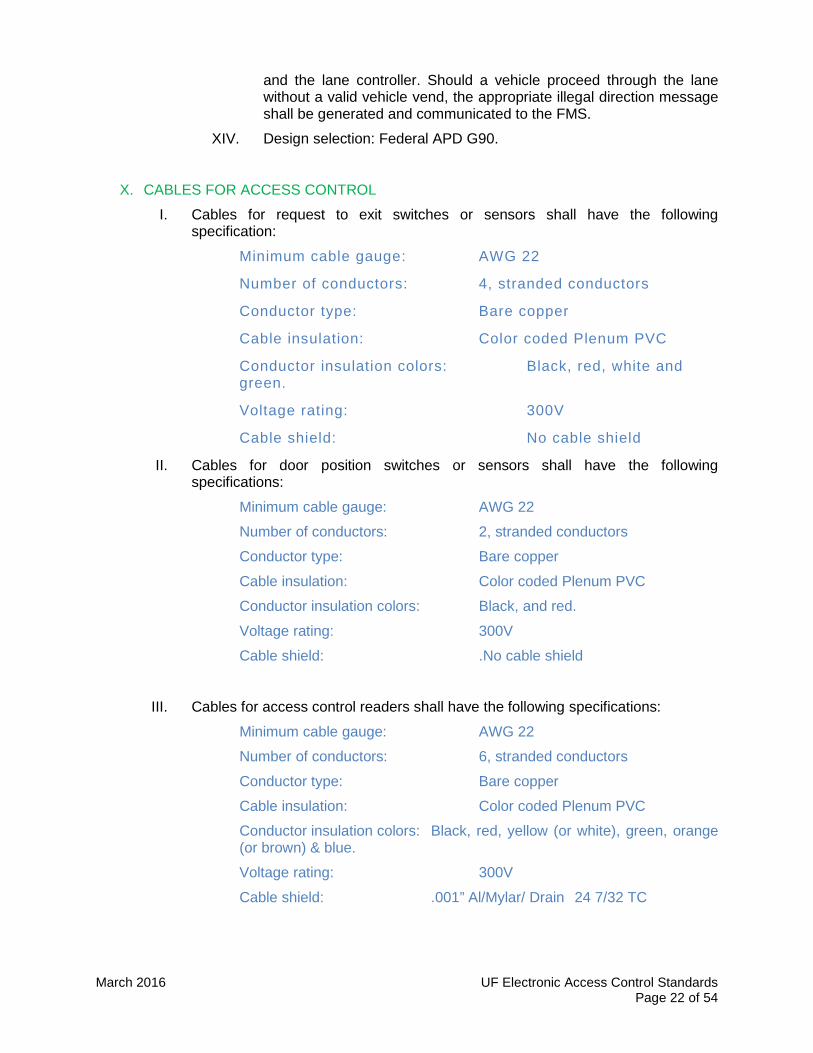
X. CABLES FOR ACCESS CONTROL
I. Cables for request to exit switches or sensors shall have the following specification:
Minimum cable gauge: AWG 22
Number of conductors: 4, stranded conductors
Conductor type: Bare copper
Cable insulation: Color coded Plenum PVC
Conductor insulation colors: Black, red, white and green.
Voltage rating: 300V
Cable shield: No cable shield
II. Cables for door position switches or sensors shall have the following specifications:
Minimum cable gauge: AWG 22
Number of conductors: 2, stranded conductors
Conductor type: Bare copper
Cable insulation: Color coded Plenum PVC
Conductor insulation colors: Black, and red.
Voltage rating: 300V
Cable shield: .No cable shield
III. Cables for access control readers shall have the following specifications:
Minimum cable gauge: AWG 22
Number of conductors: 6, stranded conductors
Conductor type: Bare copper
Cable insulation: Color coded Plenum PVC
Conductor insulation colors: Black, red, yellow (or white), green, orange (or brown) & blue.
Voltage rating: 300V
Cable shield: .001” Al/Mylar/ Drain 24 7/32 TC
March 2016 UF Electronic Access Control Standards Page 23 of 54
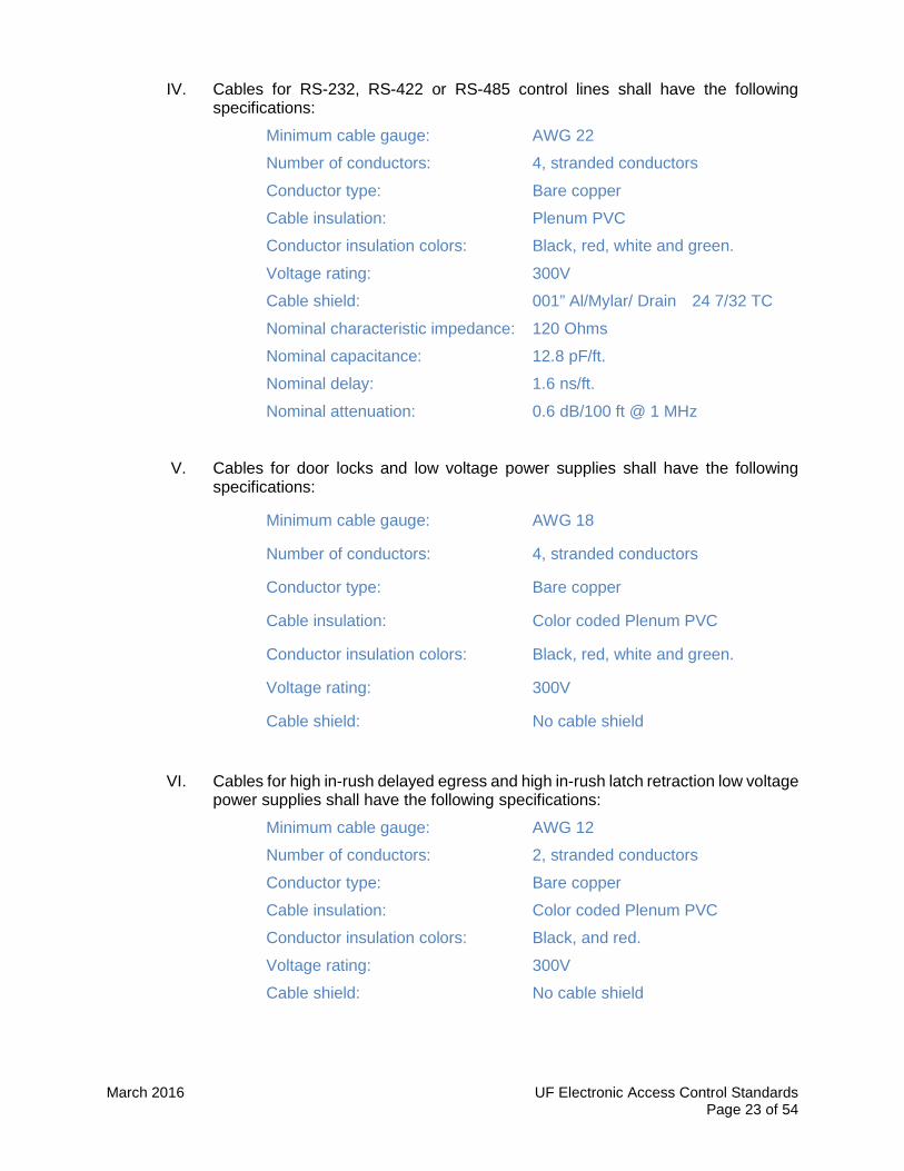
IV. Cables for RS-232, RS-422 or RS-485 control lines shall have the following specifications:
Minimum cable gauge: AWG 22
Number of conductors: 4, stranded conductors
Conductor type: Bare copper
Cable insulation: Plenum PVC
Conductor insulation colors: Black, red, white and green.
Voltage rating: 300V
Cable shield: 001” Al/Mylar/ Drain 24 7/32 TC
Nominal characteristic impedance: 120 Ohms
Nominal capacitance: 12.8 pF/ft.
Nominal delay: 1.6 ns/ft.
Nominal attenuation: 0.6 dB/100 ft @ 1 MHz
V. Cables for door locks and low voltage power supplies shall have the following specifications:
Minimum cable gauge: AWG 18
Number of conductors: 4, stranded conductors
Conductor type: Bare copper
Cable insulation: Color coded Plenum PVC
Conductor insulation colors: Black, red, white and green.
Voltage rating: 300V
Cable shield: No cable shield
VI. Cables for high in-rush delayed egress and high in-rush latch retraction low voltage power supplies shall have the following specifications:
Minimum cable gauge: AWG 12
Number of conductors: 2, stranded conductors
Conductor type: Bare copper
Cable insulation: Color coded Plenum PVC
Conductor insulation colors: Black, and red.
Voltage rating: 300V
Cable shield: No cable shield
March 2016 UF Electronic Access Control Standards Page 24 of 54
VII. Cable gauge: All cable gauges shall be estimated as to allow a maximum of 5% voltage drop from the source to the load. Sizes given previously are only minimum gauges accepted. The contractor shall always estimate proper values.
VIII. Cable jackets: All cable jackets shall be suitable for the environment on which the cables will be installed. Use cable jackets with water-blocking material when installed in underground conduits
IX. Acceptable manufacturers: Honeywell, Belden, Alpha Wire Company, General Cable and West Penn Wire.
X. UTP Category cables and fiber optic cables: for specifications on all UTP paired category cables and fiber optic cables the contractor shall follow all requirements on UF Telecommunications Standards (http://net-services.ufl.edu/infrastructure/).
PART 3 EXECUTION
A. SECURITY DOORS FUNCTIONALITY
V. The following paragraphs describe the expected functionality of the typical security doors. The Contractor shall use this description to draw the one line diagrams part of the shop drawings as described in Part 1 of this specification. The contractor shall make sure the proposed wiring for each door type produces the desired functionality for each door type.
VI. All control logic for this functionality shall be accomplished through local input/output events or with relay and timer logic when function cannot be accommodated with the Lenel hardware or software. Global events to accomplish these requirements are not allowed.
NOTE TO DESIGNER OR CONSULTANTS: Designer or consultants shall associate each security door to one of the following door types. If the desired functionality is not indicated in any of these types, the designer or consultant shall contact PPD-ITS to develop an additional type if posable.
March 2016 UF Electronic Access Control Standards Page 25 of 54
VII. DOOR TYPE DE-1 (Single, emergency-only exit with delayed egress, non-ADA)
VII. Door type: Single leaf, non-ADA
VIII. Door mode: Emergency only.
IX. Devices on secured side: By door hardware contractor: One (1) power transfer, one (1) UL listed delayed egress panic device, one (1) door closer, and one (1) High inrush power supply and fire interface board (if high inrush device is used)
X. By security contractor: One (1) Door position switch, (2) available auxiliary reader board input connections for door status and delayed egress alarm indication, (1) auxiliary reader board output relay connection from Access Control System to reset the delayed egress panic device remotely.
XI. By fire alarm contractor: A Form-C relay for fire alarm release located in security room or telecom room and interfaced with the panic devices power supply.
XII. Devices on unsecured side: By door hardware contractor: None.
XIII. By security contractor: None.
XIV. Door operation: From the secured side, after pressing the panic device for more than 3 seconds the panic device shall go into an irreversible process that unlocks the door after 30 seconds. The door shall be opened by mechanical means by pressing the panic bar after the 30 seconds.
XV. From the unsecured side, the door cannot be opened.
XVI. Key override: Key override will be provided in the built-in key switch located as part of the panic devices.
XVII. Fire alarm release: The door shall be unlocked immediately upon activation of the sprinkler system, a heat detector or no more than 2 smoke detectors in the building.
XVIII. Alarm reset and door relock: Panic device shall be reset and re-armed after momentary activation of the key switch. This same action shall be possible from a single click command from any access control workstation with access to this door.
XIX. Reported Alarms:
1. Door forced open.
2. Irreversible process started at the exit device.

March 2016 UF Electronic Access Control Standards Page 26 of 54
VIII. DOOR TYPE DE-10 (Double, emergency-only exit with delayed egress, non-ADA)
XX. Door type: Double leaf, non-ADA
XXI. Door mode: Emergency only
XXII. Devices on secured side: By door hardware contractor: Two (2) power transfer, two (2) door closers, two (2) UL listed delayed egress panic device, and one (1) High inrush power supply and fire interface board (if high inrush devices are used)
XXIII. By security contractor: Two (2) Door position switch, (2) available auxiliary reader board input connections for door status and delayed egress alarm indication (door status and egress alarm for both doors are wired as a pair of inputs), two (2) auxiliary reader board output relay connections from Access Control System to reset the delayed egress panic devices remotely.
XXIV. By fire alarm contractor: A Form-C relay for fire alarm release located in security room or telecom room and interfaced with the panic devices power supply.
XXV. Devices on unsecured side: By door hardware contractor: None.
XXVI. By security contractor: None.
XXVII. Door operation: From the secured side, after pressing any of the panic devices for more than 3 seconds both panic devices shall go into an irreversible process that unlocks both leaves after 30 seconds. Door shall be opened by mechanical means by pressing the panic bar after the 30 seconds.
XXVIII. From the unsecured side, the door cannot be opened.
XXIX. Key override: Key override will be provided in the built-in key switch located as part of the panic devices.
XXX. Fire alarm release: Both leaves shall be unlocked immediately upon activation of the sprinkler system, a heat detector or no more than 2 smoke detectors in the building.
XXXI. Alarm reset and door relock: Panic devices shall be reset and re-armed after momentary activation of the key switch. This same action shall be
March 2016 UF Electronic Access Control Standards Page 27 of 54
possible from a single click command from any access control workstation with access to this door
XXXII. Reported Alarms:
1. Door forced open, either leaf as one alarm.
2. Irreversible process started at the exit device, either leaf as one alarm.
IX. DOOR TYPE CDE-1 (Single controlled entry/exit (read in/read out) with delayed egress, non-ADA)
XXXIII. Door type: Single leaf, non-ADA
XXXIV. Door mode: Emergency and operational door.
XXXV. Devices on secured side: By door hardware contractor: One (1) power transfer, one (1) door closer, one (1) UL listed delayed egress panic device and one (1) High inrush power supply and fire interface board (if high inrush devices are used)
XXXVI. By security contractor: One (1) reader with keypad, one (1) door position switch, two (2) available auxiliary reader board input connections for door status and delayed egress alarm indication, (1) auxiliary reader board output relay connections from Access Control System to reset the delayed egress panic devices remotely.
XXXVII. By fire alarm contractor: A Form-C relay for fire alarm release located in security room or telecom room and interfaced with the panic devices power supply.
XXXVIII. Devices on unsecured side: By door hardware contractor: One (1) Electrified trim with a momentary override key cylinder for panic device. The trim shall not have the ability to be mechanically put into an unlocked condition with the key removed.
XXXIX. By security contractor: One (1) reader as indicated in floor plans.
XL. Door operation: From the secured side, Door shall also be opened by mechanical means after a valid transaction at the reader without delay and without setting off any alarms. Door alarms shall be bypassed for a fixed period of time. Alternately, after pressing the panic device for more than 3 seconds the panic device shall go into an irreversible process that sounds an audible alarm and unlocks the door after 30 seconds. Door shall be opened by mechanical means by pressing the panic bar after the 30 seconds.
XLI. From the unsecured side, the door shall be opened by mechanical means after a valid transaction at the reader or a momentary request to exit
March 2016 UF Electronic Access Control Standards Page 28 of 54
signal causing the trim to be released. Door alarms shall be bypassed for a fixed period of time.
XLII. Key override: Door Trim: The use of a valid key in the lock’s cylinder shall momentarily unlock the door, allow the door to be opened and generate a door forced open alarm. The trim may not be mechanically put into an unlocked condition with the key removed.
XLIII. Delayed egress device: Key override will be provided in the built-in key switch located as part of the panic devices.
XLIV. Fire alarm release: The door shall be unlocked immediately upon activation of the sprinkler system, a heat detector or no more than 2 smoke detectors in the building.
XLV. Alarm reset and door relock: Panic device shall be reset after a valid credential is presented and a valid function code is entered at the reader’s keypad. This same action shall be possible from a single click command from any access control workstation with access to this door.
XLVI. Reported Alarms:
1. Door forced open.
2. Irreversible process started at the exit device.
3. Invalid, lost or stolen card presented at the reader.
X. DOOR TYPE CDE-10 (Double controlled entry/exit (read in/read out) with delayed egress, non-ADA)
XLVII. Door type: Double leaf, non-ADA
XLVIII. Door mode: Emergency and operational door.
XLIX. Devices on secured side: By door hardware contractor: Two (2) power transfer, two (2) door closers, one (2) UL listed delayed egress panic device and one (1) high inrush power supply and fire interface board (if high inrush devices are used)
L. By security contractor: One (1) reader with keypad, two (2) Door position switch, two (2) available auxiliary reader board input connections for door status and delayed egress alarm indication (door status and egress alarm for both doors are wired as a pair of inputs), two (2) auxiliary reader board

March 2016 UF Electronic Access Control Standards Page 29 of 54
output relay connections from Access Control System to reset the delayed egress panic devices remotely
LI. By fire alarm contractor: A Form-C relay for fire alarm release located in security room or telecom room and interfaced with the panic devices power supply.
LII. Devices on unsecured side: By door hardware contractor: One (1) Electrified trim with a momentary override key cylinder for panic device. The trim shall not have the ability to be mechanically put into an unlocked condition with the key removed.
LIII. By security contractor: One (1) reader.
LIV. Door operation: From the secured side, Door shall also be opened by mechanical means after a valid transaction at the reader without delay and without setting off any alarms. Door alarms shall be bypassed for a fixed period of time. Alternately, after pressing the panic device for more than 3 seconds the panic device shall go into an irreversible process that sounds an audible alarm and unlocks the door after 30 seconds. Door shall be opened by mechanical means by pressing the panic bar after the 30 seconds.
LV. From the unsecured side, the door shall be opened by mechanical means after a valid transaction at the reader or a momentary request to exit signal causing the trim to be released. Door alarms shall be bypassed for a fixed period of time.
LVI. Key override: Door Trim: The use of a valid key in the lock’s cylinder shall momentarily unlock the door, allow the door to be opened and generate a door forced open alarm. The trim may not be mechanically put into an unlocked condition with the key removed.
LVII. Delayed egress device: Key override will be provided in the built-in key switch located as part of the panic devices.
LVIII. Fire alarm release: The door shall be unlocked immediately upon activation of the sprinkler system, a heat detector or no more than 2 smoke detectors in the building.
LIX. Alarm reset and door relock: Panic device shall be reset after a valid credential is presented and a valid function code is entered at the
March 2016 UF Electronic Access Control Standards Page 30 of 54
reader’s keypad. This same action shall be possible from a single click command from any access control workstation with access to this door.
LX. Reported Alarms:
LXI. 1. Door forced open.
LXII. 2. Irreversible process started at the exit device.
LXIII. 3. Invalid, lost or stolen card presented at the reader.
XI. DOOR TYPE C-1 (Single, controlled entry with electric trim, free exit, emergency and operational, non-ADA)
LXIV. Door type: Single leaf, non-ADA
LXV. Door mode: Emergency and Operational door.
LXVI. Devices on secured side: By door hardware contractor: One (1) power transfer, one (1) panic device with request to exit switch and without device dogging, one (1) door closer.
LXVII. By security contractor: One (1) Door position switch.
LXVIII. Devices on unsecured side: By door hardware contractor: One (1) Electrified trim with a momentary override key cylinder for panic device. The trim shall not have the ability to be mechanically put into an unlocked condition with the key removed.
LXIX. By security contractor: One (1) reader.
LXX. Door operation: From the secured side, the door shall be opened by mechanical means by pressing the panic bar. Activation of the built-in request to exit switch in the panic bar shall bypass all door alarms for a fixed period of time.
LXXI. From the unsecured side, the door shall be unlocked by releasing the lock trim after a valid transaction at the reader. Door alarms shall be bypassed for a fixed period of time.
LXXII. Key override: The use of a valid key in the lock’s cylinder shall momentarily unlock the door, allow the door to be opened and generate a

March 2016 UF Electronic Access Control Standards Page 31 of 54
door forced open alarm. The trim may not be mechanically put into an unlocked condition with the key removed.
LXXIII. Fail mechanism: The door lock shall be fail-secure.
LXXIV. Reported Alarms:
1. Door forced open.
2. Invalid, lost or stolen card presented at the reader.
XII. DOOR TYPE C-10 (Double, controlled entry with single electric trim and no trim on second leaf, free exit, emergency and operational, non-ADA)
LXXV. Door type: Double leaf, one leaf active for entry, both leaves active for exit. Non-ADA
LXXVI. Door mode: Emergency and Operational door.
LXXVII. Devices on secured side: By door hardware contractor: Two (1) power transfer, two (2) panic devices with request to exit switch and without device dogging, two (2) door closers.
LXXVIII. By security contractor: Two (2) Door position switches.
LXXIX. Devices on unsecured side: By door hardware contractor: One (1) Electrified trim with a momentary override key cylinder for panic device. Trim shall not have the capability of being mechanically put into an unlocked condition with the key removed
LXXX. By security contractor: One (1) reader.
LXXXI. Door operation: From the secured side, the door shall be opened by mechanical means by pressing the panic bar (either leaf). Activation of the built-in request to exit switch in either panic bar shall bypass all door alarms for a fixed period of time. From the unsecured side, the door shall be unlocked by releasing the trim after a valid transaction at the reader. Door alarms shall be bypassed for a fixed period of time.
LXXXII. Key override: The use of a valid key in the lock’s cylinder shall momentarily unlock the door, allow the door to be opened and generate a door forced open alarm. The trim may not be mechanically put into an unlocked condition with the key removed.
LXXXIII. Fail mechanism: Door lock shall be fail-secure.
March 2016 UF Electronic Access Control Standards Page 32 of 54
LXXXIV. Reported Alarms:
1. Door forced open, either leaf as one alarm.
2. Invalid, lost or stolen card presented at the reader.
XIII. DOOR TYPE C-11 (Double, controlled entry with electric trim on both leaves, free exit, emergency and operational, non-ADA)
LXXXV. Door type: Double leaf, both leaves active for entry and exit. Non-ADA
LXXXVI. Door mode: Emergency and Operational door.
LXXXVII. Devices on secured side: By door hardware contractor: Two (2) power transfer, two (2) panic devices with request to exit switch and without device dogging, two (2) door closers.
LXXXVIII. By security contractor: Two (2) door position switches.
LXXXIX. Devices on unsecured side: By door hardware contractor: One (1) electrified trim with a momentary override key cylinder and one (1) electrified trim with no key cylinder both trim are for panic devices. Either trim shall not have the capability of being mechanically put into an unlocked condition with the key removed.
XC. By security contractor: One (1) reader
XCI. Door operation: From the secured side, the door shall be opened by mechanical means by pressing the panic bar (either leaf). Activation of the built-in request to exit switch in either panic bar shall bypass all door alarms for a fixed period of time. From the unsecured side, the door shall be unlocked by releasing the trim after a valid transaction at the reader. Door alarms shall be bypassed for a fixed period of time.
XCII. Key override: The use of a valid key in the lock’s cylinder shall momentarily unlock the door, allow the door to be opened and generate a door forced open alarm. The trim may not be mechanically put into an unlocked condition with the key removed.
XCIII. Fail mechanism: Door lock shall be fail-secure.
XCIV. Reported Alarms:
1. Door forced open, either leaf as one alarm.
2. Invalid, lost or stolen card presented at the reader.

March 2016 UF Electronic Access Control Standards Page 33 of 54
XIV. DOOR TYPE EO-3 (Single, controlled entry with electric latch, free exit, emergency and operational, non-ADA)
XCV. Door type: Single leaf, non-ADA
XCVI. Door mode: Emergency and Operational door.
XCVII. Devices on secured side: By door hardware contractor: One (2) Power transfer, one (1) door closers, one (1) electrified latch retraction panic device with built in REX switch, (1) High inrush power supply and fire interface board (if high inrush device is used)
XCVIII. By security contractor: One (1) Door position switch.
XCIX. Devices on unsecured side: By door hardware contractor: One (1) trim with a momentary override key cylinder for panic devices. Trim shall not have the capability of being mechanically put into an unlocked condition with the key removed.
C. By security contractor: One (1) reader, as indicated in floor plans.
CI. Door operation: From the secured side, the door shall be opened by mechanical means by pressing the panic bar. Activation of the built-in request to exit switch in the panic bar shall bypass all door alarms for a fixed period of time. From the unsecured side, the door shall be unlocked by retracting the latch in the lock after a valid transaction at the reader. Door alarms shall be bypassed for a fixed period of time.
CII. Key override: The use of a valid key in the lock’s cylinder (if present) shall unlock the door and allow the door to be opened, but if used without a valid reader transaction, a door forced open alarm shall be initiated. The lock may not be mechanically put into an unlocked condition with the key removed.
CIII. Fail mechanism: Door lock shall be fail-secure.
CIV. Reported Alarms:
CV. 1. Door forced open.
CVI. 2. Invalid, lost or stolen card presented at the reader.
March 2016 UF Electronic Access Control Standards Page 34 of 54
XV. DOOR TYPE EO-4 (Double controlled entry with electric latch, free exit, emergency and operational, non-ADA)
CVII. Door type: Double leaf, one leaf active for entry, both leaves active for exit. Non-ADA
CVIII. Door mode: Emergency and Operational door.
CIX. Devices on secured side: By door hardware contractor: Two (2) Power transfers, two (2) panic device with REX switch and one of the panic devices with electric latch retraction
CX. By security contractor: Two (2) Door position switch.
CXI. Devices on unsecured side: By door hardware contractor: None.
CXII. By security contractor: One (1) reader, as indicated in floor plans.
CXIII. Door operation: From the secured side, the door shall be opened by mechanical means by pressing the panic bar (either leaf). Activation of the built-in request to exit switch in either panic bar shall bypass all door alarms for a fixed period of time. From the unsecured side, the door shall be unlocked by retracting the latch in the lock after a valid transaction at the reader. Door alarms shall be bypassed for a fixed period of time.
CXIV. Key override: The use of a valid key in the lock’s cylinder (if present) shall unlock the door and allow the door to be opened,

March 2016 UF Electronic Access Control Standards Page 35 of 54
but if used without a valid reader transaction, a door forced open alarm shall be initiated.
CXV. Fail mechanism: Door lock shall be fail-secure if door is exterior door and fail-safe if door is interior.
CXVI. Reported Alarms:
CXVII. 1. Door forced open, either leaf as one alarm.
CXVIII. 2. Invalid, lost or stolen card presented at the reader.
CXIX. 3. Door held open, either leaf as one alarm. Contractor to coordinate with the UF PPD ITS held open time on a per door basis.
XVI. DOOR TYPE CA-1 (Single leaf, single reader, double mode emergency and operational, ADA)
CXX. Door type: Single leaf, automatic door. ADA compliant
CXXI. Door mode: Emergency and Operational door. Door has two operating modes, free mode and controlled mode. Modes shall be activated by a schedule.
CXXII. Devices on secured side: By door hardware contractor: One (1) power transfer, one (1) latch retraction panic device with request to exit switch and without device dogging, one (1) automatic door operator.
CXXIII. By security contractor: One (1) door position switch and one (1) hardwired ADA automatic door operator push button.
CXXIV. Devices on unsecured side: By door hardware contractor: One (1) trim with a momentary override key cylinder trim for panic devices. Trim shall

March 2016 UF Electronic Access Control Standards Page 36 of 54
not have the capability of being mechanically put into an unlocked condition with the key removed.
CXXV. By security contractor: One (1) hardwired ADA automatic door operator push button.
CXXVI. Door operation: Unlocked Mode
CXXVII. (Note: The electric latch in the panic device shall be retracted during this mode)
CXXVIII. From the secured side, the door shall be opened by mechanical means by pressing the panic bar or automatically by activation of the ADA push button. The door will only be opened for a fixed period of time.
CXXIX. From the unsecured side, the door shall be opened manually by pulling the outside trim or automatically by activation of the ADA push button. The door will only be opened for a fixed period of time.
CXXX. Door operation: Card Only Mode
CXXXI. From the secured side, the door shall be opened by mechanical means by pressing the panic bar or automatically by activation of the ADA push button. The activation of the ADA button will unlock the door, issue a request to exit event and trigger the ADA operator to open the door for a fixed period of time.
CXXXII. From unsecured side, a valid transaction at the reader shall retract the latch in the panic device and enable the ADA operator push button for a fixed momentary period of time. During this time the door can be opened manually by pulling the outside trims or automatically by activation of the ADA push button. The door will only be opened for a fixed period of time.
CXXXIII. Key override: The use of a valid key in the lock’s cylinder shall momentarily unlock the door, allow the door to be opened and generate a door forced open alarm. The trim may not be mechanically put into an unlocked condition with the key removed.
CXXXIV. Fail mechanism: Door lock shall be fail-secure.
CXXXV. Reported Alarms: Card Only Mode:
1. Door forced open.
2. Invalid, lost or stolen card presented at the reader.
March 2016 UF Electronic Access Control Standards Page 37 of 54
XVII. DOOR TYPE CA-10 (Double leaf, single reader, double mode emergency and operational, ADA)
CXXXVI. Door type: Double leaf, automatic door. ADA compliant
CXXXVII. Door mode: Emergency and Operational door. Door has two operating modes, free mode and controlled mode. Modes shall be activated by a schedule.
CXXXVIII. Devices on secured side: By door hardware contractor: Two (1) power transfers, two (2) latch retraction panic devices with request to exit switches and without device dogging, one (1) automatic double door operator.
CXXXIX. By security contractor: Two (2) door position switch and one (1) hardwired ADA automatic door operator push button.
CXL. Devices on unsecured side: By door hardware contractor: One (1) trim with a momentary override key cylinder and one (1) trim with no key cylinder both trim are for panic devices. Either trim shall not have the capability of being mechanically put into an unlocked condition with the key removed.
CXLI. By security contractor: One (1) hardwired ADA automatic door operator push button.
CXLII. Door operation: Unlocked Mode
CXLIII. (Note: The electric latches in the panic devices shall be retracted during this mode)
CXLIV. From the secured side, the doors shall be opened by mechanical means by pressing either panic bar or automatically by activation of the ADA push button. The doors will only be opened for a fixed period of time.
CXLV. From the unsecured side, the doors shall be opened manually by pulling the outside trims or automatically by activation of the ADA push button. The doors will only be opened for a fixed period of time.
CXLVI. Door operation: Card Only Mode
CXLVII. From the secured side, the door shall be opened by mechanical means by pressing either panic bar or automatically by activation of the ADA push button. The activation of the ADA button will unlock both doors, issue a request to exit event and trigger the ADA operator to open the door for a fixed period of time.
CXLVIII. From unsecured side, a valid transaction at the reader shall retract the latches in the panic devices and enable the ADA operator push button for a fixed momentary period of time. During this time the door can be opened manually by pulling the outside trims or automatically by
March 2016 UF Electronic Access Control Standards Page 38 of 54
activation of the ADA push button. The doors will only be opened for a fixed period of time.
CXLIX. Key override: The use of a valid key in the lock’s cylinder shall momentarily unlock the door, allow the door to be opened and generate a door forced open alarm. The trim may not be mechanically put into an unlocked condition with the key removed.
CL. Fail mechanism: Door lock shall be fail-secure.
CLI. Reported Alarms: Card Only Mode:
1. Door forced open.
2. Invalid, lost or stolen card presented at the reader.
XVIII. DOOR TYPE CA-R3 (Double leaf, three reader, double mode emergency and operational, ADA)
CLII. Door type: Double leaf, automatic door. ADA compliant
CLIII. Door mode: Emergency and Operational door. Door has two operating modes, free mode and controlled mode. Modes shall be activated by a schedule.
CLIV. Devices on secured side: By door hardware contractor: Two (1) power transfers, two (2) latch retraction panic devices with request to exit switches and without device dogging, one (1) automatic double door operator.
CLV. By security contractor: One (1) long range proximity reader, two (2) door position switch and one (1) hardwired ADA automatic door operator push button.
CLVI. Devices on unsecured side: By door hardware contractor: One (1) trim with a momentary override key cylinder and one (1) trim with no key cylinder both trim are for panic devices. Either trim shall not have the
March 2016 UF Electronic Access Control Standards Page 39 of 54
capability of being mechanically put into an unlocked condition with the key removed.
CLVII. By security contractor: One (1) card reader, one (1) long range proximity reader, one (1) hardwired ADA automatic door operator push button.
CLVIII. Door operation: Unlocked Mode
CLIX. (Note: The electric latches in the panic devices shall be retracted during this mode)
CLX. From the secured side, the door shall be opened by mechanical means by pressing the panic bar (either leaf) or automatically by a valid transaction at the long range proximity reader or activation of the ADA push button. The doors will only be opened for a fixed period of time.
CLXI. From the unsecured side, the door shall be opened manually by pulling the outside trims or automatically by a valid transaction at the long range proximity reader or activation of the ADA push button. The doors will be opened for a fixed period of time.
CLXII. Door operation: Card Only Mode
CLXIII. From the secured side, the door shall be opened by mechanical means by pressing either panic bar or automatically by a valid transaction at the long range proximity reader or activation of the ADA push button. The activation of the ADA button will unlock both doors, issue a request to exit event and trigger the ADA operator to open the door for a fixed period of time.
CLXIV. From unsecured side, a valid transaction at the reader shall retract the latches in the panic devices and enable the ADA operator push button for a fixed momentary period of time. During this time the door can be opened manually by pulling the outside trims or automatically by a valid transaction at the long range proximity reader or activation of the ADA push button. The doors will only be opened for a fixed period of time.
CLXV. Reported Alarms (controlled mode):
CLXVI. 1. Door forced open, either leaf as one alarm. Invalid, lost or stolen card presented at the reader.
CLXVII. 2. Door held open, either leaf as one alarm. Contractor to coordinate with the UF PPD ITS held open time on a per door basis.
Key override: The use of a valid key in the lock’s
cylinder shall momentarily unlock the door, allow the door to be opened and generate a door forced open alarm. The trim may not be
March 2016 UF Electronic Access Control Standards Page 40 of 54
mechanically put into an unlocked condition with the key removed.
Fail mechanism: Door lock shall be fail-secure.
Reported Alarms: Card Only Mode:
1. Door forced open. 2. Invalid, lost or stolen card presented
at the reader.
XIX. DOOR TYPE CM-1 (Single controlled entry with mortise lock, free exit, non-emergency)
CLXVIII. Door type: Single leaf
CLXIX. Door mode: Operational door.
CLXX. Devices on secured side: By door hardware contractor: One (1) Power transfer, one (1) electrified mortise lock with request to exit switch built in and one (1) door closer
CLXXI. By security contractor: One (1) Door position switch.
CLXXII. Devices on unsecured side: By door hardware contractor: None.
CLXXIII. By security contractor: One (1) reader
CLXXIV. Door operation: From the secured side, the door shall be opened by mechanical means using the mortise lock handle. Activation of the built-in request to exit switch in the lock shall bypass all door alarms for a fixed period of time.
CLXXV. From the unsecured side, the door shall be unlocked by releasing the lock after a valid transaction at the reader. Door alarms shall by bypassed for a fixed period of time.
CLXXVI. Key override: The use of a valid key in the lock’s cylinder shall unlock the door and allow the door to be opened, but, a door forced open alarm shall be initiated.
CLXXVII. Fail mechanism: Door lock shall be fail-secure.
CLXXVIII. Reported Alarms:
CLXXIX. 1. Door forced open.
CLXXX. 2. Invalid, lost or stolen card presented at the reader.

March 2016 UF Electronic Access Control Standards Page 41 of 54
XX. DOOR TYPE CM-10 (Double controlled entry with mortise lock, free exit, non-emergency)
CLXXXI. Door type: Double leaf, one active, one inactive
CLXXXII. Door mode: Operational door.
CLXXXIII. Devices on secured side: By door hardware contractor: One (1) Power transfer, one (1) electrified mortise lock with request to exit switch built in, two (2) door contacts, two (2) door closers and one (1) set of automatic top and bottom pins for the inactive leaf.
CLXXXIV. By security contractor: Two (2) Door position switches.
CLXXXV. Devices on unsecured side: By door hardware contractor: None.
CLXXXVI. By security contractor: One (1) reader.
CLXXXVII. Door operation: From the secured side, one leaf shall be opened by mechanical means using the electrified mortise lock. Activation of the built-in request to exit switch in the lock shall bypass all door alarms for a fixed period of time. Second leaf shall only be opened by mechanical means after other leaf is opened.
CLXXXVIII. From the unsecured side, the active leaf shall be unlocked by releasing the lock after a valid transaction at the reader. Door alarms shall by bypassed for a fixed period of time.
CLXXXIX. Key override: The use of a valid key in the lock’s cylinder shall unlock the door and allow the door to be opened, but a door forced open alarm shall be initiated.
CXC. Fail mechanism: Door lock shall be fail-secure.
CXCI. Reported Alarms:
CXCII. 1. Door forced open.
CXCIII. 2. Invalid, lost or stolen card presented at the reader.
March 2016 UF Electronic Access Control Standards Page 42 of 54
XXI. DOOR TYPE CM-1R2 (Single controlled entry with mortise lock, entry/exit (read in/read out) free exit, non-emergency)
CXCIV. Door type: Single leaf
CXCV. Door mode: Operational door.
CXCVI. Devices on secured side: By door hardware contractor: One (1) Power transfer, one (1) electrified mortise lock with both handles locking and cylinder control on both sides and one (1) door closer
CXCVII. By security contractor: One (1) reader and one (1) Door position switch.
CXCVIII. Devices on unsecured side: By door hardware contractor: None.
CXCIX. By security contractor: One (1) reader
CC. Door operation: From the secured side, the door shall be unlocked by releasing the lock after a valid transaction at the reader. Door alarms shall by bypassed for a fixed period of time.
CCI. From the unsecured side, the door shall be unlocked by releasing the lock after a valid transaction at the reader. Door alarms shall by bypassed for a fixed period of time.
CCII. Key override: The use of a valid key in either of the lock’s cylinders shall unlock the door and allow the door to be opened, but, a door forced open alarm shall be initiated.
CCIII. Fail mechanism: Door lock shall be fail-secure.
CCIV. Reported Alarms:
CCV. 1. Door forced open.
CCVI. 2. Invalid, lost or stolen card presented at the reader.

March 2016 UF Electronic Access Control Standards Page 43 of 54
XXII. DOOR TYPE M-1RX (Single monitored door with request to exit)
CCVII. Door type: Single leaf
CCVIII. Door mode: Monitored door.
CCIX. Devices on secured side: By door hardware contractor: One (1) Power transfer, one (1) mortise lock with request to exit switch built in.
CCX. By security contractor: One (1) Door position switch and one reader interface port
CCXI. Devices on unsecured side: By door hardware contractor: None.
CCXII. By security contractor: None.
CCXIII. Door operation:
CCXIV. From the secured side, the door shall be opened by mechanical means using the mortise lock. Activation of the built-in request to exit switch in the lock shall bypass all door alarms for a fixed period of time.
CCXV. From the unsecured side, the use of a valid key in the lock’s cylinder shall unlock the door and allow the door to be opened, but, a door forced open alarm shall be initiated.
CCXVI. Reported Alarms:
CCXVII. 1. Door forced open from unsecure side.
XXIII. DOOR TYPE M-10RX (Dual monitored door with request to exit)
CCXVIII. Door type: Double leaf
CCXIX. Door mode: Monitored door.
CCXX. Devices on secured side: By door hardware contractor: One (1) Power transfer, one (1) mortise lock with request to exit switch built in.

March 2016 UF Electronic Access Control Standards Page 44 of 54
CCXXI. By security contractor: One (1) reader interface port and two (2) Door position switches.
CCXXII. Devices on unsecured side: By door hardware contractor: None.
CCXXIII. By security contractor: None.
CCXXIV. Door operation: From the secured side, the door shall be opened by mechanical means using the mortise lock. Activation of the built-in request to exit switch in the lock shall bypass all door alarms for a fixed period of time.
CCXXV. From the unsecured side, the use of a valid key in the lock’s cylinder shall unlock the door and allow the door to be opened, but, a door forced open alarm shall be initiated.
CCXXVI. Reported Alarms:
1. Door forced open from unsecure side (both leaves reporting as one alarm).
XXIV. DOOR TYPE M-1 (Single monitored door)
CCXXVII. Door type: Single leaf
CCXXVIII. Door mode: Monitored door.
CCXXIX. Devices on secured side: By door hardware contractor: None.
CCXXX. By security contractor: One (1) aux input for door status, and one (1) Door position switch.
CCXXXI. Devices on unsecured side: By door hardware contractor: None.
CCXXXII. By security contractor: None.
CCXXXIII. Door operation: From the secured side or the unsecured side, the door shall be opened by mechanical means using the door lock but a door forced open alarm shall be initiated.
CCXXXIV. Reported Alarms:
1. Door opened alarm
.
March 2016 UF Electronic Access Control Standards Page 45 of 54
XXV. DOOR TYPE M-10 (Double monitored door)
CCXXXV. Door type: Double leaf
CCXXXVI. Door mode: Monitored door.
CCXXXVII. Devices on secured side: By door hardware contractor: None.
CCXXXVIII. By security contractor: one (1) aux input for door status and two (2) door position switches (wire in series).
CCXXXIX. Devices on unsecured side: By door hardware contractor: None.
CCXL. By security contractor: None.
CCXLI. Door operation: From the secured side or the unsecured side, the door shall be opened by mechanical means using the door lock but a door forced open alarm shall be initiated.
CCXLII. Reported Alarms:
1. Door opened alarm (both leaves reporting as one alarm)

March 2016 UF Electronic Access Control Standards Page 46 of 54
XXVI. DOOR TYPE G-1 (Reader controlled entry gate with loop controlled exit)
CCXLIII. Door type: Rolling vehicular gate
CCXLIV. Door mode: Scheduled and controlled.
CCXLV. Devices on secured side: By gate contractor: Rolling gate, gate operator with gate position status, secure side safety loop, DPDT optical safety detector exit loop and DPDT exit loop detector.
CCXLVI. By security contractor, Request to exit Input, gate status input and auxiliary input for Photo detector.
CCXLVII. Devices on unsecured side: By gate contractor, unsecure side safety loop detector
CCXLVIII. By security contractor, one (1) pedestal with a card readers
CCXLIX. Door operation: From the secured side (reverse entry side), the gate shall be opened by activation of the exit loop. Gate alarms shall be by-passed for a fixed period of time.
CCL. From the unsecured side (entry side), the gate shall be rolled opened for a fixed period of time after a valid transaction at the reader. Gate alarms shall be by-passed for a fixed period of time.
CCLI. Activation of either safety loop optical detector shall stop the gate. The gate shall close once the obstruction is removed.
CCLII. Reported Alarms:
1. Gate forced open..
2. Optical detector blocked 3. Invalid, lost or stolen card presented
at the reader.
March 2016 UF Electronic Access Control Standards Page 47 of 54
XXVII. DOOR TYPE G-2 (Free exit gate)
CCLIV. Door type: Vehicular gate
CCLV. Door mode: Operational door.
CCLVI. Devices on secured side: By door hardware contractor: None.
CCLVII. By security contractor: An exit loop.
CCLVIII. Devices on unsecured side: By door hardware contractor: None.
CCLIX. By security contractor: A gate barrier with safety loops.
CCLX. Door operation:
CCLXI. From the secured side (exit side), the gate arm shall be raised for a fixed period of time after activation of the exit loop. Gate alarms shall be by-passed for a fixed period of time.
CCLXII. From the unsecured side (reverse exit side), the gate arm shall not be opened.
CCLXIII. Reported Alarms:
CCLXIV. 1. Gate barrier enclosure tamper.
CCLXV. 2. Gate held open: Barrier arm up after time opening time expired. Contractor to coordinate with the UF PPD ITS held open time on a per gate basis.
March 2016 UF Electronic Access Control Standards Page 48 of 54
XXVIII. DOOR TYPE G-3 (Controlled entry, free exit gate)
CCLXVI. Door type: Vehicular gate
CCLXVII. Door mode: Operational door.
CCLXVIII. Devices on secured side: By door hardware contractor: None.
CCLXIX. By security contractor: Exit loop.
CCLXX. Devices on unsecured side: By door hardware contractor: None.
CCLXXI. By security contractor: A gate barrier with safety loops, one (1) pedestal with a card readers as indicated in floor plans.
CCLXXII. Door operation:
CCLXXIII. From the secured side (exit side), the gate arm shall be raised for a fixed period of time after activation of the exit loop. Gate alarms shall be by-passed for a fixed period of time.
CCLXXIV. From the unsecured side (entry side), the gate arm shall be raised for a fixed period of time after a valid transaction at the reader. Gate alarms shall be by- passed for a fixed period of time.
CCLXXV. Activation of the safety loop shall not let the gate arm to come down.
CCLXXVI. Reported Alarms:
CCLXXVII. 1. Gate barrier enclosure tamper.
CCLXXVIII. 2. Invalid, lost or stolen card presented at the reader.
CCLXXIX. 3. Gate held open: Barrier arm up after opening time expired. Contractor to coordinate with the UF PPD ITS held open time on a per gate basis.

March 2016 UF Electronic Access Control Standards Page 49 of 54
B. INSTALLATION PRACTICES
I. All AC power shall be fed from the building's power source supported by an emergency backup generator where applicable. All system power supplies shall include backup batteries that will provide continuous power for a minimum of 30 minutes, maintain the battery’s charge and provide status of the battery’s failure. The source of the AC power feed shall be identified at termination point of equipment.
II. The card access system shall utilize the existing campus network using approved protocols for communications between the building controllers, client workstations and the central database server.
III. All power supplies shall be monitored for AC failure. Power supplies shall provide a Form-C relay with power loss signaling, this contact shall also be monitored. All AC fail and backup battery low alarms shall be monitored through individual alarm inputs. Series connections of multiple alarm points shall not be allowed.
IV. Any junction boxes that need to contain splices or connections shall be pre-approved by PPD-ITS. If approved, the junction box shall be equipped with a tamper switch. All junction boxes shall be clearly identified in as-built.
V. All buzzers inside card readers shall be wired to alert users of different door statuses - "Door held open" and "door forced open", for example.
VI. All inputs shall provide UL 1076 Grade A analog supervised alarm input zones to monitor and report line fault conditions (open, short, ground, or circuit fault), alarm conditions, power faults and tampers. When an alarm input is activated, the associated alarm condition shall be reported to both the ISC and subsequently to the alarm monitoring client workstation. Status LEDs shall provide information about the any supervisable access control inputs, cabinet tamper, and power fault. For each status LED, no light shall imply a "No Alarm" condition, a solid LED shall indicate an “Alarm Condition”, and a fast flash shall indicate a “Zone Fault” (open, short, ground, or circuit fault).
NOTE TO DESIGNERS OR CONSULTANTS. Control panels, power supplies and all other head-end components shall be located in a single, secured room within the building, with local access to staff. In multi-story buildings there may be equipment in such rooms on more than one floor. The room(s) selected to house the electronic access components shall not contain mechanical or elevator controls equipment. In lieu of a dedicated security room located on each floor, a Telecommunication Room, can be used with approval from PPD-ITS and UF telecommunications. All components shall be contained in enclosures, each of which shall be mounted on backboard of 4'x8' plywood ¾" thick painted grey with fireproof paint. Enclosures shall be mounted at locations and heights that ensure ease of service. Proposed locations for Lenel devices will be reviewed on a case-by-case basis. UF Health IT and UF Network Services must approve the location of any Lenel devices in their respective areas. A variance request must be submitted if the proposed location of a Lenel device is within a Telecommunications Room. The request may be approved if structured cabling is used and there is enough space, power and cooling capacity available in the room.

March 2016 UF Electronic Access Control Standards Page 50 of 54
C. WIRING METHODS
I. All proposed wire and cable shall meet or exceed the recommendations established by the equipment manufacturers, and shall comply with all state and local codes.
II. Visually inspect all wire and cable for faulty insulation prior to installation
III. Provide grommets and strain relief materials where necessary to avoid abrasion and excess tension on wire and cable.
IV. All penetrations through fire rated barriers shall be provided with appropriate fire stopping materials in accordance with NFPA requirements and local fire authority having jurisdiction.
V. Installation of all UTP Category cables and Fiber Optic cables shall be in accordance with EIA/TIA guidelines and UF Telecommunications Standards (http://net-services.ufl.edu/infrastructure/).
VI. All cable runs shall be continuous from the device to the head-end equipment. Cable splices shall not permitted without approval by PPD-ITS.
VII. All cabling runs shall be physically accessible for replacement of cables . Physically accessible is defined as by means of cable tray or conduit in which cabling can be physically re-pulled after construction. Cable that is installed in unfinished structural framing, store front framing or in any inaccessible space that will require disassembly for access will not be accepted. Failure to notify the designer/consultant of these issues, whether intentionally or by oversight may r esult in rejection of this installation method. Should this occur the contractor will be required to reinstall the cabling/raceway with a pr e-approved method that meet or exceed the requirements as specified h erein. This will be done at no additional cost to the client.
VIII. Cables of similar signal level shall be bundled together and kept physically separate from power cords, plug strips or other circuits with different potential. Exposed wire bundles or individual cables shall be neatly secured with self-clinching nylon "TY-Raps" (Thomas & Betts or equivalent). Lacing of cables shall not be permitted.
IX. Finger duct wire managers shall be used inside all equipment panels to properly dress cables.
D. IDENTIFICATION AND TAGGING
I. All cables and wires shall be clearly identified by pre-printed labels or tags at each headend termination point. The permanent markings shall clearly indicate the function and connected device’s address for all cabling and wire within a foot of the terminals. Schematic legends shall be placed inside all terminal cabinets to assist with identification of components and connections contained therein.
II. All access control panels shall include a worksheet attached to the interior of the panel in plastic envelops. This worksheet shall include the location, type of device and part number of all devices connected to the boards inside the panel. All names used to identify devices in these worksheets shall conform to the UF Standardized Hardware Naming Convention. This

March 2016 UF Electronic Access Control Standards Page 51 of 54
document can be found on the PPD website (http://www.ppd.ufl.edu/PPDITS/pdf/uflenelnamingconventions.pdf). A second copy of this worksheet shall be delivered to the UF PPD ITS as part of the as-built information.
E. ADDITIONAL CONTRACTOR RESPONSIBILITIES
I. Upon project commencement, the Contractor shall provide qualified technical personnel on-site. Personnel shall be present on each consecutive working day until the system is fully functional and ready to begin the testing phase.
II. During the installation process the contractor shall maintain an up-to-date set of as-built shop drawings, which shall always be available for review by the client and/or consultants. This set of documents should be clearly annotated with as-built data as the work is performed.
F. PROGRAMMING AND SYSTEM CONFIGURATION
I. The contractor shall assist UF PPD ITS with programming and configuration of the security management system. Programming shall include defining descriptions for access control hardware, doors, alarm monitor points, service codes, intrusion zones, door groups, alarm groups, operating sequences, camera call-ups, and the like.
II. Contractor shall maintain hard copy worksheets which fully document the system installation, programming, and configuration. Worksheets shall be kept up to date on a daily basis by contractor until final acceptance.
G. WARRANTEE
I. During the first year of service the contractor shall ensure that manufacturer-certified repair and maintenance personnel are available for Emergency Service calls twenty-four (24) hours a day, three hundred sixty five (365) days a year. The maximum on-site response time for emergency services shall not exceed four (4) hours for warranty or non-warranty issues. The contractor shall be able to perform any and all repairs to the system within 24 hours.
H. CONTRACTOR TESTING
I. The contractor shall activate all alarms and other output devices that are in the system to test for proper operation, including system power supplies A/C and backup battery notifications and all system cabinet tampers.
II. After installation and prior to termination, all wiring and cabling shall be checked and tested to ensure there are no grounds, opens, or shorts on any conductors or shields. A volt ohms meter shall be utilized for this test.

March 2016 UF Electronic Access Control Standards Page 52 of 54
Signal strength greater than 20 mega ohms shall be required to successfully complete the test.
III. All testing of UTP Category cable shall be provided in conformance with the requirements established under the UF Telecommunications Standards (http://net-services.ufl.edu/infrastructure/).
IV. The contractor shall develop a report that indicates a complete listing of all equipment and alarm monitoring points in this facility. This list shall be used as a guide during testing to ensure that all components are inspected. The personnel conducting these tests shall indicate the following information on this form:
V. Name of person conducting test
VI. Date of test
VII. Time of test
VIII. Results of test
IX. Upon successful completion of tests, the log file(s) generated by this activity shall be printed and submitted along with the testing documents, to PPD-ITS.

March 2016 UF Electronic Access Control Standards Page 53 of 54
I. PREPARATION FOR FINAL ACCEPTANCE TESTING
I. All components shall be inspected to ensure they have been properly installed, securely attached, and remain clean and unmarred.
II. All equipment shall be properly adjusted, clearly labeled, and fully operational.
III. All broken, damaged or modified items such as walls, doorframes, ceiling tiles, etc., shall be replaced or properly repaired to the satisfaction of the client.
IV. All extra or spare materials shall be delivered to PPD-ITS, as directed.
V. Test report of all system components shall be completed and available for inspection as indicated herein. A digital set of the test report shall be provided in digital format uploaded to the project SharePoint site.
VI. A digital set of Individual factory issued Equipment Manuals containing all technical information on each piece of equipment. Advertising brochures or information instructions shall not be used in lieu of technical manuals and information. Documents to be provided in digital format uploaded to the project SharePoint site.
VII. A digital set of Individual factory issued Operation Manuals containing all technical information on the system. Advertising brochures or information instructions shall not be used in lieu of technical manuals and information. Documents to be provided in digital format uploaded to the project SharePoint site.
VIII. A digital set of As-Built drawings shall be prvided. Documents to be provided in digital format uploaded to the project SharePoint site.
IX. Statement of Guarantee including date of termination, and the name/telephone number of person to be called in the event of equipment failure.
J. AS-BUILT DOCUMENTS
I. As-built documents shall be provided as part of this contract. As-built drawings shall be a complete set of AutoCAD Release 2017 floor plans drawings, riser diagrams, and wiring details indicating the layout and interconnection of the system. The original project floor plan disk shall be obtained from the consulting engineer. All cable routings and elevation of each riser cable and device terminations shall be required. All addendum information or project revisions resulting in drawing changes that occur during the construction period shall be documented and included in the as-built material. All required as-built documentation is mandatory and shall be required prior to project closeout. A complete set of prints with all changes shall be submitted to the Engineer’s for review. Upon completion of the Engineer’s review, the Contractor shall provide an updated electronic drawing files. This information must include final As-Built conditions and the Engineer’s review comments if any.
March 2016 UF Electronic Access Control Standards Page 54 of 54
K. FINAL ACCEPTANCE TESTING
I. After testing reports, as-built drawings, and required manuals have beensubmitted for review, the Contractor shall coordinate a date for FinalAcceptance Testing.
II. Testing and acceptance of this system will take place in the presence ofUF PPD ITS.
III. Acceptance of the system shall require a demonstration of all systemcomponents to evaluate their performance and reliability. Prior to this testthe system must have been online for a period of sixty (60) days, with anuptime of no less than 99%. Should a major equipment failure occur, theContractor shall replace the defective component and continue the testingperiod. Any items discovered during final inspection which require thecontractors attention, shall be promptly addressed. These items will thenbe re-inspected by the UF PPD ITS for approval.
IV. Upon the completion of acceptable Final Acceptance Testing theContractor shall submit all finalized project documentation and associatedelectronic media. Upon approval from UF PPD ITS., UF PPD ITS will issuea Letter of Completion to the Contractor indicating the date of suchcompletion. This notice will serve as Client acceptance of this system.
END OF SECTION