Embed Size (px)
Citation preview

manuale per l’installatore - 1/3tipologie d’installazione - 2/3
software handbook - 3/3
TA010976B - N. 4 del 11.11.2002
M.T.M. s.r.l.
Via La Morra, 112062 - Cherasco (Cn) - ItalyTel. ++39 0172 48681Fax ++39 0172 488237

2
INDICE
INTRODUCTIONWHAT IS THE PROGRAM FOR SEQUENT INSTALLERSTO WHOM IS THIS GUIDE ADDRESSED
USEFUL REFERENCES
1. WHAT DO YOU NEED TO START1.1 THE PERSONAL COMPUTER1.2 THE INTERFACE CABLE FOR SEQUENT INST ALLA TIONS 1.3 SOFTWARE AND HARDWARE KEY
2. SOFTWARE INSTALLATION AND HARDWARE KEY USE 2.1 “SEQUENT” SOFTW ARE INSTALLA TION ON PC WITH CDROM 2.2 “SEQUENT” SOFTW ARE INSTALLA TION ON PC WITH DISKETTES
3. STARTING OF THE PROGRAM AND ITS STRUCTURE 3.1 OPENING PAGE DESCRIPTION 3.2 MAIN KEYS3.2.1 “PROGRAMMING” KEY
3.2.2 “SETTING UP” KEY
3.2.3 “DIAGNOSTIC” KEY
3.2.4 “UTILITY” KEY
4. PROGRAMMING4.1 PROGRAMMING FILES TYPE
4.1.1 S19 FILE
4.1.2 FSF FILE 4.1.3 AAP FILE
4.2 ECU PROGRAMMING 4.2.1 PERSONALISED AIDED PROGRAMMING
4.2.1.1 Type of installation 4.2.1.2 Installation and injectors Calibration 4.2.1.3 Temperature sensors Calibration (only for CNG) 4.2.1.4 Rpm calibration 4.2.1.5 TPS Calibration 4.2.1.6 Oxygen Sensor Calibration 4.2.1.7 FSF file Saving 4.2.1.8 Self-mapping

3
4.2.1.8.1 PETROL MAP
4.2.1.8.2 GAS SELF-MAPPING
4.2.1.9 Parameters transfer to the ECU
4.2.2 PROGRAMMING “F ROM RECORDS”
5. SETTING UP 5.1 PREVIOUSLY DESCRIBED FUNCTIONS 5.2 TYPE OF INSTALLA TION 5.3 LEVEL CALIBRA TION 5.4 P1-MAP
5.4.1 CALIBRA TION MAP THROUGH P1 5.4.2 MAP CALIBRA TION THROUGH EXTERNAL PRESSURE GAUGE
5.5 CHANGE-OVER 5.6 TIP IN AND TIP OUT5.7 SELF-LEARNING
6. DIAGNOSTIC 6.1 DATA DISPLAY
6.1.1 STORAGE PARAMETERS
6.1.2 BEGINNING/RECORD RESTARTING
6.1.3 GRAPHS BLOCKING
6.1.4 SETTING
6.1.5 PAGE EXIT
6.2 ACTUATORS TEST 6.3 ECU VERSION
6.3.1 PARAMETERS DESCRIPTION
6.3.1.1 ECU Code 6.3.1.2 Loader version 6.3.1.3 Software version6.3.1.4 Map version6.3.1.5 Vehicle code6.3.1.6 Calibrations V ersion6.3.1.7 First programming date 6.3.1.8 Programming code
7. UTILITY7.1 LANGUAGE CHOICE7.2 COMMUNICATION7.3 ELECTRICAL PLANS
7.4 CONFIGURATION SAVE7.5 MAPS DATABASE7.6 DISKS CREATION7.7 DATA UPDATE
7.7.1 UPDATE FROM CDROM
7.7.2 UPDATING FROM DISKS
7.7.2.1 Maps of all the available vehicles7.7.2.2 Sequent Software 7.7.2.3 Sequent software updating7.7.2.4 Fly SF ECU software updating 7.7.2.5 Fly SF ECU loader updating
4

WHAT IS THE PROGRAMFOR SEQUENTINSTALLERS
I f “SEQUENT” is the most
updated timed sequential gaseous
injection system and continuously
developed by BRC, the PC inter-
face is the most evolved instru-
ment for the gas installation setting
up and diagnosis BRC has ever
produced and distributed.
We could think about the “FLY
SF” electronic control unit as the
brain of “SEQUENT” system which
has always the full control in defin-
ing the carburation, in doing the
different calculations on sensors
signals and in updating continu-
ously its map, etc. In order to carry
out these operations, the ECU
needs to be programmed, calibrat-
ed, to know what are the maps
and the parameters to be used for
the vehicle where i t has been
installed.
The instrument to fully control
the ECU and of course SEQUENT
system is the PC installers pro-
gramme. Practically in order to
rich, poor, change the change-over
parameters, increase or decrease
the spark advance ignition, set the
gas level sensor inside the tank,
verify if there are mistakes in the
electrical installation, display the
physical (gas pressure and tem-
perature, suction manifold pres-
sure, etc.) and functional parame-
ters (injection times and injectors
duty cycle, oxygen sensor, map
centering, etc.) you do not need to
turn screws, hand-grips, “real”
switches but all operations will be
carried out in a “virtual” way by
using the PC programme as inter-
face.
TO WHOM IS THIS GUIDEADDRESSED
This guide is useful to those
who:
instal l or adjust gas
“SEQUENT” installations
• have already downloaded the
“SEQUENT” users programme in
the PC
• need a reference guide for the
PC programme
• need to understand and deep-
en the operat ion pr inciples of
“SEQUENT” system
• need a support for the setting
and solving of “SEQUENT” system
problems.
5
INTRODUCTION
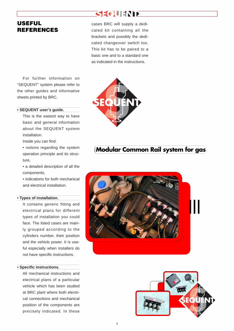
For further information on
“SEQUENT” system please refer to
the other guides and informative
sheets printed by BRC.
• SEQUENT user ’s guide.
This is the easiest way to have
basic and general information
about the SEQUENT system
installation.
Inside you can find:
• notions regarding the system
operation principle and its struc-
ture,
• a detailed description of all the
components,
• indications for both mechanical
and electrical installation.
• Types of installation.
It contains generic fitting and
electrical plans for different
types of installation you could
face. The listed cases are main-
ly grouped according to the
cylinders number, their position
and the vehicle power. It is use-
ful especially when installers do
not have specific instructions.
• Specific instructions.
All mechanical instructions and
electrical plans of a particular
vehicle which has been studied
at BRC plant where both electri-
cal connections and mechanical
position of the components are
precisely indicated. In these
cases BRC will supply a dedi-
cated kit containing all the
brackets and possibly the dedi-
cated changeover switch too.
This kit has to be paired to a
basic one and to a standard one
as indicated in the instructions.
6
USEFULREFERENCES
Modular Common Rail system for gas

Briefly all you need to “talk” with
the SEQUENT ECU is:
1. Portable PC
2. SEQUENT interface cable
(code DE512114)
3. PC SEQUENT Software on
CDROM
4. SEQUENT hardware key
Except for the PC which could
be ordered to BRC, all the other
components are contained inside
the kit “Software for SEQUENT”
code 90AV99002033.
In the picture 1.1 you will see
the SEQUENT interface cable while
in pictures 1.2A and 1.2B there is
the hardware key suitable for paral-
lel door in the first one and for USB
door in the second. The hardware
key for SEQUENT is easily recog-
nisable for the word SEQUENT or
SF hot pressed on one side; others
hardware keys even if suitable for
other BRC systems will not work.
In the next paragraphs a short
description with all characteristics
of what above.
1.1 THE PERSONALCOMPUTER
The SEQUENT software can be
used on PC with the following oper-
ating systems: Windows® 95 (only
starting from 4.00950b version),
Windows® 98, Windows® 2000,
Windows® ME e Windows® XP.
The required Hardware charac-
teristics are the following:
• Minimum Hardware characteris -
tics:
• Microprocessor: Pentium 133
• Memory RAM :16 MB
• Hard Disk: 1 GB
• 800X600 screen
• 1 serial door
• Suggested Hardware character -
istics:
• Microprocessor: Pentium II 350
• Memory RAM :64 MB
• Hard Disk: 1 GB
• 800X600 screen
• 1 serial door
7
1. WHAT DO YOUNEED TO START?
Pic. 1.1 -SEQUENT interfacecable
Pic. 1.2.A -Hardware key forparallel door
Pic. 1.2.B -Hardware Key forUSB door

For this purpose and on
demand BRC could supply portable
PC containing the updated software
whose functionality has been
already tested.
1.2 THE INTERFACECABLE FOR SEQUENTINSTALLA TIONS
This cable contains an electron-
ic circuit able to translate the ECU
signals corresponding to the motor-
car standard ISO 9141 and ISO
15031 into ones suitable for the PC
that is according the standard of
RS232 serial communication. The
cable is not compatible with the
other ones used for BRC sys -
tems, such as FLYING INJEC-
TION, JUST and JUST HEAVY.
It could be ordered to BRC with
the code DE512114.
1.3 SOFTWARE ANDHARDWARE KEY
The software is contained in the
CDROM supplied in the kit code
90AV99002033 “Software for
SEQUENT”
The CDROM also contains all
updating for the ECU programming
and these are anyway available in
the most updating version on inter-
net BRC site at the following
address: http:// www .brc.it.
8

The installation could be carried
out either through CDROM or
diskettes downloaded from internet
at http://www.brc.it.
In the same way it is possible to
update the PC software and all
ECU programming files (software,
loader, maps and adjustments)
either through CDROM or diskettes
downloaded from Internet.
Besides SEQUENT program
which allows to control and pro-
gram the ECU, in order to program
an ECU it is necessary to transfer
on the ECU itself the following files:
• The program making the ECU
operate.
• The loader, to go from an
already existing program to a
new one.
• The files containing the maps
of the developed vehicles (the
ones with name type AAP).
• The files containing the setting
of the developed vehicles (the
ones with name type FSF).
Let’s start from the beginning
and try to carry out the installation.
Let’s examine both programming
cases: with CDROM and with
diskettes.
2.1 “SEQUENT” SOFT -WARE INSTALLA TION ONPC WITH CDROM
As well as getting the portable
PC and the CDROM for the instal-
lation, to load “SEQUENT” software
you will have to follow these steps:
1. Switch the computer on and
wait for its starting
2. Introduce the CDROM.
3. Wait for the automatic starting
of the installation program (if it does
not occur please refer to what indi-
cated in the note regarding this pro-
cedure).
4. In the screen showed in pic-
ture 2.1 click on SEQUENT icon.
5. In the screen showed in pic-
ture 2.2 click on SEQUENT icon if
you are installing the program for
the first time; in case not click on
UPDATE SEQUENT icon to update
the software.
6. This procedure will lead you
through all installation steps. At
each question answer “Next” or
affirmatively.
7. If the installation indicates to
choose the destination, keep the
original one and click “Next”.
8. At this point the program
9
2. SOFTWAREINSTALLATION ANDHARDWARE KEYUSE
Pic. 2.1 - First installation screen
Pic. 2.2 - Second installation screen

installation starts (Picture 2.3); wait
till the sliding bar reach 100%.
9. When the screen displays
“InstallSchieldWizard Complete”
(Picture 2.4) click on Finish.
10. at this point the computer
could ask to close and start
Windows® again: answer Yes.
NOTE: the automatic starting
of SEQUENT program instal-
lation depends on the PC setting. In
case the installation does not auto-
matically begin, start the “Setup”
program contained in the main
CDROM fi le (Click on Start >
Execute, write “D:\Setup.exe” and
click on OK. “D” represents
CDROM; if there is another letter
you have to insert the correct one
in the computer.
2.2 SEQUENT” SOFTWAREINSTALLA TION ON PCWITH DISKETTES
If you prefer to carry out the
installation by using diskettes, you
will have to follow these steps:
1. Switch the computer on and
wait for its starting.
2. Introduce the first diskette for
SEQUENT software installation.
3. Start the “Setup” programme
(Click on Start > Execute, write
“A:\Setup.exe” and click on OK).
4. The installation program will
lead the user during the whole pro-
cedure.
5. To each question answer
“Next” or affirmatively.
6. If the installation indicates to
choose the destination, keep the
original one and continue clicking
on “Next” key.
7. At this point the program
installation starts (Picture 2.3); wait
till the sliding bar reach 100%.
8. When the screen displays
“InstallSchieldWizard Complete”
(Picture 2.4) click on Finish.
9. At this point the computer
could ask to close and start
Windows® again: answer Yes.
10. Insert the Hardware Key in
the printing plug (or in the parallel
one) which could be usually placed
backwards or, in the new PC ver-
sions insert the USB key in its plug.
11. Start the program (click on
Start > Programs > Sequent).
The new program is now able to
operate but it is necessary to down-
load the available maps and all the
files for the ECUs programming. All
above is contained in the site
www.brc.it or through diskettes and
CDROM.
10
Pic. 2.3 - Installation with sliding bar
Pic. 2.4 - Installation with Finish key

3.1 OPENING PAGEDESCRIPTION
After having correctly carried out
the installation and if the Hardware
Key has been introduced in the
printer door or USB one, it is possi-
ble to start and use SEQUENT pro-
gram. To start cl ick twice
SEQUENT icon on the PC screen
or point the low left angle of the
screen with the mouse choosing
”Start” > Programs > SEQUENT.
BE CAREFUL!: for a correct
visualisation of the program
pages, hide the Windows® “instru-
ments bar” (see picture 3.1). To do
that place the mouse pointer on the
bar where there are not icons of
opening programs, click on the right
key, choose “Properties” and finally
select the options “Always fore-
ground” and “Automatically hide” as
indicated in picture 3.1.
During the first start (pict. 3.2)
SEQUENT program is written in
English. To change language click
on UTILITY.
In the new menu click on
“CHANGE LANGUAGE”; select the
language you prefer and click on
CHOOSE (pict. 3.3).
A window with the writ ing
“WARNING” will advice the user he
is changing the language. Click on
OK and go out the program with
EXIT.
11
3. STARTING OFTHE PROGRAM ANDITS STRUCTURE
Pic. 3.1 - Hide Windows® instruments bar
Fig. 3.3 - First start – language selection
Fig. 3.2 - First start – language change

Starting the program again it will
be displayed in the new selected
language.
In describing this guide we obvi-
ously choose English one.
When starting again the window
of the program will be as shown in
picture 3.4.
The big icon with SEQUENT
symbol is easily recognisable;
when the mouse pointer is on the
icon its shape will change into a
question mark while clicking on the
left key you open a window with
some information on the installed
software as indicated in picture 3.5.
The software version contained
in the PC can be read down on the
right.
At the bottom the screen has 4
keys called “main keys” on which
we have 4 files; PROGRAMMING,
SETTING UP, DIAGNOSTIC and
UTILITY.
Their use will be explained later.
Over these files there is another
key with the word “EXIT”. By click-
ing on this one you quit the pro-
gram; if you do not modify or if you
save all changes, the program will
immediately close. Otherwise, if
changes and operations have not
been already saved or memorised
on the ECU, the program will ask
the user if he wants to save them or
not.
BE CAREFUL!: by answering
not, all changes will be lost
and it will be not possible to get
them back.
At the bottom of the screen
there are two narrow and long files
covering all the screen width. The
left one displays the current com-
munication condition (Fastening,
Communication, OK, etc.) while the
right one displays possible commu-
nication errors as, for example,
when the ECU programming is
stopped or other events occur.
3.2 MAIN KEYS
As already stated, the main
keys are 4 and are located at the
bottom of the screen.
All the files are closed (see pic-
ture 3.1). Each key has a writing
under the file drawing and from left
to right we have:
• PROGRAMMING
• SETTING UP
• DIAGNOSTIC
• UTILITY
Please note the underlined let-
ter.
The basic concept to keep in
mind to use this program is that
each main key corresponds to a
12
Pic. 3.4: SEQUENT opening page
Pic. 3.5: SEQUENT opening page after clicking on the icon

main function. To better understand
this philosophy you can imagine
each main key is a big drawer con-
taining all the necessary equipment
to develop an operation. When you
decide to perform it, open the draw-
er (or better cl ick on the key),
choose the equipment and carry
out the desired operation
For the ECU programming refer
to “PROGRAMMING” key, for the
setting up of an already pro-
grammed ECU choose “SETTING
UP”, to verify possible installation
errors or to test the actuators
choose “DIAGNOSTIC” and finally
to select some program options
(i.e. language, communication
parameters, etc) open the “UTILI-
TY” drawer.
By clicking on each key, the file
will open and you will see the con-
tents of the icon coming out. At the
same time on the left side of the
screen some keys appear, each
one with a specific task: these are
the before keys mentioned.
Each main key can be selected
by clicking the mouse or keeping
the ALT key and contemporarily the
underlined letter corresponding to
the key pushed (i.e. ALT+P for
PROGRAMMING, ALT+G for SET-
TING UP, etc.).
It is possible to select the key by
using the keyboard arrows up and
down: the red key is the selected
one.
By pushing the enter key on the
keyboard, you obtain the same
effect of clicking on the red key
with the mouse.
In the next paragraph there is a
short description of main keys.
Please refer to next chapter for the
detailed description including com-
plete procedures to use for each
single function.
3.2.1 “PROGRAMMING” KEY
This key allows to program the
ECU whether if i t is virgin or
already programmed. It is possible
to carry out both of them through
recorded files or files supplied by
BRC (choosing the key “FROM
RECORDS” ) and the self-map
(choosing the key “AIDED PER -
SONALISED” ). These two keys
appear on the left of the screen
when selecting the main key “PRO-
GRAMMING”.
3.2.2 “SETTING UP” KEY
It contains all the necessary
functions to modify maps, adjust-
ments, changeover parameters and
everything could effect SEQUENT
installation operations. By using the
SETTING UP instruments it is pos-
sible to revise every phase of the
aided procedure separately from
the others, to change the parame-
ters of petrol to gas change-over,
correct the self adapting maps, etc.
3.2.3 “DIAGNOSTIC” KEY
It allows to see the values in
order to understand if there are
possible problems or installation
mistakes, to verify the type of soft-
ware, loader and maps unloaded in
the ECU, to test the correct opera-
tion of actuators, injectors, sole-
noidvalves, relays, etc.
3.2.4 “UTILITY” KEY
It groups all the general utility
instruments not included in the pre-
vious categories. These allow to
effect some useful operations to
update the program or to modify
some aspects: you can change lan-
guage, communication parameters
with the ECU, display electrical
plans, extract the map and the set-
tings from the ECU and save them
on the PC, manage the files con-
taining already known vehicles
maps, create diskettes to transfer
the maps to another PC, update all
data on the PC.
13

4.1 PROGRAMMING FILESTYPE
The FLY SF ECU programming
procedure is based on the down-
load of three different types of
files:
1. S19 File
2. FSF File
3. AAP File
4.1.1 S19 FILE
The files with S19 extension
contain the algorithms and the
strategies used by SEQUENT sys-
tem. Each time you effect a new
programming of the ECU it is
advisable to update the S19 soft-
ware with the last version available
in the PC. Obviously the PC has to
be updated too. This allows to
have all the developed functions
and strategies available.
To better clarify the function of
S19 files, we could say that it cal-
culates the exact gas flow to sup-
ply the engine with and pilot the
injectors by analysing the vehicle
specific parameters (FSF file), the
map (AAP file) and all data coming
from the different sensors.
4.1.2 FILE FSF
The FSF file contains the spe-
cific data of the converted vehicle.
For example the type of installa-
tion (LPG or CNG), the engine
type (vacuum or LPG turbo), all
calibration parameters of the sig-
nals coming from the acquired
sensors, the change-over parame-
ters, the possible parameters for
tip-in strategies and the advance
setting up ones.
4.1.3 AAP FILE
The AAP file contains the vehi-
cle map. In particular the petrol
reference map, the gas one and
the map concerning cells condi-
tion. Cells condition map is useful
to identify the type of vehicle oper-
ation in the different operating
area, identified by MAP engine
revolution couples. These cells
could be Open-Loop or Closed-
Loop type.
4.2 ECU PROGRAMMING
In case you need to program an
ECU, it is necessary to select the
Programming key on the main
14
Lambda oxygensensor calibration
(step 5)
FSF file recording(step 6)
Self-mapping(step 7)
Equipment typeselection(step 1)
Aided personalizedprocedure start
Equipment andinjectors calibration
(step 2)
R.P.M. calibration(step 3)
T.P.S. calibration(step 4)
Aided personalizedprocedure end
(step 8)
LPG CNG
Lambda oxygensensor calibration
(step 6)
FSF file recording(step 7)
Self-mapping(step 8)
R.P.M. calibration(step 4)
T.P.S. calibration(step 5)
Aided personalizedprocedure end
(step 9)
Equipment typeselection
(step 1)
Equipment andinjectors calibration
(step 2)
Temperature sensorcalibration
(step 3)
Aided personalizedprocedure start
4. PROGRAMMING
Pic. 4.1: Guided personalised procedure steps

screen. There are two types of
programming available:
• Aided Personalised
• From records
4.2.1 AIDED PERSONALISED
PROGRAMMING
This type of programming has
to be carried out when you wish to
convert a new vehicle whose map
is not available. In this case start
the configuration of the person-
alised parameters and then the
real self-maping. The aided proce-
dure consists of 8 steps for LPG
and 9 for CNG as indicated in pic-
ture 4.1.
To enter this procedure, select
the Programming key at the bot-
tom of the screen and then the
Aided Personalised one, on the
left. The technician will be guided
step by step through all the differ-
ent phases of the procedure by a
red capital writing in the centre of
the screen. It is possible to go
through this procedure taking one
or more steps backwards or FOR-
WARD, by using the PREVIOUS
or NEXT keys at the bottom of the
screen (see picture 4.4b) or by
using PgUp and PgDwn keys on
the keyboard.
To correctly effect this proce-
dure, respect the conditions indi-
cated at the top of the screen (see
picture 4.2) displaying each step
the correct condition of:
• Engine (on or off).
• Ignition key (connected or
not).
• The changeover switch (gas
or petrol position).
• The vehicle (stopped or run-
ning).
Be careful: with the aided cali-
bration procedure all the parame-
ters on the ECU will be lost.
Hereunder the explanation of
the Personalised Aided Procedure
steps.
4.2.1.1 Type of installation
As shown in picture 4.3 this is
the first step and allows to select
the type of equipment installed in
the vehicle: LPG or CNG.
In case of a usual LPG or CNG
installation, after selecting the cell,
digit ENTER. Automatically the
ECU will receive the software and
a standard map to calibrate the
vehicle.
After sending the data the pro-
gram will ask to disconnect and
connect the ignition key again. At
the end the ECU contents will be
read and the program wil l go
directly to the next step without
further intervention of the techni-
cian.
15
Pic. 4.2 - Conditions at the top of the screen
Pic. 4.3 - Aided Procedure – type of installation

NOTE:
When entering this screen,
before doing any operation, the
PC program veri f ies the ECU
loader version and compares it
with the last downloaded one. If
the ECU loader is not updated, a
message will ask to do that (see
picture 4.3); in this case it is not
possible to continue the aided pro-
cedure until the ECU contains the
updated version (see paragraph
4.2.2 for procedure).
In particular cases indicated by
BRC, it could be necessary to
download a different software
by using “ADVANCED” key.
Clicking on it the following pos-
sibilities will appear:
• Default: it corresponds to the
software normally supplied by
BRC. Without a special authori-
sation given by BRC techni-
cians it will be possible to use
only standard software.
• Custom: it corresponds to
particular software used for
test ing and development.
These ones have to be used
only if indicate by BRC techni-
cians. After choosing this
option, select the software and
click OK in the window for the
software selection (see picture
4.4).
4.2.1.2 Installation and injectors
Calibration
This is the second step both for
LPG and CNG. It needs to specify
further information about the
installed equipment. Particularly it
allows to indicate if it is a vacuum
or a LPG turbo installation. As indi-
cated in picture 4.4b, in the section
where you can choose between
the above options there is the indi-
cation of the choice between LPG
or CNG confirmed in the previous
step (for technician convenience)
but no possibility to change it (the
writing is grey) To change you
have to cl ick on Previous and
repeat the procedure explained at
step 1. In this screen you can
select the installation characteris-
tics too:
• Injector type: indicates the
installed type of gas injector
choosing among the available
ones;
• N. of Genius: indicates how
many genius reducers have
been installed. Mostly it is one
so that this is the set value; it is
necessary to modify it only if
you have two;
• N. of P1 Sensors: indicates
how many P1 pressure sensors
have been installed. The set
value is one. Modify it if you
16
Pic. 4.3a - Aided Procedure – type of installation – not updated loader
Pic. 4.4 - Aided Procedure – type of installation clicking on “OTHER”
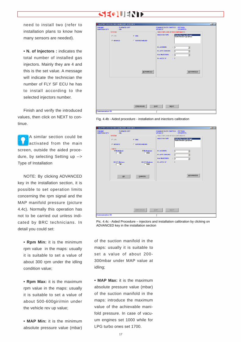
need to install two (refer to
installation plans to know how
many sensors are needed).
• N. of Injectors : indicates the
total number of installed gas
injectors. Mainly they are 4 and
this is the set value. A message
will indicate the technician the
number of FLY SF ECU he has
to instal l according to the
selected injectors number.
Finish and verify the introduced
values, then click on NEXT to con-
tinue.
A similar section could be
act ivated from the main
screen, outside the aided proce-
dure, by selecting Setting up -->
Type of Installation
NOTE: By clicking ADVANCED
key in the installation section, it is
possible to set operation limits
concerning the rpm signal and the
MAP manifold pressure (picture
4.4c). Normally this operation has
not to be carried out unless indi-
cated by BRC technicians. In
detail you could set:
• Rpm Min: it is the minimum
rpm value in the maps: usually
it is suitable to set a value of
about 300 rpm under the idling
condition value;
• Rpm Max: it is the maximum
rpm value in the maps: usually
it is suitable to set a value of
about 500-600giri/min under
the vehicle rev up value;
• MAP Min: it is the minimum
absolute pressure value (mbar)
of the suction manifold in the
maps: usually it is suitable to
set a value of about 200-
300mbar under MAP value at
idling;
• MAP Max: it is the maximum
absolute pressure value (mbar)
of the suction manifold in the
maps: introduce the maximum
value of the achievable mani-
fold pressure. In case of vacu-
um engines set 1000 while for
LPG turbo ones set 1700.
17
Fig. 4.4b - Aided procedure - installation and iniectiors calibration
Pic. 4.4c - Aided Procedure – injectors and installation calibration by clicking onADVANCED key in the installation section
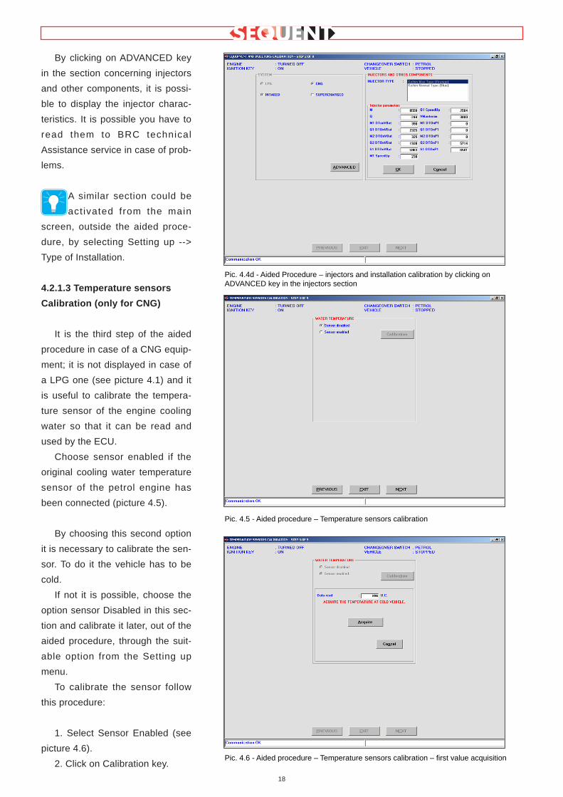
By clicking on ADVANCED key
in the section concerning injectors
and other components, it is possi-
ble to display the injector charac-
teristics. It is possible you have to
read them to BRC technical
Assistance service in case of prob-
lems.
A similar section could be
act ivated from the main
screen, outside the aided proce-
dure, by selecting Setting up -->
Type of Installation.
4.2.1.3 Temperature sensors
Calibration (only for CNG)
It is the third step of the aided
procedure in case of a CNG equip-
ment; it is not displayed in case of
a LPG one (see picture 4.1) and it
is useful to calibrate the tempera-
ture sensor of the engine cooling
water so that it can be read and
used by the ECU.
Choose sensor enabled if the
original cooling water temperature
sensor of the petrol engine has
been connected (picture 4.5).
By choosing this second option
it is necessary to calibrate the sen-
sor. To do it the vehicle has to be
cold.
If not it is possible, choose the
option sensor Disabled in this sec-
tion and calibrate it later, out of the
aided procedure, through the suit-
able option from the Setting up
menu.
To calibrate the sensor follow
this procedure:
1. Select Sensor Enabled (see
picture 4.6).
2. Click on Calibration key.
18
Pic. 4.4d - Aided Procedure – injectors and installation calibration by clicking onADVANCED key in the injectors section
Pic. 4.5 - Aided procedure – Temperature sensors calibration
Pic. 4.6 - Aided procedure – Temperature sensors calibration – first value acquisition

3. Click on the Acquire key to
memorise the temperature when
the vehicle is cold. This operation
will take a few seconds.
Note: This acquisition has to
be carried out when the tem-
perature of the engine water is
enough cold. For example at 40°C.
4. Introduce the Cold Vehicle T
value corresponding to the
acquired engine water temperature
in °C (i.e. 40 °C) as indicated in
picture 4.7 and confirm with OK.
5. Switch the engine on and
wait till the temperature is enough
high and acquire the temperature
with warm vehicle cl icking on
Acquire key (picture 4.8). For
example you can wait for the fan
operation which occurs around
100 °C.
6. Introduce the warm Vehicle T
value corresponding to the
acquired engine water temperature
in °C as indicated in picture 4.9
(i.e. 100 °C if you wait for the van
operation to acquire the tempera-
ture with warm vehicle).
After finishing this calibration,
go on with Next key; if it has been
modified you will be asked to con-
firm the introduced values. Usually
the answer is positive and in this
case all data will be memorised
(the previous ones will be deleted)
and you will approach the next
step.
With a negative answer old
data wi l l be kept and you wi l l
approach the next step. By clicking
on Cancel you will stay in the cur-
rent page and you will not continue
the procedure.
19
Pic. 4.7 - Aided Procedure – temperature sensors calibration – first value acquisition
Pic. 4.8 - Aided Procedure – temperature sensors calibration – second value acquisition
Pic. 4.9 - Aided Procedure – temperature sensors calibration – second value acquisition

4.2.1.4 Rpm calibration
This if the third step in case of
LPG installation and the forth one
in case of a CNG one (see picture
4.1)
Entering the rpm calibration
sect ion, in the Set rpm signal
menu, the rpm signal type will be
displayed as it is read according to
the current ECU definition (see
picture 4.10).
If rpm value is not correctly
read, it is necessary to carry out
the automatic calibration proce-
dure by using Change Calibration
key.
The program will ask to keep
the engine at idle while running
with petrol (see picture 4.11).
You just have to confirm with
OK to automatically take the rpm
signal type.
At this point, if the rpm is one of
the system set ones, its name will
be displayed in the rpm signal type
taken by the automatic procedure
menu. In case the used rpm signal
is not in the list, the message ”No
determined setting” so appears
that you will have to manually set
the parameters through the indica-
t ions appearing by cl icking on
ADVANCED key. (For this opera-
tion please contact BRC techni-
cians).
20
Pic. 4.10 - Aided Procedure – rpm calibration
Pic. 4.11 - Aided Procedure – rpm by using Change Calibration key
Pic. 4.12 - Aided Procedure – rpm calibration by clicking on ADVANCED key

If the automatic procedure took
a known rpm signal (it usually hap-
pens) you just need to click on
Confirm to continue (picture 4.13).
At this point it is better to verify
rpm are correctly read and this
control could be made, for exam-
ple, at idle and at 3000 rpm.
If everything is correct, click on
NEXT, and positively answer to the
confirmation question; then contin-
ue the Aided Procedure.
4.2.1.5 TPS Calibration
This is the fourth step for LPG
installations and the fifth one for
CNG (see picture 4.1).
Entering the screen for the TPS
calibration, the procedure auto-
matically begins (picture 4.15).
First of all it is necessary to verify
the operation conditions (the ones
written in blue at the top of the
screen). The vehicle has to be
stopped with the engine running
on petrol.
At the beginning the engine has
to be on with the accelerator com-
pletely released. After the program
will indicate to execute three com-
plete and uniform accelerations.
It the TPS calibration has not
been correctly executed it is possi-
ble to modify i t by cl icking on
Change Calibration key as indicat-
ed in picture 4.15.
At the end, click on Next, con-
firm the acquisitions and continue
the Aided Procedure.
21
Pic. 4.13 - Aided Procedure Guided Procedure – automatic rpm calibration
Pic. 4.14 - Aided Procedure – TPS calibration
Pic. 4.15 - Aided Procedure – TPS calibration ended

4.2.1.6 Oxygen Sensor
Calibration
It is the fifth step for LPG instal-
lation and the sixth one for CNG
(see picture 4.1).
The Oxygen sensor calibration
is very important for this system as
this signal is used to speed up and
optimize the self-learning strategy.
It is important to know some
oxygen sensor characteristics such
as if it is a “CURRENT” or a “VOLT-
AGE” one (ordinary oxygen sen-
sor), if it is “straight” or “reverse”.
Let’s explain the meaning:
• Straight Oxygen sensor: the
high tension level corresponds
to a “rich” situation of the mix-
ture and, on the contrary, the
low tension level to a “lean” situ-
ation of the mixture.
• Reverse Oxygen sensor: the
opposite of Straight one.
Note: usually if the oxygen sen-
sor is a current type, it is a reverse
one, too.
Identification method: with a
sharp acceleration and standing
still, execute a cut- off (released
condition where there is no injec-
tion); if the oxygen sensor is low it
is a Straight one otherwise it is a
Reverse one.
The Current oxygen sensor is
recognisable for its extremely differ-
ent behaviour compared to the
Voltage oxygen sensor one.
During stationary conditions (at
idle) when the vehicle is in control,
a voltage oxygen sensor continu-
ously varies between minimum and
maximum tension value while a
current one will keep practically the
same value.
Only executing sharp tip-in or
during an open-loop phase, this
value notably changes. Please
remember current oxygen sensors
are mainly used by some car man-
ufacturers (i.e. Volkswagen) and
the mostly have more that 4 cables.
Once these parameters are set
and verified, continue the oxygen
sensor signal calibration. With the
engine at about 3000 rpm wait till
oxygen sensor start to check (see
picture 4.16) them click on Next
(not the one at the bottom of the
screen or you will directly go to the
next step) and start the automatic
calibration procedure. Keep the
engine at 3000 rpm and wait till the
program acquires the oxygen sen-
sor working range (see picture
4.17).
The calibration could be repeat-
ed, in case of mistakes, by clicking
Calibration, executing again all the
above listed operations.
At the end click on Next again
and confirm the acquired data.
22
Pic. 4.16 - Aided Procedure – Oxygen sensor calibration
Pic. 4.17 - Aided Procedure – Oxygen sensor calibration clicking on Forward

4.2.1.7 FSF file Saving
This is the sixth step for LPG
installation and the seventh one
for CNG (see picture 4.1).
This section requires to select
the destination file where the set-
tings dotained up to now have to
be saved. Under the main f i le
USER_MAPS select the type of
installation (LPG or CNG) and fill
the below cel ls in, indicat ing
Trademark, Model, ECU, File (pic-
ture 4.18) in the most detailed
way.
For example, in case of a vehi-
cle with the following characteris-
tics:
Installation: CNG
Trademark: Ford
Model: Mondeo 1800i 16v
(BWY)
ECU: Visteon LBO-110 Levanta
File: AZ982BP
we will obtain what indicated in
picture 4.18:
Note: in choosing the file
name you can use whatever
you prefer. A good suggestion is to
use a name which makes you
identify the vehicle where the file
has been downloaded (for exam-
ple the plate number).
With the engine off and the
ignition key on, it is possible to
click on Save that means all cali-
brations will be saved on the PC
and downloaded in the ECU.
Clicking Exit, without saving, all
executed calibrations will be lost.
Choosing to continue, after the
ECU programming, you will have
to switch the dashboard off and
then on and after click on Next: at
this point you enter the self-map-
ping section.
4.2.1.8 Self-mapping
SEQUENT system bases its
operation on the maps contained
in the ECU which allow to translate
the petrol injectors signals into
orders for the gas injectors. These
are different according to the vehi-
cle. The aim of the self-mapping is
to obtain the translation maps
through simple acquisitions (on
road) of the vehicle operating con-
dit ions, immediately after the
installation.
There is also a self-learning
function able to correct possible
map error following the slow varia-
tions due to the system ageing, a
calibration loss or a slow deteriora-
tion of gas and petrol components.
To make the self-mapping and
the self-learning possible, it is nec-
essary to acquire and store two
maps, one for the petrol operation
and the other for the gas one. The
translat ion from petrol to gas
comes from the union and compar-
ison of these two information car-
ried out by the ECU.
The vehicle map procedure fol-
lows the phases listed hereunder:
1.Petrol Self-mapping
2.Creation of the gas operation
rough map
3.Gas Self-mapping
4.Map and full load check.
4.2.1.8.1 PETROL MAP
In this phase, during petrol
operat ion, the instal ler has to
acquire different operation points,
related to rpm and manifold pres-
sure (MAP). The PC program will
obtain the complete map during
petrol operation by means of suit-
able extrapolation algorithms.
The map is based on a table
with 16 lines and 16 columns. On
each line there are 16 points with
constant rpm while the MAP (suc-
tion manifold pressure) increases
23
Pic. 4.18 -Aided Procedure – FSF file saving

moving to the right. On the con-
trary, in each column the MAP
value does not change while rpm
increase moving down.
Please keep in mind the MAP
value increases (on the same rpm)
according the throttle valve open-
ing to (that is pressing the acceler-
ator more); therefore during the
self-mapping we move to the right
on the map by accelerating, shift-
ing up and looking for hil l trial
courses.
To move down the cartography
you have to achieve very high
rpm, for example, increasing the
vehicle speed, shifting down, etc.
In this case, the white column on
the left of the screen, with values
from 300 to 6250, contains rpm
values concerning to each line of
the table. At the same time, the
high white line with values from
125 to 965 contains the MAP value
in mbar concerning each column
of the map. At the beginning the
cells of this table are red and the
inside value is zero “O”.
The cell where you are corre-
sponding to the current rpm and
MAP collected by the system is
enlarged during the acquisition
(see picture); at the same time
rpm and MAP values concerning
the centre of the cell are displayed
in blue on the border of the table
In the upper cells, indicated as
RPM and MAP, the vehicle real
values are displayed as shown in
picture 4.20. The displayed cell
keep to have value “0” till the oper-
ation points acquisition does not
begin. This acquisition starts as
soon as we achieve the optimal
conditions (reducer temperature,
engine on for enough t ime,
changeover switch in petrol posi-
tion, constant operation conditions,
etc) and the Start key (at the bot-
tom left) has been pushed. The
value “0” starts to increase as
shown in picture 4.20. The techni-
cian is informing again the map
phase begins through the mes-
sage Acquisition in progress (at
the bottom of the screen).
Going on with the description of
the screen shown in picture 4.20,
besides the first two cells at the
top left (RPM and MAP) we have
the following information;
• Petrol duty-cycle inj.: shows
the value picked up by the sys-
tem in that moment for the
petrol injectors Duty Cycle;
• Lambda 1: shows the oxygen
sensor electric value;
In the upper part of the screen
(picture 4.20) we have three files:
1.Petrol Map
2.First gas map
24
Pic. 4.19 - Aided Procedure – petrol self-mapping beginning
Pic. 4.20 - Aided Procedure – petrol self-mapping

3.Second gas map
Only the first file is selectable
and active when you start a new
map, while the other two are auto-
matically activated by the program
itself. Fit the end of petrol self-
mapping begins the gas one. All
these files can be selected and
activated by the user when he
decides to continue a previous
stopped self-mapping, where the
petrol map processing was carried
out. While some operation points
are acquired in the same cell, its
colour changes from red to yellow.
This indicates that operation point
has been acquired with few points
but it can be used by the extrapo-
lation algorithms which calculate
the complete map (see picture
4.21). Going on in acquiring oper-
ation points in the same cell, the
colour becomes green indicating
the acquired points are enough for
a good map. When the number
contained in the cell achieves the
maximum (for example 50), the
next acquired point wil l be not
memorised and used to develop
the final map; also the number in
the cell does not increase any-
more.
A good map could be obtained
by acquiring more cells as possi-
ble, avoiding to leave a big area of
the map without acquisition (red),
for example full load or high rpm,
etc.) The ideal situation is to obtain
a map with many green points for
all MAP and rpm values (i.e. see
picture 4.22).
The points acquisition can be
stopped anytime (for example if
traffic conditions are averse) click-
ing Stop at the bottom left (picture
4.21) and started again clicking
the same key (the wri t ing wi l l
change into Start – picture 4.22).
When the table contains
enough wel l distr ibuted green
and/or yellow cells, it is possible to
continue the interpolation of the
missed points (red) with the cre-
ation of the final petrol map. To do
that, stop the points acquisition
clicking Stop and then Compute at
the right bottom of the screen (pic-
ture 4.22). This operation begins, if
possible, the acquired data pro-
cessing, creats the petrol map, an
initial gas one and transfers every-
thing in the ECU. At this point the
procedure moves to the screen for
the first gas map.
4.2.1.8.2 GAS SELF-MAPPING
At the end of the petrol map
phase, you can start the gas one.
The gas self-mapping is divided in
two steps:
1.First gas map
25
Pic. 4.21 - Aided Procedure – petrol self-mapping with some points
Pic. 4.22 - Aided Procedure – complete petrol map
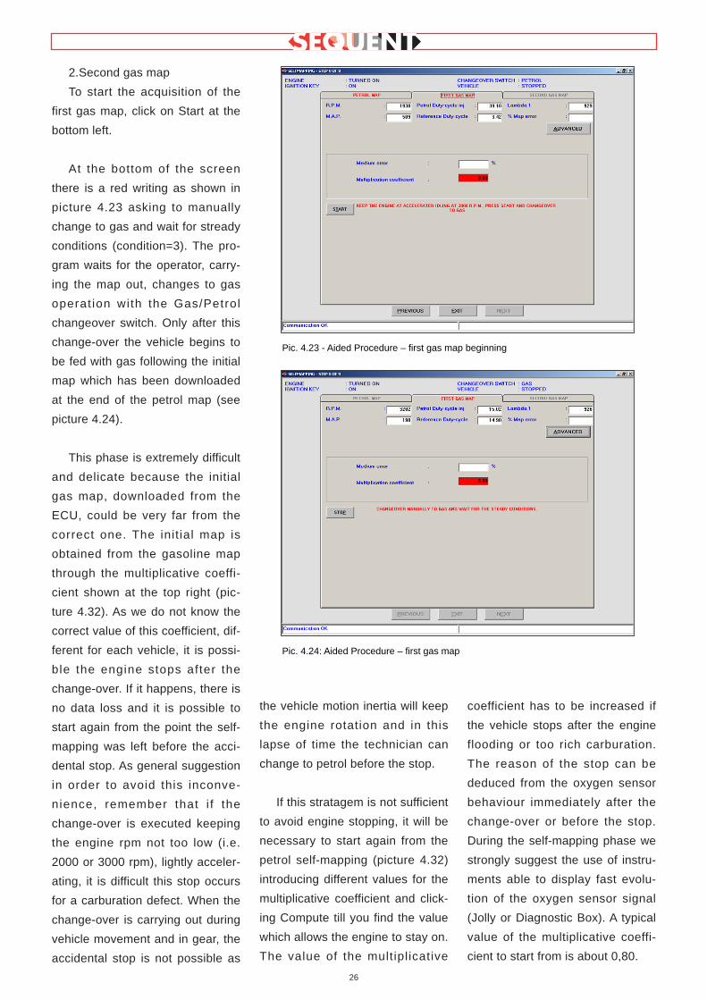
2.Second gas map
To start the acquisition of the
first gas map, click on Start at the
bottom left.
At the bottom of the screen
there is a red writing as shown in
picture 4.23 asking to manually
change to gas and wait for stready
conditions (condition=3). The pro-
gram waits for the operator, carry-
ing the map out, changes to gas
operat ion with the Gas/Petrol
changeover switch. Only after this
change-over the vehicle begins to
be fed with gas following the initial
map which has been downloaded
at the end of the petrol map (see
picture 4.24).
This phase is extremely difficult
and delicate because the initial
gas map, downloaded from the
ECU, could be very far from the
correct one. The init ial map is
obtained from the gasoline map
through the multiplicative coeffi-
cient shown at the top right (pic-
ture 4.32). As we do not know the
correct value of this coefficient, dif-
ferent for each vehicle, it is possi-
ble the engine stops after the
change-over. If it happens, there is
no data loss and it is possible to
start again from the point the self-
mapping was left before the acci-
dental stop. As general suggestion
in order to avoid this inconve-
nience, remember that i f the
change-over is executed keeping
the engine rpm not too low (i.e.
2000 or 3000 rpm), lightly acceler-
ating, it is difficult this stop occurs
for a carburation defect. When the
change-over is carrying out during
vehicle movement and in gear, the
accidental stop is not possible as
the vehicle motion inertia will keep
the engine rotation and in this
lapse of time the technician can
change to petrol before the stop.
If this stratagem is not sufficient
to avoid engine stopping, it will be
necessary to start again from the
petrol self-mapping (picture 4.32)
introducing different values for the
multiplicative coefficient and click-
ing Compute till you find the value
which allows the engine to stay on.
The value of the multiplicative
coefficient has to be increased if
the vehicle stops after the engine
flooding or too rich carburation.
The reason of the stop can be
deduced from the oxygen sensor
behaviour immediately after the
change-over or before the stop.
During the self-mapping phase we
strongly suggest the use of instru-
ments able to display fast evolu-
tion of the oxygen sensor signal
(Jolly or Diagnostic Box). A typical
value of the multiplicative coeffi-
cient to start from is about 0,80.
26
Pic. 4.23 - Aided Procedure – first gas map beginning
Pic. 4.24: Aided Procedure – first gas map

Achieving the stationary condi-
tions, the program begins to calcu-
late the best fuel quantity to supply
according to the engine operation
conditions. During this phase try to
keep the operat ion condit ions
more constant as possible (stand-
still accelerator and constant rpm).
The red writing of the screen dis-
appears and in the % Map Error
cell we have a numerical value
indicating the entity of the correc-
tion executed by the program to
achieve ideal carburation condi-
tions (see picture 4.25).
While the program achieves a
more precise correction, the map
error decreases till it is less than
the set maximum error (this latter
could be set through OTHER).
When it occurs, the multiplicative
coefficient cell changes from red to
green and the initial value changes
too (see picture 4.30 whose value
decreases from 0,80 to 0,79).
Wait for a few seconds to be
sure the new multiplicative coeffi-
cient value (0,79 in picture 4.26) is
fixed then click on Stop and down-
load the new map obtained from
the petrol one and the new multi-
plicative coefficient.
You will be asked to change to
petrol (condition = 2 or 1) so set
the changeover switch in the petrol
position to make the map down-
load in the ECU possible.
The other cells in this screen
have the following meaning:
• Petrol Duty-cycle inj.: shows
the duty cycle taken from the
petrol injectors (cut and emulat-
ed).
• Reference Duty-cycle:
shows the petrol duty cycle
value expected by the map in
that point.
• % Map error: shows the
medium shifting between the
petrol duty cycle and the refer-
ence one; it is positive if the
petrol inj. duty cycle is bigger
than the reference one that
usually means the gas map is
lean or the petrol map has too
low values.
• Lambda1: it has the same
meaning of the petrol self-map-
ping.
27
Pic. 4.25 - Aided Procedure – first gas map after change-over
Pic. 4.26 - Aided Procedure – complete first gas map
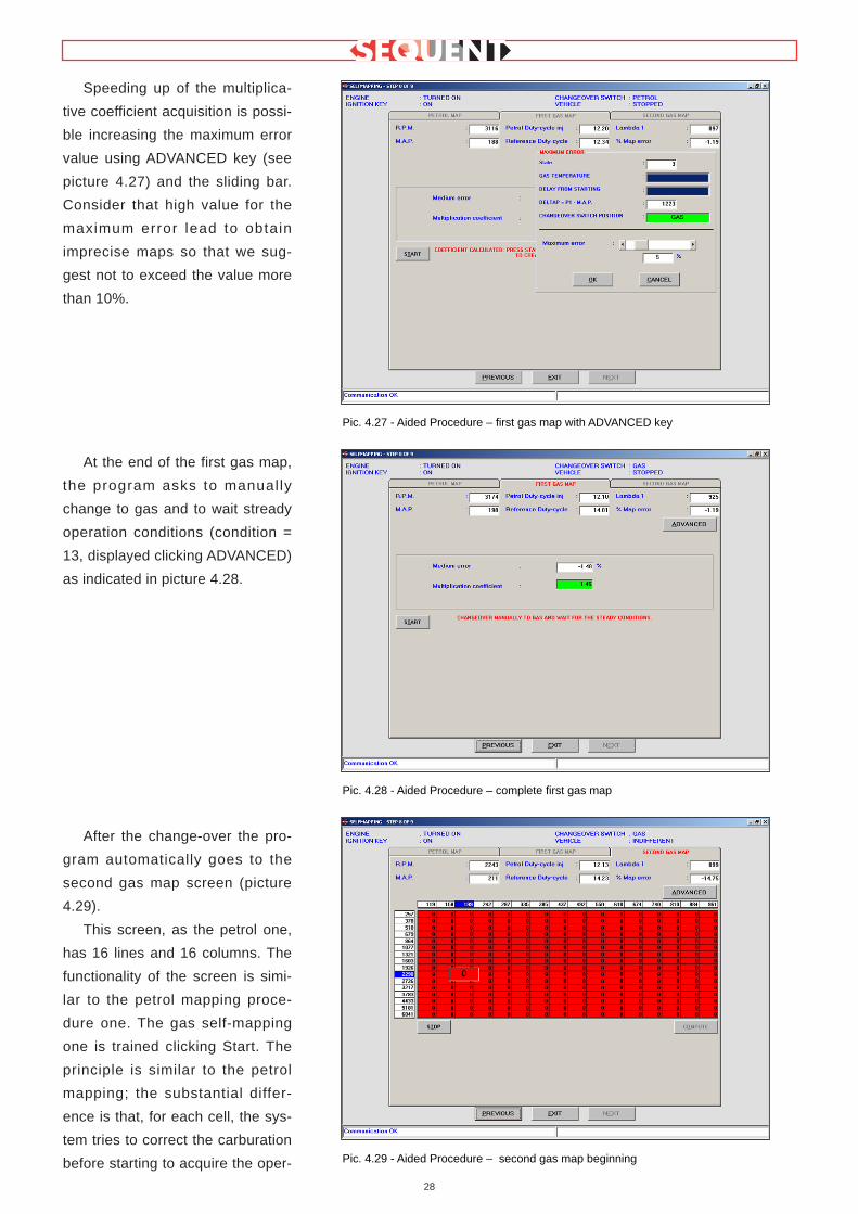
Speeding up of the multiplica-
tive coefficient acquisition is possi-
ble increasing the maximum error
value using ADVANCED key (see
picture 4.27) and the sliding bar.
Consider that high value for the
maximum error lead to obtain
imprecise maps so that we sug-
gest not to exceed the value more
than 10%.
At the end of the first gas map,
the program asks to manual ly
change to gas and to wait stready
operation conditions (condition =
13, displayed clicking ADVANCED)
as indicated in picture 4.28.
After the change-over the pro-
gram automatically goes to the
second gas map screen (picture
4.29).
This screen, as the petrol one,
has 16 lines and 16 columns. The
functionality of the screen is simi-
lar to the petrol mapping proce-
dure one. The gas self-mapping
one is trained clicking Start. The
principle is similar to the petrol
mapping; the substantial differ-
ence is that, for each cell, the sys-
tem tries to correct the carburation
before starting to acquire the oper-
28
Pic. 4.27 - Aided Procedure – first gas map with ADVANCED key
Pic. 4.28 - Aided Procedure – complete first gas map
Pic. 4.29 - Aided Procedure – second gas map beginning

ation points. These latter, repre-
sented by the cel ls, are not
acquired till the Map Error is not
less then the set Maximum Error
value (see picture 4.30).
The carburation centering is
made for each cel l and stops
whenever you go on contiguous
cells; moreover it waits maximum
error and waiting time limits are
respected . For these reasons this
procedure is slower than the petrol
one and requires the conditions to
be constant for a longer time.
At the beginning the map is
zero and all cells are red (picture
4.29). While you execute some
acquisitions the colour changes
from red to yellow and then to
green and, at the same time, the
inside number increases. The
acquisition criteria is the same of
the petrol mapping. In the picture
4.31 we show the example of a
complete map.
To end the gas map acquisition
just click Stop, at the bottom left.
Before executing the data pro-
cessing you have to manual ly
change to petrol operation by turn-
ing the petrol/gas changeover
switch.
If the change-over does not
occur it will be not possible to con-
tinue the data processing; this
condition will be anyway displayed
with an error message. After a cor-
rect change-over, click Compute to
start the gas missed points inter-
polation and the download of the
final map to the ECU.
Note:
• There are some reasons
why the petrol or gas self-
mapping could create errors and
not correctly finish. This could hap-
pen is, for example, the acquired
points are not enough or if the
acquisitions are not plausible. The
not operating conditions will be
indicated with an error message. if
all conditions have been correctly
verified, the initial gas map is cre-
ated from the petrol one.
• The first gas map is created
from the petrol one and the multi-
plicative coefficient displayed click-
ing ADVANCED (picture 4.32).
Usually the coefficient value is
0,80. If you can not continue the
gas map, for example because the
initial map is too lean and the vehi-
cle stops when changing to gas, it
is possible to return to this phase,
modify the multiplicative coefficient
(for example increasing it to obtain
29
Pic. 4.30 - Aided Procedure – second gas map with an acquired point
Pic. 4.31 - Aided Procedure – complete second gas map

a richer map) and then click on
Compute again.
• When clicking ADVANCED
the Condition value is displayed;
this indicates the changeover
switch position and the injected
fuel: during normal petrol opera-
tion, with the changeover switch in
petrol position, with a sufficient
reducer temperature, the car run-
ning for enough time and in not tip-
in conditions, the cell has value 1.
In all other cases the value is dif-
ferent and the acquisition is not
executed. The gas temperature
and the change-over are repre-
sented by two sliding bars (picture
4.32): if the bars are completely
blue, acquisition conditions have
been achieved, on the contrary we
have to wait the temperature or
the ignition time reaching.
• I f you prefer to execute a
more precise petrol or gas self-
mapping, you can check its relia-
bility before executing the next
steps. To check it, leave the self-
mapping procedure by entering the
Setting Up screen and then the
Self-learning one. The value indi-
cating the map centering is con-
tained in % Error cell, at the top
left, as shown in picture 4.33.
Acceptable error values have to be
±5%. If more than ±10% the map
has to be considered not very cen-
tred. By staying a long on a not
centred point, the ECU self-learn-
ing will centre it better so that the
percentage error decreases. It is
possible to obtain more precise
and centred petrol maps running
on petrol after the petrol self-map-
ping and before executing the gas
one.
30
Pic. 4.32 - Aided Procedure – petrol map clicking OTHER
Pic. 4.33 - Self-learning check

• Anytime it is possible to stop
an acquisition and start it again in
order to verify the centering or for
any other reason. For example,
after having executed part of the
petrol acquisition, that is before
downloading the map in the ECU,
it is possible to stop, switch the PC
off and start the work again later
recalling the name chosen at the
beginning of the map. The same
occurs if the petrol map has been
completed and downloaded in the
ECU. To start the work again, in
the main screen select Setting Up
and Self-mapping: you wil l be
asked to select the previously
saved vehicle file (picture 4.34).
By selecting the file, the map
screen will be opened by selecting
the file (picture 4.35).
From this section you can enter
and modify petrol and gas maps,
following the indications in para-
graph 5.7.
4.2.1.9 Parameters transfer to
the ECU
With this last section the new
vehicle signals and self-mapping
calibration procedure ends. You
will be asked to turn the ignition
key off and then on again (see pic-
ture 4.36).
To return to the main screen,
click on End.
31
Pic. 4.34 - To start a partial self-mapping again – file choice
Pic. 4.35 - To start a partial self-mapping again
Pic. 4.36 - Final screen with red message

4.2.2 PROGRAMMING
“F ROM RECORDS”
By selecting Programming >
From Records you enter the
screen for the FLY SF ECU pro-
gramming from records, that is you
will use files available or wich are
available supplied by BRC. To cor-
rectly program the ECU, verify the
operation conditions displayed at
the top of the screen. If they will be
not respect, it is not possible to
execute the programming and this
situation will be anyway displayed
by the installer program.
To execute the programming,
select the file you want to down-
load in the records (according to
the type of installation, trademark,
model and petrol ECU). If the vehi-
cle has been developed by BRC,
the f i les wi l l be contained in
BRC_MAPS, if it has been devel-
oped by the technician the files will
be in USER_MAPS.
In picture 4.37 we selected :
Map: developed by the user
(User_Maps)
Installation: CNG
Trademark: Ford
Model: Mondeo 1800i 16v
(BWY) 92kW EuroIV
ECU: Visteon LBO-110 Levanta
Once the vehicle ECU number
is chosen, select the files to be
downloaded. The example in the
picture shows, for the ECU type
there is only one FSF f i le
(AB567CA.FSF) and only one AAP
file (AB567CA.AAP).
To select the FSF file you have
to click twice on the file itself and
automatically a tick will be marked
near the Vehicle Parameters writ-
ing and the name of the selected
file will be displayed in the cell
below.
The selection of the software to
be downloaded (file .S19) is auto-
matically carried out when choos-
ing the Vehicle Parameters file (file
.FSF). To transfer it to the ECU it
is necessary the cel l near
Software writing is marked with a
tick. You can change the software
through ADVANCED, as indicated
in picture 4.38. Clicking it, a cell
containing the different available
software versions wi l l be dis-
played. We suggest to carry these
operations out only if advised by
BRC technicians or qualified per-
sonnel.
Click twice to select the .AAP
file and a tick will be automatically
marked near Mapping writing and
the name of the selected file will
be displayed in the below cell.
32
Pic. 4.37 - From records Programming
Pic. 4.38 - Programming from records – file S19 selection

The tick marks the files which
will be simultaneously downloaded
when continuing the ECU pro-
gramming clicking Program.
In Picture 4.39 all the three files
are simultaneously downloaded
(FSF, S19 e AAP).
At one time, it is possible to
make the following combinations:
• FSF
• AAP
• FSF + S19
• FSF + S19 + AAP
Sometimes it could be neces-
sary to update the loader on the
ECU. In this case the program
automatically informs the techni-
cian to do that when he chooses to
execute a guided personalised
programming of the ECU.
To update the loader, click on
LOADER UPDATING (see picture
4.39): the program will open a
page displaying a red writing with
all the indications, according to the
situat ion of the ECU. Cl icking
PROGRAM at the bottom of the
screen, the loader download
starts. At the end of this operation
a message will inform the opera-
tion has been correctly executed
and it is necessary to turn the igni-
tion key off and then on (picture
4.40).
NOTE:
While updating the ECU loader
you could face the following possi-
bilities:
1.The ECU contains a loader
version less than 106. In this case
the screen is the one of picture
4.40a and the writing in the centre
33
Pic. 4.39 - Programming from records – simultaneous selection of the three files
Pic. 4.40 - Correctly ended updating
Pic. 4.40a - ECU Loader updating if less than 106

informs the operation will be exe-
cuted in two steps: the first one
executes the loader programming
with 106 version (see picture
4.40b) and the second one will
download the most updated loader
available in the PC. At the end of
the first step you will be asked to
turn the ignition key off and then
on and click on OK (picture 4.40b)
At this point the second program-
ming starts and at the end a mes-
sage displaying it has been cor-
rectly executed appears (picture
4.40).
2.The ECU contains a loader
version higher or equal to 106, but
less than the last version con-
tained in the PC. in this case the
screen is the one of picture 4.40c
and the wri t ing in the centre
informs it is better to update the
ECU.
3.The ECU already contains
the last version. The screen is the
one displayed in picture 4.40d
where the writing in the centre
informs i t is not necessary to
update it.
4.The ECU has a loader ver-
sion more updated than the PC
one. This possibility occurs when
the PC has not been updated with
the last loader versions: in this
case we strongly suggest to
update the PC.
The screen is the one of picture
4.40e where the writing in the cen-
tre of the screen informs it is better
not to update the ECU as it will be
less updated than it is.
We suggest to carry this opera-
tion out only if advised by BRC
technicians or qualified personnel.
34
Pic. 4.40b - Loader updating – first step
Pic. 4.40c: ECU loader updating if higher than 106
Pic. 4.40d - ECU loader updating if it is the same of the PC one

BE CAREFUL!:
• If the loader programming
stops as soon as it starts you have
to turn the ignition key off and then
on, and try again.
• Trying to update the loaders
start ing from versions less or
equal to 105, the programming
could be not executed in spite of
the repeated attempts. In this case
follow the listed indications:
1. From the main page select
PROGRAMMING > FROM
RECORDS
2. Select a start map from
BRC_MAPS.
3.In the VEHICLE PARAME-
TERS window, select the FSF file
in order to mark a tick on the cell.
4.Click on PROGRAM at the
bottom right to start the FSF pro-
gramming.
5.When the sliding bar indicat-
ing the programming process
appears, stop the communication
by turning the ignition key off and
then on.
6.Try again to update the
loader.
35
Pig. 4.40e: ECU loader updating if the ECU is less than the PC one
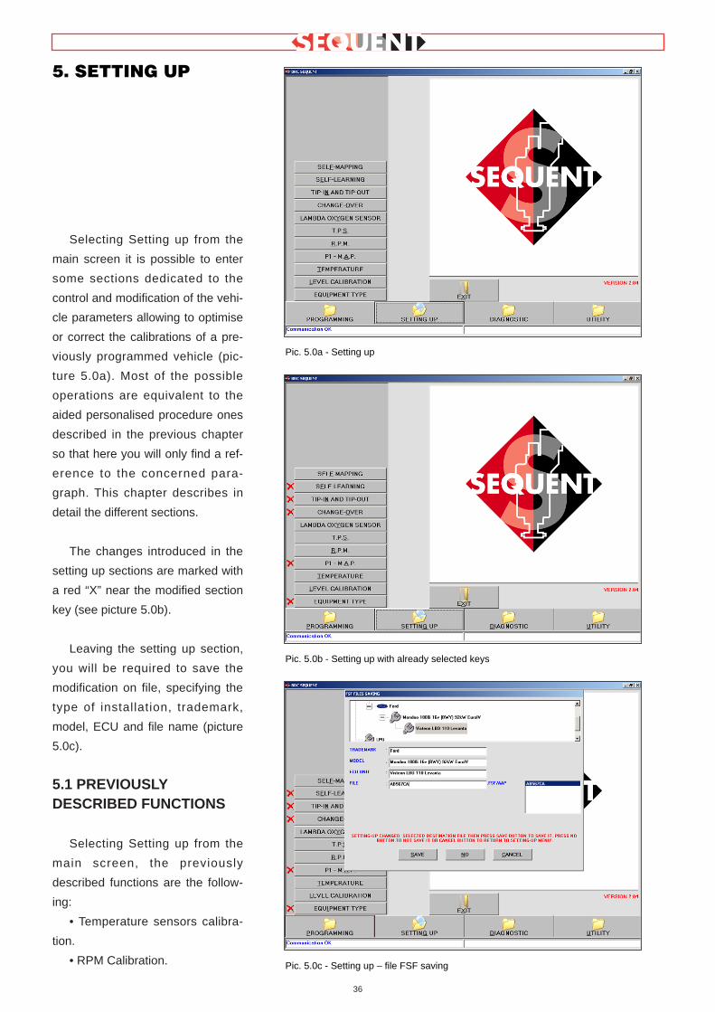
Selecting Setting up from the
main screen it is possible to enter
some sections dedicated to the
control and modification of the vehi-
cle parameters allowing to optimise
or correct the calibrations of a pre-
viously programmed vehicle (pic-
ture 5.0a). Most of the possible
operations are equivalent to the
aided personalised procedure ones
described in the previous chapter
so that here you will only find a ref-
erence to the concerned para-
graph. This chapter describes in
detail the different sections.
The changes introduced in the
setting up sections are marked with
a red “X” near the modified section
key (see picture 5.0b).
Leaving the setting up section,
you will be required to save the
modification on file, specifying the
type of installation, trademark,
model, ECU and file name (picture
5.0c).
5.1 PREVIOUSLYDESCRIBED FUNCTIONS
Selecting Setting up from the
main screen, the previously
described functions are the follow-
ing:
• Temperature sensors calibra-
tion.
• RPM Calibration.
36
5. SETTING UP
Pic. 5.0a - Setting up
Pic. 5.0b - Setting up with already selected keys
Pic. 5.0c - Setting up – file FSF saving

• TPS Calibration.
• Oxygen sensor Calibration.
• Self-mapping.
Next paragraphs only describe
the new functions.
5.2 TYPE OFINSTALLA TION
This section allows to point out
the basic information of the installa-
tion, choosing between LPG or
CNG, and the vehicle type between
Vacuum or LPG Turbo. The choice
is marked with a tick in the circle
near the made selection.
In this screen you can also
select other installation characteris-
tics (picture 5.1) that are:
• Injector type: indicate the
installed type of gas injector choos-
ing among the available ones;
• N. of Genius: indicates how
many genius reducers have been
installed. Mostly it is one so that
this is the set value; it is necessary
to modify it only if you have two.
• N. of P1 Sensors: indicates
how many P1 pressure sensors
have been installed. The set value
is one. Modify it if you need to
install two (refer to installation plans
to know how many sensors are
needed).
• N. of Injectors: indicates the
total number of installed gas injec-
tors. Mainly they are 4 and this is
the set value. A message will indi-
cate the technician the number of
FLY SF ECU he has to install
according to the selected injectors
number.
NOTE:
By clicking ADVANCED key in
the installation section, it is possible
to set operation limits concerning
the rpm signal and the MAP mani-
fold pressure (picture 5.2).
Normally this operation has not to
be carried out unless indicated by
BRC technicians. In detail you
could set:
• Rpm Min: it is the minimum
rpm value in the maps: usually it is
suitable to set a value of about 300
rpm under the idl ing condit ion
value.
• Rpm Max: it is the maximum
rpm value in the maps: usually it is
suitable to set a value of about 500-
600giri/min under the vehicle rev up
value.
• MAP Min: it is the minimum
absolute pressure value (mbar) of
the suction manifold in the maps:
usually it is suitable to set a value
of about 200-300mbar under MAP
value at idling.
• MAP Max: it is the maximum
absolute pressure value (mbar) of
37
Pic. 5.1 - Setting up – installation and injectors calibration
Pic. 5.2a - Setting up – installation and injectors calibration by clicking ADVANCED key in the installation section

the suction manifold in the maps:
introduce the maximum value of the
achievable manifold pressure. In
case of vacuum engines set 1000
while for LPG turbo ones set 1700.
By clicking ADVANCED key in
the injectors and other components
section, you can display the injector
characteristics (picture 5.2b). In
case of problems it is possible you
wil l have to read them to BRC
Technical Assistance service.
Finish and verify the introduced
values, then click on EXIT to con-
tinue. The carried out modifications
have to be confirmed by clicking
YES when required.
5.3 LEVEL CALIBRA TION
This section allows to calibrate
the tank level sensor. A correct cali-
bration permits to display on the
petrol/gas changeover switch the
information concerning the filling
up.
At the beginning the values
memorised in the ECU are dis-
played but, if not correct, it is nec-
essary to calibrate the level sensor.
To carry out a correct calibration
the tank has to be empty in order to
get the level sensor signal clicking
empty tank acquisition; the regis-
tered value appears in the cell near
the key (picture 5.3).
After the gas filling up click on
full tank acquisit ion and the
obtained value appears in the cell
near the key.
Clicking on LPG (or CNG) set
values you can introduce some
standard values which normally
correspond to a correct calibration
of BRC resistive level sensor.
These values are:
For LPG
• Empty tank = 70mV
• Full tank = 1100mV
For CNG
• Empty tank = 70mV
• Full tank = 1050mV
You can set percentage discrim-
inating the passage among the dif-
ferent levels and the consequent
indication change on the
changeover switch. Usually these
values are set in order to have a
balanced division of the levels.
Anyway, if you wish to increase or
decrease the persistence of one of
the levels, to better set the indica-
tion, you need to manually modify
the values.
Clicking %->Electric the values
of the screen are displayed in mV
instead of as a percentage and vice
versa (picture 5.4).
Finish and verify the calibration,
38
Fig. 5.2b - Setting up – installation and injectors calibration by clicking ADVANCED key in the injectors section
Pic. 5.3 - Setting up – tank level calibration

then click on EXIT to continue. If
the adjustments have been modi-
fied, they have to be confirmed by
clicking YES when required.
5.4 P1-MAP
The P1-MAP sensor calibration
screen permits to select the
installed pressure sensor. It dis-
plays the different sensors avail-
able for the selected SEQUENT
installation.
In case of CNG or LPG turbo
vehicle (picture 5.5):
• SEQUENT P1-MAP
TURBO/METANO Fujikura pres-
sure sensor:
• SEQUENT P1-MAP
TURBO/METANO Motorola
pressure sensor:
In case of LPG installation (pic-
ture 5.6):
• SEQUENT P1-MAP LPG
Fujikura pressure sensor:
• SEQUENT P1-MAP LPG
Motorola pressure sensor:
For some vehicles, mainly the
ones studied by BRC, the vehicle
original MAP pressure sensor has
been used so that in this case it is
possible to execute a calibration of
this sensor clicking ADVANCED
39
Pic. 5.4 - Setting up – tank level calibration
Pic. 5.5 - Setting up – calibration P1-M.A.P. calibration for CNG or LPG turbo vehicles
Pic. 5.6 - Setting up –P1-M.A.P. calibration for LPG vehicles
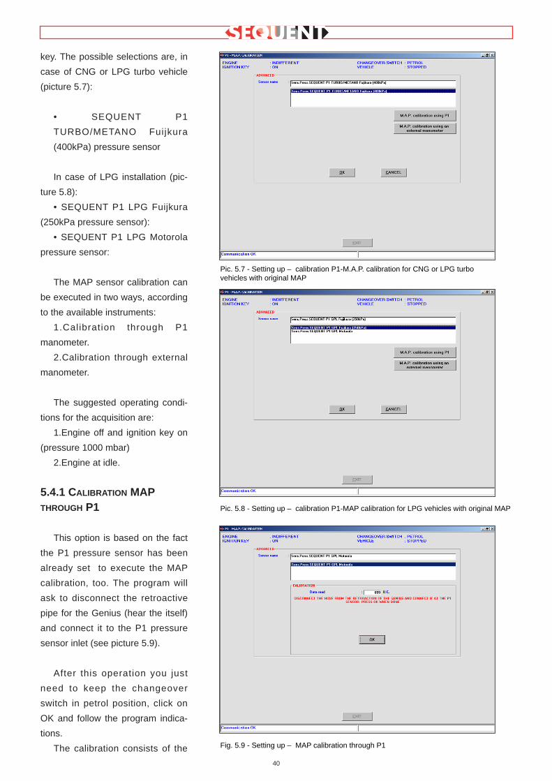
key. The possible selections are, in
case of CNG or LPG turbo vehicle
(picture 5.7):
• SEQUENT P1
TURBO/METANO Fuijkura
(400kPa) pressure sensor
In case of LPG installation (pic-
ture 5.8):
• SEQUENT P1 LPG Fuijkura
(250kPa pressure sensor):
• SEQUENT P1 LPG Motorola
pressure sensor:
The MAP sensor calibration can
be executed in two ways, according
to the available instruments:
1.Calibration through P1
manometer.
2.Calibration through external
manometer.
The suggested operating condi-
tions for the acquisition are:
1.Engine off and ignition key on
(pressure 1000 mbar)
2.Engine at idle.
5.4.1 CALIBRA TION MAPTHROUGH P1
This option is based on the fact
the P1 pressure sensor has been
already set to execute the MAP
calibration, too. The program will
ask to disconnect the retroactive
pipe for the Genius (hear the itself)
and connect it to the P1 pressure
sensor inlet (see picture 5.9).
After this operation you just
need to keep the changeover
switch in petrol position, click on
OK and follow the program indica-
tions.
The calibration consists of the
40
Pic. 5.7 - Setting up – calibration P1-M.A.P. calibration for CNG or LPG turbovehicles with original MAP
Pic. 5.8 - Setting up – calibration P1-MAP calibration for LPG vehicles with original MAP
Fig. 5.9 - Setting up – MAP calibration through P1

following steps (picture 5.10):
1.Turn the vehicle ignition key
on and leave the engine off.
2.Click on Acquire: this opera-
tion will last few seconds.
3.Switch the engine on at idle
(see picture 5.11).
4.Click on Acquire: this opera-
tion will last few seconds.
At this point you just need to
confirm the calibration clicking OK
and after Exit, you will be asked to
confirm the set adjustments:
answer positively.
5.4.2 MAP CALIBRA TION
THROUGH EXTERNAL
PRESSURE GAUGE
It is possible to execute this
option only when you have an
external pressure gauge or a diag-
nosis equipment (often the diagnos-
tic handle computer AEB214 is
enough); when possible, this
method is surely the one allowing a
more precise, easier and faster cali-
bration.
The calibration consists in the
acquisition of two different vehicle
operation conditions and following
extrapolation of the characteristic
through an easy linearization.
Note: the diagnostic equipment
often gives the suction manifold
pressure in kPa (Kilo Pascal)
instead of mbar (mill ibar) as
required by the program.
The conversion formula to obtain
the value in kPa, Knowing the mbar
one, is the following:
mbar value = kPa value * 10
For example 42 kPa correspond
to 420 mbar.
The calibration procedure con-
sists of the following steps (see pic-
41
Pic. 5.10 - Setting up – MAP calibration through P1, first value acquisition
Pic. 5.11 - Setting up – MAP calibration through P1, second value acquisition
Pic. 5.12 - Setting up – MAP calibration through external pressure gauge

ture 5.12):
1.Turn the vehicle ignition key on
and leave the engine off;
2.Click on Acquire: this operation
will last few seconds.
3.In Physical 1, introduce the
mbar value read by the pressure
gauge (or by the diagnostic equip-
ment) and click on OK (see picture
5.13).
4.Switch the engine on at idle
(see picture 5.14).
5.Click on Acquire: this operation
will last few seconds.
6.In Physical 2 , introduce the
mbar value read by the pressure
gauge (or by the diagnostic equip-
ment) and click on OK (see picture
5.15).
At this point you just need to
confirm the calibration clicking OK
and after Exit. You will be asked to
confirm the set adjustments.
42
Pic. 5.13 - Setting up – calibration MAP calibration through external pressure gauge, first value acquisition
Pic. 5.14 - Setting up – calibration MAP calibration through external pressure gauge, second value acquisition
Pic. 5.15: Setting up – calibration MAP calibration through external pressure gauge,second value introduction

5.5 CHANGE-OVER
This screen allows to modify the
parameters for the petrol-gas
change-over. Two sections have
been displayed in red (see picture
5.16):
1.Cold engine
2.Warm engine
The first is necessary to the
gas/petrol change-over calibration
when the vehicle is cold (for exam-
ple after a long stop without starting
the engine); the second for the
change-over calibration when the
engine is warm (for example when
you start the engine after a short
stop) The reference temperature is
the genius one or, in case the vehi-
cle original sensor is connected
and calibrated, the engine cooling
water one.
In the Cold Engine section you
can introduce the following data:
• Change-over temperature
higher than: it corresponds to
the temperature we have to
achieve after the set time to
execute the change-over.
• Change-over Delay: it corre-
sponds to the waiting t ime
before verifying the change-over
temperature.
• Similar paragraphs are includ-
ed in the Warm Engine section.
Usually, in the Cold Engine sec-
tion, it is better to set a low change-
over temperature and a medium
long delay while in the Warm
Engine one it is better to set an
higher change-over temperature
and a lower delay.
Besides some parameters modi-
fication, the ADVANCED key per-
mits to execute the petrol/gas
change-over which normally occurs
if there is no gas in the tank or if the
gas temperature is too low.
This screen parameters have to
be modified only with BRC techni-
cians support.
The configurable parameters
(fig. 5.16a) are:
• MAP maximum value for the
change-over: it corresponds to
the manifold pressure value
under which it is possible to
change from gas to petrol.
• RPM maximum value for the
change-over: it corresponds to
the rpm value under which it is
possible to change from gas to
petrol.
• Petrol change-over tempera-
ture: it corresponds to the tem-
perature threshold under which
the petrol change-over occurs. it
43
Pic. 5.16 - Setting up – change-over parameters calibration
Fig. 5.16a - Setting up - change-over petrol parameters calibration

is possible to deactivate this
change-over introducing –41 °C
in this table.
• Minimum DeltaP: It corre-
sponds to the DeltaP value (dif-
ference between gas P1 pres-
sure and MAP) under which the
petrol change-over occurs.
• Maximum Duty cycle for the
change-over: It corresponds to
the gas injectors duty cycle
threshold over which the
change-over occurs.
• Waiting time for gas change-
over: indicates the time between
the conditions recognition allow-
ing to return to gas operation
and the real change-over.
• Waiting time for petrol change-
over: indicates the time between
the recognition of a possible
petrol change-over cause and
the real change-over.
• Waiting time for end gas warn-
ing signal: indicates the time
between the conditions recogni-
t ion of the gas end and the
warning signal.
• Fuel consumption threshold:
according to the type of installa-
tion and the injectors number,
this threshold is useful to know
when 0,5 petrol litres have been
consumed after the petrol
change-over.
5.6 TIP IN AND TIP OUT
When necessary, tip in and tip
out screens allow to calibrate the
setting up parameters to improve
the driving.
Let’s analyse the tip in screen.
In the upper part the rpm thresh-
olds subdividing the tip in are dis-
played in red. The below cells can
be set by the user and indicate the
tip in entry threshold based on the
TPS and rpm signals. A red arrow
indicates what is the condition of
the vehicle and consequently what
are the cells to be modified to
change the transient. The value to
introduce is always a positive one
and it can be understood from the
read one in the TPSFHPos% cell.
This latter indicates every second
the filtered TPS value; you just
have to read the inside value, dur-
ing a tip in you need to modify and
introduce it in the entry threshold
cells, where there is the tip in start-
ing condition.
For example, if you wish to mod-
ify a tip in at 1000 rpm, it is neces-
sary to modify the fifth and sixth
cell, identified by 900 and 1150 rpm
even if the tip in exceed this rpm
threshold, introducing as entry
threshold a value which is the same
to the one contained in the
TPSFHPos cell.
With an entry threshold value of
1000 in a cell concerning a certain
condition, the transients will be
deactivated for that condition.
The Transient Flow cells allow
to introduce a flow value to be
added to the tip in flow. A positive
one will rich the tip in while a nega-
tive one will make it lean. To give
an idea of the value to be intro-
duced, refer to the flow values dis-
played in the self-learning screen,
near the tip in.
The other parameters in the
screen are:
• Tip in exit threshold: indicates
the TPS threshold for the tip in
exit and usually it is negative:
the exit usually occurs with a
deceleration.
• Dissolving time: it is the con-
nection time to go from the tip in
flow to the one usually required
by the vehicle. This time begins
at the end of the upkeep one
and it is expressed in 1/1000 of
second, too.
• Petrol tip in %: indicates how
much the immediate petrol cor-
rection enter the gas tip in, that
is how much influence the petrol
ECU tip in has on the gas
44
Pic. 5.17 - Setting up – Tip in calibration

behaviour. 1000 corresponds to
use all the petrol contribution,
decreasing the value the contri-
bution proportionally decreases.
• Tip in condition: indicates the
vehicle condition.
Let’s analyse tip out in screen
(picture 5.18):
In the upper part the rpm thresh-
olds subdividing the tip out are dis-
played in red. The below cells can
be set by the user and indicate the
tip out entry threshold based on the
TPS and rpm signals. A red arrow
indicates what is the condition of
the vehicle and consequently what
are the cells to be modified to
change the tip out. The value to
introduce is always a positive one
and it can be understood from the
read one in the TPSFHNeg% cell.
This latter indicates every second
the filtered TPS value; you just
have to read the inside value, dur-
ing a tip out you need to modify and
introduce it in the entry threshold
cells, where there is the tip out
starting condition.
For example, if you wish to mod-
ify a tip out at 1000 rpm, it is neces-
sary to modify the fifth and sixth
cell, identified by 900 and 1150 rpm
even if the tip out exceed this rpm
threshold, introducing as entry
threshold a value which is the same
to the one contained in the
TPSFHNeg% cell.
With an entry threshold value of
1000 in a cell concerning a certain
condition, the tip out will be deacti-
vated for that condition.
The tip out Flow cells allow to
introduce a flow value to be added
to the tip out flow. A positive one
will rich the tip out while a negative
one will make it lean. To give an
idea of the value to be introduced,
refer to the flow values displayed in
the self-learning screen, near the
tip out.
The other parameters in the
screen are:
• Tip out exit threshold: indicates
the TPS threshold for the tip out
exit and usually it is negative:
the exit usually occurs with a
deceleration.
• Upkeep time: indicates the tip
out time. It is indicated in 1/1000
of second that is 1 second 0
1000.
• Dissolving time: it is the con-
nection time to go from the tip
out f low to the one usually
required by the vehicle. This
time begins at the end of the
upkeep one and it is expressed
in 1/1000 of second, too.
• Petrol tip out %: indicates how
much the immediate petrol cor-
rection enter the gas tip out, that
is how much influence the petrol
ECU tip out has on the gas
behaviour. 1000 corresponds to
use all the petrol contribution,
decreasing the value the contri-
bution proportionally decreases.
• Tip out condition: indicates the
vehicle condition.
5.7 SELF-LEARNING
During standard operation con-
ditions, after the mapping, the ECU
corrects the light calibration inaccu-
racies and follows the slow varia-
tions due to the system ageing, set-
ting up lost or the slow gas and
petrol components deterioration.
This is the self-learning function.
It is very important to well under-
stand the difference between self-
mapping and self-learning. The
self-mapping is executed only one
time during the vehicle installation
while the self-learning will work for
the whole gas installation life, keep-
ing the operation and calibration
conditions the best as possible.
The self-learning screen is use-
ful to verify and correct the center-
45
Pic. 5.18 - Setting up – Tip out calibration

ing of a map. There are three files:
• Petrol Map
• GAS Map
• Condition Map
To go from a file to another you
just have to click on the icon of the
file you need to display.
Each file consists of a table with
16 lines and 16 columns. Each cell
contains a contains the memorise
operating point according to rpm
and manifold pressure (MAP).
Particularly, the petrol map memo-
rised the petrol injectors duty cycle;
the gas map contains the memo-
rised gas flow according to the
petrol map and the extrapolation
algorithms while the condition map
contains the system operation con-
ditions according to the lambda
control carried out with petrol. It is
possible to set three different oper-
ation conditions:
• Closed loop = 4, for the areas
regularly checked by the oxygen
sensor.
• Open loop = 5, for the areas
which are not under the oxygen
sensor control.
• Indefinite = 7, for the “border”
areas between open loop (full
load) and closed loop (con-
trolled oxygen sensor) that are
those areas when you can have
open loop or closed loop condi-
tions according to the engine
load.
According to the selected condi-
tion the colour of the cells in the
petrol and gas map will be different:
• Green: for closed loop cells.
• Red: for open loop cells
• Yellow: for indefinite cells
The white ones (picture 5.19)
indicates the operation area
where the system is working. To
manually modify a cell value,
click on it, push the space-bar,
introduce the new value and
click on enter key.
The other parameters represent:
• RPM and MAP: they respec-
tively indicate the engine rota-
tion condition and the suction
manifold pressure (MAP)
• Petrol inj. DC: indicates the
petrol injection duty cycle
instantaneously taken from the
petrol injectors.
• Reference DC: indicates the
petrol injection duty cycle
expected by the map for the
specific operation point.
• GAS inj. DC: indicates the gas
injectors duty cycle.
• % error: indicates the average
difference between the petrol
injectors duty cycle and the ref-
erence one. It is positive if the
petrol injectors duty cycle is
higher that the reference one.
This has to be interpreted as the
signal of a lean gas map or of a
petrol map with too low values.
A graphic showing the oxygen
sensor behaviour is represented
hereunder and it is very useful to
identify the open loop and closed
loop areas.
The “Cancel last Digit” key
allows to settle the previous values
again.
At the bottom of the screen
there are two sliding bars. On the
left we have petrol self-learning
speed; on the right the gas self-
learning speed . These allow to
modify, decelerating and accelerat-
ing, the system self-learning algo-
rithms. For each parameter we
have 6 different speeds:
• Very fast
• Fast
• Medium
• Slow
• Very Slow
• Stopped
The control of a map centering
reliability consists of positioning in
different operation points with RPM
and MAP constant and check the
46
Pic. 5.19 - Setting up – self-learning

%Error value. A map can be con-
sidered centred is the error is less
than 5%. A not centred map or
areas could be brought to a good
level with a manual intervention or
reviewing the cells keeping the con-
ditions more constant as possible in
order to take the %error to a value
lower than 5%.
If some changes occur, when
leaving this screen you will be
asked to confirm them and they will
be saved later in the User_Maps
file and sent to the ECU.
47

48
6.1 DATA DISPLAY
Clicking on DIAGNOSTIC key
at the bottom of the main screen
and selecting Data display in the
left buttons, we enter the page
shown in picture 6.1 where it is
possible to display the different
ECU operat ion parameters as
numbers or with a graphic.
As indicated in picture 6.1 the
numerical values are listed on the
left while the graphs are more or
less in the centre. These latter can
be minimum one or maximum four
or even zero (pictures 6.1, 6.2,
6.3, 6.4 and 6.5)
To introduce a new graphic or
take one away you just have to
cl ick twice the corresponding
numerical value. When there are
four graphs, to add another it is
necessary to take away at least
one.
6. DIAGNOSTIC
Pic. 6.1 - Data display with a graphic
Pic. 6.2 - Data display with two graphics
Pic. 6.3 - Data display with three graphics

49
At the top of the graphs and the
numbers there are 6 square but-
tons, each with a particular func-
t ion described later. With the
mouse pointer on them, a writing
explaining the function will appear
for a few seconds. These functions
allow to execute file acquisition of
data and displayed parameters, to
change the numerical data list dis-
played on the screen choosing the
most interesting ones from the list,
to modify the list of the values
which will be saved in file choosing
the most interesting ones.
6.1.1 STORAGE PARAMETERS
The f irst left key with a f i le
allows to change the storage para-
meters that is the position where
the acquisition file creating in this
page will be saved. Clicking on the
key, the page in picture 6.6 will be
opened.
the same effect is obtained by
selecting “File” and then “Record
Parameters” from the menu bar (at
the top left). In the centre of the
screen, at the top, there is a big
file with all the previous acquisi-
tions characteristics.
Immediately under there is a
table titled “Data Sheet” where
there are different files to fill up:
you have to compulsori ly set
trademark, Model and Plate. the
others (Year, engine number, ECU
type, Power, Type of installation,
Note) are optional and wil l be
stored as a reminder in the
acquired file.
Let’s imagine to fill in trademark
with Fiat, Model with “Stilo 1.6i
16V (182B6000) Euro4”, and Plate
with “AJ280CN” (plate number); in
this case the acquisition file will
Pic. 6.4 - Data display with four graphics
Pic. 6.5 - Data display without graphic
Pic. 6.6 - Diagnostic > Data display > Storage Data

50
have the fol lowing name and
address: ”
C:\Programs\SEQUENT\ARCHIVI
\DIR_DATI\Fiat\Sti lo 1.6i 16V
( 1 8 2 B 6 0 0 0 )
Euro4\AJ280CN.ACQ” (the posi-
tion could vary according to the
computer characteristics and to
the file where SEQUENT program
is installed).
Clicking on “Store” key, the file
where you will execute the data
acquisition will be created. Clicking
on “Exit”, data will be not stored
and the system returns to the pre-
vious page.
Please note that the new
record is stored in the top cell in
order to select it next time without
having to digi t the complete
address. Selecting it all the data
will appear in the cells, including
the notes you decided to add.
6.1.2 BEGINNING/RESTARTING
RECORD
When you push the second key
on the left with a red triangle with
the point to the r ight (as the
recorder PLAY button), the data
acquisition starts (see previous
paragraph to know where data will
be stored).
When the data acquisition is
active, the key changes into two
paral lel vert ical l ines (as the
recorder PAUSE button). If you
click on the key during this condi-
tion, the acquisition will be stopped
and the key becomes a triangle
again. Clicking it again, the acqui-
sition restarts adding new data to
the previous ones, without can-
celling them.
The same operations can be
executed by selecting on the bar
menu (at the top left) “Record” and
then “Beginning/Restarting record”
or by simply click on SHIFT+F2,
SHIFT+F5, SHIFT+F9 on the key-
board.
It is possible to stop the record
anytime by clicking on the STOP
key (a red square as the recorder
STOP button). Cl icking again
START or PLAY, the acquisition
starts again adding new data to
the previous ones, without can-
celling them.
6.1.3 GRAPHS BLOCKING
The forth left key can block dis-
played graphs and numerical val-
ues. First it contains a graph with a
red cross on. Clicking on it the
graphs will be blocked and the
numerical values do not change;
the key will contain a graph with-
out red cross.
By clicking on the key again,
the graphs will be deleted and you
have to start again from the begin-
ning while the numbers start again
to change.
6.1.4 SETTING
The fifth key from the left, at the
top of the data display page, is
used to choose what are the
numerical data to display and what
are the ones to be stored during
the acquisition.
As shown in picture 6.7, near
each value there are two cells
where the t ick mark has to be
added: the first refers to the dis-
played value. Selecting or dese-
lecting the cell, you add or remove
the data from the column. The
minimum data number is 1 and the
maximum is 10. If you already
have 10 values, you will have to
remove one to add another.
Under “Recorded” there are
some cells to select the data to
acquire and store on .ACQ file.
you can store the number you pre-
fer, even all, if you wish. Take care
that more data you have more the
acquisition file becomes long. In
the same way, the file enlarges
considering the acquisition length.
Pic. 6.7 - Diagnostic > Data display > Channel setting

51
6.1.5 PAGE EXIT
Use the sixth key from the left,
at the top of the data display page,
to leave the page.
The same could be obtained
with EXIT key at the bottom centre
of the page or by clicking the enter
key when framed in a broken line.
6.2 ACTUATORS TEST
When the ECU has been pro-
grammed with a basic map it is
important to verify the correspon-
dence of the injectors, the signal
coming from the petrol injector 1
has to be the same of the gas
injector 1, and this for all the injec-
tors.
Possible errors for this connec-
tion do not create big problems for
the vehicle operation during sta-
bilised running, but are strongly
perceptible during t ip in and
change-over.
The inversion of two injectors is
very dangerous during change-
over as, for a certain period, one
cylinder will be fed with both petrol
and gas while the other one will
not receive any fuel.
In picture 6.8 we have a cor-
rect injectors connection while in
picture AM45 gas injector 1 and 2
have been reversed.
In the SEQUENT system the
change-over in carried out in order
to change-over one injector each
time to make the petrol to gas pas-
sage milder and vice versa. This
means that in a 4 cylinder vehicle
the petrol feeds three cylinders
and the other with gas, then two
cylinders with petrol and two with
gas, then one with petrol and three
with gas till reaching a full gas
operation for all cylinders. Some
engine cycles which could be set
from installers program (normally
3) have to be executed between
an injector change-over and
another one.
In the picture 6.8 at the
change-over happens the follow-
ing:
• The petrol 1 injector is cut and
the gas 1 injector is piloted.
• After 3 injections the petrol 2
injector is cut, too and the gas 2
injector is piloted
• After other 3 injections the
petrol 3 injector is cut, too and the
gas 3 injector is piloted.
• Again After other 3 injections
the petrol 4 injector is cut, too and
the gas 4 injector is piloted.
In this case during the change-
over all the cylinders are continu-
ously fed with a one and only fuel.
Pic. 6.8 - Correct installation example
Pic. 6.9 - Wrong installation example
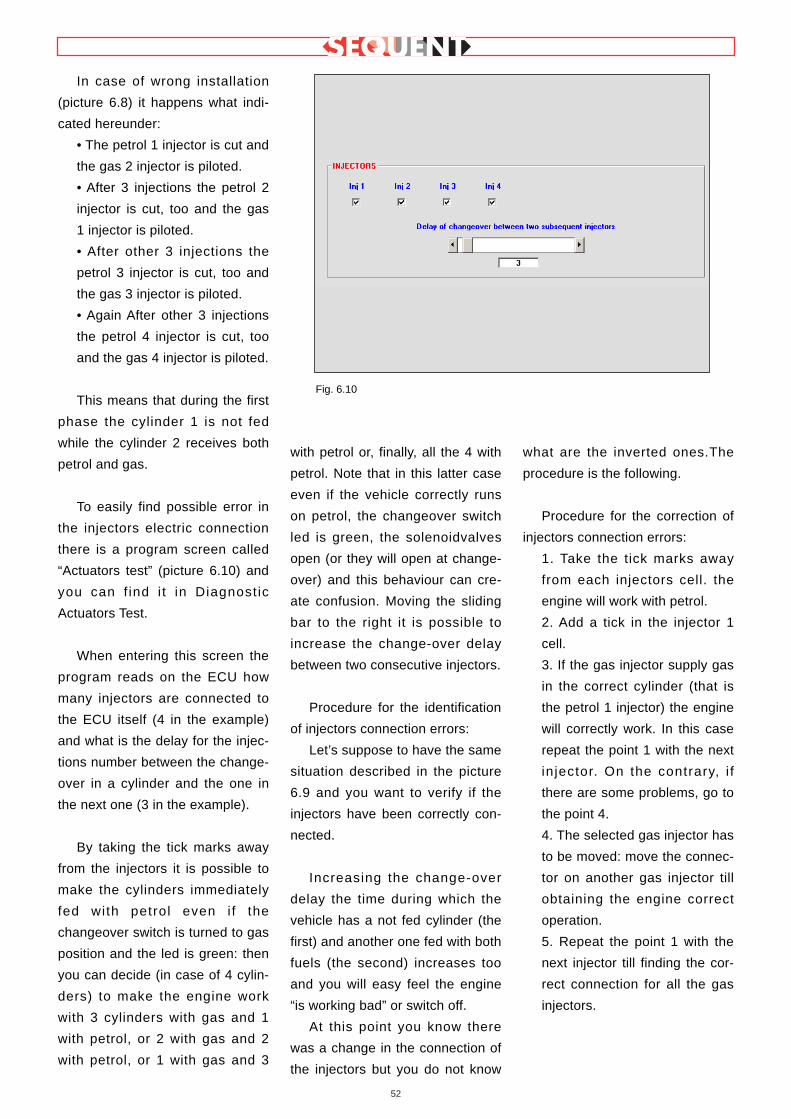
52
In case of wrong installation
(picture 6.8) it happens what indi-
cated hereunder:
• The petrol 1 injector is cut and
the gas 2 injector is piloted.
• After 3 injections the petrol 2
injector is cut, too and the gas
1 injector is piloted.
• After other 3 injections the
petrol 3 injector is cut, too and
the gas 3 injector is piloted.
• Again After other 3 injections
the petrol 4 injector is cut, too
and the gas 4 injector is piloted.
This means that during the first
phase the cylinder 1 is not fed
while the cylinder 2 receives both
petrol and gas.
To easily find possible error in
the injectors electric connection
there is a program screen called
“Actuators test” (picture 6.10) and
you can f ind i t in Diagnost ic
Actuators Test.
When entering this screen the
program reads on the ECU how
many injectors are connected to
the ECU itself (4 in the example)
and what is the delay for the injec-
tions number between the change-
over in a cylinder and the one in
the next one (3 in the example).
By taking the tick marks away
from the injectors it is possible to
make the cylinders immediately
fed with petrol even i f the
changeover switch is turned to gas
position and the led is green: then
you can decide (in case of 4 cylin-
ders) to make the engine work
with 3 cylinders with gas and 1
with petrol, or 2 with gas and 2
with petrol, or 1 with gas and 3
with petrol or, finally, all the 4 with
petrol. Note that in this latter case
even if the vehicle correctly runs
on petrol, the changeover switch
led is green, the solenoidvalves
open (or they will open at change-
over) and this behaviour can cre-
ate confusion. Moving the sliding
bar to the right it is possible to
increase the change-over delay
between two consecutive injectors.
Procedure for the identification
of injectors connection errors:
Let’s suppose to have the same
situation described in the picture
6.9 and you want to verify if the
injectors have been correctly con-
nected.
Increasing the change-over
delay the time during which the
vehicle has a not fed cylinder (the
first) and another one fed with both
fuels (the second) increases too
and you will easy feel the engine
“is working bad” or switch off.
At this point you know there
was a change in the connection of
the injectors but you do not know
what are the inverted ones.The
procedure is the following.
Procedure for the correction of
injectors connection errors:
1. Take the tick marks away
from each injectors cell. the
engine will work with petrol.
2. Add a tick in the injector 1
cell.
3. If the gas injector supply gas
in the correct cylinder (that is
the petrol 1 injector) the engine
will correctly work. In this case
repeat the point 1 with the next
injector. On the contrary, i f
there are some problems, go to
the point 4.
4. The selected gas injector has
to be moved: move the connec-
tor on another gas injector till
obtaining the engine correct
operation.
5. Repeat the point 1 with the
next injector till finding the cor-
rect connection for all the gas
injectors.
Fig. 6.10

53
6.3 ECU VERSION
With DIAGNOSTIC key at the
bottom of the main screen and
selecting ECU VERSION among
the left keys, you enter the page of
picture 6.11 with the parameters
identifying the software type, the
data and other parameters regard-
ing the ECU programming.
6.3.1 PARAMETERS DESCRIP-TION
6.3.1.1 ECU Code
It is the code of the component
which represents this particular
type of ECU. For example the one
in the picture is “DE813001-00-00”
and identify the first version of the
FLY SF ECU for 4 injectors.
This code is divided in a main
one (DE813001) for the compo-
nent (FLY SF ECU for 4 injectors),
and two sub-codes divided with a
stroke identifying the main and
secondary hardware revision.
6.3.1.2 Loader version
Identify the loader version in
the ECU memory. It is displayed
as a letters and numbers
sequence as the following: “KER-
FS 0113”. The last four numbers
represents the version (in this
case 113). Higher is this number
and more recent and improved will
be the loader.
6.3.1.3 Software version
It is the real software contained
in the ECU. It is composed by 5
letters + 3 numbers + 3 numbers.
The first 5 letters indicates the
software, the other 3 numbers the
real software version (higher is this
number and more recent and
improved wil l be the program)
while the last 3 indicates the hard-
ware version.
6.3.1.4 Map version
It is the ECU map version (file
.AAP) (not the calibrations version
that is .FSF). For BRC maps it is
at least 1: this number is increased
each time BRC develop a new ver-
sion.
For the maps developed by the
technician this number is always 0.
6.3.1.5 Vehicle code
This number is paired to each
vehicle developed and confirmed
by BRC. Its value is 65535 if the
map has been developed by the
technician with the guided person-
alised procedure. If the technician
creates a new map by modifying a
BRC one, without using the guided
personalised procedure, the BRC
original vehicle code won’t be
change.
6.3.1.6 Calibrations V ersion
It is the ECU calibrations ver-
sion (file .FSF) (not the mapping
version that is .AAP). For BRC
maps it is at least 1: this number is
increased each time BRC develop
a new version.
For the maps developed by the
technician this number is always 0.
6.3.1.7 First programming date
It is the date in which the ECU
has been programmed for the first
time by the technician. After the
first one, this date won’t change
for the ECU all life long.
6.3.1.8 Programming code
It identifies the type of program
used in the PC to execute the last
ECU programming.
Usual ly i t could be
“PROG_INS”, to indicate
SEQUENT technician program has
been used.
Pic. 6.11 - Diagnostic – ECU Version
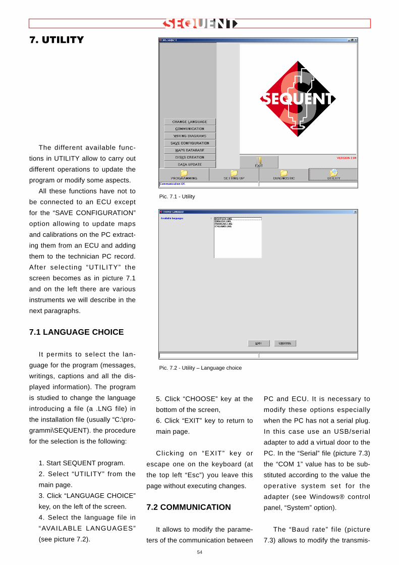
54
The different available func-
tions in UTILITY allow to carry out
different operations to update the
program or modify some aspects.
All these functions have not to
be connected to an ECU except
for the “SAVE CONFIGURATION”
option allowing to update maps
and calibrations on the PC extract-
ing them from an ECU and adding
them to the technician PC record.
After select ing “UTILITY” the
screen becomes as in picture 7.1
and on the left there are various
instruments we will describe in the
next paragraphs.
7.1 LANGUAGE CHOICE
I t permits to select the lan-
guage for the program (messages,
writings, captions and all the dis-
played information). The program
is studied to change the language
introducing a file (a .LNG file) in
the installation file (usually “C:\pro-
grammi\SEQUENT). the procedure
for the selection is the following:
1. Start SEQUENT program.
2. Select “UTILITY” from the
main page.
3. Click “LANGUAGE CHOICE”
key, on the left of the screen.
4. Select the language file in
“AVAILABLE LANGUAGES”
(see picture 7.2).
5. Click “CHOOSE” key at the
bottom of the screen,
6. Click “EXIT” key to return to
main page.
Cl icking on “EXIT” key or
escape one on the keyboard (at
the top left “Esc”) you leave this
page without executing changes.
7.2 COMMUNICATION
It allows to modify the parame-
ters of the communication between
PC and ECU. It is necessary to
modify these options especially
when the PC has not a serial plug.
In this case use an USB/serial
adapter to add a virtual door to the
PC. In the “Serial” file (picture 7.3)
the “COM 1” value has to be sub-
stituted according to the value the
operat ive system set for the
adapter (see Windows® control
panel, “System” option).
The “Baud rate” file (picture
7.3) allows to modify the transmis-
7. UTILITY
Pic. 7.1 - Utility
Pic. 7.2 - Utility – Language choice

55
sion speed. If there are not partic-
ular problems, we suggest to leave
the maximum speed of 19200
Baud, with whom you have the
minimum times of the ECU pro-
gramming. The other programming
speeds are 10400 Baud and 9600
Baud (standard ones).
Another interesting parameter
is the “Waiting time between 2 fol-
lowing messages”. Decreasing this
time you obtain higher speed for
the ECU programming but higher
possibilities the communication
fail, too. The suggested standard
value is 150 ms, except in case of
problems.
The “Fast init. hooking” key is
used to select the initialisation type
has to be used to start the commu-
nication between PC and ECU.
Usually it has to be selected.
The options appearing clicking
on “ADVANCED” has to be
changed only in case of problems
and only with the help of BRC
technicians or qualified personnel.
In case these parameters have
been modified causing the impos-
sibility to dialogue with the ECU,
restore standard values. You can
know the value of each cell placing
the mouse pointer on them: a
small cell with the standard value
will be displayed and will disap-
pear when moving the pointer.
To save the changes and return
to the main page, click “SAVE” key
at the bottom of the screen. To
leave without saving the modifica-
tions and return to the main page,
click “EXIT” key or the escape one
on the keyboard (at the top left
“Esc”).
7.3 ELECTRICAL PLANS
Clicking on this key you enter
the electrical plans file. The plan is
available in a PDF format opening
with “Adobe Acrobat® ReaderTM ”
(1) program which has to be
installed in the computer (see note
(1)). Use the SEQUENT software
installation CDROM and follow this
procedure:
1.Switch the PC on.
2.Introduce the CDROM.
3.Wait for the automatic start of
the installation program (if it
does not happen go to note
hereunder).
4.Cl ick on “Instal l Acrobat
Reader” key.
5.Follow the installation Guided
Procedure.
NOTE: the automatic starting of
SEQUENT program installation
introducing the CDROM depends
on the PC setting. In case the
installation does not begin, start
the “Setup” program in the CD
ROM main file (Click on Start >
Execute, write “D:\Setup.exe” and
click on OK. “D” represents the
CDROM. If it is different, change it
with the correct letter.
Wait for the automatic start of
the installation program (if it does
not happen go to note hereunder).
The procedure to display an
electrical plan is the following:
1. Select “UTILITY” in the main
page.
2. Cl ick on “ELECTRICAL
PLANS” on the left.
3. Click twice on “BRC_MAPS”
file in the file window (at the top
left).
4. Select “LPG” o CNG”( see
picture 7.4).
5. Using the mouse or the
arrows, select the trademark,
model and ECU type to get the
electrical plan.
Pic. 7.3 - Utility – communication

56
6. In the text cell, in the centre
of the screen, the list of avail-
able electrical plans will be dis-
played. If the cell is empty it
means there are not available
plans.
7. If there is at least one plan,
select it with the mouse and the
name of the selected file will be
displayed in the “Electr ical
Plans” text cell (blue writing).
8. Click on “VIEW” key at the
bottom of the screen.
9. Wait for the start of the
“Adobe Acrobat® ReaderTM ”
program, displaying the desired
plan.
10. After the plan consultation,
close the program.
“Adobe Acrobat® ReaderTM ”
guide is available starting the pro-
gram (START key of Windows bar,
the PROGRAMS and f inal ly
ACROBAT READER) choosing “?”
and then “Reader Guide”.
To quit the SEQUENT program
electrical plans and go to the main
page, click on “EXIT” key at the
bottom of the screen or the escape
one (“Esc” at the top left of the
keyboard).
(1) PDF format (Portable
Document Format) Adobe® repre-
sents the standard for the elec-
tronic documents distribution all
over the world. PDF Adobe is a
universal file format which keep
unchanged all characters, the for-
mat, colours and images indepen-
dently of the application and plat-
form used to create them. PDF
Adobe files are compact ones and
can be shared, displayed, consult-
ed and printed by everybody
thanks to the free Adobe Acrobat®
Reader™ utility available in the
Adobe® site (www.adobe.i t in
Italian and www.adobe.com in
English language).
7.4 CONFIGURATION SAVE
This key allows to extract the
data contained in the ECU and to
save them on the PC as a new
map. By doing this it is possible to
increase the list of convertible
vehicles without creating updating
disks and to operate on every
vehicles modifying maps and cali-
brations even if the specific map is
not available on the PC.
The procedure is this one (see
picture 7.5):
1. Connect the PC to the SLY
SF ECU with the suitable com-
munication harness.
2. Start SEQUENT program.
3. Switch the ignition key on.
4. Select “UTILITY” in the main
page.
5. Click on “CONFIGURATION
SAVE”, on the left of the
screen.
6. If the communication is not
active (no “Communication OK”
writing at the bottom left) wait
and try again. If i t does not
start, verify the connection and
Pic. 7.4 - Utility – ELECTRICAL PLANS

57
the key contact.
7. Select “LPG” or “CNG” in
the “USER_MAPS” file, (the
record window at the top left).
8. Select the file concerning
trademark, model and ECU
type where you wish to save
the new map and calibration. If
the file does not exist, introduce
the above data again in the
suitable cells and create a new
one.
9. In the text cell identified by
the blue “FILE:” writing, intro-
duce a name easy to keep in
mind to save the map and cali-
bration files in the computer
record.
10. Click on “SAVE” key at the
bottom right.
11. Wait for the procedure end
confirmed with the red mes-
sage “CONFIGURATION SAV-
ING CORRECTLY ENDED”.
To quit “SAVE CONFIGURA-
TION” and return to the main
page, click on “EXIT” key at the
bottom of the screen or the escape
one (“Esc” at the top left of the
keyboard).
7.5 MAPS DATABASE
I t al lows to modify the user
maps record changing the name of
the fi les, moving, deleting and
copying them (picture 7.6).
• To change a record name
(relating to the trademark, the
model and the ECU type) follow
this procedure:
1. Select “UTILITY” in the main
page.
2. Cl ick on “MAPS DATA-
BASE”, on the left of the
screen.
3. Cl ick twice on “USER
MAPS”.
4. Select “LPG” o CNG” in the
record window.
5. Choose the file to name and
select it using the mouse or the
arrows.
6. Click on “RENAME” at the
bottom of the screen.
7. Introduce the new name.
8. Click on enter key.
• To erase a file (relating to the
trademark, the model and the ECU
type) follow this procedure:
1. Select “UTILITY” in the main
page.
2. Cl ick on “MAPS DATA-
BASE”, on the left of the
screen.
3. Click twice on “USER MAPS
(at the top left).
4. Select “LPG” or CNG”.
5. Choose the file to name and
select it using the mouse or the
arrows.
Fig. 7.5 - Utility - Save configuration
Pic. 7.6 - Utility - MAPS RECORD

58
6. Click on “ERASE” at the bot-
tom of the screen.
7. A message will ask to con-
f i rm: a posit ive answer wi l l
erase the file from the record.
8. If a file has been erased, a
new message will confirm it.
Click on “OK” or enter key to
continue.
BE CAREFUL!: The erase
operation is very dangerous and
can cause the loss of important
data contained in the users record.
For example if you select a file
relating to a trademark (i.e “Fiat”)
and confirm the erasure, ALL the
files of ALL models and ALL ECUs
will be removed (that is all “Fiat”
vehicles contained in the users
record).
• To create a new file (relating
to the trademark, the model and
the ECU type) follow this proce-
dure:
1. Select “UTILITY” in the main
page.
2. Cl ick on “MAPS DATA-
BASE”, on the left of the screen.
3. Cl ick twice on “USER
MAPS”.
4. Select “LPG” or CNG”.
5. If you wish to create a file for
a new trademark ( i .e.
“LEXUS”), go to step 8.
6. If you wish to create a file for
a new model (i.e. “Punto 1200
8V” in the “Fiat” file) go to step
9.
7. sIf you wish to create a file
for a new type of ECU (i .e.
“MagMar49F”) go to step 15.
8. Click on “CREATE NEW”. A
new file relating to the trade-
mark named “New_trademark”
will appear.
9. Write the trademark name
and click on enter to change it.
10. Go to step 18.
11. Select the file relating to the
trademark (i.e. “Fiat”).
12. Click on “CREATE NEW”. A
new file relating to the model
named “New_model” wi l l
appear.
13. Write the model name and
click on enter to change it.
14. Go to step 18.
15. Select the file relating to the
trademark (i.e. “Fiat”), and then
the model.
16. Click on “CREATE NEW”. A
new file relating to the type of
ECU named “New_ECU” will
appear.
17. Write the ECU name and
click on enter to change it.
18. The new created f i le is
empty now. To introduce the
data, follow the guided person-
alised programming or setting
up procedure.
• To copy a model or petrol
ECU type file in another posi -
tion:
1. Select “UTILITY” in the main
page.
2. Cl ick on “MAPS DATA-
BASE”, on the left of the
screen.
3. Cl ick twice on “USER
MAPS”.
4. Select “LPG” or CNG”.
5. If you with to move a trade-
mark file (i.e. all “Fiat” maps)
from CNG to LPG file, or vice
versa, go to step 8.
6. If you with to move a model
file (i.e. all the contained ECU
types) from a trademark to
another one, go to step 13.
7. If you wish to copy a file of
ECU type contained in a certain
trademark file inside (LPG >
FIAT > PUNTO 1.2 8V >
MM49F – see picture 7.6) and
introduce it in another position
(LPG> PEUGEOT > 206
>………), go to step 18.
8. Select the file relating to the
trademark by using the mouse
or the arrows, (i.e “Fiat”).
9. Click on “COPY” key at the
bottom right; the key name will
change into “PASTE”.
10. Choose the new type of
installation where you wish to
copy the trademark file (i.e. if
you are copying “Fiat” , initially
contained in “LPG”, you have to
select “CNG”).
11. Click on “PASTE” at the bot-
tom right.
12. Go to step 22.
13. Select the model file you
wish to copy (i.e. select, “LPG”,
then “Fiat”, and then “Punto
1200 8V”).
14. Click on “COPY” key at the
bottom r ight: the key wi l l
change into “PASTE”.
15. Choose the trademark file
you wish to copy the model in.
16. Click on “PASTE” key at the
bottom right.
17. Go to step 22.
18. Select the petrol ECU type
file you wish to copy (i.e. select,
“LPG”, then “Fiat”, then “Punto
1200 8V”, then “MM59F”).
19. Click on “COPY” at the bot-
tom right: the key will change
into “PASTE”.
20. Choose the model f i le,
under the trademark where you
wish to copy it.
21. Click on “PASTE” key at the
bottom right.
22. The new file has been cre-

59
ated with the same name it has
when selected to be copied and
contains the same f i le. To
change inside data or name it
is necessary to follow the spe-
ci f ic procedures already
described in this guide.
To quit the maps record screen
and return to the main page, click
on “EXIT” key at the bottom of the
screen or the escape one (“Esc” at
the top left of the keyboard).
7.6 DISKS CREATION
This key allows to create disks
with the maps taken from the PC
user record in order to transfer
them in another PC. With this pro-
cedure it is not possible to transfer
the maps of the BRC record, the
software or the loader to another
PC. to update the software and
loader it is necessary to download
the updating one from BRC inter-
net site or from CDROM or disks.
Each disk created by the user
can contain various maps till the
exhaustion of the available space.
The procedure to be carried out
to transfer a map on the diskette is
the following (see picture 7.7):
1. Start SEQUENT program in
the PC containing the map you
wish to transfer.
2. Introduce an empty disk in
the PC.
3. Select “UTILITY” key in the
main page.
4. Click on “DISKS CREATION”
key.
5. In the user record select
“LPG” if it is a LPG vehicle map
or CNG if it is a CNG one.
6. Select the trademark, model
and type of ECU relating to the
map you wish to transfer.
7. If you want to deepen a self-
mapping, adding other points, it
is possible by selecting “copy
self-mapping file”. Keep in mind
that even if you are not interest-
ed in continuing a self-map-
ping, the additional files saving
is not dangerous (it only fills
more space in the disk and in
the PC hard Disk).
8. Click on “SAVE” key at the
bottom of the screen.
9. When the copy operation is
completed, you can repeat it
starting from step 4 till there are
maps to be transferred or till
you have available space. (in
this case you have to repeat
the not successfully concluded
operation after having replaced
the disk with a new one).
10. After the last copying oper-
ation, click on “EXIT” key to
return to the main page.
To transfer a map from the disk
to the new PC, follow the data
updating procedure from disk,
described in the next chapter.
7.7 DATA UPDATE
Hereunder we described the
procedures for the PC data update
from CDROM and disks, too.
These data can include maps,
software and loader for the ECU.
The updating CDROM are created
by BRC while the disks can be
created by users following the pro-
cedure described in the previous
paragraph or downloading the data
from the internet si te
http://www.brc.it. See picture 7.8.
7.7.1 UPDATE FROM CDROM
1. Start SEQUENT program (at
the bottom left corner of the
screen) and select ”Start” >
Programs > SEQUENT).
2. Introduce the CDROM in the
PC.
3. Select “UTILITY” key in the
main page.
4. Select “UPDATING DATA”
key on the left.
Pic. 7.7 - Utility - disks creation

60
5. Select CDROM (usually it is
the d: unit) near the writing “Data
updating from”.
6. Select CDROM file contain-
ing the updating file. For example
“D:\SEQUENT\updating” (instead
of D, select the CDROM name)
and continue clicking “UPDATE”
key at the bottom of the window.
7. . After the copying operation,
click on “QUIT” key to return to the
main page.
7.7.2 UPDATING FROM DISKS
In order to create one or more
updating disks of the user maps,
follow the procedure described in
the paragraph 7.6.
In order to create one or more
updating disks of maps, Sequent
software and Fly SF ECU loader
through BRC internet site, follow
the procedure described hereun-
der:
Select Sequent sect ion in
www.brc.it.
Digit your ID and PASSWORD
to enter.
The section containing the fol-
lowing operations:
1) Download the maps of all the
available vehicles.
2) Download Sequent software.
3) Download Sequent software
updating.
4) Download Fly SF ECU soft-
ware updating.
5) Download Fly SF ECU
loader updating
The below procedures are by
way of example only and refer to
download carr ied out with
Microsoft Internet Explorer 6.0.
They could suffer light differences
according to the type and version
of the used browser. in this case
refer to the browser specific indi-
cations.
7.7.2.1 Maps of all the available
vehicles
P.S. If you wish to have all the
technician maps available, you just
need to select the word maps in “
Download the maps of al l the
available vehicles”.
Select the desired diskette
clicking on DOWNLOAD key.
A window called DOWNLOAD
FILE will be opened and you can
choose where you prefer to save
the file clicking on “SAVE”.
If necessary, after the DOWN-
LOAD, close this window.
Quit Explorer application click-
ing the X at the top right.
In the chosen file look for the
previously downloaded
FIMP#_xx.exe file.
Click twice the file icon to unzip
it.
Introduce a formatted disk in
the drive A: (write a number on it in
order not to mix them up).
Answer OK, UNZIP, OK and
CLOSE to the displayed questions.
At this point the disk is ready to
be used on the technician program
to update the maps record.
7.7.2.2 Software Sequent
P.S. This software operates
only i f paired to the suitable
Hardware Key supplied by BRC.
Select “Sequent software” in
“Download Sequent software”.
Click on “Continue”
Select the desired software
installation disk by clicking DOWN-
LOAD.
A window called DOWNLOAD
FILE will be opened and you can
choose where you prefer to save
the file clicking on “SAVE”.
Pic. 7.8 - Utility – Data updating

61
If necessary, after the DOWN-
LOAD, close this window.
Quit Explorer application click-
ing the X at the top right.
In the chosen file look for the
previously downloaded SQSW-
PC#_xx.exe file.
Click twice the file icon to unzip
it.
Introduce a formatted diskin the
drive A: (write a number on it in
order not to mix them up).
Answer OK, UNZIP, OK and
CLOSE to the displayed questions.
At this point the diskette is
ready to be used to install Sequent
software in the PC.
7.7.2.3 Sequent software updat -
ing
Select “Sequent software” in
“Download Sequent software”.
Click on “Continue”
Introduce a formatted disk in the
drive A:
Select the desired software updat-
ing disk by clicking DOWNLOAD.
A window called DOWNLOAD
FILE will be opened and you can
choose where you prefer to save
the file clicking on “SAVE”.
Choose the drive A: and click on
“SAVE” key
At this point the disk is ready to be
used to update Sequent software
in the PC.
7.7.2.4 Fly SF ECU software
updating
P.S. If you wish to have the
software for the Fly SF ECU
updating avai lable, select
“Software ECU” in “Download ECU
software updating”: this is what it
is downloaded in the ECU when
executing the ECU software updat-
ing.
A window called DOWNLOAD
FILE will be opened and you can
choose where you prefer to save
the file clicking on “SAVE”.
If necessary, after the DOWN-
LOAD, close this window.
Quit Explorer application click-
ing the X at the top right.
In the chosen file look for the
previously downloaded SQSWE-
CU#_xx.exe file.
Click twice the file icon to unzip
it.
Introduce a formatted disk in
the drive A:
Answer OK, UNZIP, OK and
CLOSE to the displayed questions.
At this point the disk is ready to
be used on users program to
update the ECU software record.
7.7.2.5 Fly SF ECU loader updat -
ing
P.S. This software manages the
Fly SF ECU re-programming and it
can be used only if indicated by
BRC technical assistance service.
Select the desired software
installation disk by clicking DOWN-
LOAD.
A window called DOWNLOAD
FILE will be opened and you can
choose where you prefer to save
the file clicking on “SAVE”.
If necessary, after the DOWN-
LOAD, close this window.
Quit Explorer application click-
ing the X at the top right.
In the chosen file look for the
previously downloaded SQKERN-
ELECU#_xx.exe file.
Click twice the file icon to unzip
it.
Introduce a formatted disk in
the drive A:
Answer OK, UNZIP, OK and
CLOSE to the displayed questions.
At this point the disk is ready to
be used on users program to
update the ECU loader record.
As regards paragraphs 7.7.2.1,
7.7.2.4 and 7.7.2.5, after creating
one or more updating disks or tak-
ing one from BRC, to update the
PC follow these indications:
1. Start SEQUENT program (at
the bottom left corner of the
screen) and select ”Start” >
Programs> SEQUENT)
2. Introduce the first disk in the
PC
3. Select “UTILITY” key in the
main page.
4. Select “UPDATE DATA” key
on the left.
5. Select diskette reader (usu-
ally it is the a: unit) near the writing
“Updating data from”
6. After the transferring opera-
tion, if you have other disks contin-
ue introducing the next one and
repeat the above steps starting
from number 4; i f not cl ick on
“EXIT” key to return to the main
page.
As regards paragraph 7.7.2.3,
after creating the updating disk or
taking one from BRC, to update
the PC follow these indications:
1. Introduce the disk in the
drive A:\ (3,5 inch floppy)
2. Click twice on “Computer
Resources”
3.Select dr ive A:\ and cl ick
twice on its icon.
4.inside the window click twice

62
on “ SQSWPC#_xx.exe” file, rep-
resented by the Sequent symbol.
5. Answer OK, UNZIP, OK and
CLOSE to the displayed questions.
Now the Sequent Software is
updated.
As regards paragraph 7.7.2.2,
after creating the updating disk or
taking one from BRC, to update
the PC follow these indications:
1. Introduce the first disk in the
drive A:\ (3,5 inch floppy)
2. Click twice on “Computer
Resources”
3 Select dr ive A:\ and cl ick
twice on its icon.
4inside the window click twice
on “Setup”, represented by the PC
icon.
5.Wait for the installation soft-
ware loading.
6.Answer NEXT, YES, NEXT,
NEXT and NEXT to the displayed
questions (inside the third window
the “Browse” key is necessary to
change the installation address.
we suggest not to modify it as it
could create problems for future
updating).
7.Introduce the disks following
the indicated sequence clicking on
OK for each one.
8. At the end, click on Finish
key and switch the PC off and on
again if required.