Embed Size (px)
Citation preview

Subject to change to cater for technical progress.
Manual
VIPA CP443
Order-no.: VIPA HB102E
Rev. 01/35

Lerrzeichen
VIPA CP443 Manual
Subject to change to cater for technical progress.
VIPA does not assume any liability for the information contained in thismanual. The information is subject to change without notice.
© Copyright 2001 VIPA, Gesellschaft für Visualisierung und Prozess-automatisierung mbHOhmstraße 4, D-91074 Herzogenaurach,Tel.: +49 (91 32) 744 -0Fax.: +49 (91 32) 744-144EMail: [email protected]://www.vipa.de
Hotline: +49 (91 32) 744-114
All rights reserved
The contents of this manual were verified with respect to the hard- andsoftware.However, we assume no responsibility for any discrepancies or errors. Theinformation in this manual is verified on a regular basis and any requiredcorrections will be included in subsequent editions.Suggestions for improvement are always welcome.
VIPA� is a registered trademark of VIPA Gesellschaft
für Visualisierung und Prozessautomatisierung mbH
STEP�
7 is a registered trademark of Siemens AG.Any other trademarks referred to in the text are the trademarks of therespective owner and we acknowledge their registration.
Disclaimer ofliability
Trademarks

About this manual VIPA CP443 Manual
Subject to change to cater for technical progress.
About this manual
This manual describes the utilization and application of the communicationprocessor CP443 in a Siemens S7-400. Here you can read about thehardware, the configuration as well as the integrated functions andapplications on a network.
Chapter 1: PrinciplesThis chapter contains a collection of the basic information that is requiredto use the module successfully.In addition to details on possible applications for the module this chapteralso provides an overview of the mode of operation of the CP.
Chapter 2: Hardware descriptionThis chapter concentrates on the description of the hardware componentsof the CP443. In addition to the system properties the chapter alsocontains the technical data of the module.
Chapter 3: Twisted Pair networksThis chapter describes the structure of Twisted Pair networks. Thisincludes networking components as well as details of the TCP/IP protocol.The chapter is concluded by a set of notes on the planning of a networkand a summary of the applicable standards.
Chapter 4: CP443 applicationsThis chapter contains information pertaining to practical applications of theCP443. The project design and integration with the PLC are described bymeans of examples.The chapter also contains the steps required for commissioning and theuse of the PG functions.
Chapter 5: Handler functions and communicationsThis chapter contains a description of the handler functions and thecommunication modules that are supplied as with the CP443.The chapter also contains information on the analysis of the indicator wordand the configuration error byte (PAFE).
Overview

VIPA CP443 Manual Contents
HB102E - Rev. 01/35 i
Contents
User considerations .................................................................................1Safety information ....................................................................................2Chapter 1 Principles ..............................................................................1-1
Safety information for users..................................................................1-2General information on the CP443........................................................1-3Versions................................................................................................1-4Applications ..........................................................................................1-5Operation..............................................................................................1-6
Chapter 2 Hardware description...........................................................2-1System overview...................................................................................2-2General.................................................................................................2-3Properties .............................................................................................2-3Construction .........................................................................................2-4Components .........................................................................................2-5System properties of the CP443 ...........................................................2-9Technical data ....................................................................................2-10
Chapter 3 Twisted Pair networks..........................................................3-1The principles of Twisted Pair networks................................................3-2Network planning ..................................................................................3-5Standards and norms ...........................................................................3-7
Chapter 4 CP443 applications...............................................................4-1Outline ..................................................................................................4-2Configuration of the CP443...................................................................4-3Configuration example........................................................................4-10Installation ..........................................................................................4-24PG functions .......................................................................................4-27
Chapter 5 Handler functions and communication...............................5-1Outline ..................................................................................................5-2Parameters for the handler functions....................................................5-3Parameter description for handler functions..........................................5-4Configuration of SSNR, A_NR, ANZW and BLGR................................5-6Indirect configuration of source and destination settings.......................5-7Available QTYP/ZTYP parameters .......................................................5-8Indicator word structure ........................................................................5-9Status and error indicator in the indicator word...................................5-10Indicator word .....................................................................................5-11Length word........................................................................................5-17Structure of the configuration error byte - PAFE .................................5-18FC 120 - SEND...................................................................................5-19FC 121 - RECEIVE .............................................................................5-22FC 122 - FETCH.................................................................................5-25FC 123 - CONTROL ...........................................................................5-26FC 124 - RESET.................................................................................5-27FC 125 - SYNCHRON ........................................................................5-28Communication links to foreign systems.............................................5-29
Appendix................................................................................................ A-1Index.................................................................................................... A-1

Contents VIPA CP443 Manual
ii HB102E - Rev. 01/35
VIPA CP443 Manual User considerations
HB102E - Rev. 01/35 1
User considerations
This manual describes the VIPA CP443 communication processor. Itcontains a description of the construction, project implementation and theapplication of the product.The CP443 is compatible with the Siemens S7-400 Rack.
The manual is targeted at users who have a background in automationtechnology and PLC-programming.
The manual consists of 5 chapters. Every page provides a self-containeddescription of a specific topic.
The following guides are available in the manual:
• An overall table of contents at the beginning of the manual
• An overview of the topics for every chapter
• An index at the end of the manual.
The manual is available in:
• printed form, on paper
• in electronic form as PDF-file (Adobe Acrobat Reader)
Important passages in the text are highlighted by following icons andheadings:
Danger!Immediate or likely danger.Personal injury is possible.
Attention!Damages to property is likely if these warnings are not heeded.
Note!Supplementary information and useful tips
Objective andcontents
Target audience
Structure of themanual
Guide to thedocument
Availability
IconsHeadings

User considerations VIPA CP443 Manual
2 HB102E - Rev. 01/35
Safety information
The CP443 module is constructed and produced for
• applications in a Siemens S7-400 Rack
• communication and process control
• industrial applications
• operation within the environmental conditions specified in the technicaldata
• installation into a cubicle
Danger!This device is not certified for applications in
• in explosive environments (EX-zone)
The manual must be available to all personnel in the
• project design department
• installation department
• commissioning
• operation
The following conditions must be met before using or commissioningthe components described in this manual:
• Modification to the process control system should only be carried outwhen the system has been disconnected from power!
• Installation and modifications only by properly trained personnel
• The national rules and regulations of the respective country must besatisfied (installation, safety, EMC ...)
National rules and regulations apply to the disposal of the unit!
Applicationsconforming withspecifications
Documentation
Disposal

VIPA CP443 Manual Chapter 1 Principles
HB102E - Rev. 01/35 1-1
Chapter 1 Principles
This introduction contains notes on the safe handling and information onpossible applications and the respective environment for the CP443module.
Below follows a description of:
• Safety information for users
• Construction and operation of the CP443 module
• Application areas and operation
Topic PageChapter 1 Principles ..............................................................................1-1
Safety information for users..................................................................1-2General information on the CP443........................................................1-3Versions................................................................................................1-4Applications ..........................................................................................1-5Operation..............................................................................................1-6
Type Order number DescriptionCP443 VIPA 443-1VX00 Communication processor TCP/IP,
10/100MBit, diagnostic LCD, 4-port hubCP443WEB VIPA 443-1VX10 Communication processor TCP/IP,
10/100MBit, diagnostic LCD, 4-porthub, PS2 ports for keyboard, mouseand DVI
Outline
Contents
Orderinginformation

Chapter 1 Principles VIPA CP443 Manual
1-2 HB102E - Rev. 01/35
Safety information for users
VIPA-modules make use of highly integrated components in MOS-technology. These components are extremely sensitive to over-voltagesthat can occur during electrostatic discharges.The following symbol is attached to modules that can be destroyed byelectrostatic discharges:
The symbol is located on the module, the module rack or on packingmaterial and it indicates the presence of electrostatically sensitiveequipment.
It is possible that electrostatically sensitive equipment is destroyed byenergies and voltages that are far less than the human threshold ofperception. These voltages can occur where persons do not dischargethemselves before handling electrostatically sensitive modules and theycan damage components thereby causing the module to becomeinoperable or unusable.Modules that have been damaged by electrostatic discharge are usuallynot detected immediately. The respective failure can only become apparentafter a period of operation.
Components damaged by electrostatic discharges can fail after atemperature change, mechanical shock or changes in the electrical load.
Only the consistent implementation of protective devices and meticulousattention to the applicable rules and regulations for handling the respectiveequipment can prevent failures of electrostatically sensitive modules.
Handling ofelectrostaticallysensitive modules

VIPA CP443 Manual Chapter 1 Principles
HB102E - Rev. 01/35 1-3
Modules must be shipped in the original packing material.
When you are conducting measurements on electrostatically sensitivemodules you should take the following precautions:
• Floating instruments must be discharged before use.
• Instruments must be grounded.
You should only use soldering irons with grounded tips when you aremaking modifications on electrostatically sensitive modules.
Attention!Personnel and instruments should be grounded when working onelectrostatically sensitive modules.
General information on the CP443
You can integrate the CP via Siemens STEP®7 into the PLC environmentby means of the VIPA function library that is supplied with the module.
You can configure the communication properties of the CP by means of theVIPA configuration tool WinNCS that provides a user-friendly method ofconfiguring the TCP/IP properties.
The current CP443 module does not have an LCD display. The LCDdisplay is being developed and will be integrated with the modules that areavailable in the near future.The Display will provide you with extensive diagnostic and operatingfacilities. You will be able to control the Display by means of push buttonsthat are located below the Display.
Shipping ofmodules
Measurementsand alterations onelectrostaticallysensitive modules
VIPA Library ofblocks for theintegration in PLCs
Configuration of thecommunica-tionenvironment bymeans of WinNCS
Integrated displayfor diagnostics andmode of operation

Chapter 1 Principles VIPA CP443 Manual
1-4 HB102E - Rev. 01/35
Versions
At present two versions of the CP443 are available.
• CP443 Order-no.: VIPA 443-1VX00Communication processor TCP/IP, 10/100MBit, 4-port hub,diagnostic LCD (under development)
• CP443WEB Order-no.: VIPA 443-1VX10Communication processor TCP/IP, 10/100MBit, 4-port hub, PS2 portsfor mouse & keyboard, DVI, diagnostic LCD (under development)
CP443 CP443WEB

VIPA CP443 Manual Chapter 1 Principles
HB102E - Rev. 01/35 1-5
Applications
The CP443 provides process interfacing options to a Siemens S7-400 viaEthernet. You can use standardized programs and commands tointerrogate sensors, transfer measured values and create complexvisualisations for the PLCs or for the links between the PLC and the PC.With the use of the TCP/IP protocol you can also use the Internet for thispurpose.
TCP/IP
System 200V
CPU 21x NET
System 200V
CPU 21x NET
CP443
Visualization and data acquisition via Internet
Siemens S7-400 with VIPA CP443
Hub
VIPA Rack-135U
CP 143H1 / TCP/IP
Visualization and data acquisition directly at the CP443
System 200V
CPU 21x NET
Hub

Chapter 1 Principles VIPA CP443 Manual
1-6 HB102E - Rev. 01/35
Operation
The CP443 is inserted directly into the Siemens S7-400-Rack.The CPU and the CP443 communicate via the back-panel bus using 4page frames. The page frames are available on the CPU as standard CP-Interface. The data is exchanged by means of handler blocks (SEND,RECEIVE ...) that are supplied in a function library.Network communications controls those links that are configured by meansof the VIPA configuration tool WinNCS. These are transferred into theCP443 via the network. The IP address of the CP443 is used foridentification purposes.The CP443 controls the exchange of data via the network thereby reducingthe load on the CPU. This covers all the layers of the ISO-OSI model.The integriated hub of the CP443 can be used to connect up to 3 additionalEthernet stations.
Siemens S7 400 with VIPA CP443
CPCPU
Connectionconfigured
by means ofVIPA WebNCS
Ethernet additional connections
DataHTBs
Application program(SEND,
RECEIVE...)
Frames
VIPA Rack-135U
CP 143 H1 / TCP/IP
System 200V
CPU 21x NET
Frames
Frames
integrated Hub

VIPA CP443 Manual Chapter 2 Hardware description
HB102E - Rev. 01/35 2-1
Chapter 2 Hardware description
The CP443 is available in different versions that are described in thischapter.Additional notes on available system extension and -restrictions are locatedunder "System properties".A summary of the technical data concludes the chapter.
The following section contains descriptions of:
• the components of the CP443 along with controls and displays
• system properties
• technical data
Topic PageChapter 2 Hardware description...........................................................2-1
System overview...................................................................................2-2General.................................................................................................2-3Properties .............................................................................................2-3Construction .........................................................................................2-4Components .........................................................................................2-5System properties of the CP443 ...........................................................2-9Technical data ....................................................................................2-10
Overview
Contents

Chapter 2 Hardware description VIPA CP443 Manual
2-2 HB102E - Rev. 01/35
System overview
CP443 CP443WEB
Type Order number DescriptionCP443 VIPA 443-1VX00 Communication processor TCP/IP,
10/100MBit, diagnostic LCD, 4-porthhub
CP443WEB VIPA 443-1VX10 Communication processor TCP/IP,10/100MBit, diagnostic LCD, 4-porthhub, PS2 port for keyboard & mouse,DVI
Ordering details

VIPA CP443 Manual Chapter 2 Hardware description
HB102E - Rev. 01/35 2-3
General
The CP443 is suitable for installation in the Siemens S7-400 system and itis integrated in your system by means of the Siemens STEP®7 manager.The module is supplied with an extensive function library.The configuration on the CP is performed by means of the VIPA projectconfiguration tool WinNCS from version 3.
The CP contains a DiskOnChip drive (DOC) for storage and retrieval ofconfigurations.
In this version the CompactFlash slot is used exclusively for firmwareupdates.In the future the CompactFlash will also be used as an external memory.You can obtain CompactFlash memory from VIPA.
Properties
• Mini-Hub 4x RJ45 (10/100 Mbit/s)
• COM-port for configuration and commissioning
• Reduced bus load due to the use of event-controlled communications(IPK)
• PG functionality
• Up to a max. of 100 connections are possible
• Passive FETCH, WRITE and IPK functions are supported by theconnections
• SEND and RECEIVE via job no’s
• User-friendly commissioning by means of VIPA WinNCS
• 2x Mini-DIN and 1x DVI interface for servicing and for future extensionshave been integrated (only VIPA 443WEB)
• The unit has been prepared for the integration of an LCD display foruser-friendly diagnostics and status displays
Application areas
DiskOnChip tostore configu-ration data
CompactFlash

Chapter 2 Hardware description VIPA CP443 Manual
2-4 HB102E - Rev. 01/35
Construction
1
34
5
6
2
[1][2][3][4][5][6]
Slot for memory moduleLED indicatorLCD displayNavigation buttons for LED displayCOM port / RS 2324-port RJ 45-mini hub
1
34
56
7
8
9
2
[1][2][3][4][5][6][7][8][9]
Slot for memory moduleLED indicatorLCD displayNavigation buttons for LED displayCOM port / RS 232Mini-DIN for a keyboardMini-DIN for a mouseDVI interface4-port RJ 45-mini hub
ConstructionCP443
ConstructionCP443WEB

VIPA CP443 Manual Chapter 2 Hardware description
HB102E - Rev. 01/35 2-5
Components
The CPs have different LEDs that are used to display the status of theprogram being executed. The purpose and the respective color of thediagnostic LEDs is explained by the following table.
Pos. Name Color Description
1 RN green CP in RUN mode
2 ST red CP in STOP mode
3
4
5 Col 100 yellow Collision when using 100MBit transfer rate
6 Col 10 yellow Collision when using 10MBit transfer rate
7
8 AC yellow blinks when data is being transferred (activity)
9 LN yellow ON when a physical network connection exists(link)
10 SP green ON when a 100Mbit network is detected(speed)
Here you can install a type II memory card.
At present we do not support CompactFlash� memory card. This slot isonly used for updates to the firmware.
CP443
LEDs
Slot forCompactFlash����

Chapter 2 Hardware description VIPA CP443 Manual
2-6 HB102E - Rev. 01/35
The RS232C interface is addressed as COM 1 and it is restricted to datacommunications over a maximum distance of 15m at up to 57,6 KB. Theinterface communicates by means of data, signaling and control lines.You require a null-modem cable for data communications between your PCand the CP.The figure shows the connections that are required on the null-modemcable without hardware handshake:if you intend to used the hardware handshake you must also link pins 4 and6 and pins 7 and 8 on each side.
Pin Assignment
1 DCD-2 RXD3 TXD4 DTR-5 GND6 DSR-7 RTS-8 CTS-9 RI-
Every RJ45 socket is configured as follows and the LEDs indicate the statusshown:
Pin Signal
8 -7 -6 Receive -5 -4 -3 Receive +2 Transmit -1 Transmit +
COM-port RS232C
RJ45 socket
87654321
LED
Ethernetactivity(yellow)
ON when the Ethernetconnection is active,blinks when data is beingtransferred
Speed(green)
ON when 100MBittransfer rate has beendetected, otherwise theLED is off.
TxD
RxD
Masse(ground)
CP443: RS232C
RxD
TxD
2
3
Masse(ground)
5
Schirm(shield)
CP: RS232C

VIPA CP443 Manual Chapter 2 Hardware description
HB102E - Rev. 01/35 2-7
CPs
Ethernet, Hub
1
24
3
6
5
1
24
3
6
5
KBD
Mouse
The front of the CP contains a 4-port Mini-hub providing the twisted pairinterface to the Ethernet network.For an uplink port to additional hubs you must used the lowest RJ45socket.You can connect other CPs directly to the CP443 via the upper 3 RJ45sockets.
Additional the CP443WEB has interfaces for a keyboard, a mouse, and amonitor.At present these are only used for service purposes at the time ofcommissioning. The CP does not support these interfaces at any othertime.In future these interfaces are intended for the control and the display ofvisualization programs.
The pin-assignment of the two Mini-DIN sockets is identical. Connect yourkeyboard to the socket labeled "KBD" and your mouse to the socketlabeled "MOUSE".
Pin Assignment
1 + KBD-Data (I/O)2 reserved3 GND4 +5V5 + KBD-Clock (I/O)6 reserved
Mini-hub 4-port
CP443WEB
KBD/MOUSE

Chapter 2 Hardware description VIPA CP443 Manual
2-8 HB102E - Rev. 01/35
The DVI-socket is compatible with analog and digital displays or monitorswith a max. resolution of 1280 x 1024 pixels.The socket has the following Pin-assignment:
Pin Signal
C1 Analog Red
C2 Analog Green
C3 Analog Blue
C4 Analog Horizontal Sync
C5 Analog RGB Return
1 T.M.D.S Data2-
2 T.M.D.S Data2+
3 T.M.D.S Data2/4 Shield
4 T.M.D.S Data4-
5 T.M.D.S Data4-
6 DDC Clock
7 DDC Data
8 Analog Vertical Sync
9 T.M.D.S Data1-
10 T.M.D.S Data1+
11 T.M.D.S Data1/3 Shield
12 T.M.D.S Data3-
13 T.M.D.S Data3+
14 +5V Power
15 Ground (return for +5V, HSyncand VSync)
16 Hot Plug Detect
17 T.M.D.S Data0-
18 T.M.D.S Data0+
19 T.M.D.S Data0/5 Shield
20 T.M.D.S Data5-
21 T.M.D.S Data5+
22 T.M.D.S Clock Shield
23 T.M.D.S Clock+
24 T.M.D.S Clock-
DVI-interface
1
2
3
4
5
6
7
8
17
18
19
20
21
22
23
24
C1
C2
C3
C4
9
16
C5

VIPA CP443 Manual Chapter 2 Hardware description
HB102E - Rev. 01/35 2-9
System properties of the CP443
The system properties of a CP must not be regarded as restrictions orinterpreted as operational faults. The respective functionality was notpossible or to the disadvantage of the overall system.When the CP443 is turned on it requires a certain amount of time to startup. This start-up time is taken into account by the integrated SYNCHRONblock.
• The default length (-1, 0xFFFF) is not permitted as entry for the ORG-format length, i.e. the user must define an exact length for the receivedata.
• Jobs with a priority 0/1 can transmit and/or receive a maximum quantityof data as defined by the SYNCHRON-HTB. Jobs of this priority are notblocked. This results in a maximum data transfer rate of 512 bytes perjob for a block-size of 255 (also refer to block-size).
• RECEIVE jobs that are mapped to the communication-type UDP cannotreceive all data-messages from a fast cyclic transmitter. Messages thathave not been received are discarded.
• A maximum of 128 connections are possible
• Passive FETCH-, WRITE and IPK functions for a single connection
• SEND and RECEIVE via a single job no.
• One UDP connection must have been specified, i.e. the local and theremote port must be defined!
The TCP/IP protocol stack has a global buffer-pool where the receive andtransmit buffers are located. This is where system collisions can occur if:
• Data for a receive-job is not collected. After a period of time a lack ofresources will occur and the other connections will terminateconnections. It is only possible to re-establish proper communicationswhen the receive buffers of one connection have been released(connection terminated) or when the data has been retrieved by meansof RECEIVE.
• one or more cyclic stations place a load on a CP. When resourcebottlenecks are encountered the CP can also initiate the termination ofconnections.
• a station transmits two or more messages and the receiver did not have achance to accept them then the reception of the unknown data wouldcause collisions in the receiver. However, the CP prevents this. The PLC-application requires a defined size for the reception of data and the defaultor wild-card length is not permitted. The size of the receive stack of Prio1 -RECEIVE jobs is defined implicitly by the pre-defined block-size
• VIPA recommends the use of acknowledgment messages on the user-level to ensure that data transfers are 100 % safe.
Note
System properties

Chapter 2 Hardware description VIPA CP443 Manual
2-10 HB102E - Rev. 01/35
Technical data
Electrical data VIPA CP443-1VX00CP443
VIPA CP443-1VX10CP443WEB
Supply voltage 5V DCCurrent consumption from 5V DC 2A typ.Dissipation 10 WTransmission rate 10/100 Mbit/s
Interfaces
Configuration COM ports / RS 232Diagnostic LCD display (under development)B+B / HMI - DVI-interfaceKeyboard - 1xMiniDINMouse - 1xMiniDINMode of operation LED indicators
Ethernet/TCP/IP
4-port RJ 45-Mini HUB
Operating conditions
Operating temperature 0...+55°CStorage temperature -40...70°CRelative humidity 95% max. (without condensation)Protection class IP 20
Dimensions and weight
Enclosure single width for Siemens S7-400Width x height x depth 25x290x210 mmWeight ca. 750g ca. 800g
CP443CP443WEB

VIPA CP443 Manual Chapter 3 Twisted Pair networks
HB102E - Rev. 01/35 3-1
Chapter 3 Twisted Pair networks
This chapter describes the Twisted Pair network technology. It providesbasic information on the various networking components and details on theconstruction of Twisted Pair networks.A summary of the applicable standards concludes the chapter.
The following section contains descriptions of:
• the components of Twisted Pair networks
• the principles of the TCP/IP protocol
• the structure of an IP address
• the basic principles applicable to the planning of a network
• Standards
Topic PageChapter 3 Twisted Pair networks..........................................................3-1
The principles of Twisted Pair networks................................................3-2Network planning ..................................................................................3-5Standards and norms ...........................................................................3-7
Overview
Contents

Chapter 3 Twisted Pair networks VIPA CP443 Manual
3-2 HB102E - Rev. 01/35
The principles of Twisted Pair networks
A network provides the communication link between the different stationsthat are connected to the network.Network stations can consist of PCs, IPCs, TCP/IP boards, etc.The different stations are connected to the networking cable separated bya minimum distance. The combination of stations and the networking cablerepresent a segment.All the segments of a network combined are referred to as Ethernet (thephysical network).
In the early days of networking the Triaxial- (yellow cable) or thin Ethernetcable (Cheapernet) was used as communication medium. This has beensuperseded by the twisted pair network cable due to its immunity tointerference. The CP443 module has a twisted-pair connector.The twisted pair cable consists of 4 cores that are twisted together in pairs.Due to these twists this system is provides an increased level of immunityto electrical interference.Where the coaxial Ethernet networks are based on a bus topology thetwisted pair network is based on a point-to-point scheme.The network that may be established by means of this cable has a startopology. Every station is connected to the hub/switch by means of aseparate cable. The hub/switch provides the interface to the Ethernet.
The hub is the central element that is required to implement a twisted pairEthernet network.It is the job of the hub to regenerate and to amplify the signals in bothdirections. At the same time it must have the facility to detect and processsegment wide collisions and to relay this information. The hub is notaccessible by means of a separate network address since it is not visible tothe stations on the network.A hub has provisions to interface with thin- and/or thick-Ethernet or toanother hub.
In addition to the standard functionality of a hub that provides the linkbetween multiple stations on the network the switch hub provides theoption to connect standard Ethernet (10MBit) stations to Fast Ethernet(100MBit) stations. Every port of the switch hub detects automaticallywhether a station operates at 10 or 100MBit.The bridge-functionality of the switch hub reduces the load on the network.A point-to-point connection between two stations that are connected to thesame switch hub communicates only via the switch hub. The remainingnetwork is not used.
Network
Twisted Pair
Hub
Switch Hub

VIPA CP443 Manual Chapter 3 Twisted Pair networks
HB102E - Rev. 01/35 3-3
Ethernet supports the principle of random bus accesses: every station onthe network accesses the bus independently as and when required. Theseaccesses are coordinated by a CSMA/CD (Carrier Sense MultipleAccess/Collision Detection) scheme: every station “listens” on the buscable and receives communication messages that are addressed to it.Stations will only initiate a transmission when the line us unoccupied. In theevent that two participants should start transmitting simultaneously they willdetect this and stop transmitting to restart after a random delay time hasexpired.
TCP/IP protocols are available on all major systems. At the bottom end thisapplies to simple PCs, through to the typical mini-computer up tomainframes (TCP/IP implementations also exist for IBM-systems) andspecial processors like vector processors and parallel computers. For thisreason TCP/IP is often used to assemble heterogeneous system pools.
TCP/IP can be employed to establish extensive open network solutionsbetween the different business units of an enterprise.For example, TCP/IP can be used for the following applications:
• centralized control and supervision of production plants
• transfer of the state of production machines
• management information
• production statistics
• the transfer of large quantities of data
TCP and IP only provide support for two of the protocols required for acomplete architecture. Programs like " FTP " and " Telnet " are availablefor the application layer of the PC.The application layer of the CP is defined by the application program usingthe standard handler blocks.These application programs exchange data by means of the TCP or UDPprotocols of the transportation layer. These communicate with the IP-protocol of the Internet layer.
IP (Internet Protocol)The main purpose of IP is to provide the addressing to data packets. Thismeans that IP has the same function as an envelope has for a letter. Theaddress is used by the network to determine the destination and to routethe data-packets accordingly.The protocol divides the data into small portions since different networksuse different size data packets.A number is assigned to each packet. This is used to acknowledgereception and to reassemble the original data. To transfer these sequencenumbers via the network TCP and IP is provided with a unique envelopewhere these numbers are recorded.
Access control
TCP/IP

Chapter 3 Twisted Pair networks VIPA CP443 Manual
3-4 HB102E - Rev. 01/35
TCP (Transport Control Protocol)A packet of data is inserted into a TCP-envelope. This is then inserted intoan IP-envelope and transferred to the network. TCP provides for thesecure transfer of data via network. TCP detects and correctscommunication errors.For this reason the TCP-connections are relatively safe.UDP provides a much faster communication link. However, it does notcater for missing data packets, nor does it check the sequence of thepackets. UDP is an unsecured protocol.
OPEN /CONNECT
Opens a virtual connection to communication partner whenthe station is in active mode and waits for a connection froma communication partner in passive mode.
SEND Transfers a data buffer to TCP for transmission to acommunication partner.
RECEIVE Receives data from a communication partner.
CLOSE Terminates a virtual connection.
The IP-address is a 32-bit address that must be unique on the network.The IP-address consists of 4 numbers that are separated by a full stop.
The IP address consists of the following elements: xxx.xxx.xxx.xxx
Range: 000.000.000.000 to 255.255.255.255The broadcast address (message to all stations) is always:255.255.255.255
The IP-addressing range is filtered by means of masks. These are calledsubnet masks and consist of 32-bit addresses with the same structure asIP-addresses.Subnet masks can be employed to limit access to certain addressingranges.
IP-addresses and subnet masks are assigned by the networkadministrator.
Attention!Certain IP-addresses are restricted! These addresses are reserved forspecial services!
TCP/IP services
Structure of anIP-address
Subnet masks

VIPA CP443 Manual Chapter 3 Twisted Pair networks
HB102E - Rev. 01/35 3-5
Network planning
A twisted pair network can only be constructed with a star topology. Thisrequires a hub to connect the different stations.A twisted pair cable has four conductors twisted together in pairs. Thedifferent conductors have a diameter of 0.4 to 0.6 mm.
Twisted Pair-Stecker (plug)
Twisted Pair-Kabel (cable)
CP443WEB
Twisted Pair-Buchse (jack)
Sternkoppler (Hub)
Twisted pairnetwork hardware

Chapter 3 Twisted Pair networks VIPA CP443 Manual
3-6 HB102E - Rev. 01/35
Here follows a summary of the restrictions and rules applicable to TwistedPair:
• Maximum number of coupler elements per segment 2
• Maximum length of a segment 100 m
• What is the size of the area that must be served by the network?
• How many network segments provide the best solution for the physical(space, interference related) conditions encountered on site?
• How many network stations (SPS, IPC, PC, transceiver, bridges ifrequired) must be connected to the cable?
• What is the distance between the different stations on the network?
• What is the expected “growth rate” and the expected number ofconnections that must be catered for by the system?
Draw a diagram of the network. Identify every hardware item (i.e. stationcable, Hub). Observe the applicable rules and restrictions.Measure the distance between all components to ensure that the maximumlength is not exceeded.
Restrictions
Determination ofnetworkrequirements
Drawing of anetwork diagram

VIPA CP443 Manual Chapter 3 Twisted Pair networks
HB102E - Rev. 01/35 3-7
Standards and norms
That main property of the bus structure is that it consists of a singlephysical connection. The physical communication medium consists of:
• one or more electrical cables (twisted pair cable)
• coaxial cable (Triaxial cable)
• fiber optic cablesThe applicable rules and regulations must be satisfied in order to establishreliable communications between the different stations.These agreements define the form of the data protocol, the method ofaccess to the bus and other principles that are important for reliablecommunications.The VIPA CP443 was developed in accordance with the standards definedby ISO.
International and national committees have defined the following standardsand guidelines for networking technologies:
ANSI American National Standards InstituteThe ANSI X3T9.5 standard currently defines the provisions for high speedLAN’s (100 MB/s) based on fiber optic technology.(FDDI) Fiber Distributed Data Interface.
CCITT Committee Consultative Internationale de Telephone et Telegraph.Amongst others, this advisory committee has produced the provisions forthe connection of industrial networks (MAP) to office networks (TOP) onWide Area Networks (WAN).
ECMA European Computer Manufacturers Association.Has produced various MAP and TOP standards.
EIA Electrical Industries Association (USA)This committee has issued standard definitions like RS-232 (V.24) andRS-511.
IEC International Electrotechnical Commission.Defines certain special standards, e.g. for the Field Bus.
ISO International Organization for Standardization.This association of national standards organizations developed the OSI-model (ISO/TC97/SC16). It provides the framework for the standardizationof data communications. ISO standards are included in different nationalstandards like for example UL and DIN.
IEEE Institute of Electrical and Electronic Engineers (USA).The project-group 802 determines LAN-standards for transfer rates of 1 to20 MB/s. IEEE standards often form the basis for ISO-standards, e.g.IEEE 802.3 = ISO 8802.3.
Standards andguidelines

Chapter 3 Twisted Pair networks VIPA CP443 Manual
3-8 HB102E - Rev. 01/35

VIPA CP443 Manual Chapter 4 CP443 applications
HB102E - Rev. 01/35 4-1
Chapter 4 CP443 applications
This chapter describes practical applications for the CP443. An exampleshows how the unit is configured by means of the VIPA WinNCS version3.0 or above and how it can be integrated into the PLC environment.In addition to the instructions on step-by-step commissioning this chapteralso contains a description of the integrated PG facilities.
The following section contains a description of:
• The configuration by means of WinNCS V3.0
• Integration with the PLC
• Sample configuration and diagnostics on the PLC side
• The different commissioning steps
• Applications for the PG facilities
Topic PageChapter 4 CP443 applications...............................................................4-1
Outline ..................................................................................................4-2Configuration of the CP443...................................................................4-3Configuration example........................................................................4-10Installation ..........................................................................................4-24PG functions .......................................................................................4-27
Outline
Contents

Chapter 4 CP443 applications VIPA CP443 Manual
4-2 HB102E - Rev. 01/35
Outline
Instead of Siemens "NetPro" the unit is configured by means of the VIPA-tool WinNCS, version 3.0 or higher. You must be aware that the IP-addressby which you can gain access to the VIPA-CP via the Ethernet connectioncan only be defined by means of the VIPA configuration tool WinNCS.
The CP443 can be installed in all those module racks that have plug-inlocations with combined P- and K-Bus interfaces.
As mentioned above the VIPA-tool WinNCS V3.0 is used to configure theconnections. You must be remember that the IP-address by which you cangain access to the VIPA-CP via the Ethernet connection can only bedefined and modified by means of the VIPA configuration tool WinNCS.IP-addresses that are defined by means of the Siemens Hardware-Manager are not accepted by the VIPA-CP.You must specify the same IP-address in the Siemens HardwareConfigurator under “Properties” in order that the Siemens-PG canrecognize the IP-addresses of the VIPA-CP, i.e. to save these addresses inthe project.You can only go online when the CPU has been selected in the SiemensSIMATIC-Manager.Target system functions can only be used for the CPU. A communicationerror will be returned in the PG if you select other modules.With the exception of the "Hardware diagnostics" all target systemfunctions are available for the CPU. This function is being developed atpresent.
Project design
Plug-in location
PG-functions

VIPA CP443 Manual Chapter 4 CP443 applications
HB102E - Rev. 01/35 4-3
Configuration of the CP443
During configuration the CP behaves much like the VIPA CP 143H1/TCP/IP-module.The configuration procedure consists of two portions:
• CP-configuration by means of the VIPA WinNCS (to implement theEthernet connection).
• PLC-programming by means of the application program (implementingthe connection to the PLC).
The CP is only configured by means of WinNCS and this consists of thefollowing 3 portions:
• Basic CP configuration,
• Configuration of connection blocks,
• Transferring the configuration into the CP.
This is where the addresses and other identification parameters of a stationare configured.Insert a new station under the "Ethernet" functionality in the networkwindow and configure your station in the Parameter window.
The basic CP configuration determines the behavior of your station on thenetwork.
Outline
CP side configu-ration usingWinNCS V3.0
Basic CPconfiguration

Chapter 4 CP443 applications VIPA CP443 Manual
4-4 HB102E - Rev. 01/35
A connection block includes remote parameters, i.e. parameters for thecommunication partner in the network, and local parameters , i.e.parameters for the PLC program in a connection. You can configureTCP/IP connections by selecting the icon of the station and inserting therequired connection.
During initial commissioning of a CP’s you must configure the parametersvia the serial port since the module does not have an IP-address at thispoint. For details please refer to the section under "Commissioning "below.
When all the connection parameters have been defined these must betransferred into the CP. WinNCS provides the required "Online functions".You can easily used these online functions to transfer your settings via thenetwork into the VIPA-CP.For this purpose you select the CP in the network-window of WinNCS andclick the right mouse key. This opens a context menu.
When you select "Download" your data is transferred into the CP via thenetwork and saved immediately in Flash-ROM, in contrast to the CP143H1/TCP/IP.
Connection blockconfiguration
Initialconfiguration
Transferringparameters tothe CP

VIPA CP443 Manual Chapter 4 CP443 applications
HB102E - Rev. 01/35 4-5
The configuration on PLC-side is completed by means of the SiemensHardware-Configurator. The hardware configuration can not be transferredby the Siemens Simatic-Manager.
Since you cannot directly select the VIPA CP in the Siemens Hardware-Catalog you must select a substitute for the VIPA CP from the CPsprovided by Siemens with the following order no.:
Select the substitute CP with the order no.: "6GK7 443-1EX00-0XE0" andsave it at the required plug-in location in your Hardware-Configurator.
Configuration forthe PLC side
Alternate-CP in theSiemens Hard-ware-Catalog
Substitute-CP forVIPA-CP:6GK7 443-1EX00-0XE0

Chapter 4 CP443 applications VIPA CP443 Manual
4-6 HB102E - Rev. 01/35
You can open the properties dialog box for the CP by double-clicking theCP.
Here you click “Properties”.A dialog box will be displayed where you can enter the MAC- and the IP-address that you will be using for communicating with the VIPA-CP via thenetwork:
Attention!Please remember that the addresses you select here are not transferred tothe VIPA-CP. These Ethernet- or IP-addresses can only be transferred intothe VIPA-CP by means of the VIPA configuration tool WinNCS.Please refer to “Commissioning" for details.As far as programming is concerned you must specify the same IP-addressin the Siemens Hardware-Configurator!
Specifying theIP-address

VIPA CP443 Manual Chapter 4 CP443 applications
HB102E - Rev. 01/35 4-7
You can access the dialog box where you can specify the target module byclicking Target system > Download to module ... and by clicking [ OK ].The following error message will be displayed since the VIPA-CP ignoresthe configuration data received from the CPU:
Click [ OK ] to acknowledge the error message.However, you must click [ YES ] in the following dialog box to ensure thatthe other modules installed in the rack are configured properly.
Note!The two error messages shown above will only be displayed if you havealso selected your VIPA-CP in the dialog box "Download to module".
"Download to Module"for the VIPA-CP

Chapter 4 CP443 applications VIPA CP443 Manual
4-8 HB102E - Rev. 01/35
To process connect requests, the PLC requires that a PLC applicationprogram is active in the CPU. These make use of the handler blocks(Send, Receive, ...) that are supplied with the CP.The PLC-program also requires that a communication channel be specifiedfirst between the CPU and the CP ("synchronization"). This function isperformed by the Synchron-block.Transmission and reception is initiated by means of Send and Receive. Adata transfer is initiated by means of Send-All or Receive-All.Error messages will appear in the indicator word.The following table lists the required handler blocks.
Handler functions DescriptionSend FC120 Transmit a job to the CP.Send_All FC120 with ANR=0 Initiate a file transfer between the CPU and the CP.Receive FC121 Reception of a job from the CP.Recv_All FC121 with ANR=0 Initiate a file transfer between the CPU and the CP.Fetch FC122 The Fetch block starts a data fetch operation. A Fetch-
HTB is only permitted with the RW-identifier and itprovides the initialization for the read job.
Control FC123 The Control-block is used for status requests related toa job, i.e. the ANZW of a specific job is updated.
Reset FC124 The Reset-block initiates a reset of the job for thespecified connection.
Reset_All FC124 with ANR=0 Reset-All forces a system-reset of the CPs.Synchron FC125 During start-up, Synchron provides the synchronization
between AG and CP. At the same time the page frameis erased and the block size between PLC and CP isnegotiated. Active data communications can only occurvia synchronized page.
PLC applicationprogramming

VIPA CP443 Manual Chapter 4 CP443 applications
HB102E - Rev. 01/35 4-9
When a CP starts up every one of the configured interfaces of the CPsmust be synchronized by means of Synchron.After power is turned on the CP requires a certain amount of time tocomplete the boot procedure. If the CP should issue a request asynchronization during this time an error is returned in the configurationerror byte PAFE. This message is removed when the CP module hascompleted the boot process.The timer in this block is initially set to 30s. The CP will STOP and themodule will return an error if the synchronization is not completed properlywithin this period.
The following table shows the available block sizes.
Value Block size
0 The block uses default parameters(set to 512 bytes for the CP443)
1 16 byte blocks2 32 byte blocks3 64 byte blocks4 128 byte blocks5 256 byte blocks6 512 byte blocks
>6 and < 255 are treated like 0.
Send and receive blocks Send and Receive, which initiate the sending andreceiving operations, must be configured in the cycle program OB1. Theactual data-transfer is performed by the blocks Send_All and Receive_All.Purely passive connections only require the components Send All orReceive All.To protect the data-transfer you should integrate various checkpoints thatevaluate the indicator word.
Synchronization
Cycle

Chapter 4 CP443 applications VIPA CP443 Manual
4-10 HB102E - Rev. 01/35
Configuration example
This chapter is intended to provide an introduction to use of the VIPACP443. This introduction is centered on the VIPA configuration softwareWinNCS.The object of this chapter is to create a small communication systembetween a CPU 21x NET and a VIPA CP443 that provides a simpleapproach to the control of the communication processes.CP handler blocks are standard function blocks. These provide the optionsrequired to utilize the communication functions in the programs of theprogrammable logic controllers.
The minimum technical equipment required for the examples is as follows:
1 CPU 21x NET from VIPA,1 System 400 Rack with a CPU1 CP443 from VIPA
Communication line consisting of:- 1 bus cable
Software packages- Configuration software WinNCS 3.0 from VIPA
- The Siemens STEP�7 Manager- A null-modem cable to communicate between the PC and the CP
The following example explains the requirements of the problem in detail.The implementation of the example requires that the two PLC-systems beprogrammed as well as the configuration of the communication processorsin WinNCS.
Outline andrequirements

VIPA CP443 Manual Chapter 4 CP443 applications
HB102E - Rev. 01/35 4-11
The introductory example for the application of the TCP/IP protocol isbased upon a communication task that is described in detail in the followingpassage:
CP443
Station 2Siemens S7-400 with VIPA CP443
Station 1System 200V
CPU 21x NET
The purpose of station 1 (CPU 21x NET)
• Data block DB 11 transfers data words DW 0 to DW 99 at an interval of100ms.
• Data word DW 0 in DB 11 is used as message counter. It is onlyincremented if the preceding transmit command was processedcorrectly (completed without error). The remaining data words (DW 1 toDW 99) can be used for the transfer of user data.
• SEND is configured with job number A_Nr. = 11 and with a page frameoffset SSNR = 0.
• The source parameters must be configured directly.
The purpose of station 2 (System 400 and CP443)
• Data transmitted by station 1 must be received by station 2 and saved indata block DB 12. This is done by means of the handler blockRECEIVE.
• Handler block RECEIVE is configured with a job number A_NR = 12 anda page frame offset SSNR = 0.
• The destination parameters are stored in data block DB 12 from dataword DW 0.
• The entered page frame offset SSNR = 0 must be accompanied by asuitable configuration of the CP443 module. In this example this isidentical to the configuration of the CP-portion of station 1.
At this point the purpose and the required settings have been outlined.Additional details of the configuration of the handler blocks are provided bythe programs. A detailed description of a suitable configuration of the CP'sunder control of TCP/IP is also included.
Problem
System structure
Purpose of the2 stations

Chapter 4 CP443 applications VIPA CP443 Manual
4-12 HB102E - Rev. 01/35
The two CPs are configured by means of WinNCS 3.0. Start WinNCS andcreate a project containing the function group "Ethernet". The procedure isthe same for both stations. It differs only in the parameters that must bedefined and is divided into the following 3 parts:
• Basic CP configuration
• Configuration of connection blocks
• Transfer of configuration data into the CP
Define the two stations and select the following settings:
Station 1 Station 2
Request the required station addresses from your system administrator.If necessary, you can enter additional settings into the configurationwindows. Details are obtainable from your system administrator.You must also observe the procedure for initial commissioning as outlinedbelow in this chapter.
Configuration inWinNCS
Basic CPconfiguration

VIPA CP443 Manual Chapter 4 CP443 applications
HB102E - Rev. 01/35 4-13
You configure your TCP/IP connection by inserting a TCP-connection
below the stations by means of and entering the following parameters:
Station 1 Station 2
Your network box should have the following contents:
You can transfer your configuration online via the network into therespective CP. Create the system structure as shown above, connect thetwo CPs via the network, and start both CPs.For the data transfer you must place both CPs in STOP mode.
Connection blockconfiguration
Transferring theconfiguration datainto the CP

Chapter 4 CP443 applications VIPA CP443 Manual
4-14 HB102E - Rev. 01/35
You can configure station 1 directly via the network.When you configure the CPU 21x NET for the first time the module has theoriginal Ethernet address.This address is stated on a label located on the side of the module.Only for the initial commissioning is this Ethernet address used to calculatea unique IP-address from the following formula.
00 20 D5 80 2D 7DEthernet address
hex->dec
213.128.45.125IP-addresse
VIPA-spec.
Note!Only during the initial configuration does a relationship exist between theEthernet and the IP-addresses.You can change the address at any time by means of CP-Init in WinNCS.
Attention!The original Ethernet address can not be restored since it is not possible toerase the CP-portion.

VIPA CP443 Manual Chapter 4 CP443 applications
HB102E - Rev. 01/35 4-15
You can transfer the configuration data by selecting the Online functionsand clicking INIT:
Click the right mouse key when you have selected station 1 and select theDownload command.

Chapter 4 CP443 applications VIPA CP443 Manual
4-16 HB102E - Rev. 01/35
Remember that you can only configure station 2 (the CP443) via the serialport during the initial configuration phase. For this purpose you select theserial mode for the Online functions under INIT:
Connect the CP443 by means of a null-modem cable.Click the right mouse key when you have selected station 2 and select theDownload command.
Place both CPs in RUN mode. At this point both CPs are connected to thenetwork under the IP-address you have defined above.This concludes the configuration of the CP-side. The following sectioncontains a description of the programming required on the PLC-side.

VIPA CP443 Manual Chapter 4 CP443 applications
HB102E - Rev. 01/35 4-17
Synchronization of the interfacesThe interface used on the CP must be configured in the start-up-OBOB 100 of the CPU by means of the handler block Synchron.OB 100 verifies that the synchronization was completed without errors. Iferrors are encountered an error number is entered into MW 100.The following block must be transferred to station 1.
Operation block OB 100: Reboot
After a restart the CP requires a certain amount of time to boot up. Thistime is observed by the Synchron block.The timer in this block is initially set to 30s. If a proper synchronizationrequest is not received in this time the CP is placed in STOP mode and theblock is terminated with an error (check PAFE).
PLC programsfor the CPUs
Program forstation 1(CPU 21x NET)

Chapter 4 CP443 applications VIPA CP443 Manual
4-18 HB102E - Rev. 01/35
Cycle-OB, FC and DBThe initiation of transmission in station 1 is issued by means of a Sendhandler block. This is called in function block FC 1.The jump command to FC 1 is the first command in the cycle organizationblock OB 1. The transmit command is configured as follows.
Cycle operation block OB 1:
Note!The default programming contains a SEND_ALL and a RECEIVE_ALL inthis section. However, we only require the SEND_ALL!

VIPA CP443 Manual Chapter 4 CP443 applications
HB102E - Rev. 01/35 4-19
Data block DB 11:
Send data block
The frequency with which a Send job is issued depends on the time thatwas configured for the FC1 call. This Timer is programmed for 100ms inthis example. The sample-program initiates the Send job at a rate of onceevery 100ms.Data-word DW 0 of the data block DB 11 is incremented ahead of theSEND call that actually transmits a message. This occurs in function blockFC 1.DW 0 can be accompanied by 29 user data items.
Function FC 1:
FC 1 is a simple send block with the evaluation of the indicator word flags:
• Job active
• Completed with errors

Chapter 4 CP443 applications VIPA CP443 Manual
4-20 HB102E - Rev. 01/35
Synchronization of the interfacesAs for station 1 every interface that is used must also be synchronized bymeans of the Synchron block: the following block must be transferred intostation 2.
Operation block OB 100: Complete Restart
The CP requires a certain amount of time to boot up after a completerestart. This time is taken into account by the Synchron block.The timer in this block is initially set to 30s. The CP is placed in STOPmode and the block is completed with an error if proper synchronizationdoes not take place during this period.
Program forstation 2 (CP443)

VIPA CP443 Manual Chapter 4 CP443 applications
HB102E - Rev. 01/35 4-21
Cycle-OB, -FC and -DBThe data sent by station 1 are retrieved by station 2 by means of handlerblock RECEIVE. The respective call is issued in organization block OB 1.
Cycle operation block OB 1:
Note!The default programming contains a SEND_ALL and a RECEIVE_ALL inthis section. However, we only require the RECEIVE_ALL!
Data block DB 12:
Receive data block

Chapter 4 CP443 applications VIPA CP443 Manual
4-22 HB102E - Rev. 01/35
Function FC 2:
FC 2 is a simple receive block with analysis of the indicator word flags:
• Handshake makes sense
• Completed with errors

VIPA CP443 Manual Chapter 4 CP443 applications
HB102E - Rev. 01/35 4-23
When monitoring of connection jobs is required CPs as well as the CPUsmust be programmed.The starting point is a set of configured CPs and CPUs that have beenreset, with the RUN/STOP switch in position STOP.You must now load the above PLC programs into your CPUs and startthese by placing them in RUN mode.At this point communications between the modules is established. This isindicated by the COMM-LED.
Start the Siemens STEP�7 Manager and execute the following stepsmonitor the transmit job:
• Target system > Control/monitor variable
• Enter the required data block no. and the data word into the field under"Operand" (DB11.DW0-99).
• Establish a connection and click "Monitor" .
User data can be entered from DW 1. For this purpose you place thecursor on Steuerwert (control value) and enter the value that you wish totransfer, e.g. W#16#1111.
The value is transferred with every cycle when you click or once only
when you click .
Monitoring thetransfer with theSiemens STEP����7Manager
Entering user data

Chapter 4 CP443 applications VIPA CP443 Manual
4-24 HB102E - Rev. 01/35
CPs
Ethernet, Hub
Installation
• Decide on a plug-in location
• Turn the power supply for the PLC off
• Insert the module into the rack
• Connect the Twisted Pair Ethernet cable
• Turn the power supply for the PLC on
• transfer the project into the CP
• Place CP in RUN mode
• The CP must start without errors
The CP443 is compatible with all module racks that have plug-in locationssupporting a combined P- and K-bus interface.
Attention!The K-bus coupling is required when the Universal rack UR1 or UR2 isused as expansion rack!
The CP443 has an integrated 4-port hub. Use the lower RJ45-Buchse foruplinks to other hubs.The upper 3 RJ45 sockets are provided for the connection of additionalCPs directly to the CP443.
Note!You can “hot-swap” the CP443, i.e. you can remove and insert the modulewhen the power is turned on!
Installationchecklist
Decide on a plug-in location
Ethernet interface

VIPA CP443 Manual Chapter 4 CP443 applications
HB102E - Rev. 01/35 4-25
The initial configuration which is often also referred to as initial “setup” isthe process required to specify the parameters for a module that has beenreceived in its virgin state. With the exception of an Ethernet address sucha module does not have any addresses.Since the CP443 can not be accessed via the network when it is in thisstate (CP does not have an IP-Address) the initial configuration of themodule must be completed via the serial port.
Note!The IP address for access to the CP443 via Ethernet can only be definedand modified by means of the VIPA configuration tool WinNCS fromversion 3.0.
• Connect your CP to the PG and turn the power supply of the rack on.
• Start WinNCS, load your project and select the target station in thenetwork window.
• Click in the main window. This opens the online communicationtoolbar
• Click . The following dialog box is opened:
• Use the drop-down to select "Seriell-CP443" and click [ OK ]
• When you click an attempt is made to establish a link.
• You can transfer your project to the CP by clicking . The project istransferred and saved to Flash-ROM.
• Use the control to place your CP in Run mode. The CP isrebooted to activate the IP address.
When the CP has completed the boot procedure the STOP-LED is turnedoff and the RUN LED is turned on. Now you can access the CP via the IPaddress. You can also force the CP to use the IP address by switchingpower off and on (NETZ AUS/EIN).
Initialconfiguration orinitial “setup" onlyby means of theserial port

Chapter 4 CP443 applications VIPA CP443 Manual
4-26 HB102E - Rev. 01/35
After the initial configuration has been completed you can access the CPby means of the IP address. You must always use the VIPA tool WinNCSfrom version 3.0 for the configuration of VIPA-CP's. For this reason youmust remember that IP address for Ethernet access to the VIPA-CP canonly be defined and modified by means of WinNCS.
• Connect your CP to the PG by means of the Ethernet and turn thepower supply of your rack on.
• Start WinNCS and load your project. Select the target station in thenetwork window
• Open the online functions as described under "Initial
configuration" and click . The following dialog box is displayed
• Select "IP-Protocol" and enter the IP address that you have assigned tothe CP during the initial configuration. Click [ OK ]
• When you click the link is established
• Click to transfer the project into the CP. The project is transmittedto the CP and saved in Flash-ROM.
Note!The new IP address is used when the CP reboots, provided that Ethernet ison-line and that you have assigned a new IP-address.As a consequence the CP is no longer accessible by WinNCS. The onlinelink is terminated.From this point onwards you can access the CP by the new IP address.If you have been using the serial connection the link is not interrupted.
CP configurationvia Ethernet

VIPA CP443 Manual Chapter 4 CP443 applications
HB102E - Rev. 01/35 4-27
PG functions
When you are using a VIPA CP443 in a Siemens S7-400 system you canaccess the CPU online via the CP under observation of certain system-related restrictions to load, change, monitor and to save blocks and toexecute "target-system" functions.
• Instead of "NetPro" from Siemens the connection is configured bymeans of the VIPA tool WinNCS V3.0. For this reason you mustremember that the IP address to access the VIPA-CP on the networkcan only be defined and/or modified by the VIPA configuration toolWinNCS. AN IP address entered by means of the Siemens hardwaremanager is not accepted by the VIPA-CP.
To ensure that the Siemens PG is aware of the IP address of the VIPA-CP, i.e. that it has stored it in the project, you must also specify the IPaddress of the VIPA-CP in the Siemens Hardware Configurator under"Properties".
• You should only go online if the CPU was selected in the SiemensSIMATIC manager.
Target system functions can only be used for the CPU. Acommunication error is returned by the PG if you should have selectedother modules.All target system functions are available for the CPU with the exceptionof the function "hardware diagnostics". This function is currently beingdeveloped.
Outline
Differences withrespect to the PG-functionality of aSiemens CP443

Chapter 4 CP443 applications VIPA CP443 Manual
4-28 HB102E - Rev. 01/35
Conditions
• All data and programs have been transferred into CPU and the CPs.
• The VIPA-CPs were configured by means of WinNCS
• CPU and CPs are in RUN mode
ProcedureStart the Siemens SIMATIC Manager, load your project and open thefollowing dialog box by clicking Options > Set PG/PC Interface
Select the following configuration for the interface as shown:
TCP/IP -> PGPnet VPN Driver Virt...and confirm the entries by clicking [ OK ].
Online operationwith the SiemensSIMATIC Manager

VIPA CP443 Manual Chapter 4 CP443 applications
HB102E - Rev. 01/35 4-29
You must only go online if the CPU has been selected in the SiemensSIMATIC Manager.
Note!Should you have installed several CPs on your system you must specifyone CP for network communications by specifying the respective IPaddress during the initial configuration. These settings are storedpermanently in the project and are used automatically when the next onlinesession is initiated.
Select the CPU as shown above and change to online mode. If youencounter problems turn the rack off, re-start the Siemens SIMATICmanager change to online operation.
Online only whenthe CPU has beenselected

Chapter 4 CP443 applications VIPA CP443 Manual
4-30 HB102E - Rev. 01/35
As soon as you are online you have access to all the block relatedfunctions like upload block, edit, monitor, save, etc. The VIPA-CP supportsall block functions.
The VIPA-CP supports all target system functions with the exception of the"diagnosing hardware" function. This function is being developed.
Attention!You must only go online if the CPU has been selected as shown in thefigure above!A communication error is returned by the PG if you should have selectedother modules.
Online blockfunctions
Online targetsystem functions

VIPA CP443 Manual Chapter 5 Handler functions and communication
HB102E - Rev. 01/35 5-1
Chapter 5 Handler functions and communication
This chapter deals with handler function for TCP/IP communications thatare supplied in the form of an FC library.In addition to the handler blocks and transfer parameters the descriptionalso includes the indicator word and the configuration error-byte.The chapter is concluded by certain information on interfacing to foreignsystems by means of specifications for the ORG format and on thestructure PLC-header.
The following are described below:
• An outline of all the parameters for the handler functions
• Configuration options for the handler functions
• Indicator word and PAFE
• Handler functions for TCP/IP communications
• Interfacing with foreign systems, ORG format, PLC header and TRADA
Topic PageChapter 5 Handler functions and communication...............................5-1
Outline ..................................................................................................5-2Parameters for the handler functions....................................................5-3Parameter description for handler functions..........................................5-4Configuration of SSNR, A_NR, ANZW and BLGR................................5-6Indirect configuration of source and destination settings.......................5-7Available QTYP/ZTYP parameters .......................................................5-8Indicator word structure ........................................................................5-9Status and error indicator in the indicator word...................................5-10Indicator word .....................................................................................5-11Length word........................................................................................5-17Structure of the configuration error byte - PAFE .................................5-18FC 120 - SEND...................................................................................5-19FC 121 - RECEIVE .............................................................................5-22FC 122 - FETCH.................................................................................5-25FC 123 - CONTROL ...........................................................................5-26FC 124 - RESET.................................................................................5-27FC 125 - SYNCHRON ........................................................................5-28Communication links to foreign systems.............................................5-29
Outline
Contents

Chapter 5 Handler functions and communication VIPA CP443 Manual
5-2 HB102E - Rev. 01/35
Outline
Handler functions or "HTFCs" permit the use of the CP in a SiemensS7-400.Handler functions control the entire exchange of data between the CPU,the CPs and IPs.Advantages of handler functions:
• reduces the amount of wasted application program memory
• quicker execution times for blocks. Handler functions do not require:
• bit memory
• timer domains
• counter domains.
The following handler functions are available for the Siemens S7-400:
Type No. Title FunctionFC 120 SEND * Send dataFC 121 RECEIVE * Receive dataFC 122 FETCH Fetch dataFC 123 CONTROL Control processing of jobsFC 124 RESET Erase a jobFC 125 SYNCHRON Establish an interface
* The time required depends on the size of the data block that must be transferred.
About handlerfunctions
Overview

VIPA CP443 Manual Chapter 5 Handler functions and communication
HB102E - Rev. 01/35 5-3
Parameters for the handler functions
All the handler functions below have a standardized interface with respectto the application program (also refer to the parameter description).The following parameters are employed:
Parameter Description Range Type
SSNR Interface number 0 ... 255 INTEGER
A_NR Job number 0 ... 223 INTEGER
QTYP/ZTYP* Type of data source or of the datadestination
D for DB, M for MB, Rfor RW
CHAR
DBNR* Data block number for D, R CPU dependent INTEGER
QANF/ZANF* Start address of the source/destinationdata block
0 ... 32764 INTEGER
QLAE/ZLAE* Length of the source/destination block 0 ... 32767no default lengthpermitted (-1)
INTEGER
ANZW Indicator word (double word) MW WORD
BLGR Block size 0 ... 255 INTEGER
PAFE Configuration error MB BYTE
*) Parameters that are not required by certain calls (e.g. "ALL" function)can be skipped by pressing "CR" when the block is being configured.

Chapter 5 Handler functions and communication VIPA CP443 Manual
5-4 HB102E - Rev. 01/35
Parameter description for handler functions
Interface numberThe number of the logical interface (page-frame address) for therespective job.Parameter type : IntegerUseful range : 0 ... 255
Job numberThe job number that was used for the logical interfaceParameter type : IntegerUseful range : 0 ... 223In this case job number 0 has the special function "ALL" that is notpermitted for the FETCH block.(see example of the ALL function).
Type of data source or data destinationThis parameter can be used to define the type of data source(SEND) or data destination (RECEIVE and FETCH) by means of anASCII string.Parameter type : CharUseful range : D, M, R
Letter indicates ...
D DB
M MB
R RW
Data block number for TYP R, DIf the identifier R or D was specified for QTYP/ZTYP then thenumber of the required data block must be supplied with thisparameter.Parameter type : IntegerUseful range : the range is determined by the
CPU that is employed.
Start address of the source/destination data block (byte address)If type R was used (indirect parameter) the DB number is specifiedwhere the parameters are located. Otherwise the parameter refersabsolutely to the specified range.Parameter type : IntegerPossible range : 0 ... 32764
SSNR
A_NR
QTYP/ZTYP
DBNR
QANF/ZANF

VIPA CP443 Manual Chapter 5 Handler functions and communication
HB102E - Rev. 01/35 5-5
Length of the source/destination data blockThis parameter is specified in bytes or words, depending on thesource/destination type.Parameter type : IntegerPossible range : 0 ... 32767The entered value must be divisible by 4. A default value (-1) is notsupported at present.
Indicator word (double word)Address of the indicator double word located in the applicationmemory where the completion of the job specified under A_NR issignaled.Parameter type : WordValid range : MW occupied is stored in MW and MW+2Structure of the ANZW: see structure of indicator word below.
Block sizeAfter a complete restart the handler block "SYNCHRON" negotiatesthe block size (size of the data blocks) between the stations.In this respect a large block size = high data throughput but alsoincreased run times resulting in additional load on the cycle time.Small block size = reduced data throughput but also reduced runtimes for the blocks.Parameter type : IntegerPossible range : 0 ... 255
Available block sizes:
Value Block size
0 the block uses default parameters(set to 512 bytes on the CP443)
1 16 byte blocks2 32 byte blocks3 64 byte blocks4 128 byte blocks5 256 byte blocks6 512 byte blocks
>6 and < 255 interpreted as 0.
Error indicator for configuration errorsThe specified byte in bit memory is set if the block detects a"configuration error", e.g. interface (connection) does not exist orillegal QTYP/ZTYP; QANF/ZANF;QALAE/ZLAE parameter setting.Parameter type : ByteUseful range : MB 0...MB 255
QLAE/ZLAE
ANZW
BLGR
PAFE

Chapter 5 Handler functions and communication VIPA CP443 Manual
5-6 HB102E - Rev. 01/35
Configuration of SSNR, A_NR, ANZW and BLGR
SSNR and A_NR are of the type integer. The indicator word ANZWoccupies a flag word.
Direct adressing
CALL "HTFC_RECEIVE_0.6 //SFC121SSSR:=0 //Interface number 0A_NR:=3 //Job number 3QTYP:=′D′ //Data sourceDBNR:=12 //DB-No. 12QANF:=0 //Data source at DBW0QLAE:=100 //Quantity of data: 100 wordsANZW:=MW100 //Indicator word MW100PAFE:=MB199 //Configuration error byte MB199
Indirect adressing
L 0T MW 0 //Interface number 0L 3T MW 2 //Job number 3L ′D′T MB 4 //Data sourceL 12T MW 5 //DB-No. 12L 0T MW 7 //Data source at DBW0L 100T MW 9 //Quantity of data: 100 words
CALL "HTFC_RECEIVE_0.6 //SFC121SSSR:=MW0 //Interface number 0A_NR:=MW2 //Job number 3QTYP:=MB4 //Data sourceDBNR:=MW5 //DB-No. 12QANF:=MW7 //Data source at DW0QLAE:=MW9 //Quantity of data: 100 wordsANZW:=MW100 //Indicator word MW100PAFE:=MB199 //Configuration error byte MB199

VIPA CP443 Manual Chapter 5 Handler functions and communication
HB102E - Rev. 01/35 5-7
Indirect configuration of source and destination settings
Parameter used for indirect configuration R (READ/WRITE)DB-NR = DBNR if the high byte = 0
QTYP except for R
DBNR DB-NR. for "Typ" D
QANF source start address
QLAE source length
ZTYP except for R
DBNR DB-NR for "ZTYP" D
ZANF destination start address
ZLAE destination length
QANF + 0 CHAR
1 INTEGER
2 INTEGER
3 INTEGER
4 CHAR
5 INTEGER
6 INTEGER
7 INTEGER
Description "data source"
Description "data destination"
Parameter

Chapter 5 Handler functions and communication VIPA CP443 Manual
5-8 HB102E - Rev. 01/35
Available QTYP/ZTYP parameters
QTYP/ZTYP
Description
R D M
Indirect add-ressingwithout data exchange;Source/destinationparameters are availablein a DB.
Source/destination datafrom/into DB in mainmemory.
Source/destination datafrom/to bit memory area.
DBNR significance DB where the source/destination parametersare available.
DB where the source -data can be retrieved orinto which destinationdata is transferred.
irrelevant
Valid range 2...255 2...255
QANF/
ZANF
significance
1) DB-No. from where thestored parametersstart.
1) DB-No. from where thedata can be retrievedor where it can besaved.
Bit-memory No. fromwhere the data can beretrieved or where it canbe saved.
Valid range 0....2047 0...2047 0...255
QLAE/
ZLAE
significance
Valid range
irrelevant Length of source/destination data block inWords.
1...2048
Length of source/destination data block inbyte.
1...2551) When the source/destination is a CP for the Siemens S5 this location must contain the address of a data word instead of a data
byte.

VIPA CP443 Manual Chapter 5 Handler functions and communication
HB102E - Rev. 01/35 5-9
Indicator word structure
Status and error indicators are returned by handler functions:
• in indicator word ANZW (information on processing of jobs),
• in configuration error byte PAFE (indication of a bad parameterconfiguration for the job).
The basic structure of the indicator word is as follows:
7 6 5 4 3 2 1 0
bit-no.
Status administration (of CP)
Handshake meaningful
Job active
Job completed without errors
Job completed with errors
Data administration (by handler block)
Data reception/transmission active
Data transmission completed
Data reception completed
Disable/Enable data block
7 6 5 4 3 2 1 0
bit-no.
Error behaviorreserved
7 6 5 4 3 2 1 0
bit-no.
Length word
7 6 5 4 3 2 1 0
bit-no.
Length word
Byte 1
Byte 2
Byte 3
Byte 4
(from handler block)
(from handler block)
(from CP)
Status and errorindicators
Contents andstructure ofindicator wordANZW

Chapter 5 Handler functions and communication VIPA CP443 Manual
5-10 HB102E - Rev. 01/35
Status and error indicator in the indicator word
The “indicator word” contains the status for a specific job on the CP.In the PLC program every defined job should be associated with a separate"indicator word".
The "indicator word" has the following structure:
Length word Indicator word
15 0 Bit-No.31 16
The handler blocks (SEND, RECEIVE) save the data that was alreadytransferred for the respective job in the length word; received data inreceive jobs; data that has already been transmitted in send jobs.The contents of the "length word" are always in bytes and absolute.
7 0 bit-no.
Handshake meaningful (data available) 0 RECEIVE disabled 1 RECEIVE enabled Job active 0 SEND/FETCH enabled 1 SEND/FETCH disabled
Job completed without errors
Job completed with errors
Data transmission/data reception active
Data transmission completed
Data reception completed
Enable/Disable data block 0 enabled1 disabled
Error0 no error1...5 PLC-error6...15 CP-error
15 8
ANZW
reserved
Functiondescription

VIPA CP443 Manual Chapter 5 Handler functions and communication
HB102E - Rev. 01/35 5-11
Indicator word
This byte indicates whether a job has been started, whether errors haveoccurred or whether the job, has been locked, for example if the virtualconnection does not exist.
Bit 0: Handshake meaningfulSet: by the interface, in accordance with the "delete" indicator
in the job status bit. Handshake meaningful (=1) is usedwith the RECEIVE-block. (message available with PRIO 1or RECEIVE triggering possible with PRIO 2/3)
Evaluation: by the RECEIVE-block: only if this bit is set does theRECEIVE handshake with the CP. By the application: ForRECEIVE-requests (check whether a message isavailable for PRIO 1).
Bit 1: Job activeSet: by the interface, when job was issued to the CP.Delete: by the interface, when a job has been completed (e.g.
acknowledgment received).Evaluation: by the Handler blocks: a new job is only issued when the
"old" job has been completed.By the user: to check whether it is possible to trigger anew job.
Bit 2: Job completed without errorsSet: by the interface, when the respective job was completed
without errors.Delete: by the interface, when the job is triggered again.Evaluation: by the user to check whether the job was completed
without errors.
Bit 3: Job completed with errorsSet: by the interface, when the respective job was completed
with errors. The reason for the error is encoded in thehigh-portion of the indicator word.
Delete: by the interface, when the job is triggered again.Evaluation: by the user: to check whether the job was completed with
errors. If the identifier "Job completed with errors" is setthe high byte of the indicator word contains the reason forthe error.
Status administra-tion byte 1bit 0 ... bit 3

Chapter 5 Handler functions and communication VIPA CP443 Manual
5-12 HB102E - Rev. 01/35
This area contains the encoded instruction whether the data transfer for thejob is still active or whether the data transfer as well as data reception hasalready been completed. The "Enable / Disable" bit can be used to inhibitdata transfers for the job. (Disable = 1; Enable = 0).
Bit 4: Data reception / Data transfer activeSet: by means of handler blocks SEND, RECEIVE, when the
transfer/reception was started for a job, e.g. if data isexchanged by means of the ALL function (DMA-replacement) but the action was triggered by means ofSEND-DIREKT.
Delete: by means of handler blocks SEND, RECEIVE, if the dataexchange has been completed for a job (last sub-blockwas transferred).
Evaluate: By the user: during CP << >> INC data-transfer the usermust not change the record for the job. In PRIO 0/1 jobsthis is not critical since the data transfer can becompleted in a single cycle through the block. Largerquantities of data can, however, only be transferred inblocks. The respective blocks are distributed over severalCPU cycles. To maintain data consistency it must bechecked whether the data block is being transferredbefore its contents is altered.
Bit 5: Data transfer completedSet: by the handler block SEND when the data transfer for a
job has been completed.Delete: By handler block SEND the data transfer for a new job
(new trigger) was started .By the user: If the evaluation took place (edgegeneration).
Evaluate: By the user: this bit checks whether the record for a jobwas already transferred to the CP or at what time a newrecord can be supplied for an active job (e.g. cyclictransfer).
Bit 6: Data transfer completedSet: By the handler block RECEIVE, when the data transfer
for a job has been completed.Delete: By the handler block RECEIVE, when the data transfer to
the CPU was started for a new job. By the user, when theevaluation is being done (edge generation).
Evaluate: By the user: The user can use this bit to determinewhether a data record of a job was already transferred tothe CPU or not or when a new record for the active jobwas transferred into the CPU.
Data administra-tion byte 1, bit 4 tobit 7
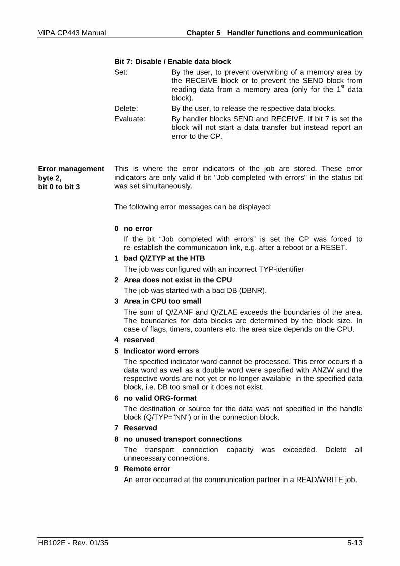
VIPA CP443 Manual Chapter 5 Handler functions and communication
HB102E - Rev. 01/35 5-13
Bit 7: Disable / Enable data blockSet: By the user, to prevent overwriting of a memory area by
the RECEIVE block or to prevent the SEND block fromreading data from a memory area (only for the 1st datablock).
Delete: By the user, to release the respective data blocks.Evaluate: By handler blocks SEND and RECEIVE. If bit 7 is set the
block will not start a data transfer but instead report anerror to the CP.
This is where the error indicators of the job are stored. These errorindicators are only valid if bit "Job completed with errors" in the status bitwas set simultaneously.
The following error messages can be displayed:
0 no errorIf the bit “Job completed with errors” is set the CP was forced tore-establish the communication link, e.g. after a reboot or a RESET.
1 bad Q/ZTYP at the HTBThe job was configured with an incorrect TYP-identifier
2 Area does not exist in the CPUThe job was started with a bad DB (DBNR).
3 Area in CPU too smallThe sum of Q/ZANF and Q/ZLAE exceeds the boundaries of the area.The boundaries for data blocks are determined by the block size. Incase of flags, timers, counters etc. the area size depends on the CPU.
4 reserved5 Indicator word errors
The specified indicator word cannot be processed. This error occurs if adata word as well as a double word were specified with ANZW and therespective words are not yet or no longer available in the specified datablock, i.e. DB too small or it does not exist.
6 no valid ORG-formatThe destination or source for the data was not specified in the handleblock (Q/TYP="NN") or in the connection block.
7 Reserved8 no unused transport connections
The transport connection capacity was exceeded. Delete allunnecessary connections.
9 Remote errorAn error occurred at the communication partner in a READ/WRITE job.
Error managementbyte 2,bit 0 to bit 3

Chapter 5 Handler functions and communication VIPA CP443 Manual
5-14 HB102E - Rev. 01/35
A Connection errorThe connection required for a job does not exist. This error is cleared assoon as a connection can be established. If all the connections of theCP have been are interrupted this indicates a defective module or buscable. The error can also be caused by bad configuration, e.g. incorrectaddressing.
B Handshake errorThis can be a system error or the data block size that was selected istoo high.
C Triggering errorAn incorrect handler block was used to trigger the job or the transferreddata block was too large.
D Termination after RESETThis is an operational message. For priority 1 and 2 the connection wasinterrupted and it is being re-established as soon as the communicationpartner is ready for a new connection. In case of priority 3 connectionsthe connection was cleared, it can be re-triggered.
E Job with bootstrap functionThis is an operational message. The job is a READ/WRITE-PASSIV andit can not be started from the CPU.
F Job does not existThe requested job was not configured on the CP. This error can occurwhen the SSNR/A-NR combination is entered incorrectly into thehandler block or if a connection block was not entered.
Bits 4 to 7 of byte 2 are reserved for future expansion.
The handler blocks (SEND, RECEIVE) deposit the quantity of data that hasalready been transferred for the respective job in the length word, i.e. forreceive jobs the quantity that has already been received, for transmit jobsthe quantity of data that has already been transmitted.Description: During the data exchange SEND, RECEIVE calculates
the "Length word" from:
actual quantity transferred + quantity alreadytransferred
Delete: By overwriting as well as with every new SEND,RECEIVE, FETCH.When the bit "Job completed without errors" or "Data-transfer/reception completed" is set the "length word"contains the up to date source or destination length.If the bit "Job completed with error" is set then the lengthword contains the quantity of data that was transferredbefore the error occurred.
Length wordbyte 3 ... byte 4

VIPA CP443 Manual Chapter 5 Handler functions and communication
HB102E - Rev. 01/35 5-15
The following section describes important status and error messages thatcan appear in the "indicator word". The representation makes use of"HEX"-patterns. The X means "undefined" or "irrelevant"; No. is the error-number.
Possible indicator words
Indicator word: X F X AError indicator ”F" shows that the respective job was not defined on theCP 443. Status indicator A inhibits the job (for SEND / FETCH andRECEIVE).
Indicator word: X A X AError indicator “A” shows that the connection for the communication taskwas not or not yet established. Status indicator "A" inhibits both SEND aswell as RECEIVE and FETCH.
Indicator word: X 0 X 8The connection was re-established (e.g. after a CP-reboot), SEND isenabled (communication task SEND).
Indicator word: X 0 X 9The connection was re-established, RECEIVE is enabled. (communicationtask RECEIVE).
Indicator word: X 0 2 4SEND was processed without errors, the data was transferred.
Indicator word: X 0 4 5RECEIVE was processed without errors, the data was transferred into thePLC.
Indicator word: X 0 X 2The SEND-, RECEIVE-, READ- or WRITE job is active. In case of SENDthe partner has not yet changed to RECEIVE mode. For RECEIVE thepartner has not yet issued the SEND.
Important statusand error indicatorsof the CP443

Chapter 5 Handler functions and communication VIPA CP443 Manual
5-16 HB102E - Rev. 01/35
The following table shows the most important status combinations of theindicator word :
Indicators during SEND/RECEIVE
Status Prio 2after a complete restart 0 A 0 Aafter a connection has been established X 0 X 9after a send job was triggered X 0 X 2
X 0 X 3RECEIVE handshake is meaningful and SEND jobactive
X 0 X 3
RECEIVE handshake is meaningful and SEND jobcompleted
X 0 X 5X 0 X 9
SEND completed without errors X 0 X 4X 0 X 5
SEND completed with errors X Nr. X 8X Nr. X 9
after a RESET X D X A
Due to the combination of send and receive operations in a single job no.SEND is managed by bit 1 "job active" and RECEIVE by bit 0 "handshakemeaningful" in the indicator word.
Note!You should define different data-areas for the indicator words SEND andRECEIVE so that the indicator word and the length word can be processeddifferently by the ALL blocks during data reception and transmission!
Indicators during READ/WRITE-AKTIV
Status Prio 2after a complete restart 0 A 0 Awhen connection is established X 0 0 8after a trigger X 0 X 2READ complete X 0 4 4WRITE complete X 0 2 4complete with errors X Nr X 8after RESET X D X A
Important indicatorword statuscombinations

VIPA CP443 Manual Chapter 5 Handler functions and communication
HB102E - Rev. 01/35 5-17
Length word
Length word Indicator word
15 0 Bit-No.31 16
The handler block (SEND, RECEIVE) deposits the data that that it hastransferred for the respective job in the length word ; received data inreceive jobs; transmitted data in send jobs.The entry in the "length word" is always in bytes and absolute.
Handler blocks (SEND, RECEIVE) deposit the quantity of data that hasalready been transferred for the respective job in the length word, i.e. forreceive jobs the quantity that has already been received, for transmit jobsthe quantity of data that has already been transmitted.
Description: During the data exchange SEND, RECEIVE calculatesthe "Length word" from:
actual quantity transferred + quantity alreadytransferred
Delete: By overwriting as well as with every new SEND,RECEIVE, FETCH.When the bit "Job completed without errors" or "Data-transfer/reception completed" is set the "length word"contains the up to date source or destination length.If the bit "Job completed with error" is set then the lengthword contains the quantity of data that was transferredbefore the error occurred.
Length wordbyte 3 and byte 4

Chapter 5 Handler functions and communication VIPA CP443 Manual
5-18 HB102E - Rev. 01/35
Structure of the configuration error byte - PAFE
The PAFE is set when a handler block has detected a configuration error.
7 6 5 4 3 2 1 0
Bit no.
0 = no error1 = error
not assigned
error number
Error numbers:0 no error1 bad ORG format2 area does not exist3 area too small4 reserved5 bad indicator word6 no source/destination parameter for SEND / RECEIVE ALL7 interface does not exist8 interface faulty9 interface overloadA not usedB illegal job number ANRC interface does not acknowledge or not enabledD not assignedE not assignedF not assigned
PAFEconfigurationerror byte

VIPA CP443 Manual Chapter 5 Handler functions and communication
HB102E - Rev. 01/35 5-19
FC 120 - SEND
The SEND block is used to initiate a job for a CP with or without datatransfer.
SSNR
A_NR
QTYP
DBNR
QANF
QLAE
ANZW PAFE
SEND
FC 120
SSNR: Interface number, number of the logical interfaceA_NR: the job that must be initiated at the interface, i.e. start
transmission of a messageQTYP: Type of data source where the data originatesDBNR: Number of the data block for QTYP XX, RW (read/write), DBQANF: "Relative start address" of the data SourceQLAE: Source data quantity (in bytes or words)ANZW: Address of the indicator word (double word) where the
progress of the started job is being displayedPAFE: Error indicator for configuration errors
Parameters

Chapter 5 Handler functions and communication VIPA CP443 Manual
5-20 HB102E - Rev. 01/35
Description of the SEND-ALL-functionFor the SEND-ALL function (job number 0) the block only requiresparameters: SSNR, A-NR = 0, ANZW and PAFE.All other parameters are irrelevant for this job. For the SEND-ALL-functionthe CP must supply the address of the indicator word, the specification ofthe data type, the quantity and the start address of the data in thecommunication area.In the indicator word, that is assigned to the relevant job the bits for"ENABLE/DISABLE", "Data transfer completed" as well as "Data-transferactive" can be tested or modified. The quantity of data for a job is displayedby SEND-ALL in the data or flag word following the ANZW.
The block-indicator-word (indicator word, that was configured in theSEND-ALL-block) contains the current job number (0 means dummy run).The quantity of data that must be transferred for a job is displayed bySEND-ALL in the data word that follows after the indicator word.The SEND-ALL-function (i.e. the call to the send-block including the ALL-configuration) must be called at least once within a PLC-cycle for everyinterface when:
• the CP can request data independently from a PLC.
• a CP-job is initiated by a SEND-DIREKT, but the CP only requests thedata for this job via “background communications” from the PLC.
• the quantity of data that is transferred to the CP with SEND-DIREKT islarger than the specified block size.
Description of the SEND-DIREKT functionThe block required the following parameters for the "DIREKT"-function:
• interface number
• job number >< 0
• specification of the indicator word
• specification of the error byte "PAFE"
• source type with DBNR
• source start address
• the quantity of source data.
Normally the "SEND-DIREKT"-block is called from the cyclic portion of theapplication program. It is possible to include the block in the interrupt orwatchdog section of the program, but the indicator word (ANZW) can notbe updated cyclically in this case (it must be transferred by means of theCONTROL-block).For the data transfer and for the activation of the send trigger theconnection to the CP is only established when:
• FC was supplied with VKE "1".
• the CP has enabled the job. (Bit "Job active" in ANZW =0).
SEND-ALL
SEND-DIRECT

VIPA CP443 Manual Chapter 5 Handler functions and communication
HB102E - Rev. 01/35 5-21
Only the indicator word is updated when the block is idle (when VKE "0" istransferred).If the QTYP-parameter contains identifier "NN" the source-parameters ofthe CP are used. If these parameters are also not available then the job isterminated with an error-message.
If the CP can obtain on the data directly the SEND-block transfers therequested data in one process into the CP. However, if the CP signals thatit only requires the parameters of the job or if the quantity of the data thatmust be transferred is too high only the parameters (QTYP/QLAE etc.) orthe parameters of the first data block are transferred to the CP. The data orthe subsequent blocks for these jobs are requested by the CP by means ofthe SEND ALL function from the PLC. For this purpose it is necessary thatthe SEND ALL block be called at least once in every PLC-cycle.The operator interface is same for all "triggering types", only the time of thedata-transfer is postponed by at least one cycle for the last casesmentioned above.
Description of the WRITE-functionIndirectly specified source and destination parameters are transferred tothe CP during configuration with QTYP = "RW" using "SEND". In this casethe destination parameters together with the user data (that wererequested by means of SEND ALL) is transmitted to the communicationpartner ("WRITE"-function).
WRITE function

Chapter 5 Handler functions and communication VIPA CP443 Manual
5-22 HB102E - Rev. 01/35
FC 121 - RECEIVE
The RECEIVE-block requests the status of or starts a RECEIVE-job on aCP, with or without data transfer.
SSNR
A_NR
QTYP
DBNR
QANF
QLAE
ANZW PAFE
FC 121
RECEIVE
SSNR: Interface number, number of the logical interfaceA_NR: RECEIVE-job of the interface, interrogation after a message
was received along with the data transferQTYP: The type of data destination where the data should be stored.DBNR: Number of the DB for QTYP XX, DBQANF: "Relative start address" of the data destinationQLAE: Quantity of data that must be transferredANZW: Address of the indicator word (double word) where the
completion of the job is displayedPAFE: Error indicator for configuration errors
Parameter
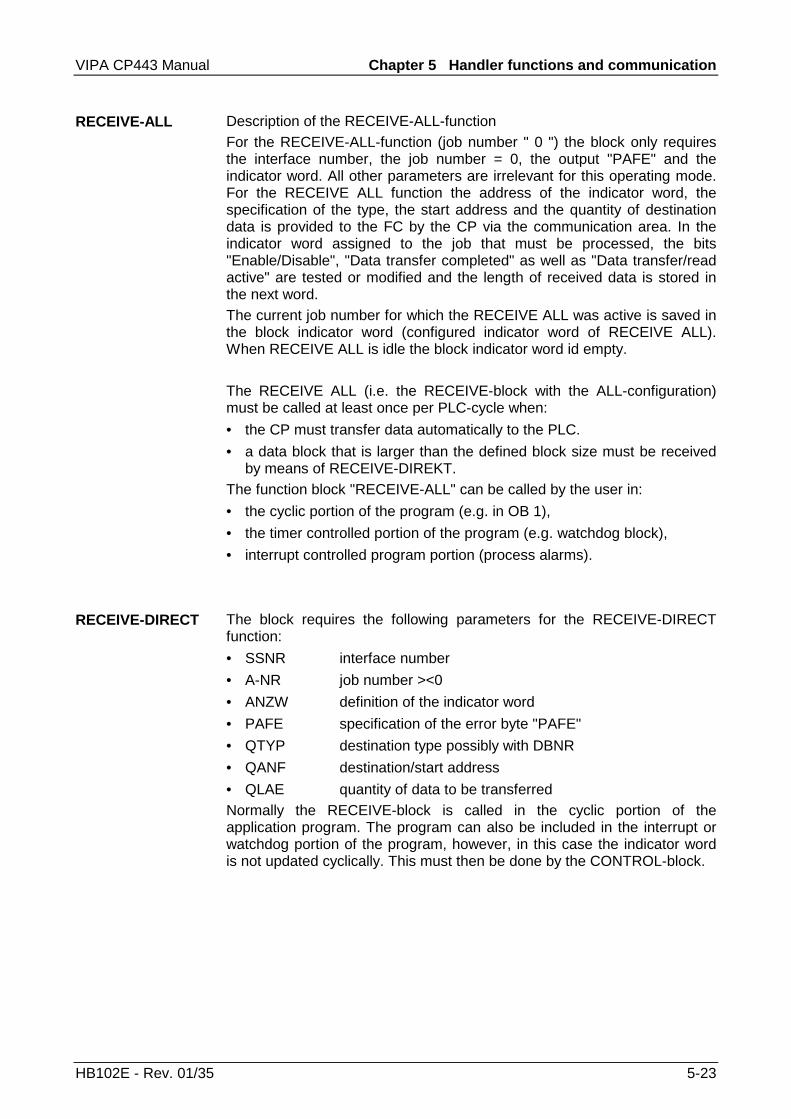
VIPA CP443 Manual Chapter 5 Handler functions and communication
HB102E - Rev. 01/35 5-23
Description of the RECEIVE-ALL-functionFor the RECEIVE-ALL-function (job number " 0 ") the block only requiresthe interface number, the job number = 0, the output "PAFE" and theindicator word. All other parameters are irrelevant for this operating mode.For the RECEIVE ALL function the address of the indicator word, thespecification of the type, the start address and the quantity of destinationdata is provided to the FC by the CP via the communication area. In theindicator word assigned to the job that must be processed, the bits"Enable/Disable", "Data transfer completed" as well as "Data transfer/readactive" are tested or modified and the length of received data is stored inthe next word.The current job number for which the RECEIVE ALL was active is saved inthe block indicator word (configured indicator word of RECEIVE ALL).When RECEIVE ALL is idle the block indicator word id empty.
The RECEIVE ALL (i.e. the RECEIVE-block with the ALL-configuration)must be called at least once per PLC-cycle when:
• the CP must transfer data automatically to the PLC.
• a data block that is larger than the defined block size must be receivedby means of RECEIVE-DIREKT.
The function block "RECEIVE-ALL" can be called by the user in:
• the cyclic portion of the program (e.g. in OB 1),
• the timer controlled portion of the program (e.g. watchdog block),
• interrupt controlled program portion (process alarms).
The block requires the following parameters for the RECEIVE-DIRECTfunction:
• SSNR interface number
• A-NR job number ><0
• ANZW definition of the indicator word
• PAFE specification of the error byte "PAFE"
• QTYP destination type possibly with DBNR
• QANF destination/start address
• QLAE quantity of data to be transferredNormally the RECEIVE-block is called in the cyclic portion of theapplication program. The program can also be included in the interrupt orwatchdog portion of the program, however, in this case the indicator wordis not updated cyclically. This must then be done by the CONTROL-block.
RECEIVE-ALL
RECEIVE-DIRECT

Chapter 5 Handler functions and communication VIPA CP443 Manual
5-24 HB102E - Rev. 01/35
The handshaking traffic with the CP (i.e. the triggering of a job) is onlyaccepted by the RECEIVE block in the "DIREKT"-function when:
• VKE "1" is transferred to the FC and
• the CP has enabled the job. (bit "Handshake meaningful” = 1).
Only the indicator word will be updated when the block is “idle”.The RECEIVE-(DIRECT)-block reacts differently, depending on the type ofinput and on the CP-reaction:
• If the indicator "NN" is entered into the QTYP-parameter the blockexpects the destination parameters (type, start, length of destinationdata-block) from the CP. If the CP supplied a parameter set and theRECEIVE-block has already been provided with destination parameters,(QTYP><NN) then the parameters of the block are preferred over theones supplied by the CP.
• Large quantities of data can only be transferred in blocks. For thispurpose this set of linked blocks must be transferred into the PLC bymeans of the RECEIVE-ALL. The call to RECEIVE-ALL must occur atleast once per cycle (for every CP-interface) when it is necessary thatlarge quantities of data are exchanged with a CP. It is also necessary toinclude the RECEIVE-ALL in the cycle when the CP uses the RECEIVE-DIREKT only to release a received message and to transfer the data viathe "background communication routine" into the PLC.
• In the RECEIVE the configuration with QTYP = "RW" is illegal.

VIPA CP443 Manual Chapter 5 Handler functions and communication
HB102E - Rev. 01/35 5-25
FC 122 - FETCH
The FETCH-block issues a fetch job to a partner station.The FETCH-job defines the source and destination for the data and this isthen transferred to the partner station.For the VIPA CPU 24x the source and destination is specified indirectly in aDB. The respective number for the FETCH is entered into DBNR. Theidentification of the indirect specification is done by means of ZTYP=RW.The partner station prepares the data and returns this via SEND-ALL to therequesting station. The data is received by means of RECEIVE-ALL andare saved on the destination.The update of the indicator word is handled by the FETCH or theCONTROL.The handshaking exchange for triggering the FETCH is only started when
• the block was supplied with VKE "1"
• the function was released in the respective CP-indicator word (jobactive = 0).
SSNR
A_NR
ZTYP
DBNR
ZANF
ZLAE
ANZW PAFE
FC 122
FETCH
SSNR: Interface number, number of the logical interfaceA_NR: FETCH- or READ-job that must be startedZTYP: Type of data destination (DB, flag, etc.)DBNR: Number of the DB for ZTYP XX, RW, DBZANF: "Relative start address" of the data destinationZLAE: Quantity of data that must be transferred.ANZW: Indicator word (address of indicator word).PAFE: Error indicator for configuration errors.
Note!Detailed information on the indirect configuration is available on page 5-7.
Parameter

Chapter 5 Handler functions and communication VIPA CP443 Manual
5-26 HB102E - Rev. 01/35
FC 123 - CONTROL
The purpose of the CONTROL-block is as follows:
• to update the indicator word (job number >< 0 was configured).
• check whether a certain job of the CP is “active” at the moment, e.g.check after a message was received (job no. >< 0 was configured).
• check which job is currently being processed by the CP (job no. = 0 wasconfigured).
The CONTROL block does not enter into handshaking traffic with the CP, itonly transfers the indicators from the "job-status" into the configuredindicator word. This block does not depend on the status of the VKE shouldbe called in the cyclic portion of the program.
The indicator word for the CONTROL-DIRECT function (parameterA-NR><0) has the same contents and it is processed in the same manneras all other "handler blocks" (see description of block parameter ANZW).
If the "job number" parameter is provided with a 0 the CONTROL-command transfers the contents of the job-status-cell 0 to the LOW-portionof the indicator word. The CP stores the number of the current job (that isthe job, that is being processed right now, e.g. the job number of amessage) into the job-status-cell 0.
SSNR
A_NR
ANZW PAFE
FC 123
CONTROL
SSNR: Interface numberA_NR: Job on the CP that must be monitored, e.g. test, whether
the started job was completed with or without errors.ANZW: Indicator word returning the result of the test to the user.PAFE: Error byte when configuration errors are encountered.
Parameter

VIPA CP443 Manual Chapter 5 Handler functions and communication
HB102E - Rev. 01/35 5-27
FC 124 - RESET
The RESET ALL-function is selected by means of job number 0. Thisresets all the jobs of this logical interface; for instance, it deletes all jobdata and breaks terminates all active jobs. A "direct" function (jobnumber><0) only resets the specified job on the logical interface.The block depends on the status of the VKE and can be called from thecyclic, the timer controlled or the alarm controlled portion of the program.
SSNR
A_NR PAFE
FC 124
RESET
SSNR: Interface numberA-NR: Number of the job that must be resetPAFE: Error byte when configuration errors are encountered.
The block recognizes the following operating modes:
• RESET ALL
• RESET DIREKT.
Parameter
Operating modes

Chapter 5 Handler functions and communication VIPA CP443 Manual
5-28 HB102E - Rev. 01/35
FC 125 - SYNCHRON
This block initiates the synchronization between the PLC and the CP andfor this reason it must be called during the start-up OBs. At the same timethe transfer area of the interface is cleared and set to the default and theblock-size between CP and PLC is negotiated.
SSNR
BLGR PAFE
FC 125
SYNCHRON
SSNR: Interface numberBLGR: Block sizePAFE: Parameter error
The following block sizes can be selected:
Value Block size
0 The block uses default parameters(set to 512 byte on the CP443)
1 16 byte blocks2 32 byte blocks3 64 byte blocks4 128 byte blocks5 256 byte blocks6 512 byte blocks
>6 and < 255 is treated as 0.
Parameter
Block sizes

VIPA CP443 Manual Chapter 5 Handler functions and communication
HB102E - Rev. 01/35 5-29
Communication links to foreign systems
The organization-format is the abbreviated description of a data-source ora data-destination in a PLC environment. The following table lists theavailable ORG-formats.In the case of READ and WRITE the ORG-block is optional.The ERW-identifier is used for the addressing of data blocks. In this casethe data block number is entered into this identifier. The start address andquantity provide the address for the memory area and they are stored inHIGH-/LOW- format (Motorola-formatted addresses)
Description Type RangeORG identifier BYTE 1..xERW identifier BYTE 1..255Start address HILOWORD 0..yQuantity HILOWORD 1..z
The following table contains a list of available ORG formats. The "length"must not be entered as -1 (FFFFh).
ORG identifier 01h-04hCPU area DB MBORG identifier 01h 02hDescription Source/destination data
from/into data block inmain memory.
source/destination datafrom/into flag area.
DBNR
valid range:
DB from where the sourcedata is retrieved or towhere the destination datais transferred.
1...255
irrelevant
Start addressSignificance
valid range:
DW-No. from where thedata is retrieved or wheredata is saved.
1...2047
MB- No. from where thedata is retrieved or wheredata is saved.
0...255
QuantitySignificance
valid range:
Length of thesource/destination data -block in words.
1...2048
Length of thesource/destination data -block in words.
1...256
ORG format

Chapter 5 Handler functions and communication VIPA CP443 Manual
5-30 HB102E - Rev. 01/35
For every READ and WRITE the CP generates PLC headers for requestmessages and for acknowledgment messages. Normally the length ofthese headers is 16 bytes and they have the following structure:
Structure of PLCheader
for WRITE Acknowledgment message
System identifier ="S"="5"
Length of header =16d Ident.OP-code =01 Length of OP-code =03 OP-Code =04 Ack. block =0Fh Length of Ack-block =03 Error No. =Nr. Dummy block =FFh Length of dummy bl. =07
not used
Request message
System identifier ="S"="5"
Length of header =16d Ident.OP-code =01 Length of OP-code =03 OP-Code =03 ORG-block =03 Length of ORG-block =08ORG identifier DBNR Start address H
L Length H
L Dummy block =FFh Length of dummy bl. =02
Up to 64K data but only iferror no.=0
Acknowledgment message
System identifier ="S"="5"
Length of header =16d Ident.OP-code =01 Length of OP-code =03 OP-Code =06 Ack. block =0Fh Length of Ack-block =03 Error No. =Nr. Dummy block =FFh Length Dummy block =07
not used
Up to 64K data but only iferror no.=0
for READ Request message
System identifier ="S"="5"
Length of header =16d Ident.OP-code =01 Length of OP-code =03 OP-Code =05 ORG-block =03 Length of ORG-block =08ORG identifier DBNR Start address H
L Length H
L Dummy block =FFh Length of dummy block=02

VIPA CP443 Manual Chapter 5 Handler functions and communication
HB102E - Rev. 01/35 5-31
TRADA stands for Transparent Data exchange. A transparent dataexchange can transfer application data with varying block lengths. A 16-byte header that defines the length of the application data precedes theapplication data.With TRADA you can enter a default length into the PLC applicationprogram.If you enter -1 as the length into the RECEIVE-FC (parameter: ZLAE) youare defining a variable length (default length) for the application data. Withthe default length the actual length of the data is retrieved from therespective TRADA header.
With the TRADA functionality the following header will precede a SEND joband it is analyzed by the RECEIVE function.
→ Length of the application data
The length filed contains the number of bytes in a data block.If you are synchronizing with a block size of 6 (512 bytes) the length isentered in words.
SEND / RECEIVEof the type TRADA
SEND of type TRADAOP-Code = 07
System identifier ="S"="5"
Length of header =16d Ident.OP-code =01 Length of OP-code =03 OP-Code =07 ORG-block =03 Length of ORG-block =08ORG identifier DBNR (irrelevant) Start address H
L Length H
L Dummy block =FFh Length of dummy block
=02Up to 64K data but only if
error no.=0
Length

Chapter 5 Handler functions and communication VIPA CP443 Manual
5-32 HB102E - Rev. 01/35

VIPA CP443 Manual Index
HB102E - Rev. 01/35 A-1
Appendix
A IndexA
A_NR ......................................5-4Access control ........................3-3ANZW .....................................5-5
Length word ............................ 5-17
Status...................................... 5-16
Structure ................................... 5-9
Applications ............................1-5
B
BLGR......................................5-5Block size................................4-9Broadcast address ..................3-4
C
CompactFlash.........................2-5Configuration ..........................4-3
Alternate CP ............................. 4-5
CP-side ..................................... 4-3
error byte ................................ 5-18
Example.................................. 4-10
Initial configuration.................. 4-25
on the PLC-side ........................ 4-5
via Ethernet............................. 4-26
Construction............................2-4CP443 applications .................4-1
D
DBNR......................................5-4Default length.................2-9; 5-31DVI-socket ..............................2-8
E
EthernetInterface.................................... 2-6
Mini-hub .................................... 2-7
Standards ................................. 3-7
H
Handler functions ............ 4-8; 5-1Error indicator ANZW ............... 5-9
FC 120 SEND......................... 5-19
FC 121 RECEIVE................... 5-22
FC 122 FETCH....................... 5-25
FC 123 CONTROL................. 5-26
FC 124 RESET....................... 5-27
FC 125 SYNCHRON .............. 5-28
Overview................................... 4-8
Parameters............................... 5-3
Hardware description ..............2-1Hub .........................................3-2
I
Initial configuration ................4-25Installation.............................4-24IP-address...............................3-4
K
Keyboard port .........................2-7
L
LEDs .......................................2-5Length word ..........................5-17
M
Monitor interface .....................2-8Mouse port ..............................2-7
N
Network...................................3-2Network planning ....................3-5Network requirements .............3-6Null-modem cable ...................2-6
O
Operation ................................1-6Ordering information ...............1-1ORG Organization format .....5-29

Index VIPA CP443 Manual
A-2 HB102E - Rev. 01/35
P
PAFE ....................................5-18PG functions ..................4-2; 4-27
Differences to Siemens .......... 4-27
PLC header...........................5-30PLC-Programming ..................4-8Principles ................................1-1Properties ...............................2-3
Q
QANF/ZANF ...........................5-4QLAE/ZLAE ............................5-5QTYP/ZTYP............................5-4
R
RJ45 socket ............................2-6RS232C interface....................2-6
cable ......................................... 2-6
S
Safety information ...................1-2SSNR......................................5-4STATUS
Indicator.................................... 5-9
Switch Hub..............................3-2Synchronization.......................4-9System overview .....................2-2System properties ...................2-9
T
TCP/IP ....................................3-3Technical data.......................2-10TRADA..................................5-31Twisted Pair ............................3-2
Restrictions............................... 3-6
Twisted Pair networks .............3-1
V
Versions ..................................1-4
M.Stich


![Company Profiles Vipa / Vipa Polimeri Page 1/18 profile Vipa... · Company Profiles Vipa / Vipa Polimeri Page 2/18 VIPA S.r.l. [beginnings]Vipa is a leading company in the field of](https://img.dokumen.tips/doc/110x75/5f5cfa7c6cc46b644e27ef7b/company-profiles-vipa-vipa-polimeri-page-118-profile-vipa-company-profiles.jpg)