Embed Size (px)
Citation preview
Manual
VIPA CPU 24x
Order no.: VIPA HB99E_CPU Rev. 08/32

Lerrzeichen
Manual VIPA CPU 24x About this manual
Subject to change to cater for technical progress.
The information contained in this manual is supplied without warranties. Information is subject to change without notice. © Copyright 2008 VIPA, Gesellschaft für Visualisierung und Prozess-
automatisierung mbH Ohmstraße 4, D-91074 Herzogenaurach,
Tel.: +49 (91 32) 744 -0 Fax.: +49 (91 32) 744-144 E-mail: [email protected] http://www.vipa.de Hotline: +49 (91 32) 744-114 All rights reserved
The contents of this manual was carefully examined to ensure that it conforms with the described hardware and software. However, discrepancies can not be avoided. The specifications in this manual are examined regularly and corrections will be included in subsequent editions. We gratefully accept suggestions for improvement.
VIPA
is a registered trademark of VIPA Gesellschaft für Visualisierung und Prozessautomatisierung mbH
SIMATIC is a registered trademark of Siemens AG.
STEP5 is a registered trademark of Siemens AG.
Any other trade marks referred to in the text are the trade marks of the respective owner and we acknowledge their registration.
Disclaimer of liability
Trade marks
About this manual Manual VIPA CPU 24x
Subject to change to cater for technical progress.
About this manual
This manual describes the operation of the CPU 24x in the VIPA System 200V. The text provides details on the hardware, the programming and the functions integrated into the unit.
Chapter 1: Principles This introduction includes recommendations on the handling of the module as well as information about applications and implementations for CPU modules. You can also read certain details about the mode of operation of the CPU 24x.
Chapter 2: Hardware description Different versions of the CPU are available (CPU 24x, CPU 24x DP, CPU 24x NET). This chapter describes these versions in greater detail. In addition to the hardware description the chapter also includes instructions on commissioning and applications for the memory modules. The chapter is concluded by a summary of the integrated FBs and OBs and the technical data.
Chapter 3: CPU 24x applications using I/O modules This chapter describes applications for the CPU 24x, CPU 24x DP, CPU 24x NET that include the peripheral modules of the System 200V.
Chapter 4: CPU 24x2BT10 NET deployment Applications, project design, functional description and programming of the CPU 24x2BT10 NET.
Chapter 5: CPU 24x2BT01 NET deployment Applications, project design, functional description and programming of the CPU 24x2BT01 NET.
Chapter 6: CPU 24x DP deployment Applications, configuration, description and parameter definition for the CPU 24x DP under Profibus.
Overview
Manual VIPA CPU 24x About this manual
Subject to change to cater for technical progress.
Chapter 7: Operating modes Contains a description of the operating states Stop, Run, and start-up. This chapter also contains an explanation of the cyclic operation, the timer dependent and the alarm controlled operation of the program.
Chapter 8: Introduction to the programming language This chapter contains a description of the programming of automation applications. The explanation shows how programs are created and the blocks that you can use to structure a program. You are also provided with a summary of the different types of numeric notation that are available in the programming language.
Chapter 9: Operations Contains a more detailed description of the instruction set. Primary operations, complementary operations and system operations are explained by means of examples.
Chapter 10: Integrated blocks This chapter contains a description of the integrated FBs, the organization blocks and default DB 1 (for the configuration of internal functions).
Chapter 11: Clock functions This chapter describes the structure and the configuration of the integrated clock. Currently an integrated clock is available on CPU-types CPU 243 and CPU 244.
Chapter 12: Alarm- and timer controlled processing Here you can obtain information on the program execution and/or the interruption of the cyclic program operation of the CPU 24x.

About this manual Manual VIPA CPU 24x
Subject to change to cater for technical progress.
Manual VIPA CPU 24x Contents
HB99E - CPU - Rev. 08/32 i
Contents
User considerations ................................................................................. 1 Safety information .................................................................................... 2 Chapter 1 Basics .............................................................................. 1-1
Safety information for users.................................................................. 1-2 General ................................................................................................ 1-3 Applications.......................................................................................... 1-4 Features............................................................................................... 1-5 Versions ............................................................................................... 1-6 Operation of a CPU .............................................................................. 1-7 CPU 24x programs............................................................................... 1-8 CPU 24x operands ............................................................................... 1-8
Chapter 2 Hardware description...................................................... 2-1 System overview .................................................................................. 2-2 Construction ......................................................................................... 2-6 Components......................................................................................... 2-8 Block diagram .................................................................................... 2-16 Commissioning................................................................................... 2-17 Booting behavior ................................................................................ 2-18 OVERALL RESET and reboot ............................................................ 2-19 Loading and saving an application program ....................................... 2-20 Test function STATUS/STATUS VAR and STEUERN........................ 2-22 MMC memory module ........................................................................ 2-24 Memory areas .................................................................................... 2-25 USTACK - output of system data by means of the PG........................ 2-27 Significance of the USTACK indicators............................................... 2-32 Integrated FBs and OBs ..................................................................... 2-34 Technical data.................................................................................... 2-36
Chapter 3 CPU 24x deployment using I/O modules....................... 3-1 Applications in conjunction with I/O modules ........................................ 3-2 Automatic assignment of peripheral addresses .................................... 3-3 Manual assignment of peripheral addresses ........................................ 3-5 Configuration of peripheral modules ..................................................... 3-6
Chapter 4 CPU 24x-2BT10 deployment........................................... 4-1 Industrial Ethernet in automation .......................................................... 4-2 ISO/OSI reference model ..................................................................... 4-3 Principles.............................................................................................. 4-6 Protocols .............................................................................................. 4-7 IP address and subnet........................................................................ 4-10 Network planning................................................................................ 4-12 Communication possibilities of the CP................................................ 4-14 Programming Communication Connections........................................ 4-16 SEND/RECEIVE with PLC program ................................................... 4-23 Coupling to other systems .................................................................. 4-27 NCM diagnostic – Help for error diagnostic ........................................ 4-30
Contents Manual VIPA CPU 24x
ii HB99E - CPU - Rev. 08/32
Chapter 5 CPU 24x-2BT01 deployment........................................... 5-1 Principles.............................................................................................. 5-2 Network planning.................................................................................. 5-7 Standards and norms ........................................................................... 5-9 Ethernet and IP-addresses................................................................. 5-10 Configuration of the CPU 24x NET..................................................... 5-12 Examples for the configuration ........................................................... 5-16 Boot behavior ..................................................................................... 5-29 System properties of the CPU 24x NET ............................................. 5-30 Communication links to foreign systems............................................. 5-32 Status and error indicators ................................................................. 5-36 Test program for TCP/IP connections................................................. 5-44
Chapter 6 CPU 24x DP deployment................................................. 6-1 Principles.............................................................................................. 6-2 CPU 24x DP configuration.................................................................... 6-6 Modifying the default addressing by means of DB 1 ............................. 6-9 Access to parameter data................................................................... 6-12 Configuration of directly installed I/O modules.................................... 6-13 Diagnostic functions of the CPU 24x DP............................................. 6-14 Status messages, internal to CPU...................................................... 6-17 Installation guidelines ......................................................................... 6-19 Commissioning................................................................................... 6-24 The application of the diagnostic LEDs............................................... 6-27 Example ............................................................................................. 6-28
Chapter 7 Operating modes............................................................. 7-1 Introduction and outline ........................................................................ 7-2 Program processing levels ................................................................... 7-3 Operating mode STOP......................................................................... 7-6 Operating mode START-UP................................................................. 7-8 Operating mode RUN......................................................................... 7-11 Program flow ...................................................................................... 7-12
Chapter 8 Introduction to the programming language .................. 8-1 Programming procedure....................................................................... 8-2 Creating a program .............................................................................. 8-4 Program structure................................................................................. 8-8 Block types........................................................................................... 8-9 Program execution ............................................................................. 8-22 Processing of blocks .......................................................................... 8-32 Numeric representation ...................................................................... 8-34 Troubleshooting the program.............................................................. 8-35
Chapter 9 Operations....................................................................... 9-1 Introduction .......................................................................................... 9-2 Primary operations ............................................................................... 9-3 Supplementary operations.................................................................. 9-40 System operations.............................................................................. 9-66 Setting of flags.................................................................................... 9-76 Programming examples...................................................................... 9-79

Manual VIPA CPU 24x Contents
HB99E - CPU - Rev. 08/32 iii
Chapter 10 Integrated Blocks.......................................................... 10-1 Integrated functions............................................................................ 10-2 FB 238 - COMPR (compress)............................................................. 10-3 FB 239 - DELETE............................................................................... 10-4 FB 240 - COD:B4 (code conversion BCD/DUAL) ............................... 10-5 FB 241 - COD:16 (code conversion DUAL/BCD)................................ 10-6 FB 242 - MUL:16 (Multiplier)............................................................... 10-7 FB 243 - DIV:16 (Divider) ................................................................... 10-8 FB 250 - RLG:AE (Read an normalize an analog value)..................... 10-9 FB 251 - RLG:AA (Analog value output) ........................................... 10-12 Example of analog data processing.................................................. 10-14 Integrated handler blocks ................................................................. 10-17 The handler block parameters .......................................................... 10-18 Parameter description of the handler blocks..................................... 10-19 Configuration of SSNR, A-NR, ANZW and BLGR............................. 10-21 Indirect configuration of source- and destination identifiers .............. 10-24 Table of the possible QTYP/ZTYP parameters................................. 10-25 Indicator word structure .................................................................... 10-27 Status and error indicator in the indicator word................................. 10-28 Indicator word................................................................................... 10-29 Length - Word .................................................................................. 10-35 Structure of the configuration error indicator byte ............................. 10-36 Adjustable block size........................................................................ 10-37 FB 244 - SEND................................................................................. 10-38 FB 245 - RECEIVE........................................................................... 10-41 FB 246 - FETCH............................................................................... 10-44 FB 247 - CONTROL ......................................................................... 10-45 FB 248 - RESET............................................................................... 10-46 FB 249 - SYCHRON......................................................................... 10-47 Integrated special organization blocks.............................................. 10-48 OB 31 - Cycle time triggering............................................................ 10-49 OB 160 - Variable timing loop........................................................... 10-50 OB 251 - PID control algorithm......................................................... 10-51 Integrated block DB 1....................................................................... 10-61
Chapter 11 Clock functions ............................................................. 11-1 General .............................................................................................. 11-2 Configuration of the integrated clock .................................................. 11-3 Structure of the clock data area.......................................................... 11-7 Structure of the status word.............................................................. 11-10 Setting and reading the clock ........................................................... 11-12 Alarm functions................................................................................. 11-19 Operating time counter ..................................................................... 11-22
Chapter 12 Alarm and timer controlled processing....................... 12-1 Programming of alarm blocks ............................................................. 12-2 Timer controlled program execution ................................................... 12-4 Elapsed time controlled program execution ........................................ 12-6 Priority and response time.................................................................. 12-7 Alarm diagnostic data....................................................................... 12-11

Contents Manual VIPA CPU 24x
iv HB99E - CPU - Rev. 08/32
Appendix ..........................................................................................A-1 Statement list .......................................................................................A-1 Object code ..........................................................................................B-1 Index ................................................................................................... C-1
Manual VIPA CPU 24x User considerations
HB99E - CPU - Rev. 08/32 1
User considerations
This manual describes the CPU 24x as well as all the versions of the product. It contains a description of the construction, project implementation and the application of the product. The CPU 24x is compatible with all System-200V components of VIPA. The manual is targeted at users who have a background in automation technology and PLC-programming. The current manual consists of chapters. Every chapter consists of a self-contained description of a specific topic. This manual provides the following guides: • An overall table of contents at the beginning of the manual • An overview of the topics for every chapter • An index at the end of the manual. The manual is available in: • printed form, on paper • in electronic form as PDF-file (Adobe Acrobat Reader) Important passages in the text are highlighted by following icons and headings: Danger! Immediate or likely danger. Personal injury is possible. Attention! Damages to property is likely if these warnings are not heeded. Note! Supplementary information and useful tips
Objective and contents
Target audience
Structure of the manual
Guide to the document
Availability
Icons Headings
Safety information Manual VIPA CPU 24x
2 HB99E - CPU - Rev. 08/32
Safety information
The CPU 24x is constructed and produced for • all VIPA System-200V components • communication and process control • general control and automation applications • industrial applications • operation within the environmental conditions specified in the technical
data • installation into a cubicle
Danger! This device is not certified for applications in • in explosive environments (EX-zone)
The manual must be available to all personnel in the • project design department • installation department • commissioning • operation
The following conditions must be met before using or commissioning the components described in this manual: • Modification to the process control system should only be carried out
when the system has been disconnected from power! • Installation and modifications only by properly trained personnel • The national rules and regulations of the respective country must be
satisfied (installation, safety, EMC ...)
National rules and regulations apply to the disposal of the unit!
Applications conforming with specifications
Documentation
Disposal
Manual VIPA CPU 24x Chapter 1 Basics
HB99E - CPU - Rev. 08/32 1-1
Chapter 1 Basics
This introduction contains references on the handling and applications of the CPU-modules. It also provides certain suggestions on the approach you can use when programming the module and the CPU specifications that are important in this respect.
Topic Page Chapter 1 Basics .............................................................................. 1-1
Safety information for users.................................................................. 1-2 General ................................................................................................ 1-3 Applications.......................................................................................... 1-4 Features............................................................................................... 1-5 Versions ............................................................................................... 1-6 Operation of a CPU.............................................................................. 1-7 CPU 24x programs............................................................................... 1-8 CPU 24x operands ............................................................................... 1-8
Outline
Contents
Chapter 1 Basics Manual VIPA CPU 24x
1-2 HB99E - CPU - Rev. 08/32
Safety information for users
VIPA-modules make use of highly integrated components in MOS-technology. These components are extremely sensitive to over-voltages that can occur during electrostatic discharges. The following symbol is attached to modules that can be destroyed by electrostatic discharges:
The symbol is located on the module, the module rack or on packing material and it indicates the presence of electrostatic sensitive equipment. It is possible that electrostatic sensitive equipment is destroyed by energies and voltages that are far less than the human threshold of perception. These voltages can occur where persons do not discharge themselves before handling electrostatic sensitive modules and they can damage components thereby causing the module to become inoperable or unusable. Modules that have been damaged by electrostatic discharge are usually not detected immediately. The respective failure can only become apparent after a period of operation. Components damaged by electrostatic discharges can fail after a temperature change, mechanical shock or changes in the electrical load. Only the consistent implementation of protective devices and meticulous attention to the applicable rules and regulations for handling the respective equipment can prevent failures of electrostatic sensitive modules.
Handling of electrostatic sensitive modules
Manual VIPA CPU 24x Chapter 1 Basics
HB99E - CPU - Rev. 08/32 1-3
Modules must be shipped in the original packing material.
When you are conducting measurements on electrostatic sensitive modules you should take the following precautions: • Floating instruments must be discharged before use. • Instruments must be grounded. You should only use soldering irons with grounded tips when you are making modifications on electrostatic sensitive modules.
Attention! Personnel and instruments should be grounded when working on electrostatic sensitive modules.
General
The instruction set of the CPU 24x is compatible with the STEP®5 programming language of Siemens and provides integrated FBs and OBs.
System-200V-moduled are configured via DB1 using the WinNCS configuration software supplied by VIPA.
The CPU 24x has an integrated power supply that requires 24V DC via the front panel. The power supply is protected against reverse polarity and short circuits.
Shipping of electrostatic sensitive modules
Measurements and alterations on electrostatic sensitive modules
Compatible instruction set
Configuration via DB1
Integrated power supply
Chapter 1 Basics Manual VIPA CPU 24x
1-4 HB99E - CPU - Rev. 08/32
Applications
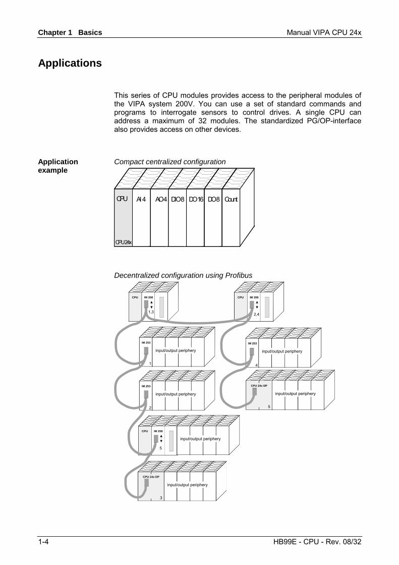
This series of CPU modules provides access to the peripheral modules of the VIPA system 200V. You can use a set of standard commands and programs to interrogate sensors to control drives. A single CPU can address a maximum of 32 modules. The standardized PG/OP-interface also provides access on other devices.
Compact centralized configuration
CPU AI 4 AO 4 DIO 8 DO 16
CPU 24x
DO 8 Count
Decentralized configuration using Profibus
3
input/output periphery
CPU 24x DP
5
input/output periphery
CPU 24x DP
CPU IM 208
5
CPU IM 208
1,3
IM 253
1
input/output periphery
IM 253
2
input/output periphery
CPU IM 208
2,4
IM 253
4
input/output periphery
input/output periphery
Application example
Manual VIPA CPU 24x Chapter 1 Basics
HB99E - CPU - Rev. 08/32 1-5
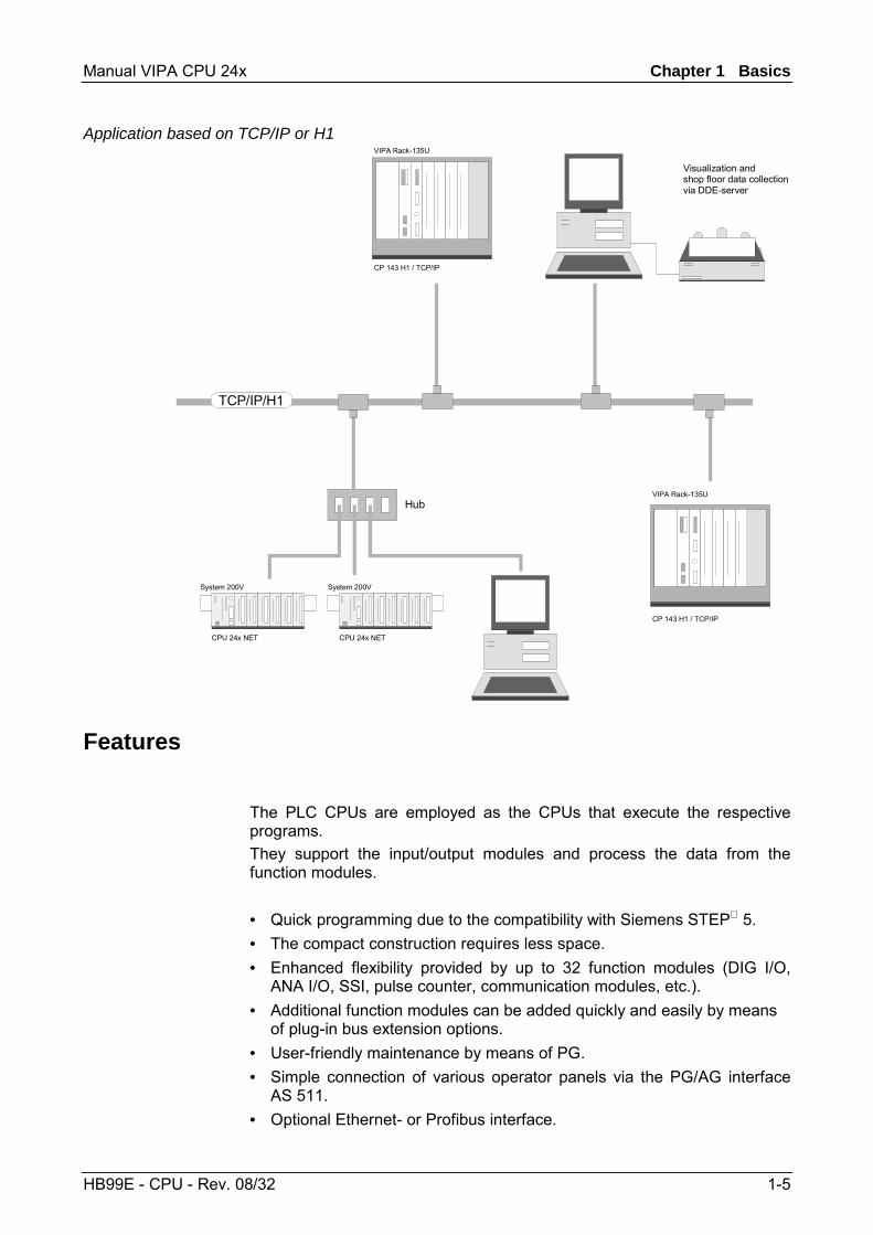
Application based on TCP/IP or H1
TCP/IP/H1
System 200V
CPU 24x NET
System 200V
CPU 24x NET
CP 143 H1 / TCP/IP
Visualization and shop floor data collection via DDE-server
VIPA Rack-135U
HubVIPA Rack-135U
CP 143 H1 / TCP/IP
Features
The PLC CPUs are employed as the CPUs that execute the respective programs. They support the input/output modules and process the data from the function modules. • Quick programming due to the compatibility with Siemens STEP 5. • The compact construction requires less space. • Enhanced flexibility provided by up to 32 function modules (DIG I/O,
ANA I/O, SSI, pulse counter, communication modules, etc.). • Additional function modules can be added quickly and easily by means
of plug-in bus extension options. • User-friendly maintenance by means of PG. • Simple connection of various operator panels via the PG/AG interface
AS 511. • Optional Ethernet- or Profibus interface.
Chapter 1 Basics Manual VIPA CPU 24x
1-6 HB99E - CPU - Rev. 08/32
Versions
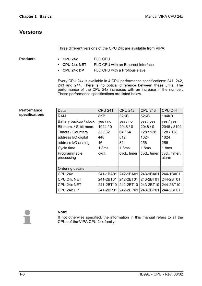
Three different versions of the CPU 24x are available from VIPA: • CPU 24x PLC CPU • CPU 24x NET PLC CPU with an Ethernet interface • CPU 24x DP PLC CPU with a Profibus slave Every CPU 24x is available in 4 CPU performance specifications: 241, 242, 243 and 244. There is no optical difference between these units. The performance of the CPU 24x increases with an increase in the number. These performance specifications are listed below.
Data CPU 241 CPU 242 CPU 243 CPU 244 RAM 8KB 32KB 52KB 104KB Battery backup / clock yes / no yes / no yes / yes yes / yes Bit-mem. / S-bit mem. 1024 / 0 2048 / 0 2048 / 0 2048 / 8192Timers / Counters 32 / 32 64 / 64 128 / 128 128 / 128 address I/O digital 448 512 1024 1024 address I/O analog 16 32 256 256 Cycle time 1.8ms 1.8ms 1.8ms 1.8ms Programmable processing
cycl. cycl., timer cycl., timer cycl., timer, alarm
Ordering details CPU 24x 241-1BA01 242-1BA01 243-1BA01 244-1BA01 CPU 24x NET 241-2BT01 242-2BT01 243-2BT01 244-2BT01 CPU 24x NET 241-2BT10 242-2BT10 243-2BT10 244-2BT10 CPU 24x DP 241-2BP01 242-2BP01 243-2BP01 244-2BP01
Note! If not otherwise specified, the information in this manual refers to all the CPUs of the VIPA CPU 24x family!
Products
Performance specifications
Manual VIPA CPU 24x Chapter 1 Basics
HB99E - CPU - Rev. 08/32 1-7
Operation of a CPU
These CPUs are intended for small and medium sized applications and are supplied with an integrated 24V power supply. The CPU contains a standard processor with internal program memory. In combination with system-200V peripherals the unit provides a powerful solution for process automation applications within the system-200V family. A CPU supports the following modes of operation: • cyclic operation • timer processing • alarm controlled operation • priority based processing Cyclic processing represents the major portion of all the processes that are executed in the CPU. Identical sequences of operations are repeated in a never ending cycle.
Where a process requires control signals at constant intervals you can initiate certain operations based upon a timer, e.g. not critical monitoring functions at one-second intervals.
If a process signal requires a quick response you would allocate this signal to an alarm controlled procedure. An alarm can activate a procedure in your program.
The above processes are handled by the CPU in accordance with their priority. Since a timer or an alarm event requires a quick reaction the CPU will interrupt the cyclic processing when these high-priority events occur to react to the event. Cyclic processing will resume once the reaction has been processed. This means that cyclic processing has the lowest priority.
General
Cyclic processing
Timer processing
Alarm controlled operation
Priority based processing
Chapter 1 Basics Manual VIPA CPU 24x
1-8 HB99E - CPU - Rev. 08/32
CPU 24x programs
The program that is present in every CPU is divided as follows: • System routine, • User program.
The system routine organizes all those functions and procedures of the CPU that are not connected with a specific control application.
This consists of all the functions that are required for the processing of a specific control application. The operating modules provide the interfaces to the system routines.
CPU 24x operands
The following series of operands is available for programming the CPU 24x:
The user program can quickly access the process image of the inputs and outputs PAA/PAE. You can manipulate the following types of data: - individual bits - bytes - words - double words. You can also gain direct access to peripheral modules via the bus from your user program. The following types of data are available: - bytes - words.
System routine
User program
Process image and periphery
Manual VIPA CPU 24x Chapter 1 Basics
HB99E - CPU - Rev. 08/32 1-9
Bit memory is an area of memory that is accessible to the user program by means of certain operations. Bit memory is intended to store frequently used working data. You can access the following types of data: - individual bits - bytes - words - double words The CPU 24x contains an additional area of bit memory, the S-bit memory. S-bit memory can not be used as working operand when calls are issued to function modules. The use of S-bit memory requires the PG system Siemens software "S5-DOS" as of version 3.0 or "S5-DOS/MT" from version 1.0 or you could also use the VIPA MC5 programming suite.
In your program you can load cell of the timer with a value between 10ms and 9990s. As soon as the user program executes a start-operation the value of this timer is decrement by the interval that you have specified until it reaches zero. You can load counter cells with an initial value (max. 999) and this increment or decrement these when required.
A data block contains constants or variables in the form of bytes, words or double words. You can always access the current data block by means of operands. You can access the following types of data: - individual bits - bytes - words - double words
Bit memory (M- and S-type bit memory)
Timers and counters
Data blocks

Chapter 1 Basics Manual VIPA CPU 24x
1-10 HB99E - CPU - Rev. 08/32
Manual VIPA CPU 24x Chapter 2 Hardware description
HB99E - CPU - Rev. 08/32 2-1
Chapter 2 Hardware description
The CPUs 24x are available in different versions that are described in this chapter. In addition to the hardware description the chapter also contains installation and commissioning instructions and applications for the memory modules.
Topic Page Chapter 2 Hardware description...................................................... 2-1
System overview .................................................................................. 2-2 Construction ......................................................................................... 2-6 Components......................................................................................... 2-8 Block diagram .................................................................................... 2-16 Commissioning................................................................................... 2-17 Booting behavior ................................................................................ 2-18 OVERALL RESET and reboot ............................................................ 2-19 Loading and saving an application program ....................................... 2-20 Test function STATUS/STATUS VAR and STEUERN........................ 2-22 MMC memory module ........................................................................ 2-24 Memory areas .................................................................................... 2-25 USTACK - output of system data by means of the PG ....................... 2-27 Significance of the USTACK indicators............................................... 2-32 Integrated FBs and OBs..................................................................... 2-34 Technical data.................................................................................... 2-36
Outline
Contents
Chapter 2 Hardware description Manual VIPA CPU 24x
2-2 HB99E - CPU - Rev. 08/32
System overview
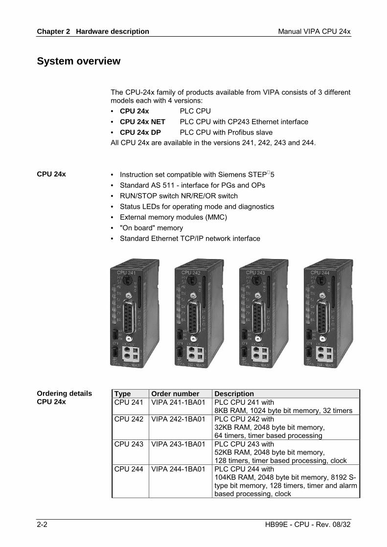
The CPU-24x family of products available from VIPA consists of 3 different models each with 4 versions: • CPU 24x PLC CPU • CPU 24x NET PLC CPU with CP243 Ethernet interface • CPU 24x DP PLC CPU with Profibus slave All CPU 24x are available in the versions 241, 242, 243 and 244.
• Instruction set compatible with Siemens STEP 5 • Standard AS 511 - interface for PGs and OPs • RUN/STOP switch NR/RE/OR switch • Status LEDs for operating mode and diagnostics • External memory modules (MMC) • "On board" memory • Standard Ethernet TCP/IP network interface
Type Order number Description CPU 241 VIPA 241-1BA01 PLC CPU 241 with
8KB RAM, 1024 byte bit memory, 32 timers CPU 242 VIPA 242-1BA01 PLC CPU 242 with
32KB RAM, 2048 byte bit memory, 64 timers, timer based processing
CPU 243 VIPA 243-1BA01 PLC CPU 243 with 52KB RAM, 2048 byte bit memory, 128 timers, timer based processing, clock
CPU 244 VIPA 244-1BA01 PLC CPU 244 with 104KB RAM, 2048 byte bit memory, 8192 S-type bit memory, 128 timers, timer and alarm based processing, clock
CPU 24x
Ordering details CPU 24x
Manual VIPA CPU 24x Chapter 2 Hardware description
HB99E - CPU - Rev. 08/32 2-3
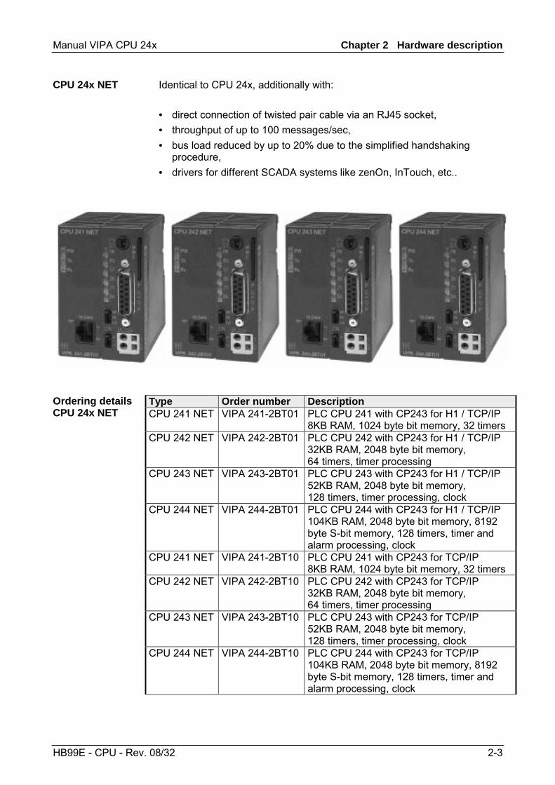
Identical to CPU 24x, additionally with: • direct connection of twisted pair cable via an RJ45 socket, • throughput of up to 100 messages/sec, • bus load reduced by up to 20% due to the simplified handshaking
procedure, • drivers for different SCADA systems like zenOn, InTouch, etc..
Type Order number Description CPU 241 NET VIPA 241-2BT01 PLC CPU 241 with CP243 for H1 / TCP/IP
8KB RAM, 1024 byte bit memory, 32 timers CPU 242 NET VIPA 242-2BT01 PLC CPU 242 with CP243 for H1 / TCP/IP
32KB RAM, 2048 byte bit memory, 64 timers, timer processing
CPU 243 NET VIPA 243-2BT01 PLC CPU 243 with CP243 for H1 / TCP/IP 52KB RAM, 2048 byte bit memory, 128 timers, timer processing, clock
CPU 244 NET VIPA 244-2BT01 PLC CPU 244 with CP243 for H1 / TCP/IP 104KB RAM, 2048 byte bit memory, 8192 byte S-bit memory, 128 timers, timer and alarm processing, clock
CPU 241 NET VIPA 241-2BT10 PLC CPU 241 with CP243 for TCP/IP 8KB RAM, 1024 byte bit memory, 32 timers
CPU 242 NET VIPA 242-2BT10 PLC CPU 242 with CP243 for TCP/IP 32KB RAM, 2048 byte bit memory, 64 timers, timer processing
CPU 243 NET VIPA 243-2BT10 PLC CPU 243 with CP243 for TCP/IP 52KB RAM, 2048 byte bit memory, 128 timers, timer processing, clock
CPU 244 NET VIPA 244-2BT10 PLC CPU 244 with CP243 for TCP/IP 104KB RAM, 2048 byte bit memory, 8192 byte S-bit memory, 128 timers, timer and alarm processing, clock
CPU 24x NET
Ordering details CPU 24x NET
Chapter 2 Hardware description Manual VIPA CPU 24x
2-4 HB99E - CPU - Rev. 08/32
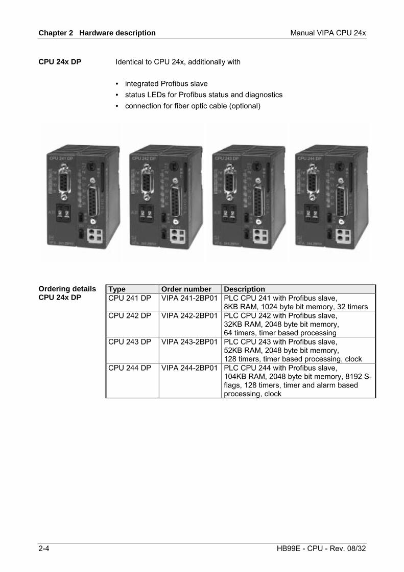
Identical to CPU 24x, additionally with • integrated Profibus slave • status LEDs for Profibus status and diagnostics • connection for fiber optic cable (optional)
Type Order number Description CPU 241 DP VIPA 241-2BP01 PLC CPU 241 with Profibus slave,
8KB RAM, 1024 byte bit memory, 32 timers CPU 242 DP VIPA 242-2BP01 PLC CPU 242 with Profibus slave,
32KB RAM, 2048 byte bit memory, 64 timers, timer based processing
CPU 243 DP VIPA 243-2BP01 PLC CPU 243 with Profibus slave, 52KB RAM, 2048 byte bit memory, 128 timers, timer based processing, clock
CPU 244 DP VIPA 244-2BP01 PLC CPU 244 with Profibus slave, 104KB RAM, 2048 byte bit memory, 8192 S-flags, 128 timers, timer and alarm based processing, clock
CPU 24x DP
Ordering details CPU 24x DP
Manual VIPA CPU 24x Chapter 2 Hardware description
HB99E - CPU - Rev. 08/32 2-5
A CPU is an intelligent module. Your control-programs are executed here. You can select one of four CPUs, depending on the performance required from your system. The higher the performance of the CPU, the more user memory is available. The CPU 24x is intended for small to medium applications and it has an integrated 24V power supply. The CPUs contain a standard-processor with internal program memory as well as Flash-ROM for the storage of user-programs. In addition, every CPU 24x is equipped with a socket for a memory module, which is located on the front. Every CPU has a PG/OP-connector and is compatible with the Siemens STEP® 5 instruction set. These modules have the performance of the 90U to 115U/944. This series of CPUs provides access to the peripheral modules of the System 200V. You can interrogate sensors and control drives by means of standardized commands and programs. The unit can address a maximum of 32 modules. The standard PG/OP-interface provides access to other devices. The operating and display elements are arranged in a similar manner as those of the CPU for the 115U. The same applies to the indication of operating modes. The remainder of this description refers to the CPUs of the CPU 24x family since the CPUs 241 through 244 are functionally identical with the exception of the memory size.
• Instruction set compatible with Siemens STEP 5 • User-addressable via DB1 • Integrated 24V power supply • 8 ... 104 KB memory • Battery backed clock (only CPU 243 and CPU 244) • Memory-card socket • PG/OP interface • Integrated VBUS controller for peripheral modules • User programs can be saved in the internal Flash-ROM • Integrated FBs and OBs • 128 timers • 128 counters • 2048 byte bit memory • 8192 byte of S-bit memory
General
Properties
Chapter 2 Hardware description Manual VIPA CPU 24x
2-6 HB99E - CPU - Rev. 08/32
Construction
2
3
4
5
712
6
PW
RN
ST
QV
ZY
BA
CPU 244RNST
X 23 4VIPA 244-1BA01
DC24V
+-
ON
NRREOR
PG-OP
1
2
3
4
5
6
7
8
9
10
11
12
13
14
15
MMC
1CPU 24x front view
CPU 24x NET front view
CPU 24x-2BT01
5
7
6
PW
RN
ST
QV
ZY
BA
RNST
DC24V
+-
ON
NRREOR
PG-OP
12
1
2
3
4
5
6
7
8
9
10
11
12
13
14
15
MMC
PW
Tx
Rx
IX-Data
X 23 4VIPA 244-2BT01
CPU 244 NET
TPTx
Rx9
8
2
1
3
4
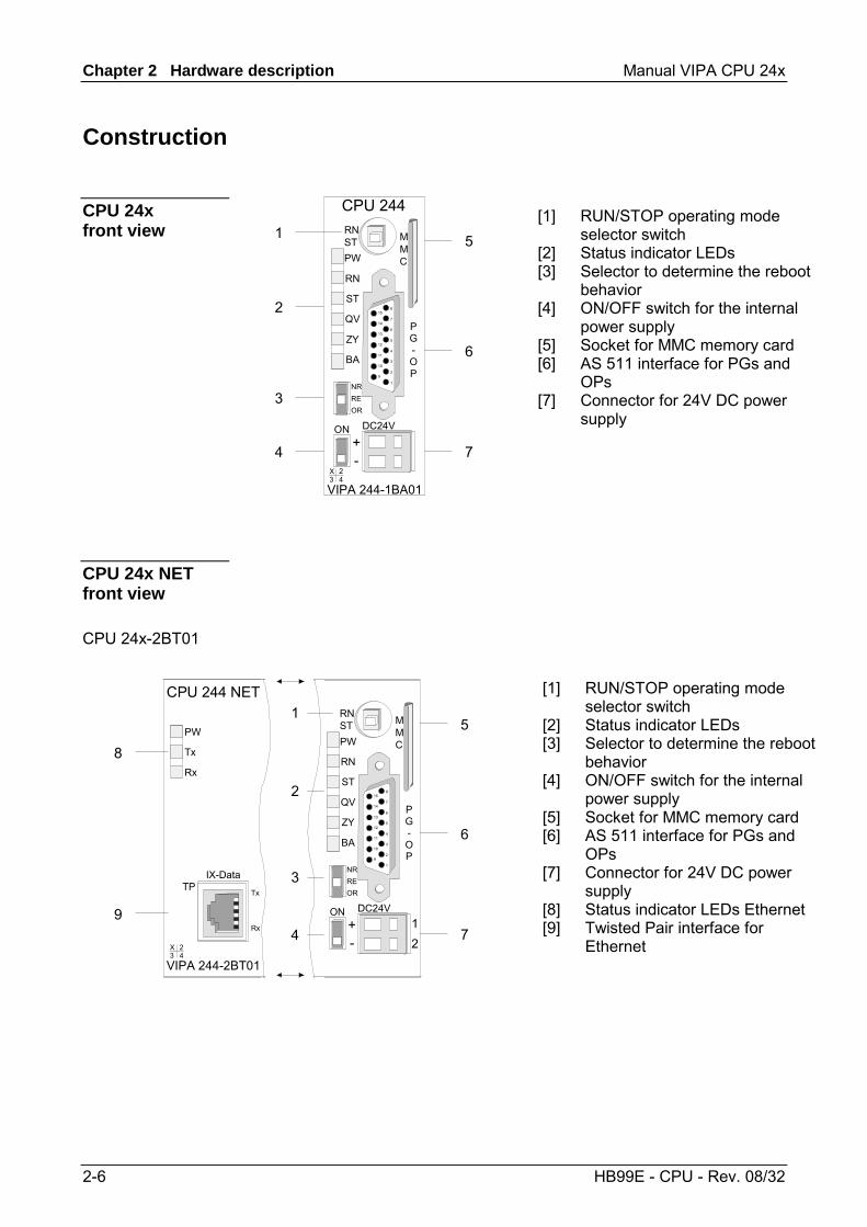
[1] RUN/STOP operating mode selector switch
[2] Status indicator LEDs [3] Selector to determine the reboot
behavior [4] ON/OFF switch for the internal
power supply [5] Socket for MMC memory card [6] AS 511 interface for PGs and
OPs [7] Connector for 24V DC power
supply
[1] RUN/STOP operating mode
selector switch [2] Status indicator LEDs [3] Selector to determine the reboot
behavior [4] ON/OFF switch for the internal
power supply [5] Socket for MMC memory card [6] AS 511 interface for PGs and
OPs [7] Connector for 24V DC power
supply [8] Status indicator LEDs Ethernet [9] Twisted Pair interface for
Ethernet

Manual VIPA CPU 24x Chapter 2 Hardware description
HB99E - CPU - Rev. 08/32 2-7
CPU 24x-2BT10
5
7
6
PW
RN
ST
QV
ZY
BA
RNST
DC24V
+-
ON
NRREOR
PG-OP
12
1
2
3
4
5
6
7
8
9
10
11
12
13
14
15
MMC
X 23 4VIPA 244-2BT10
CPU 244 NET
TP10/100
9
8
2
1
3
4
RN
ST
IF
L/A
S
CPU 24x DP front view
5
7
6
PW
RN
ST
QV
ZY
BA
RNST
DC24V
+-
ON
NRREOR
PG-OP
12
1
2
3
4
5
6
7
8
9
10
11
12
13
14
15
MMC
9
8
2
1
3
4X 23 4
VIPA 244-2BP01
CPU 244 DP
PW
ER
RD
DE
ADR. 9 9
10
[1] RUN/STOP operating mode
selector switch [2] Status indicator LED’s [3] Selector to determine the reboo
behaviour [4] ON/OFF switch for the internal
power supply [5] Socket for MMC menory card [6] AS 511 interface for PGs and
OPs [7] Connector for 24V DC power
supply [8] Profibus status indicator LED’s[9] Profibus address selector [10] Profibus interface
[1] RUN/STOP operating mode
selector switch [2] Status indicator LEDs [3] Selector to determine the reboot
behavior [4] ON/OFF switch for the internal
power supply [5] Socket for MMC memory card [6] AS 511 interface for PGs and
OPs [7] Connector for 24V DC power
supply [8] Status indicator LEDs Ethernet [9] Twisted Pair interface for
Ethernet
Chapter 2 Hardware description Manual VIPA CPU 24x
2-8 HB99E - CPU - Rev. 08/32
Components
The components of the CPU 24x that are described here are also components of all the other CPUs presented in this manual.
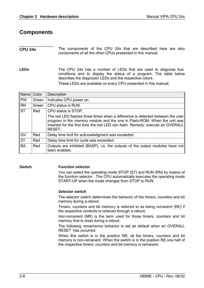
The CPU 24x has a number of LEDs that are used to diagnose bus conditions and to display the status of a program. The table below describes the diagnostic LEDs and the respective colors. These LEDs are available on every CPU presented in this manual.
Name Color Description PW Green Indicates CPU power on. RN Green CPU status is RUN. ST Red CPU status is STOP.
The red LED flashes three times when a difference is detected between the user program in the memory module and the one in Flash-ROM. When the unit was inserted for the first time the red LED can flash. Remedy: execute an OVERALL RESET.
QV Red Delay time limit for acknowledgment was exceeded. ZY Red Delay time limit for cycle was exceeded. BA Red Outputs are inhibited (BASP), i.e. the outputs of the output modules have not
been enabled.
Function selector You can select the operating mode STOP (ST) and RUN (RN) by means of the function selector . The CPU automatically executes the operating mode START-UP when the mode changes from STOP to RUN. Selector switch The selector switch determines the behavior of the timers, counters and bit memory during a reboot. Timers, counters and bit memory is referred to as being remanent (RE) if the respective contents is retained through a reboot. Non-remanent (NR) is the term used for those timers, counters and bit memory that is reset during a reboot. The following remamence behavior is set as default when an OVERALL RESET has occurred: When this switch is in the position NR, all the timers, counters and bit memory is non-remanent. When the switch is in the position RE one half of the respective timers, counters and bit memory is remanent.
CPU 24x
LEDs
Switch
Manual VIPA CPU 24x Chapter 2 Hardware description
HB99E - CPU - Rev. 08/32 2-9
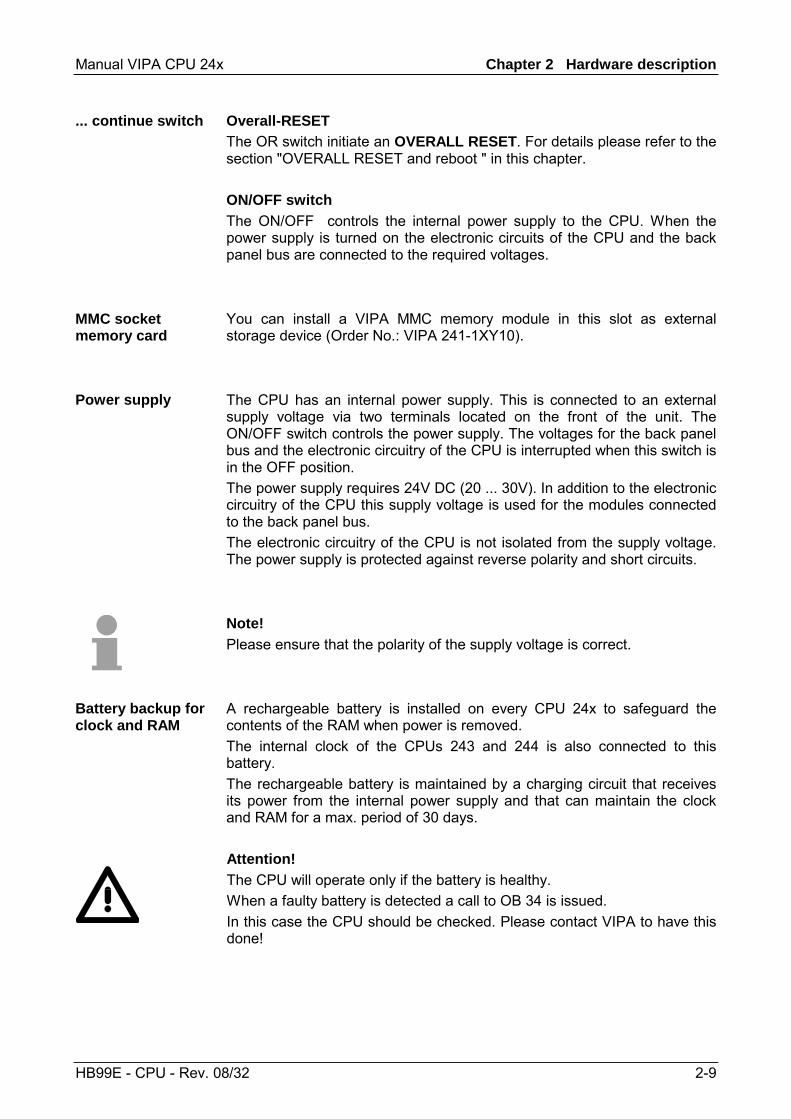
Overall-RESET The OR switch initiate an OVERALL RESET. For details please refer to the section "OVERALL RESET and reboot " in this chapter. ON/OFF switch The ON/OFF controls the internal power supply to the CPU. When the power supply is turned on the electronic circuits of the CPU and the back panel bus are connected to the required voltages.
You can install a VIPA MMC memory module in this slot as external storage device (Order No.: VIPA 241-1XY10).
The CPU has an internal power supply. This is connected to an external supply voltage via two terminals located on the front of the unit. The ON/OFF switch controls the power supply. The voltages for the back panel bus and the electronic circuitry of the CPU is interrupted when this switch is in the OFF position. The power supply requires 24V DC (20 ... 30V). In addition to the electronic circuitry of the CPU this supply voltage is used for the modules connected to the back panel bus. The electronic circuitry of the CPU is not isolated from the supply voltage. The power supply is protected against reverse polarity and short circuits.
Note! Please ensure that the polarity of the supply voltage is correct.
A rechargeable battery is installed on every CPU 24x to safeguard the contents of the RAM when power is removed. The internal clock of the CPUs 243 and 244 is also connected to this battery. The rechargeable battery is maintained by a charging circuit that receives its power from the internal power supply and that can maintain the clock and RAM for a max. period of 30 days. Attention! The CPU will operate only if the battery is healthy. When a faulty battery is detected a call to OB 34 is issued. In this case the CPU should be checked. Please contact VIPA to have this done!
... continue switch
MMC socket memory card
Power supply
Battery backup for clock and RAM
Chapter 2 Hardware description Manual VIPA CPU 24x
2-10 HB99E - CPU - Rev. 08/32
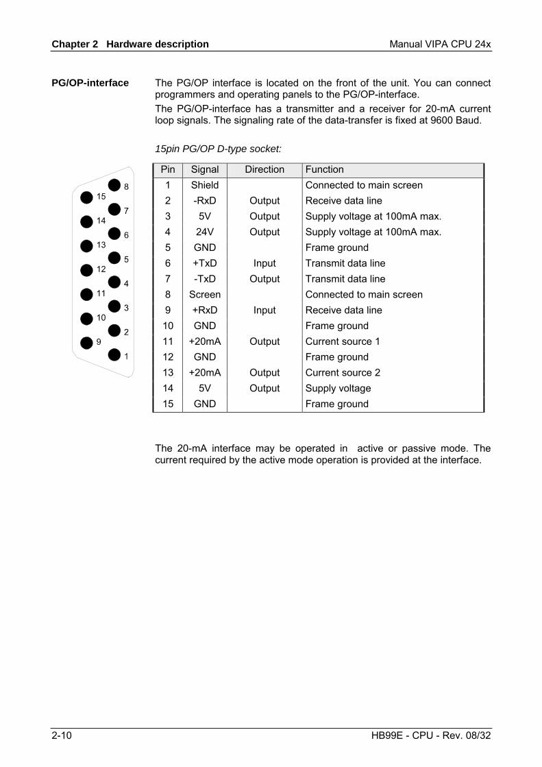
The PG/OP interface is located on the front of the unit. You can connect programmers and operating panels to the PG/OP-interface. The PG/OP-interface has a transmitter and a receiver for 20-mA current loop signals. The signaling rate of the data-transfer is fixed at 9600 Baud. 15pin PG/OP D-type socket:
Pin Signal Direction Function 1 Shield Connected to main screen 2 -RxD Output Receive data line 3 5V Output Supply voltage at 100mA max. 4 24V Output Supply voltage at 100mA max. 5 GND Frame ground 6 +TxD Input Transmit data line 7 -TxD Output Transmit data line 8 Screen Connected to main screen 9 +RxD Input Receive data line 10 GND Frame ground 11 +20mA Output Current source 1 12 GND Frame ground 13 +20mA Output Current source 2 14 5V Output Supply voltage
15 GND Frame ground
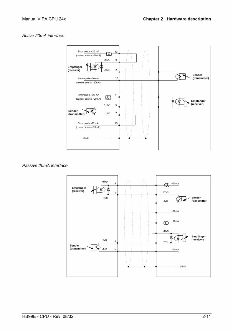
The 20-mA interface may be operated in active or passive mode. The current required by the active mode operation is provided at the interface.
PG/OP-interface
Manual VIPA CPU 24x Chapter 2 Hardware description
HB99E - CPU - Rev. 08/32 2-11
Active 20mA interface
+RxD
shield
13
9
2
12
11
6
7
15
Stromquelle +20 mA
(current source +20mA)
-RxD
+TxD
-TxDSender(transmitter)
Empfänger(receiver)
Stromquelle +20 mA
(current source +20mA)
Stromquelle -20 mA
(current source -20mA)
Stromquelle -20 mA
(current source -20mA)
Empfänger(receiver)
Sender(transmitter)
Passive 20mA interface
+RxD+20mA
-RxD
+20mA
-TxD
+RxD
shield
9
+TxD 2
Empfänger(receiver)
-RxD+TxD 6
-TxD -20mA 7
-20mA
Sender(transmitter)
Sender(transmitter)
Empfänger(receiver)
Chapter 2 Hardware description Manual VIPA CPU 24x
2-12 HB99E - CPU - Rev. 08/32
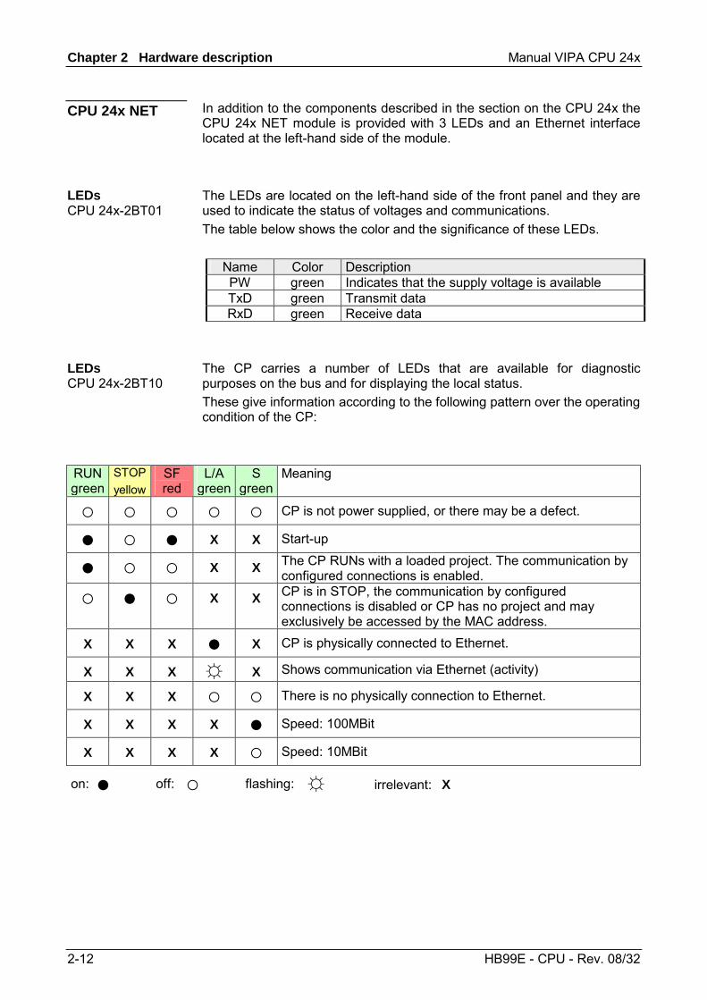
In addition to the components described in the section on the CPU 24x the CPU 24x NET module is provided with 3 LEDs and an Ethernet interface located at the left-hand side of the module.
The LEDs are located on the left-hand side of the front panel and they are used to indicate the status of voltages and communications. The table below shows the color and the significance of these LEDs.
Name Color Description PW green Indicates that the supply voltage is available TxD green Transmit data RxD green Receive data
The CP carries a number of LEDs that are available for diagnostic purposes on the bus and for displaying the local status. These give information according to the following pattern over the operating condition of the CP:
RUN green
STOP yellow
SF red
L/A green
S green
Meaning
○ ○ ○ ○ ○ CP is not power supplied, or there may be a defect.
● ○ ● X X Start-up
● ○ ○ X X The CP RUNs with a loaded project. The communication by configured connections is enabled.
○ ● ○ X X CP is in STOP, the communication by configured connections is disabled or CP has no project and may exclusively be accessed by the MAC address.
X X X ● X CP is physically connected to Ethernet.
X X X ☼ X Shows communication via Ethernet (activity)
X X X ○ ○ There is no physically connection to Ethernet.
X X X X ● Speed: 100MBit
X X X X ○ Speed: 10MBit
on: ● off: ○ flashing: ☼ irrelevant: X
CPU 24x NET
LEDs CPU 24x-2BT01
LEDs CPU 24x-2BT10

Manual VIPA CPU 24x Chapter 2 Hardware description
HB99E - CPU - Rev. 08/32 2-13
An RJ45 socket provides the interface to the twisted pair cable required for Ethernet. The pin-assignment of this socket is as follows: 8pin RJ45 socket:
Pin Signal 1 Transmit + 2 Transmit - 3 Receive + 4 - 5 - 6 Receive - 7 - 8 -
A twisted pair network can only have a star topology. For this purpose hub is required as the central node:
Ethernet interface
Star topology
Chapter 2 Hardware description Manual VIPA CPU 24x
2-14 HB99E - CPU - Rev. 08/32
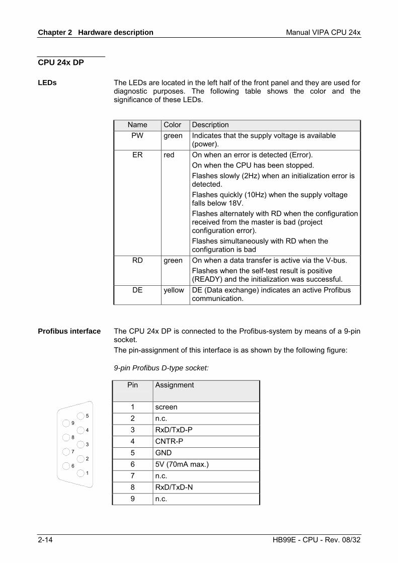
The LEDs are located in the left half of the front panel and they are used for diagnostic purposes. The following table shows the color and the significance of these LEDs.
Name Color Description PW green Indicates that the supply voltage is available
(power). ER red On when an error is detected (Error).
On when the CPU has been stopped. Flashes slowly (2Hz) when an initialization error is detected. Flashes quickly (10Hz) when the supply voltage falls below 18V. Flashes alternately with RD when the configurationreceived from the master is bad (project configuration error). Flashes simultaneously with RD when the configuration is bad
RD green On when a data transfer is active via the V-bus. Flashes when the self-test result is positive (READY) and the initialization was successful.
DE yellow DE (Data exchange) indicates an active Profibus communication.
The CPU 24x DP is connected to the Profibus-system by means of a 9-pin socket. The pin-assignment of this interface is as shown by the following figure:
9-pin Profibus D-type socket:
Pin
Assignment
1 screen 2 n.c. 3 RxD/TxD-P 4 CNTR-P 5 GND 6 5V (70mA max.) 7 n.c. 8 RxD/TxD-N
5
4
3
2
1
9
8
7
6
9 n.c.
CPU 24x DP
LEDs
Profibus interface
Manual VIPA CPU 24x Chapter 2 Hardware description
HB99E - CPU - Rev. 08/32 2-15
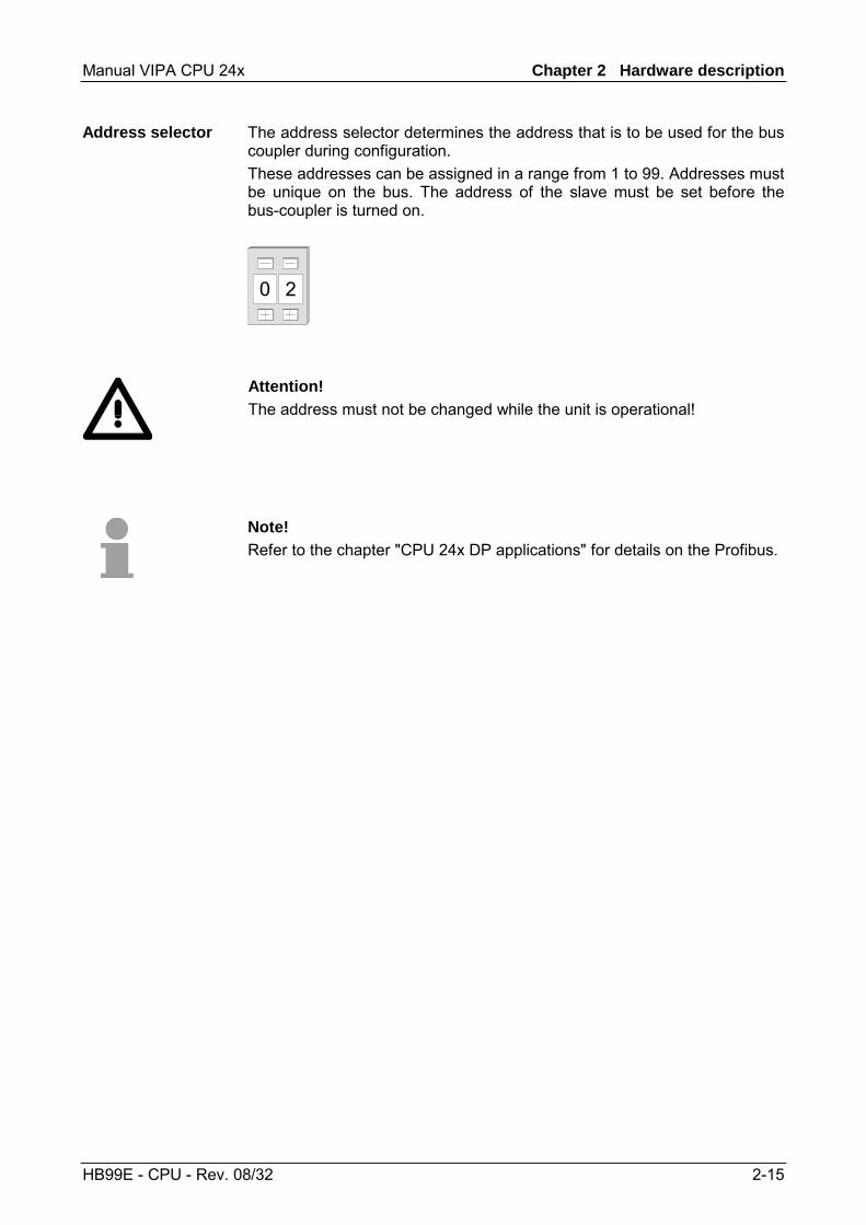
The address selector determines the address that is to be used for the bus coupler during configuration. These addresses can be assigned in a range from 1 to 99. Addresses must be unique on the bus. The address of the slave must be set before the bus-coupler is turned on.
0 2
Attention! The address must not be changed while the unit is operational!
Note! Refer to the chapter "CPU 24x DP applications" for details on the Profibus.
Address selector
Chapter 2 Hardware description Manual VIPA CPU 24x
2-16 HB99E - CPU - Rev. 08/32
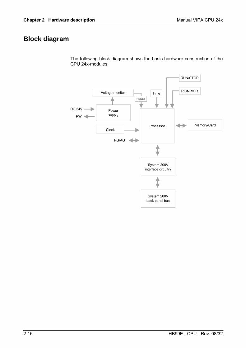
Block diagram
The following block diagram shows the basic hardware construction of the CPU 24x-modules:
Processor
System 200Vinterface circuitry
System 200Vback panel bus
Memory-Card
Time
Clock
PG/AG
Voltage monitor
DC 24V
PW
Powersupply
RESET
RUN/STOP
RE/NR/OR
Manual VIPA CPU 24x Chapter 2 Hardware description
HB99E - CPU - Rev. 08/32 2-17
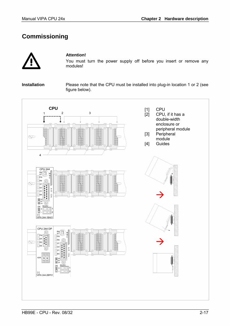
Commissioning
Attention! You must turn the power supply off before you insert or remove any modules!
Please note that the CPU must be installed into plug-in location 1 or 2 (see figure below).
PW
RN
ST
QV
ZY
BA
RNST
DC24V
+-
ON
NRREOR
PG-OP
12
1
2
3
4
5
6
7
8
9
10
11
12
13
14
15
MMC
X 23 4VIPA 244-2BP01
CPU 244 DP
PW
ER
RD
DE
ADR. 9 9
X 23 4VIPA 244-1BA01
CPU 244
PW
RN
ST
QV
ZY
BA
RNST
DC24V
+-
ON
NRREOR
PG-OP
12
1
2
3
4
5
6
7
8
9
10
11
12
13
14
15
MMC
1 2
4
3
Installation
[1] CPU [2] CPU, if it has a
double-width enclosure or peripheral module
[3] Peripheral module
[4] Guides
CPU
Chapter 2 Hardware description Manual VIPA CPU 24x
2-18 HB99E - CPU - Rev. 08/32
Booting behavior
The booting behavior is the procedure that is executed between the STOP-RUN change of state (manual reboot) and POWER-ON-RUN. When the processor has been turned on it analyzes the modules that are installed on the back-panel bus and stores the respective values. LEDs BA, RN and ST are at this time. A start-up OB is processed while the CPU is in start-up mode: • during a manual reboot: OB 21, • after POWER-ON and with switch setting RN: OB 22.
Attention! Modules must be installed in the correct plug-in location in the System 200V. The status of the backup-battery must be healthy to allow the CPU to start properly.
After a POWER-ON the application program is loaded from flash-ROM, or if the memory module is installed the program is transferred from the memory module into RAM and saved in the flash-ROM. This is subject to the following conditions: • A valid application program is available from the flash-ROM or from the
memory module. • The option for reloading application programs after POWER-ON has
been activated. For details please refer to "Loading and saving an application program" below.
Start-up
Automatically reloading an application program
Manual VIPA CPU 24x Chapter 2 Hardware description
HB99E - CPU - Rev. 08/32 2-19
OVERALL RESET and reboot
During the OVERALL RESET the entire user memory (RAM) is erased. Data located in the flash-ROM is not affected. Proceed as follows to initiate an OVERALL RESET: • Place the function selector in position "STOP". • Turn the power on. → The following LEDs on the CPU must be on: • red LED "STOP" • red LED "BASP". • Hold the operating mode push-button in position "OR" and move the
operating mode switch from "ST" to "RN". • Repeat this process a few times. The red LED "ST" will be turned off for
a short while. → The CPU has been reset and the red LED "ST" is on permanently. • Release the operating mode push-button. • Move the function selector to "ST" and back to "RN".
→ The red "STOP" LED is turned off, the green "RUN" LED is turned on, the red "BASP" LED is turned off.
While the CPU is busy executing the boot procedure: • the LEDs "BASP"; and "RUN" "STOP" are turned on simultaneously, • the output modules are disabled, outputs are at “0” level, • the inputs and outputs in the process image are at signal level "0", • the cycle monitoring time is deactivated. The status of the CPU is RUN as soon as the BASP-LED is turned off.
After a REBOOT the application program is automatically loaded into RAM from the flash-ROM if: • a valid application program is located in the flash-ROM, • the reload after REBOOT has been activated. For details please refer to "Loading and saving an application program" below.
OVERALL RESET
Reboot
Reloading of program after a REBOOT

Chapter 2 Hardware description Manual VIPA CPU 24x
2-20 HB99E - CPU - Rev. 08/32
Loading and saving an application program
The CPU has a facility to load or save the application program: • in the internal flash-ROM, • externally into a memory module (MMC). The system data cell BS 38 coordinates saving. The following settings are possible:
Setting BS 38 data Explanation Save to flash-ROM and to MMC. 0001h The application program is saved to flash-
ROM and to the MMC if this is inserted. Save to flash-ROM and to MMC. Reload from MMC or flash-ROM after POWER-ON.
0003h The application program is saved to flash-ROM and to the MMC if this is inserted. After POWER-ON the program is loaded from the MMC if the MMC was installed or if the MMC was not installed it is loaded from the flash-ROM.
Save to flash-ROM and to MMC. Reload after REBOOT only from flash-ROM.
0005h The application program is saved to the flash-ROM. After a REBOOT the program is reloaded from the flash-ROM.
Save to flash-ROM and to MMC. Reload from MMC or flash-ROM after POWER-ON and reload after REBOOT only from flash-ROM.
0007h The application program is saved to flash-ROM. The program is reloaded after POWER ON and after REBOOT.
Declare application program in flash-ROM and on MMC invalid.
FFFFh The program in the flash-ROM or the MMC is erased. This process is irreversible.
The program is saved during the STOP/RUN transition. The contents of the BS cell 38 are set to zero when the program has been saved.
Flash-ROM and MMC

Manual VIPA CPU 24x Chapter 2 Hardware description
HB99E - CPU - Rev. 08/32 2-21
When the program has been saved the settings are visible in BS 7 or in the U-stack. Check via BS 7
BS 7 Bit No.
Name in the U-stack
Description
3 NB Load programs from MMC or flash-ROM after every POWER ON.
4 NB Load program from flash-ROM after REBOOT.
Check in U-stack
Displaying the settings
Reload after REBOOT
Reload after POWER ON
Chapter 2 Hardware description Manual VIPA CPU 24x
2-22 HB99E - CPU - Rev. 08/32
Test function STATUS/STATUS VAR and STEUERN
The status of the operands and the VKE can be displayed by means of the test function STATUS and STATUS VAR. Since STATUS is program-dependent it displays the status during the cycle. STATUS VAR displays the status of the signals at the end of the cycle.
This test function displays the current status and the VKE of the different operands while the program is being executed. It is also possible to enter corrections to the program.
Note! When using the test function “STATUS” the PLC must be in RUN mode.
The processing of statuses can be interrupted by means of jump commands or by timer and process-related alarms. At the breakpoint the CPU stops collecting data for the status display and instead of the required data it only provides the PG with data containing the value 0. For this reason jumps or time and process alarms can result in the value displayed during program execution remaining at 0 for the items below: • the result of the logical operation VKE • Status / AKKU 1 • AKKU 2 • Condition byte • absolute memory address SAZ. In this case SAZ is followed by a "?". The interruption of the processing of statuses does not change the execution of the program but it only shows that the data displayed is no longer valid after from the point where the interrupt occurred.
STATUS
Manual VIPA CPU 24x Chapter 2 Hardware description
HB99E - CPU - Rev. 08/32 2-23
This test function returns the condition of a selected operand (inputs, outputs, flags, data word, counters or timers) at the end of program-execution. This information is obtained from the process image of the selected operands. During the "processing check" or in operating mode STOP the periphery is read directly from the inputs. Otherwise only the process image of the selected operands is displayed.
STEUERN (control) of outputs It is possible to check the wiring and proper operation of output-modules. You can set outputs to any desired status with or without a control program. The process image is not modified but outputs are no longer inhibited.
Note! The operating mode of the PLC must be STOP for the test function to operate. This function must only be executed when the voltage has been removed from the load.
STEUERN (control) of variables The following variables may be modified: E, A, M, T, Z, and D. The process image of binary and digital operands is modified independently of the operating mode of the PLC. When the operating mode is RUN the program is executed with the modified process variable. When the program continues they may, however, be modified again without notification. Process variables are controlled asynchronously with respect to the execution sequence of the program. Features: • Variables E, A and M must only be modified byte-wise or word-wise in
the process image. • In case of variables T and Z with the format KM and KH
additionally a “JA” (yes) must be entered into the mask VOREINSTELLUNGEN (default settings) in the input field SYSTEM-BEFEHLE (system commands), observe the control of the edge flags.
• The display routine for the signal condition is terminated when an error is detected in the entered format or operand. In this case the PG will issue the message "KEIN STEUERN MÖGLICH" (control not possible).
STATUS VAR
STEUERN
STEUERN VAR
Chapter 2 Hardware description Manual VIPA CPU 24x
2-24 HB99E - CPU - Rev. 08/32
MMC memory module
The VIPA Multi Media Card (MMC) provides the external memory. The memory module is obtainable from VIPA under the order no.: VIPA 241-1XY10. When used with the CPU 24x the memory module is treated identically to the internal flash-ROM of the CPU 24x.
When the MMC has been installed the write command stores the application program in the flash-ROM as well as the MMC. The write command is controlled by means of the system data cell BS 38 (see "Loading and saving the application program"). During the write process the LEDs of the CPU flash in a running sequence. If the transfer is successful the bit ASPNEP is set in USTACK (memory module EPROM - BS 7 bit 15).
The application program can only be transferred from the MMC into the CPU after a POWER ON event. The running light display of the red LEDs on the CPU indicates that the transfer is active. When the application program has been transferred into RAM it is transferred into flash-ROM. On this occasion the red STOP-LED flashes three times. The green RUN-LED flashes three times when the transfer from the MMC into the CPU has been successful. An OVERALL RESET of the CPU takes place if the MMC does not contain a valid application program or if the transfer should fail. In either of these cases the application program in flash-ROM is not modified.
Note! It must be noted that the memory size has been matched to the type of CPU! A CPU 244 can only read an MMC that is marked for use in a CPU 244. Application program produce by a CPU 241, 242 or 243 and that were saved to the MMC can be exchanged amongst each other. On this occasion the program-size is checked when it is read into the CPU. If the application program is larger than the application memory of the CPU the contents of the MMC is not transferred into CPU. Before an application program is transferred into internal flash-ROM or into the MMC you should compress the program.
Transfer CPU →→→→ MMC
Transfer MMC →→→→ CPU
Manual VIPA CPU 24x Chapter 2 Hardware description
HB99E - CPU - Rev. 08/32 2-25
Memory areas
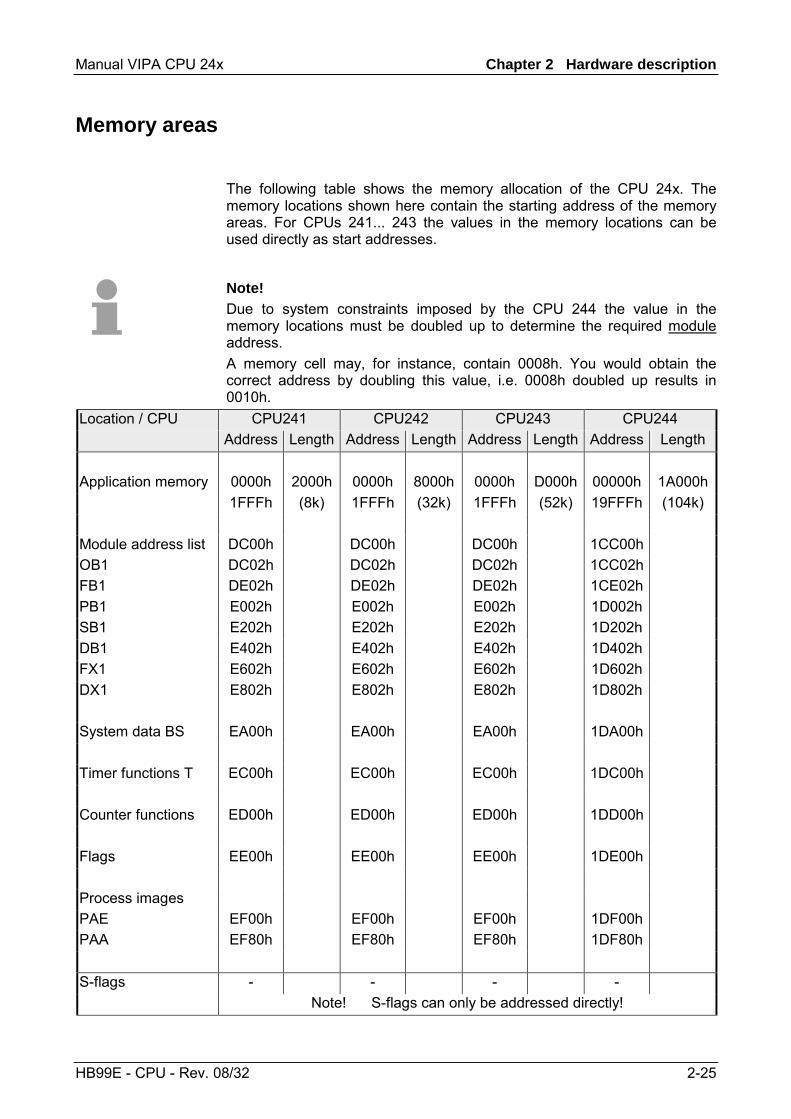
The following table shows the memory allocation of the CPU 24x. The memory locations shown here contain the starting address of the memory areas. For CPUs 241... 243 the values in the memory locations can be used directly as start addresses.
Note! Due to system constraints imposed by the CPU 244 the value in the memory locations must be doubled up to determine the required module address. A memory cell may, for instance, contain 0008h. You would obtain the correct address by doubling this value, i.e. 0008h doubled up results in 0010h.
Location / CPU CPU241 CPU242 CPU243 CPU244 Address Length Address Length Address Length Address Length Application memory 0000h 2000h 0000h 8000h 0000h D000h 00000h 1A000h 1FFFh (8k) 1FFFh (32k) 1FFFh (52k) 19FFFh (104k) Module address list DC00h DC00h DC00h 1CC00h OB1 DC02h DC02h DC02h 1CC02h FB1 DE02h DE02h DE02h 1CE02h PB1 E002h E002h E002h 1D002h SB1 E202h E202h E202h 1D202h DB1 E402h E402h E402h 1D402h FX1 E602h E602h E602h 1D602h DX1 E802h E802h E802h 1D802h System data BS EA00h EA00h EA00h 1DA00h Timer functions T EC00h EC00h EC00h 1DC00h Counter functions ED00h ED00h ED00h 1DD00h Flags EE00h EE00h EE00h 1DE00h Process images PAE EF00h EF00h EF00h 1DF00h PAA EF80h EF80h EF80h 1DF80h S-flags - - - - Note! S-flags can only be addressed directly!
Chapter 2 Hardware description Manual VIPA CPU 24x
2-26 HB99E - CPU - Rev. 08/32
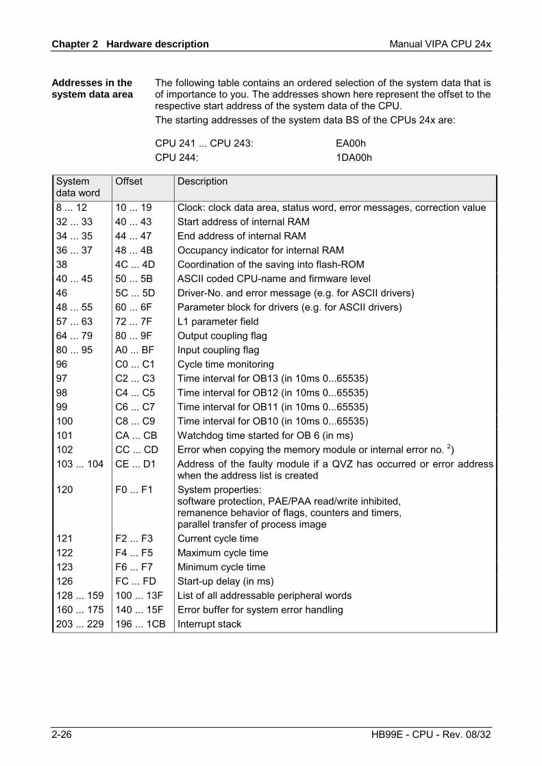
The following table contains an ordered selection of the system data that is of importance to you. The addresses shown here represent the offset to the respective start address of the system data of the CPU. The starting addresses of the system data BS of the CPUs 24x are:
CPU 241 ... CPU 243: EA00h CPU 244: 1DA00h
System data word
Offset Description
8 ... 12 10 ... 19 Clock: clock data area, status word, error messages, correction value 32 ... 33 40 ... 43 Start address of internal RAM 34 ... 35 44 ... 47 End address of internal RAM 36 ... 37 48 ... 4B Occupancy indicator for internal RAM 38 4C ... 4D Coordination of the saving into flash-ROM 40 ... 45 50 ... 5B ASCII coded CPU-name and firmware level 46 5C ... 5D Driver-No. and error message (e.g. for ASCII drivers) 48 ... 55 60 ... 6F Parameter block for drivers (e.g. for ASCII drivers) 57 ... 63 72 ... 7F L1 parameter field 64 ... 79 80 ... 9F Output coupling flag 80 ... 95 A0 ... BF Input coupling flag 96 C0 ... C1 Cycle time monitoring 97 C2 ... C3 Time interval for OB13 (in 10ms 0...65535) 98 C4 ... C5 Time interval for OB12 (in 10ms 0...65535) 99 C6 ... C7 Time interval for OB11 (in 10ms 0...65535) 100 C8 ... C9 Time interval for OB10 (in 10ms 0...65535) 101 CA ... CB Watchdog time started for OB 6 (in ms) 102 CC ... CD Error when copying the memory module or internal error no. 2) 103 ... 104 CE ... D1 Address of the faulty module if a QVZ has occurred or error address
when the address list is created 120 F0 ... F1 System properties:
software protection, PAE/PAA read/write inhibited, remanence behavior of flags, counters and timers, parallel transfer of process image
121 F2 ... F3 Current cycle time 122 F4 ... F5 Maximum cycle time 123 F6 ... F7 Minimum cycle time 126 FC ... FD Start-up delay (in ms) 128 ... 159 100 ... 13F List of all addressable peripheral words 160 ... 175 140 ... 15F Error buffer for system error handling 203 ... 229 196 ... 1CB Interrupt stack
Addresses in the system data area
Manual VIPA CPU 24x Chapter 2 Hardware description
HB99E - CPU - Rev. 08/32 2-27
USTACK - output of system data by means of the PG
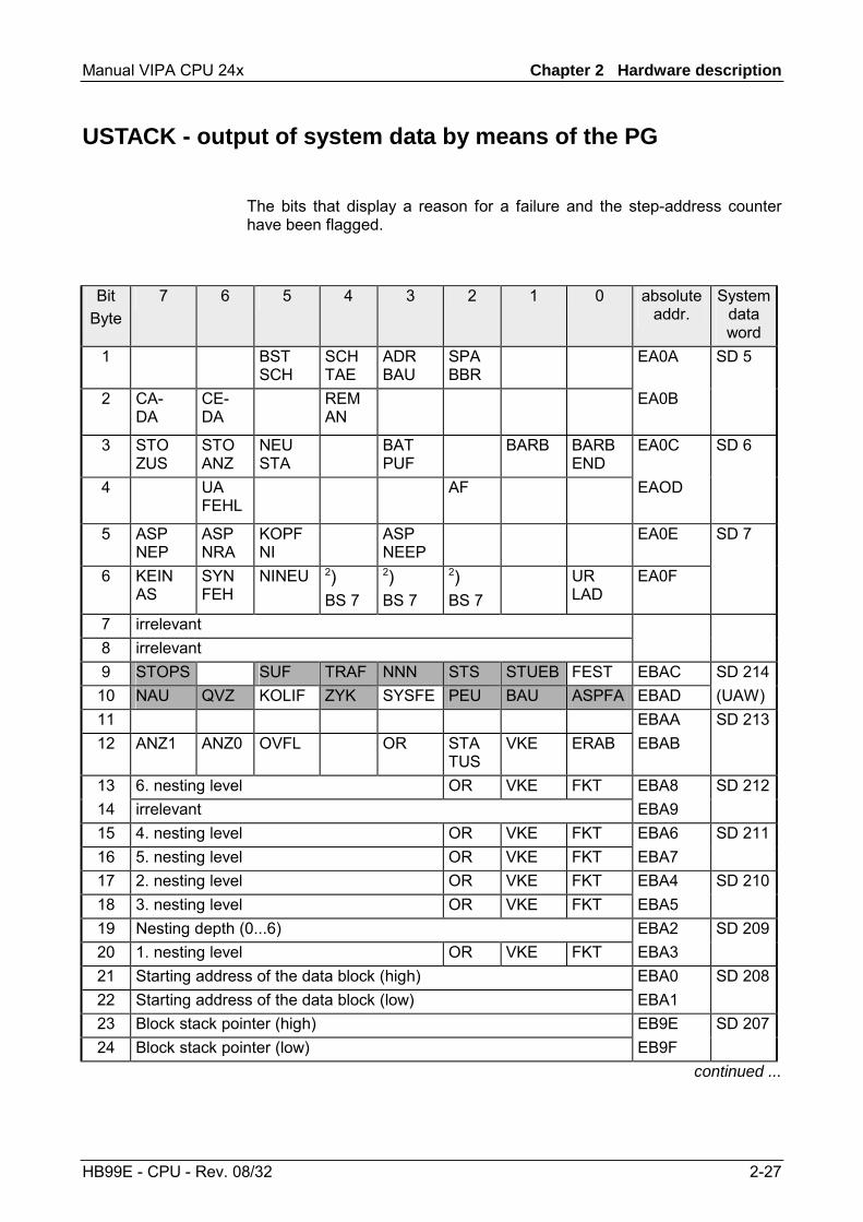
The bits that display a reason for a failure and the step-address counter have been flagged.
Bit Byte
7 6 5 4 3 2 1 0 absolute addr.
System data word
1 BST SCH
SCH TAE
ADR BAU
SPA BBR
EA0A SD 5
2 CA- DA
CE- DA
REM AN
EA0B
3 STO ZUS
STO ANZ
NEU STA
BAT PUF
BARB
BARB END
EA0C SD 6
4 UA FEHL
AF EAOD
5 ASP NEP
ASP NRA
KOPF NI
ASP NEEP
EA0E SD 7
6 KEIN AS
SYN FEH
NINEU 2) BS 7
2) BS 7
2) BS 7
UR LAD
EA0F
7 irrelevant 8 irrelevant 9 STOPS SUF TRAF NNN STS STUEB FEST EBAC SD 21410 NAU QVZ KOLIF ZYK SYSFE PEU BAU ASPFA EBAD (UAW) 11 EBAA SD 21312 ANZ1 ANZ0 OVFL OR STA
TUS VKE ERAB EBAB
13 6. nesting level OR VKE FKT EBA8 SD 21214 irrelevant EBA9 15 4. nesting level OR VKE FKT EBA6 SD 21116 5. nesting level OR VKE FKT EBA7 17 2. nesting level OR VKE FKT EBA4 SD 21018 3. nesting level OR VKE FKT EBA5 19 Nesting depth (0...6) EBA2 SD 20920 1. nesting level OR VKE FKT EBA3 21 Starting address of the data block (high) EBA0 SD 20822 Starting address of the data block (low) EBA1 23 Block stack pointer (high) EB9E SD 20724 Block stack pointer (low) EB9F
continued ...
Chapter 2 Hardware description Manual VIPA CPU 24x
2-28 HB99E - CPU - Rev. 08/32
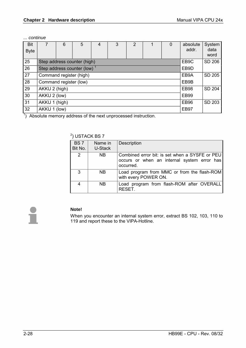
... continue Bit
Byte 7 6 5 4 3 2 1 0 absolute
addr. System
data word
25 Step address counter (high) EB9C SD 20626 Step address counter (low) 1 EB9D 27 Command register (high) EB9A SD 20528 Command register (low) EB9B 29 AKKU 2 (high) EB98 SD 20430 AKKU 2 (low) EB99 31 AKKU 1 (high) EB96 SD 20332 AKKU 1 (low) EB97
1) Absolute memory address of the next unprocessed instruction.
2) USTACK BS 7 BS 7
Bit No. Name in U-Stack
Description
2 NB Combined error bit: is set when a SYSFE or PEU occurs or when an internal system error has occurred.
3 NB Load program from MMC or from the flash-ROM with every POWER ON.
4 NB Load program from flash-ROM after OVERALL RESET.
Note! When you encounter an internal system error, extract BS 102, 103, 110 to 119 and report these to the VIPA-Hotline.

Manual VIPA CPU 24x Chapter 2 Hardware description
HB99E - CPU - Rev. 08/32 2-29
Abbreviations for control bits BSTSCH Block shift requested SCHTAE Block shift active function:
KOMP:AG ADRBAU Set up address lists SPABBR Compress canceled CA-DA Coupling flag output address list
exists CE-DE Coupling flag output address list
exists REMAN 0: all timers/counters and flags are
cleared by a reboot 1: only the second half of the timers, counters and flags are cleared by a reboot
STOZUS STOP-status (external request, e.g. from PG)
STOANZ STOP-indicator NEUSTA PLC rebooting BATPUF Backup battery tested O.K.
BARB Processing-check BARBEND Processing-check-end-of-request UAFEHL Bad interrupt indicator
AF Alarm enabled ASPNEP Memory module is EPROM ASPNRA Memory module is RAM KOPFNI block header can not be interpreted
ASPNEEP Memory module is EEPROM KEINAS No memory module SYNFEH Synchronization error (faulty
modules/blocks) NINEU Reboot not possible URLAD Bootstrap loader required
Other abbreviations: SD
System data (from address EA00h)
Abbreviations for control bits
Chapter 2 Hardware description Manual VIPA CPU 24x
2-30 HB99E - CPU - Rev. 08/32
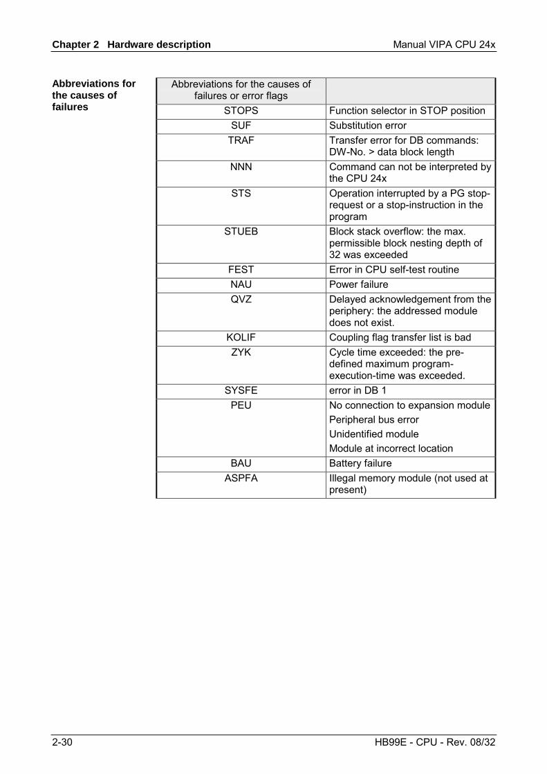
Abbreviations for the causes of failures or error flags
STOPS Function selector in STOP position SUF Substitution error
TRAF Transfer error for DB commands: DW-No. > data block length
NNN Command can not be interpreted by the CPU 24x
STS Operation interrupted by a PG stop-request or a stop-instruction in the program
STUEB Block stack overflow: the max. permissible block nesting depth of 32 was exceeded
FEST Error in CPU self-test routine NAU Power failure QVZ Delayed acknowledgement from the
periphery: the addressed module does not exist.
KOLIF Coupling flag transfer list is bad ZYK Cycle time exceeded: the pre-
defined maximum program-execution-time was exceeded.
SYSFE error in DB 1 PEU No connection to expansion module
Peripheral bus error Unidentified module Module at incorrect location
BAU Battery failure ASPFA Illegal memory module (not used at
present)
Abbreviations for the causes of failures

Manual VIPA CPU 24x Chapter 2 Hardware description
HB99E - CPU - Rev. 08/32 2-31
Other abbreviations UAW Interrupt indicator word
ANZ1/ANZ0 00:AKKU1 = 0 or 0 shifted 01: AKKU1 > 0 or 1 shifted 10: AKKU 1 < 0
OVFL arithmetic overflow (+ or -) ODER(OR) OR-flag
(set by "O" operation) STATUS STATUS of the operand of the most
recent binary operation. VKE Result of logical operation
ERAB Initial request KE1...KE6 Entry into bracket stack 1 to 6,
entered by U( and O( FKT 0: O(
1: U( BEF-REG Instruction register
SAZ Step address counter DB-ADR Data block address BST-STP Block stack pointer
NR Block number (OB, PB, FB, SB, DB)REL-SAZ Relative step address counter
Other abbreviations
Chapter 2 Hardware description Manual VIPA CPU 24x
2-32 HB99E - CPU - Rev. 08/32
Significance of the USTACK indicators
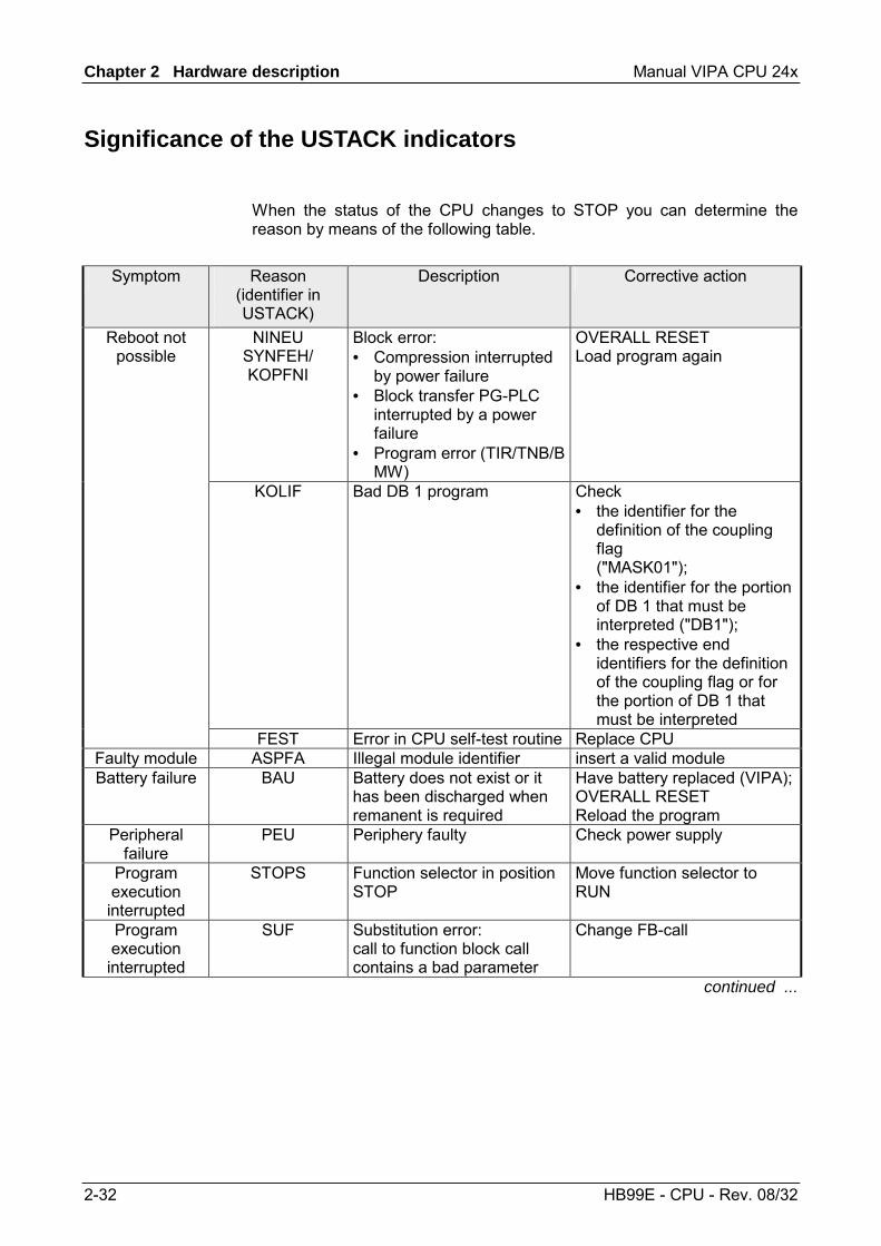
When the status of the CPU changes to STOP you can determine the reason by means of the following table.
Symptom Reason (identifier in USTACK)
Description Corrective action
Reboot not possible
NINEU SYNFEH/ KOPFNI
Block error: • Compression interrupted
by power failure • Block transfer PG-PLC
interrupted by a power failure
• Program error (TIR/TNB/B MW)
OVERALL RESET Load program again
KOLIF Bad DB 1 program Check • the identifier for the
definition of the coupling flag ("MASK01");
• the identifier for the portion of DB 1 that must be interpreted ("DB1");
• the respective end identifiers for the definition of the coupling flag or for the portion of DB 1 that must be interpreted
FEST Error in CPU self-test routine Replace CPU Faulty module ASPFA Illegal module identifier insert a valid module Battery failure BAU Battery does not exist or it
has been discharged when remanent is required
Have battery replaced (VIPA);OVERALL RESET Reload the program
Peripheral failure
PEU Periphery faulty Check power supply
Program execution interrupted
STOPS Function selector in position STOP
Move function selector to RUN
Program execution interrupted
SUF Substitution error: call to function block call contains a bad parameter
Change FB-call
continued ...
Manual VIPA CPU 24x Chapter 2 Hardware description
HB99E - CPU - Rev. 08/32 2-33
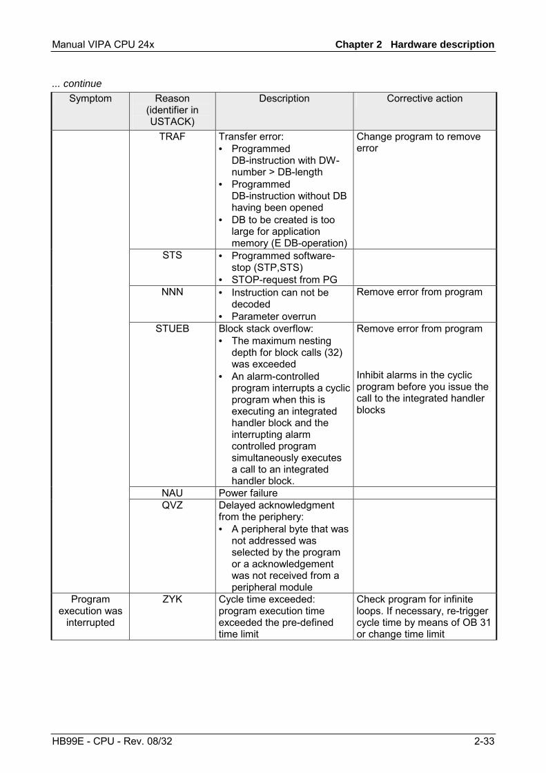
... continue Symptom Reason
(identifier in USTACK)
Description Corrective action
TRAF Transfer error: • Programmed
DB-instruction with DW-number > DB-length
• Programmed DB-instruction without DB having been opened
• DB to be created is too large for application memory (E DB-operation)
Change program to remove error
STS • Programmed software-stop (STP,STS)
• STOP-request from PG
NNN • Instruction can not be decoded
• Parameter overrun
Remove error from program
STUEB Block stack overflow: • The maximum nesting
depth for block calls (32) was exceeded
• An alarm-controlled program interrupts a cyclic program when this is executing an integrated handler block and the interrupting alarm controlled program simultaneously executes a call to an integrated handler block.
Remove error from program Inhibit alarms in the cyclic program before you issue the call to the integrated handler blocks
NAU Power failure QVZ Delayed acknowledgment
from the periphery: • A peripheral byte that was
not addressed was selected by the program or a acknowledgement was not received from a peripheral module
Program execution was
interrupted
ZYK Cycle time exceeded: program execution time exceeded the pre-defined time limit
Check program for infinite loops. If necessary, re-trigger cycle time by means of OB 31 or change time limit
Chapter 2 Hardware description Manual VIPA CPU 24x
2-34 HB99E - CPU - Rev. 08/32
Integrated FBs and OBs
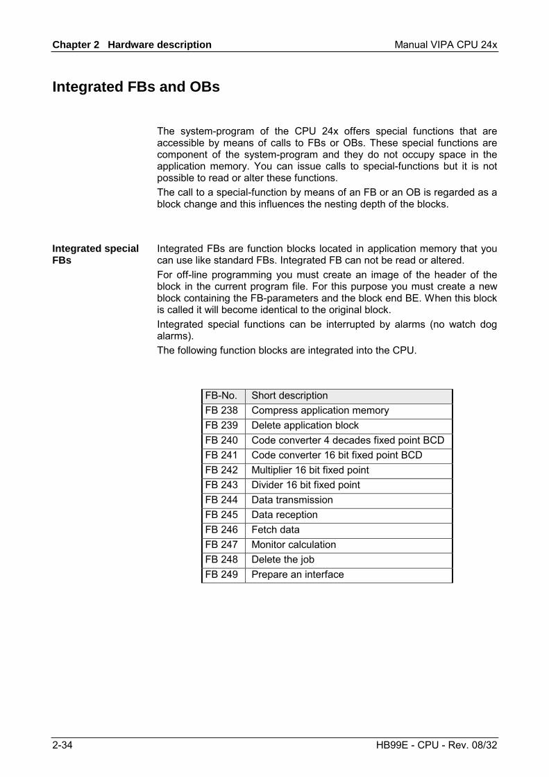
The system-program of the CPU 24x offers special functions that are accessible by means of calls to FBs or OBs. These special functions are component of the system-program and they do not occupy space in the application memory. You can issue calls to special-functions but it is not possible to read or alter these functions. The call to a special-function by means of an FB or an OB is regarded as a block change and this influences the nesting depth of the blocks.
Integrated FBs are function blocks located in application memory that you can use like standard FBs. Integrated FB can not be read or altered. For off-line programming you must create an image of the header of the block in the current program file. For this purpose you must create a new block containing the FB-parameters and the block end BE. When this block is called it will become identical to the original block. Integrated special functions can be interrupted by alarms (no watch dog alarms). The following function blocks are integrated into the CPU.
FB-No. Short description FB 238 Compress application memory FB 239 Delete application block FB 240 Code converter 4 decades fixed point BCD FB 241 Code converter 16 bit fixed point BCD FB 242 Multiplier 16 bit fixed point FB 243 Divider 16 bit fixed point FB 244 Data transmission FB 245 Data reception FB 246 Fetch data FB 247 Monitor calculation FB 248 Delete the job FB 249 Prepare an interface
Integrated special FBs

Manual VIPA CPU 24x Chapter 2 Hardware description
HB99E - CPU - Rev. 08/32 2-35
The integrated OBs are special functions that you can use by means of absolute or conditional OB-calls. At present the following special OBs are available in integrated form:
OB-No. Short description OB 31 Restart cycle time OB 160 Variable delay time OB 251 PID algorithm
A default DB 1 for the configuration of internal functions.
Note! A detailed description of the FBs, OBs, and of DB 1 is available in the chapter on "Integrated Blocks".
Integrated special OBs
DB 1
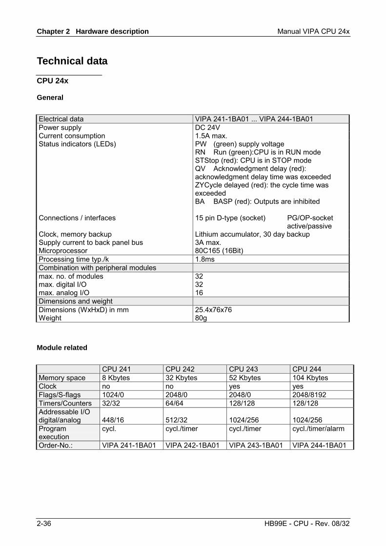
Chapter 2 Hardware description Manual VIPA CPU 24x
2-36 HB99E - CPU - Rev. 08/32
Technical data
Electrical data VIPA 241-1BA01 ... VIPA 244-1BA01 Power supply DC 24V Current consumption 1.5A max. Status indicators (LEDs) PW (green) supply voltage
RN Run (green):CPU is in RUN mode STStop (red): CPU is in STOP mode QV Acknowledgment delay (red): acknowledgment delay time was exceeded ZY Cycle delayed (red): the cycle time was exceeded BA BASP (red): Outputs are inhibited
Connections / interfaces 15 pin D-type (socket) PG/OP-socket active/passive
Clock, memory backup Lithium accumulator, 30 day backup Supply current to back panel bus 3A max. Microprocessor 80C165 (16Bit) Processing time typ./k 1.8ms Combination with peripheral modules max. no. of modules 32 max. digital I/O 32 max. analog I/O 16 Dimensions and weight Dimensions (WxHxD) in mm 25.4x76x76 Weight 80g
CPU 241 CPU 242 CPU 243 CPU 244 Memory space 8 Kbytes 32 Kbytes 52 Kbytes 104 Kbytes Clock no no yes yes Flags/S-flags 1024/0 2048/0 2048/0 2048/8192 Timers/Counters 32/32 64/64 128/128 128/128 Addressable I/O digital/analog
448/16
512/32
1024/256
1024/256
Program execution
cycl. cycl./timer cycl./timer cycl./timer/alarm
Order-No.: VIPA 241-1BA01 VIPA 242-1BA01 VIPA 243-1BA01 VIPA 244-1BA01
CPU 24x
General
Module related

Manual VIPA CPU 24x Chapter 2 Hardware description
HB99E - CPU - Rev. 08/32 2-37
Electrical data VIPA 241-2BT01/241-2BT10 ... VIPA244-2BT01/244-2BT10 Power supply via back panel bus Current consumption 380mA max. Isolation ≥ 500V AC Status indicator (LEDs) same as CPU 24x
additionally with PW supply voltage for CP Tx, Rx data transfer indicators
Connections/interfaces RJ45 for twisted pair Ethernet Ethernet interface Connector RJ45 Network topology Star topology with a max. of 2 hubs per segment Medium Twisted pair Rate of transfer 10 MBit / 10/100MBit (CPU 24x-2BT10) Overall length 100m max. per segment Combination with peripheral modules
max. digital I/O 32 max. analog I/O 16 Dimensions and weight Dimensions (WxHxD) in mm 50.8x76x76 Weight 80g
CPU 24x NET

Chapter 2 Hardware description Manual VIPA CPU 24x
2-38 HB99E - CPU - Rev. 08/32
Electrical data VIPA 241-2BP01 ... VIPA 244-2BP01 Power supply via back panel bus Current consumption 380mA max. Isolation ≥ 500V AC Status indicator (LEDs) same as CPU 24x
additionally with PW Power (green): 24V supply voltage ER Error (red): bus failure, slave failure RN Run (green): RUN mode indicator DE Data exchange (yellow): Profibus communication. IF Initialization error (red): incorrect configuration
Connections/interfaces 9-pin D-type (socket) Profibus connector Profibus interface Connector 9-polige D-type socket Network topology Linear bus, active bus termination at both ends, spur lines
are permitted. Medium Screened twisted pair cable. Depending on environment
screening may be omitted. Transfer rate 9.6 kBaud to 12 Mbaud Overall length 100m at 12 MBaud without repeater, up to 1000m with
repeater max. no. of stations 32 stations on every segment without repeater. Expandable
to 126 stations with repeater. Combination with peripheral modules
max. no. of slaves 125 max. no. of input bytes 256 max. no. of output bytes 256 Dimensions and weight Dimensions (WxHxD) in mm 50.8x76x76 Weight 80g
CPU 24x DP

Manual VIPA CPU 24x Chapter 3 CPU 24x deployment using I/O modules
HB99E - CPU - Rev. 08/32 3-1
Chapter 3 CPU 24x deployment using I/O modules
This chapter describes the deployment of the CPU 24x together with the peripheral modules of the System 200V. This information also applies to the CPU 24x NET and CPU 24x DP.
Topic Page Chapter 3 CPU 24x applications using I/O modules ........................... 3-1
Applications in conjunction with I/O modules ........................................ 3-2 Automatic assignment of peripheral addresses .................................... 3-3 Manual assignment of peripheral addresses ........................................ 3-5 Configuration of peripheral modules..................................................... 3-6
Note! This information is valid for all the CPU’s described in this manual since the back panel communications between the CPU and the peripheral modules is the same for all models of CPU!
Outline
Contents
Chapter 3 CPU 24x deployment using I/O modules Manual VIPA CPU 24x
3-2 HB99E - CPU - Rev. 08/32
Applications in conjunction with I/O modules
This information refers to modules that are installed on the same next to the CPU. Certain addresses must be allocated in the CPU to provide for specific addressing of the installed peripheral modules. Digital modules are generally addressed byte-wise and analog modules word-wise.
When the CPU is initialized it checks for all modules that are installed on the bus and assigns addresses to them in the peripheral area of the CPU. You can interact with these modules by means of read or writing access to the peripheral bytes.
Note! Please note that you read and write accesses to the same address interact with different modules. Digital and analog modules have separate addressing ranges. Digital modules: 0 ... 127 Analog modules: 128 ... 255
You can change the address allocation at any time by means of a DB1 reconfiguration. A user-friendly method for the address assignment and configuration of parameters is provided by the WinNCS of VIPA!
The signaling states of the lower addresses (0 ... 127) are also saved in a special memory area called the process image. The process image is divided into two portions: • process image of the inputs (PAE), • process image of the outputs (PAA).
General
Read or. write access via peripheral bytes
Allocating addressing ranges via DB1
Signaling states in the process image
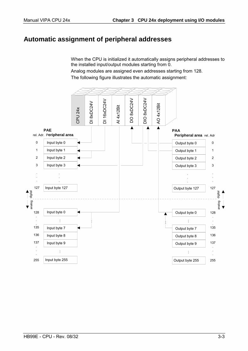
Manual VIPA CPU 24x Chapter 3 CPU 24x deployment using I/O modules
HB99E - CPU - Rev. 08/32 3-3
Automatic assignment of peripheral addresses
When the CPU is initialized it automatically assigns peripheral addresses to the installed input/output modules starting from 0. Analog modules are assigned even addresses starting from 128. The following figure illustrates the automatic assignment:
Input byte 00
1
2
3
.
.
.
127
.
.
.
128...
135
136
137...
255
rel. Adr. Peripheral area
CP
U 2
4x
DI 8
xDC
24V
DI 1
6xD
C24
V
AI 4
x12B
it
DO
8xD
C24
V
DIO
8xD
C24
V
AO
4x1
2Bit
anal
ogdi
gita
l
... ...
...
Input byte 1
Input byte 2
Input byte 3
Input byte 127
Input byte 0
Input byte 7
Input byte 8
Input byte 9
Input byte 255
Output byte 0
.
.
.
Peripheral area rel. Adr
...
...
Output byte 1
Output byte 2
Output byte 3
Output byte 127
Output byte 0
Output byte 7
Output byte 8
Output byte 9
Output byte 255
0
1
2
3
.
.
.
127
128...
135
136
137...
255
PAE PAA
anal
ogdi
gita
l
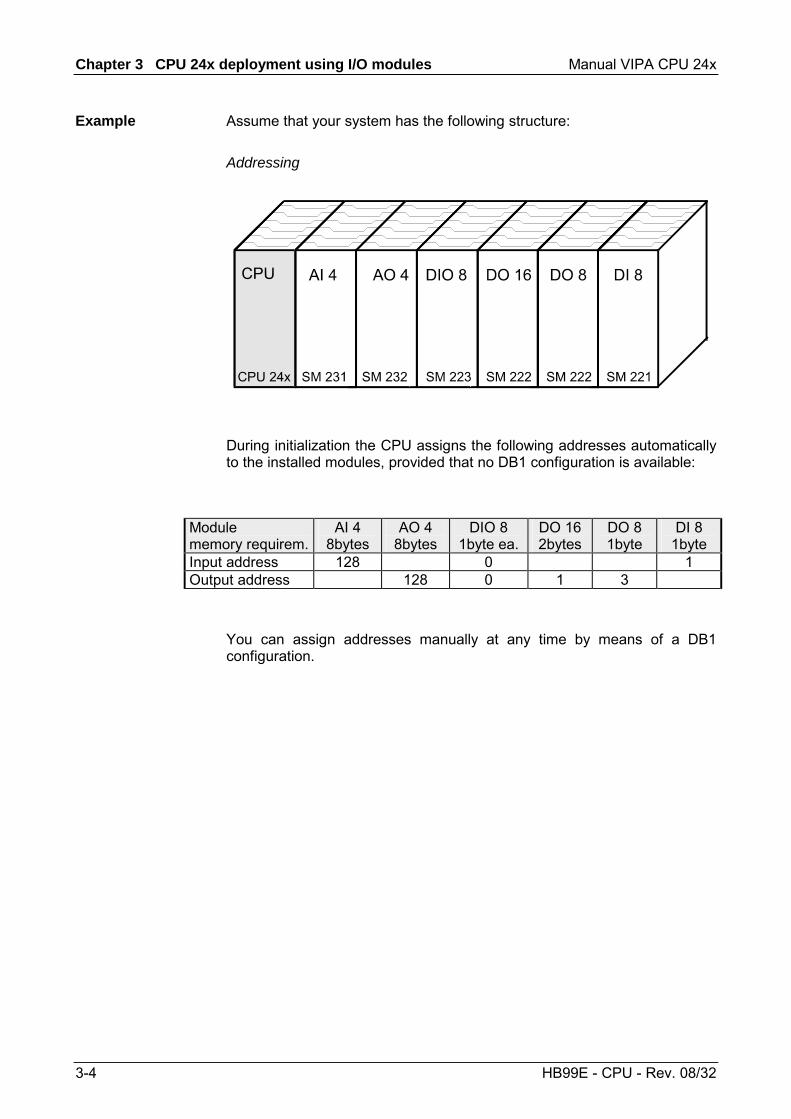
Chapter 3 CPU 24x deployment using I/O modules Manual VIPA CPU 24x
3-4 HB99E - CPU - Rev. 08/32
Assume that your system has the following structure: Addressing
During initialization the CPU assigns the following addresses automatically to the installed modules, provided that no DB1 configuration is available:
Module memory requirem.
AI 4 8bytes
AO 4 8bytes
DIO 8 1byte ea.
DO 16 2bytes
DO 8 1byte
DI 8 1byte
Input address 128 0 1 Output address 128 0 1 3
You can assign addresses manually at any time by means of a DB1 configuration.
Example
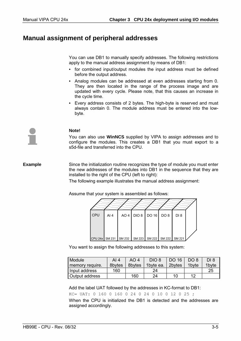
Manual VIPA CPU 24x Chapter 3 CPU 24x deployment using I/O modules
HB99E - CPU - Rev. 08/32 3-5
Manual assignment of peripheral addresses
You can use DB1 to manually specify addresses. The following restrictions apply to the manual address assignment by means of DB1: • for combined input/output modules the input address must be defined
before the output address. • Analog modules can be addressed at even addresses starting from 0.
They are then located in the range of the process image and are updated with every cycle. Please note, that this causes an increase in the cycle time.
• Every address consists of 2 bytes. The high-byte is reserved and must always contain 0. The module address must be entered into the low-byte.
Note! You can also use WinNCS supplied by VIPA to assign addresses and to configure the modules. This creates a DB1 that you must export to a s5d-file and transferred into the CPU.
Since the initialization routine recognizes the type of module you must enter the new addresses of the modules into DB1 in the sequence that they are installed to the right of the CPU (left to right): The following example illustrates the manual address assignment: Assume that your system is assembled as follows:
You want to assign the following addresses to this system: Module memory require.
AI 4 8bytes
AO 4 8bytes
DIO 8 1byte ea.
DO 16 2bytes
DO 8 1byte
DI 8 1byte
Input address 160 24 25 Output address 160 24 10 12 Add the label UAT followed by the addresses in KC-format to DB1: KC= UAT: 0 160 0 160 0 24 0 24 0 10 0 12 0 25 ;
When the CPU is initialized the DB1 is detected and the addresses are assigned accordingly.
Example

Chapter 3 CPU 24x deployment using I/O modules Manual VIPA CPU 24x
3-6 HB99E - CPU - Rev. 08/32
Configuration of peripheral modules
Directly installed modules as for instance analog modules can be provided with up to 16 bytes of configuration data from the CPU. In DB1 you can specify a configuration in hex-format for every plug-in location. A label is assigned to every plug-in location: Plug-in location (0...31) → Label (P00...P31) CPU-firmware revision up to V1.09 Plug-in location (1...32) → Label (P01...P32) CPU-firmware revision higher V1.09
Note! With CPU-firmware revision higher than V1.09 the plug-in locations are -number starting from 1.
The version of your CPU 24x is available from the "System information" provided by your programming software, e.g. MC5 of VIPA. This consists of the following sequence:
V 1 . 07
Configuration depending on CPU-firmware revision
Determining the version
AG software revision level PG - AS software revision level

Manual VIPA CPU 24x Chapter 3 CPU 24x deployment using I/O modules
HB99E - CPU - Rev. 08/32 3-7
The following example explains the configuration of two analog modules: Example Let us assume your system is assembled as follows:
CPU AI 4 AO 4
SM 231 SM 232CPU 24x
AI 4x16Bit Multi-input- no diagnostic alarm- channel 0: voltage interface (-10 ... +10V)- channel 1: current interface (4 ... 20mA)- channel 2: Pt100 (-200 ... 850°C)- channel 3: no interface- default options
AO 4x12Bit Multi-output- no diagnostic alarm- channel 0: current output (4 ... 20mA)- channel 1: voltage output (1 ... 5V)- channel 2: no output
This results in the following configuration for the two analog modules:
Diagnostic alarm byte
reserved
Function no. channel 0
Function no. channel 1
Function no. channel 2
Function no. channel 3
Option byte channel 0
Option byte channel 1
Option byte channel 2
Option byte channel 3
AI 4x16Bit Multi-input
Byte 0
Byte 1
Byte 2
Byte 3
Byte 4
Byte 5
Byte 6
Byte 7
Byte 8
Byte 9
00h
00h
2Bh
2Dh
02h
00h
00h
00h
00h
00h
Parameter areas :
Diagnostic alarm byte
reserved
Function byte channel 0
Function byte channel 1
Function byte channel 2
Function byte channel 3
AO 4x12Bit Multi-output
Byte 0
Byte 1
Byte 2
Byte 3
Byte 4
Byte 5
00h
00h
04h
02h
00h
01h
Add the KC-formatted (string) entry Pxx (where xx is the plug-in location) followed by the hex parameter bytes to DB1. Separate these entries by a semicolon:
KC= P01: 00 00 2B 2D 02 00 00 00 00 00 ;
P02: 00 00 04 02 00 01 ;
Every label, every number and every semicolon must be followed by a space!
Example

Chapter 3 CPU 24x deployment using I/O modules Manual VIPA CPU 24x
3-8 HB99E - CPU - Rev. 08/32
Manual VIPA CPU 24x Chapter 4 CPU 24x-2BT10 deployment
HB99E - CPU - Rev. 08/32 4-1
Chapter 4 CPU 24x-2BT10 deployment
The following chapter describes the deployment of the Net-CPU 24x2BT10 NET and the TCP/IP communication procedure.
Topic Page Chapter 4 CPU 24x-2BT10 deployment........................................... 4-1
Industrial Ethernet in automation .......................................................... 4-2 ISO/OSI reference model ..................................................................... 4-3 Principles.............................................................................................. 4-6 Protocols .............................................................................................. 4-7 IP address and subnet........................................................................ 4-10 Network planning................................................................................ 4-12 Communication possibilities of the CP................................................ 4-14 Programming Communication Connections........................................ 4-16 SEND/RECEIVE with PLC program ................................................... 4-23 Coupling to other systems .................................................................. 4-27 NCM diagnostic – Help for error diagnostic ........................................ 4-30
Outline
Contents
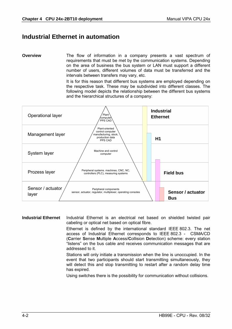
Chapter 4 CPU 24x-2BT10 deployment Manual VIPA CPU 24x
4-2 HB99E - CPU - Rev. 08/32
Industrial Ethernet in automation
The flow of information in a company presents a vast spectrum of requirements that must be met by the communication systems. Depending on the area of business the bus system or LAN must support a different number of users, different volumes of data must be transferred and the intervals between transfers may vary, etc. It is for this reason that different bus systems are employed depending on the respective task. These may be subdivided into different classes. The following model depicts the relationship between the different bus systems and the hierarchical structures of a company:
Operational layer
Management layer
System layer
Prozess layer
Sensor / actuatorlayer
Field bus
Sensor / actuatorBus
H1
IndustrialEthernetPlant
computerPPS CAD
Plant-orientedcontrol computer
manufacturing, stock,production data
PPS CAD
Machine and controlcomputer
Peripheral systems. machines, CNC, NC,controllers (PLC), measuring systems
Peripheral componentssensor, actuator, regulator, multiplexer, operating consoles
Industrial Ethernet is an electrical net based on shielded twisted pair cabeling or optical net based on optical fibre. Ethernet is defined by the international standard IEEE 802.3. The net access of Industrial Ethernet corresponds to IEEE 802.3 - CSMA/CD (Carrier Sense Multiple Access/Collision Detection) scheme: every station “listens” on the bus cable and receives communication messages that are addressed to it. Stations will only initiate a transmission when the line is unoccupied. In the event that two participants should start transmitting simultaneously, they will detect this and stop transmitting to restart after a random delay time has expired. Using switches there is the possibility for communication without collisions.
Overview
Industrial Ethernet
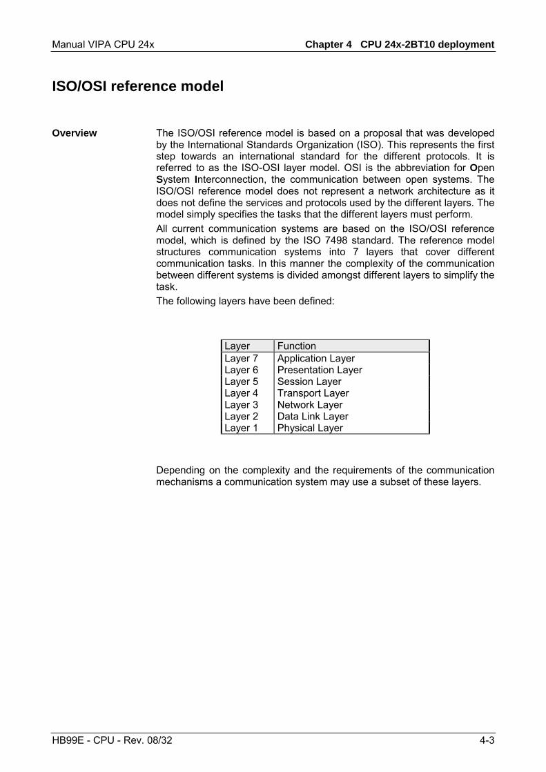
Manual VIPA CPU 24x Chapter 4 CPU 24x-2BT10 deployment
HB99E - CPU - Rev. 08/32 4-3
ISO/OSI reference model
The ISO/OSI reference model is based on a proposal that was developed by the International Standards Organization (ISO). This represents the first step towards an international standard for the different protocols. It is referred to as the ISO-OSI layer model. OSI is the abbreviation for Open System Interconnection, the communication between open systems. The ISO/OSI reference model does not represent a network architecture as it does not define the services and protocols used by the different layers. The model simply specifies the tasks that the different layers must perform. All current communication systems are based on the ISO/OSI reference model, which is defined by the ISO 7498 standard. The reference model structures communication systems into 7 layers that cover different communication tasks. In this manner the complexity of the communication between different systems is divided amongst different layers to simplify the task. The following layers have been defined:
Layer Function Layer 7 Application Layer Layer 6 Presentation Layer Layer 5 Session Layer Layer 4 Transport Layer Layer 3 Network Layer Layer 2 Data Link Layer Layer 1 Physical Layer
Depending on the complexity and the requirements of the communication mechanisms a communication system may use a subset of these layers.
Overview
Chapter 4 CPU 24x-2BT10 deployment Manual VIPA CPU 24x
4-4 HB99E - CPU - Rev. 08/32
Layer 1 Bit communication layer (physical layer) The bit communication layer (physical layer) is concerned with the transfer of data bits via the communication channel. This layer is therefore responsible for the mechanical, electrical and the procedural interfaces and the physical communication medium located below the bit communication layer: • Which voltage represents a logical 0 or a 1? • The minimum time that the voltage is present to be recognized as a bit. • The pin assignment of the respective interface. Layer 2 Security layer (data link layer) This layer performs error-checking functions for bit strings transferred between two communicating partners. This includes the recognition and correction or flagging of communication errors and flow control functions. The security layer (data link layer) converts raw communication data into a sequence of frames. This is where frame limits are inserted on the transmitting side and where the receiving side detects them. These limits consist of special bit patterns that are inserted at the beginning and at the end of every frame. The security layer often also incorporates flow control and error detection functions. The data security layer is divided into two sub-levels, the LLC and the MAC level. The MAC (Media Access Control) is the lower level and controls how senders are sharing a single transmit channel. The LLC (Logical Link Control) is the upper level that establishes the connection for transferring the data frames from one device into the other. Layer 3 Network layer The network layer is an agency layer. Business of this layer is to control the exchange of binary data between stations that are not directly connected. It is responsible for the logical connections of layer 2 communication. Layer 3 supports the identification of the single network addresses and the establishing and disconnecting of logical communication channels. Additionally, layer 3 manages the prior transfer of data and the error processing of data packets. IP (Internet Protocol) is based on Layer 3. Layer 4 Transport layer Layer 4 connects the network structures with the structures of the higher levels by dividing the messages of higher layers into segments and pass them on to the network layer. Hereby, the transport layer converts the transport addresses into network addresses. Common transport protocols are: TCP, SPX, NWLink and NetBEUI.
Layers
Manual VIPA CPU 24x Chapter 4 CPU 24x-2BT10 deployment
HB99E - CPU - Rev. 08/32 4-5
Layer 5 Session layer The session layer is also called the communication control layer. It relieves the communication between service deliverer and the requestor by establishing and holding the connection if the transport system has a short time fail out. At this layer, logical users may communicate via several connections at the same time. If the transport system fails, a new connection is established if needed. Additionally this layer provides methods for control and synchronization tasks. Layer 6 Presentation layer This layer manages the presentation of the messages, when different network systems are using different representations of data. Layer 6 converts the data into a format that is acceptable for both communication partners. Here compression/decompression and encrypting/decrypting tasks are processed. This layer is also called interpreter. A typical use of this layer is the terminal emulation. Layer 7 Application layer The application layer is the link between the user application and the network. The tasks of the application layer include the network services like file, print, message, data base and application services as well as the according rules. This layer is composed from a series of protocols that are permanently expanded following the increasing needs of the user.
Layers continued...
Chapter 4 CPU 24x-2BT10 deployment Manual VIPA CPU 24x
4-6 HB99E - CPU - Rev. 08/32
Principles
A network res. LAN (local area network) provides a link between different stations that enables them to communicate with each other. Network stations consist of PCs, IPCs, TCP/IP adapters, etc. Network stations are separated by a minimum distance and connected by means of a network cable. The combination of network stations and the network cable represent a complete segment. All the segments of a network form the Ethernet (physics of a network).
In the early days of networking the Triaxial- (yellow cable) or thin Ethernet cable (Cheapernet) was used as communication medium. This has been superseded by the twisted-pair network cable due to its immunity to interference. The CPU 24xNET module has a twisted-pair connector. The twisted-pair cable consists of 8 cores that are twisted together in pairs. Due to these twists this system is provides an increased level of immunity to electrical interference. For linking please use twisted pair cable which at least corresponds to the category 5. Where the coaxial Ethernet networks are based on a bus topology the twisted-pair network is based on a point-to-point scheme. The network that may be established by means of this cable has a star topology. Every station is connected to the star coupler (hub/switch) by means of a separate cable. The hub/switch provides the interface to the Ethernet.
The hub is the central element that is required to implement a twisted-pair Ethernet network. It is the job of the hub to regenerate and to amplify the signals in both directions. At the same time it must have the facility to detect and process segment wide collisions and to relay this information. The hub is not accessible by means of a separate network address since it is not visible to the stations on the network. A hub has provisions to interface to Ethernet or to another hub res. switch.
A switch also is a central element for realizing Ethernet on Twisted Pair. Several stations res. hubs are connected via a switch. Afterwards they are able to communicate with each other via the switch without interfering the network. An intelligent hardware analyzes the incoming telegrams of every port of the switch and passes them collision free on to the destination stations of the switch. A switch optimizes the bandwidth in every connected segment of a network. Switches enable exclusive connections between the segments of a network changing at request.
Network (LAN)
Twisted Pair
Hub (repeater)
Switch
Manual VIPA CPU 24x Chapter 4 CPU 24x-2BT10 deployment
HB99E - CPU - Rev. 08/32 4-7
Protocols
Protocols define a set of instructions or standards that enable computer to establish communication connections and exchange information as error free as possible. A commonly established protocol for the standardization of the complete computer communication is the so-called ISO/OSI layer model, a model based upon seven layers with rules for the usage of hardware and software (see ISO/OSI reference model above). The CPU 24xNET from VIPA uses the following protocols • TCP/IP • UDP • RFC1006 (ISO-ON-TCP) The protocols are described in the following:
TCP/IP protocols are available on all major systems. At the bottom end this applies to simple PCs, through to the typical mini-computer up to mainframes. For the wide spread of internet accesses and connections, TCP/IP is often used to assemble heterogeneous system pools. TCP/IP, standing for Transmission Control Protocol and Internet Protocol, collects a various range of protocols and functions. TCP and IP are only two of the protocols required for the assembly of a complete architecture. The application layer provides programs like "FTP" and "Telnet" for the PC. The application layer of the Ethernet part of the CPU 24xNET is defined with the user application using the standard handling blocks. These user applications use the transport layer with the protocols TCP and UDP for the data transfer, which themselves communicate via the IP protocol with the internet layer.
Overview
TCP/IP
Chapter 4 CPU 24x-2BT10 deployment Manual VIPA CPU 24x
4-8 HB99E - CPU - Rev. 08/32
The Internet protocol covers the network layer (Layer 3) of the ISO/OSI layer model. The purpose of IP is to send data packages from on PC to another passing several other PCs. These data packages are referred to as datagrams. The IP doesn't guarantee the correct sequence of the datagrams nor the delivery at the receiver. For the unambiguous identification between sender and receiver at IPv4 32Bit addresses (IP addresses) are used that are written as four octets (exactly 8Bit), e.g. 172.16.192.11. These Internet addresses are defined and assigned worldwide from the DDN network (Defense Department Network), thus every user may communicate with all other TCP/IP users. One part of the address specifies the network; the rest serves the identification of the participants inside the network. The boarder between the network and the host part is variable and depends on the size of the network. To save IP addresses, so called NAT router are used that have one official IP address and cover the network. Then the network can use any IP address.
The TCP (Transmission Control Protocol) bases directly on the IP and thus covers the transport layer (layer 4) of the OSI layer model. TCP is a connection orientated end-to-end protocol and serves the logic connection between two partners. TCP guarantees the correct sequence and reliability of the data transfer. Therefore you need a relatively large protocol overhead that slows down the transfer speed. Every datagram gets a header of at least 20Byte. This header also contains a sequence number identifying the series. This has the consequence that the single datagrams may reach the destination on different ways through the network. Using TCP connections, the whole data length is not transmitted. This means that the recipient has to know how many bytes belong to a message. To transfer data with variable length you may begin the user data with the length information and evaluate this at the counter station. • Besides of the IP address ports are used for the addressing. A port
address should be within the range of 2000...65535. Partner and local ports may only be identical at one connection.
• Independently of the used protocol, the PLC needs the handling blocks FB 234 (SEND1) and FB 235 (RECV1) for data transfer.
IP
TCP
Properties

Manual VIPA CPU 24x Chapter 4 CPU 24x-2BT10 deployment
HB99E - CPU - Rev. 08/32 4-9
The UDP (User Datagram Protocol) is a connection free transport protocol. It has been defined in the RFC768 (Request for Comment). Compared to TCP, it has much fewer characteristics. The addressing happens via port numbers. UDP is a fast unsafe protocol for it doesn't care about missing data packages nor about their sequence.
The TCP transport service works stream orientated. This means that data packages assembled by the user not necessarily have to receive the partner in the same packaging. Depending on the data amount, packages may though come in in the correct sequence but differently packed. This causes that the recipient may not recognize the package borders anymore. For example you may send 2x 10Byte packages but the counter station receives them as 20Byte package. But for most of the applications the correct packaging is important. Due to this you need another protocol above TCP. This purpose is defined in the protocol RFC1006. The protocol definition describes the function of an ISO transport interface (ISO 8072) basing upon the transport interface TCP (RFC793). The basic protocol of RFC1006 is nearly identical to TP0 (Transport Protocol, Class 0) in ISO 8073. For RFC1006 is run as protocol for TCP, the decoding takes place in the data section of the TCP package.
• In contrast to TCP here the receipt of one telegram is confirmed. • Instead of ports TSAPs are used for the addressing besides of the IP
address. The TSAP length may be 1 ... 16Byte. The entry may happen in ASCII or Hex format. Foreign and local TSAPs may only be identical at 1 connection.
• Independently of the used protocol, the PLC needs the handling blocks FB 234 (SEND1) and FB 235 (RECV1) for data transfer.
• Contrary to TCP different telegram lengths can be received using RFC1006.
UDP
ISO-on-TCP RFC1006
Properties
Chapter 4 CPU 24x-2BT10 deployment Manual VIPA CPU 24x
4-10 HB99E - CPU - Rev. 08/32
IP address and subnet
Industrial Ethernet exclusively supports IPv4. At IPv4 the IP address is a 32Bit address that must be unique within the network and consists of 4 numbers that are separated by a dot. Every IP address is a combination of a Net-ID and a Host-ID and its structure is as follows: xxx.xxx.xxx.xxx Range: 000.000.000.000 to 255.255.255.255 The network administrator also defines IP addresses.
The Network-ID identifies a network res. a network controller that administrates the network. The Host-ID marks the network connections of a participant (host) to this network.
The Host-ID can be further divided into a Subnet-ID and a new Host-ID by using a bit for bit AND assignment with the Subnet mask. The area of the original Host-ID that is overwritten by 1 of the Subnet mask becomes the Subnet-ID; the rest is the new Host-ID.
Subnet mask binary all "1" binary all "0" IPv4 address Net-ID Host-ID Subnet mask and IPv4 address Net-ID Subnet-ID new Host-ID
A TCP-based communication via point-to-point, hub or switch connection is only possible between stations with identical Network-ID and Subnet-ID! Different area must be connected with a router. The subnet mask allows you to sort the resources following your needs. This means e.g. that every department gets an own subnet and thus does not interfere another department.
At the first start-up the CP does not have any IP address. The IP address may be assigned with the FB 236 (IP_CONFIG) by means of a configuration data block. Besides the IP address data the connections were also be configured, here.
IP address structure
Net-ID Host-ID
Subnet mask
Subnet
Address at first start-up
Manual VIPA CPU 24x Chapter 4 CPU 24x-2BT10 deployment
HB99E - CPU - Rev. 08/32 4-11
For IPv4 addresses there are five address formats (class A to class E) that are all of a length of 4 Byte = 32 Bit. Class A 0 Network-ID
(1+7 bit) Host-ID (24 bit)
Class B 10 Network-ID (2+14 bit) Host-ID (16 bit) Class C 110 Network-ID (3+21 bit) Host-ID (8 bit)Class D 1110 Multicast group Class E 11110 Reserved
The classes A, B and C are used for individual addresses, class D for multicast addresses and class E is reserved for special purposes. The address formats of the 3 classes A, B, C are only differing in the length of Network-ID and Host-ID. To build up private IP-Networks within the Internet, RFC1597/1918 reserves the following address areas:
Network class
Start IP End IP Standard subnet mask
A 10.0.0.0 10.255.255.255 255.0.0.0 B 172.16.0.0 172.31.255.255 255.255.0.0 C 192.168.0.0 192.168.255.255 255.255.255.0 (The Host-ID is underlined.)
These addresses can be used as net-ID by several organizations without causing conflicts, for these IP addresses are neither assigned in the Internet nor are routed in the Internet.
Some Host-IDs are reserved for special purposes. Host-ID = 0 Identifier of this network, reserved! Host-ID = maximum (binary complete 1) Broadcast address of this network Note! Never choose an IP address with Host-ID=0 or Host-ID=maximum! (e.g. for class B with subnet mask = 255.255.0.0, the "172.16.0.0" is reserved and the "172.16.255.255" is occupied as local broadcast address for this network.)
Address classes
Private IP networks
Reserved Host-Ids
Chapter 4 CPU 24x-2BT10 deployment Manual VIPA CPU 24x
4-12 HB99E - CPU - Rev. 08/32
Network planning
The applicable rules and regulations have to be satisfied in order to establish reliable communications between the different stations. These agreements define the form of the data protocol, the method of bus access and other principles that are important for reliable communications. The VIPA CPU 24x-2BT10 was developed in accordance with the standards defined by ISO. International and national committees have defined the following standards and guidelines for networking technologies:
ANSI American National Standards Institute The ANSI X3T9.5 standard currently defines the provisions for high-speed LANs (100 MB/s) based on fiber optic technology. (FDDI) Fiber Distributed Data Interface.
CCITT Committee Consultative Internationale de Telephone et Telegraph. Amongst others, this advisory committee has produced the provisions for the connection of industrial networks (MAP) to office networks (TOP) on Wide Area Networks (WAN).
ECMA European Computer Manufacturers Association. Has produced various MAP and TOP standards.
EIA Electrical Industries Association (USA) This committee has issued standard definitions like RS-232 (V.24) and RS-511.
IEC International Electrotechnical Commission. Defines certain special standards, e.g. for the Field Bus.
ISO International Organization for Standardization. This association of national standards organizations developed the OSI-model (ISO/TC97/SC16). It provides the framework for the standardization of data communications. ISO standards are included in different national standards like for example UL and DIN.
IEEE Institute of Electrical and Electronic Engineers (USA). The project-group 802 determines LAN-standards for transfer rates of 1 to 1000MB/s. IEEE standards often form the basis for ISO-standards, e.g. IEEE 802.3 = ISO 8802.3.
Standards and guidelines
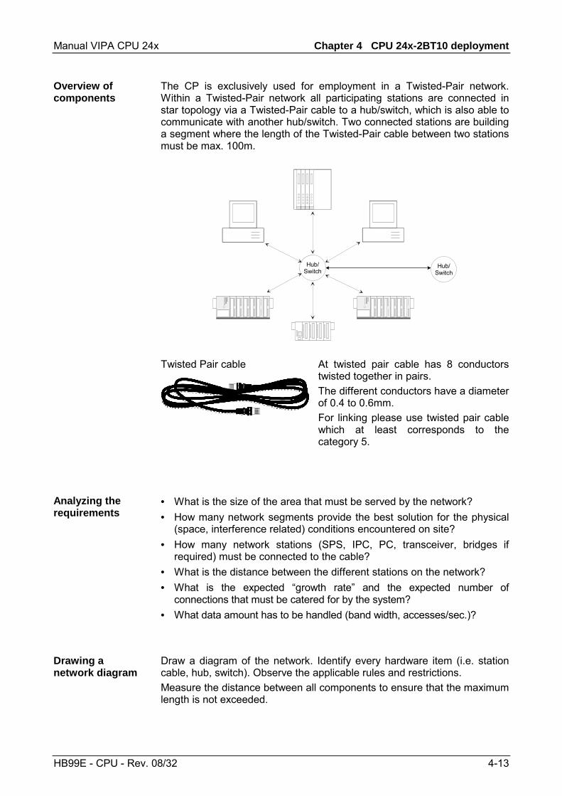
Manual VIPA CPU 24x Chapter 4 CPU 24x-2BT10 deployment
HB99E - CPU - Rev. 08/32 4-13
The CP is exclusively used for employment in a Twisted-Pair network. Within a Twisted-Pair network all participating stations are connected in star topology via a Twisted-Pair cable to a hub/switch, which is also able to communicate with another hub/switch. Two connected stations are building a segment where the length of the Twisted-Pair cable between two stations must be max. 100m.
Hub/Switch
Hub/Switch
Twisted Pair cable At twisted pair cable has 8 conductors
twisted together in pairs. The different conductors have a diameter of 0.4 to 0.6mm. For linking please use twisted pair cable which at least corresponds to the category 5.
• What is the size of the area that must be served by the network? • How many network segments provide the best solution for the physical
(space, interference related) conditions encountered on site? • How many network stations (SPS, IPC, PC, transceiver, bridges if
required) must be connected to the cable? • What is the distance between the different stations on the network? • What is the expected “growth rate” and the expected number of
connections that must be catered for by the system? • What data amount has to be handled (band width, accesses/sec.)?
Draw a diagram of the network. Identify every hardware item (i.e. station cable, hub, switch). Observe the applicable rules and restrictions. Measure the distance between all components to ensure that the maximum length is not exceeded.
Overview of components
Analyzing the requirements
Drawing a network diagram
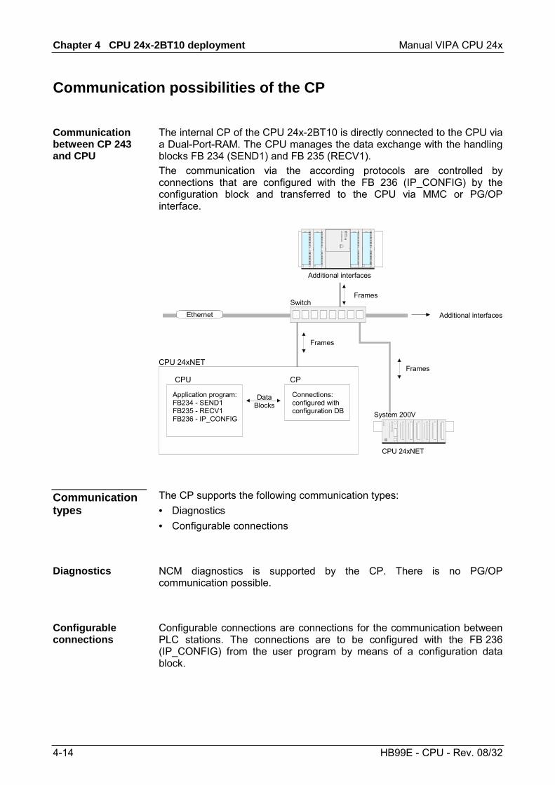
Chapter 4 CPU 24x-2BT10 deployment Manual VIPA CPU 24x
4-14 HB99E - CPU - Rev. 08/32
Communication possibilities of the CP
The internal CP of the CPU 24x-2BT10 is directly connected to the CPU via a Dual-Port-RAM. The CPU manages the data exchange with the handling blocks FB 234 (SEND1) and FB 235 (RECV1). The communication via the according protocols are controlled by connections that are configured with the FB 236 (IP_CONFIG) by the configuration block and transferred to the CPU via MMC or PG/OP interface.
CPCPU
Connections:configured withconfiguration DB
Ethernet
System 200V
CPU 24xNET
Frames
CPU 24xNET
Ethernet Additional interfaces
DataBlocks
Frames
Frames
Switch
Application program:FB234 - SEND1FB235 - RECV1FB236 - IP_CONFIG
Additional interfaces
The CP supports the following communication types: • Diagnostics • Configurable connections
NCM diagnostics is supported by the CP. There is no PG/OP communication possible.
Configurable connections are connections for the communication between PLC stations. The connections are to be configured with the FB 236 (IP_CONFIG) from the user program by means of a configuration data block.
Communication between CP 243 and CPU
Communication types
Diagnostics
Configurable connections
Manual VIPA CPU 24x Chapter 4 CPU 24x-2BT10 deployment
HB99E - CPU - Rev. 08/32 4-15
In the following the functions are listed that are supported by the CP of the CPU 24x-2BT10:
Function Property Maximum number of productive connections
64
TCP connections SEND, RECEIVE, FETCH PASSIVE, WRITE PASSIVE Connection establishment active and passive, supports unspecified connection partner
ISO-on-TCP connections (RFC1006)
SEND, RECEIVE, FETCH PASSIVE, WRITE PASSIVE Connection establishment active and passive, supports unspecified connection partner
UDP connections SEND and RECEIVE The transfer of the telegrams is not acknowledged, i.e. the loss of messages is not recognized by the send block.
UDP Broadcast connection
SEND
UDP Multicast connection
SEND and RECEIVE (max. 16 multicast circles)
Data block length max. 64kByte (max. 2kByte at UDP) VIPA handling blocks For connection commands at the PLC:
FB 234 (SEND1) / FB 235 (RECV1) / FB 236 (IP_CONFIG)
Function Property Maximum number of PG/OP connections
-
Diagnostic Supports NCM diagnostics Search within network - 10/100MBit Switch happens automatically
Function overview
Configurable connections
PG connections and diagnostic

Chapter 4 CPU 24x-2BT10 deployment Manual VIPA CPU 24x
4-16 HB99E - CPU - Rev. 08/32
Programming Communication Connections
The configuration of the CP exclusively takes place with the FB 236 (IP_CONFIG). This allows a flexible transfer of data blocks with configuration data to the CP. To process the connection commands at the PLC FB 234 (SEND1) and FB 235 (RECV1) are to be called by the user program. By including these blocks into the cycle block OB1 you may send and receive data cyclically.
Configuration data for communication connections may be transferred to the CP by the FB 236 (IP_CONFIG) called in the user program.
FB 236 IP_CONF
Connection 1
System data for CP
Connection 2
Connection 64
.
.
.
Configuration datatransfered to the CP
The configuration DB may be loaded into the CP at any time. Attention! As soon as the user program transfers the connection data via FB 236 IP_CONFIG, the CPU switches the CP briefly to STOP. The CP accepts the system data (including IP address) and the new connection data and processes it during startup (RUN).
Overview
Principle
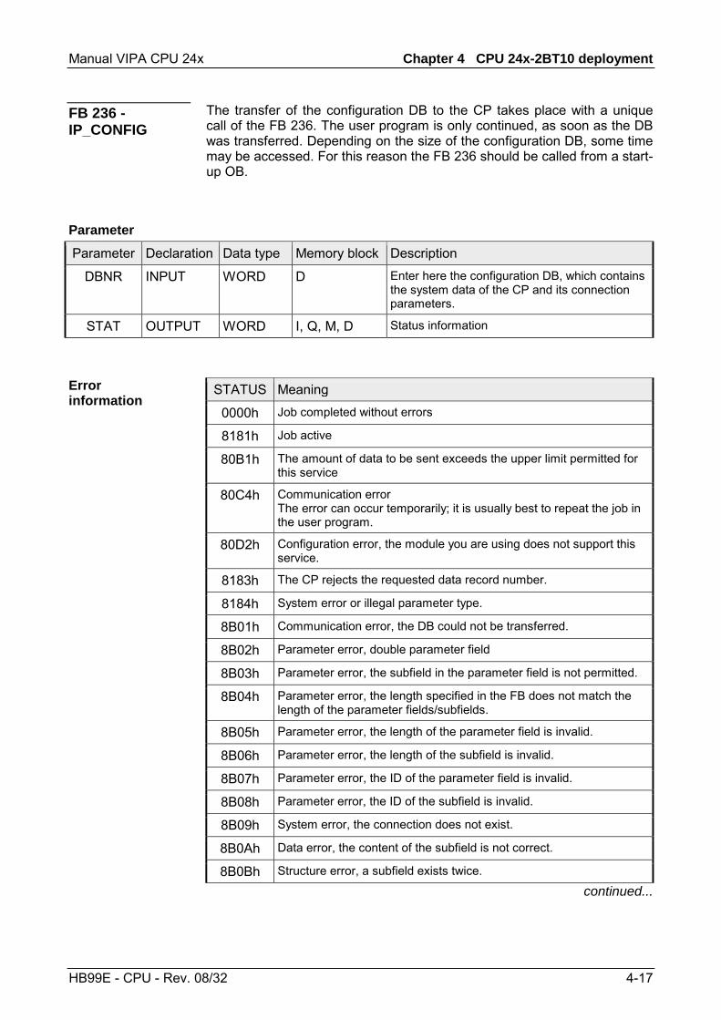
Manual VIPA CPU 24x Chapter 4 CPU 24x-2BT10 deployment
HB99E - CPU - Rev. 08/32 4-17
The transfer of the configuration DB to the CP takes place with a unique call of the FB 236. The user program is only continued, as soon as the DB was transferred. Depending on the size of the configuration DB, some time may be accessed. For this reason the FB 236 should be called from a start-up OB.
Parameter Declaration Data type Memory block Description
DBNR INPUT WORD D Enter here the configuration DB, which contains the system data of the CP and its connection parameters.
STAT OUTPUT WORD I, Q, M, D Status information
STATUS Meaning
0000h Job completed without errors
8181h Job active
80B1h The amount of data to be sent exceeds the upper limit permitted for this service
80C4h Communication error The error can occur temporarily; it is usually best to repeat the job in the user program.
80D2h Configuration error, the module you are using does not support this service.
8183h The CP rejects the requested data record number.
8184h System error or illegal parameter type.
8B01h Communication error, the DB could not be transferred.
8B02h Parameter error, double parameter field
8B03h Parameter error, the subfield in the parameter field is not permitted.
8B04h Parameter error, the length specified in the FB does not match the length of the parameter fields/subfields.
8B05h Parameter error, the length of the parameter field is invalid.
8B06h Parameter error, the length of the subfield is invalid.
8B07h Parameter error, the ID of the parameter field is invalid.
8B08h Parameter error, the ID of the subfield is invalid.
8B09h System error, the connection does not exist.
8B0Ah Data error, the content of the subfield is not correct.
8B0Bh Structure error, a subfield exists twice.
continued...
FB 236 - IP_CONFIG
Parameter
Error information
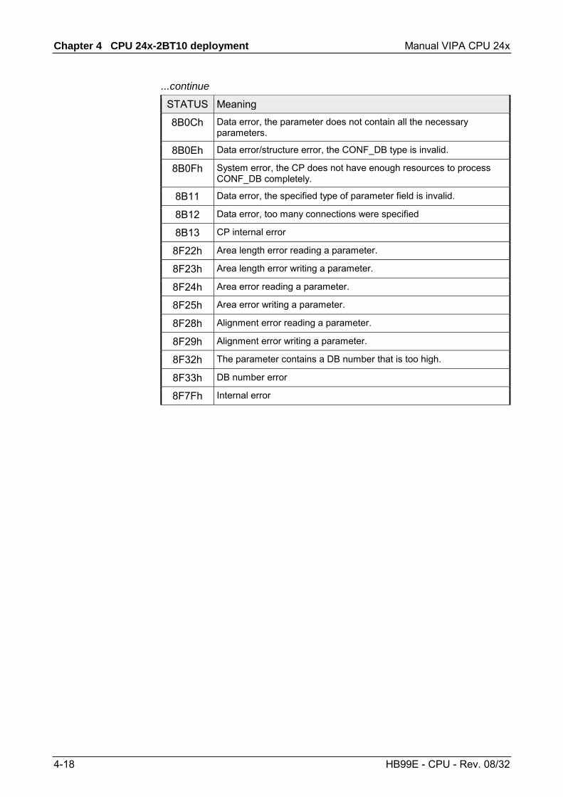
Chapter 4 CPU 24x-2BT10 deployment Manual VIPA CPU 24x
4-18 HB99E - CPU - Rev. 08/32
...continue
STATUS Meaning
8B0Ch Data error, the parameter does not contain all the necessary parameters.
8B0Eh Data error/structure error, the CONF_DB type is invalid.
8B0Fh System error, the CP does not have enough resources to process CONF_DB completely.
8B11 Data error, the specified type of parameter field is invalid.
8B12 Data error, too many connections were specified
8B13 CP internal error
8F22h Area length error reading a parameter.
8F23h Area length error writing a parameter.
8F24h Area error reading a parameter.
8F25h Area error writing a parameter.
8F28h Alignment error reading a parameter.
8F29h Alignment error writing a parameter.
8F32h The parameter contains a DB number that is too high.
8F33h DB number error
8F7Fh Internal error
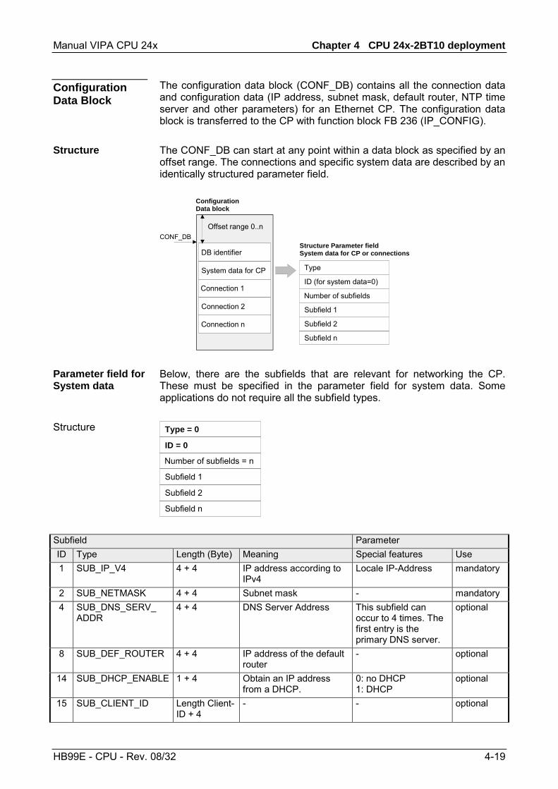
Manual VIPA CPU 24x Chapter 4 CPU 24x-2BT10 deployment
HB99E - CPU - Rev. 08/32 4-19
The configuration data block (CONF_DB) contains all the connection data and configuration data (IP address, subnet mask, default router, NTP time server and other parameters) for an Ethernet CP. The configuration data block is transferred to the CP with function block FB 236 (IP_CONFIG). The CONF_DB can start at any point within a data block as specified by an offset range. The connections and specific system data are described by an identically structured parameter field.
DB identifier
System data for CP
Connection 1
Connection 2
Connection n
Offset range 0..nCONF_DB
Structure Parameter fieldSystem data for CP or connections
ConfigurationData block
Type
ID (for system data=0)
Number of subfields
Subfield 1
Subfield 2
Subfield n
Below, there are the subfields that are relevant for networking the CP. These must be specified in the parameter field for system data. Some applications do not require all the subfield types.
Type = 0
ID = 0
Number of subfields = n
Subfield 1
Subfield 2
Subfield n
Subfield Parameter ID Type Length (Byte) Meaning Special features Use 1 SUB_IP_V4 4 + 4 IP address according to
IPv4 Locale IP-Address mandatory
2 SUB_NETMASK 4 + 4 Subnet mask - mandatory 4 SUB_DNS_SERV_
ADDR 4 + 4 DNS Server Address This subfield can
occur to 4 times. The first entry is the primary DNS server.
optional
8 SUB_DEF_ROUTER 4 + 4 IP address of the default router
- optional
14 SUB_DHCP_ENABLE 1 + 4 Obtain an IP address from a DHCP.
0: no DHCP 1: DHCP
optional
15 SUB_CLIENT_ID Length Client-ID + 4
- - optional
Configuration Data Block
Structure
Parameter field for System data
Structure
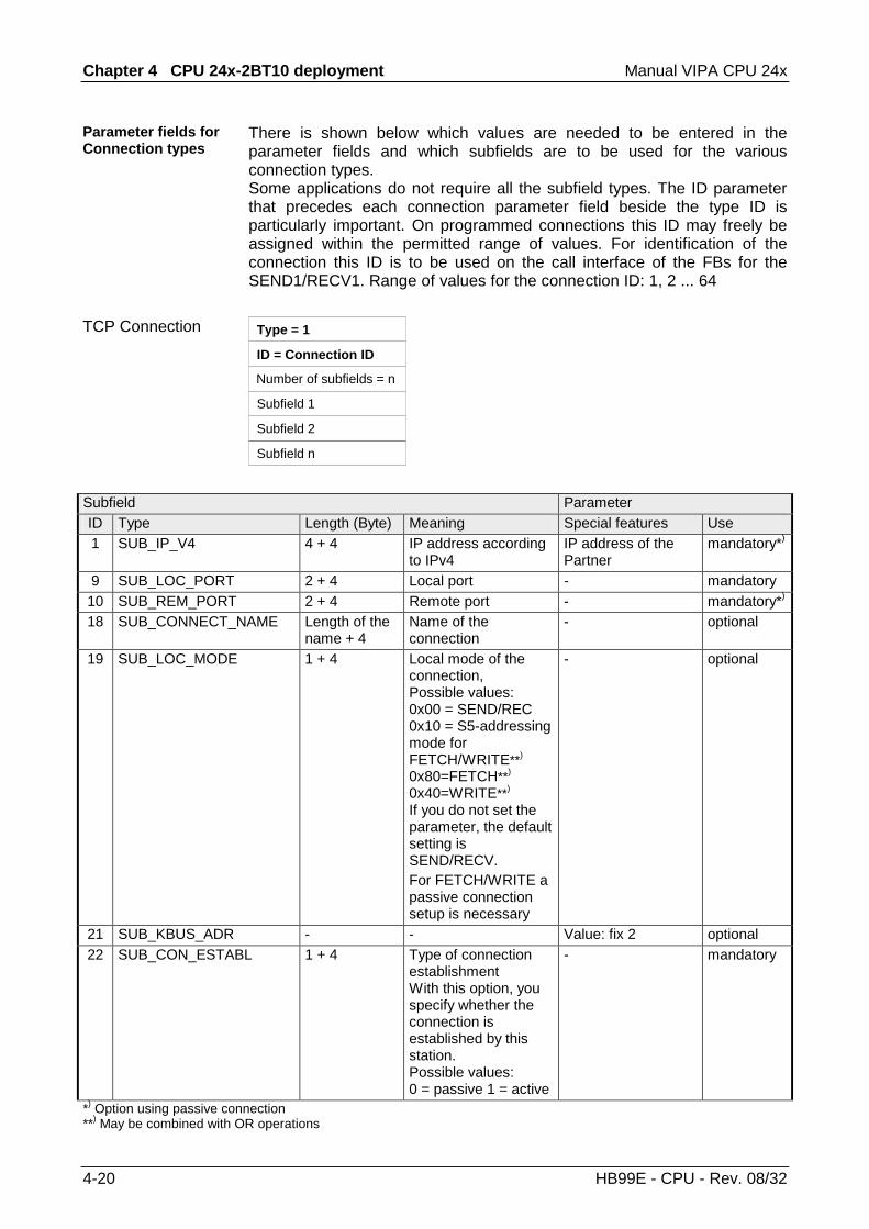
Chapter 4 CPU 24x-2BT10 deployment Manual VIPA CPU 24x
4-20 HB99E - CPU - Rev. 08/32
There is shown below which values are needed to be entered in the parameter fields and which subfields are to be used for the various connection types. Some applications do not require all the subfield types. The ID parameter that precedes each connection parameter field beside the type ID is particularly important. On programmed connections this ID may freely be assigned within the permitted range of values. For identification of the connection this ID is to be used on the call interface of the FBs for the SEND1/RECV1. Range of values for the connection ID: 1, 2 ... 64
Type = 1
ID = Connection ID
Number of subfields = n
Subfield 1
Subfield 2
Subfield n
Subfield Parameter ID Type Length (Byte) Meaning Special features Use 1 SUB_IP_V4 4 + 4 IP address according
to IPv4 IP address of the Partner
mandatory*)
9 SUB_LOC_PORT 2 + 4 Local port - mandatory 10 SUB_REM_PORT 2 + 4 Remote port - mandatory*)
18 SUB_CONNECT_NAME Length of the name + 4
Name of the connection
- optional
19 SUB_LOC_MODE 1 + 4 Local mode of the connection, Possible values: 0x00 = SEND/REC 0x10 = S5-addressing mode for FETCH/WRITE**) 0x80=FETCH**) 0x40=WRITE**) If you do not set the parameter, the default setting is SEND/RECV. For FETCH/WRITE a passive connection setup is necessary
- optional
21 SUB_KBUS_ADR - - Value: fix 2 optional 22 SUB_CON_ESTABL 1 + 4 Type of connection
establishment With this option, you specify whether the connection is established by this station. Possible values: 0 = passive 1 = active
- mandatory
*) Option using passive connection **) May be combined with OR operations
Parameter fields for Connection types
TCP Connection
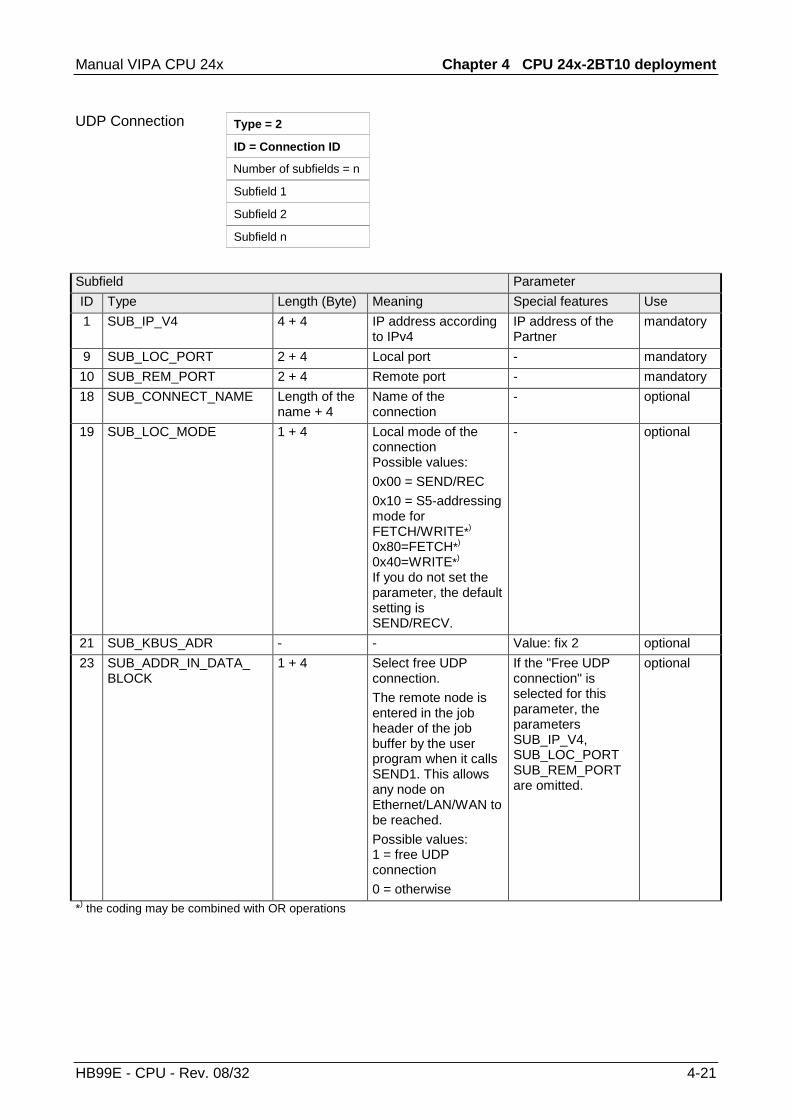
Manual VIPA CPU 24x Chapter 4 CPU 24x-2BT10 deployment
HB99E - CPU - Rev. 08/32 4-21
Type = 2
ID = Connection ID
Number of subfields = n
Subfield 1
Subfield 2
Subfield n
Subfield Parameter ID Type Length (Byte) Meaning Special features Use 1 SUB_IP_V4 4 + 4 IP address according
to IPv4 IP address of the Partner
mandatory
9 SUB_LOC_PORT 2 + 4 Local port - mandatory 10 SUB_REM_PORT 2 + 4 Remote port - mandatory 18 SUB_CONNECT_NAME Length of the
name + 4 Name of the connection
- optional
19 SUB_LOC_MODE 1 + 4 Local mode of the connection Possible values: 0x00 = SEND/REC 0x10 = S5-addressing mode for FETCH/WRITE*) 0x80=FETCH*) 0x40=WRITE*) If you do not set the parameter, the default setting is SEND/RECV.
- optional
21 SUB_KBUS_ADR - - Value: fix 2 optional 23 SUB_ADDR_IN_DATA_
BLOCK 1 + 4 Select free UDP
connection. The remote node is entered in the job header of the job buffer by the user program when it calls SEND1. This allows any node on Ethernet/LAN/WAN to be reached. Possible values: 1 = free UDP connection 0 = otherwise
If the "Free UDP connection" is selected for this parameter, the parameters SUB_IP_V4, SUB_LOC_PORT SUB_REM_PORT are omitted.
optional
*) the coding may be combined with OR operations
UDP Connection

Chapter 4 CPU 24x-2BT10 deployment Manual VIPA CPU 24x
4-22 HB99E - CPU - Rev. 08/32
Type = 3
ID = Connection ID
Number of subfields = n
Subfield 1
Subfield 2
Subfield n
Subfield Parameter ID Type Length (Byte) Meaning Special features Use 1 SUB_IP_V4 4 + 4 IP address according to
IPv4 IP address of the Partner
mandatory*)
11 SUB_LOC_PORT TSAP length + 4
Local TSAP - mandatory
12 SUB_REM_PORT TSAP length + 4
Remote TSAP - mandatory*)
18 SUB_CONNECT_NAME Length of the name + 4
Name of the connection - optional
19 SUB_LOC_MODE 1 + 4 Local mode of the connection Possible values: 0x00 = SEND/RECV 0x10 = S5-addressing mode for FETCH/WRITE**) 0x80=FETCH**) 0x40=WRITE**) If you do not set the parameter, the default setting is SEND/RECV.
- optional
21 SUB_KBUS_ADR - - Value: fix 2 optional 22 SUB_CON_ESTABL 1 + 4 Type of connection
establishment With this option, you specify whether the connection is estab-lished by this station. Possible values: 0 = passive; 1 = active
- mandatory
*) option using passive connection **) the coding may be combined with OR operation
ISO-on-TCP

Manual VIPA CPU 24x Chapter 4 CPU 24x-2BT10 deployment
HB99E - CPU - Rev. 08/32 4-23
SEND/RECEIVE with PLC program
For the execution of connection commands at the PLC, your CPU requires an user application. For this, exclusively the VIPA handling blocks FB 234 (SEND1) and FB 235 (RECV1) are used. By including these blocks into the cycle block OB 1 you may send and receive data cyclically.
For the communication between CPU and CP, the following FBs are available: FB 234 (SEND1) This block transfers the user data from the data area given in TYPE, DBNR, OFFS and LEN to the CP specified via ID. As data area you may set a PIQ, bit memory or data block area. When the data area has been transferred without errors, "order ready without error” is returned. FB 235 (RECV1) The block transfers the user data from the CP into a data area defined via TYPE, DBNR and OFFS. When the data area has been transferred without errors, "order ready without error” is returned. The CP processes send and receive commands independently from the CPU cycle and needs for this transfer time. The interface with the FB blocks to the user application is here synchronized by means of acknowledgements/receipts. For status evaluation the communication blocks return parameters that may be evaluated directly in the user application. These status displays are updated at every block call. Do not use cyclic calls of the communication blocks in OB 1. This causes a permanent communication between CPU and CP. Program instead the communication blocks within a time OB where the cycle time is higher than the time of the OB 1 respectively event controlled.
Overview
Communication blocks
Status displays
Deployment at high communication load
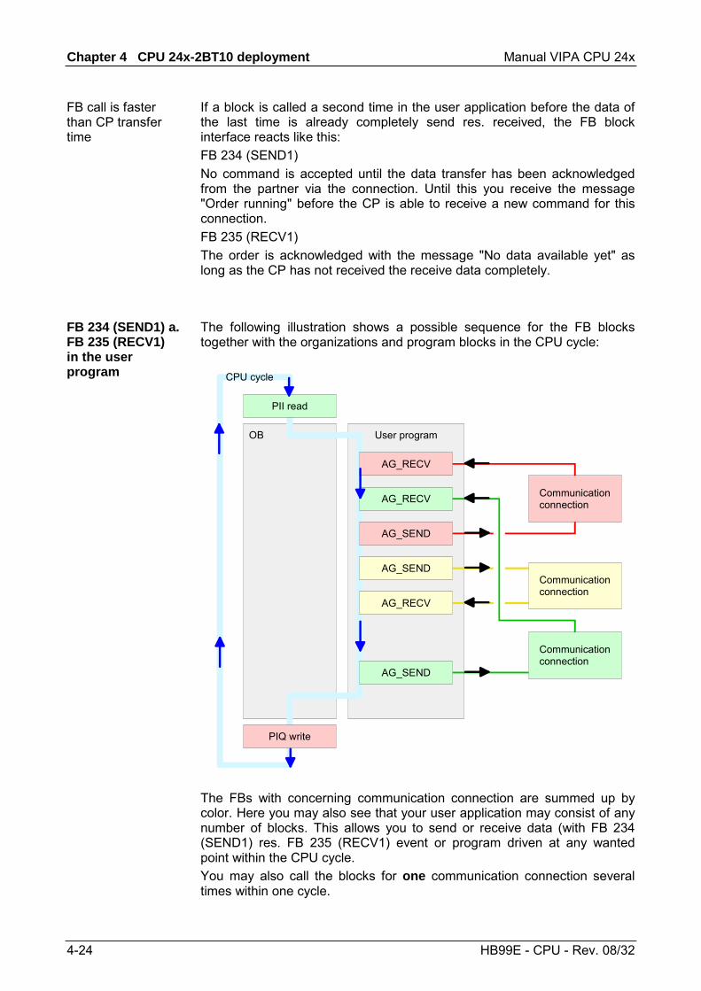
Chapter 4 CPU 24x-2BT10 deployment Manual VIPA CPU 24x
4-24 HB99E - CPU - Rev. 08/32
If a block is called a second time in the user application before the data of the last time is already completely send res. received, the FB block interface reacts like this: FB 234 (SEND1) No command is accepted until the data transfer has been acknowledged from the partner via the connection. Until this you receive the message "Order running" before the CP is able to receive a new command for this connection. FB 235 (RECV1) The order is acknowledged with the message "No data available yet" as long as the CP has not received the receive data completely.
The following illustration shows a possible sequence for the FB blocks together with the organizations and program blocks in the CPU cycle:
OB
Communicationconnection
Communicationconnection
Communicationconnection
PIQ write
PII read
User program
AG_SEND
AG_RECV
AG_RECV
AG_SEND
AG_SEND
AG_RECV
CPU cycle
The FBs with concerning communication connection are summed up by color. Here you may also see that your user application may consist of any number of blocks. This allows you to send or receive data (with FB 234 (SEND1) res. FB 235 (RECV1) event or program driven at any wanted point within the CPU cycle. You may also call the blocks for one communication connection several times within one cycle.
FB call is faster than CP transfer time
FB 234 (SEND1) a. FB 235 (RECV1) in the user program
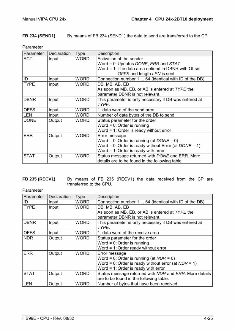
Manual VIPA CPU 24x Chapter 4 CPU 24x-2BT10 deployment
HB99E - CPU - Rev. 08/32 4-25
By means of FB 234 (SEND1) the data to send are transferred to the CP.
Parameter Declaration Type Description ACT Input WORD Activation of the sender
Word = 0: Updates DONE, ERR and STAT Word = 1: The data area defined in DBNR with Offset OFFS and length LEN is sent.
ID Input WORD Connection number 1 ... 64 (identical with ID of the DB) TYPE Input WORD DB, MB, AB, EB
As soon as MB, EB, or AB is entered at TYPE the parameter DBNR is not relevant.
DBNR Input WORD This parameter is only necessary if DB was entered at TYPE.
OFFS Input WORD 1. data word of the send area LEN Input WORD Number of data bytes of the DB to send DONE Output WORD Status parameter for the order
Word = 0: Order is running Word = 1: Order is ready without error
ERR Output WORD Error message Word = 0: Order is running (at DONE = 0) Word = 0: Order is ready without Error (at DONE = 1) Word = 1: Order is ready with error
STAT Output WORD Status message returned with DONE and ERR. More details are to be found in the following table
By means of FB 235 (RECV1) the data received from the CP are transferred to the CPU.
Parameter Declaration Type Description ID Input WORD Connection number 1 ... 64 (identical with ID of the DB) TYPE Input WORD DB, MB, AB, EB
As soon as MB, EB, or AB is entered at TYPE the parameter DBNR is not relevant.
DBNR Input WORD This parameter is only necessary if DB was entered at TYPE.
OFFS Input WORD 1. data word of the receive area NDR Output WORD Status parameter for the order
Word = 0: Order is running Word = 1: Order ready without error
ERR Output WORD Error message Word = 0: Order is running (at NDR = 0) Word = 0: Order is ready without error (at NDR = 1) Word = 1: Order is ready with error
STAT Output WORD Status message returned with NDR and ERR. More details are to be found in the following table.
LEN Output WORD Number of bytes that have been received.
FB 234 (SEND1)
Parameter
FB 235 (RECV1)
Parameter
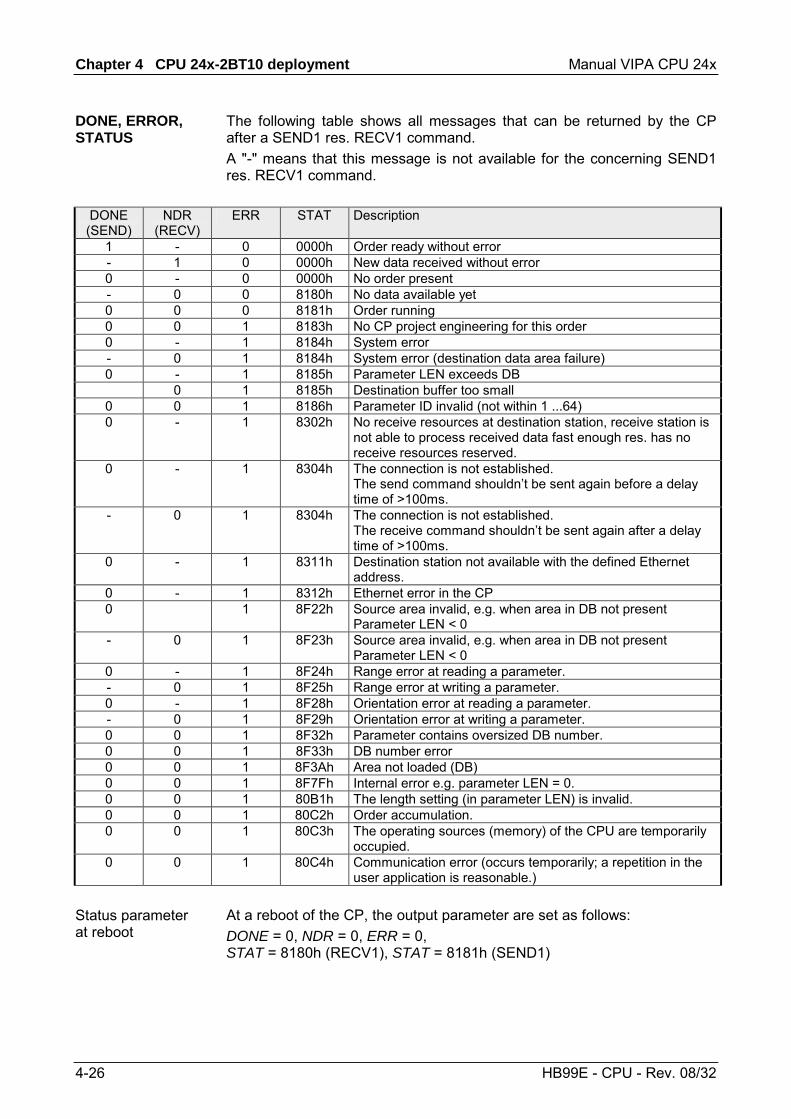
Chapter 4 CPU 24x-2BT10 deployment Manual VIPA CPU 24x
4-26 HB99E - CPU - Rev. 08/32
The following table shows all messages that can be returned by the CP after a SEND1 res. RECV1 command. A "-" means that this message is not available for the concerning SEND1 res. RECV1 command.
DONE (SEND)
NDR (RECV)
ERR STAT Description
1 - 0 0000h Order ready without error - 1 0 0000h New data received without error 0 - 0 0000h No order present - 0 0 8180h No data available yet 0 0 0 8181h Order running 0 0 1 8183h No CP project engineering for this order 0 - 1 8184h System error - 0 1 8184h System error (destination data area failure) 0 - 1 8185h Parameter LEN exceeds DB 0 1 8185h Destination buffer too small 0 0 1 8186h Parameter ID invalid (not within 1 ...64) 0 - 1 8302h No receive resources at destination station, receive station is
not able to process received data fast enough res. has no receive resources reserved.
0 - 1 8304h The connection is not established. The send command shouldn’t be sent again before a delay time of >100ms.
- 0 1 8304h The connection is not established. The receive command shouldn’t be sent again after a delay time of >100ms.
0 - 1 8311h Destination station not available with the defined Ethernet address.
0 - 1 8312h Ethernet error in the CP 0 1 8F22h Source area invalid, e.g. when area in DB not present
Parameter LEN < 0 - 0 1 8F23h Source area invalid, e.g. when area in DB not present
Parameter LEN < 0 0 - 1 8F24h Range error at reading a parameter. - 0 1 8F25h Range error at writing a parameter. 0 - 1 8F28h Orientation error at reading a parameter. - 0 1 8F29h Orientation error at writing a parameter. 0 0 1 8F32h Parameter contains oversized DB number. 0 0 1 8F33h DB number error 0 0 1 8F3Ah Area not loaded (DB) 0 0 1 8F7Fh Internal error e.g. parameter LEN = 0. 0 0 1 80B1h The length setting (in parameter LEN) is invalid. 0 0 1 80C2h Order accumulation. 0 0 1 80C3h The operating sources (memory) of the CPU are temporarily
occupied. 0 0 1 80C4h Communication error (occurs temporarily; a repetition in the
user application is reasonable.) At a reboot of the CP, the output parameter are set as follows: DONE = 0, NDR = 0, ERR = 0, STAT = 8180h (RECV1), STAT = 8181h (SEND1)
DONE, ERROR, STATUS
Status parameter at reboot

Manual VIPA CPU 24x Chapter 4 CPU 24x-2BT10 deployment
HB99E - CPU - Rev. 08/32 4-27
Coupling to other systems
The operating mode FETCH/WRITE supported at TCP res. ISO-on-TCP can be used for accesses of partner devices to the PLC system memory. To be able to use this access also for example for implementation in PC applications you have to know the telegram structure for orders. The specific headers for request and acknowledgement telegrams have per default a length of 16Byte and are described at the following pages.
The organization format is the abbreviated description of a data source or a data destination in a PLC environment. The available ORG formats are listed in the following table. The ERW-identifier is used for the addressing of data blocks. In this case the data block number is entered into this identifier. The start address and quantity provide the address for the memory area and they are stored in HIGH-/LOW- format (Motorola-formatted addresses)
Description Type Range ORG identifier BYTE 1...x ERW identifier BYTE 1...255 Start address HILOWORD 0...y Length HILOWORD 1...z
The following table contains a list of available ORG-formats. The "length" must not be entered as -1 (FFFFh).
ORG identifier 01h-04h CPU area DB MB EB AB ORG identifier 01h 02h 03h 04h Description Source/destination
data from/into data Block in main memory.
Source/destination data from/into flag memory area
Source/destination data from/into process image of the inputs (PII).
Source/destination data from/into process image of the outputs (PIO).
ERW identifier (DBNO)
DB, from where the source data is retrieved or to where the destination data is transferred.
irrelevant irrelevant irrelevant
Start address significance
DBB-No., from where the data is retrieved or where the data is saved.
MB-No., from where the data is retrieved or where the data is saved.
IB-No., from where the data is retrieved or where the data is saved.
QB-No., from where the data is retrieved or where the data is saved.
Length significance
Length of the source/destination data block in words
Length of the source/destination data block in bytes
Length of the source/destination data block in bytes
Length of the source/destination data block in bytes
Outline
ORG format
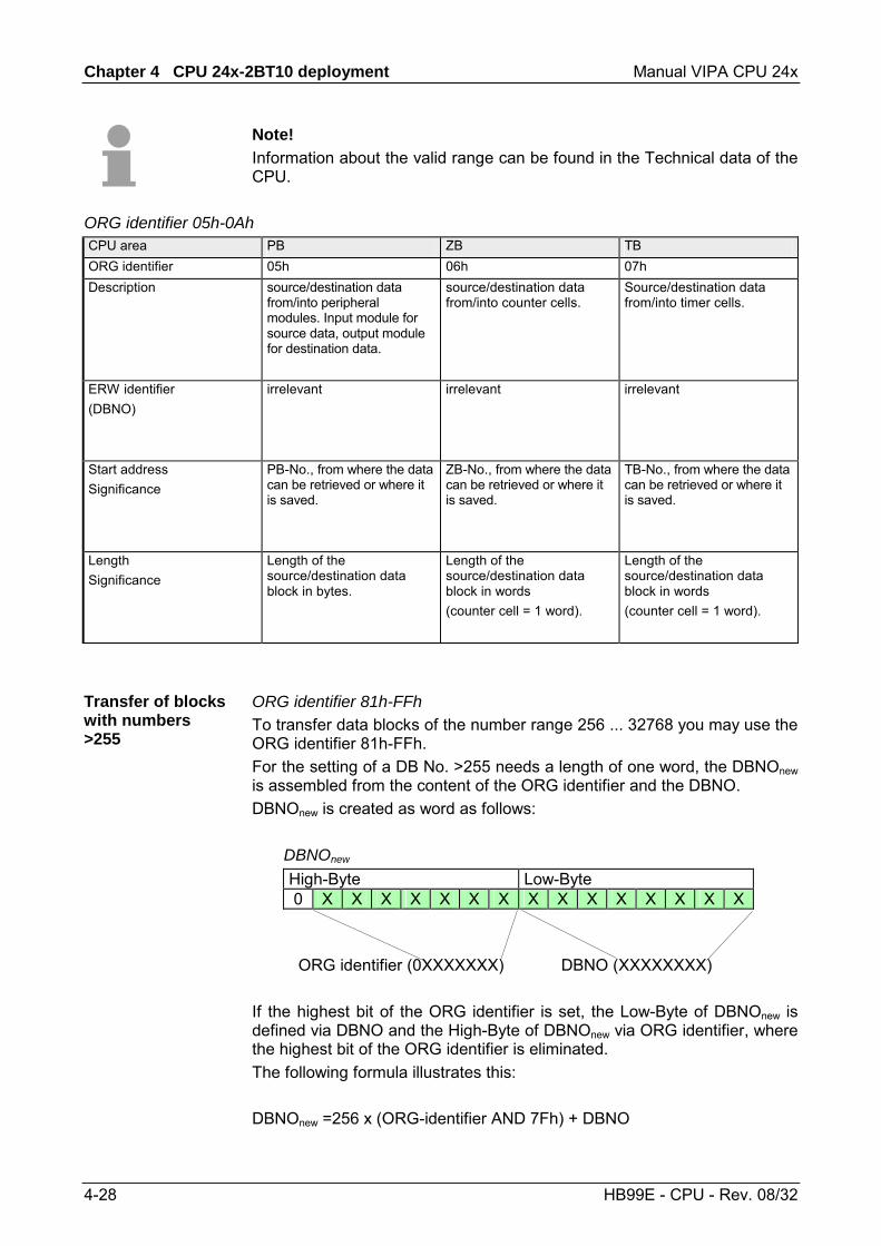
Chapter 4 CPU 24x-2BT10 deployment Manual VIPA CPU 24x
4-28 HB99E - CPU - Rev. 08/32
Note! Information about the valid range can be found in the Technical data of the CPU.
ORG identifier 05h-0Ah
CPU area PB ZB TB ORG identifier 05h 06h 07h Description source/destination data
from/into peripheral modules. Input module for source data, output module for destination data.
source/destination data from/into counter cells.
Source/destination data from/into timer cells.
ERW identifier (DBNO)
irrelevant irrelevant irrelevant
Start address Significance
PB-No., from where the data can be retrieved or where it is saved.
ZB-No., from where the data can be retrieved or where it is saved.
TB-No., from where the data can be retrieved or where it is saved.
Length Significance
Length of the source/destination data block in bytes.
Length of the source/destination data block in words (counter cell = 1 word).
Length of the source/destination data block in words (counter cell = 1 word).
ORG identifier 81h-FFh To transfer data blocks of the number range 256 ... 32768 you may use the ORG identifier 81h-FFh. For the setting of a DB No. >255 needs a length of one word, the DBNOnew is assembled from the content of the ORG identifier and the DBNO. DBNOnew is created as word as follows: DBNOnew
High-Byte Low-Byte 0 X X X X X X X X X X X X X X X
ORG identifier (0XXXXXXX)
DBNO (XXXXXXXX) If the highest bit of the ORG identifier is set, the Low-Byte of DBNOnew is defined via DBNO and the High-Byte of DBNOnew via ORG identifier, where the highest bit of the ORG identifier is eliminated. The following formula illustrates this: DBNOnew =256 x (ORG-identifier AND 7Fh) + DBNO
Transfer of blocks with numbers >255

Manual VIPA CPU 24x Chapter 4 CPU 24x-2BT10 deployment
HB99E - CPU - Rev. 08/32 4-29
For every READ and WRITE the CP generates PLC header for request and acknowledgment messages. Normally the length of these headers is 16Bytes and have the following structure:
Request telegram Remote Station
Acknowledgement telegram CP
System ID ="S5" (Word) System ID ="S5" (Word)Length Header =10h (Byte) Length Header =10h (Byte) ID OP-Code =01h (Byte) ID OP-Code =01h (Byte) Length OP-Code =03h (Byte) Length OP-Code =03h (Byte) OP-Code =03h (Byte) OP-Code =04h (Byte) ORG block =03h (Byte) Ackn. block =0Fh (Byte) Length ORG block =08h (Byte) Length Ack. block =03h (Byte) ORG identifier* (Byte) Error no. (Byte) ERW identifier (Byte) Empty block =FFh (Byte) Start address (Word) Length empty block =07h (Byte) Length (Word) 5 empty bytes attached Empty block =FFh (Byte) Length empty block =02h (Byte) Data up to 64kByte (only if error no.=0)
Request telegram Remote Station
Acknowledgement telegram CP
System ID ="S5" (Word) System ID ="S5" (Word)Length Header =10h (Byte) Length Header =10h (Byte) ID OP-Code =01h (Byte) ID OP-Code =01h (Byte) Length OP-Code =03h (Byte) Length OP-Code =03h (Byte) OP-Code =05h (Byte) OP-Code =06h (Byte) ORG block =03h (Byte) Ackn. block =0Fh (Byte) Length ORG block =08h (Byte) Length Ackn. block =03h (Byte) ORG identifier* (Byte) Error no. (Byte) ERW identifier (Byte) Empty block =FFh (Byte) Start address (Word) Length empty block =07h (Byte) Length (Word) 5 empty bytes attached Empty block =FFh (Byte) Length empty block =02h (Byte)
Data up to 64kByte (only if error no.=0)
*) More details to the data area is to be found at "ORG-Format" above.
The following messages can be returned via error no.: Error no. Message
00h No error occurred 01h The defined area cannot be read res. written
Structure of PLC-Header
WRITE
FETCH
Messages of error no.
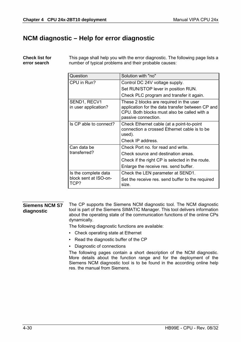
Chapter 4 CPU 24x-2BT10 deployment Manual VIPA CPU 24x
4-30 HB99E - CPU - Rev. 08/32
NCM diagnostic – Help for error diagnostic
This page shall help you with the error diagnostic. The following page lists a number of typical problems and their probable causes: Question Solution with "no" CPU in Run? Control DC 24V voltage supply.
Set RUN/STOP lever in position RUN. Check PLC program and transfer it again.
SEND1, RECV1 in user application?
These 2 blocks are required in the user application for the data transfer between CP and CPU. Both blocks must also be called with a passive connection.
Is CP able to connect? Check Ethernet cable (at a point-to-point connection a crossed Ethernet cable is to be used). Check IP address.
Can data be transferred?
Check Port no. for read and write. Check source and destination areas. Check if the right CP is selected in the route. Enlarge the receive res. send buffer.
Is the complete data block sent at ISO-on-TCP?
Check the LEN parameter at SEND1. Set the receive res. send buffer to the required size.
The CP supports the Siemens NCM diagnostic tool. The NCM diagnostic tool is part of the Siemens SIMATIC Manager. This tool delivers information about the operating state of the communication functions of the online CPs dynamically. The following diagnostic functions are available: • Check operating state at Ethernet • Read the diagnostic buffer of the CP • Diagnostic of connections The following pages contain a short description of the NCM diagnostic. More details about the function range and for the deployment of the Siemens NCM diagnostic tool is to be found in the according online help res. the manual from Siemens.
Check list for error search
Siemens NCM S7 diagnostic

Manual VIPA CPU 24x Chapter 4 CPU 24x-2BT10 deployment
HB99E - CPU - Rev. 08/32 4-31
There are two options to start the diagnostic tool: • Via Windows-START menu > SIMATIC ... NCM S7 > Diagnostic • Within the project engineering res. the hardware configuration via the
register "Diagnostic" in the "Property" dialog with [Execute]. The working surface of the diagnostic tool has the following structure: The navigation area at the left side contains the hierarchical listed diagnostic objects. Depending on CP type and configured connections there is an adjusted object structure in the navigation area. The information area at the right side always shows the result of the navigation function you chose in the navigation area.
Navigation area Information area
4
A diagnostic always requires an online connection to the CP you want to
control. For this click on at the symbol bar. The following dialog window appears:
Set the following parameters at destination station: Connection...: Ind. Ethernet TCP/IP Station addr.: Enter the IP address of the CP Module rack/slot: Always choose rack 0 and slot 4 when using System 200V. Set your PG/PC interface to TCP/IP...RFC1006. [OK] starts the online diagnostic.
Start NCM diagnostic
Structure
No diagnostic without connection

Chapter 4 CPU 24x-2BT10 deployment Manual VIPA CPU 24x
4-32 HB99E - CPU - Rev. 08/32
The CP has a diagnostic buffer. This has the architecture of a ring memory and may store up to 100 diagnostic messages. The NCM diagnostic allows you to monitor and evaluate the CP diagnostic messages via the diagnostic object Diagnostic buffer. Via a double click on a diagnostic message the NCM diagnostic shows further information.
You execute a diagnostic by clicking on a diagnostic object in the navigation area. More functions are available via the menu and the symbol bar.
Note! Please always control the preconditions for an operative communication using the check at the beginning of this chapter.
For the aimed diagnostic deployment the following approach is convenient: • Start diagnostic.
• Open the dialog for the online connection with , enter connection parameters and establish the online connection with [OK].
• Identify the CP and check the recent state of the CP via module status. • Check the connections for particularities like:
- Connection status - Receive status - Send status
• Control and evaluate the diagnostic buffer of the CP via diagnostic buffer.
• As needed, alter project engineering res. programming and restart diagnostic.
Read diagnostic buffer
Approach for diagnostic
Manual VIPA CPU 24x Chapter 5 CPU 24x-2BT01 deployment
HB99E - CPU - Rev. 08/32 5-1
Chapter 5 CPU 24x-2BT01 deployment
The following chapter describes the deployment of the Net-CPU 24x2BT01 and the H1 and/or TCP/IP communication procedure. It also contains an introduction to the configuration of the module by means of WinNCS along with a real-world example.
Topic Page Chapter 5 CPU 24x-2BT01 deployment........................................... 5-1
Principles.............................................................................................. 5-2 Network planning.................................................................................. 5-7 Standards and norms ........................................................................... 5-9 Ethernet and IP-addresses................................................................. 5-10 Configuration of the CPU 24x NET..................................................... 5-12 Examples for the configuration ........................................................... 5-16 Boot behavior ..................................................................................... 5-29 System properties of the CPU 24x NET ............................................. 5-30 Communication links to foreign systems............................................. 5-32 Status and error indicators ................................................................. 5-36 Test program for TCP/IP connections................................................. 5-44
Outline
Contents
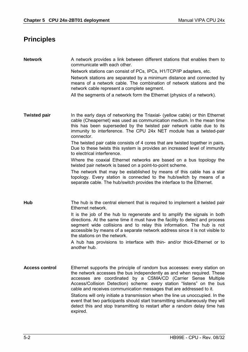
Chapter 5 CPU 24x-2BT01 deployment Manual VIPA CPU 24x
5-2 HB99E - CPU - Rev. 08/32
Principles
A network provides a link between different stations that enables them to communicate with each other. Network stations can consist of PCs, IPCs, H1/TCP/IP adapters, etc. Network stations are separated by a minimum distance and connected by means of a network cable. The combination of network stations and the network cable represent a complete segment. All the segments of a network form the Ethernet (physics of a network).
In the early days of networking the Triaxial- (yellow cable) or thin Ethernet cable (Cheapernet) was used as communication medium. In the mean time this has been superseded by the twisted pair network cable due to its immunity to interference. The CPU 24x NET module has a twisted-pair connector. The twisted pair cable consists of 4 cores that are twisted together in pairs. Due to these twists this system is provides an increased level of immunity to electrical interference. Where the coaxial Ethernet networks are based on a bus topology the twisted pair network is based on a point-to-point scheme. The network that may be established by means of this cable has a star topology. Every station is connected to the hub/switch by means of a separate cable. The hub/switch provides the interface to the Ethernet.
The hub is the central element that is required to implement a twisted pair Ethernet network. It is the job of the hub to regenerate and to amplify the signals in both directions. At the same time it must have the facility to detect and process segment wide collisions and to relay this information. The hub is not accessible by means of a separate network address since it is not visible to the stations on the network. A hub has provisions to interface with thin- and/or thick-Ethernet or to another hub.
Ethernet supports the principle of random bus accesses: every station on the network accesses the bus independently as and when required. These accesses are coordinated by a CSMA/CD (Carrier Sense Multiple Access/Collision Detection) scheme: every station “listens” on the bus cable and receives communication messages that are addressed to it. Stations will only initiate a transmission when the line us unoccupied. In the event that two participants should start transmitting simultaneously they will detect this and stop transmitting to restart after a random delay time has expired.
Network
Twisted pair
Hub
Access control
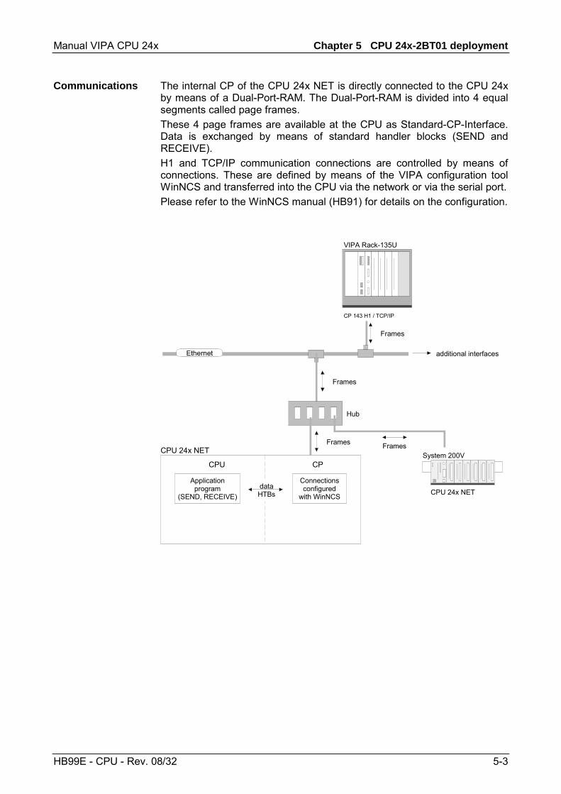
Manual VIPA CPU 24x Chapter 5 CPU 24x-2BT01 deployment
HB99E - CPU - Rev. 08/32 5-3
The internal CP of the CPU 24x NET is directly connected to the CPU 24x by means of a Dual-Port-RAM. The Dual-Port-RAM is divided into 4 equal segments called page frames. These 4 page frames are available at the CPU as Standard-CP-Interface. Data is exchanged by means of standard handler blocks (SEND and RECEIVE). H1 and TCP/IP communication connections are controlled by means of connections. These are defined by means of the VIPA configuration tool WinNCS and transferred into the CPU via the network or via the serial port. Please refer to the WinNCS manual (HB91) for details on the configuration.
CPU 24x NET
CPCPU
Connectionsconfigured
with WinNCS
Ethernet additional interfaces
dataHTBs
Applicationprogram
(SEND, RECEIVE)
Frames
Hub
Frames
VIPA Rack-135U
CP 143 H1 / TCP/IP
System 200V
CPU 24x NET
Frames
Frames
Communications

Chapter 5 CPU 24x-2BT01 deployment Manual VIPA CPU 24x
5-4 HB99E - CPU - Rev. 08/32
H1, which is also referred to as "Industrial Ethernet", is a protocol that is based upon the Ethernet-Standard. H1 information is exchange between stations by means of H1-frames that are transferred on transport-connections. A transport-connection is a logical link between two access points to the transport-services on different stations. A transportation-connection is based on addressing information that provides an exact description of the path between the two access-points. The following parameters describe a transport-connection: • MAC-Address, also referred to as Ethernet address, defines the access
facility of a station. • TSAP Transport-Service-Access-Points identifies access channels for
the services of the transport protocol. The CP prepares a data buffer and transfers the data into the data buffer by means of the background communication function SEND-ALL. Then the CP creates an H1-Frame and transfers this Frame to the partner station when this has enabled reception. When the partner station has received the H1-Frames the CP receives an acknowledgment. Next it transfers the status of the SEND-job into the respective indicator word by means of the background communication function RECEIVE-ALL. This ensures error-free communications. The following illustration shows the principle:
SEND HTB
Data
SEND-ALL
Status word
Data
RECEIVE-ALL
H1-Frame
SEND job
Receive enabled
H1-Frame
CPU CP
Receive ackn.every frameReception terminated
H1-Bus
Data
Status word
RECEIVE-ALL
Receive job
CPUCP
Reception terminated
H1-Frame
Data
RECEIVE HTB
RECEIVE-ALL
Note! Due to the large quantity of acknowledgment telegrams that are transferred via an H1-transport-connection the load on the network is appreciably higher under H1 than under TCP/IP, however, under TCP/IP the security of the data is reduced!
H1 - Industrial Ethernet
Manual VIPA CPU 24x Chapter 5 CPU 24x-2BT01 deployment
HB99E - CPU - Rev. 08/32 5-5
TCP/IP protocols are available on all major systems. At the bottom end this applies to simple PCs, through to the typical mini-computer up to mainframes (TCP/IP implementations also exist for IBM-systems) and special processors like vector processors and parallel computers. For this reason TCP/IP is often used to assemble heterogeneous system pools. TCP/IP can be employed to establish extensive open network solutions between the different business units of an enterprise. For example, TCP/IP can be used for the following applications: • centralized control and supervision of production plants, • transfer of the state of production machines, • management information, • production statistics, • the transfer of large quantities of data. TCP and IP only provide support for two of the protocols required for a complete architecture. Programs like " FTP " and " Telnet " are available for the application layer of the PC. The application layer of the CPU 24x NET - CP is defined by the application program using the standard handler blocks. These application programs exchange data by means of the TCP or UDP protocols of the transportation layer. These communicate with the IP-protocol of the Internet layer. IP The main purpose of IP is to provide the addressing to data packets. This means that IP has the same function as an envelope has for a letter. The address is used by the network to determine the destination and to route the data-packets accordingly. The protocol divides the data into small portions since different networks use different size data packets. A number is assigned to each packet. This is used to acknowledge reception and to reassemble the original data. To transfer these sequence numbers via the network TCP and IP is provided with a unique envelope where these numbers are recorded. TCP A packet of data is inserted into a TCP-envelope. This is then inserted into an IP-envelope and transferred to the network. TCP provides for the secure transfer of data via network. TCP detects and corrects communication errors. In this way TCP-connections are relatively safe. UDP provides a much faster communication link. However, it does not cater for missing data packets, nor does it check the sequence of the packets. UDP is an unsecured protocol.
TCP/IP

Chapter 5 CPU 24x-2BT01 deployment Manual VIPA CPU 24x
5-6 HB99E - CPU - Rev. 08/32
OPEN / CONNECT Opens a virtual connection to communication partner when the station is in active mode and waits for a connection from a communication partner in passive mode. SEND Transfers a data buffer to TCP for transmission to a communication partner. RECEIVE Receives data from a communication partner. CLOSE Terminates a virtual connection.
TCP/IP or H1 application
TCP/IP/H1
System 200V
CPU 24x NET
System 200V
CPU 24x NET
CP 143 H1 / TCP/IP
Visualization and shop floor data collection via DDE-server
VIPA Rack-135U
HubVIPA Rack-135U
CP 143 H1 / TCP/IP
TCP/IP services
Example of an H1 or TCP/IP application
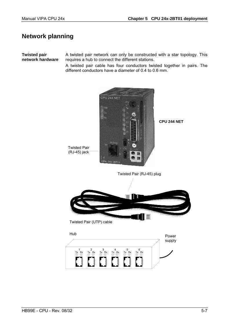
Manual VIPA CPU 24x Chapter 5 CPU 24x-2BT01 deployment
HB99E - CPU - Rev. 08/32 5-7
Network planning
A twisted pair network can only be constructed with a star topology. This requires a hub to connect the different stations. A twisted pair cable has four conductors twisted together in pairs. The different conductors have a diameter of 0.4 to 0.6 mm.
Twisted Pair (RJ-45) plug
Twisted Pair(RJ-45) jack
Twisted Pair (UTP) cable
1 2 3 4 5 6Tx Rx Tx Rx Tx Rx Tx Rx Tx Rx Tx Rx
Powersupply
Hub
CPU 244 NET
Twisted pair network hardware
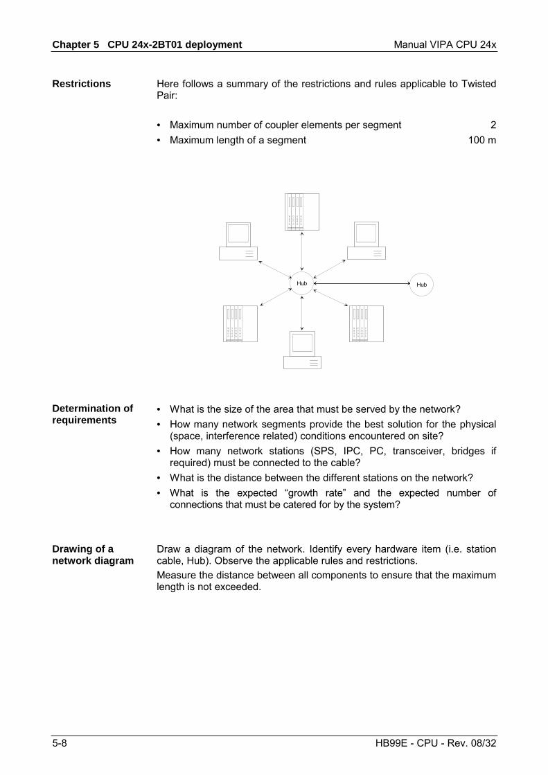
Chapter 5 CPU 24x-2BT01 deployment Manual VIPA CPU 24x
5-8 HB99E - CPU - Rev. 08/32
Here follows a summary of the restrictions and rules applicable to Twisted Pair: • Maximum number of coupler elements per segment 2 • Maximum length of a segment 100 m
• What is the size of the area that must be served by the network? • How many network segments provide the best solution for the physical
(space, interference related) conditions encountered on site? • How many network stations (SPS, IPC, PC, transceiver, bridges if
required) must be connected to the cable? • What is the distance between the different stations on the network? • What is the expected “growth rate” and the expected number of
connections that must be catered for by the system?
Draw a diagram of the network. Identify every hardware item (i.e. station cable, Hub). Observe the applicable rules and restrictions. Measure the distance between all components to ensure that the maximum length is not exceeded.
Restrictions
Determination of requirements
Drawing of a network diagram
Manual VIPA CPU 24x Chapter 5 CPU 24x-2BT01 deployment
HB99E - CPU - Rev. 08/32 5-9
Standards and norms
That main property of the bus structure is that it consists of a single physical connection. The physical communication medium consists of: • one or more electrical cables (twisted pair cable), • coaxial cable (Triaxial cable), • fiber optic cables. The applicable rules and regulations must be satisfied in order to establish reliable communications between the different stations. These agreements define the form of the data protocol, the method of access to the bus and other principles that are important for reliable communications. The VIPA CPU 24x NET was developed in accordance with the standards defined by ISO.
International and national committees have defined the following standards and guidelines for networking technologies:
ANSI American National Standards Institute The ANSI X3T9.5 standard currently defines the provisions for high speed LAN’s (100 MB/s) based on fiber optic technology. (FDDI) Fiber Distributed Data Interface.
CCITT Committee Consultative Internationale de Telephone et Telegraph. Amongst others, this advisory committee has produced the provisions for the connection of industrial networks (MAP) to office networks (TOP) on Wide Area Networks (WAN).
ECMA European Computer Manufacturers Association. Has produced various MAP and TOP standards.
EIA Electrical Industries Association (USA) This committee has issued standard definitions like RS232 (V.24) and RS511.
IEC International Electrotechnical Commission. Defines certain special standards, e.g. for the Field Bus.
ISO International Organization for Standardization. This association of national standards organizations developed the OSI-model (ISO/TC97/SC16). It provides the framework for the standardization of data communications. ISO standards are included in different national standards like for example UL and DIN.
IEEE Institute of Electrical and Electronic Engineers (USA). The project-group 802 determines LAN-standards for transfer rates of 1 to 20 MB/s. IEEE standards often form the basis for ISO-standards, e.g. IEEE 802.3 = ISO 8802.3.
Standards and guidelines
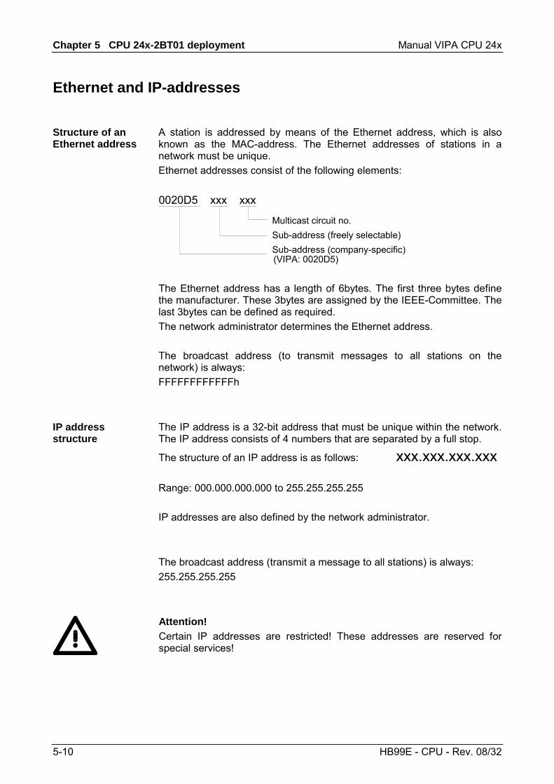
Chapter 5 CPU 24x-2BT01 deployment Manual VIPA CPU 24x
5-10 HB99E - CPU - Rev. 08/32
Ethernet and IP-addresses
A station is addressed by means of the Ethernet address, which is also known as the MAC-address. The Ethernet addresses of stations in a network must be unique. Ethernet addresses consist of the following elements: 0020D5 xxx xxx
Multicast circuit no.Sub-address (freely selectable)Sub-address (company-specific)(VIPA: 0020D5)
The Ethernet address has a length of 6bytes. The first three bytes define the manufacturer. These 3bytes are assigned by the IEEE-Committee. The last 3bytes can be defined as required. The network administrator determines the Ethernet address. The broadcast address (to transmit messages to all stations on the network) is always: FFFFFFFFFFFFh
The IP address is a 32-bit address that must be unique within the network. The IP address consists of 4 numbers that are separated by a full stop.
The structure of an IP address is as follows: xxx.xxx.xxx.xxx Range: 000.000.000.000 to 255.255.255.255 IP addresses are also defined by the network administrator.
The broadcast address (transmit a message to all stations) is always: 255.255.255.255
Attention! Certain IP addresses are restricted! These addresses are reserved for special services!
Structure of an Ethernet address
IP address structure
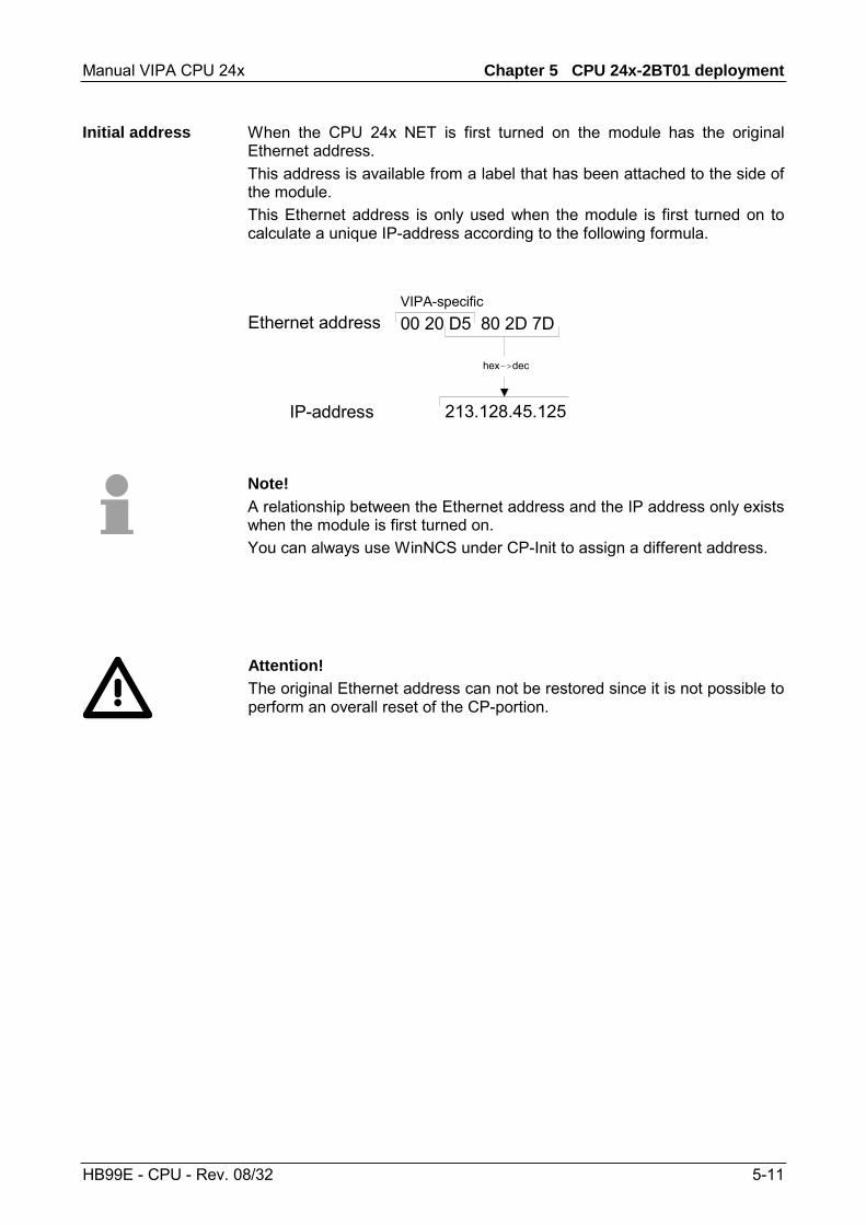
Manual VIPA CPU 24x Chapter 5 CPU 24x-2BT01 deployment
HB99E - CPU - Rev. 08/32 5-11
When the CPU 24x NET is first turned on the module has the original Ethernet address. This address is available from a label that has been attached to the side of the module. This Ethernet address is only used when the module is first turned on to calculate a unique IP-address according to the following formula.
00 20 D5 80 2D 7DEthernet address
hex->dec
213.128.45.125IP-address
VIPA-specific
Note! A relationship between the Ethernet address and the IP address only exists when the module is first turned on. You can always use WinNCS under CP-Init to assign a different address.
Attention! The original Ethernet address can not be restored since it is not possible to perform an overall reset of the CP-portion.
Initial address
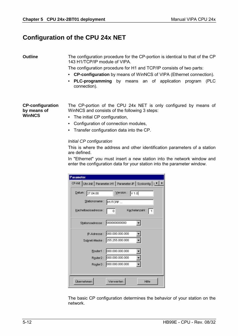
Chapter 5 CPU 24x-2BT01 deployment Manual VIPA CPU 24x
5-12 HB99E - CPU - Rev. 08/32
Configuration of the CPU 24x NET
The configuration procedure for the CP-portion is identical to that of the CP 143 H1/TCP/IP module of VIPA. The configuration procedure for H1 and TCP/IP consists of two parts: • CP-configuration by means of WinNCS of VIPA (Ethernet connection). • PLC-programming by means an of application program (PLC
connection).
The CP-portion of the CPU 24x NET is only configured by means of WinNCS and consists of the following 3 steps: • The initial CP configuration, • Configuration of connection modules, • Transfer configuration data into the CP.
Initial CP configuration This is where the address and other identification parameters of a station are defined. In "Ethernet" you must insert a new station into the network window and enter the configuration data for your station into the parameter window.
The basic CP configuration determines the behavior of your station on the network.
Outline
CP-configuration by means of WinNCS
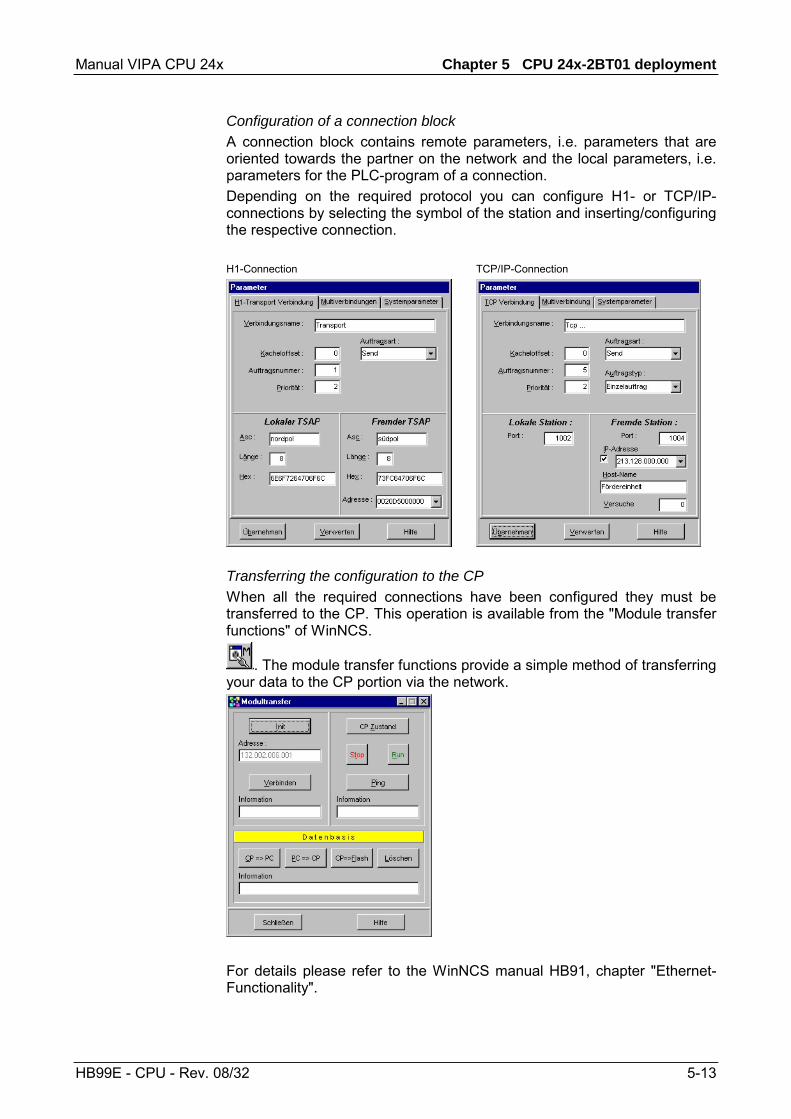
Manual VIPA CPU 24x Chapter 5 CPU 24x-2BT01 deployment
HB99E - CPU - Rev. 08/32 5-13
Configuration of a connection block A connection block contains remote parameters, i.e. parameters that are oriented towards the partner on the network and the local parameters, i.e. parameters for the PLC-program of a connection. Depending on the required protocol you can configure H1- or TCP/IP-connections by selecting the symbol of the station and inserting/configuring the respective connection. H1-Connection
TCP/IP-Connection
Transferring the configuration to the CP When all the required connections have been configured they must be transferred to the CP. This operation is available from the "Module transfer functions" of WinNCS.
. The module transfer functions provide a simple method of transferring your data to the CP portion via the network.
For details please refer to the WinNCS manual HB91, chapter "Ethernet-Functionality".
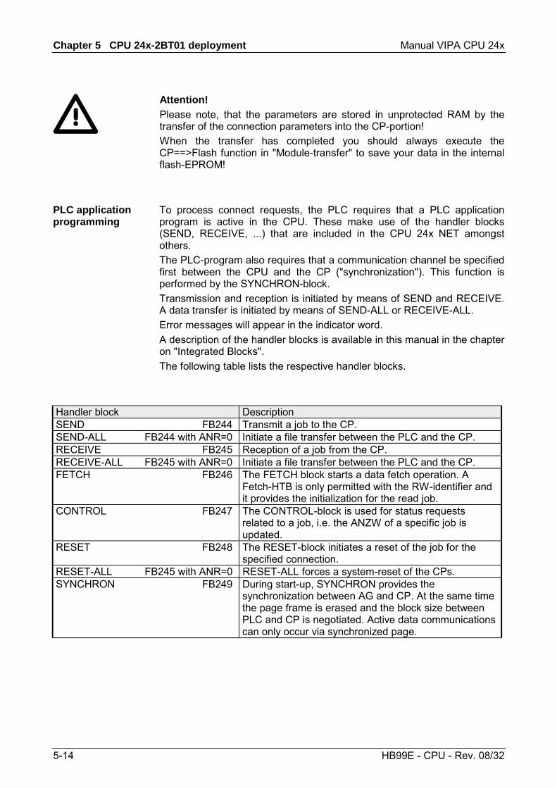
Chapter 5 CPU 24x-2BT01 deployment Manual VIPA CPU 24x
5-14 HB99E - CPU - Rev. 08/32
Attention! Please note, that the parameters are stored in unprotected RAM by the transfer of the connection parameters into the CP-portion! When the transfer has completed you should always execute the CP==>Flash function in "Module-transfer" to save your data in the internal flash-EPROM!
To process connect requests, the PLC requires that a PLC application program is active in the CPU. These make use of the handler blocks (SEND, RECEIVE, ...) that are included in the CPU 24x NET amongst others. The PLC-program also requires that a communication channel be specified first between the CPU and the CP ("synchronization"). This function is performed by the SYNCHRON-block. Transmission and reception is initiated by means of SEND and RECEIVE. A data transfer is initiated by means of SEND-ALL or RECEIVE-ALL. Error messages will appear in the indicator word. A description of the handler blocks is available in this manual in the chapter on "Integrated Blocks". The following table lists the respective handler blocks.
Handler block Description SEND FB244 Transmit a job to the CP. SEND-ALL FB244 with ANR=0 Initiate a file transfer between the PLC and the CP. RECEIVE FB245 Reception of a job from the CP. RECEIVE-ALL FB245 with ANR=0 Initiate a file transfer between the PLC and the CP. FETCH FB246 The FETCH block starts a data fetch operation. A
Fetch-HTB is only permitted with the RW-identifier and it provides the initialization for the read job.
CONTROL FB247 The CONTROL-block is used for status requests related to a job, i.e. the ANZW of a specific job is updated.
RESET FB248 The RESET-block initiates a reset of the job for the specified connection.
RESET-ALL FB245 with ANR=0 RESET-ALL forces a system-reset of the CPs. SYNCHRON FB249 During start-up, SYNCHRON provides the
synchronization between AG and CP. At the same time the page frame is erased and the block size between PLC and CP is negotiated. Active data communications can only occur via synchronized page.
PLC application programming
Manual VIPA CPU 24x Chapter 5 CPU 24x-2BT01 deployment
HB99E - CPU - Rev. 08/32 5-15
Synchronization When a PLC starts up every one of the configured interfaces of the CPs must be synchronized by means of SYNCHRON. This condition applies to every start-up method of the respective PLC: • OB21 for manual restart, • OB22 for a restart after a power failure.
OB22 or OB21 00000 : 00002 :SPA FB 22 Delay time and synchron NAME #ANLAUF 00009 :BE
FB22 BSTNAME #NETZEIN 00022 :SPA FB 249 Synchron block NAME #SYNCHRON SSNR =KY 0,0 SSNR or page frame base 0 BLGR =KY 0,6 Block size 6 (512 Byte) PAFE =MB 199 Config. error byte MB199 0002C : 0003E :BE After power is turned on the CPU24x NET requires app. 15s for the boot-procedure. If the PLC should issue a request a synchronization during this time an error is returned in the configuration error byte PAFE. This message is removed when the CP module has completed the boot process. The timer in this block is initially set to 20s. Processing will be stopped if the synchronization is not completed properly within this period. The following table shows the available block sizes.
Block size CP block size in byte 0 Use the preset block size 1 16 2 32 3 64 4 128 5 256 6 512
255 512 Cycle Send and receive blocks SEND and RECEIVE, which initiate the sending and receiving operations, must be configured in the cycle program OB1. The actual data-transfer is performed by the blocks SEND ALL and RECEIVE ALL. Purely passive connections only require the components SEND ALL or RECEIVE ALL. To protect the data-transfer you should integrate various checkpoints that evaluate the indicator word.
Chapter 5 CPU 24x-2BT01 deployment Manual VIPA CPU 24x
5-16 HB99E - CPU - Rev. 08/32
Examples for the configuration
This chapter provides an introduction to use of the H1 and TCP/IP bus system for the System 200V. This introduction is centered on the VIPA configuration software WinNCS. The object of this chapter is to create a small communication system between a CPU 24x NET and a CP 143 H1 / TCP/IP that provides a simple approach to the control of the communication processes. Knowledge of the CP handler blocks is required. CP handler blocks are standard function blocks. These provide the options required to utilize the communication functions in the programs of the programmable logic controllers. The minimum technical equipment required for the examples is as follows: 1 CPU 24x NET from VIPA, 1 Rack-135U from VIPA, 1 CPU 928 B/C from VIPA, 1 CP 143 H1 / TCP/IP module from VIPA. Communication line consisting of: - 2 Bus cables, - 1 HUB. Software package - Configuration software WinNCS from VIPA - MC5 programming package for PLC programming from VIPA The following example explains the requirements of the problem in detail. The implementation of the example requires that the two programmable logic controllers be programmed in the Siemens STEP 5 language as well as the configuration of the communication processors in WinNCS.
Outline and requirements
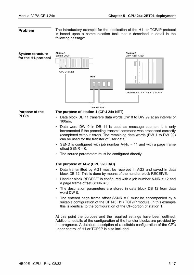
Manual VIPA CPU 24x Chapter 5 CPU 24x-2BT01 deployment
HB99E - CPU - Rev. 08/32 5-17
The introductory example for the application of the H1- or TCP/IP protocol is based upon a communication task that is described in detail in the following passage:
CPU 928 B/C, CP 143 H1 / TCP/IP
Station 2VIPA Rack-135U
Station 1System 200V
CPU 24x NET
Twisted Pair
Hub
The purpose of station 1 (CPU 24x NET) • Data block DB 11 transfers data words DW 0 to DW 99 at an interval of
100ms. • Data word DW 0 in DB 11 is used as message counter. It is only
incremented if the preceding transmit command was processed correctly (completed without error). The remaining data words (DW 1 to DW 99) can be used for the transfer of user data.
• SEND is configured with job number A-Nr. = 11 and with a page frame offset SSNR = 0.
• The source parameters must be configured directly. The purpose of AG2 (CPU 928 B/C) • Data transmitted by AG1 must be received in AG2 and saved in data
block DB 12. This is done by means of the handler block RECEIVE. • Handler block RECEIVE is configured with a job number A-NR = 12 and
a page frame offset SSNR = 0. • The destination parameters are stored in data block DB 12 from data
word DW 0. • The entered page frame offset SSNR = 0 must be accompanied by a
suitable configuration of the CP143 H1 / TCP/IP module. In this example this is identical to the configuration of the CP-portion of station 1.
At this point the purpose and the required settings have been outlined. Additional details of the configuration of the handler blocks are provided by the programs. A detailed description of a suitable configuration of the CP's under control of H1 or TCP/IP is also included.
Problem
System structure for the H1-protocol
Purpose of the PLC’s
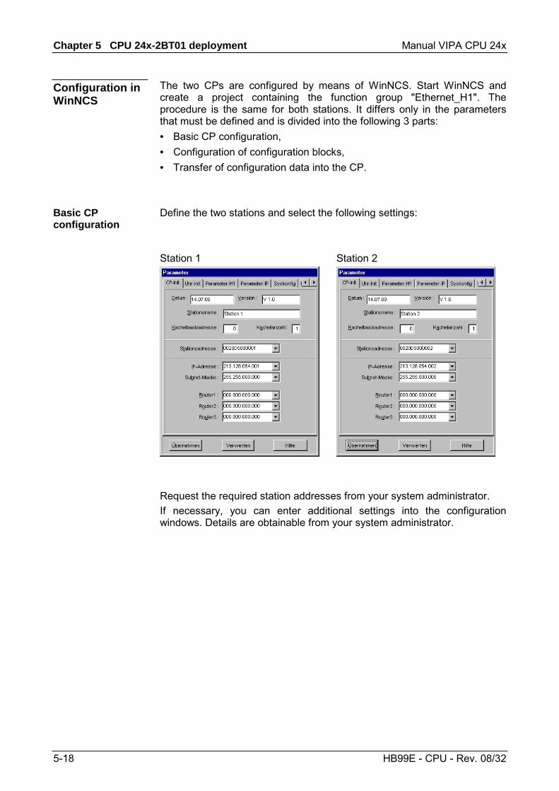
Chapter 5 CPU 24x-2BT01 deployment Manual VIPA CPU 24x
5-18 HB99E - CPU - Rev. 08/32
The two CPs are configured by means of WinNCS. Start WinNCS and create a project containing the function group "Ethernet_H1". The procedure is the same for both stations. It differs only in the parameters that must be defined and is divided into the following 3 parts: • Basic CP configuration, • Configuration of configuration blocks, • Transfer of configuration data into the CP.
Define the two stations and select the following settings:
Station 1 Station 2
Request the required station addresses from your system administrator. If necessary, you can enter additional settings into the configuration windows. Details are obtainable from your system administrator.
Configuration in WinNCS
Basic CP configuration
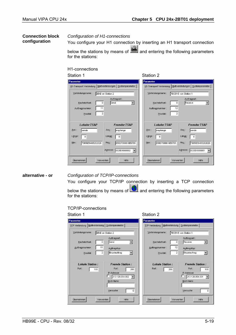
Manual VIPA CPU 24x Chapter 5 CPU 24x-2BT01 deployment
HB99E - CPU - Rev. 08/32 5-19
Configuration of H1-connections You configure your H1 connection by inserting an H1 transport connection
below the stations by means of and entering the following parameters for the stations: H1-connections Station 1 Station 2
Configuration of TCP/IP-connections You configure your TCP/IP connection by inserting a TCP connection
below the stations by means of and entering the following parameters for the stations: TCP/IP-connections Station 1 Station 2
Connection block configuration
alternative - or

Chapter 5 CPU 24x-2BT01 deployment Manual VIPA CPU 24x
5-20 HB99E - CPU - Rev. 08/32
Your network window should have the following contents:
You can transfer your configuration online via the network into the respective CP. Create the system structure as shown above and start both CPs. For the data transfer you must place both CPs into STOP status. The CP-portion of the CPU 24x NET can be changed to the STOP status
by means of the "Module transfer functions" . The CP 143 H1 / TCP/IP is places into the STOP condition by means of the RUN/STOP switch. Select the station to which you wish to transfer the configuration data in the network window of WinNCS and activate the module transfer function by
means of . Define the IP-address of the destination CP under INIT and transfer the respective configuration data into the CP by means of PC=>CP. On the CPU 24x NET it is mandatory that the command CP=>FLASH is issued when the transfer has been completed as your program would otherwise be erased again. Repeat the procedure above for station 2. In this case a transfer into the flash-ROM is not required. You can obtain details on the data transfer from the WinNCS manual under "Module transfer". This concludes the configuration of the CP side. The following pages contain information on the programming for the PLC side.
Transferring the configuration data into the CP
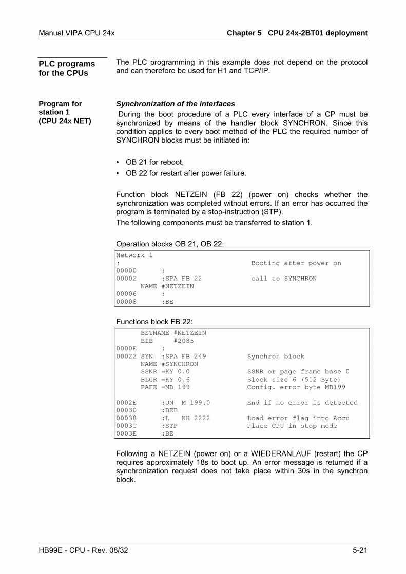
Manual VIPA CPU 24x Chapter 5 CPU 24x-2BT01 deployment
HB99E - CPU - Rev. 08/32 5-21
The PLC programming in this example does not depend on the protocol and can therefore be used for H1 and TCP/IP.
Synchronization of the interfaces During the boot procedure of a PLC every interface of a CP must be synchronized by means of the handler block SYNCHRON. Since this condition applies to every boot method of the PLC the required number of SYNCHRON blocks must be initiated in: • OB 21 for reboot, • OB 22 for restart after power failure. Function block NETZEIN (FB 22) (power on) checks whether the synchronization was completed without errors. If an error has occurred the program is terminated by a stop-instruction (STP). The following components must be transferred to station 1. Operation blocks OB 21, OB 22: Network 1 ; Booting after power on 00000 : 00002 :SPA FB 22 call to SYNCHRON NAME #NETZEIN 00006 : 00008 :BE
Functions block FB 22: BSTNAME #NETZEIN BIB #2085 0000E : 00022 SYN :SPA FB 249 Synchron block NAME #SYNCHRON SSNR =KY 0,0 SSNR or page frame base 0 BLGR =KY 0,6 Block size 6 (512 Byte) PAFE =MB 199 Config. error byte MB199 0002E :UN M 199.0 End if no error is detected 00030 :BEB 00038 :L KH 2222 Load error flag into Accu 0003C :STP Place CPU in stop mode 0003E :BE
Following a NETZEIN (power on) or a WIEDERANLAUF (restart) the CP requires approximately 18s to boot up. An error message is returned if a synchronization request does not take place within 30s in the synchron block.
PLC programs for the CPUs
Program for station 1 (CPU 24x NET)
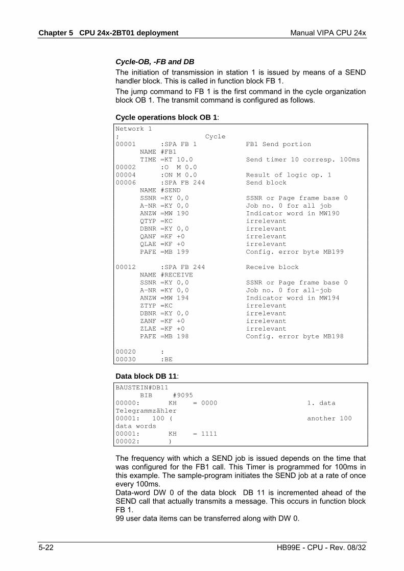
Chapter 5 CPU 24x-2BT01 deployment Manual VIPA CPU 24x
5-22 HB99E - CPU - Rev. 08/32
Cycle-OB, -FB and DB The initiation of transmission in station 1 is issued by means of a SEND handler block. This is called in function block FB 1. The jump command to FB 1 is the first command in the cycle organization block OB 1. The transmit command is configured as follows.
Cycle operations block OB 1: Network 1 ; Cycle 00001 :SPA FB 1 FB1 Send portion NAME #FB1 TIME =KT 10.0 Send timer 10 corresp. 100ms 00002 :O M 0.0 00004 :ON M 0.0 Result of logic op. 1 00006 :SPA FB 244 Send block NAME #SEND SSNR =KY 0,0 SSNR or Page frame base 0 A-NR =KY 0,0 Job no. 0 for all job ANZW =MW 190 Indicator word in MW190 QTYP =KC irrelevant DBNR =KY 0,0 irrelevant QANF =KF +0 irrelevant QLAE =KF +0 irrelevant PAFE =MB 199 Config. error byte MB199 00012 :SPA FB 244 Receive block NAME #RECEIVE SSNR =KY 0,0 SSNR or Page frame base 0 A-NR =KY 0,0 Job no. 0 for all-job ANZW =MW 194 Indicator word in MW194 ZTYP =KC irrelevant DBNR =KY 0,0 irrelevant ZANF =KF +0 irrelevant ZLAE =KF +0 irrelevant PAFE =MB 198 Config. error byte MB198 00020 : 00030 :BE
Data block DB 11: BAUSTEIN#DB11 BIB #9095 00000: KH = 0000 1. data Telegrammzähler 00001: 100 ( another 100 data words 00001: KH = 1111 00002: )
The frequency with which a SEND job is issued depends on the time that was configured for the FB1 call. This Timer is programmed for 100ms in this example. The sample-program initiates the SEND job at a rate of once every 100ms. Data-word DW 0 of the data block DB 11 is incremented ahead of the SEND call that actually transmits a message. This occurs in function block FB 1. 99 user data items can be transferred along with DW 0.
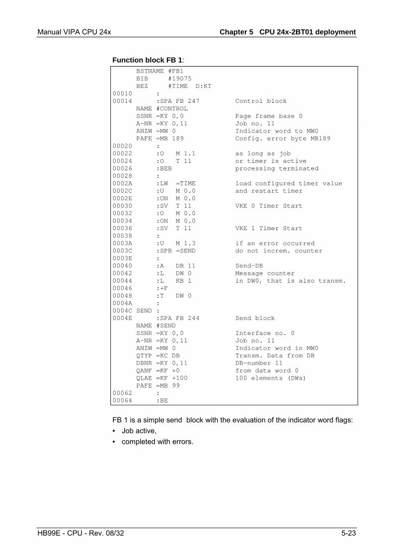
Manual VIPA CPU 24x Chapter 5 CPU 24x-2BT01 deployment
HB99E - CPU - Rev. 08/32 5-23
Function block FB 1: BSTNAME #FB1 BIB #19075 BEZ #TIME D:KT 00010 : 00014 :SPA FB 247 Control block NAME #CONTROL SSNR =KY 0,0 Page frame base 0 A-NR =KY 0,11 Job no. 11 ANZW =MW 0 Indicator word to MW0 PAFE =MB 189 Config. error byte MB189 00020 : 00022 :O M 1.1 as long as job 00024 :O T 11 or timer is active 00026 :BEB processing terminated 00028 : 0002A :LW =TIME load configured timer value 0002C :U M 0.0 and restart timer 0002E :UN M 0.0 00030 :SV T 11 VKE 0 Timer Start 00032 :O M 0.0 00034 :ON M 0.0 00036 :SV T 11 VKE 1 Timer Start 00038 : 0003A :U M 1.3 if an error occurred 0003C :SPB =SEND do not increm. counter 0003E : 00040 :A DB 11 Send-DB 00042 :L DW 0 Message counter 00044 :L KB 1 in DW0, that is also transm. 00046 :+F 00048 :T DW 0 0004A : 0004C SEND : 0004E :SPA FB 244 Send block NAME #SEND SSNR =KY 0,0 Interface no. 0 A-NR =KY 0,11 Job no. 11 ANZW =MW 0 Indicator word in MW0 QTYP =KC DB Transm. Data from DB DBNR =KY 0,11 DB-number 11 QANF =KF +0 from data word 0 QLAE =KF +100 100 elements (DWs) PAFE =MB 99 00062 : 00064 :BE
FB 1 is a simple send block with the evaluation of the indicator word flags: • Job active, • completed with errors.
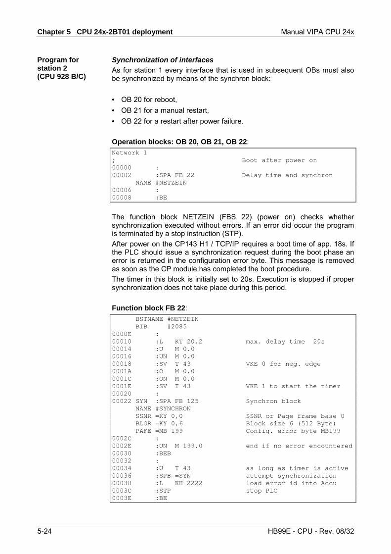
Chapter 5 CPU 24x-2BT01 deployment Manual VIPA CPU 24x
5-24 HB99E - CPU - Rev. 08/32
Synchronization of interfaces As for station 1 every interface that is used in subsequent OBs must also be synchronized by means of the synchron block: • OB 20 for reboot, • OB 21 for a manual restart, • OB 22 for a restart after power failure. Operation blocks: OB 20, OB 21, OB 22: Network 1 ; Boot after power on 00000 : 00002 :SPA FB 22 Delay time and synchron NAME #NETZEIN 00006 : 00008 :BE
The function block NETZEIN (FBS 22) (power on) checks whether synchronization executed without errors. If an error did occur the program is terminated by a stop instruction (STP). After power on the CP143 H1 / TCP/IP requires a boot time of app. 18s. If the PLC should issue a synchronization request during the boot phase an error is returned in the configuration error byte. This message is removed as soon as the CP module has completed the boot procedure. The timer in this block is initially set to 20s. Execution is stopped if proper synchronization does not take place during this period. Function block FB 22: BSTNAME #NETZEIN BIB #2085 0000E : 00010 :L KT 20.2 max. delay time 20s 00014 :U M 0.0 00016 :UN M 0.0 00018 :SV T 43 VKE 0 for neg. edge 0001A :O M 0.0 0001C :ON M 0.0 0001E :SV T 43 VKE 1 to start the timer 00020 : 00022 SYN :SPA FB 125 Synchron block NAME #SYNCHRON SSNR =KY 0,0 SSNR or Page frame base 0 BLGR =KY 0,6 Block size 6 (512 Byte) PAFE =MB 199 Config. error byte MB199 0002C : 0002E :UN M 199.0 end if no error encountered 00030 :BEB 00032 : 00034 :U T 43 as long as timer is active 00036 :SPB =SYN attempt synchronization 00038 :L KH 2222 load error id into Accu 0003C :STP stop PLC 0003E :BE
Program for station 2 (CPU 928 B/C)
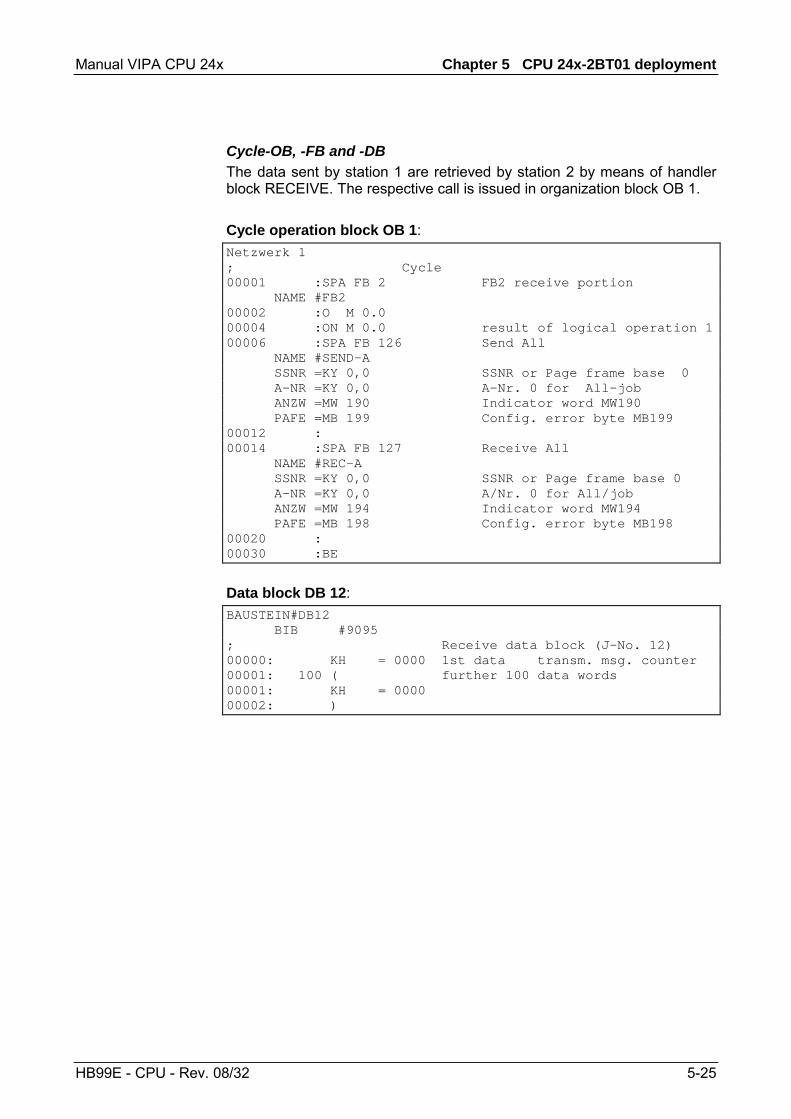
Manual VIPA CPU 24x Chapter 5 CPU 24x-2BT01 deployment
HB99E - CPU - Rev. 08/32 5-25
Cycle-OB, -FB and -DB The data sent by station 1 are retrieved by station 2 by means of handler block RECEIVE. The respective call is issued in organization block OB 1. Cycle operation block OB 1: Netzwerk 1 ; Cycle 00001 :SPA FB 2 FB2 receive portion NAME #FB2 00002 :O M 0.0 00004 :ON M 0.0 result of logical operation 1 00006 :SPA FB 126 Send All NAME #SEND-A SSNR =KY 0,0 SSNR or Page frame base 0 A-NR =KY 0,0 A-Nr. 0 for All-job ANZW =MW 190 Indicator word MW190 PAFE =MB 199 Config. error byte MB199 00012 : 00014 :SPA FB 127 Receive All NAME #REC-A SSNR =KY 0,0 SSNR or Page frame base 0 A-NR =KY 0,0 A/Nr. 0 for All/job ANZW =MW 194 Indicator word MW194 PAFE =MB 198 Config. error byte MB198 00020 : 00030 :BE
Data block DB 12: BAUSTEIN#DB12 BIB #9095 ; Receive data block (J-No. 12) 00000: KH = 0000 1st data transm. msg. counter 00001: 100 ( further 100 data words 00001: KH = 0000 00002: )
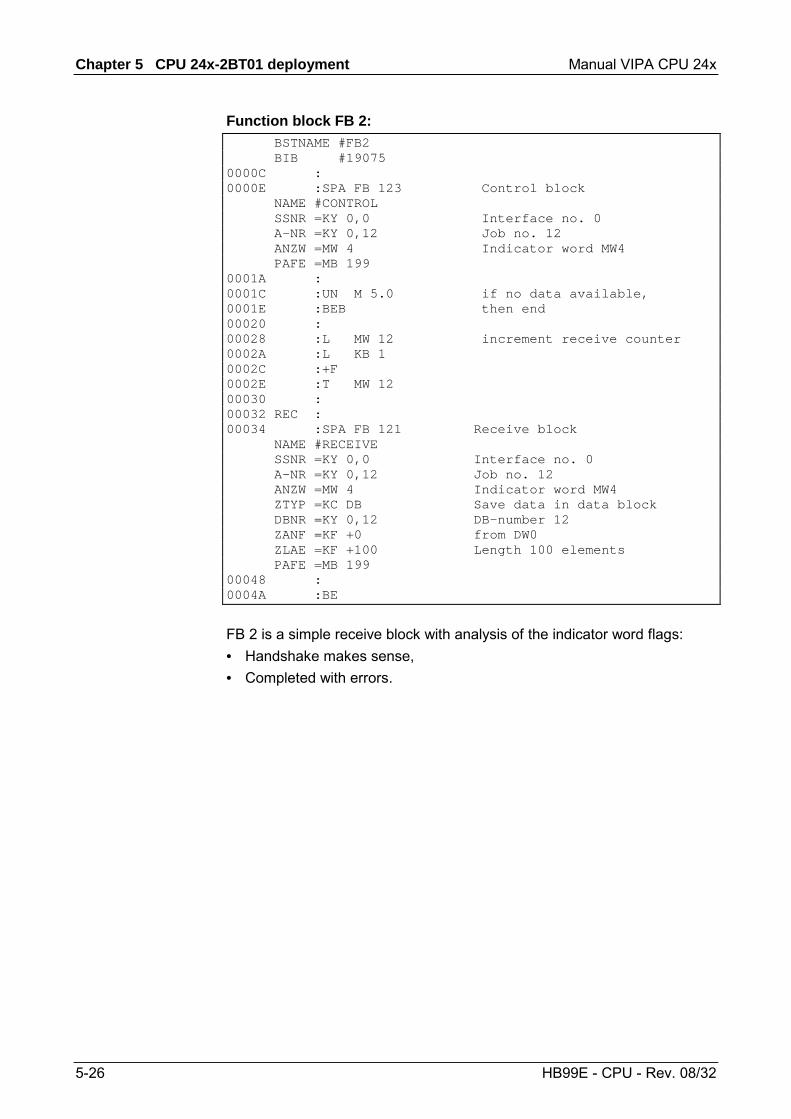
Chapter 5 CPU 24x-2BT01 deployment Manual VIPA CPU 24x
5-26 HB99E - CPU - Rev. 08/32
Function block FB 2: BSTNAME #FB2 BIB #19075 0000C : 0000E :SPA FB 123 Control block NAME #CONTROL SSNR =KY 0,0 Interface no. 0 A-NR =KY 0,12 Job no. 12 ANZW =MW 4 Indicator word MW4 PAFE =MB 199 0001A : 0001C :UN M 5.0 if no data available, 0001E :BEB then end 00020 : 00028 :L MW 12 increment receive counter 0002A :L KB 1 0002C :+F 0002E :T MW 12 00030 : 00032 REC : 00034 :SPA FB 121 Receive block NAME #RECEIVE SSNR =KY 0,0 Interface no. 0 A-NR =KY 0,12 Job no. 12 ANZW =MW 4 Indicator word MW4 ZTYP =KC DB Save data in data block DBNR =KY 0,12 DB-number 12 ZANF =KF +0 from DW0 ZLAE =KF +100 Length 100 elements PAFE =MB 199 00048 : 0004A :BE
FB 2 is a simple receive block with analysis of the indicator word flags: • Handshake makes sense, • Completed with errors.
Manual VIPA CPU 24x Chapter 5 CPU 24x-2BT01 deployment
HB99E - CPU - Rev. 08/32 5-27
When monitoring of connection jobs is required both the modules as well as the CPU must be programmed. The starting point is a set of configured modules and a PLC that was reset with the RUN/STO switch in position STOP. You must now load the above PLC programs into both CPUs. Start the programs by placing the respective RUN/STOP switch into the position RUN. At this point communications between the modules is established. This is indicated by the COMM-LED. Start the VIPA MC5-package on your PC and execute the following steps monitor the transmit job: • Go to the test menu from the main menu (F8). • Access the sub-menu "Steuern Variablen." (control of variables) by
means of "Steu.Var" (F5). The header line of the display mask contains the information on the displayed function, the degree of occupancy of the current page (in %) and the current number of pages (from 1 to 20). The mask is split into three columns. Into the "Operand" column you enter the process variables by editing or loading of a variable list. In the "Format" column you can enter changes depending on the type of operand.
• Enter the required data blocks (here DB 11) and data words (here DW 0 to DW 99) into the "Operand" column.
• User data can be entered from DW 1. For this purpose you place the cursor on "Wert" (value) and enter the value that you wish to transfer. In the example the “Wert” is "1111".
Monitoring the transfer with the MC5-package
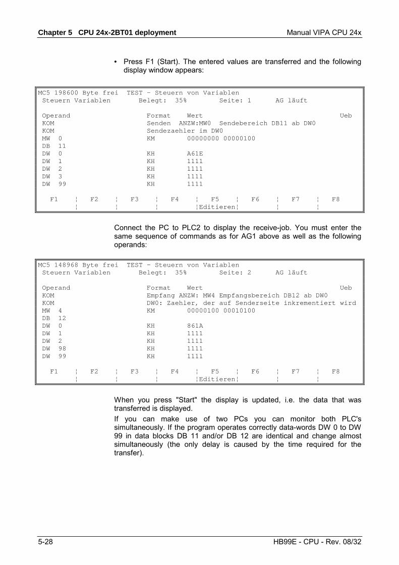
Chapter 5 CPU 24x-2BT01 deployment Manual VIPA CPU 24x
5-28 HB99E - CPU - Rev. 08/32
• Press F1 (Start). The entered values are transferred and the following display window appears:
MC5 198600 Byte frei TEST - Steuern von Variablen Steuern Variablen Belegt: 35% Seite: 1 AG läuft Operand Format Wert Ueb KOM Senden ANZW:MW0 Sendebereich DB11 ab DW0 KOM Sendezaehler im DW0 MW 0 KM 00000000 00000100 DB 11 DW 0 KH A61E DW 1 KH 1111 DW 2 KH 1111 DW 3 KH 1111 DW 99 KH 1111 F1 ¦ F2 ¦ F3 ¦ F4 ¦ F5 ¦ F6 ¦ F7 ¦ F8 ¦ ¦ ¦ ¦Editieren¦ ¦ ¦
Connect the PC to PLC2 to display the receive-job. You must enter the same sequence of commands as for AG1 above as well as the following operands:
MC5 148968 Byte frei TEST - Steuern von Variablen Steuern Variablen Belegt: 35% Seite: 2 AG läuft Operand Format Wert Ueb KOM Empfang ANZW: MW4 Empfangsbereich DB12 ab DW0 KOM DW0: Zaehler, der auf Senderseite inkrementiert wird MW 4 KM 00000100 00010100 DB 12 DW 0 KH 861A DW 1 KH 1111 DW 2 KH 1111 DW 98 KH 1111 DW 99 KH 1111 F1 ¦ F2 ¦ F3 ¦ F4 ¦ F5 ¦ F6 ¦ F7 ¦ F8 ¦ ¦ ¦ ¦Editieren¦ ¦ ¦
When you press "Start" the display is updated, i.e. the data that was transferred is displayed. If you can make use of two PCs you can monitor both PLC's simultaneously. If the program operates correctly data-words DW 0 to DW 99 in data blocks DB 11 and/or DB 12 are identical and change almost simultaneously (the only delay is caused by the time required for the transfer).
Manual VIPA CPU 24x Chapter 5 CPU 24x-2BT01 deployment
HB99E - CPU - Rev. 08/32 5-29
Boot behavior
When the power supply is turned on the CPU and the CP execute the respective BIOS routine (hardware and driver initialization and memory test). While the CPU determines the modules that have been installed on the back panel bus and while it loads the application program the CP starts the page frame administration routine. After app. 15s the CP waits for the synchronization request from the CPU. In this condition data communications with the PLC is inhibited and it is only released after synchronization. The boot time of the CPU 24x NET including the CP amounts to appr. 18s.
With every status change from STOP to RUN as well as from RUN to STOP back to RUN the CPU24x NET performs a cold-/warm start. All connections are cleared and reestablished after the CP job has booted. These status change requests can be caused by three different sources: • Resynchroniszation of a CP by the synchron-HTBs of the CPU (warm
start) after it has already been synchronized, • STOP/START-function of the configuration tool WinNCS (warm start), • Reset-All (warm start).
Status after CP boot-up

Chapter 5 CPU 24x-2BT01 deployment Manual VIPA CPU 24x
5-30 HB99E - CPU - Rev. 08/32
System properties of the CPU 24x NET
System properties of a CP must not be regarded as restrictions or equated with bad reactions. Certain functions can not be provided or are not desired when the overall system is taken into account.
The boot time of the CP-portion of the CPU 24x NET is app. 18 seconds. The integrated SYNCHRON block (delay time 30s) caters for this boot time.
• Jobs with a priority 0/1 can transmit and/or receive a maximum quantity of data as defined by the SYNCHRON-HTB. Jobs of this priority are not blocked. This results in a maximum data transfer rate of 512 bytes per job for a block-size of 255 (also refer to block-size).
• RECEIVE jobs that are mapped to the communication-type of broadcast cannot receive all data-messages from a fast cyclic transmitter. Messages that have not been received are discarded.
• The default length (-1, 0xFFFF) is not permitted for the ORG format length, i.e. the user must define the exact length of the data that must be received.
• Jobs with a priority of 1 can send and/or receive a maximum quantity of data as defined by the SYNCHRON-HTB. Jobs of this priority are not blocked. This results in a maximum data transfer rate of 512 bytes per job for a block size of 255 (see also block size).
• RECEIVE-jobs that mapped to communication type UDP cannot receive all data messages from a fast cyclic station. Messages that have not been received are discarded.
The TCP/IP protocol stack has a global buffer-pool where the receive and transmit buffers are located. This is where system collisions can occur if: • Data for a receive-job is not collected. After a period of time a lack of
resources will occur and the other connections will terminate connections. It is only possible to re-establish proper communications when the receive buffers of one connection have been released (connection terminated) or when the data has been retrieved by means of the RECEIVE-HTBs.
Note
General
Note only for H1
Only for TCP/IP
Manual VIPA CPU 24x Chapter 5 CPU 24x-2BT01 deployment
HB99E - CPU - Rev. 08/32 5-31
• one or more cyclic stations place a load on a CP. When resource bottlenecks are encountered the CP can also initiate the termination of connections.
• A station transmits two or more messages and the receiver did not have a chance to accept them then the reception of the unknown data type would cause collisions in the receiver. However, the CP prevents this. The PLC-application requires a defined size for the reception of data and the default or wild-card length is not permitted. The size of the receive stat of Prio1 - RECEIVE jobs is defined implicitly by the pre-defined block-size (16, 32, 64, 128, 256, 512 bytes).
• VIPA recommends the use of acknowledgment messages on the user-level to ensure that data transfers are one hundred percent safe.

Chapter 5 CPU 24x-2BT01 deployment Manual VIPA CPU 24x
5-32 HB99E - CPU - Rev. 08/32
Communication links to foreign systems
The organization-format is the abbreviated description of a data-source or a data-destination in a PLC environment. The following table lists the available ORG-formats. In the case of READ and WRITE the ORG-block is optional. The ERW-identifier is used for the addressing of data blocks. In this case the data block number is entered into this identifier. The start address and quantity provide the address for the memory area and they are stored in HIGH-/LOW- format (Motorola-formatted addresses)
Description Type Range ORG identifier BYTE 1..x ERW identifier BYTE 1..255 Start address HILOWORD 0..y Quantity HILOWORD 1..z
The following table contains a list of available ORG formats. The "length" must not be entered as -1 (FFFFh).
ORG identifier 01h-04h AG area DB MB EB AB ORG identifier 01h 02h 03h 04h Description Source/destination data
from/into data block in main memory.
source/destination data from/into flag area.
Source/destination data from/into process image of the inputs (PAE).
source/destination data from/into process image of the outputs (PAA).
DBNR valid range:
DB from where the source data is retrieved or to where the destination data is trans-ferred. 1...255
irrelevant irrelevant irrelevant
Start address Significance valid range:
DW-No. from where the data is retrieved or where data is saved. 1...2047
MB- No. from where the data is retrieved or where data is saved. 0...255
EB-No. from where the data is retrieved or where data is saved. 0...127
AB-No. from where the data is retrieved or where data is saved. 0...127
Quantity Significance valid range:
Length of the source/destination data -block in words. 1...2048
Length of the source/destination data block in words. 1...256
Length of the source/destination data block in words. 1...128
Length of the source/destination data block in words. 1...128
ORG-format
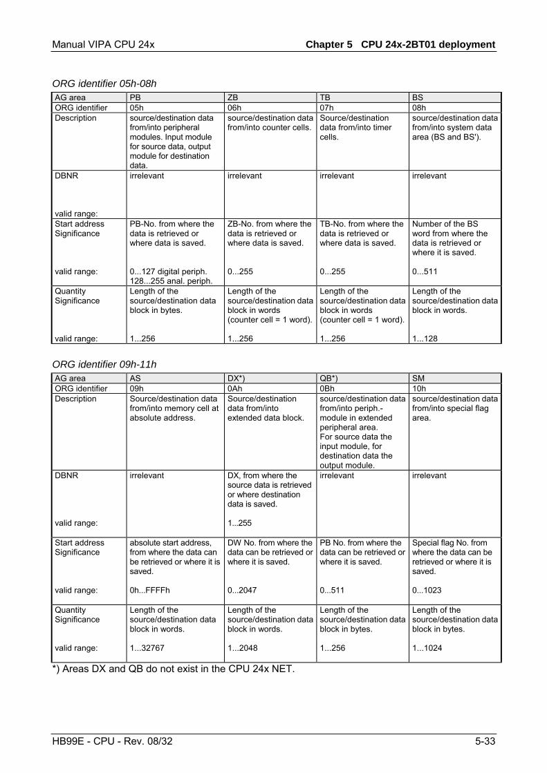
Manual VIPA CPU 24x Chapter 5 CPU 24x-2BT01 deployment
HB99E - CPU - Rev. 08/32 5-33
ORG identifier 05h-08h
AG area PB ZB TB BS ORG identifier 05h 06h 07h 08h Description source/destination data
from/into peripheral modules. Input module for source data, output module for destination data.
source/destination data from/into counter cells.
Source/destination data from/into timer cells.
source/destination data from/into system data area (BS and BS').
DBNR valid range:
irrelevant irrelevant irrelevant irrelevant
Start address Significance valid range:
PB-No. from where the data is retrieved or where data is saved. 0...127 digital periph. 128...255 anal. periph.
ZB-No. from where the data is retrieved or where data is saved. 0...255
TB-No. from where the data is retrieved or where data is saved. 0...255
Number of the BS word from where the data is retrieved or where it is saved. 0...511
Quantity Significance valid range:
Length of the source/destination data block in bytes. 1...256
Length of the source/destination data block in words (counter cell = 1 word). 1...256
Length of the source/destination data block in words (counter cell = 1 word). 1...256
Length of the source/destination data block in words. 1...128
ORG identifier 09h-11h AG area AS DX*) QB*) SM ORG identifier 09h 0Ah 0Bh 10h Description Source/destination data
from/into memory cell at absolute address.
Source/destination data from/into extended data block.
source/destination data from/into periph.-module in extended peripheral area. For source data the input module, for destination data the output module.
source/destination data from/into special flag area.
DBNR valid range:
irrelevant DX, from where the source data is retrieved or where destination data is saved. 1...255
irrelevant irrelevant
Start address Significance valid range:
absolute start address, from where the data can be retrieved or where it is saved. 0h...FFFFh
DW No. from where the data can be retrieved or where it is saved. 0...2047
PB No. from where the data can be retrieved or where it is saved. 0...511
Special flag No. from where the data can be retrieved or where it is saved. 0...1023
Quantity Significance valid range:
Length of the source/destination data block in words. 1...32767
Length of the source/destination data block in words. 1...2048
Length of the source/destination data block in bytes. 1...256
Length of the source/destination data block in bytes. 1...1024
*) Areas DX and QB do not exist in the CPU 24x NET.

Chapter 5 CPU 24x-2BT01 deployment Manual VIPA CPU 24x
5-34 HB99E - CPU - Rev. 08/32
For every READ and WRITE the CP generates PLC-headers for request messages and for acknowledgment messages. Normally the length of these headers is 16bytes and they have the following structure:
Structure of PLC header
for WRITE Acknowledgment message
System identifier ="S" ="5" Length of header =16d Ident.OP-code =01 Length of OP-code =03 OP-Code =04 Ack. block =0Fh Length of Ack-block =03 Error No. =Nr. Dummy block =FFh Length of dummy bl. =07
not used
Request message
System identifier ="S" ="5" Length of header =16d Ident.OP-code =01 Length of OP-code =03 OP-Code =03 ORG-block =03 Length of ORG-block =08 ORG identifier DBNR Start address H L Length H L Dummy block =FFh Length of dummy bl. =02
Up to 64K data but only if error no.=0
Acknowledgment message
System identifier ="S" ="5" Length of header =16d Ident.OP-code =01 Length of OP-code =03 OP-Code =06 Ack. block =0Fh Length of Ack-block =03 Error No. =Nr. Dummy block =FFh Length Dummy block =07
not used Up to 64K data but only if error no.=0
for READ Request message
System identifier ="S" ="5" Length of header =16d Ident.OP-code =01 Length of OP-code =03 OP-Code =05 ORG-block =03 Length of ORG-block =08 ORG identifier DBNR Start address H L Length H L Dummy block =FFh Length of dummy block =02
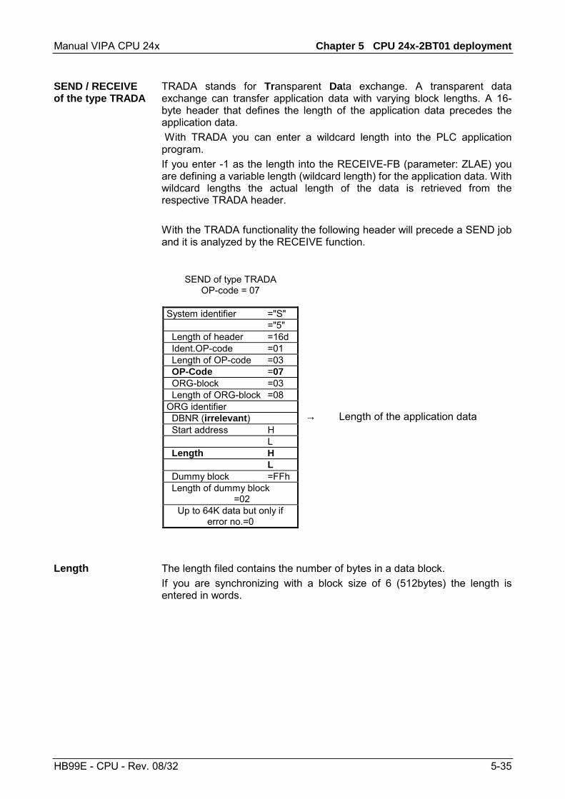
Manual VIPA CPU 24x Chapter 5 CPU 24x-2BT01 deployment
HB99E - CPU - Rev. 08/32 5-35
TRADA stands for Transparent Data exchange. A transparent data exchange can transfer application data with varying block lengths. A 16-byte header that defines the length of the application data precedes the application data. With TRADA you can enter a wildcard length into the PLC application program. If you enter -1 as the length into the RECEIVE-FB (parameter: ZLAE) you are defining a variable length (wildcard length) for the application data. With wildcard lengths the actual length of the data is retrieved from the respective TRADA header. With the TRADA functionality the following header will precede a SEND job and it is analyzed by the RECEIVE function.
→ Length of the application data
The length filed contains the number of bytes in a data block. If you are synchronizing with a block size of 6 (512bytes) the length is entered in words.
SEND / RECEIVE of the type TRADA
SEND of type TRADA OP-code = 07
System identifier ="S" ="5" Length of header =16d Ident.OP-code =01 Length of OP-code =03 OP-Code =07 ORG-block =03 Length of ORG-block =08 ORG identifier DBNR (irrelevant) Start address H L Length H L Dummy block =FFh Length of dummy block =02
Up to 64K data but only if error no.=0
Length
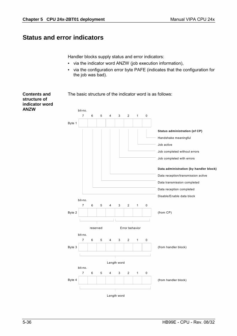
Chapter 5 CPU 24x-2BT01 deployment Manual VIPA CPU 24x
5-36 HB99E - CPU - Rev. 08/32
Status and error indicators
Handler blocks supply status and error indicators: • via the indicator word ANZW (job execution information), • via the configuration error byte PAFE (indicates that the configuration for
the job was bad).
The basic structure of the indicator word is as follows:
7 6 5 4 3 2 1 0
bit-no.
Status administration (of CP)
Handshake meaningful
Job active
Job completed without errors
Job completed with errors
Data administration (by handler block)
Data reception/transmission active
Data transmission completed
Data reception completed
Disable/Enable data block
7 6 5 4 3 2 1 0
bit-no.
Error behaviorreserved
7 6 5 4 3 2 1 0
bit-no.
Length word
7 6 5 4 3 2 1 0
bit-no.
Length word
Byte 1
Byte 2
Byte 3
Byte 4
(from handler block)
(from handler block)
(from CP)
Contents and structure of indicator word ANZW
Manual VIPA CPU 24x Chapter 5 CPU 24x-2BT01 deployment
HB99E - CPU - Rev. 08/32 5-37
These bits are used to indicate whether a job has been started, whether errors have occurred or whether a job is blocked, for instance if the virtual connection does not exist. Bit 0: handshake makes sense Set: by the interface, similar to the "clear"-indicator in the job-
bit. The indicator “Handshake makes sense” (=1) is used by the RECEIVE block. (message available for PRIO 1 or RECEIVE-initiation permitted for PRIO 2/3).
Analysis: by the RECEIVE block: RECEIVE will initiate a handshake with the CP only if the bit is set. By the application: For a RECEIVE request (check whether a message exists for PRIO 1).
Bit 1: job active Set: by the interface, when job was transferred to CP. Reset: by the interface, when a job has been completed (e.g.
acknowledgment received). Analysis: by the handler blocks: a new job can only be issued if the
"old" job has been completed. By the user: to determine whether it makes sense to
trigger a new job. Bit 2: job completed without errors Set: by the interface, when the respective job was completed
without errors. Reset: by the interface, when the job is triggered again. Analysis: by the user, to check whether the job was completed
without errors. Bit 3: job completed with errors Set: by the interface, when the respective job was completed
with errors. The reason for the error is coded in the high part of the indicator word.
Reset: by the interface, when the job was triggered again. Analysis: by the user: to check whether the job was completed with
errors or. The high byte of the indicator word contains the reason for the error if the identifier "Job completed with error" is set.
Status administration byte 1 bit 0 ... bit 3
Chapter 5 CPU 24x-2BT01 deployment Manual VIPA CPU 24x
5-38 HB99E - CPU - Rev. 08/32
These contain the code indicating whether the data transfer for the job is still active or whether the process of retrieving or delivering data has been completed. The "Enable / Disable" bit can be used to inhibit the data transfer for the job. (Disable = 1; Enable = 0). Bit 4: Data retrieval / data delivery active Set: by handler blocks SEND, RECEIVE, when the
transfer/receipt procedure was started for a job, e.g. when data is transferred by means of the ALL-function (replacement for DMA) and the function is started by SEND-DIREKT.
Reset: by handler blocks SEND, RECEIVE, when the data exchange for a job has been completed (last sub-block has been transferred).
Analysis: by the user: the contents of the respective record of the job must not be changed by the user while it is being transferred CP<< >>AG. This is not critical for PRIO 0/1 jobs since these transfers can be completed in a single block cycle. However, larger quantities of data can only be exchanged in blocks. The respective blocking mechanism is distributed over multiple cycles of the PLC. To ensure data consistency it is necessary that you check whether the data block is being transferred or not before modification of its the contents.
BIT 5: Data transfer completed Set: by handler block SEND, when the data for a job has been
delivered. Reset: by handler block SEND, when a data transfer was started
for a new job (new trigger). By the user: when the analysis has been completed (edge generation).
Analysis: By the user: this bit can be used to determine whether the data record of the job has already been transferred to the CP or at what time a new data record can be provided for an active job (e.g. cyclic transfers).
Bit 6: Data reception completed Set: by handler block RECEIVE, when the reception of data for
the respective job has been completed. Reset: by handler block RECEIVE, when the transfer of data for
a new job (new trigger) into the PLC has been initiated. By the user, when the analysis is started (edge generation).
Analysis: by the user: this bit can be used to determine whether a data record of a job has been transferred to the PLC or at what time a data record of an active job was transferred into the PLC.
Data administration byte 1 bit 4 ... bit 7
Manual VIPA CPU 24x Chapter 5 CPU 24x-2BT01 deployment
HB99E - CPU - Rev. 08/32 5-39
Bit 7: Disable / Enable data block Set: by the user, to inhibit write access to an area from the
RECEIVE-block or to inhibit read access to an area from the SEND-block (only for the 1st data block).
Reset: by the user, to enable access to the respective data block. Analysis: by handler blocks SEND and RECEIVE. If bit 7 is set the
blocks will not start a data transfer but instead they will return an error to the CP.
These bits contain the error indicators for the job. These error indicators are only valid if the bit "Job completed with error" is set in the status bit. The following error messages can be issued: 0 No error If the bit "Job completed with error" is set then the CP143 H1 / TCP/IP was forced to re-establish the connection, e.g. following a warm restart or a RESET. 1 Bad Q/ZTYP at the HTB The job was configured with an incorrect TYP-identifier. 2 Area does not exist in the PLC An incorrect DB (DBNR) was configured when the job was initiated. 3 Overflow in PLC The sum of Q/ZANF and Q/ZLAE exceeds the ^limits of the area. For
data blocks this limit is defined by the block size. In case of flags, timers, counters etc. the area limit depends on the respective PLC.
4 QVZ-error in PLC The source and/or destination parameters specified for the PLC define
an area of memory that is defective or that does not contain any memory. The QVZ-error can only occur with Q/ZTYP AS, PB, QB or when memory has failed.
5 Error in the indicator word The configured indicator word can not be processed. This error occurs
when ANZW is accompanied by a data word or a double word that is no longer located in the specified data block, i.e. DB too small or it does not exist.
6 No valid ORG-format The destination and/or source for the data was not specified in the
handler block (Q/TYP="NN") nor was it specified in the connection block. 7 Reserved
Error handling byte 2 bit 0 ... bit 3

Chapter 5 CPU 24x-2BT01 deployment Manual VIPA CPU 24x
5-40 HB99E - CPU - Rev. 08/32
8 No open transport connections available The transport connection capacities have been exceeded. You must
remove unused connections. 9 Remote error An error occurred in the communication partner during a READ/WRITE
job. A Connection error The connection required for a job has not or not yet been established.
This error disappears as soon as the connection is possible. In the event that all the connections of the CP are interrupted you should suspect that the module or the bus cable are defective. This error can also be caused by a faulty configuration, e.g. incorrect addressing.
B Handshake error This could be a system error or the specified data block size was too
large. C Triggering error The job was started by means of an incorrect handler block or the data
block supplied was too large. D Termination after RESET These are operating indicators. In case of priority 1 and 2 the connection
is interrupted and it will be re-established as soon as the communication partner is ready for a new connection. In case of priority 3 connections the respective connection has been cleared, however, it is possible to re-initiate the connection.
E Job with bootstrap functionality This is an operating indicator. The respective job is a READ/WRITE-
PASSIV and it can not be started from the PLC. F Job does not exist The job that was addressed was not configured on the CP143 H1 /
TCP/IP. This error can occur when the SSNR/A-NR combination in the handler module is bad or if a connection block has not been entered.
Bits 4 to 7 of byte 2 are reserved for future expansion.
Manual VIPA CPU 24x Chapter 5 CPU 24x-2BT01 deployment
HB99E - CPU - Rev. 08/32 5-41
The handler blocks (SEND, RECEIVE) store the die quantity of data that has already been transferred for the respective job, i.e. in the case of receive jobs the quantity of data that has been received and for transmit jobs the quantity of data that has already been transmitted. Write: By SEND, RECEIVE while data is being transferred. The
"length-word" is calculated from: current qty. transf. + qty. of previously transferred data Reset: By overwrite or with every new SEND, RECEIVE, FETCH.
If the bit "Job completed without error" or "Data transmission/-reception occurred" is set the “length word” contains the up to date length of the source and/or destination. When the bit "Job completed with error" is set the length word contains the quantity of data that was transferred up to the time that the error occurred.
This section contains important status and error messages that can appear in the "indicator word". These are available as "HEX"-patterns similar to the ones that may be observed by means of the status / control-Var-Test-function of the PG in the PLC. X indicates "undefined" or "irrelevant"; No. is the error number. Indicator word: X F X A Error indicator "F" implies that the respective job was not defined on the CP 143. Status indicator A inhibits the job (for SEND / FETCH and RECEIVE). Indicator word: X A X A Error indicator "A" shows that connection for the communication job has not or not yet been established. Status indicator "A" inhibits both the SEND as well as the RECEIVE and the FETCH. Indicator word: X 0 X 8 The connection was re-established (e.g. after a CP-warm-start), SEND is enabled (SEND communication task). Indicator word: X 0 X 9 The connection has been reestablished, RECEIVE is enabled. (RECEIVE communication task). Indicator word: X 0 2 4 SEND was processed without errors, the data has been transferred successfully. Indicator word: X 0 4 5 RECEIVE was completed without errors, the data has arrived at the PLC.
Length word byte 3 ... byte 4
Important status and error indicators in the CPU 24x NET
Available indicator words
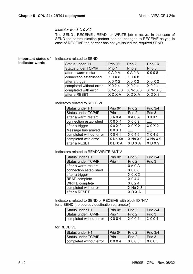
Chapter 5 CPU 24x-2BT01 deployment Manual VIPA CPU 24x
5-42 HB99E - CPU - Rev. 08/32
Indicator word: X 0 X 2 The SEND-, RECEIVE-, READ- or WRITE job is active. In the case of SEND the communication partner has not changed to RECEIVE as yet. In case of RECEIVE the partner has not yet issued the required SEND.
Indicators related to SEND Status under H1 Prio 0/1 Prio 2 Prio 3/4 Status under TCP/IP Prio 1 Prio 2 Prio 3 after a warm restart 0 A 0 A 0 A 0 A 0 0 0 8 connection established X 0 X 8 X 0 X 8 ..... after a trigger X 0 X 2 X 0 X 2 X 0 X 2 completed without error X 0 2 4 X 0 2 4 X 0 2 4 completed with error X No X 8 X No X 8 X No X 8 after a RESET X D X A X D X A X D X 8
Indicators related to RECEIVE
Status under H1 Prio 0/1 Prio 2 Prio 3/4 Status under TCP/IP Prio 1 Prio 2 Prio 3 after a warm restart 0 A 0 A 0 A 0 A 0 0 0 1 connection established X 0 X 4 X 0 0 9 ..... after a trigger X 0 X 2 X 0 X 2 X 0 X 2 Message has arrived X 0 X 1 ..... ..... completed without error X 0 4 1 X 0 4 5 X 0 4 5 completed with error X No X8 X No X 9 X No X 9 after a RESET X D X A X D X A X D X 9
Indicators related to READ/WRITE-AKTIV
Status under H1 Prio 0/1 Prio 2 Prio 3/4 Status under TCP/IP Prio 1 Prio 2 Prio 3 after a warm restart 0 A 0 A connection established X 0 0 8 after a trigger X 0 X 2 READ complete X 0 4 4 WRITE complete X 0 2 4 completed with error X No X 8 after a RESET X D X A
Indicators related to SEND or RECEIVE with block ID "NN" for a SEND (no source / destination parameter)
Status under H1 Prio 0/1 Prio 2 Prio 3/4 Status under TCP/IP Prio 1 Prio 2 Prio 3 completed without error X 0 0 4 X 0 0 4 X 0 0 4
for RECEIVE
Status under H1 Prio 0/1 Prio 2 Prio 3/4 Status under TCP/IP Prio 1 Prio 2 Prio 3 completed without error X 0 0 4 X 0 0 5 X 0 0 5
Important states of indicator words

Manual VIPA CPU 24x Chapter 5 CPU 24x-2BT01 deployment
HB99E - CPU - Rev. 08/32 5-43
The PAFE is set when the handler block has detected a configuration error.
7 6 5 4 3 2 1 0
bit-no.
0 = no error1 = error
not used
Error number
Error numbers: 0 no error 1 invalid ORG-format 2 area does not exist 3 size of area too small 4 QVZ error (delayed acknowledgment) 5 bad Indicator word 6 no source/destination parameters for SEND / RECEIVE ALL 7 interface does not exist 8 interface error 9 interface overloaded A not used B invalid job number ANR C interface not acknowledged and/or enabled D not allocated E not allocated F not allocated
PAFE configuration error byte
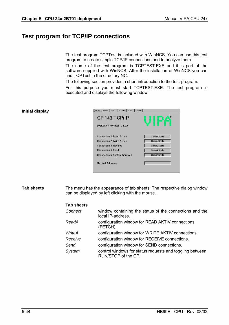
Chapter 5 CPU 24x-2BT01 deployment Manual VIPA CPU 24x
5-44 HB99E - CPU - Rev. 08/32
Test program for TCP/IP connections
The test program TCPTest is included with WinNCS. You can use this test program to create simple TCP/IP connections and to analyze them. The name of the test program is TCPTEST.EXE and it is part of the software supplied with WinNCS. After the installation of WinNCS you can find TCPTest in the directory NC. The following section provides a short introduction to the test-program. For this purpose you must start TCPTEST.EXE. The test program is executed and displays the following window:
The menu has the appearance of tab sheets. The respective dialog window can be displayed by left clicking with the mouse. Tab sheets Connect window containing the status of the connections and the
local IP-address. ReadA configuration window for READ AKTIV connections
(FETCH). WriteA configuration window for WRITE AKTIV connections. Receive configuration window for RECEIVE connections. Send configuration window for SEND connections. System control windows for status requests and toggling between
RUN/STOP of the CP.
Initial display
Tab sheets
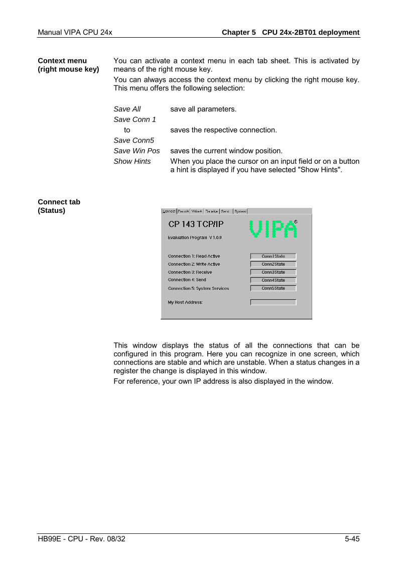
Manual VIPA CPU 24x Chapter 5 CPU 24x-2BT01 deployment
HB99E - CPU - Rev. 08/32 5-45
You can activate a context menu in each tab sheet. This is activated by means of the right mouse key. You can always access the context menu by clicking the right mouse key. This menu offers the following selection: Save All save all parameters. Save Conn 1 to saves the respective connection. Save Conn5 Save Win Pos saves the current window position. Show Hints When you place the cursor on an input field or on a button
a hint is displayed if you have selected "Show Hints".
This window displays the status of all the connections that can be configured in this program. Here you can recognize in one screen, which connections are stable and which are unstable. When a status changes in a register the change is displayed in this window. For reference, your own IP address is also displayed in the window.
Context menu (right mouse key)
Connect tab (Status)
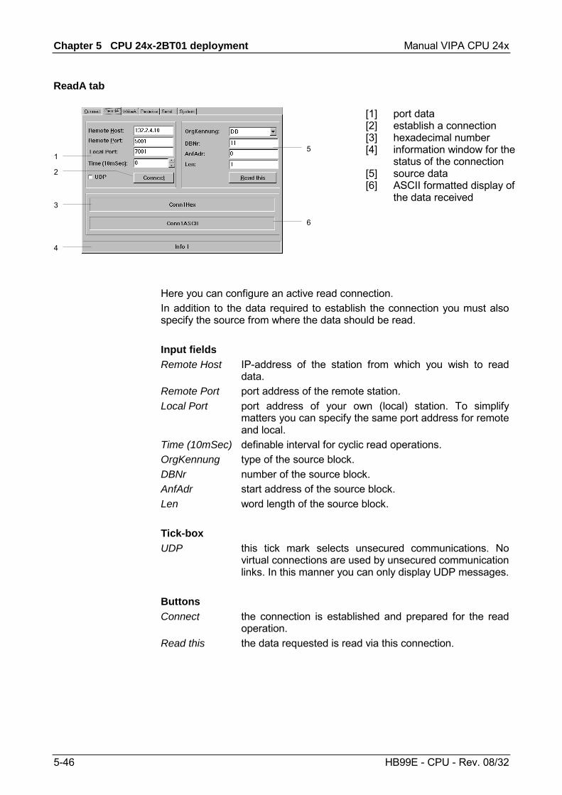
Chapter 5 CPU 24x-2BT01 deployment Manual VIPA CPU 24x
5-46 HB99E - CPU - Rev. 08/32
1
3
4
5
6
2
Here you can configure an active read connection. In addition to the data required to establish the connection you must also specify the source from where the data should be read. Input fields Remote Host IP-address of the station from which you wish to read
data. Remote Port port address of the remote station. Local Port port address of your own (local) station. To simplify
matters you can specify the same port address for remote and local.
Time (10mSec) definable interval for cyclic read operations. OrgKennung type of the source block. DBNr number of the source block. AnfAdr start address of the source block. Len word length of the source block. Tick-box UDP this tick mark selects unsecured communications. No
virtual connections are used by unsecured communication links. In this manner you can only display UDP messages.
Buttons Connect the connection is established and prepared for the read
operation. Read this the data requested is read via this connection.
ReadA tab
[1] port data [2] establish a connection [3] hexadecimal number [4] information window for the
status of the connection [5] source data [6] ASCII formatted display of
the data received

Manual VIPA CPU 24x Chapter 5 CPU 24x-2BT01 deployment
HB99E - CPU - Rev. 08/32 5-47
1
3
4
6
7
5
2
[1] [2] [3]
[4]
[5]
[6] [7]
port data establish a connection transfer the data via the connection result-code of the write job information window for the status of the connection source data ASCII-text that must be transferred to the CP
This is where you activate an active write connection. In the same way as for the READ active command you declare the destination block where the data must be transferred in addition to the data required for establishing the connection. Input fields Remote Host IP-Address of the station where to which you wish to write
the data. Remote Port port address of the remote station. Local Port port address of your own (local) station. To simplify
matters you can specify the same port address for remote and local.
Time (10mSec) definable interval for cyclic write operations. The minimum timer value for cyclic writes is 5.
OrgKennung type of destination block. DBNr number of the destination block. AnfAdr start address of destination block. Len word length of destination block. Tick-box UDP this tick mark selects unsecured communications. No
virtual connections are used by unsecured communication links. In this manner you can only display UDP messages.
Buttons Connect the connection is established and prepared for the write
operation. Write this data entered into the ASCII field is transferred to the CP
via the connection that was established by means of Connect.
WriteA tab
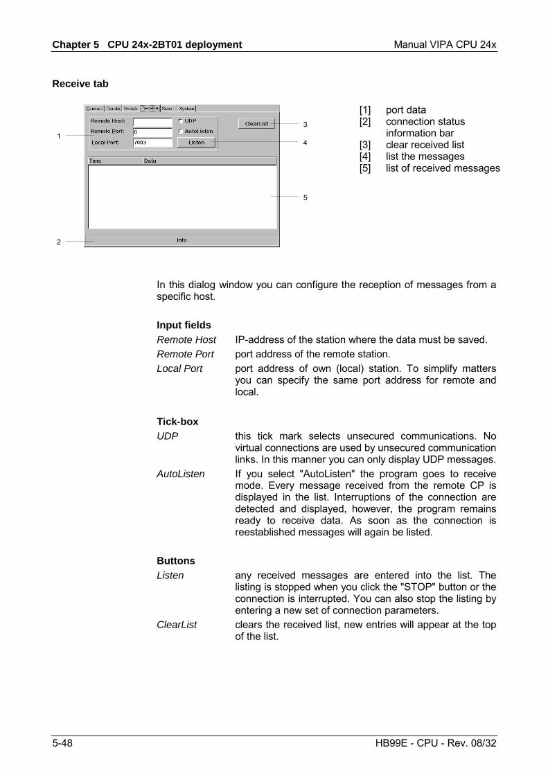
Chapter 5 CPU 24x-2BT01 deployment Manual VIPA CPU 24x
5-48 HB99E - CPU - Rev. 08/32
13
5
2
4
[1] [2]
[3] [4] [5]
port data connection status information bar clear received list list the messages list of received messages
In this dialog window you can configure the reception of messages from a specific host. Input fields Remote Host IP-address of the station where the data must be saved. Remote Port port address of the remote station. Local Port port address of own (local) station. To simplify matters
you can specify the same port address for remote and local.
Tick-box UDP this tick mark selects unsecured communications. No
virtual connections are used by unsecured communication links. In this manner you can only display UDP messages.
AutoListen If you select "AutoListen" the program goes to receive mode. Every message received from the remote CP is displayed in the list. Interruptions of the connection are detected and displayed, however, the program remains ready to receive data. As soon as the connection is reestablished messages will again be listed.
Buttons Listen any received messages are entered into the list. The
listing is stopped when you click the "STOP" button or the connection is interrupted. You can also stop the listing by entering a new set of connection parameters.
ClearList clears the received list, new entries will appear at the top of the list.
Receive tab

Manual VIPA CPU 24x Chapter 5 CPU 24x-2BT01 deployment
HB99E - CPU - Rev. 08/32 5-49
1
6
5
73
2
4
[1] [2] [3]
[4]
[5]
[6] [7]
port data establish a connection transfer data via the connection list of transmitted messages information bar for the connection status clear the list of messagesASCII-text that must be transferred to the CP
You can use this dialog window to send a message to a specific host. Input fields Remote Host IP-address of the station where the data must be saved. Remote Port port address of the remote station. Local Port port address of own (local) station. To simplify matters
you can specify the same port address for remote and local.
Time (10mSec) definable interval for cyclic write operations. The minimum timer value for cyclic writes is 5.
Tick-box UDP this tick mark selects unsecured communications. No
virtual connections are used by unsecured communication links. In this manner you can only display UDP messages.
Buttons Connect the connection is established and prepared for the write
operation. Send this data entered into the ASCII field is transferred to the CP
via the connection that was established by means of Connect.
Send tab
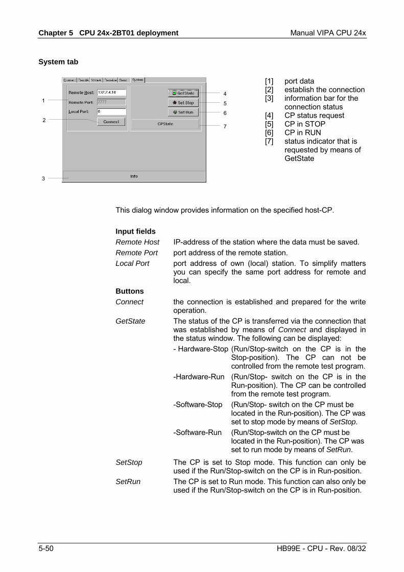
Chapter 5 CPU 24x-2BT01 deployment Manual VIPA CPU 24x
5-50 HB99E - CPU - Rev. 08/32
14
3
72
5
6
[1] [2] [3]
[4] [5] [6] [7]
port data establish the connection information bar for the connection status CP status request CP in STOP CP in RUN status indicator that is requested by means of GetState
This dialog window provides information on the specified host-CP. Input fields Remote Host IP-address of the station where the data must be saved. Remote Port port address of the remote station. Local Port port address of own (local) station. To simplify matters
you can specify the same port address for remote and local.
Buttons Connect the connection is established and prepared for the write
operation. GetState The status of the CP is transferred via the connection that
was established by means of Connect and displayed in the status window. The following can be displayed: - Hardware-Stop (Run/Stop-switch on the CP is in the
Stop-position). The CP can not be controlled from the remote test program.
-Hardware-Run (Run/Stop- switch on the CP is in the Run-position). The CP can be controlled from the remote test program.
-Software-Stop (Run/Stop- switch on the CP must be located in the Run-position). The CP was set to stop mode by means of SetStop.
-Software-Run (Run/Stop-switch on the CP must be located in the Run-position). The CP was set to run mode by means of SetRun.
SetStop The CP is set to Stop mode. This function can only be used if the Run/Stop-switch on the CP is in Run-position.
SetRun The CP is set to Run mode. This function can also only be used if the Run/Stop-switch on the CP is in Run-position.
System tab
Manual VIPA CPU 24x Chapter 6 CPU 24x DP deployment
HB99E - CPU - Rev. 08/32 6-1
Chapter 6 CPU 24x DP deployment
This chapter describes the deployment of the CPU 24x DP with Profibus. A short introduction is followed by a description of the configuration and an application in conjunction with a VIPA IM208-Master. An example of the communication facilities concludes the chapter.
Topic Page Chapter 6 CPU 24x DP deployment................................................. 6-1
Principles.............................................................................................. 6-2 CPU 24x DP configuration.................................................................... 6-6 Modifying the default addressing by means of DB 1 ............................. 6-9 Access to parameter data................................................................... 6-12 Configuration of directly installed I/O modules.................................... 6-13 Diagnostic functions of the CPU 24x DP ............................................ 6-14 Status messages, internal to CPU...................................................... 6-17 Installation guidelines ......................................................................... 6-19 Commissioning................................................................................... 6-24 The application of the diagnostic LEDs............................................... 6-27 Example ............................................................................................. 6-28
Outline
Contents
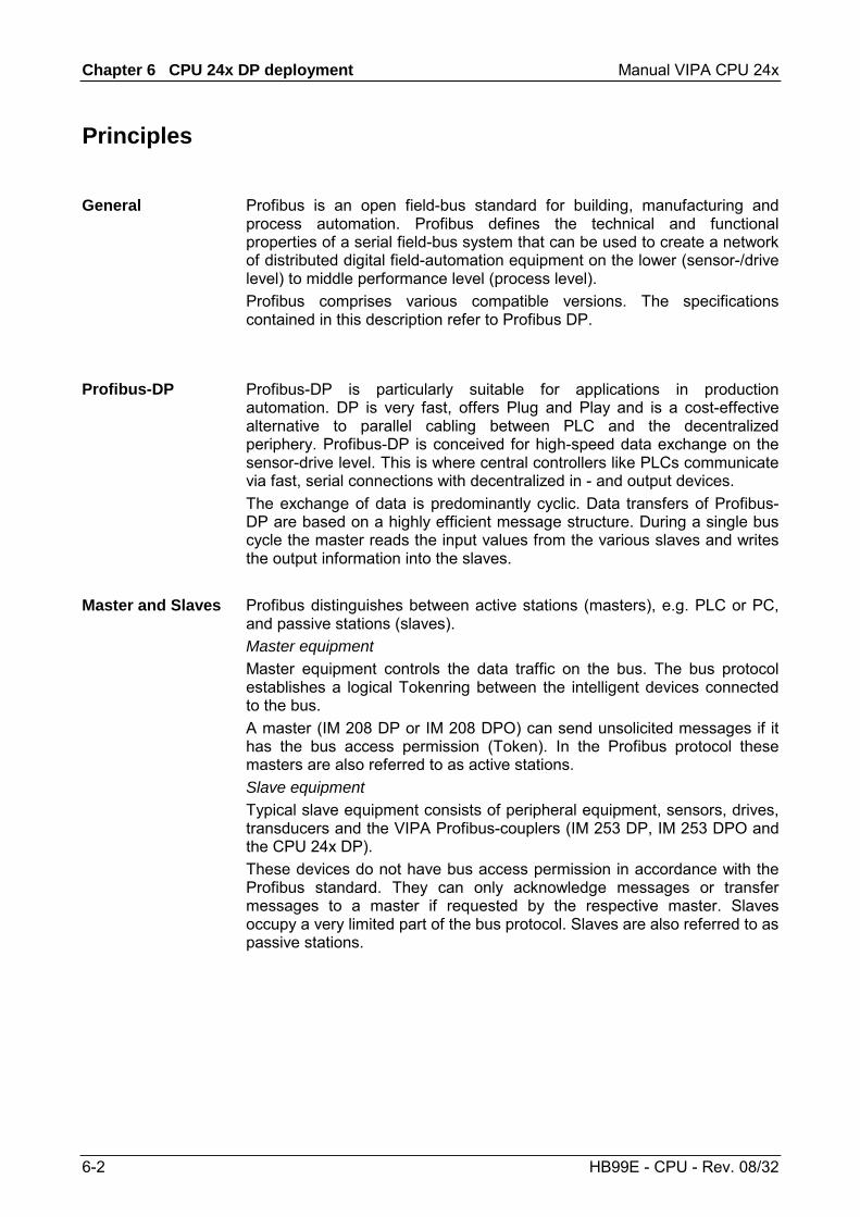
Chapter 6 CPU 24x DP deployment Manual VIPA CPU 24x
6-2 HB99E - CPU - Rev. 08/32
Principles
Profibus is an open field-bus standard for building, manufacturing and process automation. Profibus defines the technical and functional properties of a serial field-bus system that can be used to create a network of distributed digital field-automation equipment on the lower (sensor-/drive level) to middle performance level (process level). Profibus comprises various compatible versions. The specifications contained in this description refer to Profibus DP.
Profibus-DP is particularly suitable for applications in production automation. DP is very fast, offers Plug and Play and is a cost-effective alternative to parallel cabling between PLC and the decentralized periphery. Profibus-DP is conceived for high-speed data exchange on the sensor-drive level. This is where central controllers like PLCs communicate via fast, serial connections with decentralized in - and output devices. The exchange of data is predominantly cyclic. Data transfers of Profibus-DP are based on a highly efficient message structure. During a single bus cycle the master reads the input values from the various slaves and writes the output information into the slaves. Profibus distinguishes between active stations (masters), e.g. PLC or PC, and passive stations (slaves). Master equipment Master equipment controls the data traffic on the bus. The bus protocol establishes a logical Tokenring between the intelligent devices connected to the bus. A master (IM 208 DP or IM 208 DPO) can send unsolicited messages if it has the bus access permission (Token). In the Profibus protocol these masters are also referred to as active stations. Slave equipment Typical slave equipment consists of peripheral equipment, sensors, drives, transducers and the VIPA Profibus-couplers (IM 253 DP, IM 253 DPO and the CPU 24x DP). These devices do not have bus access permission in accordance with the Profibus standard. They can only acknowledge messages or transfer messages to a master if requested by the respective master. Slaves occupy a very limited part of the bus protocol. Slaves are also referred to as passive stations.
General
Profibus-DP
Master and Slaves
Manual VIPA CPU 24x Chapter 6 CPU 24x DP deployment
HB99E - CPU - Rev. 08/32 6-3
The bus communication protocol provides two procedures for accessing the bus: Communications with the master is also referred to as token passing. Token passing guarantees that the station receives access permission to the bus. This access right to the bus is passed between the stations in form of a "token". A token is a specific message that is transferred via the bus. When a master is in the possession of the token it also has the access right to the bus and can communicate with all other active and passive stations. The token retention time is defined at the time when the system is being configured. When the token retention time has expired the token is passed along to the next master that acquires the bus access rights with the token so that it can communicate with all other stations.
Data is exchanged in a fixed repetitive sequence between the master and the slaves assigned to the respective master. When you configure the system you define which slaves are assigned to a certain master. You can also specify which DP-slave is included in the cyclic exchange of application data and which ones are excluded. The master-slave data transfer is divided into configuration, configuration and data transfer phases. Before a DP-slave is included in the data transfer phase the master verifies whether the specified configuration agrees with the actual configuration in the configuration phase. This verification process checks the device type, the format and length as well as the number of inputs and outputs. This provides you with effective protection against configuration errors. The master handles application data transfers independently. In addition you can also send new configuration data to a bus coupler. You can use these two access methods to implement systems based on a single or multiple masters. In this way you achieve a high degree of flexibility for the system configuration.
Communication
Master to Master
Master-Slave procedure

Chapter 6 CPU 24x DP deployment Manual VIPA CPU 24x
6-4 HB99E - CPU - Rev. 08/32
The data exchange between the DP-master and the CPU 24x DP is performed in a cycle using send- and receive buffers.
DP-Master (z.B. IM208)
Input Output
Peripheal area
CPU 24x DP
Controlprocessor
Communicationprocessor
Application program
PAPE
Transmit buffer
Receive buffer
PLC cycleDP cycle
PE: Peripheral area for inputsPA: Peripheral area for outputs
Profibus DP additional interfaces
Data is transferred in two cycles: in the AG-cycle and in the DP-cycle.
The application program writes the transmit data into the peripheral area of the CPU outputs (PA). At the checkpoints defined in the cycle the communication processor copies the transmit data from the PA into its DP-transmit buffer. At the same time the communication processor copies the received data into the peripheral area of the inputs (PE). The application program can analyze received data saved in the PE. The exchange of data between the control and the communication processor takes place at the cycle checkpoint.
The principle of data transfer operations
AG cycle
Manual VIPA CPU 24x Chapter 6 CPU 24x DP deployment
HB99E - CPU - Rev. 08/32 6-5
The DP-master transmits data to the CPU 24x DP that is saved in the receive buffer of the communication processor. Simultaneously, the transmit data of the CPU 24x DP is collected by the DP-master. The DP-master to DP-slave data exchange on the bus is repeated cyclically and does not depend on the cycle checkpoint of the CPU 24x DP.
Data is referred to a being consistent if has the same logical contents. Data that belongs together is: the high - and low-byte of an analog value (word consistency) and the control and the status byte with the respective parameter word required to access the registers. The data consistency during the interaction between the peripherals and the controller is only guaranteed for 1 byte. That is, the bits of one byte are acquired together and they are transmitted together. Byte-wise consistency is sufficient for the processing of digital signals. Where the length of the data exceeds a single byte, e.g. analog-values the data consistency must be expanded. Profibus guarantees consistency for the required length of data. Please ensure that you use the correct method to read consistent data from the Profibus master into your PLC. For additional information please refer to the manual on your Profibus master as well as the one for the interface module.
When a high-level master fails this is not recognized automatically by the CPU. You should always pass along a control byte to indicate the presence of the master thereby identifying valid master data. The example at the end of this chapter also explains the use of the control byte.
DP cycle
Data consistency
Restriction
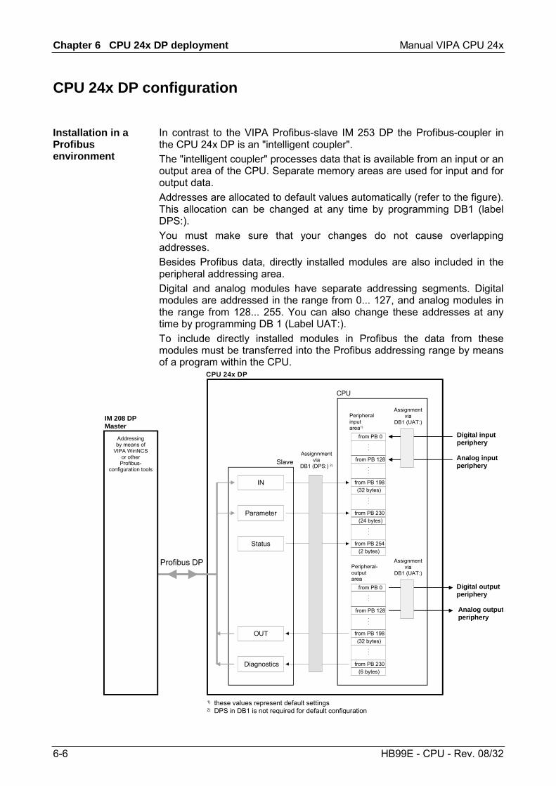
Chapter 6 CPU 24x DP deployment Manual VIPA CPU 24x
6-6 HB99E - CPU - Rev. 08/32
CPU 24x DP configuration
In contrast to the VIPA Profibus-slave IM 253 DP the Profibus-coupler in the CPU 24x DP is an "intelligent coupler". The "intelligent coupler" processes data that is available from an input or an output area of the CPU. Separate memory areas are used for input and for output data. Addresses are allocated to default values automatically (refer to the figure). This allocation can be changed at any time by programming DB1 (label DPS:). You must make sure that your changes do not cause overlapping addresses. Besides Profibus data, directly installed modules are also included in the peripheral addressing area. Digital and analog modules have separate addressing segments. Digital modules are addressed in the range from 0... 127, and analog modules in the range from 128... 255. You can also change these addresses at any time by programming DB 1 (Label UAT:). To include directly installed modules in Profibus the data from these modules must be transferred into the Profibus addressing range by means of a program within the CPU.
CPU
Slave
Profibus DP
IN
OUT
Parameter
Diagnostics
Status
Assignnmentvia
DB1 (DPS:) 2)
CPU 24x DP
1) these values represent default settings2) DPS in DB1 is not required for default configuration
from PB 198
from PB 230
...
(32 bytes)
(24 bytes)
from PB 254
...
(2 bytes)
from PB 0...
from PB 128...
Peripheralinputarea1)
Assignmentvia
DB1 (UAT:)
from PB 198
from PB 230
...
(32 bytes)
(6 bytes)
from PB 0...
from PB 128...
Peripheral-outputarea
Digital outputperiphery
Analog outputperiphery
Digital inputperiphery
Analog inputperiphery
Assignmentvia
DB1 (UAT:)
IM 208 DPMaster
Addressingby means of
VIPA WinNCSor other
Profibus-configuration tools
Installation in a Profibus environment
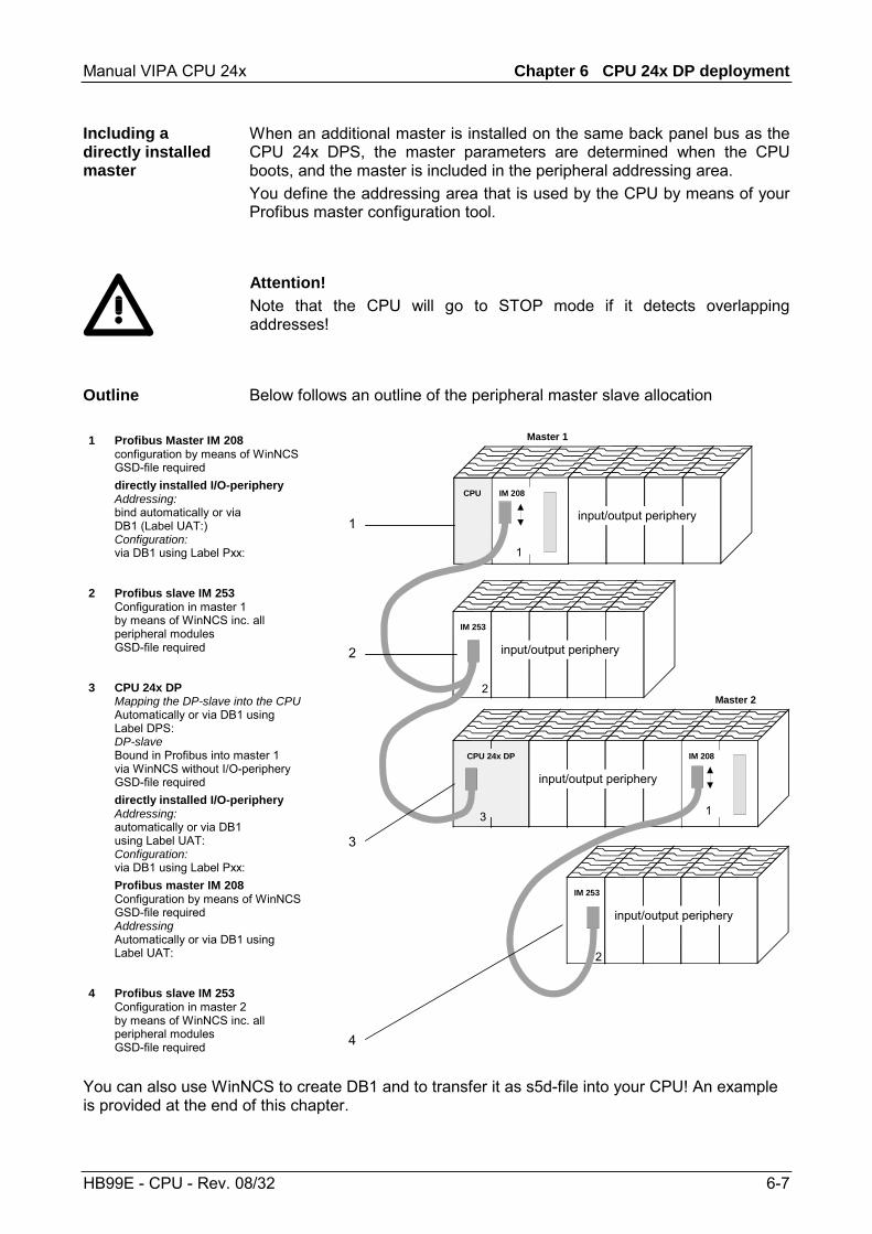
Manual VIPA CPU 24x Chapter 6 CPU 24x DP deployment
HB99E - CPU - Rev. 08/32 6-7
When an additional master is installed on the same back panel bus as the CPU 24x DPS, the master parameters are determined when the CPU boots, and the master is included in the peripheral addressing area. You define the addressing area that is used by the CPU by means of your Profibus master configuration tool.
Attention! Note that the CPU will go to STOP mode if it detects overlapping addresses!
Below follows an outline of the peripheral master slave allocation
3
CPU IM 208
1
IM 253
2
input/output periphery
input/output periphery
IM 253
2
input/output periphery
IM 208
1
input/output periphery
Master 1
Master 2
CPU 24x DP
1
2
3
4 You can also use WinNCS to create DB1 and to transfer it as s5d-file into your CPU! An example is provided at the end of this chapter.
Including a directly installed master
Outline
1 Profibus Master IM 208 configuration by means of WinNCS GSD-file required directly installed I/O-periphery Addressing: bind automatically or via DB1 (Label UAT:) Configuration: via DB1 using Label Pxx:
2 Profibus slave IM 253 Configuration in master 1 by means of WinNCS inc. all peripheral modules GSD-file required
3 CPU 24x DP Mapping the DP-slave into the CPU Automatically or via DB1 using Label DPS: DP-slave Bound in Profibus into master 1 via WinNCS without I/O-periphery GSD-file required directly installed I/O-periphery Addressing: automatically or via DB1 using Label UAT: Configuration: via DB1 using Label Pxx: Profibus master IM 208 Configuration by means of WinNCS GSD-file required Addressing Automatically or via DB1 using Label UAT:
4 Profibus slave IM 253 Configuration in master 2 by means of WinNCS inc. all peripheral modules GSD-file required
Chapter 6 CPU 24x DP deployment Manual VIPA CPU 24x
6-8 HB99E - CPU - Rev. 08/32
The GSD-file included in the package is required when the CPU 24x DP must be bound to a master system on a higher level.
The IM 208 DP and IM 208 DP that are available from VIPA and that Siemens IM 308-C are suitable master interfaces for the PLC. For the configuration of a slave interface the GSD-file is included. This contains the performance specifications of the VIPA CPU 24 x DP. The standard determines the structure, contents and encoding of the GSD-file. The GSD-file provides the details required for the configuration of any DP-slave by means of the configuration devices that are available from different manufacturers. This data is archived by the Profibus user organization (PNO) for without regard for the respective manufacturer and can be accessed at any time. The name of the GSD-file for the VIPA CPU 24x DP: VIPA04D5.GSD You must install this GSD-file into your configuration tool. For details on the installation of the GSD-file refer to the manual provided with your configuration tool. The GSD-file also contains the Ident-number specifying the bus equipment. Ident-numbers are also managed by the PNO and for VIPA bus-equipment these are: Ident-number VIPA CPU 24x DP: 04D5h
WinNCS is the VIPA configuration tool for VIPA Profibus master modules. WinNCS is normally supplied with the latest revision of the GSD-file. However, you can always link other GSD-files with WinNCS. For this purpose you change to the WinNCS directory that was created during the installation and copy your GSD-file into this directory. The new GSD-file will be used when you restart WinNCS.
Configuration in a master located on a higher level
GSD-file
Linking the GSD-file to WinNCS

Manual VIPA CPU 24x Chapter 6 CPU 24x DP deployment
HB99E - CPU - Rev. 08/32 6-9
Modifying the default addressing by means of DB 1
During the boot procedure of the CPU the modules installed on the back-panel bus of are scanned and addresses are assigned to them in the peripheral-area of the CPU. At this stage the CPU 24x DP assigns memory areas to the input and output data of the integrated Profibus-coupler. These assignments take place automatically by means of default addresses or manually by means of DB1 programming. The modules connected to the Profibus can be accessed by means of read and write functions. Using WinNCS you can also create the required DB 1. A detailed example of such a procedure is provided at the end of this chapter. The following addresses have been reserved for use by the Profibus slave in the CPU:
Data type Data width Peripheral area (default) Input data IN 64 bytes max. 32 bytes from PW 198 Output data OUT 64 bytes max. 32 bytes from PW 198 Parameters IN 24 bytes 24 bytes from PW 230 Diagnostic data OUT 6 bytes 6 bytes from PW 230 Status data IN 2 bytes 2 bytes from PW 254
You can use the label DPS (DP slave) to assign new data-areas to the integrated Profibus-coupler. This label is always accompanied by 7byte parameters that are separated by a space and that follow the "DPS:" label. These bytes have the following contents:
Byte Function Range 0 Start address input data 0 ... 255 1 Data width input data 0 ... 64 2 Start address output data 0 ... 255 3 Data size output data 0 ... 64 4 Start address parameter data 0 ... 232*) 5 Start address diagnostic data 0 ... 250*) 6 Start address status data 0 ... 254*)
*) If these data fields are set to 255 they are ignored, i.e. the respective memory locations are not used for this data.
Note! The 7byte parameters must always be specified when the DPS label is used!
Addressing ranges for Profibus slave
Label DPS
Chapter 6 CPU 24x DP deployment Manual VIPA CPU 24x
6-10 HB99E - CPU - Rev. 08/32
Example The following example shows the use of the DPS label in DB 1. The following entries must be defined by means of the DB 1: - input data from address 100 with a width of 16 bytes - output data from address 0 with a width of 64 bytes - no parameter data - diagnostic data from address 230 (fixed width of 6 bytes) - status data from address 240 (fixed width of 2 bytes) The resulting data for DB 1 is as follows: DB1
KC= DPS: 100 16 0 64 255 230 240 ;
Note! Every label, every number and every semicolon must be separated with a space! (see the example at the end of the chapter) The following starting areas have been reserved in the CPU for directly installed I/O modules: Module type Peripheral area digital input module from PB0 in the input area analog input module from PB128 in the input area digital output module from PB0 in the output area analog output module from PB128 in the output area
You can assign new data areas to the installed I/O modules by means of the UAT (User Address Table) label by entering the peripheral address in accordance with the sequence in which the modules have been installed. The following must be observed when programming the DB 1: • Every address consists of 2bytes and the high-byte must always be 0. • Where combined modules are concerned it is necessary to first
configure the input address and then the output address. • You can set the address of analog modules to 0. This places the module
into the process image, which means that they are updated with every cycle. Please remember that this would extend the cycle time.
• Entries are in string-format (KC-format).
Addressing areas for directly installed I/O modules
Label UAT
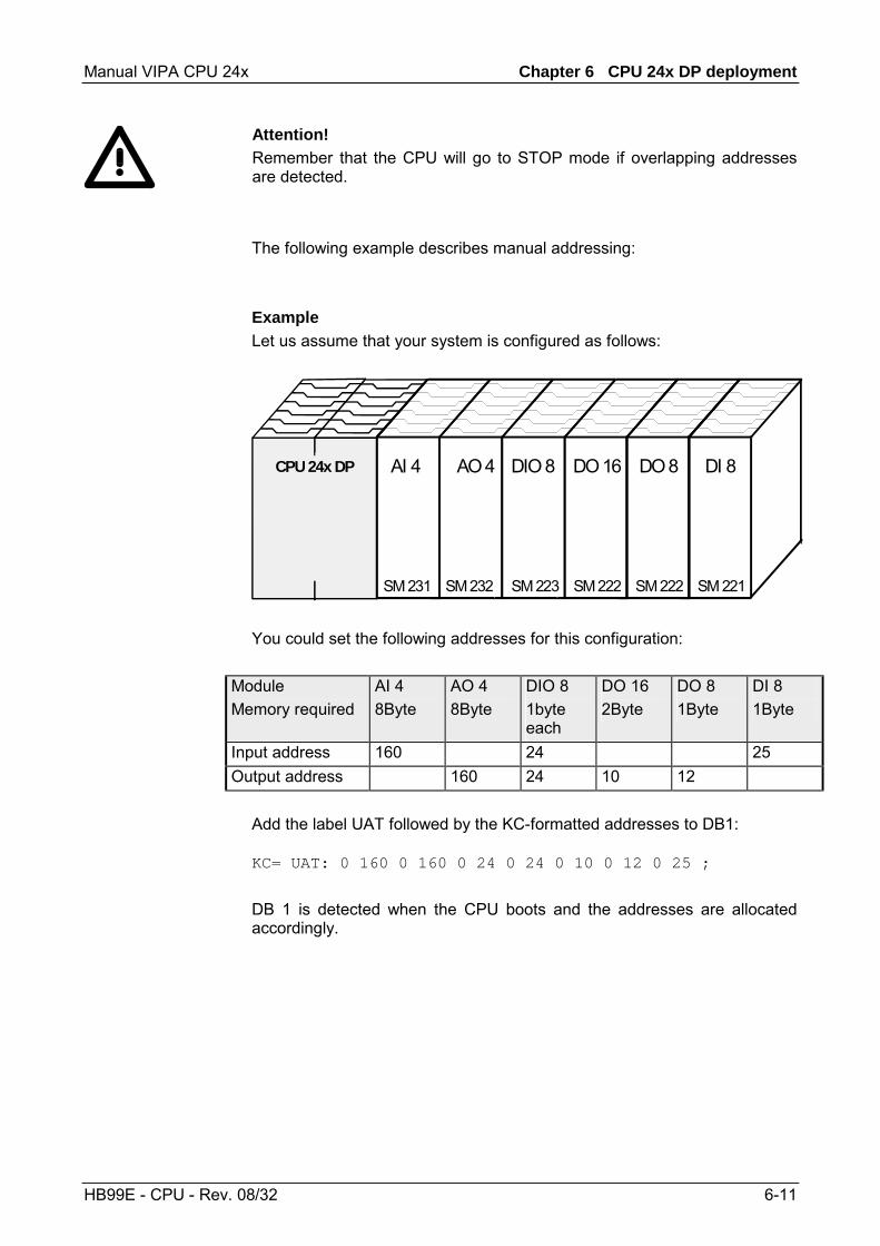
Manual VIPA CPU 24x Chapter 6 CPU 24x DP deployment
HB99E - CPU - Rev. 08/32 6-11
Attention! Remember that the CPU will go to STOP mode if overlapping addresses are detected.
The following example describes manual addressing: Example Let us assume that your system is configured as follows:
2
CPU 24x DP AI 4 AO 4 DIO 8 DO 16
SM 222SM 231 SM 232 SM 223
DO 8
SM 222
DI 8
SM 221 You could set the following addresses for this configuration:
Module Memory required
AI 4 8Byte
AO 4 8Byte
DIO 8 1byte each
DO 16 2Byte
DO 8 1Byte
DI 8 1Byte
Input address 160 24 25 Output address 160 24 10 12
Add the label UAT followed by the KC-formatted addresses to DB1:
KC= UAT: 0 160 0 160 0 24 0 24 0 10 0 12 0 25 ;
DB 1 is detected when the CPU boots and the addresses are allocated accordingly.

Chapter 6 CPU 24x DP deployment Manual VIPA CPU 24x
6-12 HB99E - CPU - Rev. 08/32
Access to parameter data
Parameter data contains the configuration for a Profibus slave. This data is generated at the time when the master is being configured. Parameter data consists of Profibus specific data (bus parameters) and user specific data. On the CPU 24x DP this contains the definition of the input and output bytes. The user specific data (byte 7 ... 9) is mapped into the process image.
The master issues new parameter data when • the CPU 24x DP is in booting • the connection between the CPU 24x DP and the master failed, for
instance by a short removal of the bus connector.
The parameter data message consists of 32bytes which have the following structure: Byte Identifier Description 0 ... 6 Standard Profibus parameter
data The standard parameters can not be displayed.
The next 24bytes are mapped into the process image. 7 ... 9 Spec_User_Prm_Byte This area is reserved for
future expansion. These always contain 0.
10 ... 31 User_Prm_Data This contains the configuration bytes of the input/output periphery that you have configured b y means of WinNCS.
Updates
Structure

Manual VIPA CPU 24x Chapter 6 CPU 24x DP deployment
HB99E - CPU - Rev. 08/32 6-13
Configuration of directly installed I/O modules
Directly installed modules like analog modules can receive up to 16bytes of configuration data from the CPU. In DB 1 you can specify a specific hex-formatted configuration for every plug-in location. A label is allocated to each plug-in location: Plug-in location (1...32) → Label (P01...P32) The following example explains the configuration procedure by means of two analog modules:
Example The system is configured as follows:
AI 4x16Bit Multi-input- No diagnostic alarm- Channel 0: voltage input (-10 ... +10V)- Channel 1: current input (4 ... 20mA)- Channel 2: Pt100 (-200 ... 850°C)- Channel 3: no input- Default options
AO 4x12Bit Multioutput- No diagnostic alarm- Channel 0: current output (4 ... 20mA)- Channel 1: current output (1 ... 5V)- Kanal 2: no output
2
CPU 24x DP AI 4 AO 4
SM 231 SM 232
This results in the following configuration for the analog modules:
Diagnostic alarm byte
reserved
Function no. channel 0
Function no. channel 1
Function no. channel 2
Function no. channel 3
Option byte channel 0
Option byte channel 1
Option byte channel 2
Option byte channel 3
AI 4x16Bit Multi-input
Byte 0
Byte 1
Byte 2
Byte 3
Byte 4
Byte 5
Byte 6
Byte 7
Byte 8
Byte 9
00h
00h
2Bh
2Dh
02h
00h
00h
00h
00h
00h
Parameter areas :
Diagnostic alarm byte
reserved
Function byte channel 0
Function byte channel 1
Function byte channel 2
Function byte channel 3
AO 4x12Bit Multi-output
Byte 0
Byte 1
Byte 2
Byte 3
Byte 4
Byte 5
00h
00h
04h
02h
00h
01h
Add the KC-formatted (string) Pxx (xx for the plug-in location) to DB1 followed by the hex parameter. Use semicolons to separate the different entries: KC= P01: 00 00 2B 2D 02 00 00 00 00 00 ;
P02: 00 00 04 02 00 01 ;
Every label, every number and every semicolon must be separated by a space!
Chapter 6 CPU 24x DP deployment Manual VIPA CPU 24x
6-14 HB99E - CPU - Rev. 08/32
Diagnostic functions of the CPU 24x DP
Profibus-DP an extensive set of diagnostic functions that can be used to locate problems quickly and effectively. Diagnostic messages are transferred via the bus and collected by the master. The CPU 24x DP transmits diagnostic data when requested by the master or when an error occurs. Since a portion of the diagnostic data (byte 11 ... 15) is located in the peripheral address range of the CPU you can start the diagnostics and modify the diagnostic data. Diagnostic data consists of: • standard diagnostic data (byte 0 ... 5), • equipment related diagnostic data (byte 6 ... 15).
The structure of the diagnostic data is as follows:
Standard diagnostic data Byte 0 Station status 1 Byte 1 Station status 2 Byte 2 Station status 3 Byte 3 Master address Byte 4 Ident number (low) Byte 5 Ident number (high)
Equipment related diagnostic data
Byte 6 Length and code of equipment related diagnostics
Byte 7 Equipment related diagnostic messages
Byte 8 ... Byte 10 reserved Byte 11 ... Byte 15 User-specific diagnostic data
is mapped into the peripheral addressing range of the CPU and can be modified.
Byte 11 contains the diagnostic status byte, which you can use to start a diagnostic routine. Further details are available from the notes accompanying the equipment-related diagnostics described on the following pages.
Outline
Structure
Starting diagnostics

Manual VIPA CPU 24x Chapter 6 CPU 24x DP deployment
HB99E - CPU - Rev. 08/32 6-15
Details on the structure of the standard diagnostic data are available from the literature on the Profibus standards. This documentation is available from the Profibus User Organization.
7 0 bit-no.
Diagnostic station does not exist (set by master)
Diag.station_not_readySlave not ready for data exchange
Diag.cfg_faultConfiguration data do not match
Diag.ext_diagSlave has external diagnostic data
Diag.not_supportedSlave does not support the requested function
Diag.invalid_slave_response(sets slave to 0 permanently)
Diag.prm_faultbad parameters (Ident-No. etc.)
Diag.master_lock (set by master)Slave was configured by other master
Byte 0
Byte 3 Diag.master_addMaster address ater configurationFFh without configuration
7 0 bit-no.
Diag.prm_reqSlave requires new configuration
Diag.stat_diagstatistical diagnostics
permanently at 1
Diag.wd_onWatchdog active
Diag.freeze_modeFreeze command was received
Sync_modeSync command was received
reserved
Diag.deactivated (set by master)
Byte 1
7 0 bit-no.
reserved
Diag.ext_overflow
Byte 2
Byte 4 Identnumber high byte
Byte 5 Identnumber low byte
Standard diagnostic data
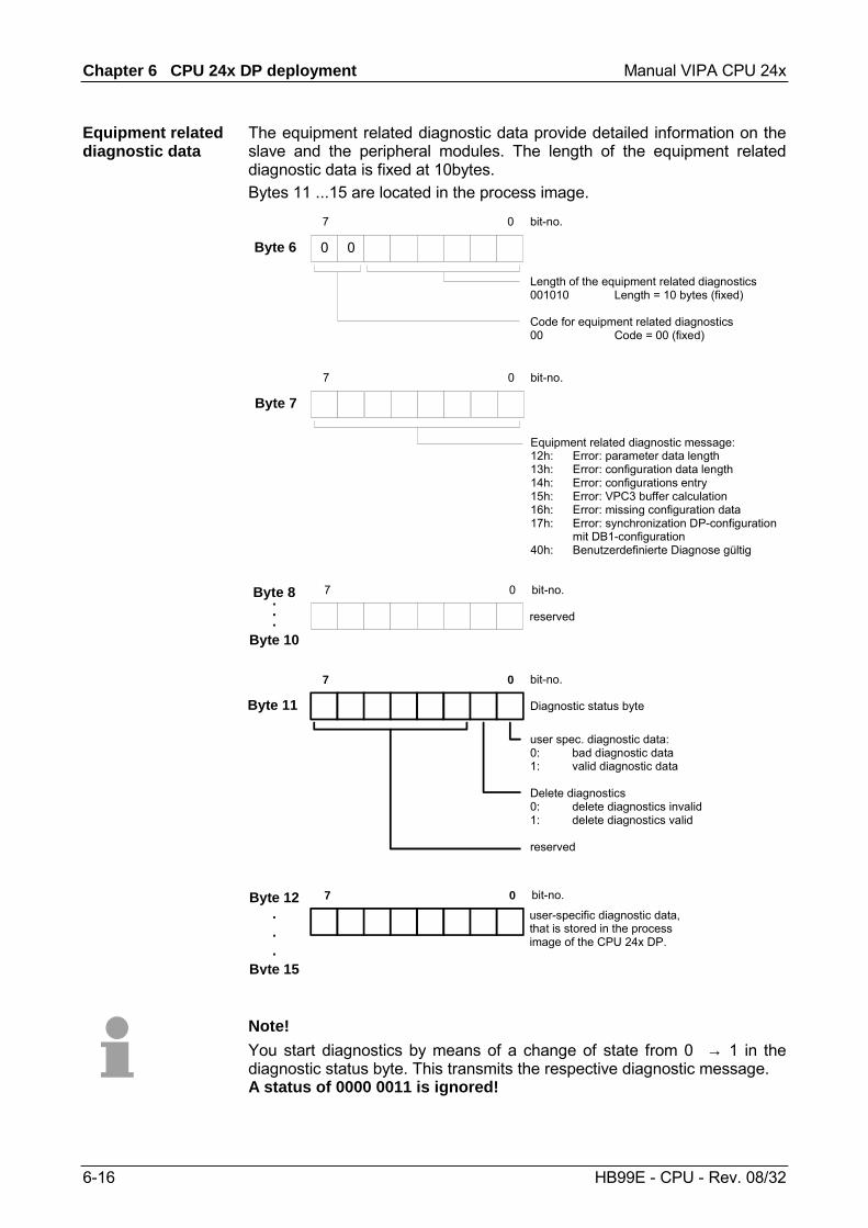
Chapter 6 CPU 24x DP deployment Manual VIPA CPU 24x
6-16 HB99E - CPU - Rev. 08/32
The equipment related diagnostic data provide detailed information on the slave and the peripheral modules. The length of the equipment related diagnostic data is fixed at 10bytes. Bytes 11 ...15 are located in the process image.
7 0 bit-no.
Length of the equipment related diagnostics001010 Length = 10 bytes (fixed)
Code for equipment related diagnostics00 Code = 00 (fixed)
Byte 6 0 0
Byte 8...
Byte 10reserved
7 0 bit-no.
7 0 bit-no.
Byte 7
Equipment related diagnostic message:12h: Error: parameter data length13h: Error: configuration data length14h: Error: configurations entry15h: Error: VPC3 buffer calculation16h: Error: missing configuration data17h: Error: synchronization DP-configuration mit DB1-configuration40h: Benutzerdefinierte Diagnose gültig
Byte 12...
Byte 15
user-specific diagnostic data,that is stored in the processimage of the CPU 24x DP.
7 0 bit-no.
7 0 bit-no.
user spec. diagnostic data:0: bad diagnostic data1: valid diagnostic data
Delete diagnostics0: delete diagnostics invalid1: delete diagnostics valid
reserved
Byte 11 Diagnostic status byte
Note! You start diagnostics by means of a change of state from 0 → 1 in the diagnostic status byte. This transmits the respective diagnostic message. A status of 0000 0011 is ignored!
Equipment related diagnostic data
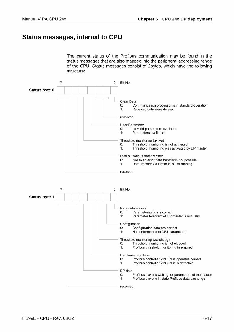
Manual VIPA CPU 24x Chapter 6 CPU 24x DP deployment
HB99E - CPU - Rev. 08/32 6-17
Status messages, internal to CPU
The current status of the Profibus communication may be found in the status messages that are also mapped into the peripheral addressing range of the CPU. Status messages consist of 2bytes, which have the following structure:
7 0 Bit-No.
Status byte 0
Clear Data0: Communication processor is in standard operation1: Received data were deleted
reserved
User Parameter0: no valid parameters available1: Parameters available
Threshold monitoring (aktive)0: Threshold monitoring is not activated1: Threshold monitoring was activated by DP master
Status Profibus data transfer0: due to an error data transfer is not possible1 Data transfer via Profibus is just running
reserved
7 0 Bit-No.
Status byte 1
Parameterization0: Parameterization is correct1: Parameter telegram of DP master is not valid
Configuration0: Configuration data are correct1: No conformance to DB1 parameters
Threshold monitoring (watchdog)0: Threshold monitoring is not elapsed1: Profibus threshold monitoring in elapsed
Hardware monitoring0: Profibus controller VPC3plus operates correct1 Profibus controller VPC3plus is defective
DP data0: Profibus slave is waiting for parameters of the master1 Profibus slave is in state Profibus data exchange
reserved
Chapter 6 CPU 24x DP deployment Manual VIPA CPU 24x
6-18 HB99E - CPU - Rev. 08/32
The transmit and receive buffers are cleared when an error occurs.
These bits are reserved for future use.
Indicates validity of the parameter data. Parameter data is entered into the master configuration tool.
Indicates the status of the activation of the response monitor in the Profibus-master. The slave will terminate communications when the response monitoring time is exceeded.
Status indicator for master communications. A bad configuration or bad parameters will terminate communications and the error respective error is indicated by means of this bit.
Displays the status of the configuration data. The length of the configuration data and the number of configuration bytes is analyzed. The configuration is only accepted as being correct if these equal and if no more than 31 bytes of parameter data is transferred.
Status indicator of the configuration data that was received from the Profibus master. You define the configuration by means of the master configuration tool.
Indicates the status of the response monitor in the Profibus master. This location contains an error when the response monitor has been activated and the required response time has been exceeded in the Slave.
This bit is set if the Profibus-controller VPC3plus in the CPU 24x DP is defective. In this case you should contact the VIPA Hotline.
Any transfer error on the Profibus will set this error.
Parameter
Clear Data
reserved
User Parameter
Response monitoring (active)
Profibus data exchange status
Configuration
Configuration
Response monitoring (Watchdog)
Hardware monitoring
DP data
Manual VIPA CPU 24x Chapter 6 CPU 24x DP deployment
HB99E - CPU - Rev. 08/32 6-19
Installation guidelines
• The VIPA Profibus-DP-network must have a linear structure. • Profibus DP consists of at least one segment with a minimum of one
master and one slave. • A master must always be used in conjunction with a CPU. • Profibus supports a max. of 125 stations. • A max. of 32 stations are permitted per segment. • The maximum length of a segment depends on the data transfer rate:
9.6 ... 187.5kBaud → 1000m 500kBaud → 400m 1.5MBaud → 200m 3 ... 12MBaud → 100m
• A maximum of 10 segments can be established. Segments are connected by means of repeaters. Every repeater is regarded as a station.
• All the stations communicate at the same Baud-rate. Slaves adapt automatically to the Baud-rate.
• Only on optical master is permitted per line. • Multiple masters can be used in conjunction with a single CPU as long
as they are installed on the same back panel bus (do not exceed the max. current consumption).
• The maximum distance of an FO-link between two slaves communicating at 12MBaud is 50m.
• The bus does not require termination.
Note! At the end of the bus you should place a cover over the socket for the next station to avoid eye damage and to eliminate the chance of disturbance by external radiation. Use the rubber inserts for this purpose y inserting them into the two remaining openings of the FO-connector. • the bus must be terminated at both ends. • Masters and slaves can be installed in any sequence.
• An FO-master can only be connected to an electrical system directly by means of an Optical Link Plug, i.e. slaves are not permitted between a master and the OLP.
• A maximum of one adapter (OLP) may be installed between two masters.
Profibus in general
optical System
electrical system
Composite system
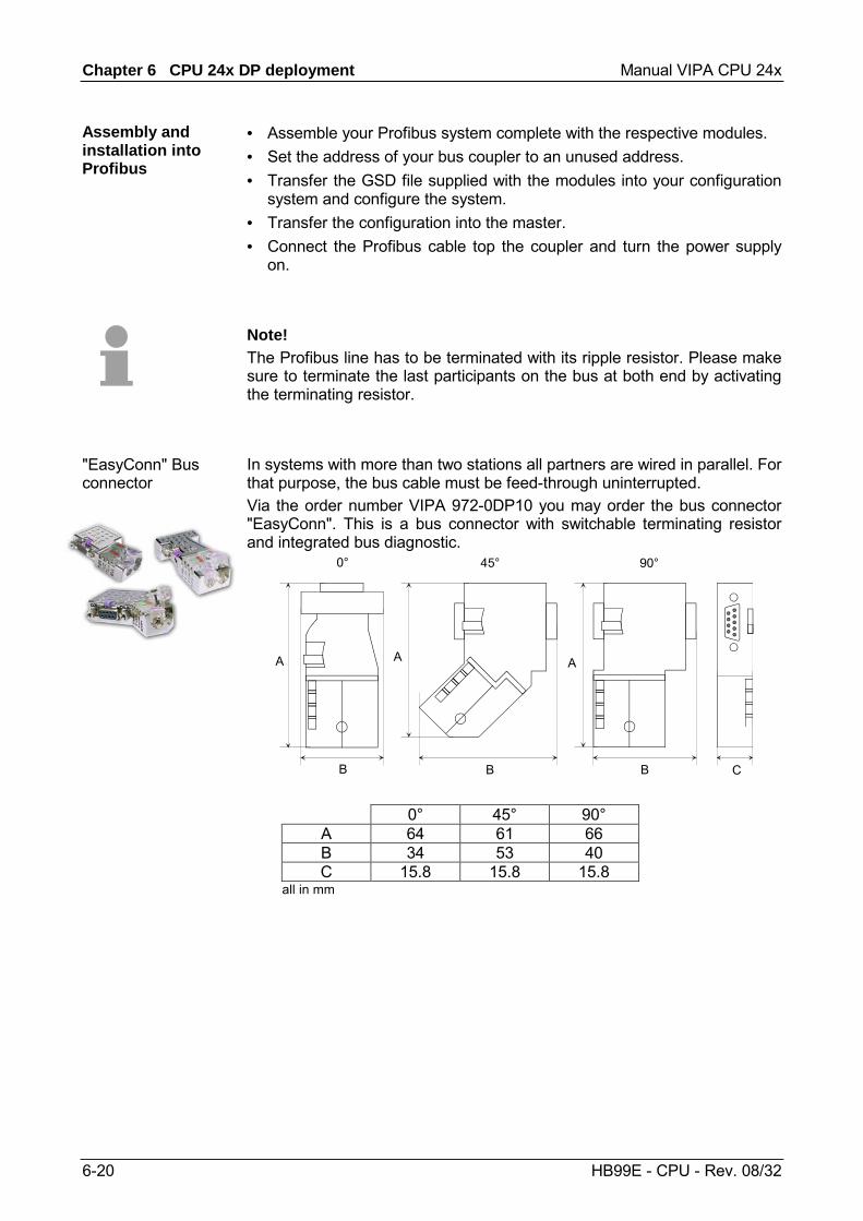
Chapter 6 CPU 24x DP deployment Manual VIPA CPU 24x
6-20 HB99E - CPU - Rev. 08/32
• Assemble your Profibus system complete with the respective modules. • Set the address of your bus coupler to an unused address. • Transfer the GSD file supplied with the modules into your configuration
system and configure the system. • Transfer the configuration into the master. • Connect the Profibus cable top the coupler and turn the power supply
on.
Note! The Profibus line has to be terminated with its ripple resistor. Please make sure to terminate the last participants on the bus at both end by activating the terminating resistor.
In systems with more than two stations all partners are wired in parallel. For that purpose, the bus cable must be feed-through uninterrupted. Via the order number VIPA 972-0DP10 you may order the bus connector "EasyConn". This is a bus connector with switchable terminating resistor and integrated bus diagnostic.
C
A
B
90°
A
B
0°
B
A
45°
0° 45° 90° A 64 61 66 B 34 53 40 C 15.8 15.8 15.8
all in mm
Assembly and installation into Profibus
"EasyConn" Bus connector
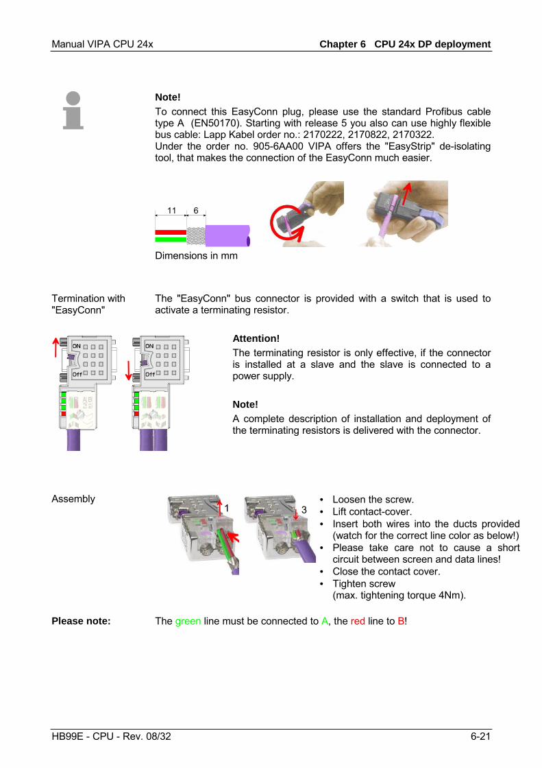
Manual VIPA CPU 24x Chapter 6 CPU 24x DP deployment
HB99E - CPU - Rev. 08/32 6-21
Note! To connect this EasyConn plug, please use the standard Profibus cable type A (EN50170). Starting with release 5 you also can use highly flexible bus cable: Lapp Kabel order no.: 2170222, 2170822, 2170322. Under the order no. 905-6AA00 VIPA offers the "EasyStrip" de-isolating tool, that makes the connection of the EasyConn much easier.
11 6
Dimensions in mm The "EasyConn" bus connector is provided with a switch that is used to activate a terminating resistor.
Attention! The terminating resistor is only effective, if the connector is installed at a slave and the slave is connected to a power supply. Note! A complete description of installation and deployment of the terminating resistors is delivered with the connector.
• Loosen the screw. • Lift contact-cover. • Insert both wires into the ducts provided
(watch for the correct line color as below!)• Please take care not to cause a short
circuit between screen and data lines! • Close the contact cover. • Tighten screw
(max. tightening torque 4Nm). The green line must be connected to A, the red line to B!
Termination with "EasyConn"
Assembly
Please note:
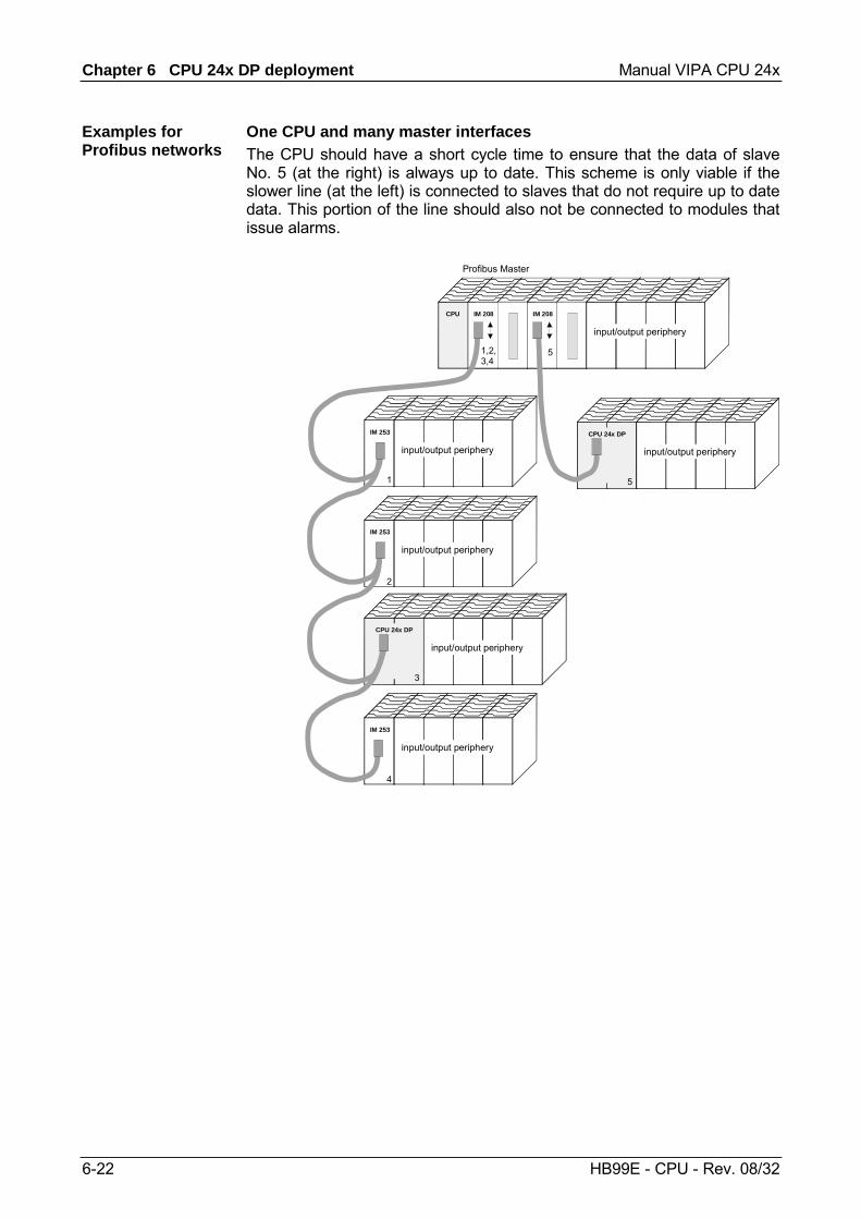
Chapter 6 CPU 24x DP deployment Manual VIPA CPU 24x
6-22 HB99E - CPU - Rev. 08/32
One CPU and many master interfaces The CPU should have a short cycle time to ensure that the data of slave No. 5 (at the right) is always up to date. This scheme is only viable if the slower line (at the left) is connected to slaves that do not require up to date data. This portion of the line should also not be connected to modules that issue alarms.
3
input/output periphery
CPU 24x DP
IM 253
1
input/output periphery
IM 253
2
input/output periphery
IM 253
4
input/output periphery
5
input/output periphery
CPU IM 208
1,2,3,4
IM 208
5
CPU 24x DP
Profibus Master
input/output periphery
Examples for Profibus networks
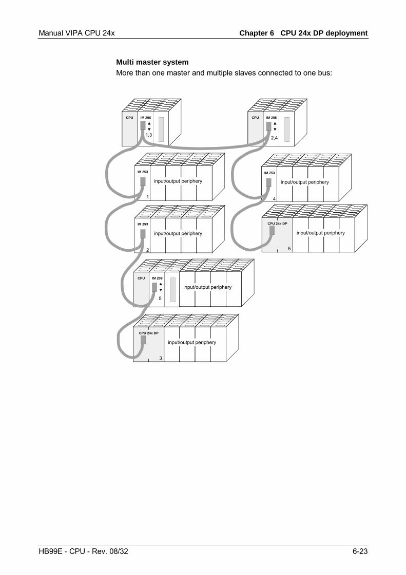
Manual VIPA CPU 24x Chapter 6 CPU 24x DP deployment
HB99E - CPU - Rev. 08/32 6-23
Multi master system More than one master and multiple slaves connected to one bus:
3
input/output periphery
CPU 24x DP
5
input/output periphery
CPU 24x DP
CPU IM 208
5
CPU IM 208
1,3
IM 253
1
input/output periphery
IM 253
2
input/output periphery
CPU IM 208
2,4
IM 253
4
input/output periphery
input/output periphery
Chapter 6 CPU 24x DP deployment Manual VIPA CPU 24x
6-24 HB99E - CPU - Rev. 08/32
Commissioning
• Install the CPU 24x DP. • Configure the CPU 24x DP in your master system. • Configure the I/O periphery that is connected to the back panel bus. • Connect the CPU 24x DP to your Profibus. • Turn the power supply on.
Assemble the CPU 24x DP with the required peripheral modules. Do not exceed the maximum current capacity of your power supply.
Configure your CPU 24x DP in your master system. You can use the VIPA WinNCS package for this purpose.
Note! I/O modules that are connected directly by means of the back panel bus cannot be configured in the master! The master only has facilities to process 64bytes of I/O-data that is mapped into the peripheral addressing range of the CPU 24x DP.
The system 200V peripheral modules connected directly to the CPU 24x DP by means of the back panel bus are automatically mapped into the addressing range of the CPU. You can change the address allocation at any time by programming DB 1. You can also refer to "Changing the default addressing by means of DB 1" In systems having more than two stations all the stations are wired in parallel. For this purpose the bus cable must be connected in a continuous uninterrupted loop.
Note! The bus cable must always be terminated with its characteristic impedance to prevent reflections, which could cause communication problems!
Outline
Installation
Configuration in the master system
Configuration of the connected I/O periphery

Manual VIPA CPU 24x Chapter 6 CPU 24x DP deployment
HB99E - CPU - Rev. 08/32 6-25
Profibus employs a screened twisted two-wire cable that as the communication medium, which is based on the RS485 interface. The RS485 interface employs differential voltages. For this reason less sensitive to electrical interference than a voltage or a current base interface. You can configure networks with linear as well as a star-type geometry. Your VIPA CPU 24x DP carries a 9-pin socket. You connect the Profibus coupler directly to your Profibus network as a slave by means of this connector. Every segment supports a maximum of 32 stations. Different segments are connected by means of repeaters. That maximum length of a segment depends on the data communication rate. The rate of data transfer of a Profibus-DP link set to a value in the range between 9.6 kBaud and 12 MBaud. Slaves are configured automatically. All the stations on the network communicate at the same baud rate. The structure of the bus is such that stations can be inserted or removed without repercussions or to commission the system in different stages. Extensions to the network do not influence those stations that have already been commissioned. New stations or stations that have failed are detected automatically.
L2P
shield
Master interface Slave interface
3
8
L2P3
8
shield
L2N L2N
Attention! The bus cable must always be terminated with its characteristic impedance to prevent reflections, which could cause communication problems!
Profibus connections
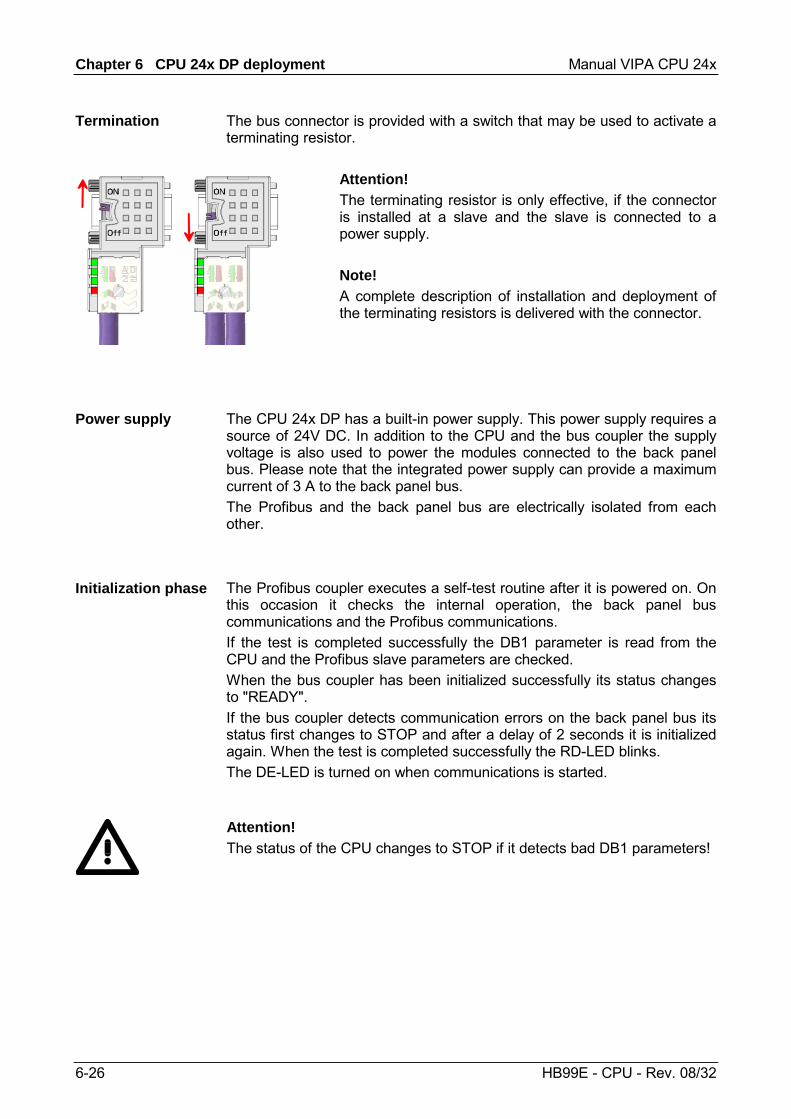
Chapter 6 CPU 24x DP deployment Manual VIPA CPU 24x
6-26 HB99E - CPU - Rev. 08/32
The bus connector is provided with a switch that may be used to activate a terminating resistor.
Attention! The terminating resistor is only effective, if the connector is installed at a slave and the slave is connected to a power supply. Note! A complete description of installation and deployment of the terminating resistors is delivered with the connector.
The CPU 24x DP has a built-in power supply. This power supply requires a source of 24V DC. In addition to the CPU and the bus coupler the supply voltage is also used to power the modules connected to the back panel bus. Please note that the integrated power supply can provide a maximum current of 3 A to the back panel bus. The Profibus and the back panel bus are electrically isolated from each other.
The Profibus coupler executes a self-test routine after it is powered on. On this occasion it checks the internal operation, the back panel bus communications and the Profibus communications. If the test is completed successfully the DB1 parameter is read from the CPU and the Profibus slave parameters are checked. When the bus coupler has been initialized successfully its status changes to "READY". If the bus coupler detects communication errors on the back panel bus its status first changes to STOP and after a delay of 2 seconds it is initialized again. When the test is completed successfully the RD-LED blinks. The DE-LED is turned on when communications is started.
Attention! The status of the CPU changes to STOP if it detects bad DB1 parameters!
Termination
Power supply
Initialization phase
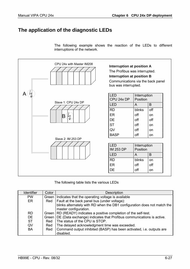
Manual VIPA CPU 24x Chapter 6 CPU 24x DP deployment
HB99E - CPU - Rev. 08/32 6-27
The application of the diagnostic LEDs
The following example shows the reaction of the LEDs to different interruptions of the network.
A
B
Slave 1: CPU 24x DP
Slave 2: IM 253 DP
CPU 24x with Master IM208
The following table lists the various LEDs
Identifier Color Description PW Green Indicates that the operating voltage is available ER Red Fault at the back panel bus (under voltage):
blinks alternately with RD when the DB1 configuration does not match the master configuration.
RD Green RD (READY) indicates a positive completion of the self-test. DE Green DE (Data exchange) indicates that Profibus communications is active. ST Red The status of the CPU is STOP. QV Red The delayed acknowledgment time was exceeded. BA Red Command output inhibited (BASP) has been activated, i.e. outputs are
disabled.
LED CPU 24x DP
Interruption Position
LED A B RD blinks off ER off on DE off off ST off on QV off on BASP off on
LED IM 253 DP
Interruption Position
LED A B RD blinks on ER off off DE off on
Interruption at position A The Profibus was interrupted. Interruption at position B Communications via the back panel bus was interrupted.
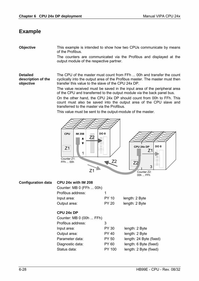
Chapter 6 CPU 24x DP deployment Manual VIPA CPU 24x
6-28 HB99E - CPU - Rev. 08/32
Example
This example is intended to show how two CPUs communicate by means of the Profibus. The counters are communicated via the Profibus and displayed at the output module of the respective partner.
The CPU of the master must count from FFh ... 00h and transfer the count cyclically into the output area of the Profibus master. The master must then transfer this value to the slave of the CPU 24x DP. The value received must be saved in the input area of the peripheral area of the CPU and transferred to the output module via the back panel bus. On the other hand, the CPU 24x DP should count from 00h to FFh. This count must also be saved into the output area of the CPU slave and transferred to the master via the Profibus. This value must be sent to the output-module of the master.
CPU IM 208
1
DO 8
3
CPU 24x DP DO 8
Z1
Z2
Z1
Z2
Z2
Z1
Counter Z1:FFh ... 00h
Counter Z2:00h ... FFh
CPU 24x with IM 208 Counter: MB 0 (FFh ... 00h) Profibus address: 1 Input area: PY 10 length: 2 Byte Output area: PY 20 length: 2 Byte
CPU 24x DP Counter: MB 0 (00h ... FFh) Profibus address: 3 Input area: PY 30 length: 2 Byte Output area: PY 40 length: 2 Byte Parameter data: PY 50 length: 24 Byte (fixed) Diagnostic data: PY 60 length: 6 Byte (fixed) Status data: PY 100 length: 2 Byte (fixed)
Objective
Detailed description of the objective
Configuration data
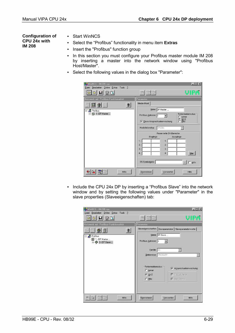
Manual VIPA CPU 24x Chapter 6 CPU 24x DP deployment
HB99E - CPU - Rev. 08/32 6-29
• Start WinNCS • Select the “Profibus” functionality in menu item Extras • Insert the "Profibus" function group • In this section you must configure your Profibus master module IM 208
by inserting a master into the network window using "Profibus Host/Master".
• Select the following values in the dialog box "Parameter":
• Include the CPU 24x DP by inserting a “Profibus Slave” into the network
window and by setting the following values under "Parameter" in the slave properties (Slaveeigenschaften) tab:
Configuration of CPU 24x with IM 208
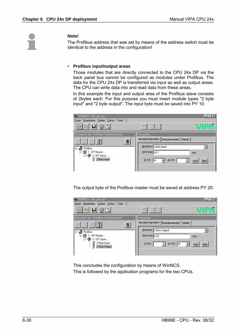
Chapter 6 CPU 24x DP deployment Manual VIPA CPU 24x
6-30 HB99E - CPU - Rev. 08/32
Note! The Profibus address that was set by means of the address switch must be identical to the address in the configuration! • Profibus input/output areas
Those modules that are directly connected to the CPU 24x DP via the back panel bus cannot be configured as modules under Profibus. The data for the CPU 24x DP is transferred via input as well as output areas. The CPU can write data into and read data from these areas. In this example the input and output area of the Profibus slave consists of 2bytes each. For this purpose you must insert module types "2 byte input" and "2 byte output". The input byte must be saved into PY 10:
The output byte of the Profibus master must be saved at address PY 20:
This concludes the configuration by means of WinNCS. This is followed by the application programs for the two CPUs.
Manual VIPA CPU 24x Chapter 6 CPU 24x DP deployment
HB99E - CPU - Rev. 08/32 6-31
The application program in the CPU 24x has two tasks that are handled by two OBs: • to test communications by means of the control byte.
Load the input byte from Profibus and transfer the value to the output module.
OB 1 (cyclic call)
:L KH 00FF :T AB 20 Control byte for Slave-CPU : :L KH 00FE Load control value 0xFE :L EB 10 Was the control byte transferred :><F correctly from the slave CPU? :BEB No -> End : : ------------------------------- : Data exchange via Profibus : :L EB 11 Load input byte 11 (output data : of the CPU24xDP) and :T AB 0 transfer to output byte 0 : :BE
• Read counter level from MB 0, decrement, save in MB 0 and output to
CPU 24x DP via Profibus. OB 13 (timer-OB)
:L MB 0 Counter from 0xFF to 0x00 :L KH 0001 :-F :T MB 0 : :T AB 21 Transfer into output byte 21 : (input data of CPU24xDP) :BE
At this point the program of the CPU 24x and the IM 208 DP is complete. The Profibus communication has also been defined for both sides. It is only necessary to specify the application program for the CPU 24x DP.
Application program in the CPU 24x

Chapter 6 CPU 24x DP deployment Manual VIPA CPU 24x
6-32 HB99E - CPU - Rev. 08/32
As shown above, the application program in the CPU 24x has two tasks that are handled by two OBs: • Load the input byte from Profibus and transfer the value to the output
module. OB 1 (cyclic call)
:L PW 100 Load status data and save in :T MW 100 flag word : :UN M 100.5 Was the installation finalized :BEB by the DP-master? No -> End : :U M 101.4 Valid receive data? :BEB No -> End :L KH 00FF Load control value and compare :L PY 30 to control byte :><F (1st input byte) :BEB Received data does not contain : valid values : :L KH 00FE Control byte for master-CPU :T PY 40 ------------------------------- : Data exchange via Profibus : :L PY 31 Load peripheral byte 31 (input : data from Profibus slave) and :T AB 0 transfer into output byte 0 : :BE
• Read counter level from MB 0, increment, save into MB 0 and output to
CPU 24x via Profibus.
OB 13 (timer-OB) :L MB 0 Counter from 0x00 to 0xFF :L KH 0001 :+F :T MB 0 : :T PY 41 Transfer counter value into : peripheral byte 41 (output data : of the Profibus slave) :BE
Application program in the CPU 24x DP
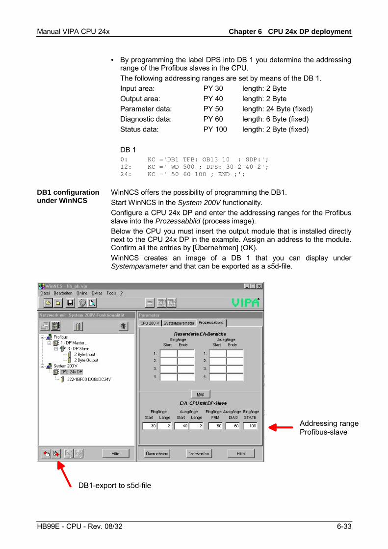
Manual VIPA CPU 24x Chapter 6 CPU 24x DP deployment
HB99E - CPU - Rev. 08/32 6-33
• By programming the label DPS into DB 1 you determine the addressing range of the Profibus slaves in the CPU. The following addressing ranges are set by means of the DB 1. Input area: PY 30 length: 2 Byte Output area: PY 40 length: 2 Byte Parameter data: PY 50 length: 24 Byte (fixed) Diagnostic data: PY 60 length: 6 Byte (fixed) Status data: PY 100 length: 2 Byte (fixed) DB 1 0: KC ='DB1 TFB: OB13 10 ; SDP:'; 12: KC =' WD 500 ; DPS: 30 2 40 2'; 24: KC =' 50 60 100 ; END ;';
WinNCS offers the possibility of programming the DB1. Start WinNCS in the System 200V functionality. Configure a CPU 24x DP and enter the addressing ranges for the Profibus slave into the Prozessabbild (process image). Below the CPU you must insert the output module that is installed directly next to the CPU 24x DP in the example. Assign an address to the module. Confirm all the entries by [Übernehmen] (OK). WinNCS creates an image of a DB 1 that you can display under Systemparameter and that can be exported as a s5d-file.
DB1-export to s5d-file
Addressing rangeProfibus-slave
DB1 configuration under WinNCS

Chapter 6 CPU 24x DP deployment Manual VIPA CPU 24x
6-34 HB99E - CPU - Rev. 08/32
Manual VIPA CPU 24x Chapter 7 Operating modes
HB99E - CPU - Rev. 08/32 7-1
Chapter 7 Operating modes
This chapter describes the operating modes STOP, START-UP and RUN. It contains information on the different bootstrap methods related organization blocks where you can enter your specific program for the different booting methods. You are also provided with information about the program execution methods "Cyclic processing", " Timer controlled processing" and "Alarm controlled processing" and which components are available for your application program.
Topic Page Chapter 7 Operating modes............................................................. 7-1
Introduction and outline ........................................................................ 7-2 Program processing levels ................................................................... 7-3 Operating mode STOP......................................................................... 7-6 Operating mode START-UP................................................................. 7-8 Operating mode RUN......................................................................... 7-11 Program flow...................................................................................... 7-12
Outline
Contents

Chapter 7 Operating modes Manual VIPA CPU 24x
7-2 HB99E - CPU - Rev. 08/32
Introduction and outline
The CPU 24x has three operating modes: • Operating mode STOP • Operating mode START-UP • Operating mode RUN In operating modes START-UP and RUN certain events can occur that should cause a reaction from the system program. In many instances this issues a call to an organization block (from OB 1 to OB 31) that is subsequently used as the user interface. Operating modes are displayed by means of LEDs located on the front plate of the CPU. You must manually activate some operating modes. You can use the control elements on the front panel of the CPU for this purpose.
Operating modes Various LEDs on the front plate of the CPU are used to display the current operating mode of the CPU. The following table shows the relationship between the STOP- and RUN-LED indicators and the respective operating mode. These indicators are supported by a number of additional LED indicators (BASP, QVZ, ZYK). The following table shows the significance of the "RUN" and "STOP" LEDs:
Operating modes RUN STOP Operating mode on off The operating mode of the CPU is RUN off on The operating mode of the CPU is STOP on on The operating mode of the CPU is START-UP or
the CPU is in START-UP/RUN mode and the processing check was active when a break point was encountered, or the CPU is in START-UP/RUN mode and the processing check was active when a break point was removed before it was executed (wait-state)
The most important internal functions are monitored continuously. When the status of the internal functions varies from the standard a system error is issued. You can obtain information on the cause of the system error from the system data-word.
Operating modes
LED indicators for operating modes and errors
System error

Manual VIPA CPU 24x Chapter 7 Operating modes
HB99E - CPU - Rev. 08/32 7-3
Program processing levels
Here follows an overview of the operating modes and processing levels of the CPU 24x.
Operating mode:STOP
RUN-LED OffSTOP-LED OnBASP-LED On
Operating mode:ANLAUF
RUN-LED OnSTOP-LED OnBASP-LED On
STPPEUBAU
DOPPSTUEUSTUEB
Manualreboot/
Power on
BCFLZF
QVZSSF
Operating mode:RUN
RUN-LED OnSTOP-LED OffBASP-LED Off
CycleTimer jobPromptControl alarmDelay alarm
Process alarm
WECK-FEREG-FEZYKBCFLZF
QVZSSF
STPPEUBAU
DOPPSTUEUSTUEB
Power off
NAU
NAU
NAUPower off Function switch,PG-STP
Explanation of the abbreviations: STP = stop statement PEU = periphery out of order BAU = battery out of order, battery discharged or not installed DOPP = double error (an active error processing routine is activated again - reboot required) STUEU = USTACK - overflow STUEB = BSTACK - overflow NAU = = power failure PG-STP = Stop selected at the PG
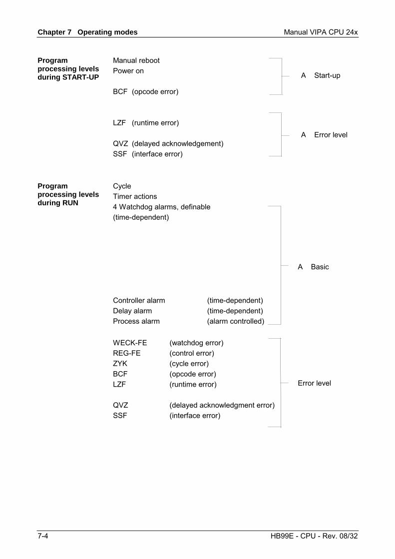
Chapter 7 Operating modes Manual VIPA CPU 24x
7-4 HB99E - CPU - Rev. 08/32
Manual reboot Power on BCF (opcode error) LZF (runtime error) QVZ (delayed acknowledgement) SSF (interface error)
Cycle Timer actions 4 Watchdog alarms, definable (time-dependent) Controller alarm (time-dependent) Delay alarm (time-dependent) Process alarm (alarm controlled)
WECK-FE (watchdog error) REG-FE (control error) ZYK (cycle error) BCF (opcode error) LZF (runtime error) QVZ (delayed acknowledgment error) SSF (interface error)
Program processing levels during START-UP
Program processing levels during RUN
A Start-up l l
A Error level
Error level
A Basic l l
Manual VIPA CPU 24x Chapter 7 Operating modes
HB99E - CPU - Rev. 08/32 7-5
A program processing level is characterized by certain features that have been summarized below. Nesting of other levels When an event requires processing on a higher priority then the current level is interrupted by the system program and the level with the higher priority is inserted. Specific system program A separate system program is associated with every program processing level. USTACK When an OB has been called the PLC-instructions are executed. The current register set is saved in USTACK and a new register set is generated. A register set consists of: ACCU 1 ...2, block stack pointer, block address register, data block start-address/length, STEP address counter and base address register. Priority The different program processing levels have a defined priority. Depending on the priority these can interrupt each other and they can be nested with one another. The basic levels can only be nested at block boundaries. Start-up and error levels are inserted at the next instruction boundary when the respective event has occurred. When errors occur the most recent one always has the highest priority. Reaction to a double error An error level that has been activated that has not yet been processed completely cannot be activated again. In this case the CPU immediately goes to STOP mode. An exception to this are the watchdog errors. The DOPP signal and the accessed error level are ticked in the USTACK with a depth "01".
Characteristics of a program processing level
Chapter 7 Operating modes Manual VIPA CPU 24x
7-6 HB99E - CPU - Rev. 08/32
Operating mode STOP
Operating mode STOP is characterized by the following: Application program The application program is not being processed. Data retention If a program was being processed the values of counters, times, flags and of the process image are retained during the change into the STOP mode. BASP signal Outputs are disabled, i.e. all digital outputs are inhibited. USTACK If a program was being processed then you can obtain an information block specifying the cause for the interrupt from the USTACK.
RUN-LED off BASP-LED on STOP-LED on The operating mode STOP was triggered by: • RUN/STOP switch set to STOP • PG function AG-STOP • PG function "Processing check End" • Equipment error (BAU, PEU) • Overall reset (IPL)
Identifier
LED indicators
Manual VIPA CPU 24x Chapter 7 Operating modes
HB99E - CPU - Rev. 08/32 7-7
The factory settings are restored to the CPU by an overall reset. The program, data, registers and pointers are erased and if an EPROM or a Flash-ROM card is installed the data is transferred into the CPU. The overall reset must be requested before it can be executed. When the CPU is used with an EPROM it is possible to reset and restart the CPU.
An overall reset can be requested by the system or by the user. Request issued by the system program An initialization routine is executed with every power on and after an overall reset. If this should cause an error then the CPU goes to STOP mode. The reason for the error must always be removed. Please contact the VIPA Hotline if this is not possible. Request issued by the user The following sequence of operations requests an overall reset: Place the RUN/STOP-switch in position STOP (STOP-LED on permanently). • Hold the operating mode push button in position "OR" and move the
operating mode switch from "ST" to "RN". • Repeat this procedure a number of times. The red LED “ST” is
extinguished briefly. → The CPU has been reset and the red LED "ST" is on permanently. You can also reset the CPU from the PG. For this purpose you must use the PG-function OVERALL RESET (URLÖSCHEN). In this case the manual reset request can be omitted. The position of the operating mode switch is irrelevant.
Note! After an overall reset the only valid start-up method is REBOOT (NEUSTART).
Overall reset
Overall reset
Chapter 7 Operating modes Manual VIPA CPU 24x
7-8 HB99E - CPU - Rev. 08/32
Operating mode START-UP
The following properties characterize the operating mode Start-Up: Organization blocks (OBs) No limit applies to the length of the organization. In addition the time required for the procedure is not monitored. It is possible to call other blocks from the start-up OBs. The following organization blocks are called: Reboot OB 21 Automatic warm restart OB 22 Data manipulation The values of counters, timers, markers and process images are treated in different ways by the different start-up methods. BASP signal During start-up al the digital outputs are disabled, i.e. the outputs are inhibited. LEDs on the front plate RUN-LED on STOP-LED on BASP-LED on Start-up methods The following basic types of start-up exist for the in operating mode start-up. These are subdivided again: • Reboot • Warm restart
Identifier

Manual VIPA CPU 24x Chapter 7 Operating modes
HB99E - CPU - Rev. 08/32 7-9
All flags, timers, counters and the process image are cleared if "non-remanent" was selected. The processing of the application program starts from the beginning. A warm restart is always permitted, provided that the system program does not request a reboot. Reboot with manual reset (manual warm restart) Place the RUN/STOP switch in position RUN. As a result the CPU executes a manual warm restart and indicates the RUN mode by means of the RUN-LED.
The status of the flags, timers and counters is retained during the inactive period. A warm restart is not permitted when an overall reset has been requested or if one of the following events has occurred: • double call to a program processing level, • overall reset (control bits: URGELOE), • start-up interrupted (control bits: ANL-ABB), • STOP after PG function PROCESSING CHECK END
(BEARBEITUNGSKONTROLLE ENDE), • Compress in STOP mode, • Stack overflow, • Changes to the application program in STOP mode. Automatic warm restart When power returns the unit will automatically go to the operating mode RUN. Conditions for an automatic warm restart: • RUN/STOP switch remains in position RUN, • CPU was in RUN mode when the power was removed, • no errors occurred during the initialization phase.
Reboot
Warm restart
Chapter 7 Operating modes Manual VIPA CPU 24x
7-10 HB99E - CPU - Rev. 08/32
The organization blocks OB 21 and OB 22 serve as user interface for the different start-up methods. You can save your program for the different start-up methods in these blocks. For instance, you can set flags, start timers, prepare the data exchange between the CPU and the periphery and execute the synchronization of several CPUs with the periphery. The OBs have the following functions: OB 21 - Reboot When the CPU executes a manual reboot the system program issues a single call to the OB 21 . You should store a program in OB 21 that prepares the CPU for restarting cyclic processing. When OB 21 has been processed cyclic processing of the program is started by a call to OB 1. OB 22 - Automatic warm restart During a warm restart the system program issues a call to OB 22 . You must store a program in OB 22 that controls the restart of a program that was previously in RUN mode. After OB 22 the cyclic processing of the program is initiated. In this case the same conditions apply as for the manual restart: • The BASP signal remains active during the processing of the remaining
cycle and it is only deactivated when a new cycle is started. • The process image remains reset at the end of the remaining cycle.
A start-up program can be interrupted by: • a power failure at the central unit or in the extension unit, • STOP (switch, command), • program and equipment error.
User interface for start-up
Interruptions during start-up

Manual VIPA CPU 24x Chapter 7 Operating modes
HB99E - CPU - Rev. 08/32 7-11
Operating mode RUN
When the CPU has completed the processing of a start-up it changes to operating mode RUN. Here follow characteristics of this condition: Processing of the application program The application program in OB 1 is processed on a cyclic basis. At this time other routines of the program can be inserted under control of alarms. Timers, counters, process image All timers and counters that were started in the program are active and the process image is updated on a cyclic basis. BASP-signal The BASP-signal (outputs disable) is deactivated, i.e. all digital outputs are enabled. LEDs on the front plate RUN-LED on STOP-LED off BASP-LED off
The program processing levels are initiated by various events. The user interface for every processing level is provided by a separate set of OBs and FBs. Programming for all the basic program processing levels can be simultaneously present in the CPU 24x. The system program issues calls to the respective level depending on the priority. The CPU offers the following basic program processing levels in operating mode RUN: • Cycle
The application program is processed ion a cyclic basis. • Timed execution Your application program is processed at definable intervals. You can also
specify a fixed time at which the application program should be executed.
• 1 watchdog alarm The application program is processed at fixed intervals as presented by the system.
• Process alarm The processing of the application program under control of alarms.
Characteristics
Program processing levels
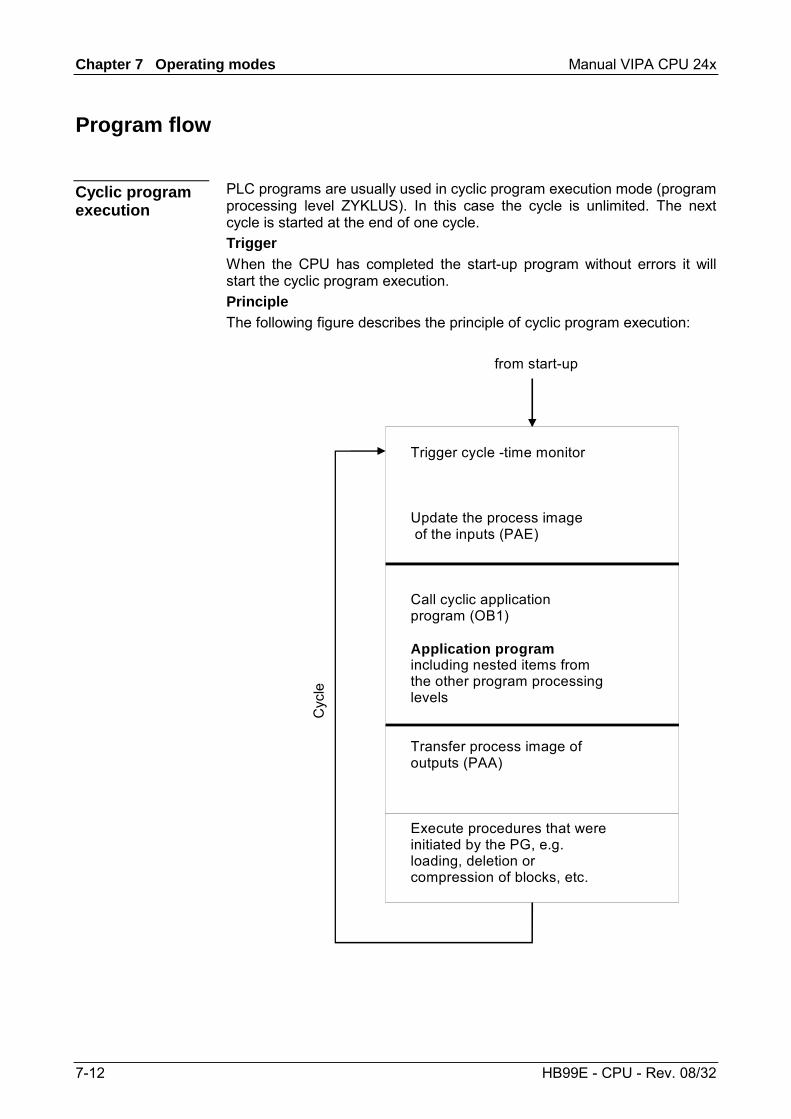
Chapter 7 Operating modes Manual VIPA CPU 24x
7-12 HB99E - CPU - Rev. 08/32
Program flow
PLC programs are usually used in cyclic program execution mode (program processing level ZYKLUS). In this case the cycle is unlimited. The next cycle is started at the end of one cycle. Trigger When the CPU has completed the start-up program without errors it will start the cyclic program execution. Principle The following figure describes the principle of cyclic program execution:
Trigger cycle -time monitor
Update the process image of the inputs (PAE)
Call cyclic applicationprogram (OB1)
Application programincluding nested items from the other program processinglevels
Transfer process image ofoutputs (PAA)
Execute procedures that wereinitiated by the PG, e.g.loading, deletion or compression of blocks, etc.
from start-up
Cyc
le
Cyclic program execution
Manual VIPA CPU 24x Chapter 7 Operating modes
HB99E - CPU - Rev. 08/32 7-13
User interface OB1 During cyclic program execution OB 1 is called at regular intervals as the user interface. The application program in OB 1 is processed completely from the start and including the calls to blocks that you have programmed. Interrupt locations Cyclic program execution can be interrupted at the boundaries of the block by means of: • process alarm controlled program processing, • controller processing, • time-dependent program processing. Cyclic program execution can be interrupted or terminated at the instruction boundaries: • when an equipment fault or a program error occurs, • operation (PG-function, STOP-switch), • STOP-instruction.
ACCUs as storage medium for data In the CPU 24x you can use the arithmetic registers ACCU 1 to 2 as data memory that retains its information over the end of the cycle (end of program cycle to the start of the next one).
Chapter 7 Operating modes Manual VIPA CPU 24x
7-14 HB99E - CPU - Rev. 08/32
In the CPU 24x-series alarm-controlled program processing is provided by the OB 2. A module of the system 200V can initiate an interrupt in the CPU via the bus-line. The consequence of this interrupt is that the OB 2 is called at the next command boundary. The alarm-block can interrupt an active time-dependent routine. A timer-controlled program, i.e. OB 6 cannot be interrupted. Additional alarms that occur during the processing will be discarded. To properly assign the alarm that has occurred only one alarm-enabled module may exist in the system.
The time controlled program execution is accepted by OB 6. The execution of the time controlled program processing is coordinated by system date BS 101. If a value is transferred into the system date the time is started until the call is issued to OB 6. The number of BS cells defines the time in ms. The BS cell is cleared when OB 6 is called. The accumulated time is retriggerable, i.e. if a new value is transferred into the BS-cell then the time re-started with the respective value. The call as well as the timer can be stopped by writing a value of zero into the BS-cell. Time-controlled program processing can not be interrupted by time-dependent nor by alarm controlled program processing.
Alarm controlled program processing
Time controlled program processing

Manual VIPA CPU 24x Chapter 7 Operating modes
HB99E - CPU - Rev. 08/32 7-15
During time dependent program processing the CPU is triggered by an internal clock or by a time-related signal to interrupt the current cycle of program processing and to start a specific program. When the called program has been completed the CPU returns to the point where it was interrupted. In this way you can insert time-dependent program segments into the program. Watchdog alarms Issues alarms at definable time intervals from 10ms ... 5s using a watchdog alarm. OBs are assigned to the watchdog alarms (OB 10 ... OB13). These consist of fixed cycles, i.e. the duration between two program starts is fixed.
Attention! During timer or alarm controlled processing the danger exists that flags are overwritten. You can save the flags at the start of an alarm or time dependent routine and retrieve them at a later stage, or you can use S-flags of which a sufficient number are available.
The time is defined in system data BS 97 to BS 100 or in DB 1.
OB System data Priority 13 BS 97 highest 12 BS 98 11 BS 99 10 BS 100 lowest
Time dependent program processing can be interrupted by an alarm (OB 2) or by time-controlled program processing (OB 6).
Time dependent program processing
Chapter 7 Operating modes Manual VIPA CPU 24x
7-16 HB99E - CPU - Rev. 08/32
Time controlled and alarm controlled program processing is always assigned a higher priority over time-dependent program processing. When time-controlled program-processing (OB 6) and alarm-controlled processing (OB 2) are active at the same time the time-controlled program so (OB 6) is usually processed first. These priorities can be reversed by setting system bit BS 120.6 or by the respective setting in DB 1.
A triggering error is set when processing is initiated again while a time controlled or a time-dependent program is being processed. The triggering error is also issued if processing is requested again while an alarm is inhibited. A trigger causes a call to OB 33. An error code specifying the triggering error is entered into accumulator 1:
Error code Reason 1 processing of OB 6 2 processing of OB 13 3 processing of OB 12 4 processing of OB 11 5 processing of OB 10
Note! Detailed explanations on the processing of alarms are contained in chapter "Alarm and time dependent processing".
Priorising
Triggering error

Manual VIPA CPU 24x Chapter 8 Introduction to the programming language
HB99E - CPU - Rev. 08/32 8-1
Chapter 8 Introduction to the programming language
This chapter describes the programming of automation tasks. It explains how you can create programs and which blocks can be used to structure a program. The chapter also contains a summary of the different numeric representations that are available in the programming language.
Topic Page Chapter 8 Introduction to the programming language .................. 8-1
Programming procedure....................................................................... 8-2 Creating a program .............................................................................. 8-4 Program structure................................................................................. 8-8 Block types........................................................................................... 8-9 Program execution ............................................................................. 8-22 Processing of blocks .......................................................................... 8-32 Numeric representation ...................................................................... 8-34 Troubleshooting the program.............................................................. 8-35
Outline
Contents
Chapter 8 Introduction to the programming language Manual VIPA CPU 24x
8-2 HB99E - CPU - Rev. 08/32
Programming procedure
A control program can be divided into three sections: - Technical concept, - Program design, - Programming, testing and implementation.
• Prepare a rough block diagram of the control units required in your process.
• Collect a list of the input and output signals required by the process. • Refine the block diagram by assigning the signals and any possible
timing conditions or counters to the different blocks.
• Conceptualize the processing modes (cyclic or timer controlled) for your program and assign the required OBs.
• Divide the processing modes into technological or functional blocks. • Check whether you can assign the blocks to a program or to a function
block and name the respective blocks (PB x, FB y, etc.) • Calculate the memory requirements for counters, timers, data and
memory for results. • Specify the tasks assigned to every code block as well as the data for
the flags and data blocks that may be required. • Draft the flow charts for the code blocks.
Note! The cycle time must be quick enough. The statuses in the process must not change at a faster rate than the CPU can react to a change in the process. Otherwise it is possible that the process goes out of control. The maximum reaction time should not exceed twice the cycle time. You determine the cycle time by means of the cyclic processing of the system program and by the type and the size of the application program.
technical concept
Program design
Manual VIPA CPU 24x Chapter 8 Introduction to the programming language
HB99E - CPU - Rev. 08/32 8-3
• Define the type of representation for the code blocks (FUP, ladder diagram or STL).
• Program code- and data blocks. • Implement the different blocks one after the other. When you have made sure that all code blocks operate properly and all the data is calculated and stored correctly you can start the implementation of the entire program.
Note! Please not that you can only create function blocks in STL mode.
Programming, test and implementation

Chapter 8 Introduction to the programming language Manual VIPA CPU 24x
8-4 HB99E - CPU - Rev. 08/32
Creating a program
On programmable logic controllers (PLC) automation tasks are formulated in the form of control programs. This is where the user determines how the PLC should control or regulate the system by means of a sequence of instructions. In order that the controller (PLC) "understands" the program this must be written in a specific language, called the programming language, which follows a set of fixed rules. This is how the programming language STEP 5 has been developed by Siemens.
You can choose one of three types of representation for the program in the different code blocks, the ladder diagram (KOP), the function plan (FUP) and the statement list (STL). In this manner you can match the programming method to the respective application. That MC 5 machine code that is generated by the programmer (PG) is identical for the three types of representation. If you adhere to certain rules when you create the program the PG can translate your application program from one type of representation to any other!
Statement list The STL depicts the program as a sequence of abbreviated commands. Instructions have the following contents.
002: U E 0.1
Operation
Operand Parameter Operand identifier
Relative address of the statement within the respective block
The operation instructs the PLC what this should do with the operand. The parameter specifies the address of an operand.
Types of representation: ladder diagram, FUP, STL
STL
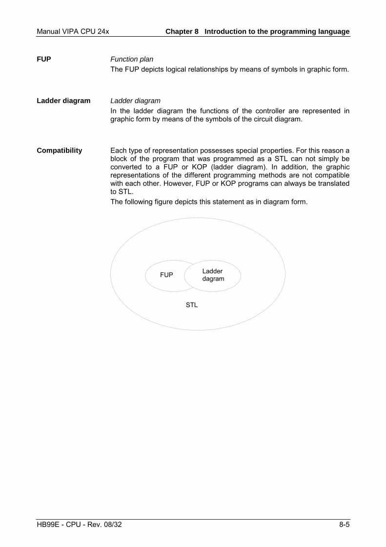
Manual VIPA CPU 24x Chapter 8 Introduction to the programming language
HB99E - CPU - Rev. 08/32 8-5
Function plan The FUP depicts logical relationships by means of symbols in graphic form.
Ladder diagram In the ladder diagram the functions of the controller are represented in graphic form by means of the symbols of the circuit diagram.
Each type of representation possesses special properties. For this reason a block of the program that was programmed as a STL can not simply be converted to a FUP or KOP (ladder diagram). In addition, the graphic representations of the different programming methods are not compatible with each other. However, FUP or KOP programs can always be translated to STL. The following figure depicts this statement as in diagram form.
FUP Ladderdagram
STL
FUP
Ladder diagram
Compatibility

Chapter 8 Introduction to the programming language Manual VIPA CPU 24x
8-6 HB99E - CPU - Rev. 08/32
The programming language differentiates between three types of operation: • primary operations • supplementary operations • system operations
Programming language Primary
operations Supplementary operations
System operations
Application area in all blocks only in the FB only in the FB Representations STL, FUP, ladder STL STL Features For users with a
good knowledge of the system
The programming language recognizes the following operand areas:
E (inputs) Interface between the process and the PLC A (outputs) Interface between the PLC and the process M (flags) Memory for intermediate binary results S (flags) Memory for intermediate binary results D (data) Memory for intermediate digital results T (timers) Memory for the implementation of timers Z (counters) Memory for the implementation of counters P (periphery) Interface between the process and the PLC K (constants) Defined constants OB, PB, SB, FB, DB
(blocks) Auxiliary resources to structure the program
Types of operation
Operand areas

Manual VIPA CPU 24x Chapter 8 Introduction to the programming language
HB99E - CPU - Rev. 08/32 8-7
Graphic representations or list with statements While the representation types FUP and KOP (ladder) provide you with the possibility to display your program graphically the statement list displays the separate instructions in list form.
Ladder diagram Statement list Function plan Programming by means of graphic symbols, e.g. circuit diagram
Programming by means of mnemotechnical abbreviations for the function descriptions
Programming by means of graphic symbols
corresponds to corresponds to corresponds to DIN 19239 DIN 19239 IEC 117-15 DIN 40700 DIN 40719
ladder diagram
STL
U EUN EU EON EO E= A
DIN 19239
Chapter 8 Introduction to the programming language Manual VIPA CPU 24x
8-8 HB99E - CPU - Rev. 08/32
Program structure
It is possible to create linear or structured programs for the CPU 24x. The following paragraphs describe these forms of the program.
For simple control applications it is sufficient to program the different operations in a single section (block). On the programmable logic controller this is the organization block 1 or "OB1". This block is processed in a cycle, i.e. when the last instruction has been processed the loop returns to the first instruction. The following must be observed: • five words are allocated to the block header when OB 1 is called. • One statement normally occupies one word of program memory.
Besides this there are 2-word statements, e.g. for the operation "Load a constant". These must be counted twice when calculating the length of the program.
• Similar to all the blocks, OB 1 must be terminated by the "BE" statement.
Programs for complex problems should be divided into separate self-contained program portions (blocks). This method has the following advantages: • large programs can be programmed in a simple and clear manner, • it is possible to standardize certain routines of the program, • changes are simplified, • program tests are simplified, • simplified implementation, • subroutine technique (calls to the respective modules from different
locations in the program).
Linear programming
Structured programming
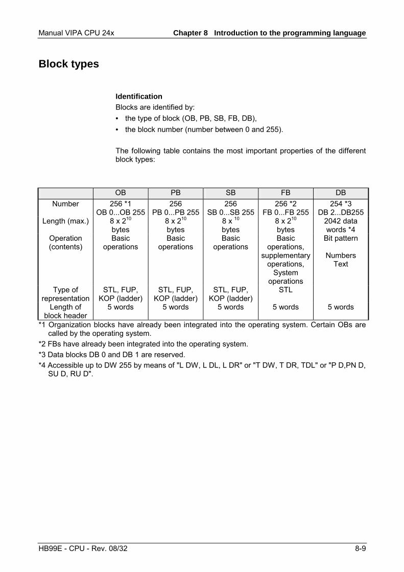
Manual VIPA CPU 24x Chapter 8 Introduction to the programming language
HB99E - CPU - Rev. 08/32 8-9
Block types
Identification Blocks are identified by: • the type of block (OB, PB, SB, FB, DB), • the block number (number between 0 and 255). The following table contains the most important properties of the different block types:
OB PB SB FB DB Number 256 *1
OB 0...OB 255 256
PB 0...PB 255256
SB 0...SB 255256 *2
FB 0...FB 255 254 *3
DB 2...DB255 Length (max.) 8 x 210
bytes 8 x 210 bytes
8 x 10 bytes
8 x 210 bytes
2042 data words *4
Operation (contents)
Basic operations
Basic operations
Basic operations
Basic operations,
supplementary operations,
System operations
Bit pattern
Numbers Text
Type of representation
STL, FUP, KOP (ladder)
STL, FUP, KOP (ladder)
STL, FUP, KOP (ladder)
STL
Length of block header
5 words 5 words 5 words 5 words 5 words
*1 Organization blocks have already been integrated into the operating system. Certain OBs are called by the operating system.
*2 FBs have already been integrated into the operating system. *3 Data blocks DB 0 and DB 1 are reserved. *4 Accessible up to DW 255 by means of "L DW, L DL, L DR" or "T DW, T DR, TDL" or "P D,PN D,
SU D, RU D".

Chapter 8 Introduction to the programming language Manual VIPA CPU 24x
8-10 HB99E - CPU - Rev. 08/32
The programming language differentiates between the following block types: Organization blocks (OB): Organization blocks represent the interface between the system program and the application program. These manage the control program: Program blocks (PB): Program blocks are used to structure the application program. They contain routines in accordance with technological or functional criteria. The PB represent the core of the application program. Sequence blocks (SB): Sequence blocks were originally used as special program blocks intended to process certain sequences in steps. However, sequences can be programmed by means of GRAPH 5 (available from Siemens). For this reason sequence blocks have lost their original importance. At present sequence blocks form a numerical expansion of program blocks and they may be used exactly like program blocks. Function blocks (FB): Function blocks are used to program functions that are re-used frequently or also for complex functions (e.g. digital functions, sequences of operations, regulators, notification functions). A single function block can be called multiple times from a block on a higher level and new operands ("configuration") can be supplied to it with every call. Data blocks (DB): Data blocks contain the (constant or variable) data used by the application program. This type of block does not contain instructions and its principal functionality differs from the other blocks.
Block types
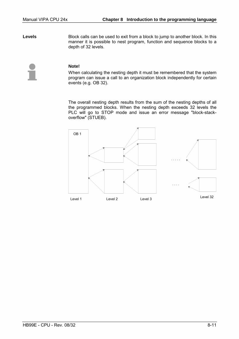
Manual VIPA CPU 24x Chapter 8 Introduction to the programming language
HB99E - CPU - Rev. 08/32 8-11
Block calls can be used to exit from a block to jump to another block. In this manner it is possible to nest program, function and sequence blocks to a depth of 32 levels.
Note! When calculating the nesting depth it must be remembered that the system program can issue a call to an organization block independently for certain events (e.g. OB 32).
The overall nesting depth results from the sum of the nesting depths of all the programmed blocks. When the nesting depth exceeds 32 levels the PLC will go to STOP mode and issue an error message "block-stack-overflow" (STUEB).
. . . . .
. . . .
Level 1 Level 2 Level 3 Level 32
OB 1
Levels

Chapter 8 Introduction to the programming language Manual VIPA CPU 24x
8-12 HB99E - CPU - Rev. 08/32
All block types consist of • block header • block body. Block header The block header always has a length of 5 words and it contains information used for the management of the blocks by the PG and data for the system program. Block body Depending on the type of block, the body can contain: • instructions (for OB, PB, SB, FB), • variable or constant data (for DB) • formal operand list (for FB). Block pre-header The programmer generates an additional block pre-header (DV, FV) for blocks of the type DB, FB. These block pre-headers contain information on the data format (for DB) or the branch marks (for FB) that can only be used by the programmer. For this reason the block pre-headers are not transferred into the memory of the CPU. The user can not access the contents of the block pre-header directly. Maximum length A block may occupy a maximum of 4096 words (1 word corresponds to 16 bits) in the program memory of the CPU.
absolute byteaddresses(ascending)
Synchronisationpattern
Block type
Block numberPG identifier
Library
NumberBlock length
The structure of the different blocks

Manual VIPA CPU 24x Chapter 8 Introduction to the programming language
HB99E - CPU - Rev. 08/32 8-13
Organization blocks Organization blocks represent the interface to the operating system and they can be divided into three groups: • an OB is called cyclically by the operating system (OB 1). • certain OBs are event or timer controlled, i.e. they are called by: − STOP→RUN - or POWER OFF→POWER-ON transitions
(OB 21, OB 22) Alarms (OB 2, OB 6). − Program or equipment error (OB 19, OB 23, OB 24, OB 27, OB 32,
OB 33, OB 34). − Timer expired (OB 10...OB 13). • Another portion represents operating functions (similar to the integrated
FBs) that can be accessed by the control program.
OB-No Function OB is called cyclically by the operating system OB 1 Cyclic program execution OBs for alarm and timer controlled program execution OB 2 Alarm: alarm generated by the digital input module OB 6 Alarm initiated by the internal timer OB 10 Timer controlled program execution (variable: 10ms...10min) OB 11 Timer controlled program execution (variable: 10ms...10min) OB 12 Timer controlled program execution (variable: 10ms...10min) OB 13 Timer controlled program execution (variable: 10ms...10min) OBs for control of the start-up behavior OB 21 In the case of a manual power on (STOP→RUN) OB 22 When power returns OBs for processing program and equipment errors OB 19 When a call is issued to a block that has not been loaded OB 23 Delayed acknowledgment in case of individual accesses to the back
panel bus(e.g. L PB, LIR etc.) OB 24 Delayed acknowledgment when the process image is being updatedOB 27 Substitution error OB 32 Transfer error in the DB or for an EDB-operation OB 33 Triggering error OB 34 Battery failure OBs, that provide operating functions OB 31 Cycle time triggering OB160 programmable timing loop OB251 PID control algorithm
OB
System OBs

Chapter 8 Introduction to the programming language Manual VIPA CPU 24x
8-14 HB99E - CPU - Rev. 08/32
The following figure shows how the organization blocks are called from the system program. It explains the significance of the OBs and shows how you can create a structured control program.
OB 21/ OB22
OB 1 PB 1 SB 1
FB 2 FB 200
Systemprogram Control program
Manual VIPA CPU 24x Chapter 8 Introduction to the programming language
HB99E - CPU - Rev. 08/32 8-15
Program blocks These blocks usually contain complete routines of the program using the instruction set of the primary operations. Features: Control functions in the routines of the program can be represented in graphic form. Call: PBs are activated by the block calls SPA and SPB. With the exception of data blocks, these operations can be programmed in all types of blocks. The block call and end limit the VKE. However, it can be transferred into the "new" block for analysis.
Sequence blocks Sequence block are special forms of program blocks that are used to process control sequences. They are treated like program blocks.
Function blocks Function blocks are used for programs that contain often repeated or complex control functions. Features: • FBs can be configured
a set of parameters can be transferred when the block is called. • In comparison with other blocks an extended set of operations is
available. • The program can only be created and documented in the form of an
STL, The programmable logic controller provides various versions of FBs; these are: • user programmable, • integrated in the operating system or, • available as software package (standard FBs). Block header In contrast to other block types FBs posses other organizational information in addition to the block header. The memory required for the organizational information is calculated from: • block header of 5 words, • block name (5 words), • block parameter during configuration (3 words per parameter).
PB
SB
FB
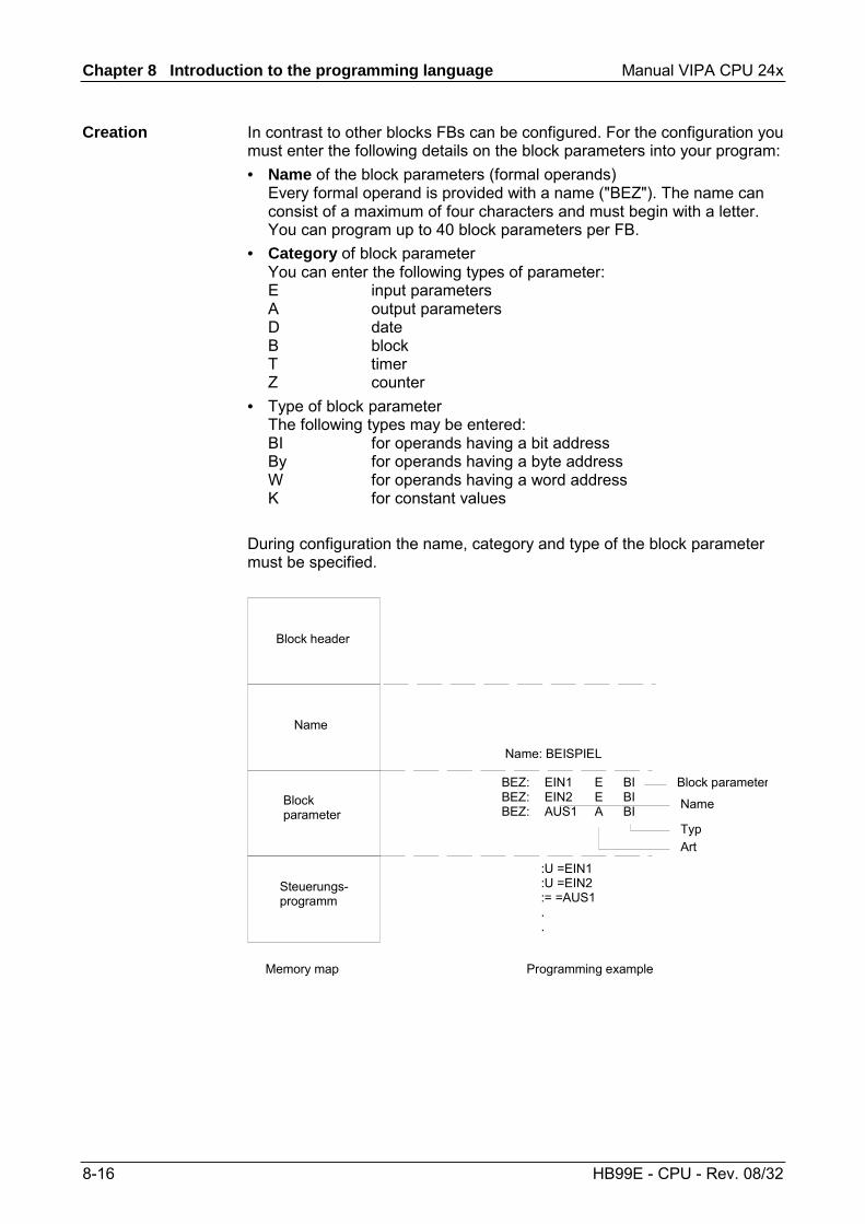
Chapter 8 Introduction to the programming language Manual VIPA CPU 24x
8-16 HB99E - CPU - Rev. 08/32
In contrast to other blocks FBs can be configured. For the configuration you must enter the following details on the block parameters into your program: • Name of the block parameters (formal operands)
Every formal operand is provided with a name ("BEZ"). The name can consist of a maximum of four characters and must begin with a letter. You can program up to 40 block parameters per FB.
• Category of block parameter You can enter the following types of parameter: E input parameters A output parameters D date B block T timer Z counter
• Type of block parameter The following types may be entered: BI for operands having a bit address By for operands having a byte address W for operands having a word address K for constant values
During configuration the name, category and type of the block parameter must be specified.
Name: BEISPIEL
BEZ:BEZ:BEZ:
EIN1EIN2AUS1
EEA
BIBIBI
Block parameter
Name
TypArt
:U =EIN1:U =EIN2:= =AUS1..
Block header
Name
Blockparameter
Steuerungs-programm
Memory map Programming example
Creation
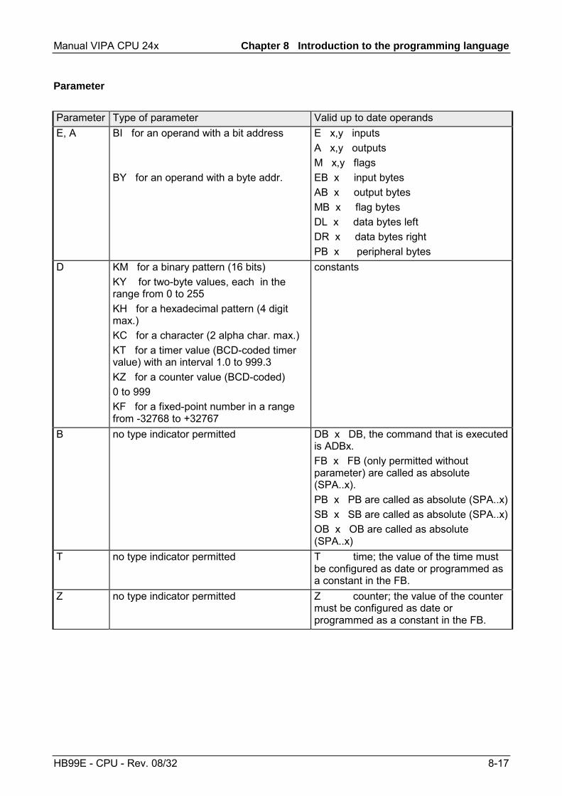
Manual VIPA CPU 24x Chapter 8 Introduction to the programming language
HB99E - CPU - Rev. 08/32 8-17
Parameter Type of parameter Valid up to date operands E, A BI for an operand with a bit address
BY for an operand with a byte addr.
E x,y inputs A x,y outputs M x,y flags EB x input bytes AB x output bytes MB x flag bytes DL x data bytes left DR x data bytes right PB x peripheral bytes
D KM for a binary pattern (16 bits) KY for two-byte values, each in the range from 0 to 255 KH for a hexadecimal pattern (4 digit max.) KC for a character (2 alpha char. max.) KT for a timer value (BCD-coded timer value) with an interval 1.0 to 999.3 KZ for a counter value (BCD-coded) 0 to 999 KF for a fixed-point number in a range from -32768 to +32767
constants
B no type indicator permitted DB x DB, the command that is executed is ADBx. FB x FB (only permitted without parameter) are called as absolute (SPA..x). PB x PB are called as absolute (SPA..x)SB x SB are called as absolute (SPA..x)OB x OB are called as absolute (SPA..x)
T no type indicator permitted T time; the value of the time must be configured as date or programmed as a constant in the FB.
Z no type indicator permitted Z counter; the value of the counter must be configured as date or programmed as a constant in the FB.
Parameter
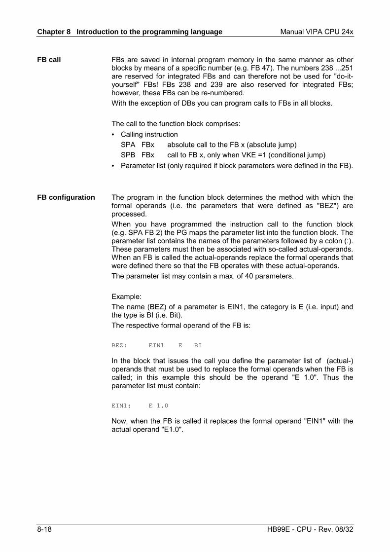
Chapter 8 Introduction to the programming language Manual VIPA CPU 24x
8-18 HB99E - CPU - Rev. 08/32
FBs are saved in internal program memory in the same manner as other blocks by means of a specific number (e.g. FB 47). The numbers 238 ...251 are reserved for integrated FBs and can therefore not be used for "do-it-yourself" FBs! FBs 238 and 239 are also reserved for integrated FBs; however, these FBs can be re-numbered. With the exception of DBs you can program calls to FBs in all blocks. The call to the function block comprises: • Calling instruction SPA FBx absolute call to the FB x (absolute jump) SPB FBx call to FB x, only when VKE =1 (conditional jump) • Parameter list (only required if block parameters were defined in the FB).
The program in the function block determines the method with which the formal operands (i.e. the parameters that were defined as "BEZ") are processed. When you have programmed the instruction call to the function block (e.g. SPA FB 2) the PG maps the parameter list into the function block. The parameter list contains the names of the parameters followed by a colon (:). These parameters must then be associated with so-called actual-operands. When an FB is called the actual-operands replace the formal operands that were defined there so that the FB operates with these actual-operands. The parameter list may contain a max. of 40 parameters. Example: The name (BEZ) of a parameter is EIN1, the category is E (i.e. input) and the type is BI (i.e. Bit). The respective formal operand of the FB is: BEZ: EIN1 E BI In the block that issues the call you define the parameter list of (actual-) operands that must be used to replace the formal operands when the FB is called; in this example this should be the operand "E 1.0". Thus the parameter list must contain: EIN1: E 1.0 Now, when the FB is called it replaces the formal operand "EIN1" with the actual operand "E1.0".
FB call
FB configuration
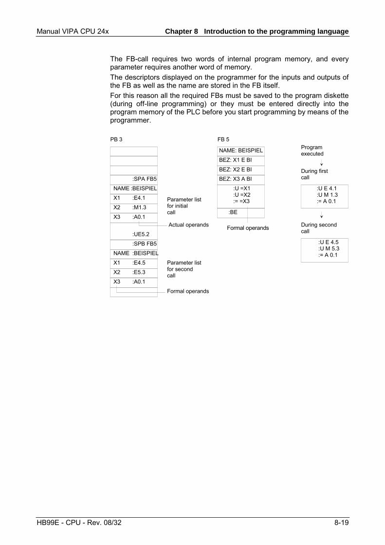
Manual VIPA CPU 24x Chapter 8 Introduction to the programming language
HB99E - CPU - Rev. 08/32 8-19
The FB-call requires two words of internal program memory, and every parameter requires another word of memory. The descriptors displayed on the programmer for the inputs and outputs of the FB as well as the name are stored in the FB itself. For this reason all the required FBs must be saved to the program diskette (during off-line programming) or they must be entered directly into the program memory of the PLC before you start programming by means of the programmer.
:SPA FB5
NAME :BEISPIEL
X1
X2
X3
:E4.1
:M1.3
:A0.1
Parameter listfor initialcall
Actual operands
:UE5.2
NAME
:SPB FB5
:BEISPIEL
X1
X2
X3
:E4.5:E5.3
:A0.1
Formal operands
Parameter listfor secondcall
PB 3 FB 5
NAME: BEISPIEL
BEZ: X1 E BI
BEZ: X2 E BI
BEZ: X3 A BI
:U =X1:U =X2:= =X3
:BE
Formal operands
:U E 4.1:U M 1.3:= A 0.1
Programexecuted
During firstcall
During secondcall
:U E 4.5:U M 5.3:= A 0.1
Chapter 8 Introduction to the programming language Manual VIPA CPU 24x
8-20 HB99E - CPU - Rev. 08/32
Data blocks Data blocks are used to store the data that must be processed by the program. The following types of data are available: • bit pattern (to depict the status of the plant), • numbers in hexadecimal, dual- or decimal notation
(timers, arithmetic results), • alphanumeric characters (reports).
The first step when programming a DB is to specify a block number between 2 and 255. DB 0 (for the operating system) and DB 1 (for the configuration of internal functions) are reserved. In this block data is saved in words. Leading zeros are used to complete the information if this consists of less than 16 bits. Data is entered from data word zero and continues in ascending sequence. A DB can accommodate up to 2042 data words. You can access all the data words up to DW 255 by means of the commands "L DW" and "T DW". Data words 256 ...2042 can only be accessed by means of the operations "LIR", TIR" and "TNB". Input stored value 0000 : KH = A13C DW0 A13C 0001 : KT = 100.2 DW1 2100 0003 : KF = +21874 DW2 5572 DBs can also be generated or cleared in the control program.
DB
Programming of DBs
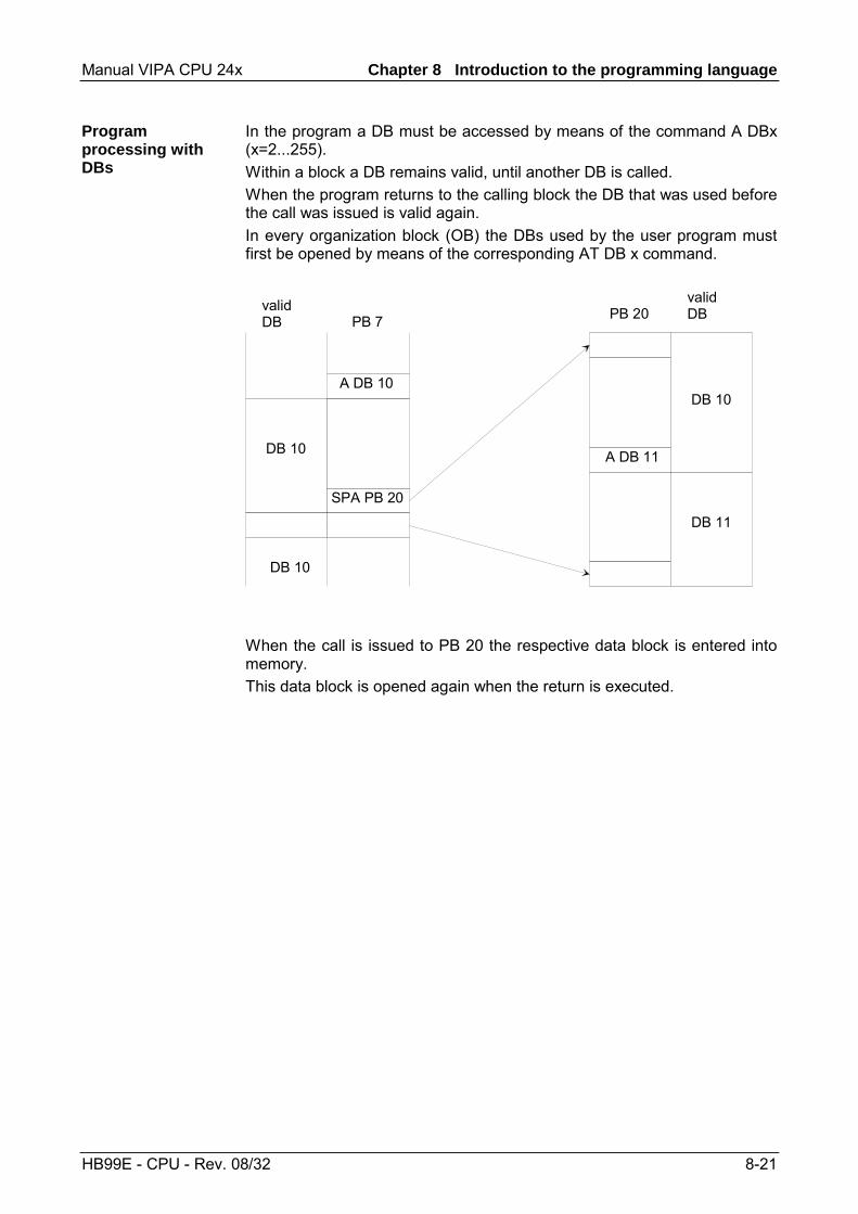
Manual VIPA CPU 24x Chapter 8 Introduction to the programming language
HB99E - CPU - Rev. 08/32 8-21
In the program a DB must be accessed by means of the command A DBx (x=2...255). Within a block a DB remains valid, until another DB is called. When the program returns to the calling block the DB that was used before the call was issued is valid again. In every organization block (OB) the DBs used by the user program must first be opened by means of the corresponding AT DB x command.
validDB PB 7
A DB 10
DB 10
SPA PB 20
DB 10
PB 20validDB
A DB 11
DB 10
DB 11
When the call is issued to PB 20 the respective data block is entered into memory. This data block is opened again when the return is executed.
Program processing with DBs
Chapter 8 Introduction to the programming language Manual VIPA CPU 24x
8-22 HB99E - CPU - Rev. 08/32
Program execution
A portion of the organization block (OB) is used to structure and to manage the control-program. These of OBs can be grouped in accordance with the following tasks: • OBs for START-UP program execution, • OB for cyclic program execution, • OBs for the in the timer controlled program execution, • OBs for (process-) alarm controlled program execution, • OBs to handle programming and equipment errors. Other OBs are also available that offer functions similar to the integrated functions (e.g. PID-control-algorithm)
During START-UP, i.e. • after a STOP→RUN transition (manual reboot) • after a POWER OFF→POWER ON transition (automatic reboots after
power returns if the CPU was in RUN mode), the operating system of the CPU issues an automatic call (provided that this was programmed) to a START-UP OB: • OB 21 (for a manual reboot) or • OB 22 (for an automatic reboot after power returns if the CPU was in
RUN mode before the power failure occurred). When you have programmed these blocks the program executed in the cycle; for this reason it is suitable for the definition of certain default system settings used once at the time the START-UP is executed, etc. If the respective START-UP-OB does not exist, the CPU jumps directly to the operating mode RUN (cyclic program execution, OB 1).
START-UP program execution

Manual VIPA CPU 24x Chapter 8 Introduction to the programming language
HB99E - CPU - Rev. 08/32 8-23
The programming of OB 22: When power returns after a power failure you want to verify that all the input and output modules are still operational. If one or more modules do not respond (not installed or faulty) the PLC must go to the operating mode STOP.
OB 22 STL Explanation :L KF +0 Output words 0, 2 and 4 :T PW 0 are set to "0". :T PW 2 :T PW 4 :L PW 6 Information of input words :L PW 8 6, 8 and 10 are stored in ACCU 1 :L PW 10 one after the other. :BE
When an input or output module does not respond to the instruction LPW or TPW the CPU goes to STOP mode when the instruction is encountered and interrupt bit QVZ (delayed acknowledgment) is set in USTACK.
Example 1
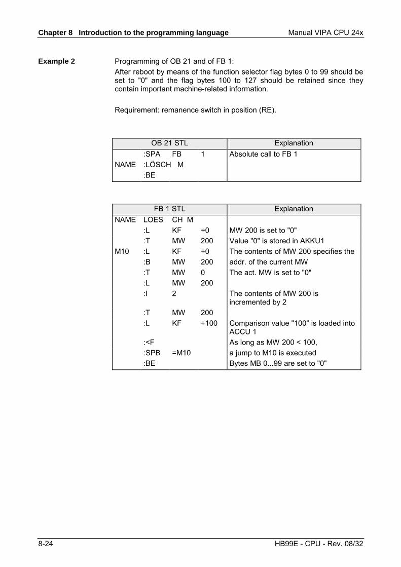
Chapter 8 Introduction to the programming language Manual VIPA CPU 24x
8-24 HB99E - CPU - Rev. 08/32
Programming of OB 21 and of FB 1: After reboot by means of the function selector flag bytes 0 to 99 should be set to "0" and the flag bytes 100 to 127 should be retained since they contain important machine-related information. Requirement: remanence switch in position (RE).
OB 21 STL Explanation :SPA FB 1 Absolute call to FB 1 NAME :LÖSCH M :BE
FB 1 STL Explanation NAME LOES CH M :L KF +0 MW 200 is set to "0" :T MW 200 Value "0" is stored in AKKU1 M10 :L KF +0 The contents of MW 200 specifies the :B MW 200 addr. of the current MW :T MW 0 The act. MW is set to "0" :L MW 200 :I 2 The contents of MW 200 is
incremented by 2 :T MW 200 :L KF +100 Comparison value "100" is loaded into
ACCU 1 :<F As long as MW 200 < 100, :SPB =M10 a jump to M10 is executed :BE Bytes MB 0...99 are set to "0"
Example 2
Manual VIPA CPU 24x Chapter 8 Introduction to the programming language
HB99E - CPU - Rev. 08/32 8-25
The operating system calls OB 1 in a cycle. The maximum time for the cyclic program is determined by the limit for the cycle-time. For the purposes of structured programming you should only include jump-operations in OB 1 (block calls). The blocks (PBs, FBs and SBs) that are called should contain the respective function units to increase readability. The CPU always contains a default OB 1!
OBs 10...13 are available for the timer controlled program execution. Time OBs are called at preset intervals by the operating system. In the system data the interval between calls can (e.g. in the START-UP-OB) be defined in multiples of 10ms. This can be changed during cyclic program execution. OB 13 is pre-set to calling interval of 100 ms. Calling intervals of 10 ms to 10 min can be defined by means of system data words 97 ...100 (range: 0 ...FFFFh) You can also configure the calling intervals in DB 1. The operating system will only access a timer OB • when the calling interval is >0 and • when the respective timer OB was programmed. Timer OBs interrupt the cyclic program after every operation. Timer OBs can not interrupt: • integrated function blocks, • the OB 6, • process alarms (OB 2). On the other hand, timer OBs can be interrupted by OB 6 or by process alarms (OB 2)! Remember that this can change the calling intervals. The priorities of the timer OBs with respect to each other are defined as follows: highest priority: OB 13 OB 12 OB 11 lowest priority: OB 10.
Cyclic program execution
Timer controlled program execution

Chapter 8 Introduction to the programming language Manual VIPA CPU 24x
8-26 HB99E - CPU - Rev. 08/32
Operation "AS" can be used to inhibit calls to all the timer OBs and enabled again by means of "A". Call requests can be queued while calls are disabled. If timer OBs should be processed in the START-UP-OB (OB 21, OB 22) you must enable alarms in the START-UP-OB by means of "AF". The nesting depth for blocks must not exceed 32 for time controlled OBs. If a timer controlled OB makes use of a "scratch-pad" that is also used in the cyclic control program these must be saved in a DB while the timer-OB is being processed.
System data word
Absolute address
High-Byte Low-Byte Default
SD 97 EAC2 Interval for OB 13 (0...FFFFh •10ms)
10 (=100ms)
SD 98 EAC4 Interval for OB 12 (0...FFFFh•10ms)
0 (=no call)
SD 99 EAC6 Interval for OB 11 (0...FFFFh •10ms)
0 (=no call)
SD 100 EAC8 Interval for OB 10 (0...FFFFh •10ms)
0 (=no call)
Defining an interval of 1s for OB13: OB 21 : SPA FB 21 NAME : ZEIT EIN : :
OB 22 : SPA FB 21 NAME : ZEIT EIN : :
FB 21 NAME : ZEIT EIN : L KF +100 : T BS 97 : BE
Please note
Parameter block for timer-OBs
Manual VIPA CPU 24x Chapter 8 Introduction to the programming language
HB99E - CPU - Rev. 08/32 8-27
In alarm controlled processing a signal coming from the process triggers the CPU to interrupt cyclic program execution and to process a specific alarm routine. After the alarm has been processed the CPU returns to the point where it was interrupted.
When a (process) alarm occurs the operating system calls OB 2. OB 2 will be executed if it was programmed. Then the system returns to the point where it was interrupted and continues the program at that point.
OB 6 is special. OB 6 is called by the operating system when the default time has expired in system data word 101 (EACAh) (provided that alarms have not been disabled by the operation "AS"). In OB 6 you must enter the program defining the reaction when the preset time ("watch dog alarm") has expired. You start the time by means of an entry in system data-word 101 (EACAh) which is only possible with the command T BS 101. Example: You have programmed a “Watchdog reaction” in OB 6. OB 6 must be called 22ms after the start of the watch dog. You can select and start the “watch dog time” by means of the operations L KF +22 T BS 101 After 22 ms OB 6 interrupts the active cyclic or time-controlled program.
Note! A running "watch dog timer" can be "retriggered" by transferring another value into system-data-word 101. Then the operating system will re-start the watch-dog timer specified by the value in AKKU 1. A running "watch-dog timer" can be stopped (call to OB 6 is inhibited!) by transferring a value "0" into system-data-word 101.
After the "watch-dog timer" was started the selected time is contained in system-data-word 101 until the call is issued to OB 6. When the programmed time has expired the operating system enters the value "0" into system-data-word 101 an and issues a call to OB 6.
Alarm controlled Program execution
(Process) alarm reaction by means of OB 2
Watchdog alarm reaction by means of OB 6

Chapter 8 Introduction to the programming language Manual VIPA CPU 24x
8-28 HB99E - CPU - Rev. 08/32
If you wish to start the “watch dog timer” you must always transfer a number (range 1...65535 or 1h...FFFFh) into system data word 101 (EACAh). • The watch dog timer can be defined in 1 ms increments, therefore the
time is selectable in a range from 1...65535ms. • The priority of OB 6 can be specified in DB 1 or in system data word
120:
15 14 13 12 11 10 9 8 7 6 5 4 3 2 1 0
SD 120x x x x x x x x x x x x x x x
Priority (in descending sequence)
0: OB 6, OB 2, OB 13...10(Default settings after overall reset)
1: OB 2, OB 6, OB 13...10 x bits defining the system properties (must not be change when the priority of OB 6 is defined). • OB 6 can not be interrupted. • OB 6 can interrupt cyclic and timer controlled programs but not an active
alarm program (OB 2)! For this reason the call to OB 6 is delayed when the “watch dog timer” expires while an alarm-OB is being processed.
• The call to OB 6 can also be delayed if: − you are using integrated FBs, − the integrated clock was configured, − PG/OP functions are active, − computer couplings or ASCII driver have been activated or − time controlled OBs have been programmed.
The following holds for OB 6:
Manual VIPA CPU 24x Chapter 8 Introduction to the programming language
HB99E - CPU - Rev. 08/32 8-29
The error reaction OBs can be used to determine the behavior of the CPU when errors are encountered. The operation that causes the delayed acknowledgment error, substitution error or the transfer error is replaced by the call to the respective error reaction OB. In these OBs you can define a specific reaction to the errors. If you have only programmed "BE" there is no reaction, i.e. the PLC does not go to STOP mode. If an OB does not exist the CPU jumps to operating mode STOP.
Reaction when a block is called that was not loaded You can use OB 19 to program the behavior of the CPU when it attempts to access a block that has not been loaded. Example: The CPU should go to STOP mode when a block is called that has not been loaded.
OB 19 STL Explanation :STP :BE
STOP instruction
If OB 19 was not programmed the control program continues with the program execution (no reaction!) immediately after the jump instruction (when the destination of the jump instruction does not exist!).
Reaction to a delayed acknowledgment during direct access to the periphery The following instructions can result in a delayed acknowledgment: L PB; L PW; T PB; T PW; LIR; TIR; TNB. The delayed acknowledgment error (QVZ) occurs when a module does not respond within 160 µs after it has been accessed. This can be caused by a programming error, a faulty module or by removing the module when the operating mode is RUN. The operating system enters the absolute module address where the QVZ occurred in system data word 103 (EACEh) and calls OB 23. If OB 23 does not exist the CPU will go to STOP mode with "QVZ".
Reaction to a delayed acknowledgment when the process image is being updated If the delayed acknowledgment error occurs while the process image is being updated then the absolute module address is saved in system data word 103 (EACEh) and a call is issued to OB 24 . If OB 24 does not exist then the CPU goes to STOP mode with "QVZ".
Processing of program and equipment errors
OB19
OB 23
OB 24
Chapter 8 Introduction to the programming language Manual VIPA CPU 24x
8-30 HB99E - CPU - Rev. 08/32
Reaction to a substitution error A substitution error (SUF) can occur, if a formal parameter description is altered in a FB after a call has been programmed ("SPA FBx", "SPB FBx"). The operating system interrupts the control program when a substitution error is recognized and processes the OB instead of the substitution operation. If OB 27 does not exist the CPU goes to STOP mode with the USTACK error flag "SUF".
Reaction to transfer error A transfer error (TRAF) is detected if: − data words are accessed without first calling a data block (A DB), − if in the operations L DW; T DW; P D; PN D; SU D; RU D; etc. the
parameter is larger than the length of the data block that was opened, − with the command E DB (create data block) the unused data memory is
not large enough to generate the specified data block. Reaction to transfer errors: the operating system interrupts the processing of the operation where the transfer error occurred and processes OB 32 instead. If OB 32 should not exist the CPU goes to STOP mode with the USTACK error flag "TRAF".
Watchdog error A watchdog error is returned if: • one of the organization blocks OB 6 and OB 10 to OB 13 are being
processed and the watchdog alarm or timer expired alarm occurs again, • if the watchdog alarm or timer expired alarm occurs again while alarms
are inhibited. When a watchdog error occurs OB 33is called. The error code that defines the watchdog error is entered into AKKU 1: 1 Processing of OB 6 2 Processing of OB 13 3 Processing of OB 12 4 Processing of OB 11 5 Processing of OB 10 No reaction will occur for the returned watchdog error if the watchdog error OB 33 was not programmed.
OB 27
OB 32
OB 33
Manual VIPA CPU 24x Chapter 8 Introduction to the programming language
HB99E - CPU - Rev. 08/32 8-31
Reactions to the signal BAU (battery failure) The PLC continuously monitors the status of the battery in the power supply. If the battery should fail (BAU) OB 34 is processed ahead of every cycle. You must program the reaction to a battery failure into OB 34. No reaction occurs if OB 34 was not programmed.
Note! When the internal battery fails the hardware must be returned to VIPA for repair.
Other OBs that provide operational functions are: OB 160 timer loop OB 251 PID control algorithm. For a description please refer to the chapter on "Integrated blocks".
OB 34
Chapter 8 Introduction to the programming language Manual VIPA CPU 24x
8-32 HB99E - CPU - Rev. 08/32
Processing of blocks
The previous paragraphs contain a description on the application of the different blocks. Previously programmed blocks can be changed. We will only briefly describe the changes that can be implements. The respective procedure is described in the instruction manual for the PG as well as the description of the programmers software.
Changes to programs can be implemented in the following PG functions - independent of the type of block: • EINGABE (input) • AUSGABE (output) • STATUS. You can implement the following modifications in these functions: • remove, insert or overwrite instructions, • insert or erase networks.
Program changes refer to the contents of a block. You can also delete entire blocks or you can overwrite them. This does not erase the blocks in program memory but it merely invalidates them. These memory areas cannot be overwritten. This can have the result that new blocks are no longer accepted; an error message is issued via the PG that indicates "no memory". You can clear this message by compressing the memory contents of the PLC.
Changes to the program
Block changes
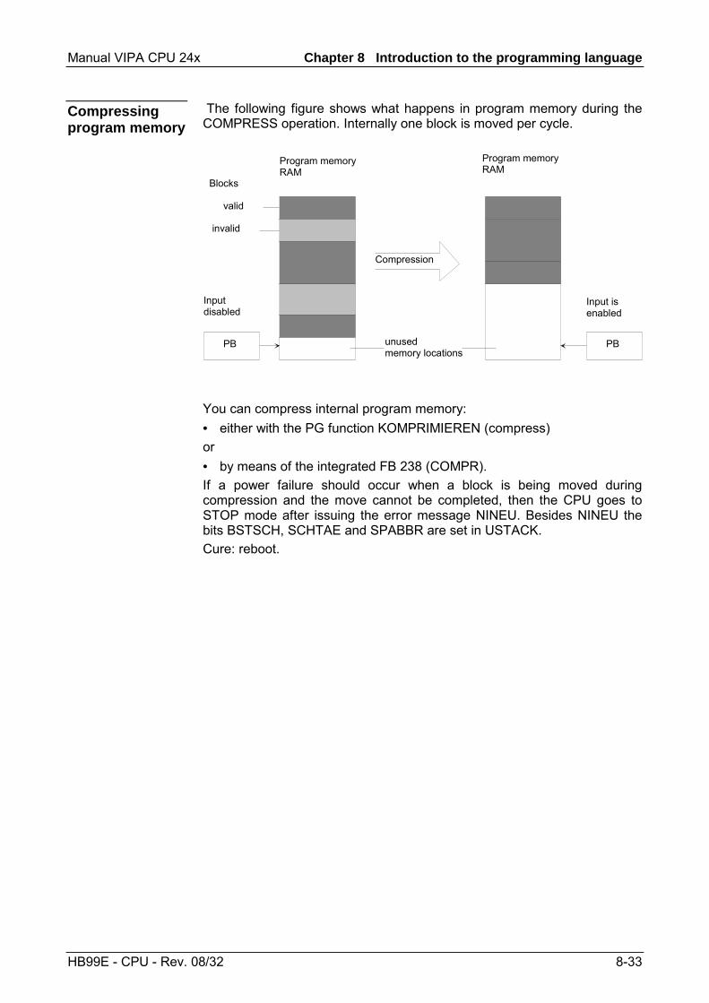
Manual VIPA CPU 24x Chapter 8 Introduction to the programming language
HB99E - CPU - Rev. 08/32 8-33
The following figure shows what happens in program memory during the COMPRESS operation. Internally one block is moved per cycle.
Blocks
valid
invalid
Program memory RAM
PB
Input disabled
unused memory locations
PB
Program memoryRAM
Compression
Input isenabled
You can compress internal program memory: • either with the PG function KOMPRIMIEREN (compress) or • by means of the integrated FB 238 (COMPR). If a power failure should occur when a block is being moved during compression and the move cannot be completed, then the CPU goes to STOP mode after issuing the error message NINEU. Besides NINEU the bits BSTSCH, SCHTAE and SPABBR are set in USTACK. Cure: reboot.
Compressing program memory
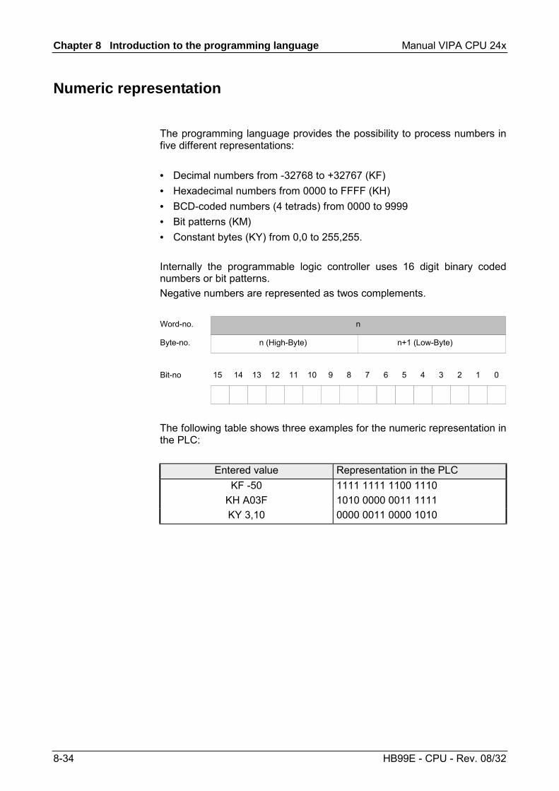
Chapter 8 Introduction to the programming language Manual VIPA CPU 24x
8-34 HB99E - CPU - Rev. 08/32
Numeric representation
The programming language provides the possibility to process numbers in five different representations: • Decimal numbers from -32768 to +32767 (KF) • Hexadecimal numbers from 0000 to FFFF (KH) • BCD-coded numbers (4 tetrads) from 0000 to 9999 • Bit patterns (KM) • Constant bytes (KY) from 0,0 to 255,255. Internally the programmable logic controller uses 16 digit binary coded numbers or bit patterns. Negative numbers are represented as twos complements.
0123456789101112131415Bit-no
n (High-Byte) n+1 (Low-Byte)Byte-no.
Word-no. n
The following table shows three examples for the numeric representation in the PLC:
Entered value Representation in the PLC KF -50 1111 1111 1100 1110
KH A03F 1010 0000 0011 1111 KY 3,10 0000 0011 0000 1010
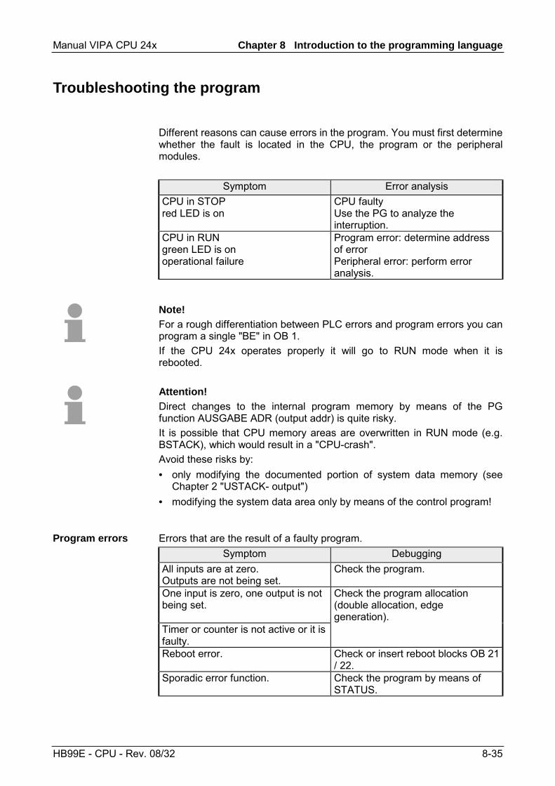
Manual VIPA CPU 24x Chapter 8 Introduction to the programming language
HB99E - CPU - Rev. 08/32 8-35
Troubleshooting the program
Different reasons can cause errors in the program. You must first determine whether the fault is located in the CPU, the program or the peripheral modules.
Symptom Error analysis CPU in STOP red LED is on
CPU faulty Use the PG to analyze the interruption.
CPU in RUN green LED is on operational failure
Program error: determine address of error Peripheral error: perform error analysis.
Note! For a rough differentiation between PLC errors and program errors you can program a single "BE" in OB 1. If the CPU 24x operates properly it will go to RUN mode when it is rebooted. Attention! Direct changes to the internal program memory by means of the PG function AUSGABE ADR (output addr) is quite risky. It is possible that CPU memory areas are overwritten in RUN mode (e.g. BSTACK), which would result in a "CPU-crash". Avoid these risks by: • only modifying the documented portion of system data memory (see
Chapter 2 "USTACK- output") • modifying the system data area only by means of the control program!
Errors that are the result of a faulty program. Symptom Debugging
All inputs are at zero. Check the program. Outputs are not being set. One input is zero, one output is not being set.
Check the program allocation (double allocation, edge generation).
Timer or counter is not active or it is faulty.
Reboot error. Check or insert reboot blocks OB 21 / 22.
Sporadic error function. Check the program by means of STATUS.
Program errors

Chapter 8 Introduction to the programming language Manual VIPA CPU 24x
8-36 HB99E - CPU - Rev. 08/32

Manual VIPA CPU 24x Chapter 9 Operations
HB99E - CPU - Rev. 08/32 9-1
Chapter 9 Operations
This chapter contains a description of the instruction set. Primary operations, supplementary operations and the system operations are explained by means of examples.
Topic Page Chapter 9 Operations....................................................................... 9-1
Introduction .......................................................................................... 9-2 Primary operations ............................................................................... 9-3 Supplementary operations.................................................................. 9-40 System operations.............................................................................. 9-66 Setting of flags ................................................................................... 9-76 Programming examples...................................................................... 9-79
Outline
Contents
Chapter 9 Operations Manual VIPA CPU 24x
9-2 HB99E - CPU - Rev. 08/32
Introduction
The programming language can distinguish between three types of operation: • Primary operations comprise functions that can be executed by
organization, program, sequence and function blocks. With the exception of the addition (+F), the subtraction (-F) and the organizational operations these can be displayed in all types of representation (STL, FUP, KOP).
• Supplemental operations comprise complex functions like substitution
instructions, test functions, shift and conversion operations. These can only be entered and displayed in the STL representation.
• System operations access the operating system. These should only be
used by experienced programmers. These can only be entered and displayed in the STL representation.

Manual VIPA CPU 24x Chapter 9 Operations
HB99E - CPU - Rev. 08/32 9-3
Primary operations
The following table contains a list of the different operations; this is followed by the examples.
Operation Operand Description O OR-operations on AND-functions
The result of the next AND-operation is combined with the current AND after OR.
U( AND-operation of term in brackets The result of the term in brackets is combined with the previous result after the AND.
O( OR-operation of terms in brackets The result of the term in brackets is combined with the previous result after the OR.
) Close brackets This operation terminates the term in brackets..
U x x AND-operation, check for signal status "1" The result is "1" if the respective operand has signal status "1". Otherwise the result is “0”. This result is ANDed with the result in the processor. *1
O x x OR-operation, check for signal status "1" The result is "1" if the respective operand has signal status "1". Otherwise the result is “0”. This result is ORed with the result in the processor. *1
UN x x UND-operation, Check for signal status "0" The result is “1” if the respective operand has signal status “0”. Otherwise the result is “0”. This result is ANDed with the result in the processor. *1
ON x x OR-operation, Check for signal status "0" The result is “1” if the respective operand has signal status “0”. Otherwise the result is “0”. This result is ORed with the result in the processor. *1
Identifier Parameter CPU 241...244 E 0.0...127.7 A 0.0...127.7 M 0.0 255.7 S 0.0...1023.7 T 0...127 Z 0...127 * 1 If the check follows immediately after an operation that places constraints on the result (first
check) then the result of the check is used as the new result of the logical operation.
Logical operations
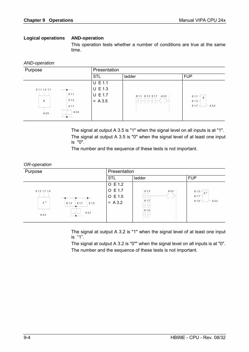
Chapter 9 Operations Manual VIPA CPU 24x
9-4 HB99E - CPU - Rev. 08/32
AND-operation This operation tests whether a number of conditions are true at the same time.
AND-operation Purpose Presentation STL ladder FUP
U E 1.1 U E 1.3 U E 1.7 = A 3.5
The signal at output A 3.5 is "1" when the signal level on all inputs is at "1". The signal at output A 3.5 is "0" when the signal level of at least one input is "0". The number and the sequence of these tests is not important.
OR-operation Purpose Presentation STL ladder FUP
O E 1.2 O E 1.7 O E 1.5 = A 3.2
The signal at output A 3.2 is "1" when the signal level of at least one input is “1”. The signal at output A 3.2 is "0"" when the signal level on all inputs is at "0". The number and the sequence of these tests is not important.
Logical operations
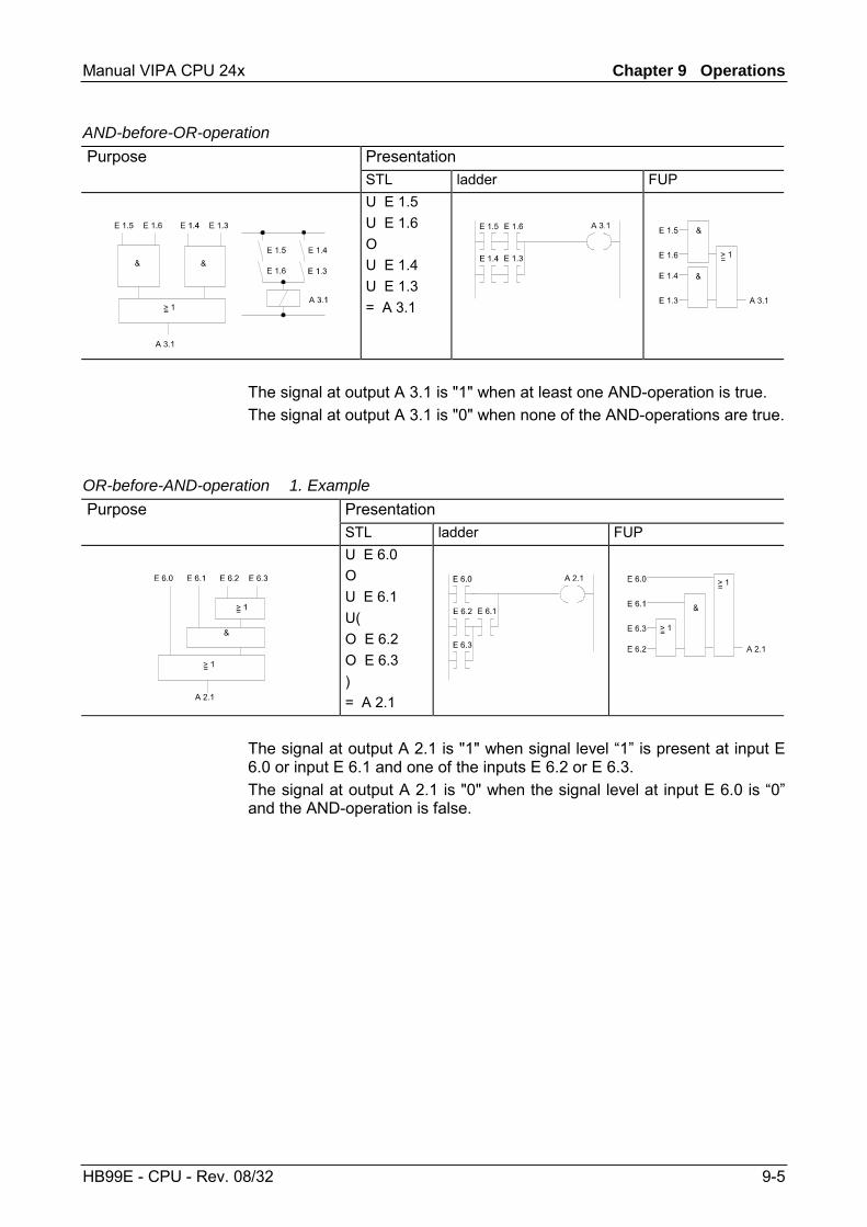
Manual VIPA CPU 24x Chapter 9 Operations
HB99E - CPU - Rev. 08/32 9-5
AND-before-OR-operation Purpose Presentation STL ladder FUP
U E 1.5 U E 1.6 O U E 1.4 U E 1.3 = A 3.1
The signal at output A 3.1 is "1" when at least one AND-operation is true. The signal at output A 3.1 is "0" when none of the AND-operations are true.
OR-before-AND-operation 1. Example Purpose Presentation STL ladder FUP
U E 6.0 O U E 6.1 U( O E 6.2 O E 6.3 ) = A 2.1
The signal at output A 2.1 is "1" when signal level “1” is present at input E 6.0 or input E 6.1 and one of the inputs E 6.2 or E 6.3. The signal at output A 2.1 is "0" when the signal level at input E 6.0 is “0” and the AND-operation is false.

Chapter 9 Operations Manual VIPA CPU 24x
9-6 HB99E - CPU - Rev. 08/32
OR-before-AND-operation 2.Example Purpose Presentation STL ladder FUP
U( O E 1.4 O E 1.5 ) U( O E 2.0 O E 2.1 ) = A 3.0
The signal at output A 3.0 is "1" when not OR-operations are true. The signal at output A 3.0 is "0" when at least one OR-operation is false.
Check for signal status "0" Purpose Presentation STL ladder FUP
U E 1.5 UN E 1.6 = A 3.0
The signal at output A 3.0 is "1" only if input E 1.5 is at signal level "1" (normally open contact closed) and input E 1.6 is at signal level "0" (normally closed contact not actuated).
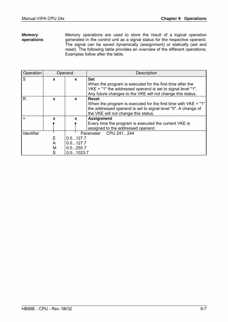
Manual VIPA CPU 24x Chapter 9 Operations
HB99E - CPU - Rev. 08/32 9-7
Memory operations are used to store the result of a logical operation generated in the control unit as a signal status for the respective operand. The signal can be saved dynamically (assignment) or statically (set and reset). The following table provides an overview of the different operations; Examples follow after the table.
Operation Operand Description S x x Set
When the program is executed for the first time after the VKE = "1" the addressed operand is set to signal level "1". Any future changes to the VKE will not change this status.
R x x Reset When the program is executed for the first time with VKE = "1" the addressed operand is set to signal level "0". A change of the VKE will not change this status.
= x x Assignment Every time the program is executed the current VKE is assigned to the addressed operand.
Identifier E A M S
Parameter CPU 241...244 0.0...127.7 0.0...127.7 0.0...255.7 0.0...1023.7
Memory operations
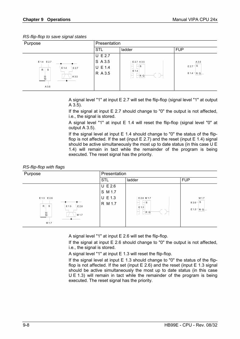
Chapter 9 Operations Manual VIPA CPU 24x
9-8 HB99E - CPU - Rev. 08/32
RS-flip-flop to save signal states Purpose Presentation STL ladder FUP
U E 2.7 S A 3.5 U E 1.4 R A 3.5
A signal level "1" at input E 2.7 will set the flip-flop (signal level "1" at output A 3.5). If the signal at input E 2.7 should change to "0" the output is not affected, i.e., the signal is stored. A signal level "1" at input E 1.4 will reset the flip-flop (signal level "0" at output A 3.5). If the signal level at input E 1.4 should change to "0" the status of the flip-flop is not affected. If the set (input E 2.7) and the reset (input E 1.4) signal should be active simultaneously the most up to date status (in this case U E 1.4) will remain in tact while the remainder of the program is being executed. The reset signal has the priority.
RS-flip-flop with flags Purpose Presentation STL ladder FUP
U E 2.6 S M 1.7 U E 1.3 R M 1.7
A signal level "1" at input E 2.6 will set the flip-flop. If the signal at input E 2.6 should change to "0" the output is not affected, i.e., the signal is stored. A signal level "1" at input E 1.3 will reset the flip-flop. If the signal level at input E 1.3 should change to "0" the status of the flip-flop is not affected. If the set (input E 2.6) and the reset (input E 1.3 signal should be active simultaneously the most up to date status (in this case U E 1.3) will remain in tact while the remainder of the program is being executed. The reset signal has the priority.
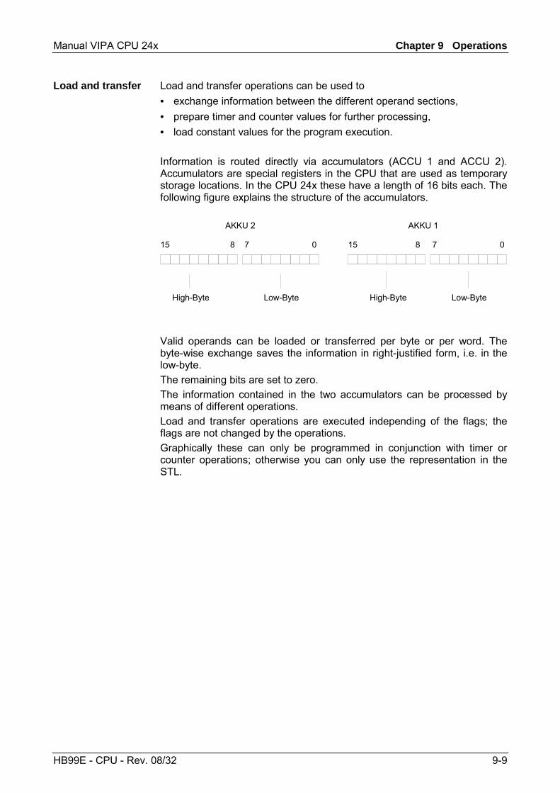
Manual VIPA CPU 24x Chapter 9 Operations
HB99E - CPU - Rev. 08/32 9-9
Load and transfer operations can be used to • exchange information between the different operand sections, • prepare timer and counter values for further processing, • load constant values for the program execution. Information is routed directly via accumulators (ACCU 1 and ACCU 2). Accumulators are special registers in the CPU that are used as temporary storage locations. In the CPU 24x these have a length of 16 bits each. The following figure explains the structure of the accumulators.
AKKU 2 AKKU 1
0 07 78 815 15
High-Byte High-ByteLow-Byte Low-Byte Valid operands can be loaded or transferred per byte or per word. The byte-wise exchange saves the information in right-justified form, i.e. in the low-byte. The remaining bits are set to zero. The information contained in the two accumulators can be processed by means of different operations. Load and transfer operations are executed independing of the flags; the flags are not changed by the operations. Graphically these can only be programmed in conjunction with timer or counter operations; otherwise you can only use the representation in the STL.
Load and transfer
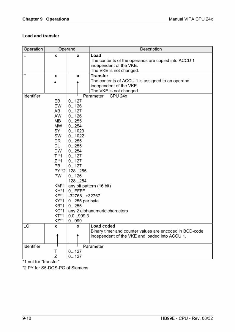
Chapter 9 Operations Manual VIPA CPU 24x
9-10 HB99E - CPU - Rev. 08/32
Operation Operand Description L x x Load
The contents of the operands are copied into ACCU 1 independent of the VKE. The VKE is not changed.
T x x Transfer The contents of ACCU 1 is assigned to an operand independent of the VKE. The VKE is not changed.
Identifier EB EW AB AW MB MW SY SW DR DL DW T *1 Z *1 PB PY *2 PW KM*1 KH*1 KF*1 KY*1 KB*1 KC*1 KT*1 KZ*1
Parameter CPU 24x 0...127 0...126 0...127 0...126 0...255 0...254 0...1023 0...1022 0...255 0...255 0...254 0...127 0...127 0...127 128...255 0...126 128...254 any bit pattern (16 bit) 0...FFFF -32768...+32767 0...255 per byte 0...255 any 2 alphanumeric characters 0.0...999.3 0...999
LC x x Load coded Binary timer and counter values are encoded in BCD-code independent of the VKE and loaded into ACCU 1.
Identifier T Z
Parameter 0...127 0...127
*1 not for "transfer" *2 PY for S5-DOS-PG of Siemens
Load and transfer
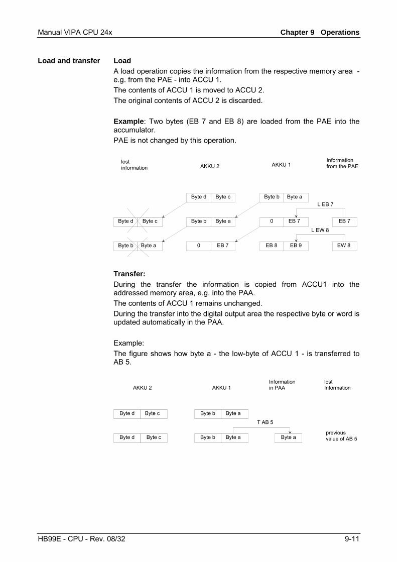
Manual VIPA CPU 24x Chapter 9 Operations
HB99E - CPU - Rev. 08/32 9-11
Load A load operation copies the information from the respective memory area - e.g. from the PAE - into ACCU 1. The contents of ACCU 1 is moved to ACCU 2. The original contents of ACCU 2 is discarded. Example: Two bytes (EB 7 and EB 8) are loaded from the PAE into the accumulator. PAE is not changed by this operation.
Byte d
Byte d
Byte c
Byte c
Byte a
Byte aByte b
Byte b
Byte b Byte a 0
0
EB 7
EB 7 EB 7
EW 8EB 8 EB 9
L EB 7
L EW 8
lost information AKKU 2 AKKU 1
Informationfrom the PAE
Transfer: During the transfer the information is copied from ACCU1 into the addressed memory area, e.g. into the PAA. The contents of ACCU 1 remains unchanged. During the transfer into the digital output area the respective byte or word is updated automatically in the PAA. Example: The figure shows how byte a - the low-byte of ACCU 1 - is transferred to AB 5.
Byte d
Byte d
Byte c
Byte c Byte b
Byte b Byte a
Byte a
AKKU 2 AKKU 1
Byte a
Informationin PAA
lostInformation
previous value of AB 5
T AB 5
Load and transfer
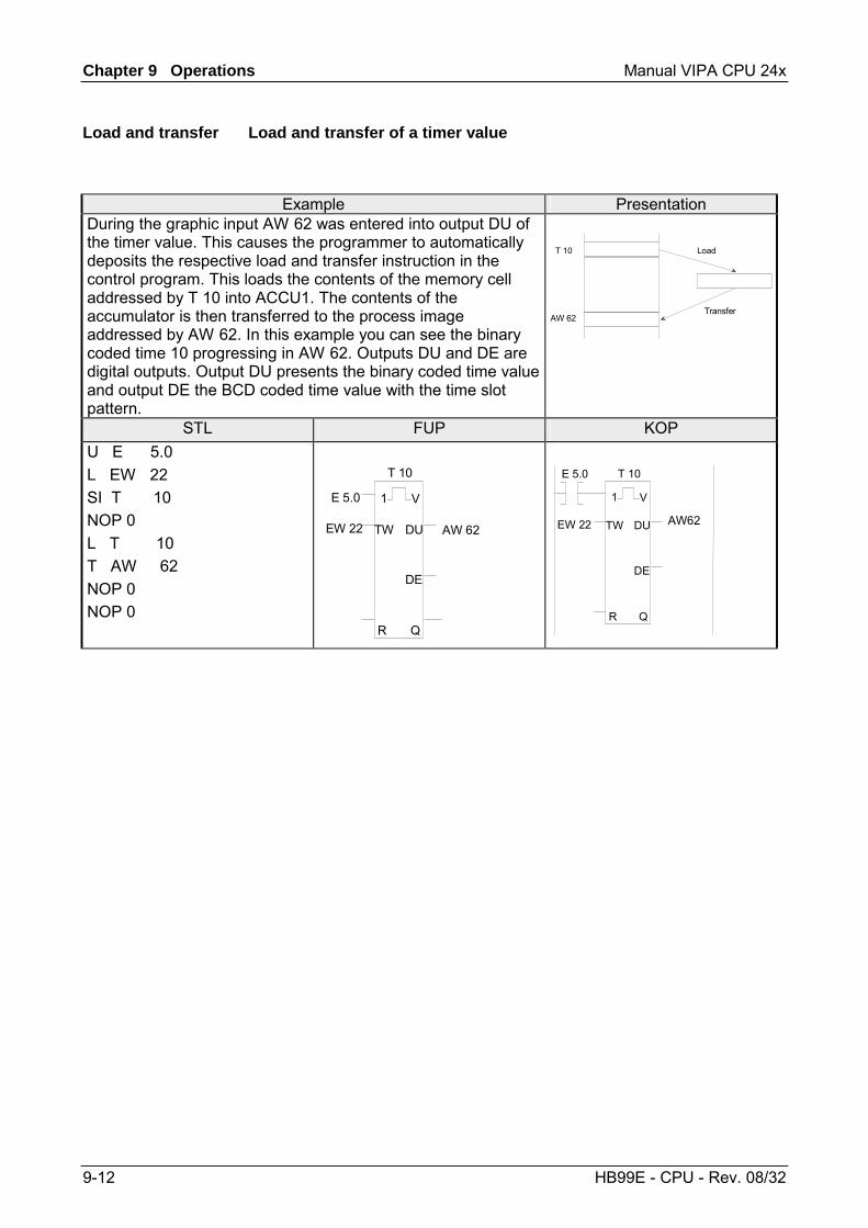
Chapter 9 Operations Manual VIPA CPU 24x
9-12 HB99E - CPU - Rev. 08/32
Load and transfer of a timer value
Example Presentation During the graphic input AW 62 was entered into output DU of the timer value. This causes the programmer to automatically deposits the respective load and transfer instruction in the control program. This loads the contents of the memory cell addressed by T 10 into ACCU1. The contents of the accumulator is then transferred to the process image addressed by AW 62. In this example you can see the binary coded time 10 progressing in AW 62. Outputs DU and DE are digital outputs. Output DU presents the binary coded time value and output DE the BCD coded time value with the time slot pattern.
T 10
AW 62
Load
Transfer
STL FUP KOP U E 5.0 L EW 22 SI T 10 NOP 0 L T 10 T AW 62 NOP 0 NOP 0
T 10
R Q
DUTW
DE
1E 5.0
EW 22
V
AW 62
E 5.0
EW 22
T 10
R Q
DUTW
DE
1 V
AW62
Load and transfer
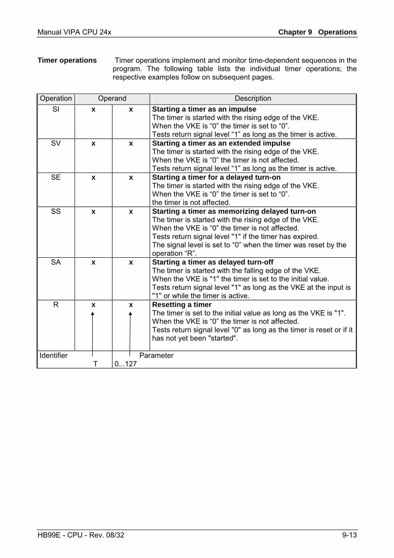
Manual VIPA CPU 24x Chapter 9 Operations
HB99E - CPU - Rev. 08/32 9-13
Timer operations implement and monitor time-dependent sequences in the program. The following table lists the individual timer operations; the respective examples follow on subsequent pages.
Operation Operand Description SI x x Starting a timer as an impulse
The timer is started with the rising edge of the VKE. When the VKE is “0” the timer is set to “0”. Tests return signal level “1” as long as the timer is active.
SV x x Starting a timer as an extended impulse The timer is started with the rising edge of the VKE. When the VKE is “0” the timer is not affected. Tests return signal level “1” as long as the timer is active.
SE x x Starting a timer for a delayed turn-on The timer is started with the rising edge of the VKE. When the VKE is “0” the timer is set to “0”. the timer is not affected.
SS x x Starting a timer as memorizing delayed turn-on The timer is started with the rising edge of the VKE. When the VKE is “0” the timer is not affected. Tests return signal level "1" if the timer has expired. The signal level is set to “0” when the timer was reset by the operation “R”.
SA x x Starting a timer as delayed turn-off The timer is started with the falling edge of the VKE. When the VKE is "1" the timer is set to the initial value. Tests return signal level "1" as long as the VKE at the input is "1" or while the timer is active.
R x x Resetting a timer The timer is set to the initial value as long as the VKE is "1". When the VKE is “0” the timer is not affected. Tests return signal level "0" as long as the timer is reset or if it has not yet been "started".
Identifier T
Parameter 0...127
Timer operations
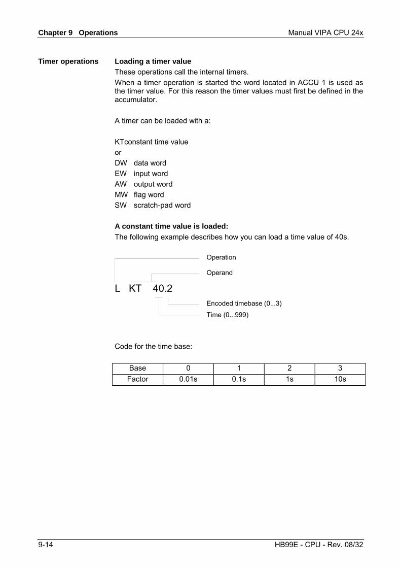
Chapter 9 Operations Manual VIPA CPU 24x
9-14 HB99E - CPU - Rev. 08/32
Loading a timer value These operations call the internal timers. When a timer operation is started the word located in ACCU 1 is used as the timer value. For this reason the timer values must first be defined in the accumulator. A timer can be loaded with a: KTconstant time value or DW data word EW input word AW output word MW flag word SW scratch-pad word A constant time value is loaded: The following example describes how you can load a time value of 40s.
L KT 40.2
Operation
Operand
Encoded timebase (0...3)
Time (0...999) Code for the time base:
Base 0 1 2 3 Factor 0.01s 0.1s 1s 10s
Timer operations

Manual VIPA CPU 24x Chapter 9 Operations
HB99E - CPU - Rev. 08/32 9-15
Example: KT 40.2 corresponds to 40 x 1s Tolerances: The time values have a tolerance equal to the time base. Examples Operand Time interval Possible KT 400.1 400 x 0,1s - 0,1s 39,9s...40s values for KT 40.2 40 x 1s - 1s 39s...40s the 40s time KT 4.3 4 x 10s - 10s 30s...40s
Note! You must always use the lowest possible time base
A time value is loaded as input, output, flag or data word: Load instruction: L DW 2 Data word 2 contains the time 638s in BCD-coded form. Bits 14 and 15 are not significant for the time value.
1 1 1 1 1 10 0 0 0 0 0 0 0
Timebase 3-digit time(BCD-coded)
01115 Bit
DW 2
Code for the time base:
Base 00 01 10 11 Factor 0.01s 0.1s 1s 10s
Timer operations

Chapter 9 Operations Manual VIPA CPU 24x
9-16 HB99E - CPU - Rev. 08/32
Data word 2 can also be described by the control program. Example: the value 270 x 100ms must be stored in data word 2 of DB 3. A DB 3 L KT 270.1 T DW 2
Output of the up to date time: The current time can be loaded into ACCU 1 by means of a load operation for further processing. The “Load coded” operation is suitable for outputs to a numerical display.
Current time in T1
LT 1 LCT 1
binary time Timebase
three-digit timeBCD-coded
bits containing "0"
AKKU 1
Timer operations
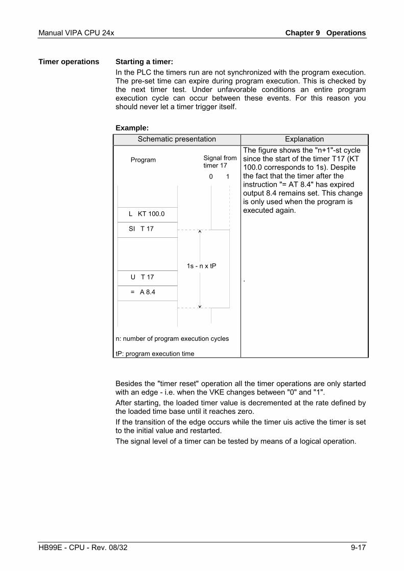
Manual VIPA CPU 24x Chapter 9 Operations
HB99E - CPU - Rev. 08/32 9-17
Starting a timer: In the PLC the timers run are not synchronized with the program execution. The pre-set time can expire during program execution. This is checked by the next timer test. Under unfavorable conditions an entire program execution cycle can occur between these events. For this reason you should never let a timer trigger itself. Example:
Schematic presentation Explanation
L KT 100.0
SI T 17
U T 17
= A 8.4
Program
0 1
Signal fromtimer 17
1s - n x tP
n: number of program execution cycles
tP: program execution time
The figure shows the "n+1"-st cycle since the start of the timer T17 (KT 100.0 corresponds to 1s). Despite the fact that the timer after the instruction "= AT 8.4" has expired output 8.4 remains set. This change is only used when the program is executed again. .
Besides the "timer reset" operation all the timer operations are only started with an edge - i.e. when the VKE changes between "0" and "1". After starting, the loaded timer value is decremented at the rate defined by the loaded time base until it reaches zero. If the transition of the edge occurs while the timer uis active the timer is set to the initial value and restarted. The signal level of a timer can be tested by means of a logical operation.
Timer operations
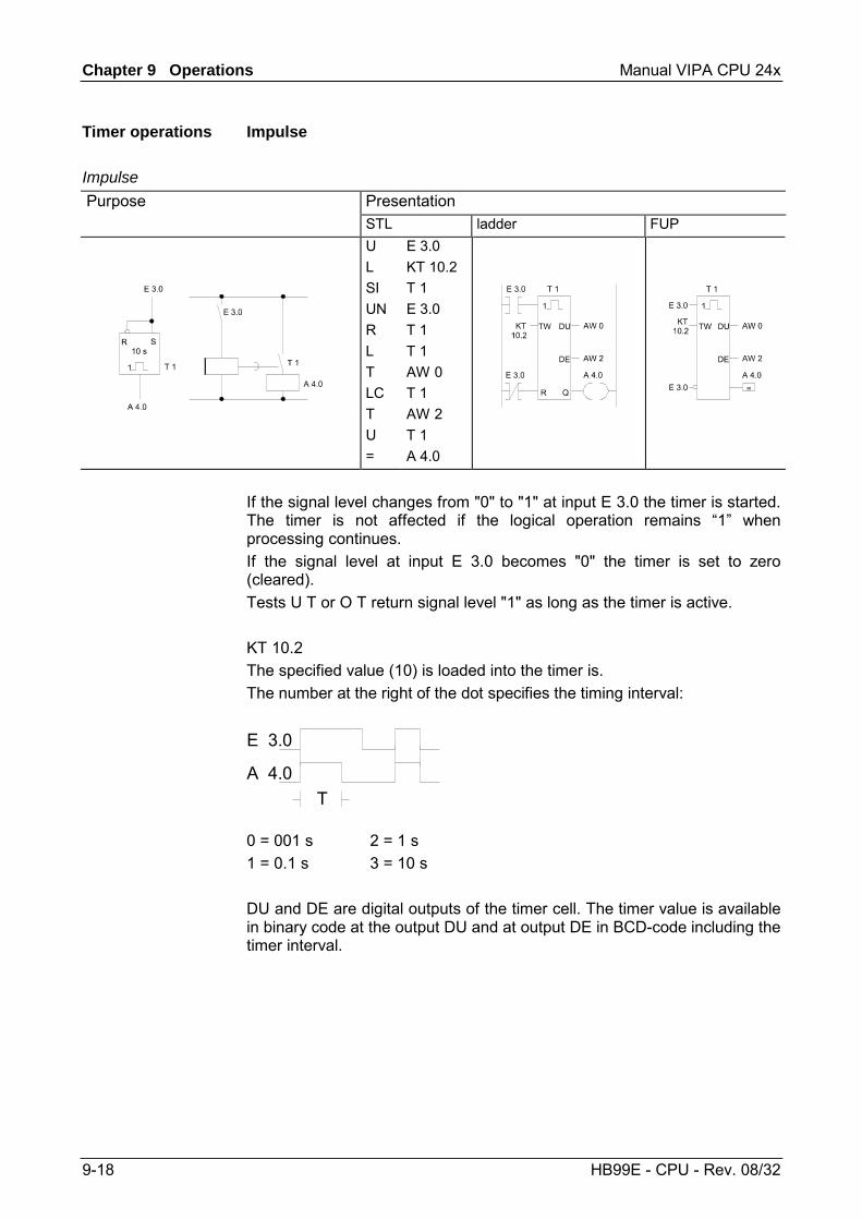
Chapter 9 Operations Manual VIPA CPU 24x
9-18 HB99E - CPU - Rev. 08/32
Impulse
Impulse Purpose Presentation STL ladder FUP
U L SI UN R L T LC T U =
E 3.0 KT 10.2 T 1 E 3.0 T 1 T 1 AW 0 T 1 AW 2 T 1 A 4.0
If the signal level changes from "0" to "1" at input E 3.0 the timer is started. The timer is not affected if the logical operation remains “1” when processing continues. If the signal level at input E 3.0 becomes "0" the timer is set to zero (cleared). Tests U T or O T return signal level "1" as long as the timer is active. KT 10.2 The specified value (10) is loaded into the timer is. The number at the right of the dot specifies the timing interval: E 3.0
A 4.0T
0 = 001 s 2 = 1 s 1 = 0.1 s 3 = 10 s DU and DE are digital outputs of the timer cell. The timer value is available in binary code at the output DU and at output DE in BCD-code including the timer interval.
Timer operations
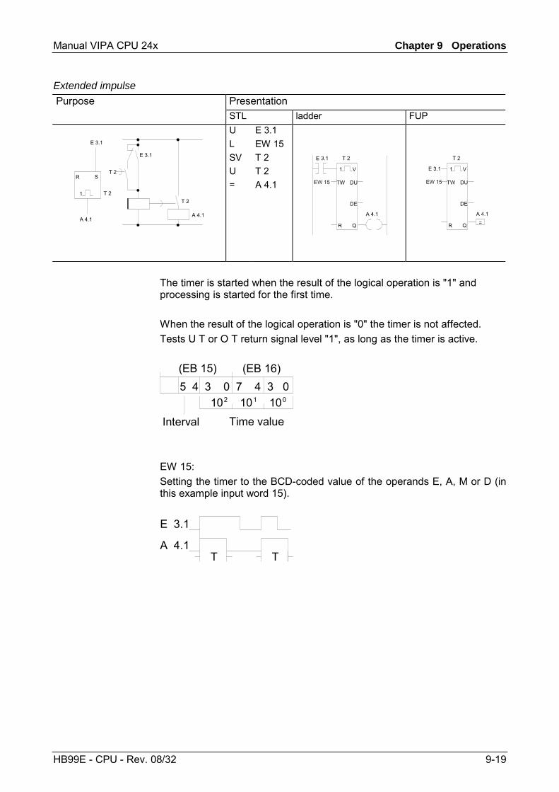
Manual VIPA CPU 24x Chapter 9 Operations
HB99E - CPU - Rev. 08/32 9-19
Extended impulse Purpose Presentation STL ladder FUP
A 4.1
E 3.1
T 2
SR
1
E 3.1
A 4.1
T 2
T 2
U L SV U =
E 3.1 EW 15 T 2 T 2 A 4.1
The timer is started when the result of the logical operation is "1" and processing is started for the first time. When the result of the logical operation is "0" the timer is not affected. Tests U T or O T return signal level "1", as long as the timer is active.
(EB 15) (EB 16)5 4 3 0 7 4 3 0
102 100101
Interval Time value EW 15: Setting the timer to the BCD-coded value of the operands E, A, M or D (in this example input word 15). E 3.1
A 4.1T T
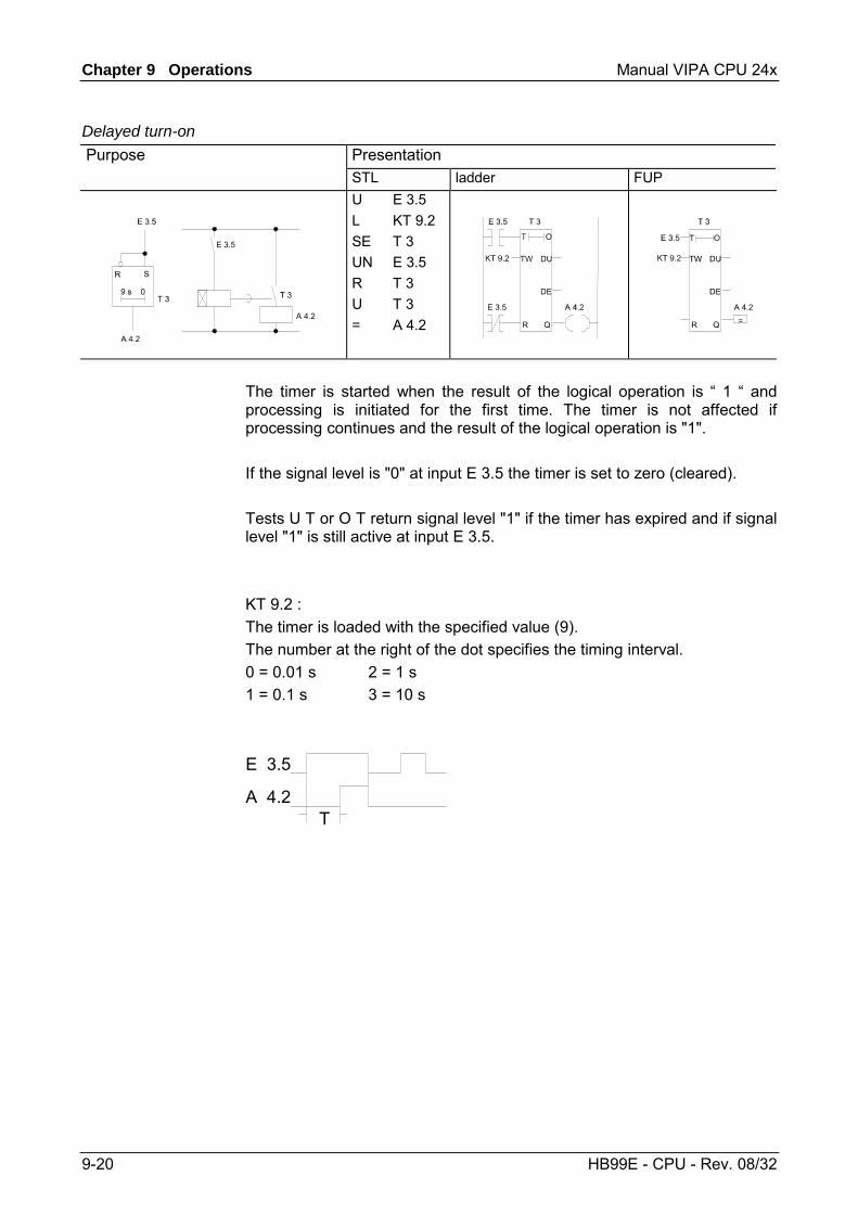
Chapter 9 Operations Manual VIPA CPU 24x
9-20 HB99E - CPU - Rev. 08/32
Delayed turn-on Purpose Presentation STL ladder FUP
U L SE UN R U =
E 3.5 KT 9.2 T 3 E 3.5 T 3 T 3 A 4.2
The timer is started when the result of the logical operation is “ 1 “ and processing is initiated for the first time. The timer is not affected if processing continues and the result of the logical operation is "1". If the signal level is "0" at input E 3.5 the timer is set to zero (cleared). Tests U T or O T return signal level "1" if the timer has expired and if signal level "1" is still active at input E 3.5. KT 9.2 : The timer is loaded with the specified value (9). The number at the right of the dot specifies the timing interval. 0 = 0.01 s 2 = 1 s 1 = 0.1 s 3 = 10 s E 3.5
A 4.2T
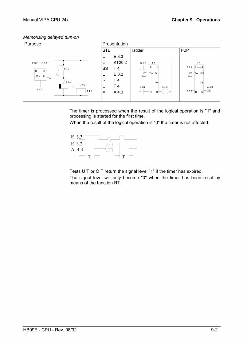
Manual VIPA CPU 24x Chapter 9 Operations
HB99E - CPU - Rev. 08/32 9-21
Memorizing delayed turn-on Purpose Presentation STL ladder FUP
A 4.3
E 3.3
T 4
SR
20 s 0
E 3.3
A 4.3
T 4
E 3.2
T 4
E 3.2
U L SS U R U =
E 3.3 KT20.2 T 4 E 3.2 T 4 T 4 A 4.3
The timer is processed when the result of the logical operation is "1" and processing is started for the first time. When the result of the logical operation is "0" the timer is not affected.
Tests U T or O T return the signal level "1" if the timer has expired. The signal level will only become "0" when the timer has been reset by means of the function RT.
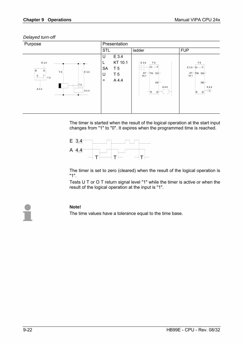
Chapter 9 Operations Manual VIPA CPU 24x
9-22 HB99E - CPU - Rev. 08/32
Delayed turn-off Purpose Presentation STL ladder FUP
U L SA U =
E 3.4 KT 10.1 T 5 T 5 A 4.4
The timer is started when the result of the logical operation at the start input changes from "1" to "0". It expires when the programmed time is reached. E 3.4
A 4.4T TT
The timer is set to zero (cleared) when the result of the logical operation is "1". Tests U T or O T return signal level "1" while the timer is active or when the result of the logical operation at the input is "1".
Note! The time values have a tolerance equal to the time base.
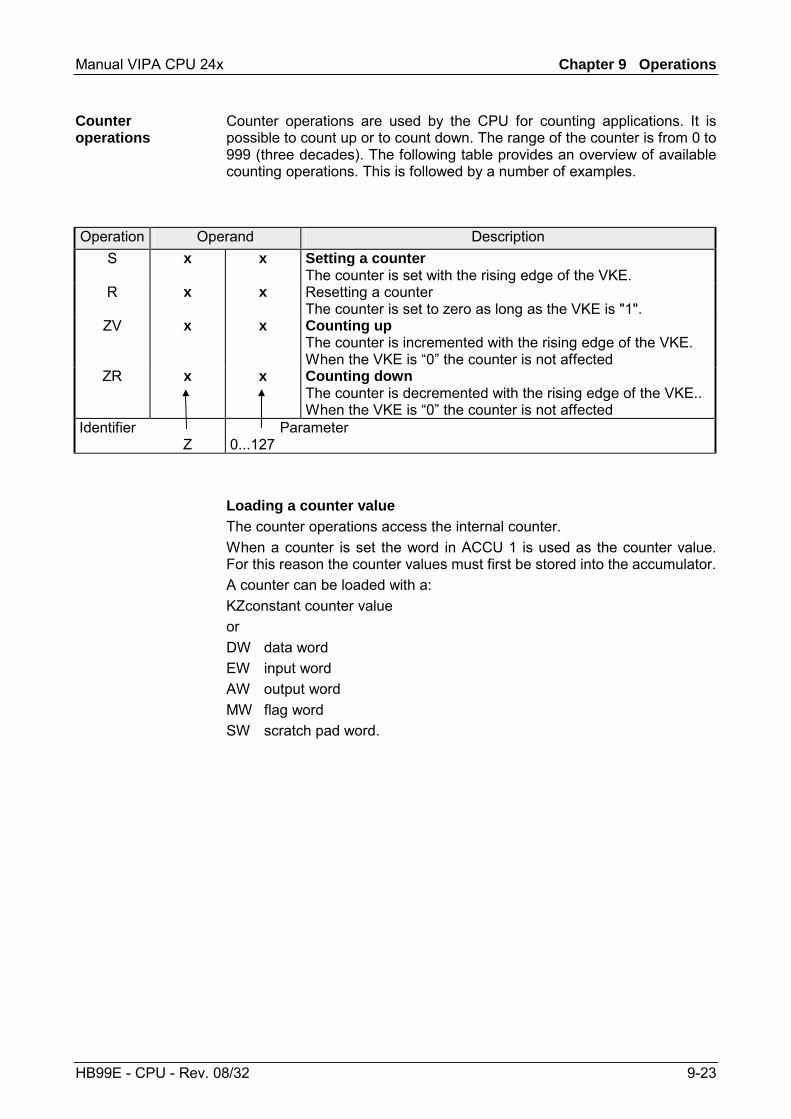
Manual VIPA CPU 24x Chapter 9 Operations
HB99E - CPU - Rev. 08/32 9-23
Counter operations are used by the CPU for counting applications. It is possible to count up or to count down. The range of the counter is from 0 to 999 (three decades). The following table provides an overview of available counting operations. This is followed by a number of examples.
Operation Operand Description S x x Setting a counter
The counter is set with the rising edge of the VKE. R x x Resetting a counter
The counter is set to zero as long as the VKE is "1". ZV x x Counting up
The counter is incremented with the rising edge of the VKE. When the VKE is “0” the counter is not affected
ZR x x Counting down The counter is decremented with the rising edge of the VKE.. When the VKE is “0” the counter is not affected
Identifier Z
Parameter 0...127
Loading a counter value The counter operations access the internal counter. When a counter is set the word in ACCU 1 is used as the counter value. For this reason the counter values must first be stored into the accumulator. A counter can be loaded with a: KZ constant counter value or DW data word EW input word AW output word MW flag word SW scratch pad word.
Counter operations
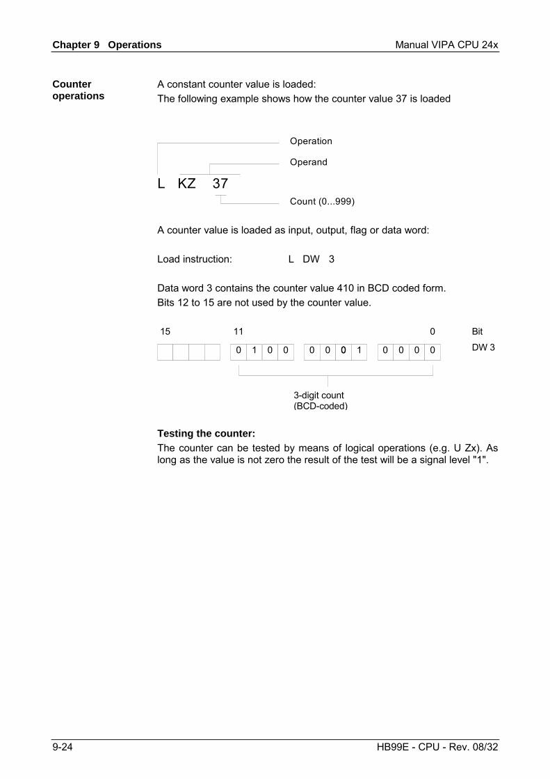
Chapter 9 Operations Manual VIPA CPU 24x
9-24 HB99E - CPU - Rev. 08/32
A constant counter value is loaded: The following example shows how the counter value 37 is loaded
L KZ 37
Operation
Operand
Count (0...999) A counter value is loaded as input, output, flag or data word: Load instruction: L DW 3 Data word 3 contains the counter value 410 in BCD coded form. Bits 12 to 15 are not used by the counter value.
10 0 0 0 0 0 0
3-digit count(BCD-coded)
01115 Bit
DW 30 00 01
Testing the counter: The counter can be tested by means of logical operations (e.g. U Zx). As long as the value is not zero the result of the test will be a signal level "1".
Counter operations
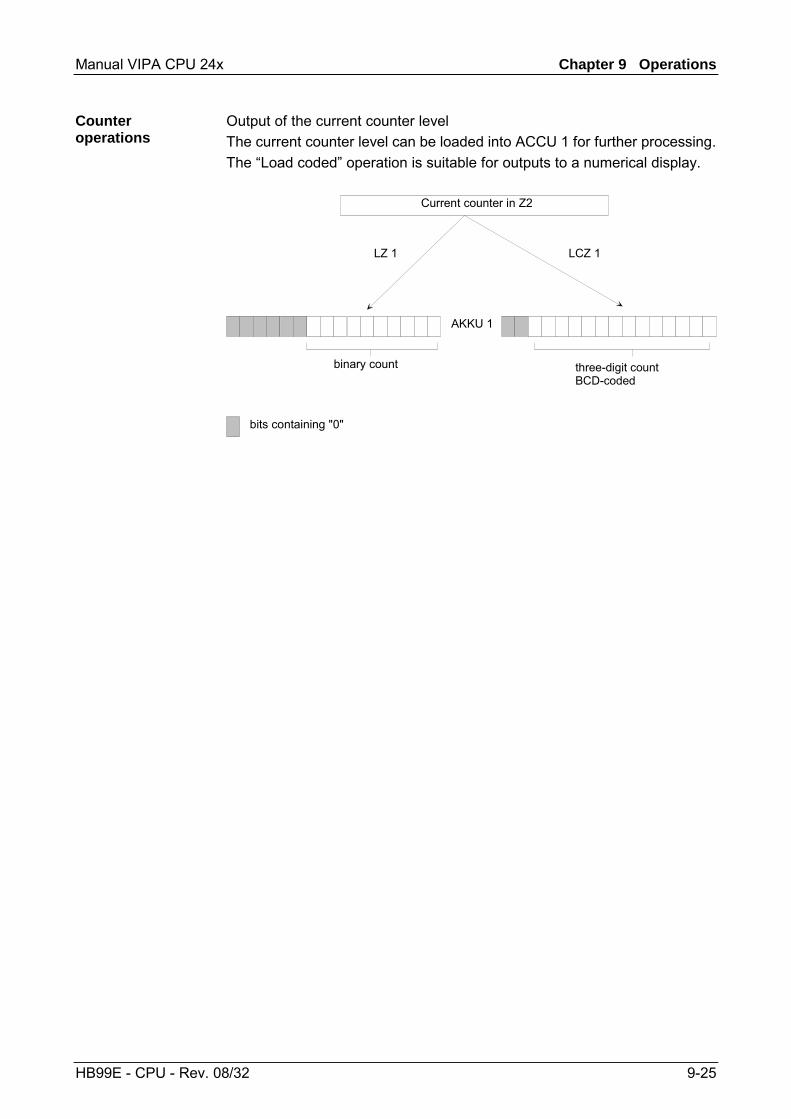
Manual VIPA CPU 24x Chapter 9 Operations
HB99E - CPU - Rev. 08/32 9-25
Output of the current counter level The current counter level can be loaded into ACCU 1 for further processing. The “Load coded” operation is suitable for outputs to a numerical display.
Current counter in Z2
LZ 1 LCZ 1
binary count three-digit countBCD-coded
bits containing "0"
AKKU 1
Counter operations

Chapter 9 Operations Manual VIPA CPU 24x
9-26 HB99E - CPU - Rev. 08/32
Setting a counter "S" and a down counter "ZR"
Setting a counter Purpose Presentation STL ladder FUP
U ZV U L S
E 4.0 Z 1 E 4.1 KZ 150 Z 1
The specified value (150) is loaded into the counter when the result of the logical operation at the start input (E 4.1) changes from "0" to "1". The flag that is required for the edge test of the set-input is included in the counter word. DU and DE are the digital outputs of the counter cell. Output DU provides the binary coded counter value and output DE the BCD-coded value.
Resetting a counter Purpose Presentation STL ladder FUP
U ZR U R U =
E 4.0 Z 2 E 4.2 Z 2 Z 2 A 2.4
The counter is set to zero (reset) when the result of the logical operation is "1" (E 4.2). The counter is not affected if the result of the logical operation is "0".
Counter operations
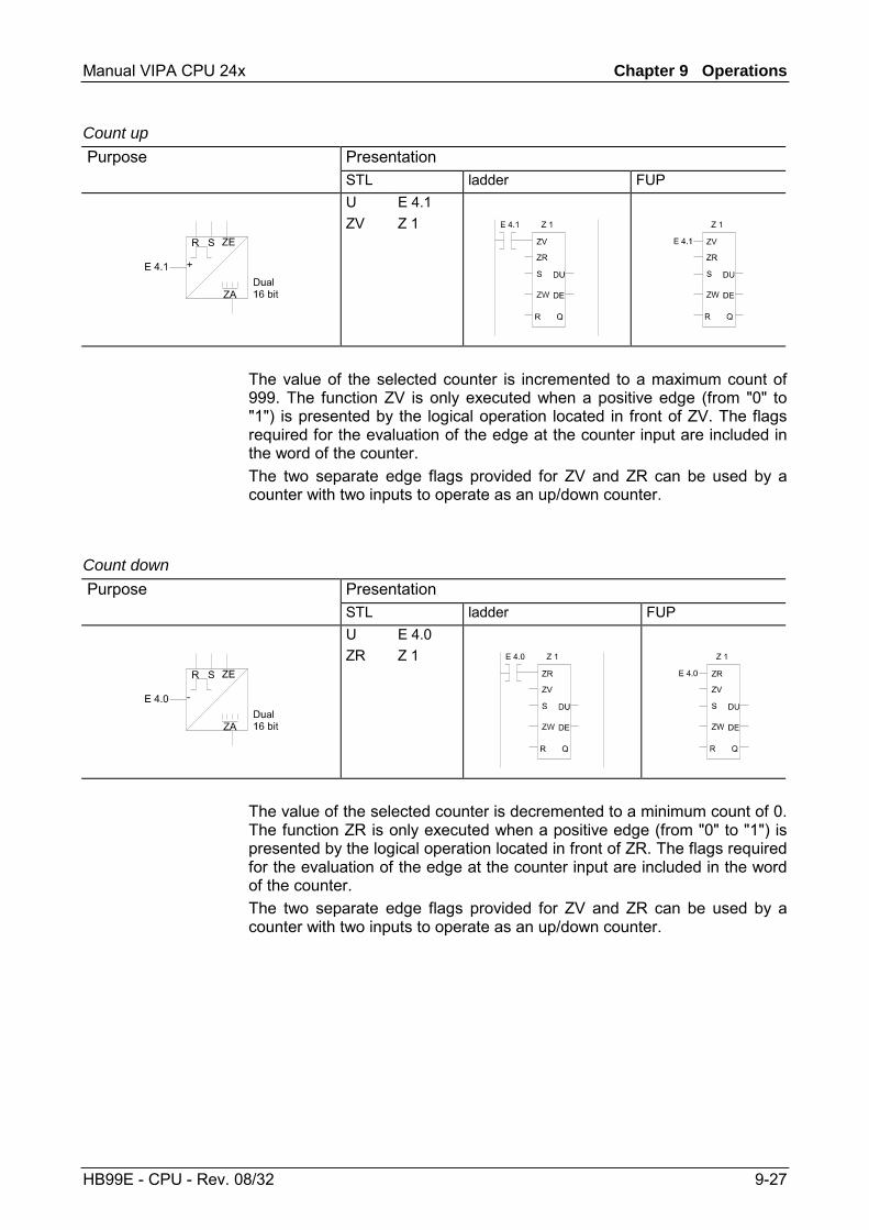
Manual VIPA CPU 24x Chapter 9 Operations
HB99E - CPU - Rev. 08/32 9-27
Count up Purpose Presentation STL ladder FUP
U ZV
E 4.1 Z 1
The value of the selected counter is incremented to a maximum count of 999. The function ZV is only executed when a positive edge (from "0" to "1") is presented by the logical operation located in front of ZV. The flags required for the evaluation of the edge at the counter input are included in the word of the counter. The two separate edge flags provided for ZV and ZR can be used by a counter with two inputs to operate as an up/down counter.
Count down Purpose Presentation STL ladder FUP
U ZR
E 4.0 Z 1
The value of the selected counter is decremented to a minimum count of 0. The function ZR is only executed when a positive edge (from "0" to "1") is presented by the logical operation located in front of ZR. The flags required for the evaluation of the edge at the counter input are included in the word of the counter. The two separate edge flags provided for ZV and ZR can be used by a counter with two inputs to operate as an up/down counter.
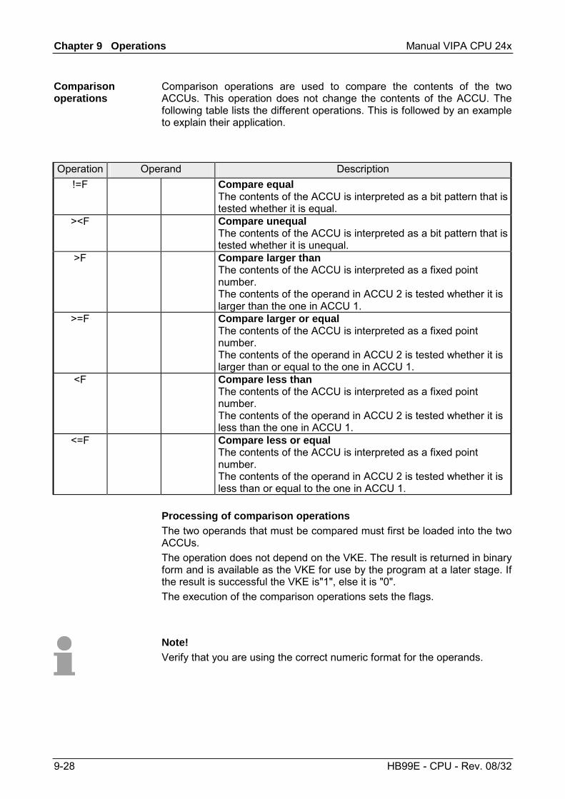
Chapter 9 Operations Manual VIPA CPU 24x
9-28 HB99E - CPU - Rev. 08/32
Comparison operations are used to compare the contents of the two ACCUs. This operation does not change the contents of the ACCU. The following table lists the different operations. This is followed by an example to explain their application.
Operation Operand Description !=F Compare equal
The contents of the ACCU is interpreted as a bit pattern that is tested whether it is equal.
><F Compare unequal The contents of the ACCU is interpreted as a bit pattern that is tested whether it is unequal.
>F Compare larger than The contents of the ACCU is interpreted as a fixed point number. The contents of the operand in ACCU 2 is tested whether it is larger than the one in ACCU 1.
>=F Compare larger or equal The contents of the ACCU is interpreted as a fixed point number. The contents of the operand in ACCU 2 is tested whether it is larger than or equal to the one in ACCU 1.
<F Compare less than The contents of the ACCU is interpreted as a fixed point number. The contents of the operand in ACCU 2 is tested whether it is less than the one in ACCU 1.
<=F Compare less or equal The contents of the ACCU is interpreted as a fixed point number. The contents of the operand in ACCU 2 is tested whether it is less than or equal to the one in ACCU 1.
Processing of comparison operations The two operands that must be compared must first be loaded into the two ACCUs. The operation does not depend on the VKE. The result is returned in binary form and is available as the VKE for use by the program at a later stage. If the result is successful the VKE is"1", else it is "0". The execution of the comparison operations sets the flags.
Note! Verify that you are using the correct numeric format for the operands.
Comparison operations

Manual VIPA CPU 24x Chapter 9 Operations
HB99E - CPU - Rev. 08/32 9-29
Example:
Compare equal Purpose Presentation STL ladder FUP
L L ! =
EB 19 EB 20 = F A 3.0
The first operand is compared to the following operand as specified by the comparison function. The comparison returns a binary result. VKE = "1": comparison is true if ACCU-1 is equal to ACCU-2. VKE = "0": comparison is false if ACCU-1 is not equal to ACCU-2. Indicators ANZ 1 and ANZ 0 are set as described in the operation. During the comparison the numeric representation of the operands is taken into account, i.e. in this case the contents of ACCU-1 and ACCU-2 are interpreted as fixed point number.
Comparison operations
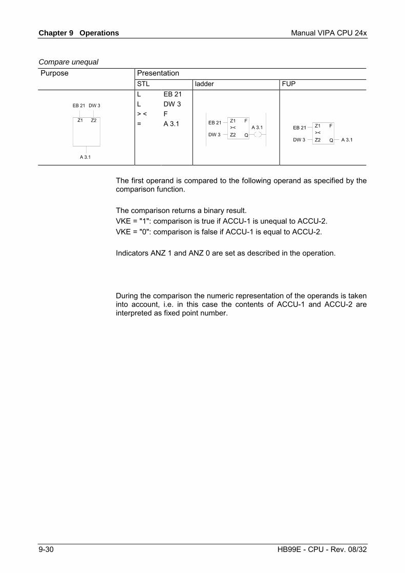
Chapter 9 Operations Manual VIPA CPU 24x
9-30 HB99E - CPU - Rev. 08/32
Compare unequal Purpose Presentation STL ladder FUP
L L > < =
EB 21 DW 3 F A 3.1
The first operand is compared to the following operand as specified by the comparison function. The comparison returns a binary result. VKE = "1": comparison is true if ACCU-1 is unequal to ACCU-2. VKE = "0": comparison is false if ACCU-1 is equal to ACCU-2. Indicators ANZ 1 and ANZ 0 are set as described in the operation. During the comparison the numeric representation of the operands is taken into account, i.e. in this case the contents of ACCU-1 and ACCU-2 are interpreted as fixed point number.
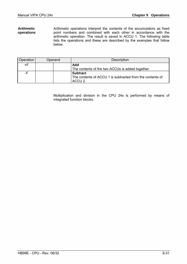
Manual VIPA CPU 24x Chapter 9 Operations
HB99E - CPU - Rev. 08/32 9-31
Arithmetic operations interpret the contents of the accumulators as fixed point numbers and combined with each other in accordance with the arithmetic operation. The result is saved in ACCU 1. The following table lists the operations and these are described by the examples that follow below.
Operation Operand Description +F Add
The contents of the two ACCUs is added together. -F Subtract
The contents of ACCU 1 is subtracted from the contents of ACCU 2.
Multiplication and division in the CPU 24x is performed by means of integrated function blocks.
Arithmetic operations
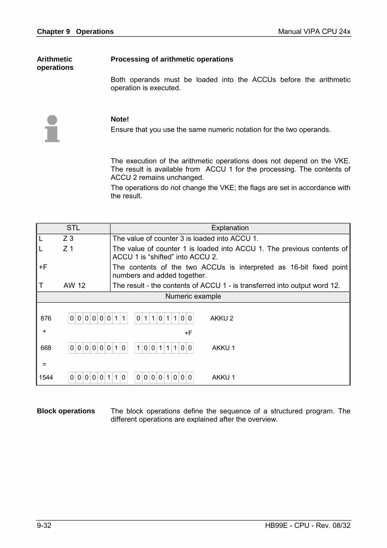
Chapter 9 Operations Manual VIPA CPU 24x
9-32 HB99E - CPU - Rev. 08/32
Processing of arithmetic operations Both operands must be loaded into the ACCUs before the arithmetic operation is executed.
Note! Ensure that you use the same numeric notation for the two operands.
The execution of the arithmetic operations does not depend on the VKE. The result is available from ACCU 1 for the processing. The contents of ACCU 2 remains unchanged. The operations do not change the VKE; the flags are set in accordance with the result.
STL Explanation L Z 3 The value of counter 3 is loaded into ACCU 1. L Z 1 The value of counter 1 is loaded into ACCU 1. The previous contents of
ACCU 1 is “shifted” into ACCU 2. +F The contents of the two ACCUs is interpreted as 16-bit fixed point
numbers and added together. T AW 12 The result - the contents of ACCU 1 - is transferred into output word 12.
Numeric example
0 0 0 0 0 0 0 0 0 0
00000000000
0 0 0 0 0 0 0 0 0 0 0 0 0
1 1 1 1 1 1
1 1 1 1 1
1 1 1
876
+
668
=
1544
+F
AKKU 2
AKKU 1
AKKU 1
The block operations define the sequence of a structured program. The different operations are explained after the overview.
Arithmetic operations
Block operations

Manual VIPA CPU 24x Chapter 9 Operations
HB99E - CPU - Rev. 08/32 9-33
Operation Operand Description SPA x x Absolute jump
Program execution continues in another component, independent of the status of the VKE. The VKE is not changed.
SPB x x Conditional jump In the case of VKE "1" the destination is another block. Otherwise processing is continues in the current block. In this case the VKE is set to "1"
Identifier OB PB FB SB
Parameter 0...255* 0...255 0...255 0...255
A x x Call to a data block A data block is activated, independent of the status of the VKE. Program execution is not interrupted. The VKE is not changed.
E x x Creating and erasing a data block** An area of RAM is prepared for the storage of, independent of the status of the VKE..
Identifier DB
Parameter 2...255***
BE Block end The current block is terminated, independent of the status of the VKE. Program execution continues in the block that issued the call. The VKE is ”transferred" but it is not changed.
BEA Absolute block end The current block is terminated, independent of the status of the VKE. Program execution continues in the block that issued the call. The VKE is ”transferred" but it is not changed.
BEB Conditional block end The current block is ended if VKE is "1". Program execution continues in the block that issued the call. VKE "1" is not changed when the block is changed. When the VKE is “0” the operation is not executed. The VKE is set to "1" and program execution is continued linearly.
* On the PG 615 you must select "System commands- Yes". You must also remember that certain OBs are occupied by the operating system.
** The length of the DB must be stored in ACCU 1 before the command is executed. If the length is 0 the DB is not valid.
*** Data blocks DB 0 and DB 1 are reserved.
Block operations
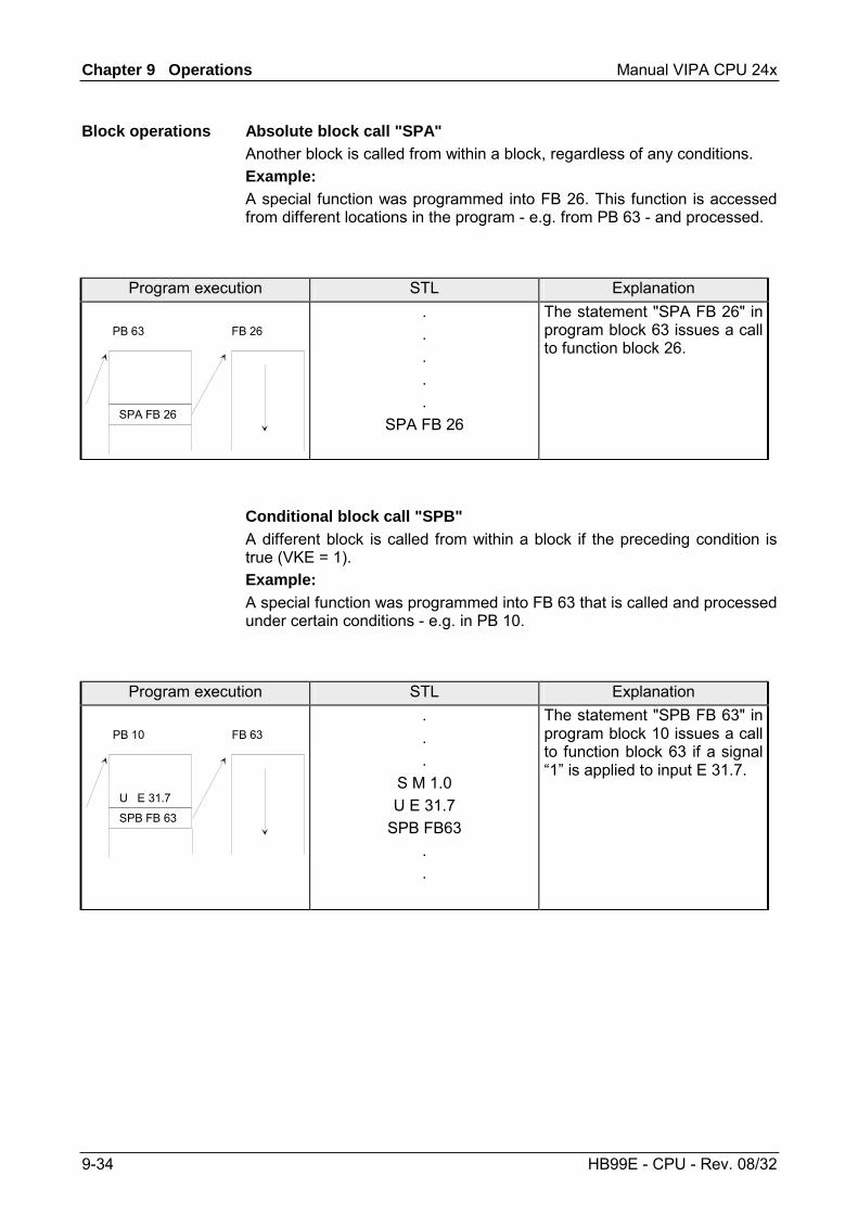
Chapter 9 Operations Manual VIPA CPU 24x
9-34 HB99E - CPU - Rev. 08/32
Absolute block call "SPA" Another block is called from within a block, regardless of any conditions. Example: A special function was programmed into FB 26. This function is accessed from different locations in the program - e.g. from PB 63 - and processed.
Program execution STL Explanation
PB 63 FB 26
SPA FB 26
.
.
.
.
. SPA FB 26
The statement "SPA FB 26" in program block 63 issues a call to function block 26.
Conditional block call "SPB" A different block is called from within a block if the preceding condition is true (VKE = 1). Example: A special function was programmed into FB 63 that is called and processed under certain conditions - e.g. in PB 10.
Program execution STL Explanation
PB 10 FB 63
SPB FB 63
U E 31.7
.
.
. S M 1.0 U E 31.7
SPB FB63 . .
The statement "SPB FB 63" in program block 10 issues a call to function block 63 if a signal “1” is applied to input E 31.7.
Block operations
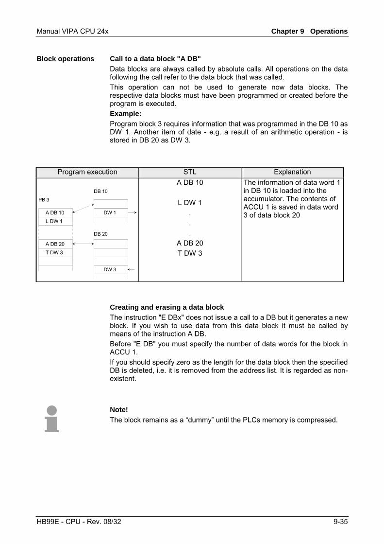
Manual VIPA CPU 24x Chapter 9 Operations
HB99E - CPU - Rev. 08/32 9-35
Call to a data block "A DB" Data blocks are always called by absolute calls. All operations on the data following the call refer to the data block that was called. This operation can not be used to generate now data blocks. The respective data blocks must have been programmed or created before the program is executed. Example: Program block 3 requires information that was programmed in the DB 10 as DW 1. Another item of date - e.g. a result of an arithmetic operation - is stored in DB 20 as DW 3.
Program execution STL Explanation
A DB 10L DW 1
A DB 20T DW 3
PB 3
DB 10
DW 1
DB 20
DW 3
A DB 10
L DW 1 . . .
A DB 20 T DW 3
The information of data word 1 in DB 10 is loaded into the accumulator. The contents of ACCU 1 is saved in data word 3 of data block 20
Creating and erasing a data block The instruction "E DBx" does not issue a call to a DB but it generates a new block. If you wish to use data from this data block it must be called by means of the instruction A DB. Before "E DB" you must specify the number of data words for the block in ACCU 1. If you should specify zero as the length for the data block then the specified DB is deleted, i.e. it is removed from the address list. It is regarded as non-existent.
Note! The block remains as a “dummy” until the PLCs memory is compressed.
Block operations
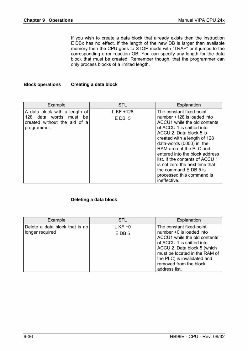
Chapter 9 Operations Manual VIPA CPU 24x
9-36 HB99E - CPU - Rev. 08/32
If you wish to create a data block that already exists then the instruction E DBx has no effect. If the length of the new DB is larger than available memory then the CPU goes to STOP mode with "TRAF" or it jumps to the corresponding error reaction OB. You can specify any length for the data block that must be created. Remember though, that the programmer can only process blocks of a limited length.
Creating a data block
Example STL Explanation A data block with a length of 128 data words must be created without the aid of a programmer.
L KF +128 E DB 5
The constant fixed-point number +128 is loaded into ACCU1 while the old contents of ACCU 1 is shifted into ACCU 2. Data block 5 is created with a length of 128 data-words (0000) in the RAM-area of the PLC and entered into the block address list. If the contents of ACCU 1 is not zero the next time that the command E DB 5 is processed this command is ineffective.
Deleting a data block
Example STL Explanation Delete a data block that is no longer required
L KF +0 E DB 5
The constant fixed-point number +0 is loaded into ACCU1 while the old contents of ACCU 1 is shifted into ACCU 2. Data block 5 (which must be located in the RAM of the PLC) is invalidated and removed from the block address list.
Block operations

Manual VIPA CPU 24x Chapter 9 Operations
HB99E - CPU - Rev. 08/32 9-37
Termination of a block "BE" The operation "BE" terminates a block; data blocks do not require termination. "BE" is always the last instruction of a block. In a structured program the program continues with the block that issued the call. Binary operations cannot be continued in the calling block. Example: Program block 3 is terminated by the "BE" instruction.
Program execution STL Explanation
OB 1 PB 3
SPA PB 3
BE
.
.
.
.
. BE
The "BE" instruction terminates PB 3 and causes a return to OB1.
Absolute return "BEA" The "BEA" operation causes a return within a block. In FBs it is possible, however, to bypass this instruction by means of a jump operation. Binary operations can not be continued in the calling block. Example: Processing of FB 21 is terminated regardless of the status of the VKS.
Program execution STL Explanation
OB 1 PB 3
SPA PB 3
BEA
SPB =
BE
.
.
.
. SPB= BEA
.
.
. BE
The "BEA" instruction is the reason that the program quits from FB 21. It is followed by a return to PB 8.
Block operations
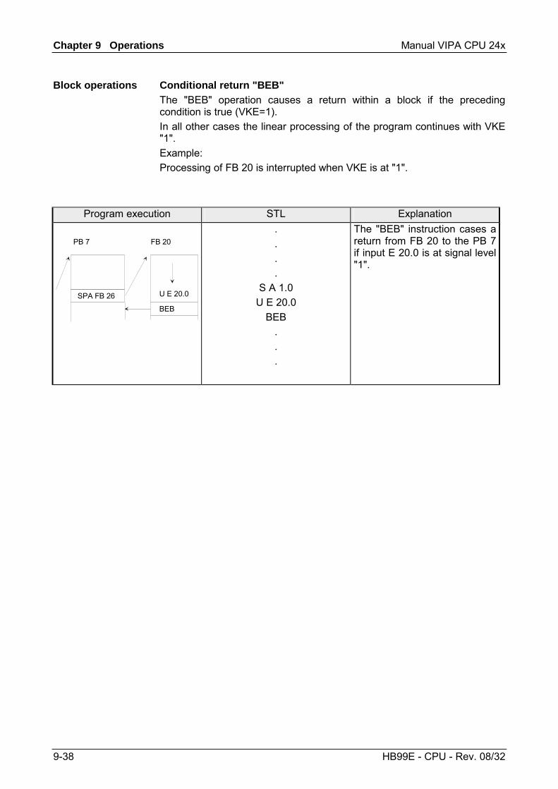
Chapter 9 Operations Manual VIPA CPU 24x
9-38 HB99E - CPU - Rev. 08/32
Conditional return "BEB" The "BEB" operation causes a return within a block if the preceding condition is true (VKE=1). In all other cases the linear processing of the program continues with VKE "1". Example: Processing of FB 20 is interrupted when VKE is at "1".
Program execution STL Explanation
PB 7 FB 20
SPA FB 26 U E 20.0
BEB
.
.
.
. S A 1.0
U E 20.0 BEB
.
.
.
The "BEB" instruction cases a return from FB 20 to the PB 7 if input E 20.0 is at signal level "1".
Block operations

Manual VIPA CPU 24x Chapter 9 Operations
HB99E - CPU - Rev. 08/32 9-39
The following table lists some additional primary operations followed by a description.
Operation Operand Description STP Stop at the end of the program
The execution of the current program is terminated; the PAA is returned. The PLC goes to STOP mode.
NOP 0 Null operation The respective 16 bits in RAM are set to "0".
NOP 1 Null operation The respective 16 bits in RAM are set to "1".
BLD x Image creation commands for the programmer
Identifier Parameter 130, 131, 132, 133, 255
Note! These operations can only be programmed as a STL.
The operation "STP" places the PLC in STOP mode. This may be necessary when the system is in a time-critical condition or when an equipment error occurs. When the instruction has been processed the control program is executed all the way up to the end of the program - ignoring the processing markers. At this point the PLC goes to STOP mode with an error flag "STS". It can be started again by means of the function selector (STOP→RUN) or via the PG. Null operation "NOP" or null operations reserve space in memory. Image creation operations The different routines of a program within a block are subdivided into segments by image creation operations "BLD". Null and image creation operations only apply to the representation of the program by the PG. No operations are executed by the CPU when these instructions are executed.
Other operations
STOP operation
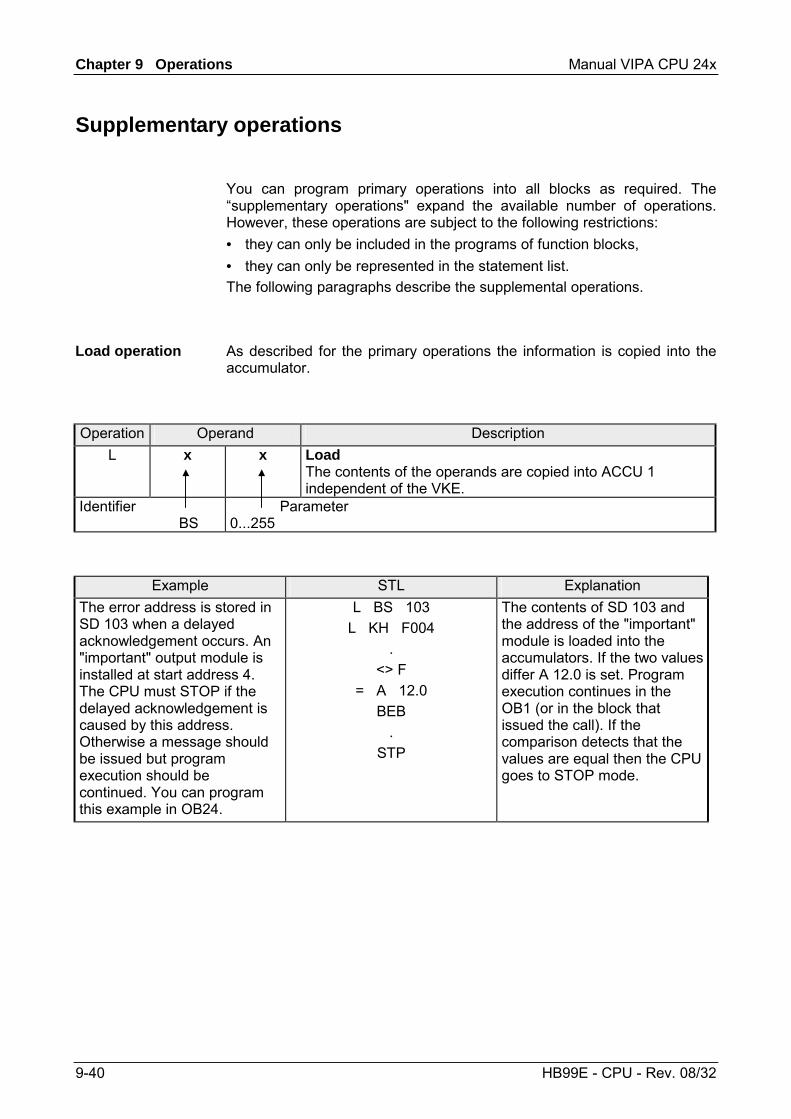
Chapter 9 Operations Manual VIPA CPU 24x
9-40 HB99E - CPU - Rev. 08/32
Supplementary operations
You can program primary operations into all blocks as required. The “supplementary operations" expand the available number of operations. However, these operations are subject to the following restrictions: • they can only be included in the programs of function blocks, • they can only be represented in the statement list. The following paragraphs describe the supplemental operations.
As described for the primary operations the information is copied into the accumulator.
Operation Operand Description L x x Load
The contents of the operands are copied into ACCU 1 independent of the VKE.
Identifier BS
Parameter 0...255
Example STL Explanation The error address is stored in SD 103 when a delayed acknowledgement occurs. An "important" output module is installed at start address 4. The CPU must STOP if the delayed acknowledgement is caused by this address. Otherwise a message should be issued but program execution should be continued. You can program this example in OB24.
L BS 103 L KH F004
. <> F
= A 12.0 BEB
. STP
The contents of SD 103 and the address of the "important" module is loaded into the accumulators. If the two values differ A 12.0 is set. Program execution continues in the OB1 (or in the block that issued the call). If the comparison detects that the values are equal then the CPU goes to STOP mode.
Load operation

Manual VIPA CPU 24x Chapter 9 Operations
HB99E - CPU - Rev. 08/32 9-41
The release operation "FR" is used to execute the following operations without an edge transition: • starting a timer • setting a counter • up and down counts.
Operation Operand Description FR x x Releasing a timer/ a counter
With the rising edge of the VKE the timers and counters are released. The operation results in the restart of a timer, the setting, up or down count of a counter if VKE "1" is active at the "start-operation.
Identifier T Z
Parameter 0...127 0...127
Example STL Explanation Timer T 2 is started as an extended impulse by E 2.5 (pulse width 50s). This time sets A 4.2 for the duration of the pulse. If A 3.4 is set repeatedly then the timer must be started over and over again
U E 2.5 L KT 50.2
SV T 2 U T 2
= A 4.2 . . . .
U A 3.4 FR T 2
. BE
Start of timer T2 as extended pulse. Output 4.2 is set for 50s. If output 3.4 is set during the time (positive edge transition of the VKE) that input 2.5 is set then timer T2 is started again. This means that the A 4.2 remains set for the time that was restarted or it is set again.The timer is not restarted if E 2.5 was not set when the edge transition of A 3.4 occurred then.
Release operation
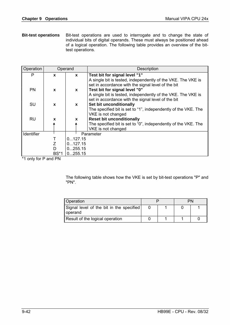
Chapter 9 Operations Manual VIPA CPU 24x
9-42 HB99E - CPU - Rev. 08/32
Bit-test operations are used to interrogate and to change the state of individual bits of digital operands. These must always be positioned ahead of a logical operation. The following table provides an overview of the bit-test operations.
Operation Operand Description P x x Test bit for signal level "1"
A single bit is tested, independently of the VKE. The VKE is set in accordance with the signal level of the bit
PN x x Test bit for signal level "0" A single bit is tested, independently of the VKE. The VKE is set in accordance with the signal level of the bit
SU x x Set bit unconditionally The specified bit is set to “1”, independently of the VKE. The VKE is not changed
RU x x Reset bit unconditionally The specified bit is set to “0”, independently of the VKE. The VKE is not changed
Identifier T Z D BS*1
Parameter 0...127.15 0...127.15 0...255.15 0...255.15
*1 only for P and PN
The following table shows how the VKE is set by bit-test operations "P" and "PN".
Operation P PN Signal level of the bit in the specified operand
0 1 0 1
Result of the logical operation 0 1 1 0
Bit-test operations
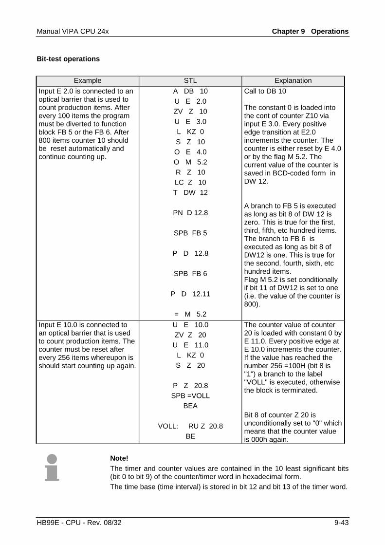
Manual VIPA CPU 24x Chapter 9 Operations
HB99E - CPU - Rev. 08/32 9-43
Example STL Explanation Input E 2.0 is connected to an optical barrier that is used to count production items. After every 100 items the program must be diverted to function block FB 5 or the FB 6. After 800 items counter 10 should be reset automatically and continue counting up.
A DB 10 U E 2.0 ZV Z 10 U E 3.0 L KZ 0 S Z 10 O E 4.0 O M 5.2 R Z 10 LC Z 10 T DW 12
PN D 12.8
SPB FB 5
P D 12.8
SPB FB 6
P D 12.11
= M 5.2
Call to DB 10 The constant 0 is loaded into the cont of counter Z10 via input E 3.0. Every positive edge transition at E2.0 increments the counter. The counter is either reset by E 4.0 or by the flag M 5.2. The current value of the counter is saved in BCD-coded form in DW 12. A branch to FB 5 is executed as long as bit 8 of DW 12 is zero. This is true for the first, third, fifth, etc hundred items. The branch to FB 6 is executed as long as bit 8 of DW12 is one. This is true for the second, fourth, sixth, etc hundred items. Flag M 5.2 is set conditionally if bit 11 of DW12 is set to one (i.e. the value of the counter is 800).
Input E 10.0 is connected to an optical barrier that is used to count production items. The counter must be reset after every 256 items whereupon is should start counting up again.
U E 10.0 ZV Z 20
U E 11.0 L KZ 0 S Z 20
P Z 20.8 SPB =VOLL
BEA
VOLL: RU Z 20.8 BE
The counter value of counter 20 is loaded with constant 0 by E 11.0. Every positive edge at E 10.0 increments the counter. If the value has reached the number 256 =100H (bit 8 is "1") a branch to the label "VOLL" is executed, otherwise the block is terminated. Bit 8 of counter Z 20 is unconditionally set to "0" which means that the counter value is 000h again.
Note! The timer and counter values are contained in the 10 least significant bits (bit 0 to bit 9) of the counter/timer word in hexadecimal form. The time base (time interval) is stored in bit 12 and bit 13 of the timer word.
Bit-test operations
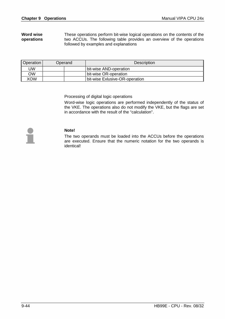
Chapter 9 Operations Manual VIPA CPU 24x
9-44 HB99E - CPU - Rev. 08/32
These operations perform bit-wise logical operations on the contents of the two ACCUs. The following table provides an overview of the operations followed by examples and explanations
Operation Operand Description UW bit-wise AND-operation OW bit-wise OR-operation
XOW bit-wise Exlusive-OR-operation
Processing of digital logic operations Word-wise logic operations are performed independently of the status of the VKE. The operations also do not modify the VKE, but the flags are set in accordance with the result of the “calculation".
Note! The two operands must be loaded into the ACCUs before the operations are executed. Ensure that the numeric notation for the two operands is identical!
Word wise operations
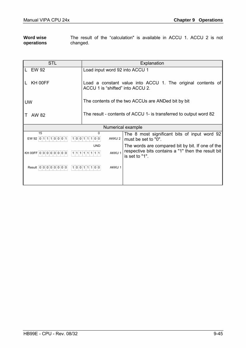
Manual VIPA CPU 24x Chapter 9 Operations
HB99E - CPU - Rev. 08/32 9-45
The result of the “calculation" is available in ACCU 1. ACCU 2 is not changed.
STL Explanation L EW 92 L KH 00FF UW T AW 82
Load input word 92 into ACCU 1 Load a constant value into ACCU 1. The original contents of ACCU 1 is “shifted” into ACCU 2. The contents of the two ACCUs are ANDed bit by bit The result - contents of ACCU 1- is transferred to output word 82
Numerical example
0 0 0 0 0
0000000
0 0 0 0 0 0 0 0 0 0
1 1 1
1 1 1 1
1
UND
AKKU 2
AKKU 1
AKKU 1
10010111
0 1 1 1 1
00 111
015
EW 92
KH 00FF
Result
The 8 most significant bits of input word 92 must be set to "0". The words are compared bit by bit. If one of the respective bits contains a "1" then the result bit is set to "1".
Word wise operations
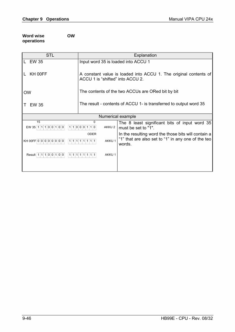
Chapter 9 Operations Manual VIPA CPU 24x
9-46 HB99E - CPU - Rev. 08/32
OW
STL Explanation L EW 35 L KH 00FF OW T EW 35
Input word 35 is loaded into ACCU 1 A constant value is loaded into ACCU 1. The original contents of ACCU 1 is “shifted” into ACCU 2. The contents of the two ACCUs are ORed bit by bit The result - contents of ACCU 1- is transferred to output word 35
Numerical example
0 0
0000000
0 0 0
1
1 1 1 1
1
ODER
AKKU 2
AKKU 1
AKKU 1
01011
0 1 1 1 1
0 111
015
1001001 1
1 1 1 11111
EW 35
KH 00FF
Result
The 8 least significant bits of input word 35 must be set to "1". In the resulting word the those bits will contain a “1” that are also set to “1” in any one of the teo words.
Word wise operations
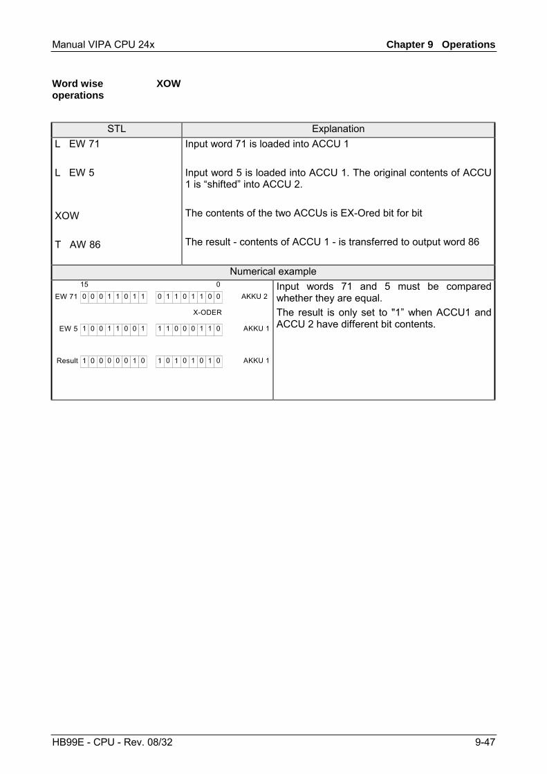
Manual VIPA CPU 24x Chapter 9 Operations
HB99E - CPU - Rev. 08/32 9-47
XOW
STL Explanation L EW 71 L EW 5 XOW T AW 86
Input word 71 is loaded into ACCU 1 Input word 5 is loaded into ACCU 1. The original contents of ACCU 1 is “shifted” into ACCU 2. The contents of the two ACCUs is EX-Ored bit for bit The result - contents of ACCU 1 - is transferred to output word 86
Numerical example
0
000
0 0 0
1
1 1
1
X-ODER
AKKU 2
AKKU 1
AKKU 1
0 1 1
1
015
01
1 1
EW 71
EW 5
Result
000000 111111
00001111
0 0 0 010001
Input words 71 and 5 must be compared whether they are equal. The result is only set to "1” when ACCU1 and ACCU 2 have different bit contents.
Word wise operations

Chapter 9 Operations Manual VIPA CPU 24x
9-48 HB99E - CPU - Rev. 08/32
These operations shift the bit-pattern in ACCU 1; the contents of ACCU2 is not changed. The shift results in a multiplication or a division of the contents of ACCU1 by a power of 2.
Operation Operand Description SLW x Left shift
The bit-pattern in ACCU 1 is shifted left SRW x Right shift
The bit-pattern in ACCU1 shifted right Parameter
0...15
Processing of a shift operation The execution of the shift operation does not depend on any conditions. The VKE is not changed. However, the flags are set by the shift operation. The status of the bit that was the last one to be shifted out and it can therefore be tested by conditional jump functions. The parameter of the instruction specifies the number of bit positions by which the contents of ACCU 1 must be shifted left (SLW) or shifted right (SRW). The bit positions that are cleared by the shift operation are set to zero. Bits that are "shifted out" are discarded. The status of bit 20 (SRW) or of bit 215 (SLW) modifies the ANZ 1-bit after the command was executed. This bit can be tested. A shift operation with a parameter of "0" is treated like a null-operation (NOP). The central processing unit continues with the next instruction. Before the instruction is executed the operand that should be processed must be loaded into ACCU 1. Here the modified operand is available for further processing.
Shift operations
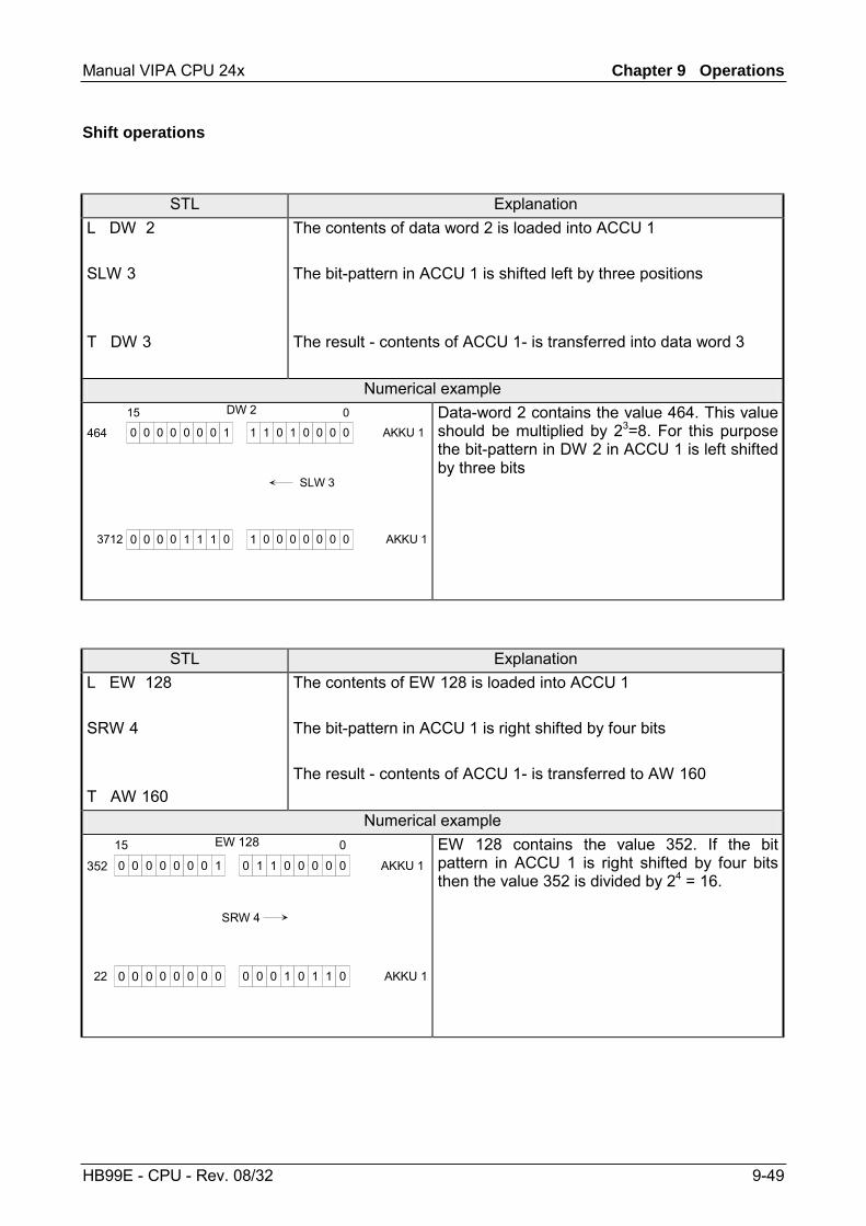
Manual VIPA CPU 24x Chapter 9 Operations
HB99E - CPU - Rev. 08/32 9-49
STL Explanation
L DW 2 SLW 3 T DW 3
The contents of data word 2 is loaded into ACCU 1 The bit-pattern in ACCU 1 is shifted left by three positions The result - contents of ACCU 1- is transferred into data word 3
Numerical example
0
0 0
AKKU 1
AKKU 11
015
1464 00000 1
0 0 0 0100
DW 2
3712
000000 1 1
000110
SLW 3
Data-word 2 contains the value 464. This value should be multiplied by 23=8. For this purpose the bit-pattern in DW 2 in ACCU 1 is left shifted by three bits
STL Explanation L EW 128 SRW 4 T AW 160
The contents of EW 128 is loaded into ACCU 1 The bit-pattern in ACCU 1 is right shifted by four bits The result - contents of ACCU 1- is transferred to AW 160
Numerical example
0
0 0
AKKU 1
AKKU 1
015
1352 00000 1
0 000
EW 128
22
00000
000
SRW 4
010
0 0 0 0 1 1 1
EW 128 contains the value 352. If the bit pattern in ACCU 1 is right shifted by four bits then the value 352 is divided by 24 = 16.
Shift operations
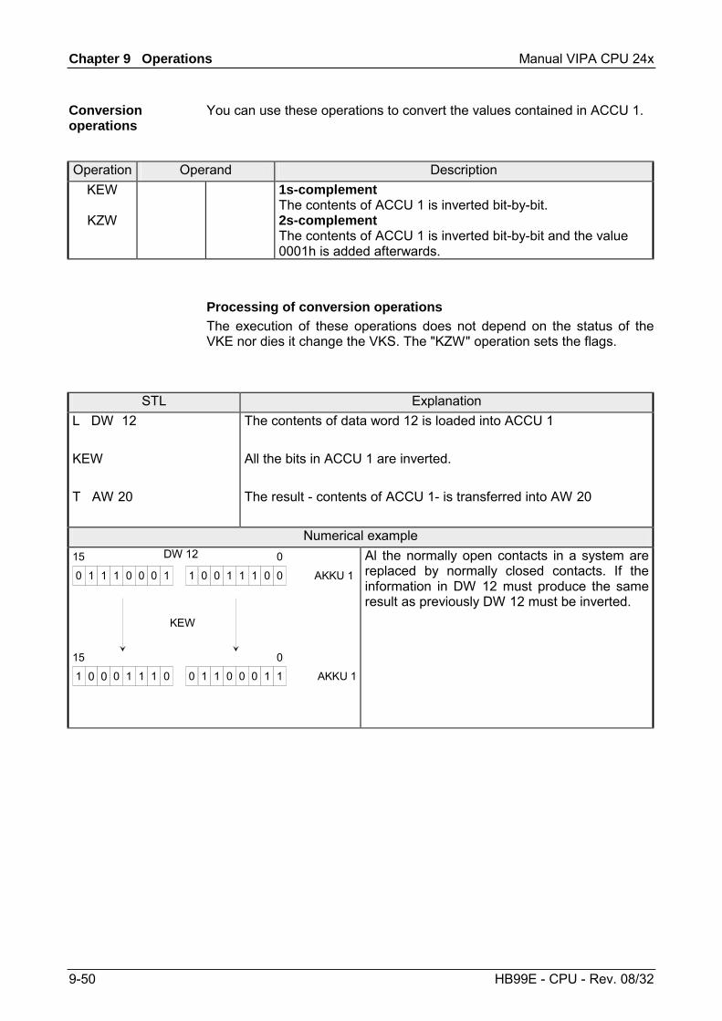
Chapter 9 Operations Manual VIPA CPU 24x
9-50 HB99E - CPU - Rev. 08/32
You can use these operations to convert the values contained in ACCU 1.
Operation Operand Description KEW 1s-complement
The contents of ACCU 1 is inverted bit-by-bit. KZW 2s-complement
The contents of ACCU 1 is inverted bit-by-bit and the value 0001h is added afterwards.
Processing of conversion operations The execution of these operations does not depend on the status of the VKE nor dies it change the VKS. The "KZW" operation sets the flags.
STL Explanation L DW 12 KEW T AW 20
The contents of data word 12 is loaded into ACCU 1 All the bits in ACCU 1 are inverted. The result - contents of ACCU 1- is transferred into AW 20
Numerical example
0
0 0
AKKU 1
AKKU 1
015
000 1
00
DW 12
00
0
KEW
0 1
1 1 1 11 1 1 0 0
1111111 0 0
015
Al the normally open contacts in a system are replaced by normally closed contacts. If the information in DW 12 must produce the same result as previously DW 12 must be inverted.
Conversion operations

Manual VIPA CPU 24x Chapter 9 Operations
HB99E - CPU - Rev. 08/32 9-51
STL Explanation
L EW 12 KZW T DW 100
The contents of EW12 is loaded into ACCU 1. All the bits in ACCU 1 are inverted, a “1” is added to the least significant bit. The modified word is transferred into DW 100.
Numerical example
0 0
AKKU 1
AKKU 1
015
000 1
0
EW 12
0
KZW
0 1
1 11 1 0
11111 0
015
00 1 1 10 0
+1
1 1 10 0
The value in EW 12 must be converted to a negative value.
Conversion operations
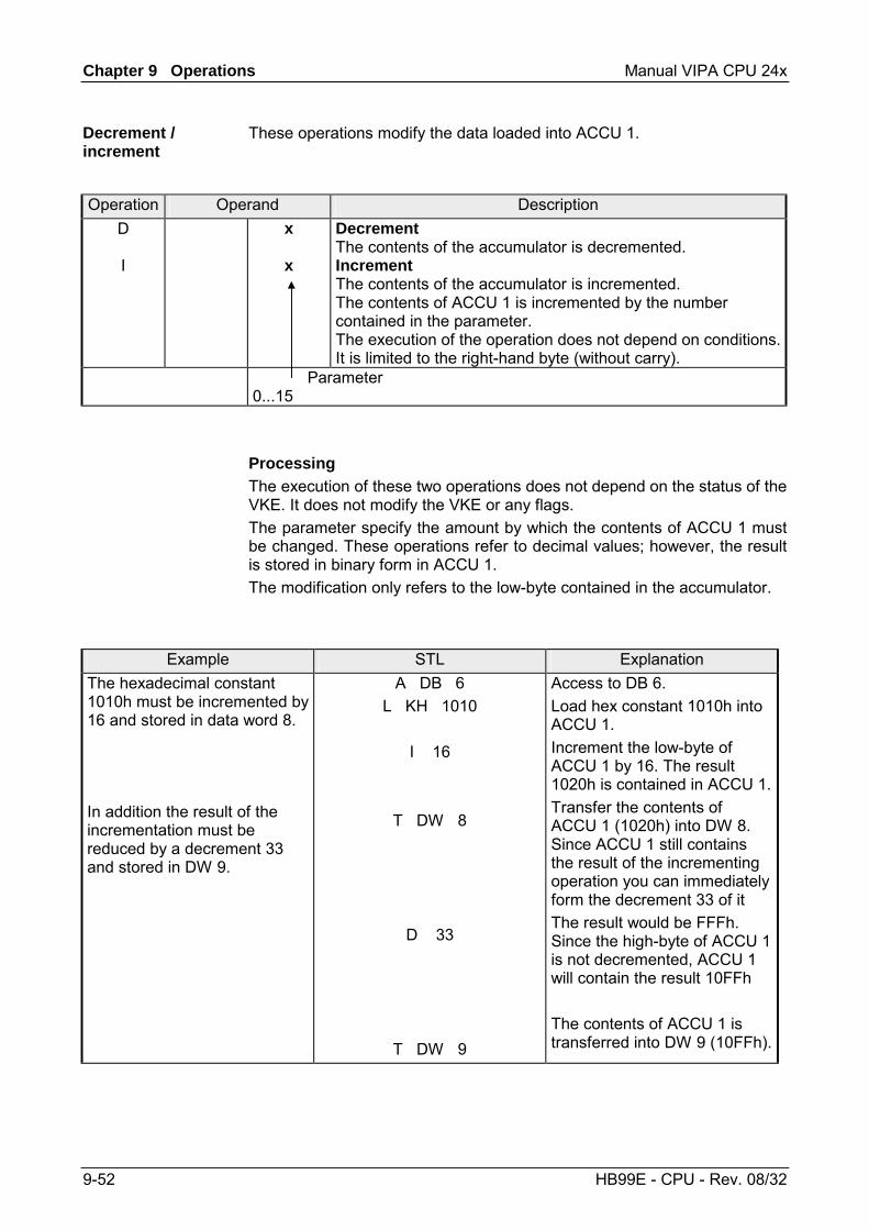
Chapter 9 Operations Manual VIPA CPU 24x
9-52 HB99E - CPU - Rev. 08/32
These operations modify the data loaded into ACCU 1.
Operation Operand Description D x Decrement
The contents of the accumulator is decremented. I x Increment
The contents of the accumulator is incremented. The contents of ACCU 1 is incremented by the number contained in the parameter. The execution of the operation does not depend on conditions. It is limited to the right-hand byte (without carry).
Parameter 0...15
Processing The execution of these two operations does not depend on the status of the VKE. It does not modify the VKE or any flags. The parameter specify the amount by which the contents of ACCU 1 must be changed. These operations refer to decimal values; however, the result is stored in binary form in ACCU 1. The modification only refers to the low-byte contained in the accumulator.
Example STL Explanation The hexadecimal constant 1010h must be incremented by 16 and stored in data word 8. In addition the result of the incrementation must be reduced by a decrement 33 and stored in DW 9.
A DB 6 L KH 1010
I 16
T DW 8
D 33
T DW 9
Access to DB 6. Load hex constant 1010h into ACCU 1. Increment the low-byte of ACCU 1 by 16. The result 1020h is contained in ACCU 1.Transfer the contents of ACCU 1 (1020h) into DW 8. Since ACCU 1 still contains the result of the incrementing operation you can immediately form the decrement 33 of it The result would be FFFh. Since the high-byte of ACCU 1 is not decremented, ACCU 1 will contain the result 10FFh The contents of ACCU 1 is transferred into DW 9 (10FFh).
Decrement / increment
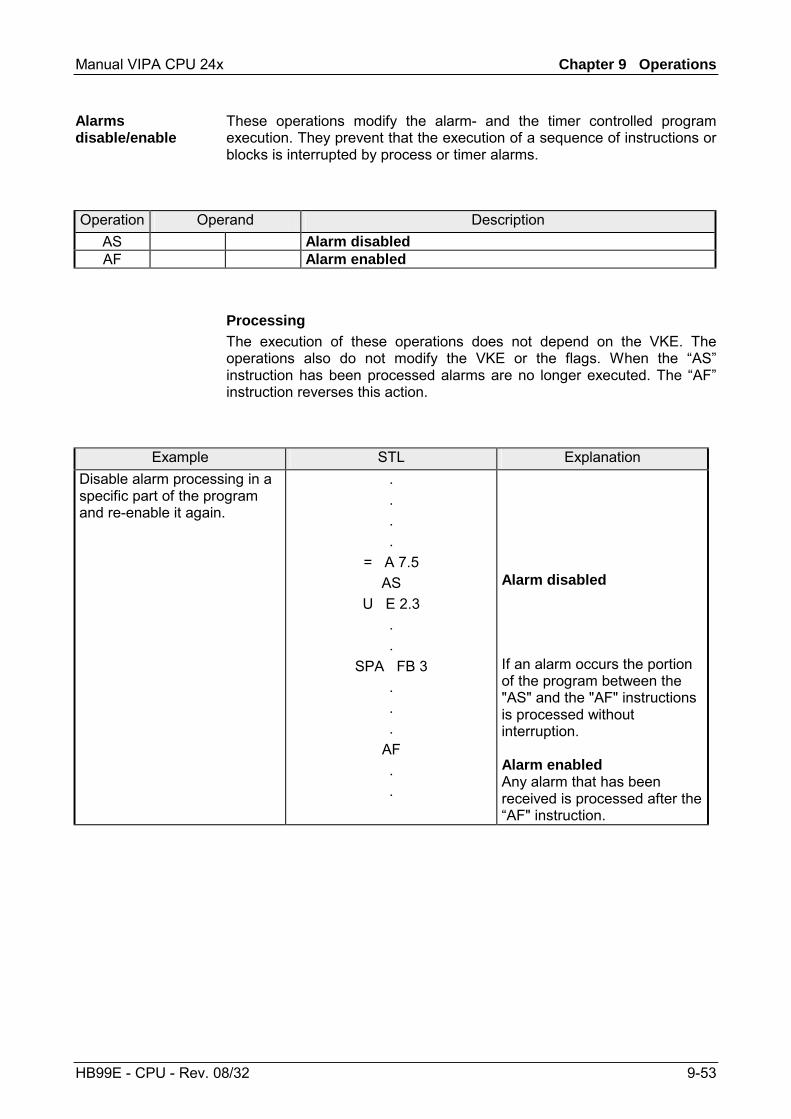
Manual VIPA CPU 24x Chapter 9 Operations
HB99E - CPU - Rev. 08/32 9-53
These operations modify the alarm- and the timer controlled program execution. They prevent that the execution of a sequence of instructions or blocks is interrupted by process or timer alarms.
Operation Operand Description AS Alarm disabled AF Alarm enabled
Processing The execution of these operations does not depend on the VKE. The operations also do not modify the VKE or the flags. When the “AS” instruction has been processed alarms are no longer executed. The “AF” instruction reverses this action.
Example STL Explanation Disable alarm processing in a specific part of the program and re-enable it again.
.
.
.
. = A 7.5
AS U E 2.3
.
. SPA FB 3
.
.
. AF . .
Alarm disabled If an alarm occurs the portion of the program between the "AS" and the "AF" instructions is processed without interruption. Alarm enabled Any alarm that has been received is processed after the “AF" instruction.
Alarms disable/enable
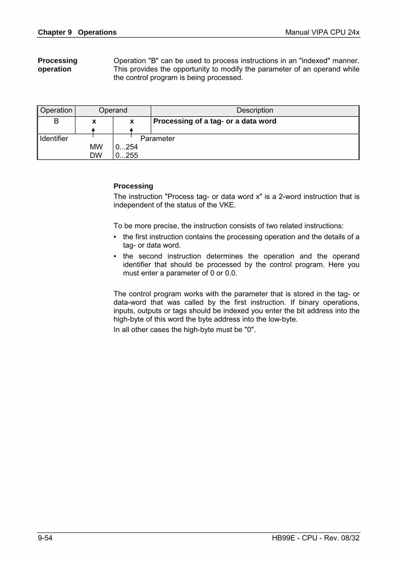
Chapter 9 Operations Manual VIPA CPU 24x
9-54 HB99E - CPU - Rev. 08/32
Operation "B" can be used to process instructions in an "indexed" manner. This provides the opportunity to modify the parameter of an operand while the control program is being processed.
Operation Operand Description B x x Processing of a tag- or a data word
Identifier MW DW
Parameter 0...254 0...255
Processing The instruction "Process tag- or data word x" is a 2-word instruction that is independent of the status of the VKE. To be more precise, the instruction consists of two related instructions: • the first instruction contains the processing operation and the details of a
tag- or data word. • the second instruction determines the operation and the operand
identifier that should be processed by the control program. Here you must enter a parameter of 0 or 0.0.
The control program works with the parameter that is stored in the tag- or data-word that was called by the first instruction. If binary operations, inputs, outputs or tags should be indexed you enter the bit address into the high-byte of this word the byte address into the low-byte. In all other cases the high-byte must be "0".
Processing operation
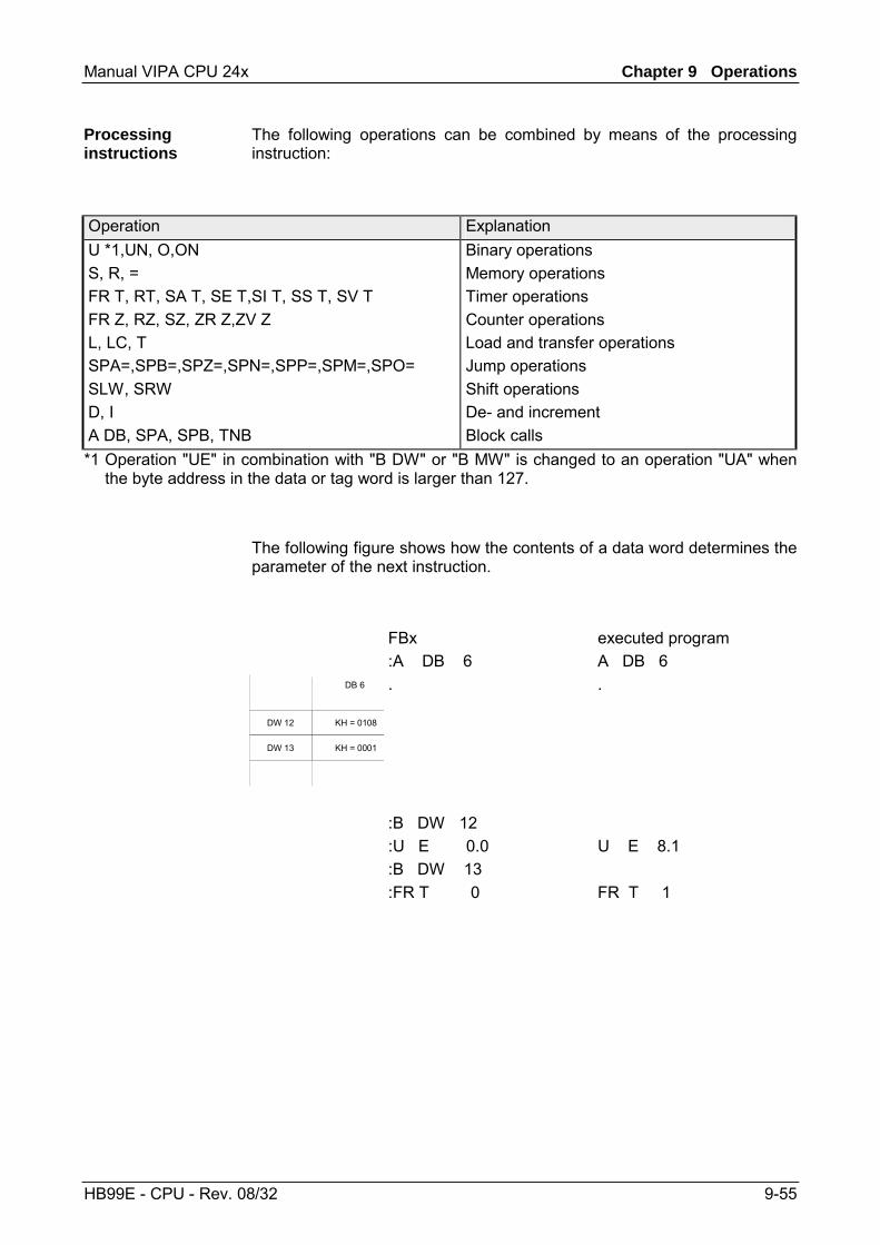
Manual VIPA CPU 24x Chapter 9 Operations
HB99E - CPU - Rev. 08/32 9-55
The following operations can be combined by means of the processing instruction:
Operation Explanation U *1,UN, O,ON S, R, = FR T, RT, SA T, SE T,SI T, SS T, SV T FR Z, RZ, SZ, ZR Z,ZV Z L, LC, T SPA=,SPB=,SPZ=,SPN=,SPP=,SPM=,SPO= SLW, SRW D, I A DB, SPA, SPB, TNB
Binary operations Memory operations Timer operations Counter operations Load and transfer operations Jump operations Shift operations De- and increment Block calls
*1 Operation "UE" in combination with "B DW" or "B MW" is changed to an operation "UA" when the byte address in the data or tag word is larger than 127.
The following figure shows how the contents of a data word determines the parameter of the next instruction.
FBx executed program :A DB 6 A DB 6
DW 12
DW 13
KH = 0108
KH = 0001
DB 6
.
.
:B DW 12 :U E 0.0 U E 8.1 :B DW 13 :FR T 0 FR T 1
Processing instructions
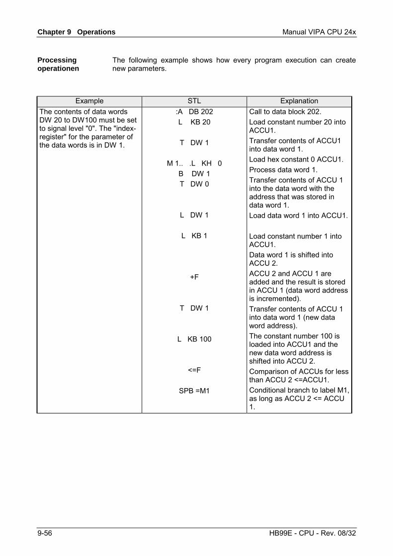
Chapter 9 Operations Manual VIPA CPU 24x
9-56 HB99E - CPU - Rev. 08/32
The following example shows how every program execution can create new parameters.
Example STL Explanation The contents of data words DW 20 to DW100 must be set to signal level "0". The "index-register" for the parameter of the data words is in DW 1.
:A DB 202 L KB 20
T DW 1
M 1.. .L KH 0
B DW 1 T DW 0
L DW 1
L KB 1
+F
T DW 1
L KB 100
<=F
SPB =M1
Call to data block 202. Load constant number 20 into ACCU1. Transfer contents of ACCU1 into data word 1. Load hex constant 0 ACCU1. Process data word 1. Transfer contents of ACCU 1 into the data word with the address that was stored in data word 1. Load data word 1 into ACCU1. Load constant number 1 into ACCU1. Data word 1 is shifted into ACCU 2. ACCU 2 and ACCU 1 are added and the result is stored in ACCU 1 (data word address is incremented). Transfer contents of ACCU 1 into data word 1 (new data word address). The constant number 100 is loaded into ACCU1 and the new data word address is shifted into ACCU 2. Comparison of ACCUs for less than ACCU 2 <=ACCU1. Conditional branch to label M1, as long as ACCU 2 <= ACCU 1.
Processing operationen
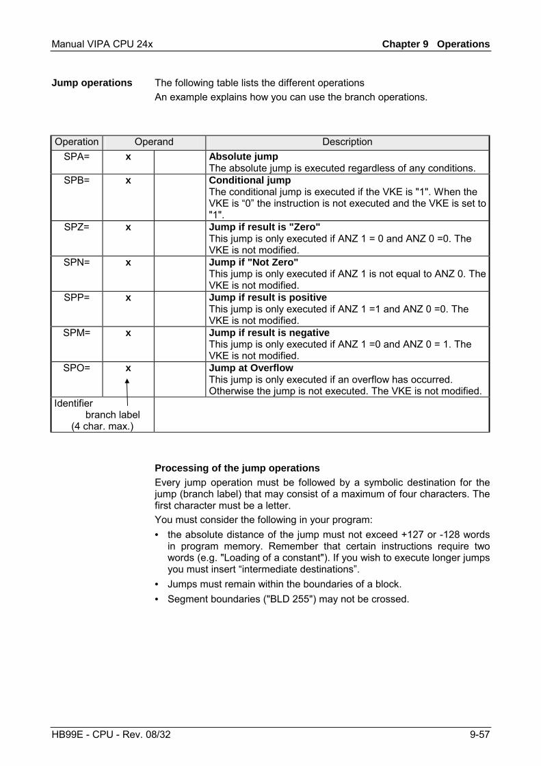
Manual VIPA CPU 24x Chapter 9 Operations
HB99E - CPU - Rev. 08/32 9-57
The following table lists the different operations An example explains how you can use the branch operations.
Operation Operand Description SPA= x Absolute jump
The absolute jump is executed regardless of any conditions. SPB= x Conditional jump
The conditional jump is executed if the VKE is "1". When the VKE is “0” the instruction is not executed and the VKE is set to "1".
SPZ= x Jump if result is "Zero" This jump is only executed if ANZ 1 = 0 and ANZ 0 =0. The VKE is not modified.
SPN= x Jump if "Not Zero" This jump is only executed if ANZ 1 is not equal to ANZ 0. The VKE is not modified.
SPP= x Jump if result is positive This jump is only executed if ANZ 1 =1 and ANZ 0 =0. The VKE is not modified.
SPM= x Jump if result is negative This jump is only executed if ANZ 1 =0 and ANZ 0 = 1. The VKE is not modified.
SPO= x Jump at Overflow This jump is only executed if an overflow has occurred. Otherwise the jump is not executed. The VKE is not modified.
Identifier branch label (4 char. max.)
Processing of the jump operations Every jump operation must be followed by a symbolic destination for the jump (branch label) that may consist of a maximum of four characters. The first character must be a letter. You must consider the following in your program: • the absolute distance of the jump must not exceed +127 or -128 words
in program memory. Remember that certain instructions require two words (e.g. "Loading of a constant"). If you wish to execute longer jumps you must insert “intermediate destinations”.
• Jumps must remain within the boundaries of a block. • Segment boundaries ("BLD 255") may not be crossed.
Jump operations
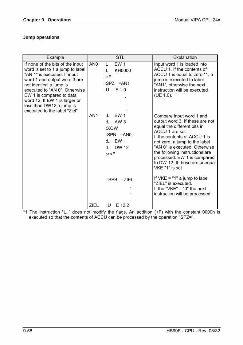
Chapter 9 Operations Manual VIPA CPU 24x
9-58 HB99E - CPU - Rev. 08/32
Example STL Explanation
If none of the bits of the input word is set to 1 a jump to label "AN 1" is executed. If input word 1 and output word 3 are not identical a jump is executed to "AN 0". Otherwise EW 1 is compared to data word 12. If EW 1 is larger or less than DW12 a jump is executed to the label "Ziel".
AN0 :L EW 1 :L KH0000 :+F :SPZ =AN1 :U E 1.0 . . . AN1 :L EW 1 :L AW 3 :XOW :SPN =AN0 :L EW 1 :L DW 12 :><F :SPB =ZIEL . . . ZIEL :U E 12.2
Input word 1 is loaded into ACCU 1. If the contents of ACCU 1 is equal to zero *1, a jump is executed to label "AN1", otherwise the next instruction will be executed (UE 1.0). Compare input word 1 and output word 3. If these are not equal the different bits in ACCU 1 are set. If the contents of ACCU 1 is not zero, a jump to the label "AN 0" is executed. Otherwise the following instructions are processed. EW 1 is compared to DW 12. If these are unequal VKE "1" is set If VKE = "1" a jump to label "ZIEL" is executed. If the "VKE" = "0" the next instruction will be processed.
*1 The instruction "L.." does not modify the flags. An addition (+F) with the constant 0000h is executed so that the contents of ACCU can be processed by the operation "SPZ=".
Jump operations
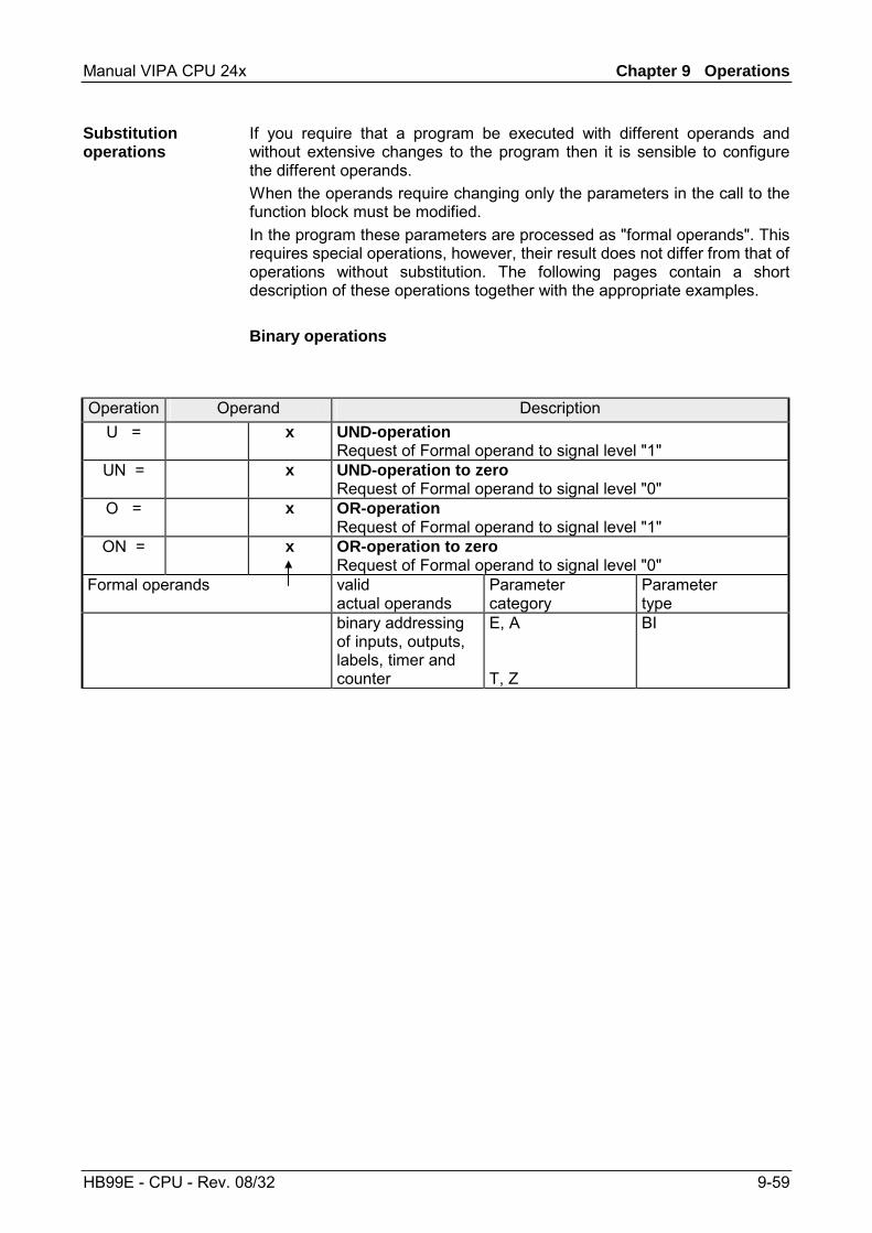
Manual VIPA CPU 24x Chapter 9 Operations
HB99E - CPU - Rev. 08/32 9-59
If you require that a program be executed with different operands and without extensive changes to the program then it is sensible to configure the different operands. When the operands require changing only the parameters in the call to the function block must be modified. In the program these parameters are processed as "formal operands". This requires special operations, however, their result does not differ from that of operations without substitution. The following pages contain a short description of these operations together with the appropriate examples. Binary operations
Operation Operand Description U = x UND-operation
Request of Formal operand to signal level "1" UN = x UND-operation to zero
Request of Formal operand to signal level "0" O = x OR-operation
Request of Formal operand to signal level "1" ON = x OR-operation to zero
Request of Formal operand to signal level "0" Formal operands
valid actual operands
Parameter category
Parameter type
binary addressing of inputs, outputs, labels, timer and counter
E, A T, Z
BI
Substitution operations
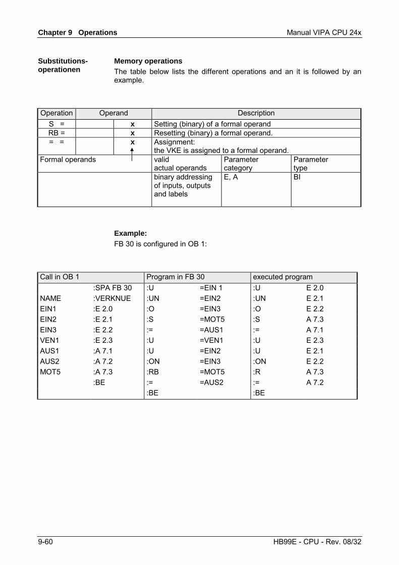
Chapter 9 Operations Manual VIPA CPU 24x
9-60 HB99E - CPU - Rev. 08/32
Memory operations The table below lists the different operations and an it is followed by an example.
Operation Operand Description S = x Setting (binary) of a formal operand RB = x Resetting (binary) a formal operand. = = x Assignment:
the VKE is assigned to a formal operand. Formal operands
valid actual operands
Parameter category
Parameter type
binary addressing of inputs, outputs and labels
E, A
BI
Example: FB 30 is configured in OB 1:
Call in OB 1 Program in FB 30 executed program :SPA FB 30 :U =EIN 1 :U E 2.0 NAME :VERKNUE :UN =EIN2 :UN E 2.1 EIN1 :E 2.0 :O =EIN3 :O E 2.2 EIN2 :E 2.1 :S =MOT5 :S A 7.3 EIN3 :E 2.2 := =AUS1 := A 7.1 VEN1 :E 2.3 :U =VEN1 :U E 2.3 AUS1 :A 7.1 :U =EIN2 :U E 2.1 AUS2 :A 7.2 :ON =EIN3 :ON E 2.2 MOT5 :A 7.3 :RB =MOT5 :R A 7.3 :BE := =AUS2 := A 7.2 :BE :BE
Substitutions-operationen

Manual VIPA CPU 24x Chapter 9 Operations
HB99E - CPU - Rev. 08/32 9-61
Load and transfer operations The following table lists the different operations and explained by an example.
Operation Operand Description L = x Load a formal operand LC = x Load coded a formal operand LW = x Load the bit pattern of a formal operand T = x Transfer into a formal operand
Formal operands
valid actual operands
Parameter category
Parameter type
for L =
byte- and word addressed inputs, outputs and labels *1 Timers and counters
E,A T,Z
BY,W
for LC =
Timers and counters
T,Z
for LW =
Bit patterns D
KF, KH, KM, KY, KC, KT, KZ
for T =
byte- and word addressed inputs, outputs and labels *1
E,A
BY,W
*1 Data word: DW, DR, DL
Substitution operations
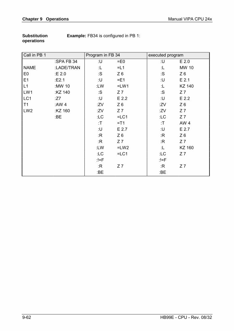
Chapter 9 Operations Manual VIPA CPU 24x
9-62 HB99E - CPU - Rev. 08/32
Example: FB34 is configured in PB 1:
Call in PB 1 Program in FB 34 executed program :SPA FB 34 :U =E0 :U E 2.0 NAME :LADE/TRAN :L =L1 :L MW 10 E0 :E 2.0 :S Z 6 :S Z 6 E1 :E2.1 :U =E1 :U E 2.1 L1 :MW 10 :LW =LW1 :L KZ 140 LW1 :KZ 140 :S Z 7 :S Z 7 LC1 :Z7 :U E 2.2 :U E 2.2 T1 :AW 4 :ZV Z 6 :ZV Z 6 LW2 :KZ 160 :ZV Z 7 :ZV Z 7 :BE :LC =LC1 :LC Z 7 :T =T1 :T AW 4 :U E 2.7 :U E 2.7 :R Z 6 :R Z 6 :R Z 7 :R Z 7 :LW =LW2 :L KZ 160 :LC =LC1 :LC Z 7 :!=F :!=F :R Z 7 :R Z 7 :BE :BE
Substitution operations
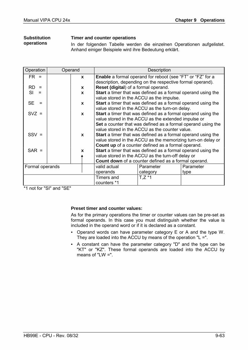
Manual VIPA CPU 24x Chapter 9 Operations
HB99E - CPU - Rev. 08/32 9-63
Timer and counter operations In der folgenden Tabelle werden die einzelnen Operationen aufgelistet. Anhand einiger Beispiele wird ihre Bedeutung erklärt.
Operation Operand Description FR = x Enable a formal operand for reboot (see “FT” or “FZ” for a
description, depending on the respective formal operand). RD = x Reset (digital) of a formal operand. SI = x Start a timer that was defined as a formal operand using the
value stored in the ACCU as the impulse. SE = x Start a timer that was defined as a formal operand using the
value stored in the ACCU as the turn-on delay. SVZ = x Start a timer that was defined as a formal operand using the
value stored in the ACCU as the extended impulse or Set a counter that was defined as a formal operand using the value stored in the ACCU as the counter value.
SSV = x Start a timer that was defined as a formal operand using the value stored in the ACCU as the memorizing turn-on delay or Count up of a counter defined as a formal operand.
SAR = x Start a timer that was defined as a formal operand using the value stored in the ACCU as the turn-off delay or Count down of a counter defined as a formal operand.
Formal operands
valid actual operands
Parameter category
Parameter type
Timers and counters *1
T,Z *1
*1 not for "SI" and "SE"
Preset timer and counter values: As for the primary operations the timer or counter values can be pre-set as formal operands. In this case you must distinguish whether the value is included in the operand word or if it is declared as a constant. • Operand words can have parameter category E or A and the type W.
They are loaded into the ACCU by means of the operation "L =". • A constant can have the parameter category "D" and the type can be
"KT" or "KZ". These formal operands are loaded into the ACCU by means of "LW =".
Substitution operations
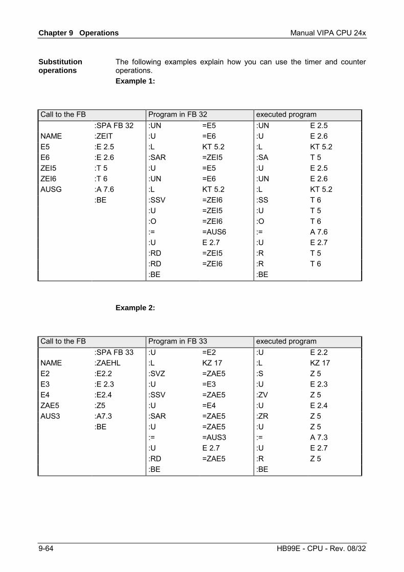
Chapter 9 Operations Manual VIPA CPU 24x
9-64 HB99E - CPU - Rev. 08/32
The following examples explain how you can use the timer and counter operations. Example 1:
Call to the FB Program in FB 32 executed program :SPA FB 32 :UN =E5 :UN E 2.5 NAME :ZEIT :U =E6 :U E 2.6 E5 :E 2.5 :L KT 5.2 :L KT 5.2 E6 :E 2.6 :SAR =ZEI5 :SA T 5 ZEI5 :T 5 :U =E5 :U E 2.5 ZEI6 :T 6 :UN =E6 :UN E 2.6 AUSG :A 7.6 :L KT 5.2 :L KT 5.2 :BE :SSV =ZEI6 :SS T 6 :U =ZEI5 :U T 5 :O =ZEI6 :O T 6 := =AUS6 := A 7.6 :U E 2.7 :U E 2.7 :RD =ZEI5 :R T 5 :RD =ZEI6 :R T 6 :BE :BE
Example 2:
Call to the FB Program in FB 33 executed program :SPA FB 33 :U =E2 :U E 2.2 NAME :ZAEHL :L KZ 17 :L KZ 17 E2 :E2.2 :SVZ =ZAE5 :S Z 5 E3 :E 2.3 :U =E3 :U E 2.3 E4 :E2.4 :SSV =ZAE5 :ZV Z 5 ZAE5 :Z5 :U =E4 :U E 2.4 AUS3 :A7.3 :SAR =ZAE5 :ZR Z 5 :BE :U =ZAE5 :U Z 5 := =AUS3 := A 7.3 :U E 2.7 :U E 2.7 :RD =ZAE5 :R Z 5 :BE :BE
Substitution operations

Manual VIPA CPU 24x Chapter 9 Operations
HB99E - CPU - Rev. 08/32 9-65
Processing operation This operation is explained by the table an example:
Operation Operand Description B = x Processing of as formal operand
The substituted blocks are called regardless of the conditions (absolute).
Formal operands
valid actual operands
Parameter category
Parameter type
DB, PB, SB, FB *1 B *1 As actual operands the function blocks may not contain block parameters.
Example:
Call to the FB Program in FB 35 executed program :SPA FB 35 :B =D5 :A DB 5 NAME :BEARB. :L =DW2 :L DW 2 D5 :DB 5 :B =D6 :A DB 6 DW2 :DW 2 :T =DW1 :T DW1 D6 :DB6 :T =A4 :T AW 4 DW1 :DW1 :B =MOT5 :SPA FB 36 A4 :AW 4 :BE :BE MOT5 :FB36 :BE
Substitution operations
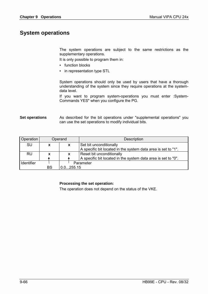
Chapter 9 Operations Manual VIPA CPU 24x
9-66 HB99E - CPU - Rev. 08/32
System operations
The system operations are subject to the same restrictions as the supplementary operations. It is only possible to program them in: • function blocks • in representation type STL System operations should only be used by users that have a thorough understanding of the system since they require operations at the system-data level. If you want to program system-operations you must enter :System-Commands YES" when you configure the PG.
As described for the bit operations under "supplemental operations" you can use the set operations to modify individual bits.
Operation Operand Description SU x x Set bit unconditionally
A specific bit located in the system data area is set to "1". RU x x Reset bit unconditionally
A specific bit located in the system data area is set to "0". Identifier BS
Parameter 0.0...255.15
Processing the set operation: The operation does not depend on the status of the VKE.
Set operations
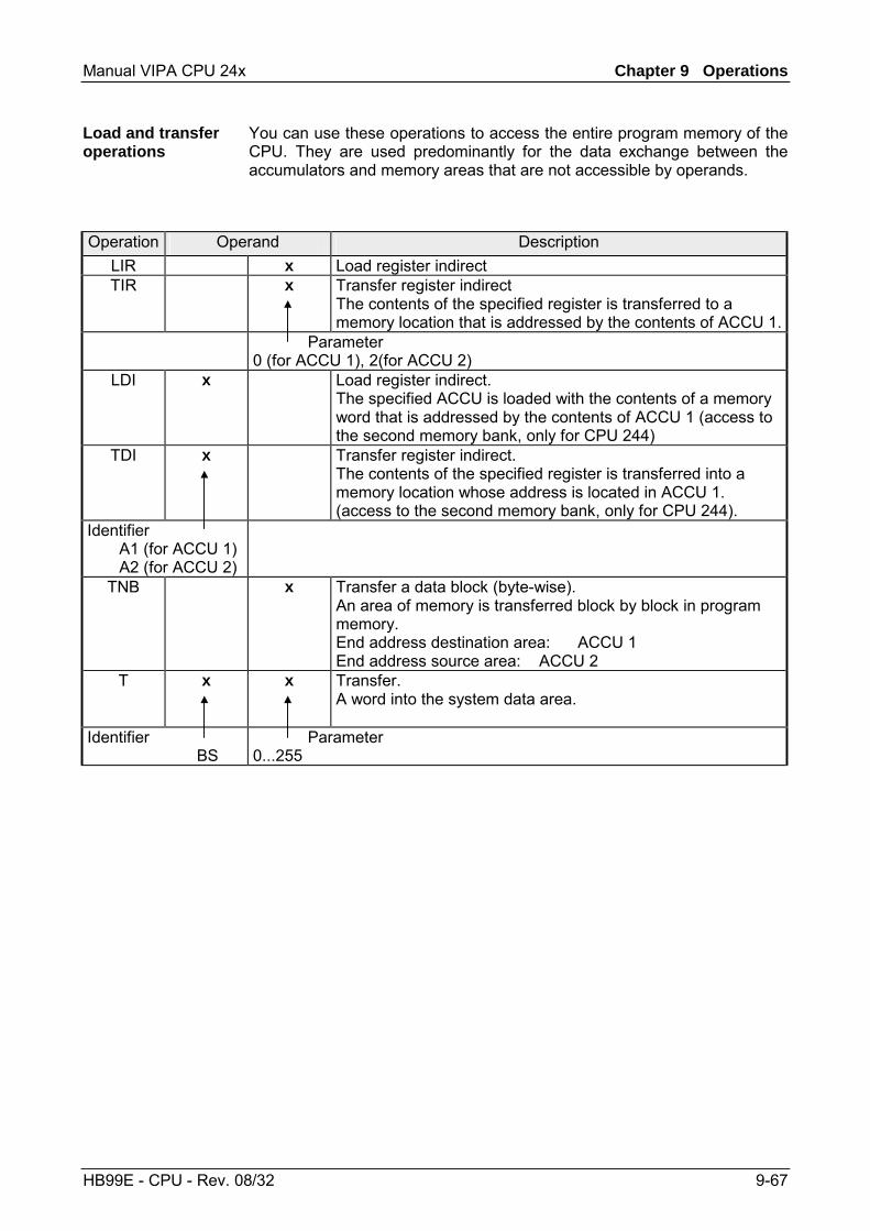
Manual VIPA CPU 24x Chapter 9 Operations
HB99E - CPU - Rev. 08/32 9-67
You can use these operations to access the entire program memory of the CPU. They are used predominantly for the data exchange between the accumulators and memory areas that are not accessible by operands.
Operation Operand Description LIR x Load register indirect TIR x Transfer register indirect
The contents of the specified register is transferred to a memory location that is addressed by the contents of ACCU 1.
Parameter 0 (for ACCU 1), 2(for ACCU 2)
LDI x Load register indirect. The specified ACCU is loaded with the contents of a memory word that is addressed by the contents of ACCU 1 (access to the second memory bank, only for CPU 244)
TDI x Transfer register indirect. The contents of the specified register is transferred into a memory location whose address is located in ACCU 1. (access to the second memory bank, only for CPU 244).
Identifier A1 (for ACCU 1) A2 (for ACCU 2)
TNB x Transfer a data block (byte-wise). An area of memory is transferred block by block in program memory. End address destination area: ACCU 1 End address source area: ACCU 2
T x x Transfer. A word into the system data area.
Identifier BS
Parameter 0...255
Load and transfer operations
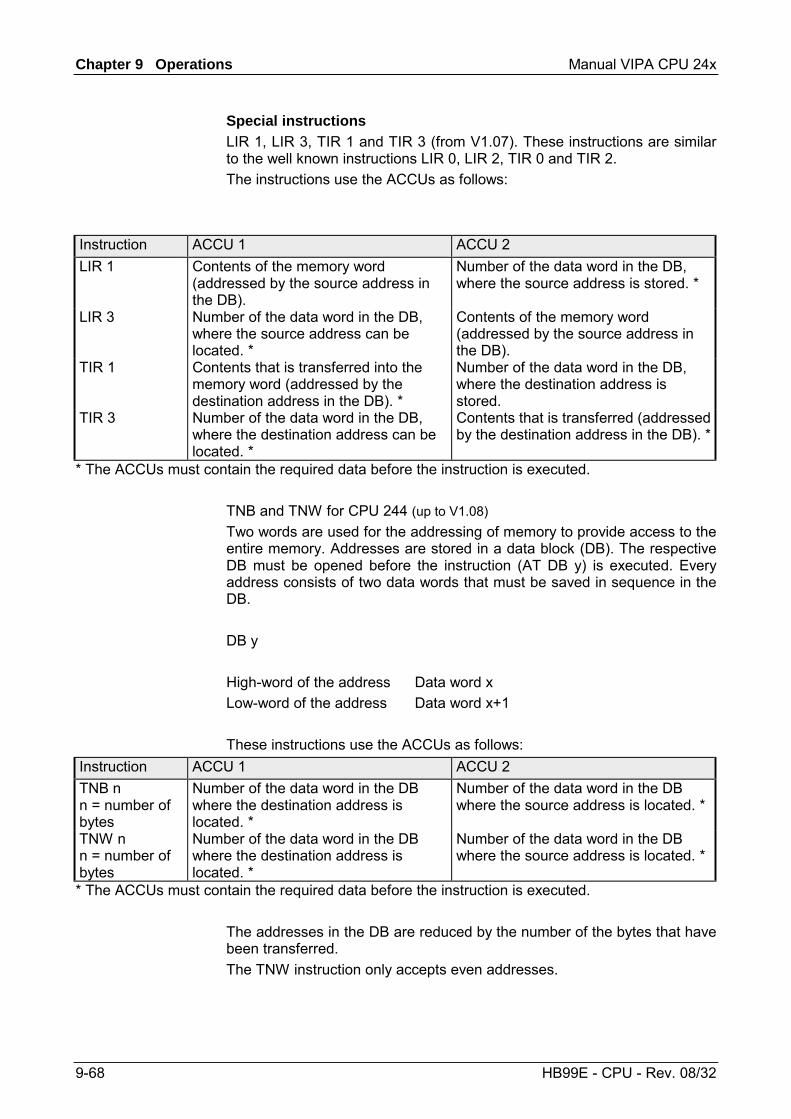
Chapter 9 Operations Manual VIPA CPU 24x
9-68 HB99E - CPU - Rev. 08/32
Special instructions LIR 1, LIR 3, TIR 1 and TIR 3 (from V1.07). These instructions are similar to the well known instructions LIR 0, LIR 2, TIR 0 and TIR 2. The instructions use the ACCUs as follows:
Instruction ACCU 1 ACCU 2 LIR 1 Contents of the memory word
(addressed by the source address in the DB).
Number of the data word in the DB, where the source address is stored. *
LIR 3 Number of the data word in the DB, where the source address can be located. *
Contents of the memory word (addressed by the source address in the DB).
TIR 1 Contents that is transferred into the memory word (addressed by the destination address in the DB). *
Number of the data word in the DB, where the destination address is stored.
TIR 3 Number of the data word in the DB, where the destination address can be located. *
Contents that is transferred (addressed by the destination address in the DB). *
* The ACCUs must contain the required data before the instruction is executed. TNB and TNW for CPU 244 (up to V1.08) Two words are used for the addressing of memory to provide access to the entire memory. Addresses are stored in a data block (DB). The respective DB must be opened before the instruction (AT DB y) is executed. Every address consists of two data words that must be saved in sequence in the DB. DB y High-word of the address Data word x Low-word of the address Data word x+1 These instructions use the ACCUs as follows:
Instruction ACCU 1 ACCU 2 TNB n n = number of bytes
Number of the data word in the DB where the destination address is located. *
Number of the data word in the DB where the source address is located. *
TNW n n = number of bytes
Number of the data word in the DB where the destination address is located. *
Number of the data word in the DB where the source address is located. *
* The ACCUs must contain the required data before the instruction is executed. The addresses in the DB are reduced by the number of the bytes that have been transferred. The TNW instruction only accepts even addresses.
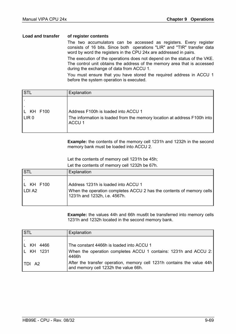
Manual VIPA CPU 24x Chapter 9 Operations
HB99E - CPU - Rev. 08/32 9-69
of register contents The two accumulators can be accessed as registers. Every register consists of 16 bits. Since both operations "LIR" and "TIR" transfer data word by word the registers in the CPU 24x are addressed in pairs. The execution of the operations does not depend on the status of the VKE. The control unit obtains the address of the memory area that is accessed during the exchange of data from ACCU 1. You must ensure that you have stored the required address in ACCU 1 before the system operation is executed.
STL Explanation . . L KH F100 LIR 0
Address F100h is loaded into ACCU 1 The information is loaded from the memory location at address F100h into ACCU 1 Example: the contents of the memory cell 1231h and 1232h in the second memory bank must be loaded into ACCU 2. Let the contents of memory cell 1231h be 45h; Let the contents of memory cell 1232h be 67h.
STL Explanation . L KH F100 LDI A2
Address 1231h is loaded into ACCU 1 When the operation completes ACCU 2 has the contents of memory cells 1231h and 1232h, i.e. 4567h. Example: the values 44h and 66h mus6t be transferred into memory cells 1231h and 1232h located in the second memory bank.
STL Explanation . L KH 4466 L KH 1231 TDI A2
The constant 4466h is loaded into ACCU 1 When the operation completes ACCU 1 contains: 1231h and ACCU 2: 4466h After the transfer operation, memory cell 1231h contains the value 44h and memory cell 1232h the value 66h.
Load and transfer
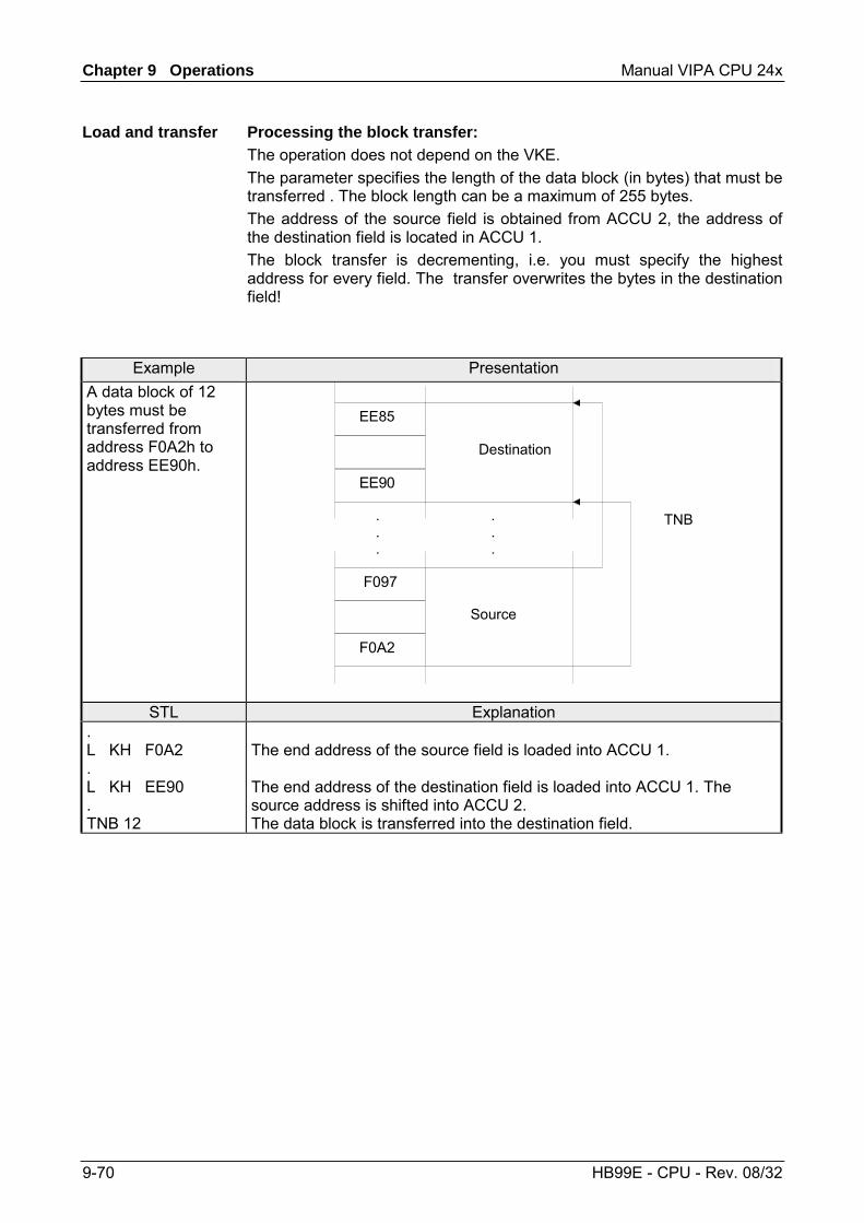
Chapter 9 Operations Manual VIPA CPU 24x
9-70 HB99E - CPU - Rev. 08/32
Processing the block transfer: The operation does not depend on the VKE. The parameter specifies the length of the data block (in bytes) that must be transferred . The block length can be a maximum of 255 bytes. The address of the source field is obtained from ACCU 2, the address of the destination field is located in ACCU 1. The block transfer is decrementing, i.e. you must specify the highest address for every field. The transfer overwrites the bytes in the destination field!
Example Presentation A data block of 12 bytes must be transferred from address F0A2h to address EE90h.
EE85
EE90
F097
F0A2
Source
Destination
.
.
.
.
.
.
TNB
STL Explanation . L KH F0A2 . L KH EE90 . TNB 12
The end address of the source field is loaded into ACCU 1. The end address of the destination field is loaded into ACCU 1. The source address is shifted into ACCU 2. The data block is transferred into the destination field.
Load and transfer

Manual VIPA CPU 24x Chapter 9 Operations
HB99E - CPU - Rev. 08/32 9-71
Transfer into the system data area Example: After every STOP®RUN change of mode the cycle time limit should be set to 100 ms. This time can be programmed as a multiple of 10 ms in system data-word 96 (not for CPU 241). The next function block can then be called, for example, from OB 21:
STL Explanation . FB 11 . L KF 10 . T BS 96 BE
Type and number of the block. Factor 10 is loaded into ACCU 1. This value is transferred into system data word 96.
Note! The operations TIR, TDI, TS BS and TNB modify the contents of memory in the user data area as well as the system data area that is not under the control of the operating system. Improper use of the operation can lead to the program changes and to CPU crashes.
Load and transfer
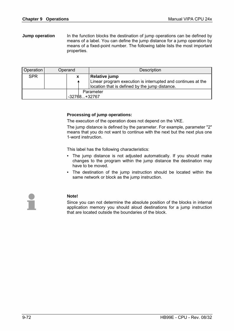
Chapter 9 Operations Manual VIPA CPU 24x
9-72 HB99E - CPU - Rev. 08/32
In the function blocks the destination of jump operations can be defined by means of a label. You can define the jump distance for a jump operation by means of a fixed-point number. The following table lists the most important properties.
Operation Operand Description SPR x Relative jump
Linear program execution is interrupted and continues at the location that is defined by the jump distance.
Parameter -32768...+32767
Processing of jump operations: The execution of the operation does not depend on the VKE. The jump distance is defined by the parameter. For example, parameter "2" means that you do not want to continue with the next but the next plus one 1-word instruction. This label has the following characteristics: • The jump distance is not adjusted automatically. If you should make
changes to the program within the jump distance the destination may have to be moved.
• The destination of the jump instruction should be located within the same network or block as the jump instruction.
Note! Since you can not determine the absolute position of the blocks in internal application memory you should aloud destinations for a jump instruction that are located outside the boundaries of the block.
Jump operation
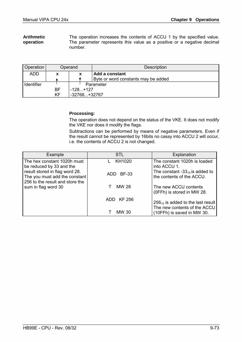
Manual VIPA CPU 24x Chapter 9 Operations
HB99E - CPU - Rev. 08/32 9-73
The operation increases the contents of ACCU 1 by the specified value. The parameter represents this value as a positive or a negative decimal number.
Operation Operand Description ADD x x Add a constant
Byte or word constants may be added Identifier BF KF
Parameter -128...+127 -32768...+32767
Processing: The operation does not depend on the status of the VKE. It does not modify the VKE nor does it modify the flags. Subtractions can be performed by means of negative parameters. Even if the result cannot be represented by 16bits no cassy into ACCU 2 will occur, i.e. the contents of ACCU 2 is not changed.
Example STL Explanation The hex constant 1020h must be reduced by 33 and the result stored in flag word 28. The you must add the constant 256 to the result and store the sum in flag word 30
L KH1020
ADD BF-33
T MW 28
ADD KF 256
T MW 30
The constant 1020h is loaded into ACCU 1. The constant -3310 is added to the contents of the ACCU. The new ACCU contents (0FFh) is stored in MW 28. 25610 is added to the last result The new contents of the ACCU (10FFh) is saved in MW 30.
Arithmetic operation
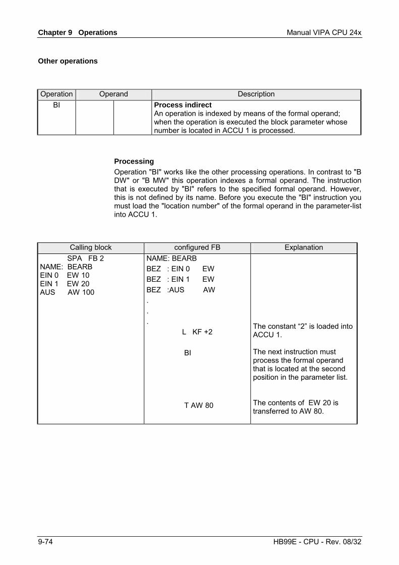
Chapter 9 Operations Manual VIPA CPU 24x
9-74 HB99E - CPU - Rev. 08/32
Operation Operand Description
BI Process indirect An operation is indexed by means of the formal operand; when the operation is executed the block parameter whose number is located in ACCU 1 is processed.
Processing Operation "BI" works like the other processing operations. In contrast to "B DW" or "B MW" this operation indexes a formal operand. The instruction that is executed by "BI" refers to the specified formal operand. However, this is not defined by its name. Before you execute the "BI" instruction you must load the "location number" of the formal operand in the parameter-list into ACCU 1.
Calling block configured FB Explanation SPA FB 2 NAME: BEARB EIN 0 EW 10 EIN 1 EW 20 AUS AW 100
NAME: BEARB BEZ : EIN 0 EW BEZ : EIN 1 EW BEZ :AUS AW . . . L KF +2 BI T AW 80
The constant “2” is loaded into ACCU 1. The next instruction must process the formal operand that is located at the second position in the parameter list. The contents of EW 20 is transferred to AW 80.
Other operations
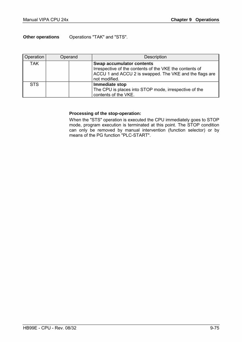
Manual VIPA CPU 24x Chapter 9 Operations
HB99E - CPU - Rev. 08/32 9-75
Operations "TAK" and "STS".
Operation Operand Description TAK Swap accumulator contents
Irrespective of the contents of the VKE the contents of ACCU 1 and ACCU 2 is swapped. The VKE and the flags are not modified.
STS Immediate stop The CPU is places into STOP mode, irrespective of the contents of the VKE.
Processing of the stop-operation: When the "STS" operation is executed the CPU immediately goes to STOP mode, program execution is terminated at this point. The STOP condition can only be removed by manual intervention (function selector) or by means of the PG function "PLC-START".
Other operations

Chapter 9 Operations Manual VIPA CPU 24x
9-76 HB99E - CPU - Rev. 08/32
Setting of flags
The control unit has three flags: • ANZ 0, • ANZ 1, • OV overflow. These flags are modified by different operations: • comparison operations, • arithmetic operations, • shift operations, • and certain conversion operations. The status of the flags represent a condition for the different jump operations. Flags set by the different comparison operations: When comparison operations are executed flags ANZ 0 and ANZ 1 are modified. The overflow flag does not change. However, comparison operations modify the result of logical operations. When the result is true the VKE is = 1. For this reason the conditional jump "SPB" can be used after a comparison operation.
Contents of ACCU 2 with respect to
ACCU 1
Flags Possible jump operations
ANZ 1 ANZ 0 O V equal 0 0 SPZ
less than 0 1 SPN, SPM larger than 1 0 SPN, SPP
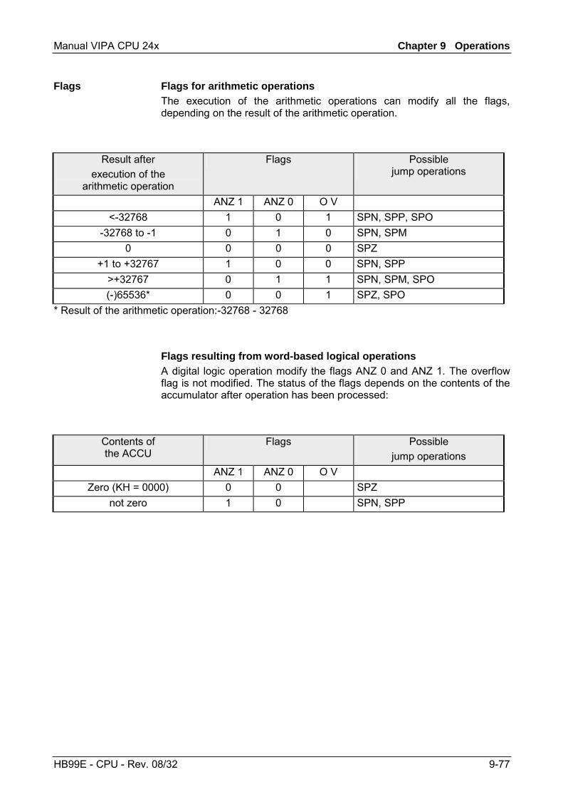
Manual VIPA CPU 24x Chapter 9 Operations
HB99E - CPU - Rev. 08/32 9-77
Flags for arithmetic operations The execution of the arithmetic operations can modify all the flags, depending on the result of the arithmetic operation.
Result after execution of the
arithmetic operation
Flags Possible jump operations
ANZ 1 ANZ 0 O V <-32768 1 0 1 SPN, SPP, SPO
-32768 to -1 0 1 0 SPN, SPM 0 0 0 0 SPZ
+1 to +32767 1 0 0 SPN, SPP >+32767 0 1 1 SPN, SPM, SPO (-)65536* 0 0 1 SPZ, SPO
* Result of the arithmetic operation:-32768 - 32768
Flags resulting from word-based logical operations A digital logic operation modify the flags ANZ 0 and ANZ 1. The overflow flag is not modified. The status of the flags depends on the contents of the accumulator after operation has been processed:
Contents of the ACCU
Flags Possible jump operations
ANZ 1 ANZ 0 O V Zero (KH = 0000) 0 0 SPZ
not zero 1 0 SPN, SPP
Flags
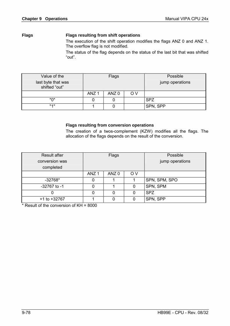
Chapter 9 Operations Manual VIPA CPU 24x
9-78 HB99E - CPU - Rev. 08/32
Flags resulting from shift operations The execution of the shift operation modifies the flags ANZ 0 and ANZ 1. The overflow flag is not modified. The status of the flag depends on the status of the last bit that was shifted “out”.
Value of the last byte that was
shifted “out”
Flags Possible jump operations
ANZ 1 ANZ 0 O V "0" 0 0 SPZ "1" 1 0 SPN, SPP
Flags resulting from conversion operations The creation of a twos-complement (KZW) modifies all the flags. The allocation of the flags depends on the result of the conversion.
Result after conversion was
completed
Flags Possible jump operations
ANZ 1 ANZ 0 O V -32768* 0 1 1 SPN, SPM, SPO
-32767 to -1 0 1 0 SPN, SPM 0 0 0 0 SPZ
+1 to +32767 1 0 0 SPN, SPP * Result of the conversion of KH = 8000
Flags
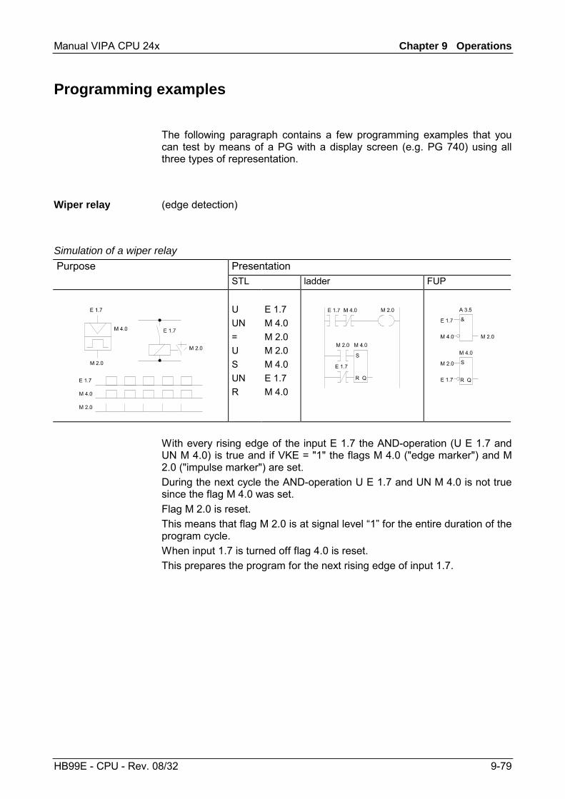
Manual VIPA CPU 24x Chapter 9 Operations
HB99E - CPU - Rev. 08/32 9-79
Programming examples
The following paragraph contains a few programming examples that you can test by means of a PG with a display screen (e.g. PG 740) using all three types of representation.
(edge detection)
Simulation of a wiper relay Purpose Presentation STL ladder FUP
U UN = U S UN R
E 1.7 M 4.0 M 2.0 M 2.0 M 4.0 E 1.7 M 4.0
With every rising edge of the input E 1.7 the AND-operation (U E 1.7 and UN M 4.0) is true and if VKE = "1" the flags M 4.0 ("edge marker") and M 2.0 ("impulse marker") are set. During the next cycle the AND-operation U E 1.7 and UN M 4.0 is not true since the flag M 4.0 was set. Flag M 2.0 is reset. This means that flag M 2.0 is at signal level “1” for the entire duration of the program cycle. When input 1.7 is turned off flag 4.0 is reset. This prepares the program for the next rising edge of input 1.7.
Wiper relay
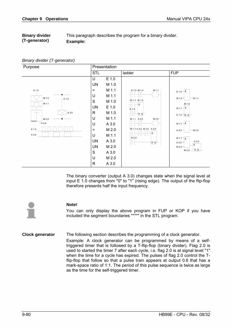
Chapter 9 Operations Manual VIPA CPU 24x
9-80 HB99E - CPU - Rev. 08/32
This paragraph describes the program for a binary divider. Example:
Binary divider (T-generator) Purpose Presentation STL ladder FUP
U UN = U S UN R U U = U UN UN S U R
E 1.0 M 1.0 M 1.1 M 1.1 M 1.0 E 1.0 M 1.0 M 1.1 A 3.0 M 2.0 M 1.1 A 3.0 M 2.0 A 3.0 M 2.0 A 3.0
The binary converter (output A 3.0) changes state when the signal level at input E 1.0 changes from "0" to "1" (rising edge). The output of the flip-flop therefore presents half the input frequency.
Note! You can only display the above program in FUP or KOP if you have included the segment boundaries "***" in the STL program.
The following section describes the programming of a clock generator. Example: A clock generator can be programmed by means of a self-triggered timer that is followed by a T-flip-flop (binary divider). Flag 2.0 is used to started the timer 7 after each cycle, i.e. flag 2.0 is at signal level "1" when the time for a cycle has expired. The pulses of flag 2.0 control the T-flip-flop that follow so that a pulse train appears at output 0.6 that has a mark-space ratio of 1:1. The period of this pulse sequence is twice as large as the time for the self-triggered timer.
Binary divider (T-generator)
Clock generator
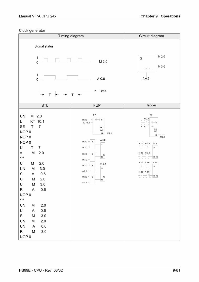
Manual VIPA CPU 24x Chapter 9 Operations
HB99E - CPU - Rev. 08/32 9-81
Clock generator Timing diagram Circuit diagram
Signal status
Time
M 2.0
A 0.6
T T
01
01
A 0.6
M 2.0
M 3.0
G
STL FUP ladder UN M 2.0 L KT 10.1 SE T 7 NOP 0 NOP 0 NOP 0 U T 7 = M 2.0 *** U M 2.0 UN M 3.0 S A 0.6 U M 2.0 U M 3.0 R A 0.6 NOP 0 *** UN M 2.0 U A 0.6 S M 3.0 UN M 2.0 UN A 0.6 R M 3.0 NOP 0
M 2.0
M 3.0
&
M 2.0
M 3.0
&
M 2.0
A 0.6
&
M 2.0
A 0.6
&
S
S
R
R
Q
Q
A 0.6
M 3.0
M 2.0KT 10.1
T 7
T 0
DUDEQ M 2.0
M 2.0 M 3.0
M 2.0 M 3.0
M 2.0 A 0.6
M 2.0 A 0.6
S
S
R
R
Q
Q
A 0.6
M 3.0
M 2.0
KT 10.1 TW
T 0
T 7
D UDE
QM 2.0
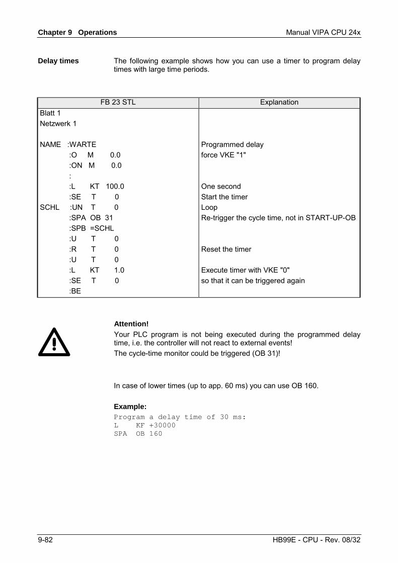
Chapter 9 Operations Manual VIPA CPU 24x
9-82 HB99E - CPU - Rev. 08/32
The following example shows how you can use a timer to program delay times with large time periods.
FB 23 STL Explanation Blatt 1 Netzwerk 1 NAME :WARTE :O M 0.0 :ON M 0.0 : :L KT 100.0 :SE T 0 SCHL :UN T 0 :SPA OB 31 :SPB =SCHL :U T 0 :R T 0 :U T 0 :L KT 1.0 :SE T 0 :BE
Programmed delay force VKE "1" One second Start the timer Loop Re-trigger the cycle time, not in START-UP-OB Reset the timer Execute timer with VKE "0" so that it can be triggered again
Attention! Your PLC program is not being executed during the programmed delay time, i.e. the controller will not react to external events! The cycle-time monitor could be triggered (OB 31)!
In case of lower times (up to app. 60 ms) you can use OB 160. Example: Program a delay time of 30 ms: L KF +30000 SPA OB 160
Delay times

Manual VIPA CPU 24x Chapter 10 Integrated Blocks
HB99E - CPU - Rev. 08/32 10-1
Chapter 10 Integrated Blocks
The chapter begins with a summary of all the integrated blocks. This is followed by a description of the blocks. This section also contains the description of the (standard) handler blocks that are provided for use in with communication tasks. The chapter then continues with the integrated OBs. A description of the integrated DB 1 and the related programming environment concludes the chapter. Topic Page Chapter 10 Integrated Blocks.......................................................... 10-1
Integrated functions ......................................................................................... 10-2 FB 238 - COMPR (compress).......................................................................... 10-3 FB 239 - DELETE ............................................................................................ 10-4 FB 240 - COD:B4 (code conversion BCD/DUAL)............................................ 10-5 FB 241 - COD:16 (code conversion DUAL/BCD) ............................................ 10-6 FB 242 - MUL:16 (Multiplier)............................................................................ 10-7 FB 243 - DIV:16 (Divider)................................................................................. 10-8 FB 250 - RLG:AE (Read an normalize an analog value)................................. 10-9 FB 251 - RLG:AA (Analog value output)........................................................ 10-12 Example of analog data processing............................................................... 10-14 Integrated handler blocks............................................................................... 10-17 The handler block parameters ....................................................................... 10-18 Parameter description of the handler blocks ................................................. 10-19 Configuration of SSNR, A-NR, ANZW and BLGR ......................................... 10-21 Indirect configuration of source- and destination identifiers .......................... 10-24 Table of the possible QTYP/ZTYP parameters ............................................. 10-25 Indicator word structure ................................................................................. 10-27 Status and error indicator in the indicator word ............................................. 10-28 Indicator word................................................................................................. 10-29 Length - Word ................................................................................................ 10-35 Structure of the configuration error indicator byte.......................................... 10-36 Adjustable block size ..................................................................................... 10-37 FB 244 - SEND .............................................................................................. 10-38 FB 245 - RECEIVE ........................................................................................ 10-41 FB 246 - FETCH ............................................................................................ 10-44 FB 247 - CONTROL....................................................................................... 10-45 FB 248 - RESET ............................................................................................ 10-46 FB 249 - SYCHRON ...................................................................................... 10-47 Integrated special organization blocks........................................................... 10-48 OB 31 - Cycle time triggering......................................................................... 10-49 OB 160 - Variable timing loop........................................................................ 10-50 OB 251 - PID control algorithm...................................................................... 10-51 Integrated block DB 1 .................................................................................... 10-61
Outline
Contents
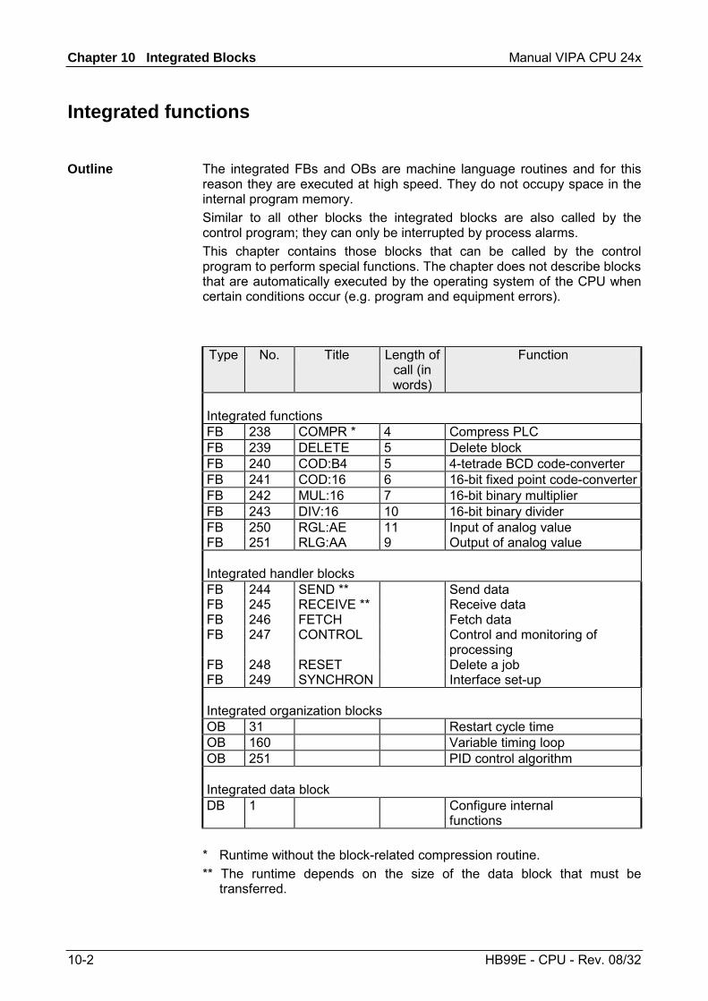
Chapter 10 Integrated Blocks Manual VIPA CPU 24x
10-2 HB99E - CPU - Rev. 08/32
Integrated functions
The integrated FBs and OBs are machine language routines and for this reason they are executed at high speed. They do not occupy space in the internal program memory. Similar to all other blocks the integrated blocks are also called by the control program; they can only be interrupted by process alarms. This chapter contains those blocks that can be called by the control program to perform special functions. The chapter does not describe blocks that are automatically executed by the operating system of the CPU when certain conditions occur (e.g. program and equipment errors).
Type No. Title Length of call (in words)
Function
Integrated functions FB 238 COMPR * 4 Compress PLC FB 239 DELETE 5 Delete block FB 240 COD:B4 5 4-tetrade BCD code-converter FB 241 COD:16 6 16-bit fixed point code-converterFB 242 MUL:16 7 16-bit binary multiplier FB 243 DIV:16 10 16-bit binary divider FB 250 RGL:AE 11 Input of analog value FB 251 RLG:AA 9 Output of analog value Integrated handler blocks FB 244 SEND ** Send data FB 245 RECEIVE ** Receive data FB 246 FETCH Fetch data FB 247 CONTROL Control and monitoring of
processing FB 248 RESET Delete a job FB 249 SYNCHRON Interface set-up Integrated organization blocks OB 31 Restart cycle time OB 160 Variable timing loop OB 251 PID control algorithm Integrated data block DB 1 Configure internal
functions * Runtime without the block-related compression routine. ** The runtime depends on the size of the data block that must be
transferred.
Outline
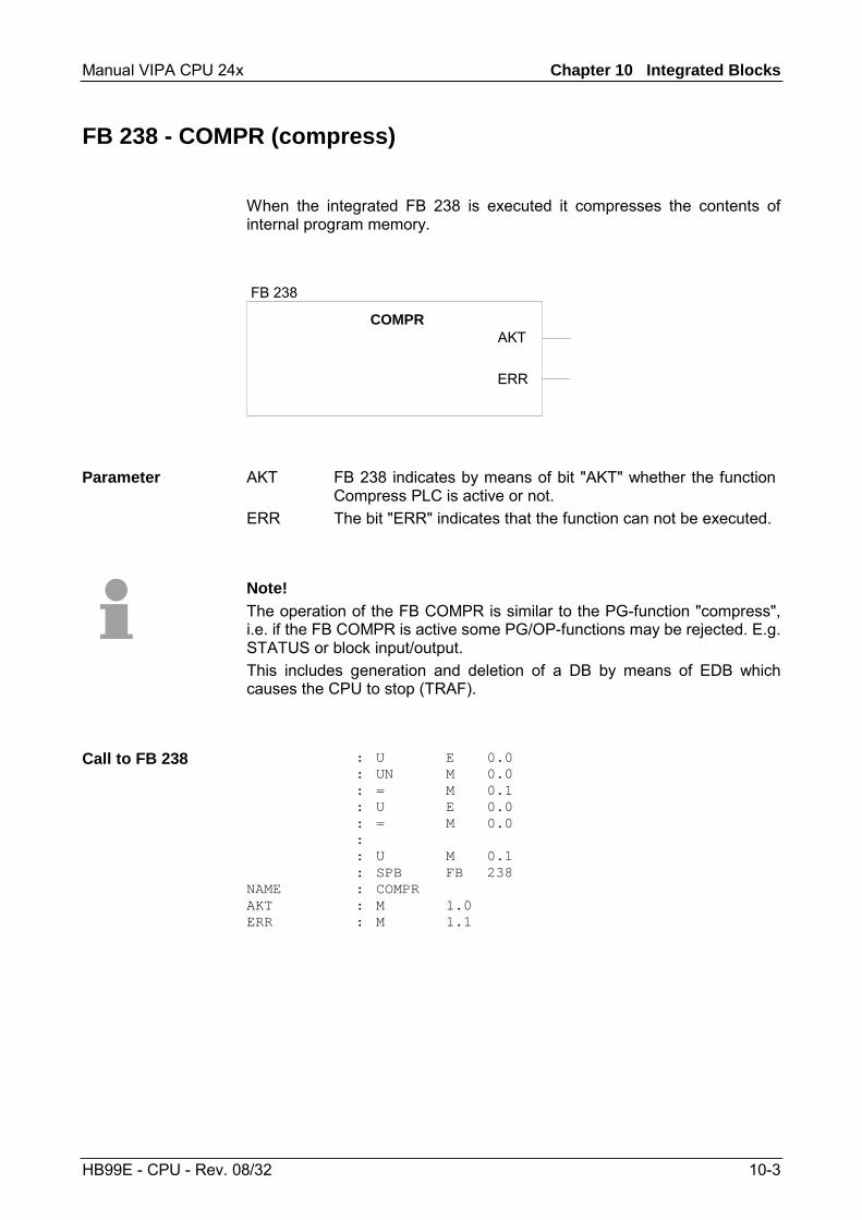
Manual VIPA CPU 24x Chapter 10 Integrated Blocks
HB99E - CPU - Rev. 08/32 10-3
FB 238 - COMPR (compress)
When the integrated FB 238 is executed it compresses the contents of internal program memory.
ERR
FB 238
COMPRAKT
AKT FB 238 indicates by means of bit "AKT" whether the function Compress PLC is active or not.
ERR The bit "ERR" indicates that the function can not be executed.
Note! The operation of the FB COMPR is similar to the PG-function "compress", i.e. if the FB COMPR is active some PG/OP-functions may be rejected. E.g. STATUS or block input/output. This includes generation and deletion of a DB by means of EDB which causes the CPU to stop (TRAF).
: U E 0.0 : UN M 0.0 : = M 0.1 : U E 0.0 : = M 0.0 : : U M 0.1 : SPB FB 238 NAME : COMPR AKT : M 1.0 ERR : M 1.1
Parameter
Call to FB 238
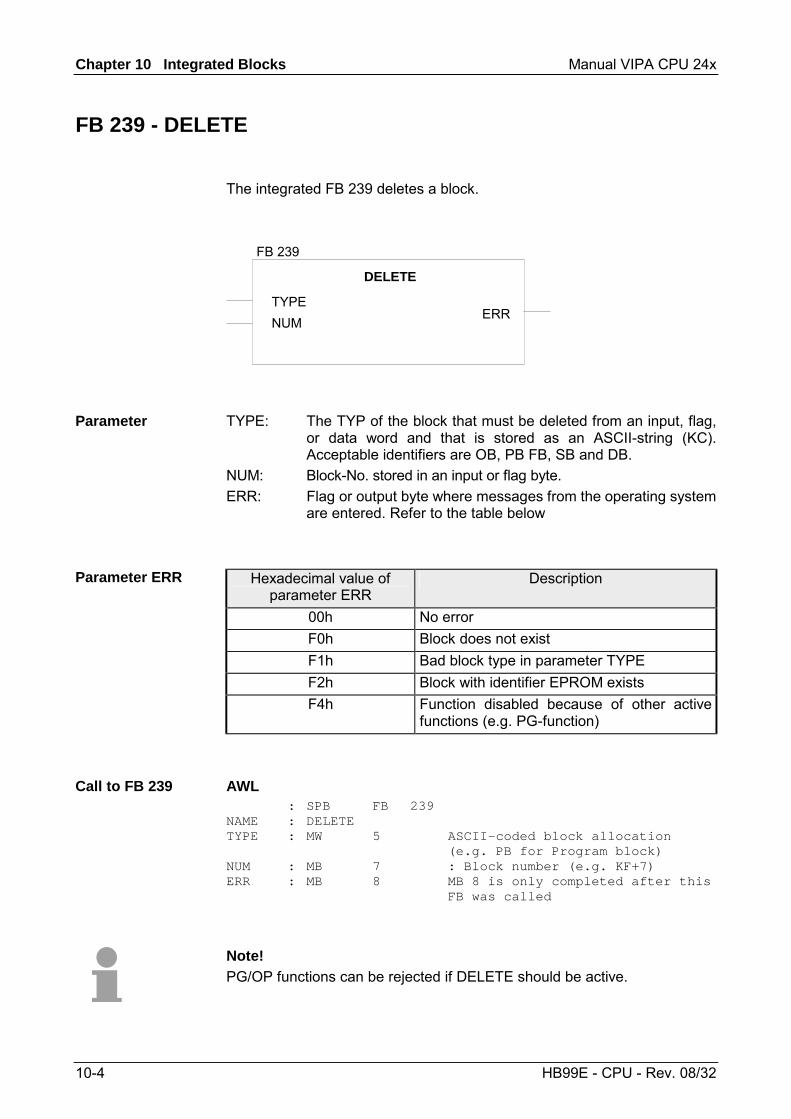
Chapter 10 Integrated Blocks Manual VIPA CPU 24x
10-4 HB99E - CPU - Rev. 08/32
FB 239 - DELETE
The integrated FB 239 deletes a block.
TYPENUM
ERR
FB 239
DELETE
TYPE: The TYP of the block that must be deleted from an input, flag, or data word and that is stored as an ASCII-string (KC). Acceptable identifiers are OB, PB FB, SB and DB.
NUM: Block-No. stored in an input or flag byte. ERR: Flag or output byte where messages from the operating system
are entered. Refer to the table below
Hexadecimal value of parameter ERR
Description
00h No error F0h Block does not exist F1h Bad block type in parameter TYPE F2h Block with identifier EPROM exists F4h Function disabled because of other active
functions (e.g. PG-function)
AWL : SPB FB 239 NAME : DELETE TYPE : MW 5 ASCII-coded block allocation
(e.g. PB for Program block) NUM : MB 7 : Block number (e.g. KF+7) ERR : MB 8 MB 8 is only completed after this
FB was called
Note! PG/OP functions can be rejected if DELETE should be active.
Parameter
Parameter ERR
Call to FB 239
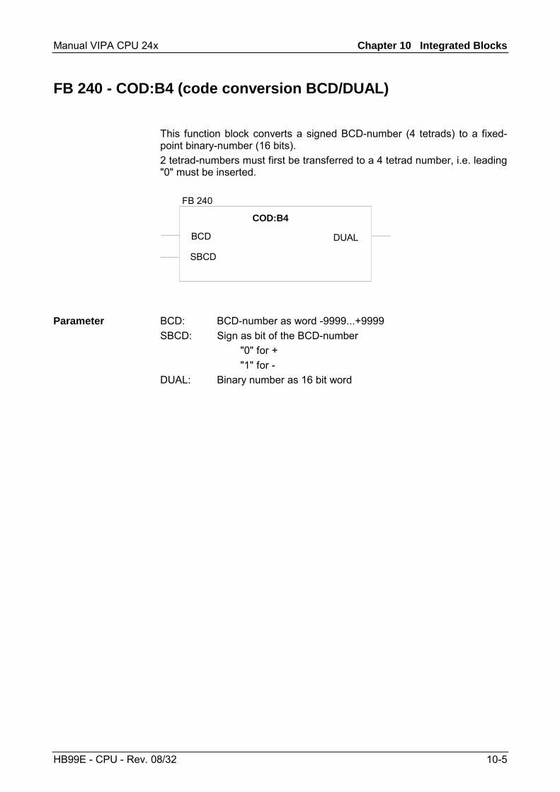
Manual VIPA CPU 24x Chapter 10 Integrated Blocks
HB99E - CPU - Rev. 08/32 10-5
FB 240 - COD:B4 (code conversion BCD/DUAL)
This function block converts a signed BCD-number (4 tetrads) to a fixed-point binary-number (16 bits). 2 tetrad-numbers must first be transferred to a 4 tetrad number, i.e. leading "0" must be inserted.
BCD DUAL
FB 240
COD:B4
SBCD
BCD: BCD-number as word -9999...+9999 SBCD: Sign as bit of the BCD-number
"0" for + "1" for -
DUAL: Binary number as 16 bit word
Parameter
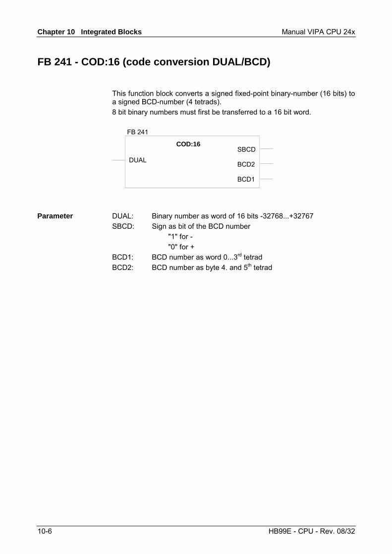
Chapter 10 Integrated Blocks Manual VIPA CPU 24x
10-6 HB99E - CPU - Rev. 08/32
FB 241 - COD:16 (code conversion DUAL/BCD)
This function block converts a signed fixed-point binary-number (16 bits) to a signed BCD-number (4 tetrads). 8 bit binary numbers must first be transferred to a 16 bit word.
DUAL
FB 241
COD:16SBCD
BCD2
BCD1
DUAL: Binary number as word of 16 bits -32768...+32767 SBCD: Sign as bit of the BCD number
"1" for - "0" for +
BCD1: BCD number as word 0...3rd tetrad BCD2: BCD number as byte 4. and 5th tetrad
Parameter

Manual VIPA CPU 24x Chapter 10 Integrated Blocks
HB99E - CPU - Rev. 08/32 10-7
FB 242 - MUL:16 (Multiplier)
This function block multiplies two fixed point binary numbers (16 bits). The product is returned in two fixed point binary numbers (16 bits each). The result is tested whether it is zero. Before multiplication, 8 bit numbers must be transferred into 16 bit words.
Z1
FB 242
MUL:16Z3=0
Z32
Z31Z2
Z1: Multiplier as word -32768...+32767 Z2: Multiplicand as word -32768...+32767 Z3=0: Test for 0; returns "1" if the product is zero Z32: Product high-word - 16 bits Z31: Product low-Word - 16 bits
Parameter
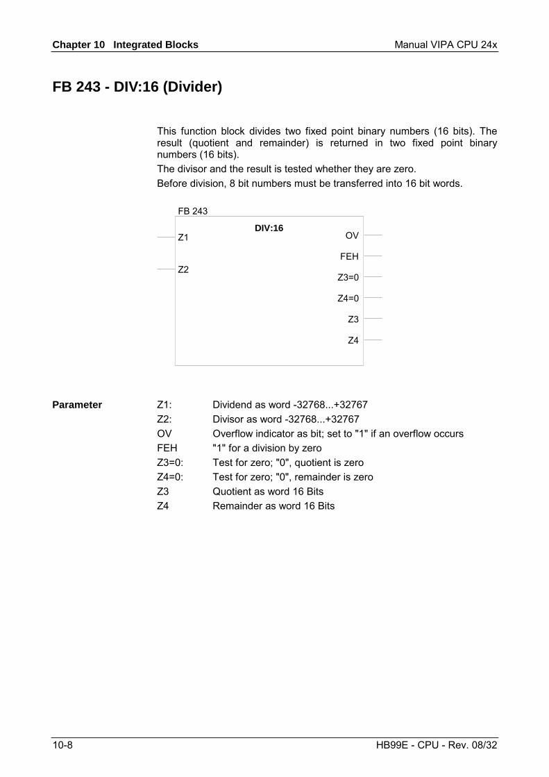
Chapter 10 Integrated Blocks Manual VIPA CPU 24x
10-8 HB99E - CPU - Rev. 08/32
FB 243 - DIV:16 (Divider)
This function block divides two fixed point binary numbers (16 bits). The result (quotient and remainder) is returned in two fixed point binary numbers (16 bits). The divisor and the result is tested whether they are zero. Before division, 8 bit numbers must be transferred into 16 bit words.
Z1
FB 243
DIV:16OV
FEH
Z3=0Z2
Z4=0
Z3
Z4
Z1: Dividend as word -32768...+32767 Z2: Divisor as word -32768...+32767 OV Overflow indicator as bit; set to "1" if an overflow occurs FEH "1" for a division by zero Z3=0: Test for zero; "0", quotient is zero Z4=0: Test for zero; "0", remainder is zero Z3 Quotient as word 16 Bits Z4 Remainder as word 16 Bits
Parameter
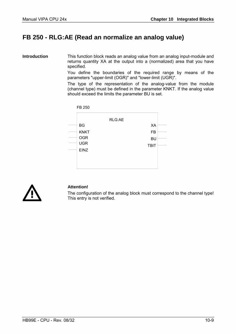
Manual VIPA CPU 24x Chapter 10 Integrated Blocks
HB99E - CPU - Rev. 08/32 10-9
FB 250 - RLG:AE (Read an normalize an analog value)
This function block reads an analog value from an analog input-module and returns quantity XA at the output into a (normalized) area that you have specified. You define the boundaries of the required range by means of the parameters "upper-limit (OGR)" and "lower-limit (UGR)". The type of the representation of the analog-value from the module (channel type) must be defined in the parameter KNKT. If the analog value should exceed the limits the parameter BU is set.
Attention! The configuration of the analog block must correspond to the channel type! This entry is not verified.
Introduction
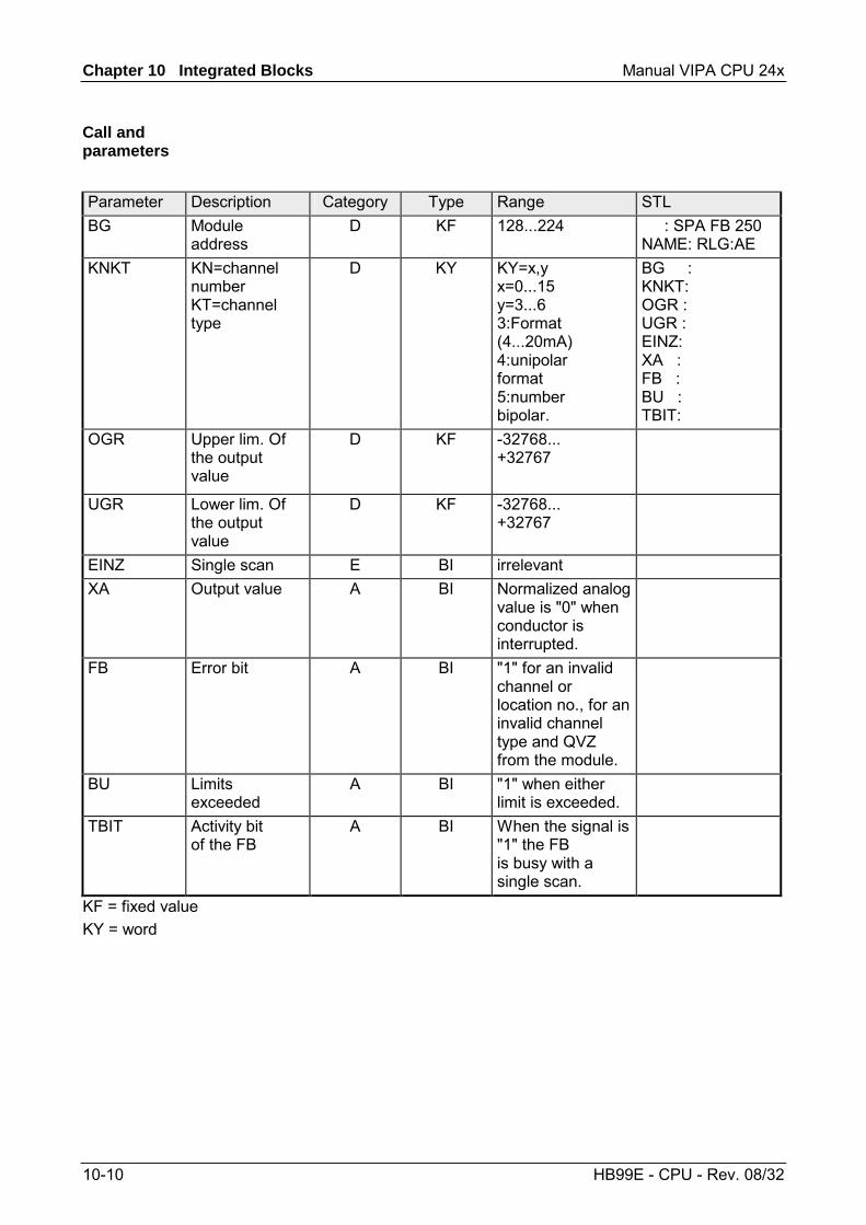
Chapter 10 Integrated Blocks Manual VIPA CPU 24x
10-10 HB99E - CPU - Rev. 08/32
Parameter Description Category Type Range STL BG Module
address D KF 128...224 : SPA FB 250
NAME: RLG:AE KNKT KN=channel
number KT=channel type
D KY KY=x,y x=0...15 y=3...6 3:Format (4...20mA) 4:unipolar format 5:number bipolar.
BG : KNKT: OGR : UGR : EINZ: XA : FB : BU : TBIT:
OGR Upper lim. Of the output value
D KF -32768... +32767
UGR Lower lim. Of the output value
D KF -32768... +32767
EINZ Single scan E BI irrelevant XA Output value A BI Normalized analog
value is "0" when conductor is interrupted.
FB Error bit A BI "1" for an invalid channel or location no., for an invalid channel type and QVZ from the module.
BU Limits exceeded
A BI "1" when either limit is exceeded.
TBIT Activity bit of the FB
A BI When the signal is "1" the FB is busy with a single scan.
KF = fixed value KY = word
Call and parameters

Manual VIPA CPU 24x Chapter 10 Integrated Blocks
HB99E - CPU - Rev. 08/32 10-11
Function block FB 250 performs a linear conversion of the input value in accordance with the specified upper and low limits (OGR and UGR) by means of the following formulas: for channel type 3 (range: 4 to 20mA):
XAUGR xe OGR xe
=⋅ − + ⋅ −( ) ( )2560 512
2048
for channel type 4 (unipolar representation):
XAUGR xe OGR xe
=⋅ − + ⋅( ) )2048
2048
channel type 5 and 6 (bipolar representation):
XAUGR xe OGR xe
=⋅ − + ⋅ −( ) ( )2048 2048
4096
where: XA is the value at the output of the FB xe is the analog input value at the module
Nominal rangeof module
standardized area
OGR (U-Lim)
XA
Analog qty.
UGR (L-Lim)
xe
Normalizing scheme

Chapter 10 Integrated Blocks Manual VIPA CPU 24x
10-12 HB99E - CPU - Rev. 08/32
FB 251 - RLG:AA (Analog value output)
This function block can be used to transfer analog values to the analog output-modules. The type of analog value-representation for the module (channel type) must be defined in parameter KNKT. The values located between the parameters "lower limit (UGR)" and "upper limit (OGR)" are converted to the nominal range of the respective module in accordance with the following formulas: for channel type 0 (unipolar representation):
xaXE UGR
OGR UGR=
⋅ −−
1024 ( )
for channel type 1 (bipolar representation):
xaXE OGR UGR
OGR UGR=
⋅ ⋅ − −−
1024 2( )
where: XE is the digital value at the function block xa is the value that is transferred to the module
Normalizing

Manual VIPA CPU 24x Chapter 10 Integrated Blocks
HB99E - CPU - Rev. 08/32 10-13
Parameter Description Category Type Range STL XE Analog output
value E W Input value
(fixed point) in the range UGR...OGR
BG Module address
D KF 128...240 : SPA FB 250 NAME: RLG:AE
KNKT KN=channel number KT=channel type
D KY KY=x,y x=0...7 y=0;1;2 0: unipolar representation 1:fixed point number bipolar 2: Range (4...20mA or 1,5V )
BG : KNKT: OGR : UGR : EINZ: XA : FB : BU : TBIT:
OGR Upper limit of the output value
D KF -32768... +32767
UGR Lower limit of the output value
D KF -32768... +32767
FEH Error during limit definition
A BI Is "1" if UGR=OGR, for a bad channel no. or plug-in location or for QVZ from the module.
BU Analog output value exceeds UGR or OGR
A BI If "1" then XE exceeds (UGR;OGR) XE is set to limit value.
Call and configuration
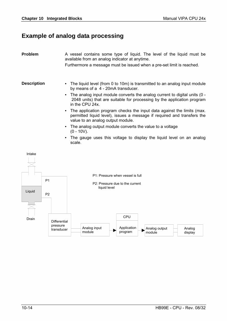
Chapter 10 Integrated Blocks Manual VIPA CPU 24x
10-14 HB99E - CPU - Rev. 08/32
Example of analog data processing
A vessel contains some type of liquid. The level of the liquid must be available from an analog indicator at anytime. Furthermore a message must be issued when a pre-set limit is reached.
• The liquid level (from 0 to 10m) is transmitted to an analog input module by means of a 4 - 20mA transducer.
• The analog input module converts the analog current to digital units (0 - 2048 units) that are suitable for processing by the application program in the CPU 24x.
• The application program checks the input data against the limits (max. permitted liquid level), issues a message if required and transfers the value to an analog output module.
• The analog output module converts the value to a voltage (0 - 10V).
• The gauge uses this voltage to display the liquid level on an analog scale.
Intake
Differentialpressuretransducer Analog input
module
CPU
Applicationprogram
Analog-Ausgabe-baugruppe
Analogdisplay
Analog outputmodule
Drain
P1
P2
P1: Pressure when vessel is full
P2: Pressure due to the current liquid level
Liquid
Problem
Description
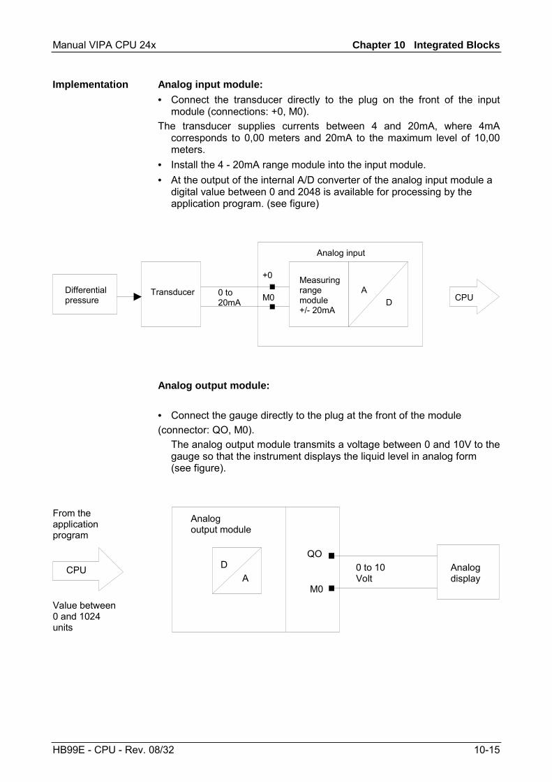
Manual VIPA CPU 24x Chapter 10 Integrated Blocks
HB99E - CPU - Rev. 08/32 10-15
Analog input module: • Connect the transducer directly to the plug on the front of the input
module (connections: +0, M0). The transducer supplies currents between 4 and 20mA, where 4mA
corresponds to 0,00 meters and 20mA to the maximum level of 10,00 meters.
• Install the 4 - 20mA range module into the input module. • At the output of the internal A/D converter of the analog input module a
digital value between 0 and 2048 is available for processing by the application program. (see figure)
Measuringrangemodule+/- 20mA
Differentialpressure
Transducer 0 to 20mA
+0
M0A
D CPU
Analog input
Analog output module: • Connect the gauge directly to the plug at the front of the module (connector: QO, M0).
The analog output module transmits a voltage between 0 and 10V to the gauge so that the instrument displays the liquid level in analog form (see figure).
CPU DA
From theapplicationprogram
Value between0 and 1024units
Analogoutput module
QO
M0
0 to 10Volt
Analogdisplay
Implementation
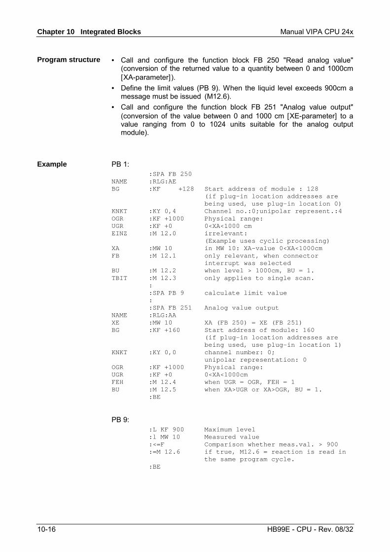
Chapter 10 Integrated Blocks Manual VIPA CPU 24x
10-16 HB99E - CPU - Rev. 08/32
• Call and configure the function block FB 250 "Read analog value" (conversion of the returned value to a quantity between 0 and 1000cm [XA-parameter]).
• Define the limit values (PB 9). When the liquid level exceeds 900cm a message must be issued (M12.6).
• Call and configure the function block FB 251 "Analog value output" (conversion of the value between 0 and 1000 cm [XE-parameter] to a value ranging from 0 to 1024 units suitable for the analog output module).
PB 1: :SPA FB 250 NAME :RLG:AE BG :KF +128 Start address of module : 128 (if plug-in location addresses are being used, use plug-in location 0) KNKT :KY 0,4 Channel no.:0;unipolar represent.:4 OGR :KF +1000 Physical range: UGR :KF +0 0<XA<1000 cm EINZ :M 12.0 irrelevant: (Example uses cyclic processing) XA :MW 10 in MW 10: XA-value 0<XA<1000cm FB :M 12.1 only relevant, when connector interrupt was selected BU :M 12.2 when level > 1000cm, BU = 1. TBIT :M 12.3 only applies to single scan. : :SPA PB 9 calculate limit value : :SPA FB 251 Analog value output NAME :RLG:AA XE :MW 10 XA (FB 250) = XE (FB 251) BG :KF +160 Start address of module: 160 (if plug-in location addresses are being used, use plug-in location 1) KNKT :KY 0,0 channel number: 0; unipolar representation: 0 OGR :KF +1000 Physical range: UGR :KF +0 0<XA<1000cm FEH :M 12.4 when UGR = OGR, FEH = 1 BU :M 12.5 when XA>UGR or XA>OGR, BU = 1. :BE PB 9: :L KF 900 Maximum level :l MW 10 Measured value :<=F Comparison whether meas.val. > 900 :=M 12.6 if true, M12.6 = reaction is read in the same program cycle. :BE
Program structure
Example
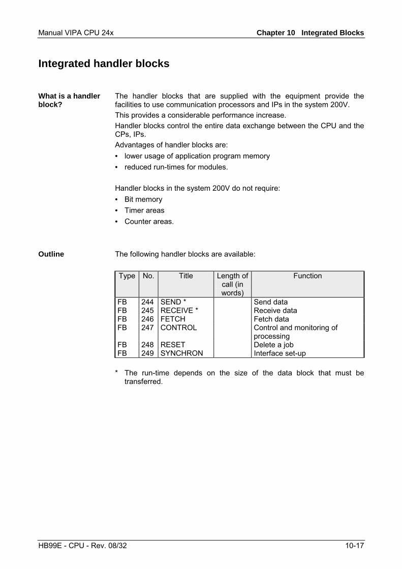
Manual VIPA CPU 24x Chapter 10 Integrated Blocks
HB99E - CPU - Rev. 08/32 10-17
Integrated handler blocks
The handler blocks that are supplied with the equipment provide the facilities to use communication processors and IPs in the system 200V. This provides a considerable performance increase. Handler blocks control the entire data exchange between the CPU and the CPs, IPs. Advantages of handler blocks are: • lower usage of application program memory • reduced run-times for modules. Handler blocks in the system 200V do not require: • Bit memory • Timer areas • Counter areas.
The following handler blocks are available: Type No. Title Length of
call (in words)
Function
FB 244 SEND * Send data FB 245 RECEIVE * Receive data FB 246 FETCH Fetch data FB 247 CONTROL Control and monitoring of
processing FB 248 RESET Delete a job FB 249 SYNCHRON Interface set-up
* The run-time depends on the size of the data block that must be
transferred.
What is a handler block?
Outline
Chapter 10 Integrated Blocks Manual VIPA CPU 24x
10-18 HB99E - CPU - Rev. 08/32
The handler block parameters
All the handler blocks described below have a standardized interface with respect to the application program (see also parameter description). The parameters are: SSNR :interface number A-NR :job number ANZW :indicator word (double word) QTYP/ZTYP* :type of data source or destination DBNR* :data block number QANF/ZANF* :relative start address within the type QLAE/ZLAE* :number of source and destination data items PAFE :configuration error BLGR :block size *) Parameters that are not required for a certain job (e.g. for the "ALL-
function") can be skipped during configuration of the block by pressing "CR".
A handler block can be configured directly or indirectly. Parameter "PAFE" must always be specified directly. During direct configuration the handler block processes parameters specified in the call to the block directly. During indirect configuration block parameters are passed to the handler block by means of block parameter pointers that contain the address (data block or data word) of the respective parameter field.
direct/indirect configuration

Manual VIPA CPU 24x Chapter 10 Integrated Blocks
HB99E - CPU - Rev. 08/32 10-19
Parameter description of the handler blocks
Interface number The number of the logical interface (page frame address) related to the respective job. Parameter type : data byte (format KY) Useful range : 0,0...0,255 (for direct configuration) * *) If the left hand byte >0 this is an indirect configuration of SSNR,
A-NR; ANZW or BLGR. In this case the right hand byte represents the pointer to the parameter field (see example: indirect configuration).
Job number
The job number for the logical interface Parameter type : data byte (format KY) Useful range : 0,0...0,223 In this case the job number 0 has the special function "ALL" that is not permitted for the FETCH block (see also the example for the ALL function).
Indicator word (double word)
Address of the indicator double word in application memory where the progress of the job specified under A-NR is displayed. Parameter type : address word Permitted range : DW or MW occupies DW and DW+1 or MW and MW+2 The DW identifier refers to the data block that was rejected by the call. Structure of ANZW: see Indicator word structure.
Type of data source or data destination
This parameter specifies the type of the data source (SEND) or the data destination (RECEIVE and FETCH) by means of an ASCII string. Parameter type :data character (format KC) Useful range :DB, MB, AB, EB, ZB, TB, AS, NN, XX, RW
Data block number for TYP XX, RW, DB
If you have specified the identifier XX, RW or DB for QTYP/ZTYP, the number of the required data block must be entered for this parameter. Parameter type : data byte (format KY) Useful range : 0,1...0,255
SSNR
A-NR
ANZW
QTYP/ZTYP
DBNR
Chapter 10 Integrated Blocks Manual VIPA CPU 24x
10-20 HB99E - CPU - Rev. 08/32
Start address of the source/destination data block This is where the DW-number is entered where the parameters start for type identifiers XX and RW (indirect configuration). Otherwise this parameter refers to the specified range in absolute form. Parameter type : data fixed-point (format KF) Possible range : 0...+32767 or up to -32768 for "AS"
Length of the source/destination data block
Specifies the length in bytes or words, depending on the type of the source/destination. Parameter type : data fixed point number (format KF) Possible range : 0...+32767 (-1)* *) The default length (QLAE, ZLAE (-1)) during RECEIVE means
that as much data is accepted as can be supplied by the sender or up to the limit. During a SEND this means that as much data is transferred as can be accepted by the area.
Block size
After a reboot the handler block "SYNCHRON" negotiates the block size (number of data blocks) that is used between the stations. In this case a large block size means = higher data throughput but long run-times and therefore higher cycle times. Small block size = lower data throughput but reduced runtimes for the blocks. Parameter type : data byte (format KY) Possible range : 0,0 ...0,255 (see definable block size)
Error indicator for configuration errors The "BYTE" (output, flags) that is specified in this area is set when the block recognizes a "configuration error", e.g. interface (connector) does not exist not existing or bad configuration of QTYP/ZTYP; QANF/ZANF;QALAE/ZLAE. Parameter type : output, byte Useful range : AB 0... AB 63 for CPU 241; AB 0 ... AB127
for CPU 242 : MB 0...MB 255
QANF/ZANF
QLAE/ZLAE
BLGR
PAFE
Manual VIPA CPU 24x Chapter 10 Integrated Blocks
HB99E - CPU - Rev. 08/32 10-21
Configuration of SSNR, A-NR, ANZW and BLGR
The HIGH-Byte of the parameter SSNR is used as the change-over criterion for direct or indirect configuration. • HIGH-Byte of SSNR = 0 means direct configuration
SSNR, A-NR, ANZW or BLGR are defined directly in the block. • HIGH-Byte of SSNR ><0 means indirect configuration
SSNR, A-NR and ANZW/BLGR are available from the opened DB starting from the LOW-Byte of the data word in SSNR.
SSNR and A-NRS have the same data format in both types of configuration (KY). The types of representation for indicator word ANZW are different. While the address of the indicator word (e.g. MW 100) is specified directly during direct configuration, an additional specification on the range of the indicator word must be included when you are using indirect configuration. The specification for this area are contained in ASCII coded form in the data word that precedes the indicator word. Here: MW means indicator word is flag area, DB refers to indicator word in the data block. The data word of the parameter area that follows in the DB contains the ANZW address in data format KY, for the DB this includes the block number (the first byte of the KY format). Example: Direct configuration of SSNR, A-NR and ANZW (ANZW = MW) SPA FB245 NAME :RECEIVE SSNR :KY 0,3 ;Parameter SSNR =3 A-NR :KY 0,100 ;Parameter A-NR = Job NR 100 ANZW :MW 240 ;Parameter ANZW = MW 240 . .

Chapter 10 Integrated Blocks Manual VIPA CPU 24x
10-22 HB99E - CPU - Rev. 08/32
(ANZW = DW) A DB X . . SPA FB247 NAME :CONTROL SSNR :KY 0,3 ;Parameter SSNR = 3 A-NR :KY 0,100 ;Parameter A-NR = NR 100 ANZW :DW 40 ;Parameter ANZW =DW 40 in DB X . . DB X DW 40 DW 41 Indirect configuration of SSNR, A-NR and ANZW (Typ MW) A DB X ;Open the data block "X" SPA FB244 NAME :SEND SSNR :KY 255,1 Identifier indirect configuration ;Interpreted as pointer A-NR :KY 0,0 ;Irrelevant ANZW :MW 0 ;Irrelevant . . DB X DW 1 KY 0,1 ;Parameter SSNR (=1) DW 2 KY 0,31 ;Parameter A-NR (31) DW 3 KC MW Parameter type for ANZW (=MW) DW 4 KY 0,200 Address of the Parameter ANZW (MW 200 and MW 202)
Manual VIPA CPU 24x Chapter 10 Integrated Blocks
HB99E - CPU - Rev. 08/32 10-23
Indirect configuration of SSNR, A-NR and ANZW (Typ DW) . . A DB X ;Open data block "X" SPA FB244 NAME :SEND SSNR :KY 255,1 ; Identifier indirect configuration ;Interpreted as pointer A-NR :KY 0,0 ;Irrelevant ANZW :MW 0 ;Irrelevant . . DB X DW 1 KY 0,1 ;Parameter SSNR (=1) DW 2 KY 0,31 ;Parameter A-NR (=31) DW 3 KC DB ;Parameter type for ANZW (=DW) DW 4 KY 222,10 ;Addr. of ANZW (in DB 222 DW 10 + DW11) DB 222 DW 10 ; DW 11 ; ANZW Indirect configuration of SSNR and BLGR (SYNCHRON) A DB X Open the DB SPA FB249 NAME SYNCHR SSNR :KY 255, 100 ;Pointer to parameter list BLGR :KY 0,0 ;Irrelevant . : DB X DW 100 KY 0,16 ;Parameter SSNR DW 101 KY 0,6 ;BLGR
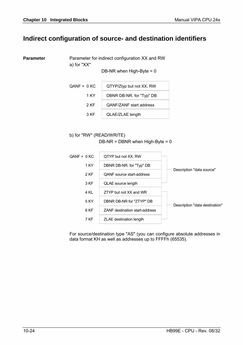
Chapter 10 Integrated Blocks Manual VIPA CPU 24x
10-24 HB99E - CPU - Rev. 08/32
Indirect configuration of source- and destination identifiers
Parameter for indirect configuration XX and RW a) for "XX" DB-NR when High-Byte = 0
QTYP/Ztyp but not XX, RW
DBNR DB-NR. for "Typ" DB
QANF/ZANF start address
QLAE/ZLAE length
QANF + 0 KC
1 KY
2 KF
3 KF b) for "RW" (READ/WRITE) DB-NR = DBNR when High-Byte = 0
QTYP but not XX, RW
DBNR DB-NR. for "Typ" DB
QANF source start-address
QLAE source length
ZTYP but not XX and WR
DBNR DB-NR for "ZTYP" DB
ZANF destination start-address
ZLAE destination length
QANF + 0 KC
1 KY
2 KF
3 KF
4 KL
5 KY
6 KF
7 KF
Description "data source"
Description "data destination"
For source/destination type "AS" (you can configure absolute addresses in data format KH as well as addresses up to FFFFh (65535).
Parameter

Manual VIPA CPU 24x Chapter 10 Integrated Blocks
HB99E - CPU - Rev. 08/32 10-25
Table of the possible QTYP/ZTYP parameters
QTYP/ZTYP Description
NN XX RW DB MB AB
No source/Destination parameters at the block; parameters must be available on the CP.
Indirect Addressing. Parameters are stored in the DB (by means of DBNR and QANF spec.).
Indirect Addressing without data exchange; Source/ Destination parameters are stored in a DB.
Source/destination-data from/into DB in main memory.
Source/destination-data from/into flag area.
Source/destination-data from/into process image of the outputs (PAA).
DBNR significance
irrelevant DB where the source /destination parameters have been stored.
DB where the source /destination parameters have been stored.
DB, where the source data is available or where the destination data must be stored.
irrelevant irrelevant
permitted range 2...255 2...255 2...255 QANF/ ZANF significance
irrelevant DW-No., from which the para-meters have been stored.
DW-No., from which the para-meters have been stored.
DW-No., from where the data should be retrieved or where the data must be stored.
Flag byte-No. from where the data must be retrieved or where the data must be stored.
Output byte-No., from where the data must be retrieved or where the data must be stored.
permitted range 0...2047 0....2047 0...2047 0...255 0...127 QLAE/ ZLAE significance permitted range
irrelevant irrelevant irrelevant Length of the source/destination data block in words. 1...2048
Length of the source/destination data block in bytes. 1...255
Length of the source/destination data block in bytes. 1...128
continued ...

Chapter 10 Integrated Blocks Manual VIPA CPU 24x
10-26 HB99E - CPU - Rev. 08/32
... continue QTYP/ ZTYP Description
EB PB ZB TB AS
Source/destination data from/into process-image of the inputs (PAE).
Source/destination data from/into peripheral modules. Input module for source data, output module for destination data.
Source/destination data from/into counter cell.
Source/destination data from/into timer cells.
Source/destination data from/into absolute addressed memory cells.
DBNR Significance
irrelevant irrelevant irrelevant irrelevant irrelevant
QANF/ ZANF Significance
Input byte-No. from where the data is retrieved or where it is stored.
Peripheral byte-No. from where the data is retrieved or where it is stored.
Number of the counter cell, from where the data is retrieved or where it is stored.
Number of the timer cell, from where the data is retrieved or where it is stored.
absolute start address, from where the data is retrieved or where it is stored.
Permitted range
0...127 0...127 digit. Peripher.127...255 anal. Peripher.
0...127 0...127 0...+32767 -32768
QLAE/ ZLAE Significance
Length of the Source/destination-data block in bytes.
Length of the Source/destination-data block in bytes.
Length of the Source/destination-data block in words (counter cell = 1 word).
Length of the Source/destination-data block in words (timer cell = 1 word).
Length of the Source/destination-data block in words.
Permitted range
1...128 1...256 1...128 1..128 1...32767

Manual VIPA CPU 24x Chapter 10 Integrated Blocks
HB99E - CPU - Rev. 08/32 10-27
Indicator word structure
Status and error indicators are generated by the Handler blocks: • via the indicator word ANZW (information on the processing of jobs), • via the configuration error byte PAFE (indicator for a bad configuration of
the job). The basic structure of the indicator word is as follows:
7 6 5 4 3 2 1 0
bit-no.
Status administration (of CP)
Handshake meaningful
Job active
Job completed without errors
Job completed with errors
Data administration (by handler block)
Data reception/transmission active
Data transmission completed
Data reception completed
Disable/Enable data block
7 6 5 4 3 2 1 0
bit-no.
Error behaviorreserved
7 6 5 4 3 2 1 0
bit-no.
Length word
7 6 5 4 3 2 1 0
bit-no.
Length word
Byte 1
Byte 2
Byte 3
Byte 4
(from handler block)
(from handler block)
(from CP)
Status and error indicators
Contents and structure of indicator word ANZW
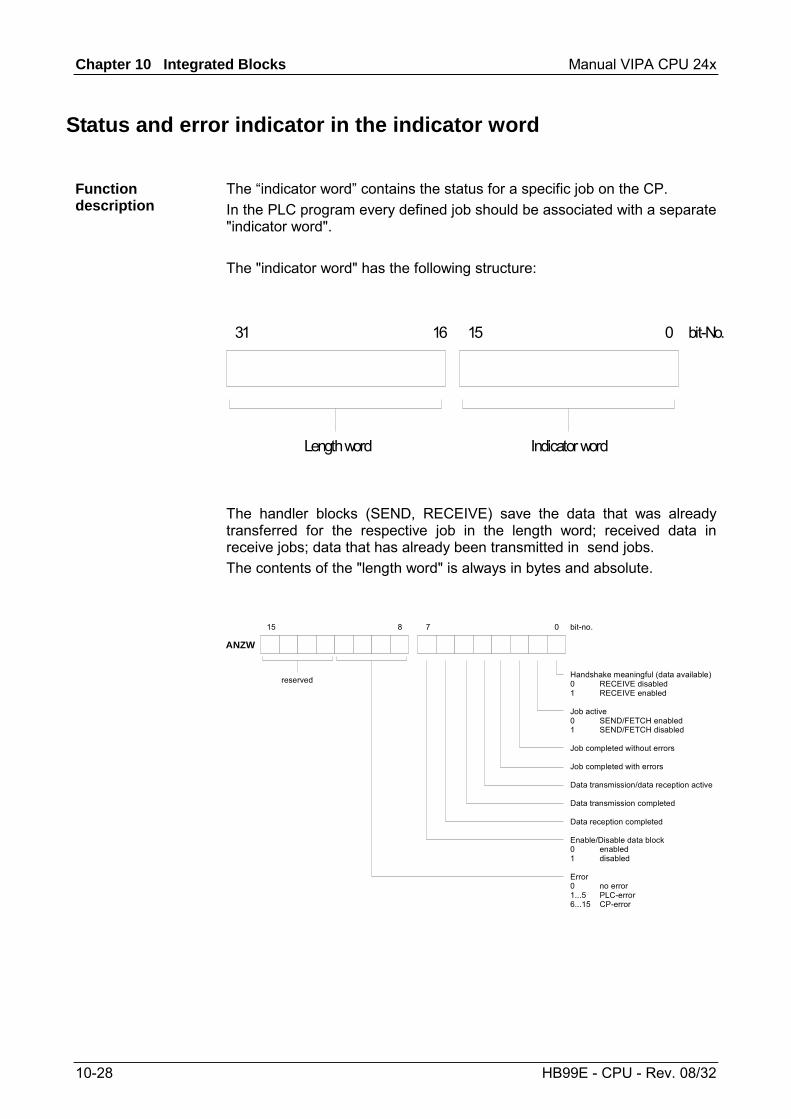
Chapter 10 Integrated Blocks Manual VIPA CPU 24x
10-28 HB99E - CPU - Rev. 08/32
Status and error indicator in the indicator word
The “indicator word” contains the status for a specific job on the CP. In the PLC program every defined job should be associated with a separate "indicator word". The "indicator word" has the following structure:
Length word Indicator word
15 0 bit-No.31 16
The handler blocks (SEND, RECEIVE) save the data that was already transferred for the respective job in the length word; received data in receive jobs; data that has already been transmitted in send jobs. The contents of the "length word" is always in bytes and absolute.
7 0 bit-no.
Handshake meaningful (data available) 0 RECEIVE disabled 1 RECEIVE enabled Job active 0 SEND/FETCH enabled 1 SEND/FETCH disabled
Job completed without errors
Job completed with errors
Data transmission/data reception active
Data transmission completed
Data reception completed
Enable/Disable data block 0 enabled1 disabled
Error0 no error1...5 PLC-error6...15 CP-error
15 8
ANZW
reserved
Function description

Manual VIPA CPU 24x Chapter 10 Integrated Blocks
HB99E - CPU - Rev. 08/32 10-29
Indicator word
Handshake meaningful Set: by the interface, in accordance with the "delete" indicator
in the job status bit. Handshake meaningful (=1) is used with the RECEIVE-block. (message available with PRIO 1 or RECEIVE triggering possible with PRIO 2/3)
Evaluation: by the RECEIVE-block: only if this bit is set does the RECEIVE handshake with the CP. By the application: For RECEIVE-requests (check whether a message is available for PRIO 1).
Job active Set: by the interface, when job was issued to the CP. Delete: by the interface, when a job has been completed (e.g.
acknowledgment received). Evaluation: by the Handler blocks: a new job is only issued when the
"old" job has been completed. By the user: to check whether it is possible to trigger a
new job.
Job completed without errors Set: by the interface, when the respective job was completed
without errors. Delete: by the interface, when the job is triggered again. Evaluation: by the user to check whether the job was completed
without errors.
Job completed with errors Set: by the interface, when the respective job was completed
with errors. The reason for the error is encoded in the high-portion of the indicator word.
Delete: by the interface, when the job is triggered again. Evaluation: by the user: to check whether the job was completed with
errors. If the identifier "Job completed with errors" is set the high byte of the indicator word contains the reason for the error.
Bit 0
Bit 1
Bit 2
Bit 3
Chapter 10 Integrated Blocks Manual VIPA CPU 24x
10-30 HB99E - CPU - Rev. 08/32
• Data administration byte 1, bit 4 to bit 7 This area contains the encoded instruction whether the data transfer for the job is still active or whether the data transfer as well as data reception has already been completed. The "Enable / Disable" bit can be used to inhibit data transfers for the job. (Disable = 1; Enable = 0).
Data reception / Data transfer active Set: by means of handler blocks SEND, RECEIVE, when the
transfer/reception was started for a job, e.g. if data is exchanged by means of the ALL function (DMA-replacement) but the action was triggered by means of SEND-DIREKT.
Delete: by means of handler blocks SEND, RECEIVE, if the data exchange has been completed for a job (last sub-block was transferred).
Evaluate: By the user: during CP << >> INC data-transfer the user must not change the record for the job. In PRIO 0/1 jobs this is not critical since the data transfer can be completed in a single cycle through the block. Larger quantities of data can, however, only be transferred in blocks. The respective blocks are distributed over several PLC cycles. To maintain data consistency it must be checked whether the data block is being transferred before its contents is altered.
Data transfer completed Set: by the handler block SEND when the data transfer for a
job has been completed. Delete: By handler block SEND the data transfer for a new job
(new trigger) was started . By the user: If the evaluation took place (edge
generation). Evaluate: By the user: this bit checks whether the record for a job
was already transferred to the CP or at what time a new record can be supplied for an active job (e.g. cyclic transfer).
Bit 4
BIT 5

Manual VIPA CPU 24x Chapter 10 Integrated Blocks
HB99E - CPU - Rev. 08/32 10-31
Data transfer completed Set: By the handler block RECEIVE, when the data transfer for
a job has been completed. Delete: By the handler block RECEIVE, when the data transfer to
the PLC was started for a new job. By the user, when the evaluation is being done (edge generation).
Evaluate: By the user: The user can use this bit to determine whether a data record of a job was already transferred to the PLC or not or when a new record for the active job was transferred into the PLC.
Disable / Enable data block Set: By the user, to prevent overwriting of a memory area by
the RECEIVE block or to prevent the SEND block from reading data from a memory area (only for the 1st data block).
Delete: By the user, to release the respective data blocks. Evaluate: By handler blocks SEND and RECEIVE. If bit 7 is set the
block will not start a data transfer but instead report an error to the CP.
• Error management byte 2, bit 0 to bit 3 This is where the error indicators of the job are stored. These error indicators are only valid if bit "Job completed with errors" in the status bit was set simultaneously. The following error messages can be displayed: 0 no error If the bit “Job completed with errors” is set the CP143
H1 / TCP/IP was forced to re-establish the communication link, e.g. after a reboot or a RESET.
1 bad Q/ZTYP at the HTB The job was configured with an incorrect TYP-identifier 2 Area does not exist in the PLC The job was started with a bad DB (DBNR). 3 Area in PLC too small The sum of Q/ZANF and Q/ZLAE exceeds the boundaries of the area.
The boundaries for data blocks are determined by the block size. In case of flags, timers, counters etc. the area size depends on the PLC.
Bit 6
Bit 7
Chapter 10 Integrated Blocks Manual VIPA CPU 24x
10-32 HB99E - CPU - Rev. 08/32
4 QVZ-error in the PLC The source - or destination parameter define an area in the PLC whose
memory is defective or where memory was not installed. The QVZ-error can only appear for Q/ZTYP AS, PB, QB or when memory faults occur.
5 Indicator word errors The specified indicator word cannot be processed. This error occurs if a
data word as well as a double word were specified with ANZW and the respective words are not yet or no longer available in the specified data block, i.e. DB too small or it does not exist.
6 no valid ORG-format The destination or source for the data was not specified in the handle
block (Q/TYP="NN") or in the connection block. 7 Reserved 8 no unused transport connections The transport connection capacity was exceeded. Delete all
unnecessary connections. 9 Remote error An error occurred at the communication partner in a READ/WRITE job. A Connection error The connection required for a job does not exist. This error is cleared as
soon as a connection can be established. If all the connections of the CP have been are interrupted this indicates a defective module or bus cable. The error can also be caused by bad configuration, e.g. incorrect addressing.
B Handshake error This can be a system error or the data block size that was selected is
too high. C Triggering error An incorrect handler block was used to trigger the job or the transferred
data block was too large. D Termination after RESET This is an operational message. For priority 1 and 2 the connection was
interrupted and it is being re-established as soon as the communication partner is ready for a new connection. In case of priority 3 connections the connection was cleared, it can be re-triggered.
E Job with bootstrap function This is an operational message. The job is a READ/WRITE-PASSIV and
it can not be started from the PLC. F Job does not exist The requested job was not configured on the CP143 H1 / TCP/IP. This
error can occur when the SSNR/A-NR combination is entered incorrectly into the handler block or if a connection block was not entered.
Bits 4 to 7 of byte 2 are reserved for future expansion.
Manual VIPA CPU 24x Chapter 10 Integrated Blocks
HB99E - CPU - Rev. 08/32 10-33
Important status and error indicators of the CPU 24x NET The following section describes important status and error messages that can appear in the "indicator word". The representation makes use of "HEX"-patterns that you can also monitor by means of the Status / Control-Var-Test-function of the PG in the PLC. The X means "undefined" or "irrelevant"; No. is the error-number. Possible indicator words Indicator word: X F X A Error indicator ”F" shows that the respective job was not defined on the CP 143. Status indicator A inhibits the job (for SEND / FETCH and RECEIVE). Indicator word: X A X A Error indicator “A” shows that the connection for the communication task was not or not yet established. Status indicator "A" inhibits both SEND as well as RECEIVE and FETCH. Indicator word: X 0 X 8 The connection was re-established (e.g. after a CP-reboot), SEND is enabled (communication task SEND). Indicator word: X 0 X 9 The connection was re-established, RECEIVE is enabled. (communication task RECEIVE). Indicator word: X 0 2 4 SEND was processed without errors, the data was transferred. Indicator word: X 0 4 5 RECEIVE was processed without errors, the data was transferred into the PLC. Indicator word: X 0 X 2 The SEND-, RECEIVE-, READ- or WRITE job is active. In case of SEND the partner has not yet changed to RECEIVE mode. For RECEIVE the partner has not yet issued the SEND.
Status and error indicators
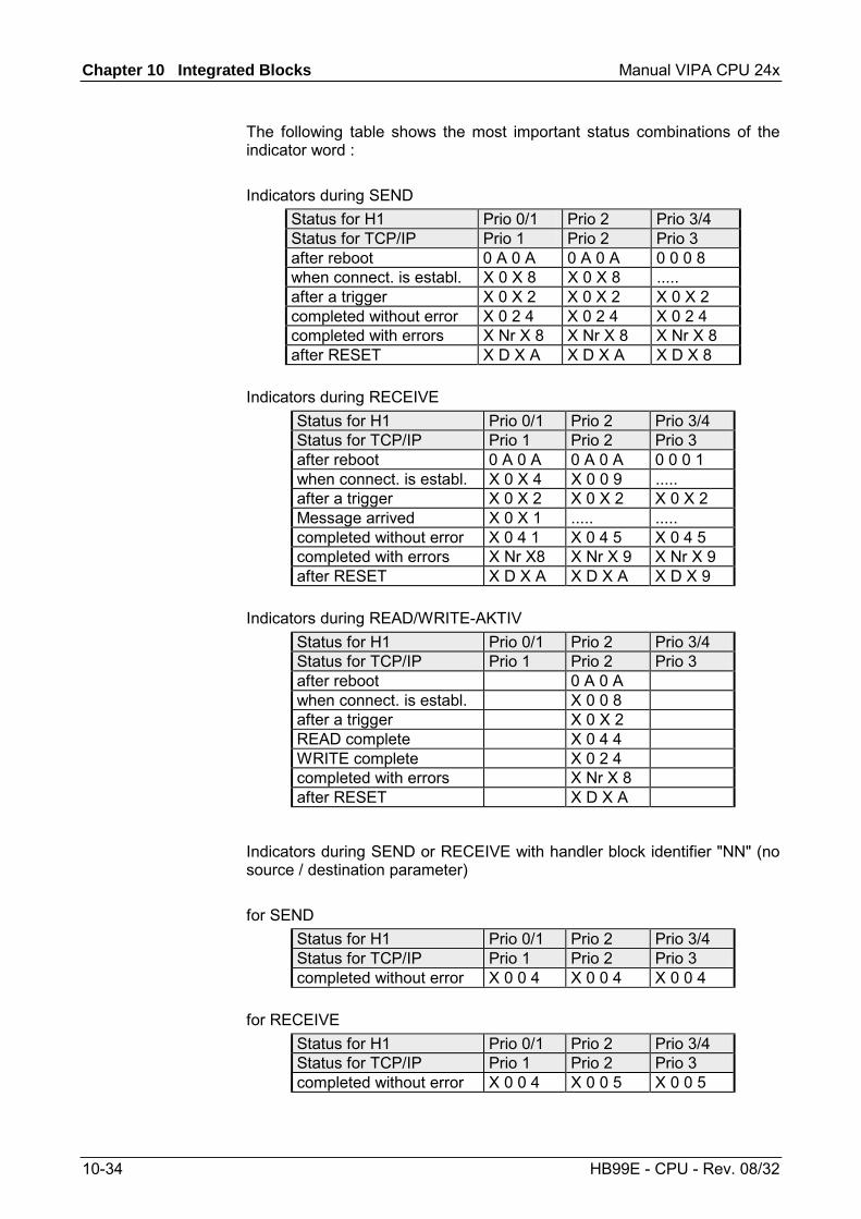
Chapter 10 Integrated Blocks Manual VIPA CPU 24x
10-34 HB99E - CPU - Rev. 08/32
The following table shows the most important status combinations of the indicator word : Indicators during SEND
Status for H1 Prio 0/1 Prio 2 Prio 3/4 Status for TCP/IP Prio 1 Prio 2 Prio 3 after reboot 0 A 0 A 0 A 0 A 0 0 0 8 when connect. is establ. X 0 X 8 X 0 X 8 ..... after a trigger X 0 X 2 X 0 X 2 X 0 X 2 completed without error X 0 2 4 X 0 2 4 X 0 2 4 completed with errors X Nr X 8 X Nr X 8 X Nr X 8 after RESET X D X A X D X A X D X 8
Indicators during RECEIVE
Status for H1 Prio 0/1 Prio 2 Prio 3/4 Status for TCP/IP Prio 1 Prio 2 Prio 3 after reboot 0 A 0 A 0 A 0 A 0 0 0 1 when connect. is establ. X 0 X 4 X 0 0 9 ..... after a trigger X 0 X 2 X 0 X 2 X 0 X 2 Message arrived X 0 X 1 ..... ..... completed without error X 0 4 1 X 0 4 5 X 0 4 5 completed with errors X Nr X8 X Nr X 9 X Nr X 9 after RESET X D X A X D X A X D X 9
Indicators during READ/WRITE-AKTIV
Status for H1 Prio 0/1 Prio 2 Prio 3/4 Status for TCP/IP Prio 1 Prio 2 Prio 3 after reboot 0 A 0 A when connect. is establ. X 0 0 8 after a trigger X 0 X 2 READ complete X 0 4 4 WRITE complete X 0 2 4 completed with errors X Nr X 8 after RESET X D X A
Indicators during SEND or RECEIVE with handler block identifier "NN" (no source / destination parameter) for SEND
Status for H1 Prio 0/1 Prio 2 Prio 3/4 Status for TCP/IP Prio 1 Prio 2 Prio 3 completed without error X 0 0 4 X 0 0 4 X 0 0 4
for RECEIVE
Status for H1 Prio 0/1 Prio 2 Prio 3/4 Status for TCP/IP Prio 1 Prio 2 Prio 3 completed without error X 0 0 4 X 0 0 5 X 0 0 5

Manual VIPA CPU 24x Chapter 10 Integrated Blocks
HB99E - CPU - Rev. 08/32 10-35
Length - Word
Length word Indicator word
15 0 bit-No.31 16
The handler block (SEND, RECEIVE) deposits the data that that it has transferred for the respective job in the length word; received data in receive jobs; transmitted data in send jobs. The entry in the "length word" is always in bytes and absolute. • Length word byte 3 and byte 4 The handler blocks (SEND, RECEIVE) deposit the quantity of data that has already been transferred for the respective job in the length word, i.e. for receive jobs the quantity that has already been received, for transmit jobs the quantity of data that has already been transmitted. Description: During the data exchange SEND, RECEIVE calculates
the "Length word" from: actual quantity transferred + quantity already
transferred Delete: By overwriting as well as with every new SEND,
RECEIVE, FETCH. When the bit "Job completed without errors" or "Data-transfer/reception completed" is set the "length word" contains the up to date source or destination length. If the bit "Job completed with error" is set then the length word contains the quantity of data that was transferred before the error occurred.
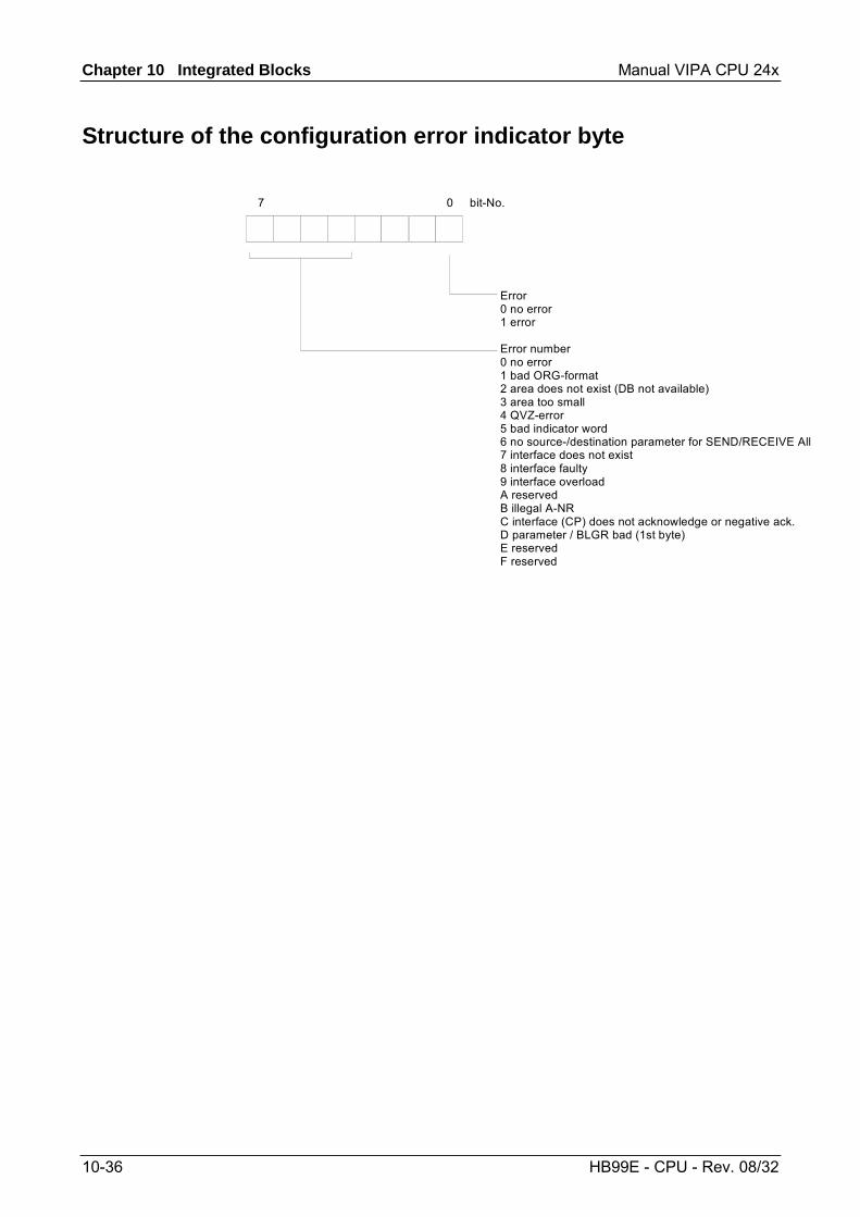
Chapter 10 Integrated Blocks Manual VIPA CPU 24x
10-36 HB99E - CPU - Rev. 08/32
Structure of the configuration error indicator byte
7 0 bit-No.
Error0 no error1 error
Error number0 no error1 bad ORG-format2 area does not exist (DB not available)3 area too small4 QVZ-error5 bad indicator word6 no source-/destination parameter for SEND/RECEIVE All7 interface does not exist8 interface faulty9 interface overloadA reservedB illegal A-NRC interface (CP) does not acknowledge or negative ack.D parameter / BLGR bad (1st byte)E reservedF reserved
Manual VIPA CPU 24x Chapter 10 Integrated Blocks
HB99E - CPU - Rev. 08/32 10-37
Adjustable block size
The following block sizes can be defined: 0 The block uses the default parameter (set to 64bytes on the CPU 24x) 1 Block size is 16Byte 2 Block size is 32Byte 3 Block size is 64Byte 4 Block size is 128Byte 5 Block size is 256Byte 6 Block size is 512Byte >6 and < 255 as for 0.
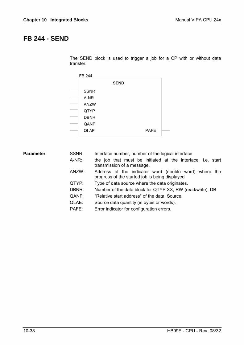
Chapter 10 Integrated Blocks Manual VIPA CPU 24x
10-38 HB99E - CPU - Rev. 08/32
FB 244 - SEND
The SEND block is used to trigger a job for a CP with or without data transfer.
SSNRA-NRANZWQTYPDBNRQANFQLAE PAFE
SEND
FB 244
SSNR: Interface number, number of the logical interface A-NR: the job that must be initiated at the interface, i.e. start
transmission of a message. ANZW: Address of the indicator word (double word) where the
progress of the started job is being displayed QTYP: Type of data source where the data originates. DBNR: Number of the data block for QTYP XX, RW (read/write), DB QANF: "Relative start address" of the data Source. QLAE: Source data quantity (in bytes or words). PAFE: Error indicator for configuration errors.
Parameter
Manual VIPA CPU 24x Chapter 10 Integrated Blocks
HB99E - CPU - Rev. 08/32 10-39
Description of the SEND-ALL-function For the SEND-ALL function (job number 0) the block only requires parameters: SSNR, A-NR = 0, ANZW and PAFE. All other parameters are irrelevant for this job. For the SEND-ALL-function the CP must supply the address of the indicator word, the specification of the data type, the quantity and the start address of the data in the communication area. In the indicator word, that is assigned to the relevant job the bits for "ENABLE/DISABLE", "Data transfer completed" as well as "Data-transfer active" can be tested or modified. The quantity of data for a job is displayed by SEND-ALL in the data or flag word following the ANZW. The block-indicator-word (indicator word, that was configured in the SEND-ALL-block) contains the current job number (0 means dummy run). The quantity of data that must be transferred for a job is displayed by SEND-ALL in the data word that follows after the indicator word. The SEND-ALL-function (i.e. the call to the send-block including the ALL-configuration) must be called at least once within a PLC-cycle for every interface when: • the CP can request data independently from a PLC. • a CP-job is initiated by a SEND-DIREKT, but the CP only requests the
data for this job via “background communications” from the PLC. • The quantity of data that is transferred to the CP with SEND-DIREKT is
larger than the specified block size. Description of the SEND-DIREKT function The block required the following parameters for the "DIREKT"-function: • interface number • job number >< 0 • specification of the indicator word • specification of the error byte "PAFE" • source type with DBNR • source start address • the quantity of source data. Normally the "SEND-DIREKT"-block is called from the cyclic portion of the application program. It is possible to include the block in the interrupt or watchdog section of the program, but the indicator word (ANZW) can not be updated cyclically in this case (it must be transferred by means of the CONTROL-block). For the data transfer and for the activation of the send trigger the connection to the CP is only established when: • FB was supplied with VKE "1". • the CP has enabled the job. (Bit "Job active" in ANZW =0). Only the indicator word is updated when the block is idle (when VKE "0" is transferred).
SEND-ALL
SEND-DIRECT

Chapter 10 Integrated Blocks Manual VIPA CPU 24x
10-40 HB99E - CPU - Rev. 08/32
If the QTYP-parameter contains identifier "NN" the source-parameters of the CP are used. If these parameters are also not available then the job is terminated with an error-message. If the CP can obtain on the data directly the SEND-block transfers the requested data in one process into the CP. However, if the CP signals that it only requires the parameters of the job or if the quantity of the data that must be transferred is too high only the parameters (QTYP/QLAE etc.) or the parameters of the first data block are transferred to the CP. The data or the subsequent blocks for these jobs is requested by the CP by means of the SEND ALL function from the PLC. For this purpose it is necessary that the SEND ALL block is called at least once in every PLC-cycle. The operator interface is same for all "triggering types", only the time of the data-transfer is postponed by at least one cycle for the last cases mentioned above.
Description of the WRITE-function Indirectly specified source and destination parameters are transferred to the CP during configuration with QTYP = "RW" using "SEND". In this case the destination parameters together with the user data (that were requested by means of SEND ALL) is transmitted to the communication partner ("WRITE"-function).
WRITE function

Manual VIPA CPU 24x Chapter 10 Integrated Blocks
HB99E - CPU - Rev. 08/32 10-41
FB 245 - RECEIVE
The RECEIVE-block requests the status of or starts a RECEIVE-job on a CP, with or without data transfer.
SSNRA-NRANZWZTYPDBNRZANFZLAE PAFE
FB 245
RECEIVE
SSNR: Interface number, number of the logical interface A-NR: RECEIVE-job of the interface, interrogation after a message
was received along with the data transfer. ANZW: Address of the indicator word (double word) where the
completion of the job is displayed. ZTYP: The type of data destination where the data should be stored. DBNR: Number of the DB for ZTYP XX, DB ZANF: "Relative start address" of the data destination ZLAE: Quantity of data that must be transferred. PAFE: Error indicator for configuration errors.
Parameter
Chapter 10 Integrated Blocks Manual VIPA CPU 24x
10-42 HB99E - CPU - Rev. 08/32
Description of the RECEIVE-ALL-function For the RECEIVE-ALL-function (job number " 0 ") the block only requires the interface number, the job number = 0, the output "PAFE" and the indicator word. All other parameters are irrelevant for this operating mode. For the RECEIVE ALL function the address of the indicator word, the specification of the type, the start address and the quantity of destination data is provided to the FB by the CP via the communication area. In the indicator word assigned to the job that must be processed, the bits "Enable/Disable", "Data transfer completed" as well as "Data transfer/read active" are tested or modified and the length of received data is stored in the next word. The current job number for which the RECEIVE ALL was active is saved in the block indicator word (configured indicator word of RECEIVE ALL). When RECEIVE ALL is idle the block indicator word id empty. The RECEIVE ALL (i.e. the RECEIVE-block with the ALL-configuration) must be called at least once per PLC-cycle when: • the CP must transfer data automatically to the PLC. • a data block that is larger than the defined block size must be received
by means of RECEIVE-DIREKT. The function block "RECEIVE-ALL" can be called by the user in: • the cyclic portion of the program (e.g. in OB 1), • the timer controlled portion of the program (e.g. watchdog block), • interrupt controlled program portion (process alarms).
The block requires the following parameters for the RECEIVE-DIRECT function: • SSNR interface number • A-NR job number ><0 • ANZW definition of the indicator word • PAFE specification of the error byte "PAFE" • ZTYP destination type possibly with DBNR • ZANF destination/start address • ZLAE quantity of data to be transferred Normally the RECEIVE-block is called in the cyclic portion of the application program. The program can also be included in the interrupt or watchdog portion of the program, however, in this case the indicator word is not updated cyclically. This must then be done by the CONTROL-block.
RECEIVE-ALL
RECEIVE-DIRECT
Manual VIPA CPU 24x Chapter 10 Integrated Blocks
HB99E - CPU - Rev. 08/32 10-43
The handshaking traffic with the CP (i.e. the triggering of a job) is only accepted by the RECEIVE block in the "DIREKT"-function when: • VKE "1" is transferred to the FB and • the CP has enabled the job. (bit "Handshake meaningful” = 1). Only the indicator word will be updated when the block is “idle”. The RECEIVE-(DIRECT)-block reacts differently, depending on the type of input and on the CP-reaction: • If the indicator "NN" is entered into the ZTYP-parameter the block
expects the destination parameters (type, start, length of destination data-block) from the CP. If the CP supplied a parameter set and the RECEIVE-block has already been provided with destination parameters, (ZTYP><NN) then the parameters of the block are preferred over the ones supplied by the CP.
• Large quantities of data can only be transferred in blocks. For this purpose this set of linked blocks must be transferred into the PLC by means of the RECEIVE-ALL. The call to RECEIVE-ALL must occur at least once per cycle (for every CP-interface) when it is necessary that large quantities of data are exchanged with a CP. It is also necessary to include the RECEIVE-ALL in the cycle when the CP uses the RECEIVE-DIREKT only to release a received message and to transfer the data via the "background communication routine" into the PLC.
• In the RECEIVE the configuration with ZTYP = "RW" is illegal.
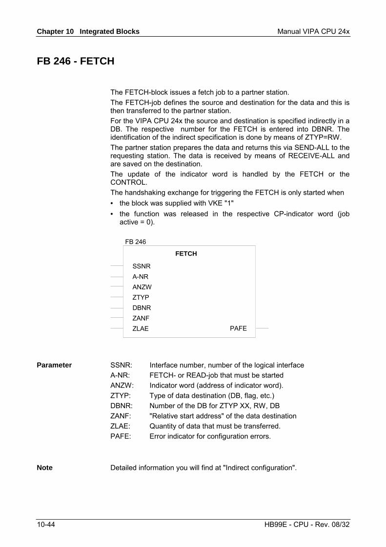
Chapter 10 Integrated Blocks Manual VIPA CPU 24x
10-44 HB99E - CPU - Rev. 08/32
FB 246 - FETCH
The FETCH-block issues a fetch job to a partner station. The FETCH-job defines the source and destination for the data and this is then transferred to the partner station. For the VIPA CPU 24x the source and destination is specified indirectly in a DB. The respective number for the FETCH is entered into DBNR. The identification of the indirect specification is done by means of ZTYP=RW. The partner station prepares the data and returns this via SEND-ALL to the requesting station. The data is received by means of RECEIVE-ALL and are saved on the destination. The update of the indicator word is handled by the FETCH or the CONTROL. The handshaking exchange for triggering the FETCH is only started when • the block was supplied with VKE "1" • the function was released in the respective CP-indicator word (job
active = 0).
SSNRA-NRANZWZTYPDBNRZANFZLAE PAFE
FB 246
FETCH
SSNR: Interface number, number of the logical interface A-NR: FETCH- or READ-job that must be started ANZW: Indicator word (address of indicator word). ZTYP: Type of data destination (DB, flag, etc.) DBNR: Number of the DB for ZTYP XX, RW, DB ZANF: "Relative start address" of the data destination ZLAE: Quantity of data that must be transferred. PAFE: Error indicator for configuration errors.
Detailed information you will find at "Indirect configuration".
Parameter
Note
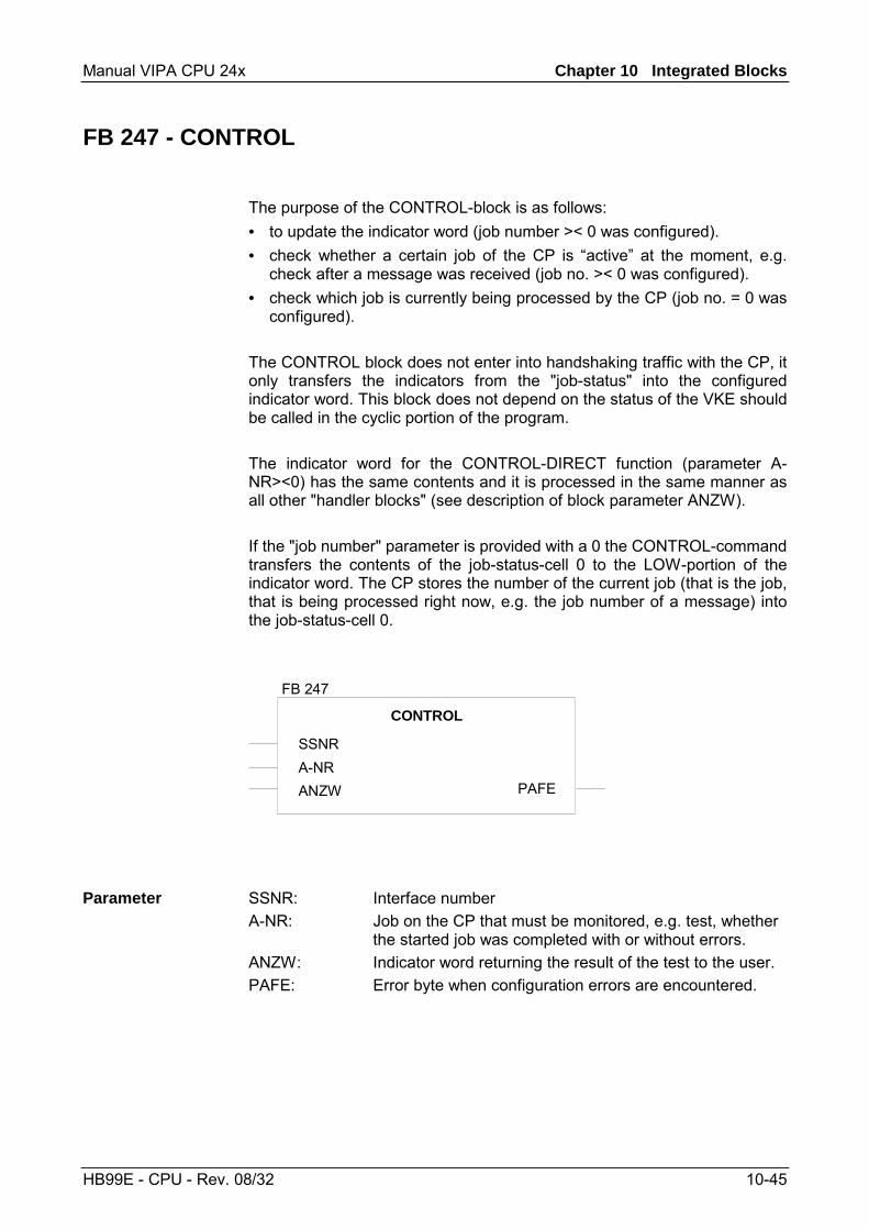
Manual VIPA CPU 24x Chapter 10 Integrated Blocks
HB99E - CPU - Rev. 08/32 10-45
FB 247 - CONTROL
The purpose of the CONTROL-block is as follows: • to update the indicator word (job number >< 0 was configured). • check whether a certain job of the CP is “active” at the moment, e.g.
check after a message was received (job no. >< 0 was configured). • check which job is currently being processed by the CP (job no. = 0 was
configured). The CONTROL block does not enter into handshaking traffic with the CP, it only transfers the indicators from the "job-status" into the configured indicator word. This block does not depend on the status of the VKE should be called in the cyclic portion of the program. The indicator word for the CONTROL-DIRECT function (parameter A-NR><0) has the same contents and it is processed in the same manner as all other "handler blocks" (see description of block parameter ANZW). If the "job number" parameter is provided with a 0 the CONTROL-command transfers the contents of the job-status-cell 0 to the LOW-portion of the indicator word. The CP stores the number of the current job (that is the job, that is being processed right now, e.g. the job number of a message) into the job-status-cell 0.
SSNRA-NRANZW PAFE
FB 247
CONTROL
SSNR: Interface number A-NR: Job on the CP that must be monitored, e.g. test, whether the started job was completed with or without errors. ANZW: Indicator word returning the result of the test to the user. PAFE: Error byte when configuration errors are encountered.
Parameter
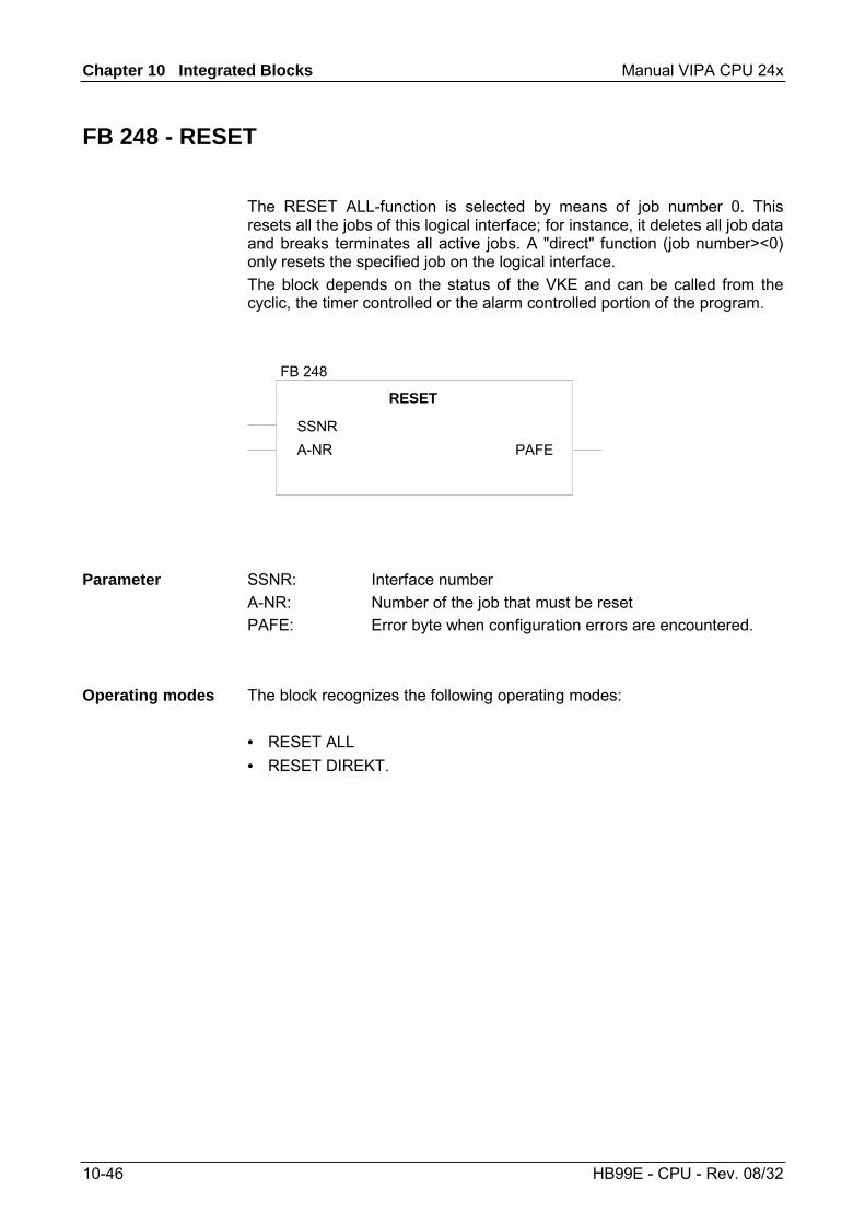
Chapter 10 Integrated Blocks Manual VIPA CPU 24x
10-46 HB99E - CPU - Rev. 08/32
FB 248 - RESET
The RESET ALL-function is selected by means of job number 0. This resets all the jobs of this logical interface; for instance, it deletes all job data and breaks terminates all active jobs. A "direct" function (job number><0) only resets the specified job on the logical interface. The block depends on the status of the VKE and can be called from the cyclic, the timer controlled or the alarm controlled portion of the program.
SSNRA-NR PAFE
FB 248
RESET
SSNR: Interface number A-NR: Number of the job that must be reset PAFE: Error byte when configuration errors are encountered.
The block recognizes the following operating modes: • RESET ALL • RESET DIREKT.
Parameter
Operating modes
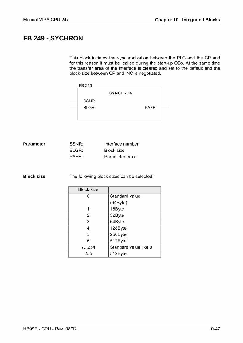
Manual VIPA CPU 24x Chapter 10 Integrated Blocks
HB99E - CPU - Rev. 08/32 10-47
FB 249 - SYCHRON
This block initiates the synchronization between the PLC and the CP and for this reason it must be called during the start-up OBs. At the same time the transfer area of the interface is cleared and set to the default and the block-size between CP and INC is negotiated.
SSNRBLGR PAFE
FB 249
SYNCHRON
SSNR: Interface number BLGR: Block size PAFE: Parameter error
The following block sizes can be selected:
Block size 0 Standard value
(64Byte) 1 16Byte 2 32Byte 3 64Byte 4 128Byte 5 256Byte 6 512Byte
7...254 Standard value like 0 255 512Byte
Parameter
Block size
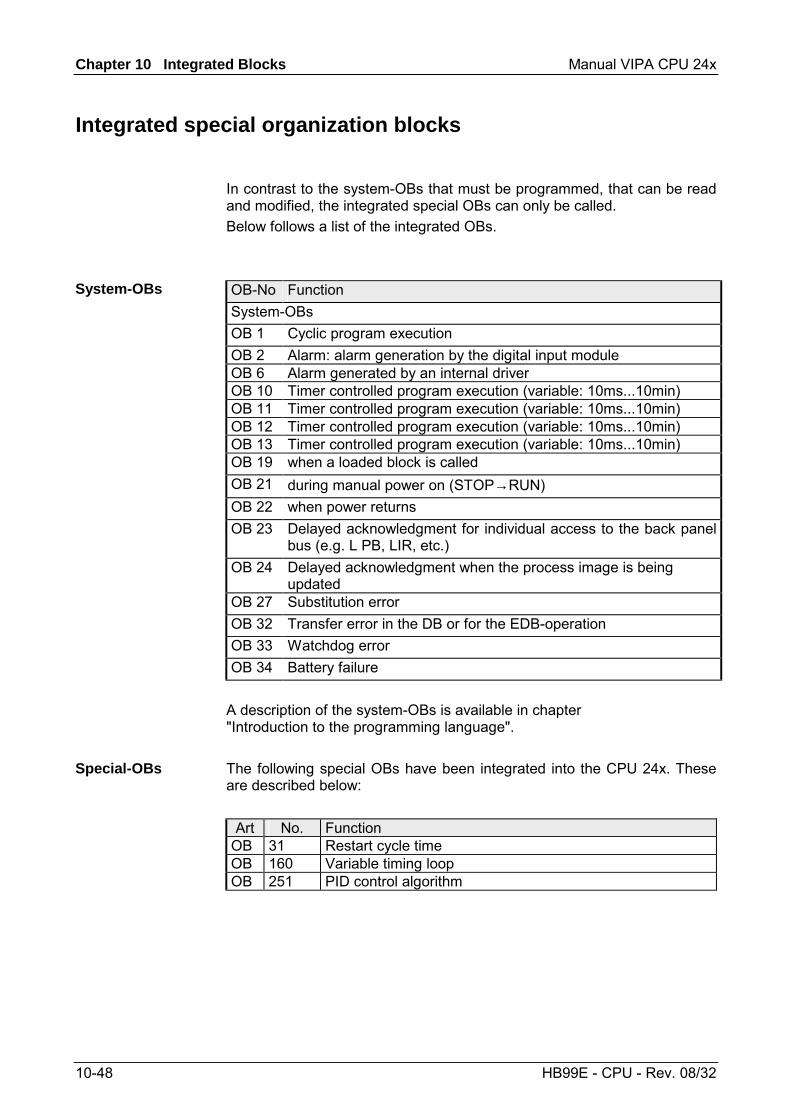
Chapter 10 Integrated Blocks Manual VIPA CPU 24x
10-48 HB99E - CPU - Rev. 08/32
Integrated special organization blocks
In contrast to the system-OBs that must be programmed, that can be read and modified, the integrated special OBs can only be called. Below follows a list of the integrated OBs. OB-No Function System-OBs OB 1 Cyclic program execution OB 2 Alarm: alarm generation by the digital input module OB 6 Alarm generated by an internal driver OB 10 Timer controlled program execution (variable: 10ms...10min) OB 11 Timer controlled program execution (variable: 10ms...10min) OB 12 Timer controlled program execution (variable: 10ms...10min) OB 13 Timer controlled program execution (variable: 10ms...10min) OB 19 when a loaded block is called OB 21 during manual power on (STOP→RUN) OB 22 when power returns OB 23 Delayed acknowledgment for individual access to the back panel
bus (e.g. L PB, LIR, etc.) OB 24 Delayed acknowledgment when the process image is being
updated OB 27 Substitution error OB 32 Transfer error in the DB or for the EDB-operation OB 33 Watchdog error OB 34 Battery failure
A description of the system-OBs is available in chapter "Introduction to the programming language". The following special OBs have been integrated into the CPU 24x. These are described below:
Art No. Function OB 31 Restart cycle time OB 160 Variable timing loop OB 251 PID control algorithm
System-OBs
Special-OBs

Manual VIPA CPU 24x Chapter 10 Integrated Blocks
HB99E - CPU - Rev. 08/32 10-49
OB 31 - Cycle time triggering
The timing of a program execution is monitored by a "cycle-time guard". If the execution time is longer than the pre-set cycle-time limit, e.g. 500ms, then the CPU goes to STOP mode. This can occur if: • the control program is of excessive length • your program is in an endless loop. A call to OB 31 (SPA OB31) can be used to re-trigger the cycle-time guard at any point within the program; i.e., the monitoring time for the cycle is started again. The monitoring time for the cycle can be defined: • in system data word 96 (EAC0h) or • in DB1.

Chapter 10 Integrated Blocks Manual VIPA CPU 24x
10-50 HB99E - CPU - Rev. 08/32
OB 160 - Variable timing loop
OB 160 "simulates" operation run-times. This provides timing facilities that are independent of the run-times of the different CPU and you can therefore program delay times for any CPU.
Before you issue the call to OB 160 the delay time in ms (range: 10 ...65535 or A0h ...FFFFh) must be loaded into the AKKU.
A delay time of one millisecond is required from your program. L KF +1000 SPA OB 160
Note! Please note the following when programming the OB 160: A process alarm (OB 2) and the timer alarm (OB 6) can interrupt the delay time (provided that alarms were not inhibited (AS)). The delay timer does not continue running during the interrupt! The delay time is also extended by active PG/OP-operations. It is for this reason that the defined times must be regarded as minimum times! OB 10...13 can not interrupt OB 160!
Procedure:
Example:
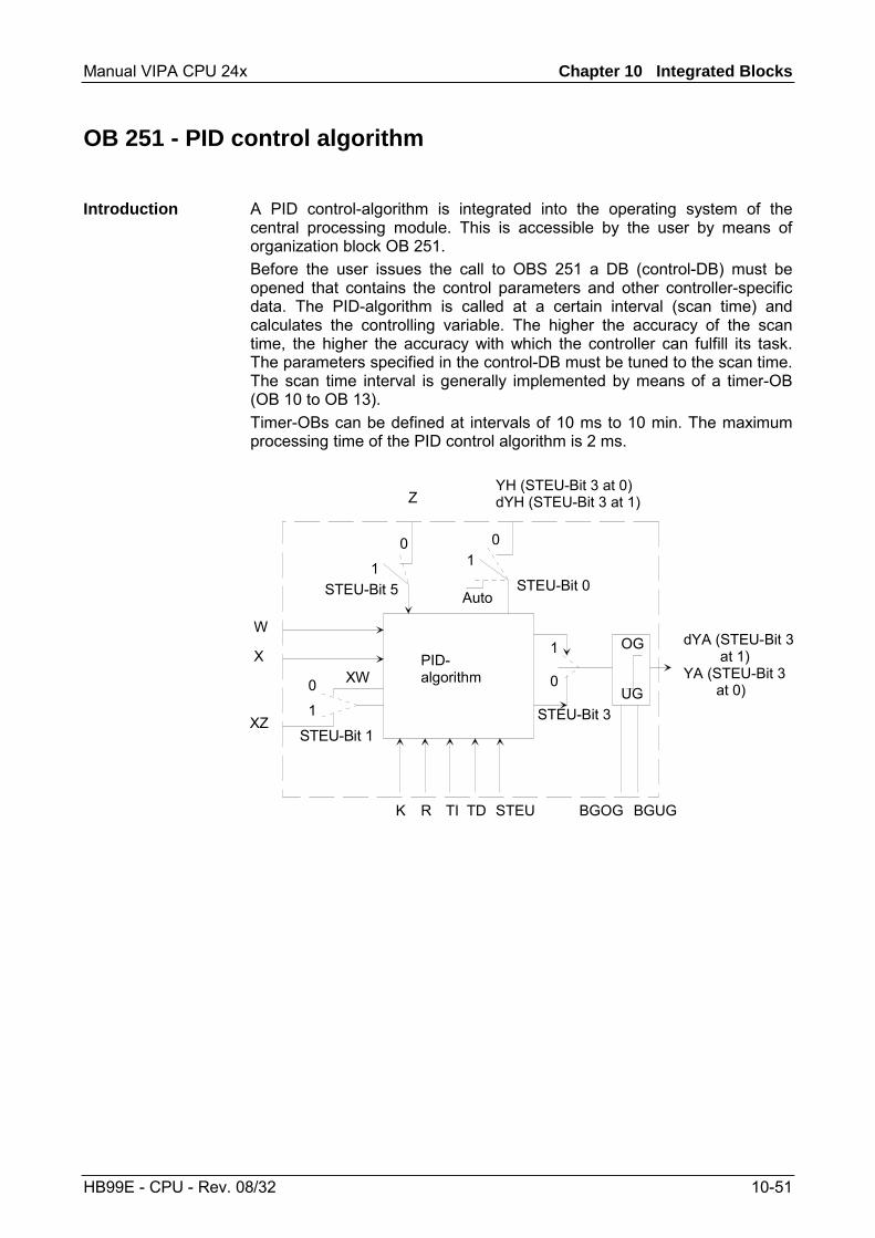
Manual VIPA CPU 24x Chapter 10 Integrated Blocks
HB99E - CPU - Rev. 08/32 10-51
OB 251 - PID control algorithm
A PID control-algorithm is integrated into the operating system of the central processing module. This is accessible by the user by means of organization block OB 251. Before the user issues the call to OBS 251 a DB (control-DB) must be opened that contains the control parameters and other controller-specific data. The PID-algorithm is called at a certain interval (scan time) and calculates the controlling variable. The higher the accuracy of the scan time, the higher the accuracy with which the controller can fulfill its task. The parameters specified in the control-DB must be tuned to the scan time. The scan time interval is generally implemented by means of a timer-OB (OB 10 to OB 13). Timer-OBs can be defined at intervals of 10 ms to 10 min. The maximum processing time of the PID control algorithm is 2 ms.
PID-algorithm0
1
XW
STEU-Bit 1
Auto
1
0
STEU-Bit 3
OG
UG
01
0
1STEU-Bit 0STEU-Bit 5
W
X
XZ
K R TI TD STEU BGOG BGUG
dYA (STEU-Bit 3 at 1)YA (STEU-Bit 3 at 0)
ZYH (STEU-Bit 3 at 0)dYH (STEU-Bit 3 at 1)
Introduction
Chapter 10 Integrated Blocks Manual VIPA CPU 24x
10-52 HB99E - CPU - Rev. 08/32
K = Proportional coefficient
K>0 positive control direction K<= negative control direction
Y dY YH dYH
====
controlling variable position increment control val. for man. inp.Position increment for man. input
R = R-parameter (p.p. 1000) TA = Scan time BGOG = Upper limit value TN = Reset time BGUG = Lower limit value TV = Rate time X = Actual value TI = TA/TN Z = Disturbance TD = TV/TA XZ = Alternate value for STEU = Control word control difference W = Set point YA = Controller output: XW = Control difference limited contr. variable dYA = Controller output: limited control increment
The quasi-continuous controller is designed for controlled systems that can be encountered in process-engineering as pressure, temperature or flow controllers, etc. Quantity "R" determines the proportional component of the PID-controller. If the regulator operate as a P-controller then R = 1 as with most other controller design procedures. The different P -, I - and D-components can be disabled by means of the respective parameters (R,TI and TD) by setting the relevant data words to zero. In this manner the required control structures (e.g. PI, PD - or PID-controller) can be implemented easily and simply. The differentiation can be connected to the differential control value XW or - via the XZ-input - a disturbance value or the inverted actual value X. To achieve an inverted controlling characteristic a negative value must be pre-set for K. If the control information (dY or Y) is at the level of a limiting value the I-component is turned off automatically in order to avoid a deterioration of the regulation behavior. During the configuration of the PID controller the switch settings in the block diagram are implemented by setting the respective bits in the control word "STEU".
Legend
Description

Manual VIPA CPU 24x Chapter 10 Integrated Blocks
HB99E - CPU - Rev. 08/32 10-53
Contr.bit
Name Signal status
Description
0 AUTO 0 1
Manual operation The following quantities are controlled under manual operation: X,k XWk-1 and PW k-1 XZ,k, XZ k-1 and PZ k-1, when STEU-Bit =1 Z k, and Z k-1, when STEU-Bit 5 =0 The quantity dD k-1, is set = 0. The algorithm is not calculated. Automatic operation
1 XZ EIN 0 1
The differentiation is connected to XW,k. The XZ-input is not used. The differentiation is provided with a different quantity via the XZ-input which must not be XW,k.
2 REG AUS 0 1
normal control operation When the controller is called (OB 251) all the quantities (DW 18 to DW 48) with the exception of K, R, TI, TD, BGOG, BGUG, YH,k and W,k are cleared in the controller-DB. The controller is turned off.
3 GESCHW 0 1
Positioning algorithm velocity algorithm
4 HANDART 0 If GESCHW = 0: After switching to manual operation the entered value YA is controlled exponentially in 4 scanning step to the selected manual value. Subsequently additional values are immediately transferred to the output of the controller. If GESCHW = 1: The manual values are transferred immediately to the output of the controller. The limiting values apply in manual mode.
1 If GESCHW =0: The last controlling variable that was sent to the output is retained. If GESCHW = 1: The control increment dY,k is set to zero.
5 NOZ 0 with disturbance quantity connected 1 without disturbance quantity connected
6 to 15 - these bits are used by the PID-algorithm as auxiliary flags.
The control program can be provided with constants or parameters. Parameters are entered via the respective data words. The controller operates in accordance with a PID algorithm. Its output signal can either be used as controlling variable (position-algorithm) or as a modified controlling variable (velocity-algorithm).
Control word STEU

Chapter 10 Integrated Blocks Manual VIPA CPU 24x
10-54 HB99E - CPU - Rev. 08/32
At a specific point in time t = k • TA the respective controlling increment dYk is calculated in accordance with the following formula:
• without disturbance variable connected (D11.5 = 1) and XW-assigned to differentiation (D11.1 =0)
dYk =K[(XWk-XWk-1)R+TI•XWk+1/2(TD(XWk - 2XWk-1 + XWk-2) + dDk-1)] =K (dPWk + dIk + dDk) • with disturbance variable connected (D11.5 = 0) and XW-assigned to
differentiator (D11.1 =0) dYk =K[(XWk-XWk-1)R+TI•XWk+1/2(TD(XWk - 2XWk-1 + XWk-2) + dDk-1)] + (Zk-Zk-1) =K (dPWk + dIk + dDk) + dZk • without disturbance variable connected (D11.5 = 1) and XZ-assigned to
differentiator (D11.1 =1) dYk =K[(XWk-XWk-1)R+TI•XWk+1/2(TD(XZk - 2XZk-1 + XZk-2) + dDk-1)] =K (dPWk + dIk + dDk) • with disturbance variable connected (D11.5 = 0) and XZ-assigned to
differentiator (D11.1 =1) dYk =K[(XWk-XWk-1)R+TI•XWk+1/2(TD(XZk - 2XZk-1 + XZk-2) + dDk-1)] + (Zk-Zk-1) =K (dPWk + dIk + dDk) + dZk P-comp. I- comp. D- comp. Z- comp. k: k-th scan For XWk-assignment: XWk = Wk - Xk PWk = XWk - XWk-1 QWk = PWk - PWk-1 = XWk-2XWk-1 + XWk-2 For XZ-assignment: PZk = XZk - XZk-1 QZk = PZk - PZk-1 = XZk - 2XZk-1 + XZk-2 This returns: dPWk = (XWk - XWk-1)R dIk = TI•XWk dDk = ½(TD•QWk + dDk-1) for XW-assignment = ½(TD•QZk + dDk-1) for XZ-assignment
Velocity algorithm

Manual VIPA CPU 24x Chapter 10 Integrated Blocks
HB99E - CPU - Rev. 08/32 10-55
The position-algorithm employs the same algorithm as the velocity-algorithm. It differs from the velocity-algorithm in that at the scan time tk the sum of all the control increments that were calculated up to this point (in DW 48) is placed on the output instead of the control-increment dYk. At the time tk the control variable Yk is calculated as follows: m=k Yk = ∑ dYm m=0
The interface of OB 251 to the outside world is the controller-DB. All to the information required for the calculation of the next control-variable are stored in the control-DB. Every controller requires a separate control-DB. The controller-related data is configured in this control-DB. The DB must consist of a minimum of 49 data words. If the opened DB is too short or if you have not opened a DB the CPU goes to STOP mode with a transfer error (MET).
Note! Before you issue the call to the control algorithm OB 251 you must open the associated control-DB!
Position algorithm
Configuration of the PID algorithm
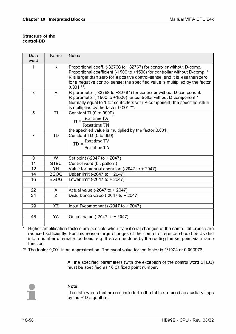
Chapter 10 Integrated Blocks Manual VIPA CPU 24x
10-56 HB99E - CPU - Rev. 08/32
Data word
Name Notes
1 K Proportional coeff. (-32768 to +32767) for controller without D-comp. Proportional coefficient (-1500 to +1500) for controller without D-comp. * K is larger than zero for a positive control-sense, and it is less than zero for a negative control sense; the specified value is multiplied by the factor 0,001 **.
3 R R-parameter (-32768 to +32767) for controller without D-component. R-parameter (-1500 to +1500) for controller without D-component * Normally equal to 1 for controllers with P-component; the specified value is multiplied by the factor 0,001 **.
5 TI Constant TI (0 to 9999)
TNResettimeTA ScantimeTI =
the specified value is multiplied by the factor 0,001. 7 TD Constant TD (0 to 999)
TAScantimeTV RatetimeTD =
9 W Set point (-2047 to + 2047)
11 STEU Control word (bit pattern) 12 YH Value for manual operation (-2047 to + 2047) 14 BGOG Upper limit (-2047 to + 2047) 16 BGUG Lower limit (-2047 to + 2047)
22 X Actual value (-2047 to + 2047) 24 Z Disturbance value (-2047 to + 2047)
29 XZ Input D-component (-2047 to + 2047)
48 YA Output value (-2047 to + 2047)
* Higher amplification factors are possible when transitional changes of the control difference are reduced sufficiently. For this reason large changes of the control difference should be divided into a number of smaller portions; e.g. this can be done by the routing the set point via a ramp function.
** The factor 0,001 is an approximation. The exact value for the factor is 1/1024 or 0,000976. All the specified parameters (with the exception of the control word STEU) must be specified as 16 bit fixed point number.
Note! The data words that are not included in the table are used as auxiliary flags by the PID algorithm.
Structure of the control-DB
Manual VIPA CPU 24x Chapter 10 Integrated Blocks
HB99E - CPU - Rev. 08/32 10-57
PID-controller in the PLC program You can initialize a number of different PID controllers by multiple calls to OB 251. The respective control DB must be opened before the call is issued to OB 251.
Note! In the high-byte of control-word DW 11 (DL11) contains important control information. For this reason it is important to ensure that write access is only performed by means of T DR11 or SU D 11.0 to 11.7 or RU D 11.0 to 11.7.
The selected scan time must not be too high to be able to use the well-known analog approach for digital control circuits. Experience has shown that a scan time for TA of app. 1/10 of the time constant of TRKdom (=dominant time constant for the closed control loop) results in a control response that is similar to the analog equivalent. The time constant TRKdom determines the step response of the closed control loop. TA = 1/10 • TRKdom OB 251 must always be called from the timer-OB (OB 13) to guarantee a constant scan time.
Initialization and call
Choice of scan time
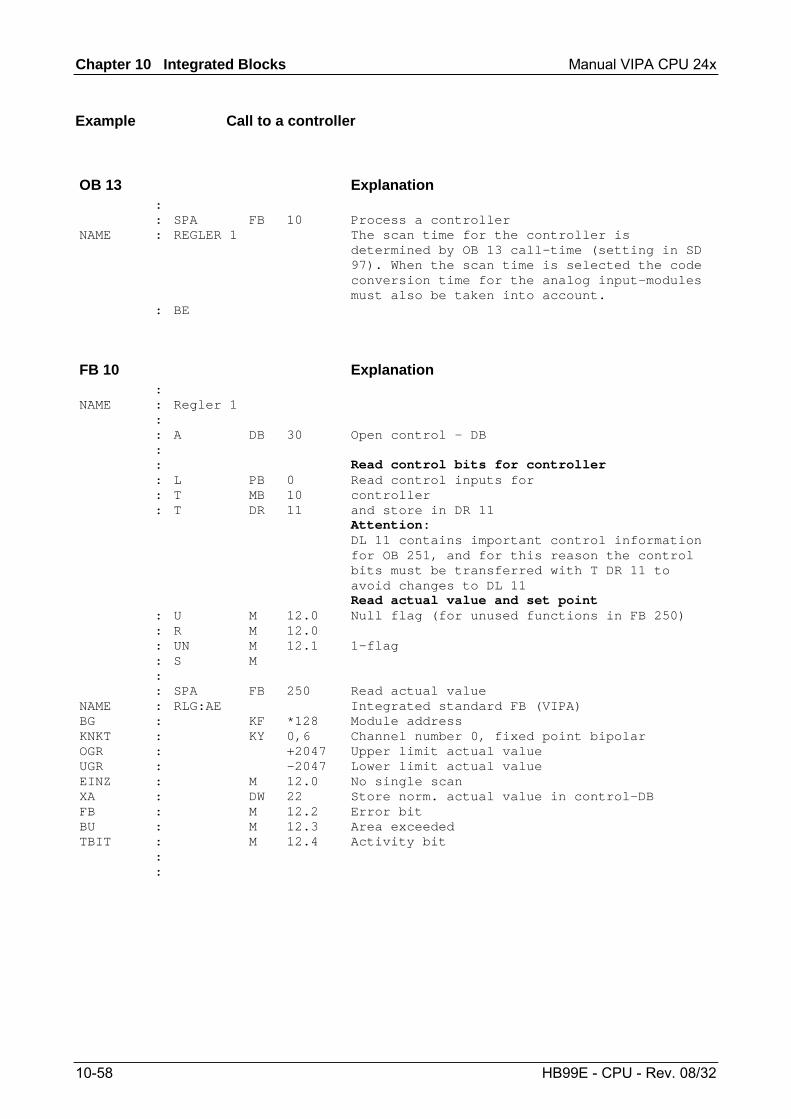
Chapter 10 Integrated Blocks Manual VIPA CPU 24x
10-58 HB99E - CPU - Rev. 08/32
Call to a controller
OB 13 Explanation : : SPA FB 10 Process a controller NAME : REGLER 1 The scan time for the controller is
determined by OB 13 call-time (setting in SD 97). When the scan time is selected the code conversion time for the analog input-modules must also be taken into account.
: BE
FB 10 Explanation : NAME : Regler 1 : : A DB 30 Open control - DB : : Read control bits for controller : L PB 0 Read control inputs for : T MB 10 controller : T DR 11 and store in DR 11
Attention: DL 11 contains important control information for OB 251, and for this reason the control bits must be transferred with T DR 11 to avoid changes to DL 11
Read actual value and set point : U M 12.0 Null flag (for unused functions in FB 250) : R M 12.0 : UN M 12.1 1-flag : S M : : SPA FB 250 Read actual value NAME : RLG:AE Integrated standard FB (VIPA) BG : KF *128 Module address KNKT : KY 0,6 Channel number 0, fixed point bipolar OGR : +2047 Upper limit actual value UGR : -2047 Lower limit actual value EINZ : M 12.0 No single scan XA : DW 22 Store norm. actual value in control-DB FB : M 12.2 Error bit BU : M 12.3 Area exceeded TBIT : M 12.4 Activity bit : :
Example
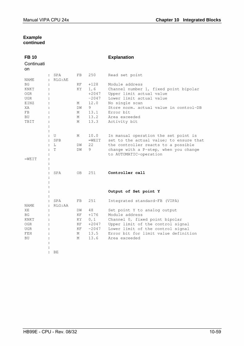
Manual VIPA CPU 24x Chapter 10 Integrated Blocks
HB99E - CPU - Rev. 08/32 10-59
FB 10 Continuation
Explanation
: SPA FB 250 Read set point NAME : RLG:AE BG : KF +128 Module address KNKT : KY 1,6 Channel number 1, fixed point bipolar OGR : +2047 Upper limit actual value UGR : -2047 Lower limit actual value EINZ : M 12.0 No single scan XA : DW 9 Store norm. actual value in control-DB FB : M 13.1 Error bit BU : M 13.2 Area exceeded TBIT : M 13.3 Activity bit : : : U M 10.0 In manual operation the set point is : SPB =WEIT set to the actual value; to ensure that : L DW 22 the controller reacts to a possible : T DW 9 change with a P-step, when you change : to AUTOMATIC-operation =WEIT : : : : SPA OB 251 Controller call : : : : Output of Set point Y : : SPA FB 251 Integrated standard-FB (VIPA) NAME : RLG:AA XE : DW 48 Set point Y to analog output BG : KF +176 Module address KNKT : KY 0,1 Channel 0, fixed point bipolar OGR : KF +2047 Upper limit of the control signal UGR : KF -2047 Lower limit of the control signal FEH : M 13.5 Error bit for limit value definition BU : M 13.6 Area exceeded : : : BE
Example continued
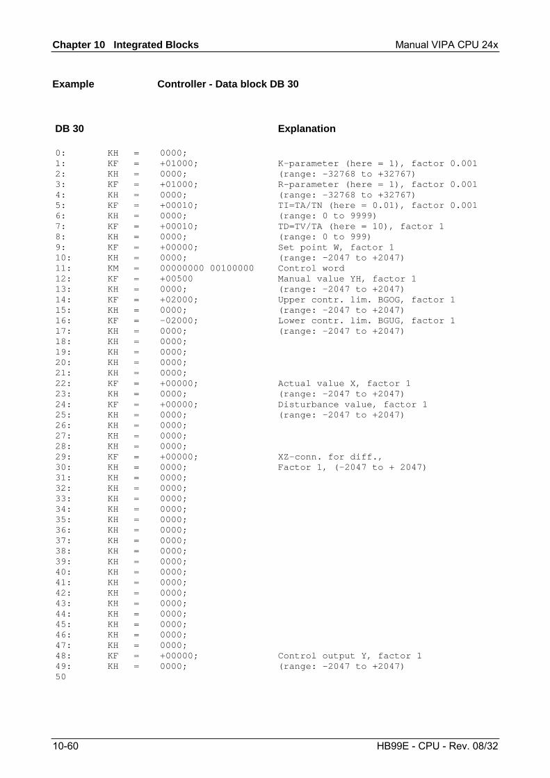
Chapter 10 Integrated Blocks Manual VIPA CPU 24x
10-60 HB99E - CPU - Rev. 08/32
Controller - Data block DB 30
DB 30 Explanation 0: KH = 0000; 1: KF = +01000; K-parameter (here = 1), factor 0.001 2: KH = 0000; (range: -32768 to +32767) 3: KF = +01000; R-parameter (here = 1), factor 0.001 4: KH = 0000; (range: -32768 to +32767) 5: KF = +00010; TI=TA/TN (here = 0.01), factor 0.001 6: KH = 0000; (range: 0 to 9999) 7: KF = +00010; TD=TV/TA (here = 10), factor 1 8: KH = 0000; (range: 0 to 999) 9: KF = +00000; Set point W, factor 1 10: KH = 0000; (range: -2047 to +2047) 11: KM = 00000000 00100000 Control word 12: KF = +00500 Manual value YH, factor 1 13: KH = 0000; (range: -2047 to +2047) 14: KF = +02000; Upper contr. lim. BGOG, factor 1 15: KH = 0000; (range: -2047 to +2047) 16: KF = -02000; Lower contr. lim. BGUG, factor 1 17: KH = 0000; (range: -2047 to +2047) 18: KH = 0000; 19: KH = 0000; 20: KH = 0000; 21: KH = 0000; 22: KF = +00000; Actual value X, factor 1 23: KH = 0000; (range: -2047 to +2047) 24: KF = +00000; Disturbance value, factor 1 25: KH = 0000; (range: -2047 to +2047) 26: KH = 0000; 27: KH = 0000; 28: KH = 0000; 29: KF = +00000; XZ-conn. for diff., 30: KH = 0000; Factor 1, (-2047 to + 2047) 31: KH = 0000; 32: KH = 0000; 33: KH = 0000; 34: KH = 0000; 35: KH = 0000; 36: KH = 0000; 37: KH = 0000; 38: KH = 0000; 39: KH = 0000; 40: KH = 0000; 41: KH = 0000; 42: KH = 0000; 43: KH = 0000; 44: KH = 0000; 45: KH = 0000; 46: KH = 0000; 47: KH = 0000; 48: KF = +00000; Control output Y, factor 1 49: KH = 0000; (range: -2047 to +2047) 50
Example
Manual VIPA CPU 24x Chapter 10 Integrated Blocks
HB99E - CPU - Rev. 08/32 10-61
Integrated block DB 1
The CPU 24x provides certain functions that you can adapt to your requirements (configuration): • manual address definition for directly installed modules, • configuration of directly installed modules, • assignment of data areas in the CPU 24x DP, • calling intervals for timer controlled program execution, • definition of system properties.
Note! The system-200V-specific settings can also be defined by means of the VIPA WinNCS. This generates a DB1 that you must export as s5d-file and that can be transferred into the CPU.
To simplify configuration a sample DB 1 with default values (default-parameters) is integrated in the CPU. If you load the default-DB1 from the PLC into the PG after an "overall reset" and display this on screen you will see the following: Baustein #DB 1 BIB #0 00000: KC = DB1¨TFB:¨OB13¨10¨;¨SDP:¨; 00012 KC = ¨WD¨500¨;¨END¨; Blanks or spaces are shown as ¨ in the above. This default DB contains a parameter block for every function. Every parameter block starts with a block identification followed by a colon. The parameter blocks contain the individual parameters for the respective functions. A parameter block always starts with a block identification followed by a colon. The colon is followed by at least one space. The semicolon (;) denotes the end of the parameter block.
Outline
Structure and settings for DB 1
Chapter 10 Integrated Blocks Manual VIPA CPU 24x
10-62 HB99E - CPU - Rev. 08/32
The following parameter blocks are available for the VIPA CPU 24x: Block
identifier Significance/default setting
′DB1′ Header label ′SL1: ′; Included for reasons of compatibility with SL1. This is
never executed. ′CLP: ′; Clock-parameters: parameter block for the integrated
clock/ no clock function is activated. ′UAT: ′; User Address Table
Manual address identifier for directly installed modules ′Pxx: ′; Configuration of directly installed modules. ′DPS: ′; DP Slave
Re-assign data area for Profibus-coupler in CPU 24x DP. ′SDP: ′; System-Dependent-parameter: parameter block for
system properties/ cycle time monitoring is preset to 500 ms.
′TFB: ′; Timer-Function-Blocks: parameter block for timer controlled program execution: OB 13 is called at 100 ms intervals.
′ERT: ′; Error Return: address for configuration error-code/no default settings.
′END ′; End identifier for DB 1. That of parameter blocks in the DB 1 is not fixed; individual blocks must be separated by a semicolon (;). The semicolon must be separated from the next block identifier by at least one space. Defining the address for the configuration error code in DB 1 Parameter block "ERT:" offers a simple option to correct configuration errors. For this reason you should add this block to DB 1 before you change or insert other parameters. Since the parameter block is only of importance during the implementation phase you should delete it for "normal" operations to save space. In order to locate and correct configuration errors easily can you instruct the PLC to output error messages in encoded form. You must only specify where the CPU should save the error code. This entry is required in parameter-block "ERT:" of the DB 1. The error code can be saved in: • Flag words, • Data words of a data block. The entire error code requires 20 flag bytes or 10 data words. You must only specify the start address for the error code I parameter block "ERT:", e.g.: ERT: ERR MBx or ERT: ERR DBxDWy
Parameter blocks
Configuration error code

Manual VIPA CPU 24x Chapter 10 Integrated Blocks
HB99E - CPU - Rev. 08/32 10-63
• Output of default-DB1 at the PG, • use the cursor to go to the required parameter block, • add/modify the parameter, • transfer the modified DB 1 into the AG, • change CPU from STOP→RUN. The modified DB1-parameters are retrieved.
Note! If the CPU recognizes a configuration error in DB 1 then the CPU remains in STOP mode after switching from STOP→RUN (red LED on). In addition the bit "SYSFE" and the combined error bit (BS7 bit 2) is set in the U-STACK.
DB 1 consists of: • the header label DB 1 • one or more parameter blocks e.g.: SDP: WD 500 a parameter block consists of: • a block identifier e.g.: SDP: • one or more parameters e.g.: WD 500 a parameter consists of: • a parameter name e.g.: WD • one or more arguments e.g.: 500 • a block end identifier: ; (semicolon) • an end code: END
DB1 KC=DB1"ERT:"ERR"MB200";;"TFB KC=:"OB13"10";;"SDP:"WD"500"; KC=;;"END";
Procedure when configuring DB 1
Rules for the configuration of DB 1
Example
Chapter 10 Integrated Blocks Manual VIPA CPU 24x
10-64 HB99E - CPU - Rev. 08/32
The following section specifies all the rules that you must satisfy if you wish to change parameters in the DB 1 or if you want to add entire parameter blocks. These rules must be followed since the CPU would otherwise not be able to "understand" your rules.
• DB 1 must start with the entry "DB1". These three characters must not be separated by fillers. The header must be followed by one or more filler characters.
• The header label and the filler is followed by the block-identifier of the parameter block. The sequence of the parameter blocks in the DB 1 is not important. The block identifier marks a block of common parameters. The block identifier must be followed by a colon (:). If the colon is omitted the CPU skips the block and issues an error message. The colon after the block identifier must be followed by at least one filler character.
• This is followed by a parameter name. Parameter names are names for individual parameters within a parameter block. In one block the first four characters of the parameter name must be unique. At least one filler character must follow after the parameter name.
• Every parameter name is associated with at least one argument. An argument is either a number or an operand that you must enter. If several arguments are supplied for a parameter name, then all the arguments must be separated by at least one filler character. The last argument must also be followed by at least one filler character.
• The end of the block must be specified by a semicolon (;). The semicolon must also be followed by at least one filler character. If you should omit the semicolon this would result in misinterpretations in the CPU.
• The semicolon can be followed by additional parameter blocks. • The end of the last parameter block must be followed by the end
identifier "END". This marks the end of DB 1. If you should forget to insert this end identifier this would result in errors in the CPU.
Standard filler characters are: space and comma.
Rules
Manual VIPA CPU 24x Chapter 10 Integrated Blocks
HB99E - CPU - Rev. 08/32 10-65
You can add commentaries to your DB 1. You can insert these commentaries at every point a filler character can be inserted. The commentary identifier (#) must start and end the commentary. The text between two commentary identifiers must not contain any additional # characters. The commentary must be followed by at least one filler character. To increase legibility of parameter names you can add any number of characters to the abbreviation if this is followed by an underscore. e.g.: WD becomes WD_Cycmonitor. At least one filler character must follow after the end of the compound parameter name. The following rule can be used as an aid for the control of your DB 1: At least 1 space must be located: after the header and in front of and after the block identifier, parameter name, argument and semicolon. If you should encounter errors during the configuration that prevents the PLC from going to RUN mode you can locate and recognize configuration errors as follows: • by means of the configuration error code, • by means of the analysis function "USTACK". Example You have declared the initial address DB 3 DW0 in parameter block "ERT:" and the configured DB 1 was already transferred into the PLC. You continue with the configuration of DB 1. After the changed DB1 was transferred into the PLC you note that the CPU remains in STOP mode. You then determine that the reason for the STOP is a configuration error in USTACK. In order to find the error you display DB 3 on the PG. The screen displays the entire contents of DB 3; data words DW 0 to DW 9 contain the configuration error code.
Commentary
Recognizing and removing configuration errors
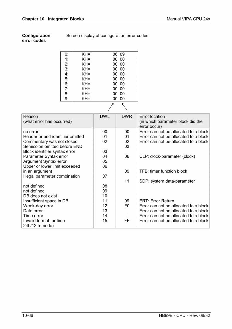
Chapter 10 Integrated Blocks Manual VIPA CPU 24x
10-66 HB99E - CPU - Rev. 08/32
Screen display of configuration error codes
0: KH= 06 09 1: KH= 00 00 2: KH= 00 00 3: KH= 00 00 4: KH= 00 00 5: KH= 00 00 6: KH= 00 00 7: KH= 00 00 8: KH= 00 00 9: KH= 00 00
Reason (what error has occurred)
DWL DWR Error location (in which parameter block did the error occur)
no error 00 00 Error can not be allocated to a blockHeader or end-identifier omitted 01 01 Error can not be allocated to a blockCommentary was not closed 02 02 Error can not be allocated to a blockSemicolon omitted before END 03 Block identifier syntax error 03 Parameter Syntax error 04 06 CLP: clock-parameter (clock) Argument Syntax error 05 Upper or lower limit exceeded 06 in an argument 09 TFB: timer function block Illegal parameter combination 07 11 SDP: system data-parameter not defined 08 not defined 09 DB does not exist 10 Insufficient space in DB 11 99 ERT: Error Return Week-day error 12 F0 Error can not be allocated to a blockDate error 13 . Error can not be allocated to a blockTime error 14 . Error can not be allocated to a blockInvalid format for time 24h/12 h-mode)
15 FF Error can not be allocated to a block
Configuration error codes

Manual VIPA CPU 24x Chapter 10 Integrated Blocks
HB99E - CPU - Rev. 08/32 10-67
If the CPU detects a configuration error in the DB 1 when it starts it remains in STOP mode and deposits the location where the error occurred in the USTACK. USTACK contains the absolute (error) address as well as the relative (error) address. The STEP-address counter (SAZ) in USTACK either pints to the address or directly in front of the address that contains the bad entry. Addresses are byte addresses. Furthermore bits SYSFE and the compound error bit (BS7 bit 2) are set in the U-STACK.
Different to other data-blocks, DB 1 is only processed once, i.e. when the PLC is rebooted. This was done to reserve the DB 1 for a special purpose. This special purpose is the configuration of the PLC by means of DB 1. Configuration means that you enter the parameters into data block DB1 that are intended for those internal functions that should be used by the PLC. These DB 1 entries are only transferred to the operating system of the PLC when this is rebooted. For this reason every modification of DB 1 must be followed by the corresponding reboot. You can initiate a reboot by switching from POWER-OFF→POWER-ON or STOP→RUN. The PLC then retrieves the parameters from DB 1 and stores them in the system data area.
Note! The CPU remains in STOP mode if it should detect a configuration error during start-up. In this case the red LED in the operating panel is turned on and the USTACK contains the error address of DB 1.
Locating a configuration error in "USTACK"
Transfer of DB 1 parameters into the PLC
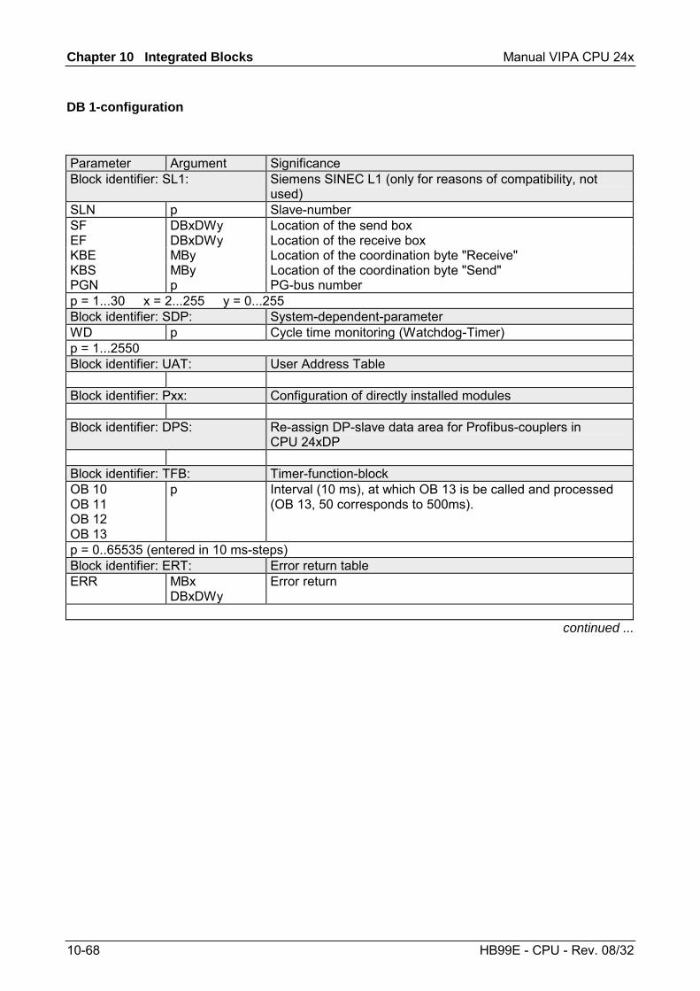
Chapter 10 Integrated Blocks Manual VIPA CPU 24x
10-68 HB99E - CPU - Rev. 08/32
Parameter Argument Significance Block identifier: SL1: Siemens SINEC L1 (only for reasons of compatibility, not
used) SLN p Slave-number SF DBxDWy Location of the send box EF DBxDWy Location of the receive box KBE MBy Location of the coordination byte "Receive" KBS MBy Location of the coordination byte "Send" PGN p PG-bus number p = 1...30 x = 2...255 y = 0...255 Block identifier: SDP: System-dependent-parameter WD p Cycle time monitoring (Watchdog-Timer) p = 1...2550 Block identifier: UAT: User Address Table Block identifier: Pxx: Configuration of directly installed modules Block identifier: DPS: Re-assign DP-slave data area for Profibus-couplers in
CPU 24xDP Block identifier: TFB: Timer-function-block OB 10 OB 11 OB 12 OB 13
p Interval (10 ms), at which OB 13 is be called and processed (OB 13, 50 corresponds to 500ms).
p = 0..65535 (entered in 10 ms-steps) Block identifier: ERT: Error return table ERR MBx
DBxDWy Error return
continued ...
DB 1-configuration

Manual VIPA CPU 24x Chapter 10 Integrated Blocks
HB99E - CPU - Rev. 08/32 10-69
... continue Parameter Argument Significance Block identifier: CLP: Clock-parameter (clock) CF p Enter correction factor (Correction Factor) CLK DBxDWy,
MWz,EWv Location of the clock data (Clock Data)
or AWv STW DBxDWy,
MWz,EWv Location of the status word (Status Word)
or AWv STP J/Y/N Update clock in STOP-mode (STOP) SAV J/Y/N Save time after most recent STOP→RUN transition or
POWER-OFF (SAVe) OHE J/Y/N Enable operating time counter
(Operation Hour counter Enable) SET wt tt.mm.jj Set date/time hh:mn:ss1
AM/PM2
TIS wt tt.mm. Set timer interrupt (Timer Interrupt Set) hh:mn:ss1 AM/PM2 OHS hhhhhh:mn.ss1 Set operating time counter
(Operation Hour counter Set) wt = 1...7 (day of week =So...Sa) tt = 01...31 (day) mm = 01...12 (month) jj = 0...99 (year) hh = 00...23 (hours) mn = 00...59 (minutes) ss = 00...59 (seconds) hhhhhh = 0...999999 (hours)
p = -400...400 v = 0...126 x = 2...255 y = 0...255 z = 0...254 j/J = yes y/Y = yes n/N = no
1) If you wish to prevent that an argument is transferred (e.g. seconds) you should enter XX! The clock continues with its current data. This argument is not used in parameter block TIS.
2) If you enter AM or PM after the time the clock runs in the 12 hour mode. If you omit this argument the clock runs in the 24-hour mode. You must use the same time mode in parameter blocks SET and TIS.
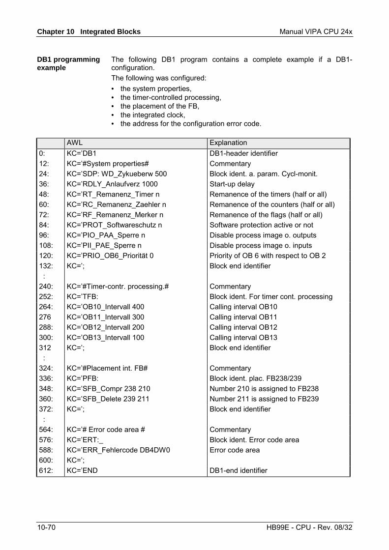
Chapter 10 Integrated Blocks Manual VIPA CPU 24x
10-70 HB99E - CPU - Rev. 08/32
The following DB1 program contains a complete example if a DB1-configuration. The following was configured: • the system properties, • the timer-controlled processing, • the placement of the FB, • the integrated clock, • the address for the configuration error code.
AWL Explanation 0: KC=’DB1 DB1-header identifier 12: KC=’#System properties# Commentary 24: KC=’SDP: WD_Zykueberw 500 Block ident. a. param. Cycl-monit. 36: KC=’RDLY_Anlaufverz 1000 Start-up delay 48: KC=’RT_Remanenz_Timer n Remanence of the timers (half or all) 60: KC=’RC_Remanenz_Zaehler n Remanence of the counters (half or all) 72: KC=’RF_Remanenz_Merker n Remanence of the flags (half or all) 84: KC=’PROT_Softwareschutz n Software protection active or not 96: KC=’PIO_PAA_Sperre n Disable process image o. outputs 108: KC=’PII_PAE_Sperre n Disable process image o. inputs 120: KC=’PRIO_OB6_Priorität 0 Priority of OB 6 with respect to OB 2 132: KC=’; Block end identifier : 240: KC=’#Timer-contr. processing.# Commentary 252: KC=’TFB: Block ident. For timer cont. processing 264: KC=’OB10_Intervall 400 Calling interval OB10 276 KC=’OB11_Intervall 300 Calling interval OB11 288: KC=’OB12_Intervall 200 Calling interval OB12 300: KC=’OB13_Intervall 100 Calling interval OB13 312 KC=’; Block end identifier : 324: KC=’#Placement int. FB# Commentary 336: KC=’PFB: Block ident. plac. FB238/239 348: KC=’SFB_Compr 238 210 Number 210 is assigned to FB238 360: KC=’SFB_Delete 239 211 Number 211 is assigned to FB239 372: KC=’; Block end identifier : 564: KC=’# Error code area # Commentary 576: KC=’ERT:_ Block ident. Error code area 588: KC=’ERR_Fehlercode DB4DW0 Error code area 600: KC=’; 612: KC=’END DB1-end identifier
DB1 programming example
Manual VIPA CPU 24x Chapter 11 Clock functions
HB99E - CPU - Rev. 08/32 11-1
Chapter 11 Clock functions
This chapter describes the structure and the configuration of the integrated clock. The integrated clock is a built in to the CPU-types: CPU 243 and CPU 244.
Topic Page Chapter 11 Clock functions ............................................................. 11-1
General .............................................................................................. 11-2 Configuration of the integrated clock .................................................. 11-3 Structure of the clock data area.......................................................... 11-7 Structure of the status word.............................................................. 11-10 Setting and reading the clock ........................................................... 11-12 Alarm functions ................................................................................ 11-19 Operating time counter ..................................................................... 11-22
Outline
Contents
Chapter 11 Clock functions Manual VIPA CPU 24x
11-2 HB99E - CPU - Rev. 08/32
General
The CPU-types CPU 243 and CPU 244 contain an integrated real-time clock. The clock provides additional facilities to monitor a process: • Timing and alarm functions
e.g. to supervise the duration of a process. • Operating time counter
e.g. to determine maintenance schedules. • Clock function
e.g. to determine the time when an error caused the CPU to STOP. The accuracy of the clock is ± 22 seconds (maximum) per day at 25°C.
If a battery has been installed the clock also runs when power is removed (POWER-OFF). If the battery has not been installed a POWER-ON initializes the clock settings to 01.01.89 12.00.00 and the day of the week to 1. This also sets the clock to 24-hour mode. Therefore the battery should only be changed when POWER is ON since you would otherwise lose the clock settings.
Battery backup for the hardware clock
Manual VIPA CPU 24x Chapter 11 Clock functions
HB99E - CPU - Rev. 08/32 11-3
Configuration of the integrated clock
A clock data area and a status word are required if you wish to use the clock. For this purpose you must save the following information in system data 8 to 10: • the position of the clock data area, • the position of the status word.
You can configure the clock by means of DB 1 (parameter block CLP). Another possibility to configure the integrated clock is explained below. You can configure the clock in an FB programmed by yourself. This would be called from one of the two start-up OBs, OBS 21 and OBS 22. The parameters are stored in the system data located in the function block by means of the transfer operations (e.g. "TBS, TNB"). The location of the clock data area and the status word is determined by system data words 8 to 10. This defines whether the area is a flag area or a data block. The exact position of the defined area is also determined here. The operating system does not provide a standard setting for these system data cells so that the clock is inaccessible in this case. The following table provides information on the significance of the different bytes of system data words 8 to 10. System data words 11 and 12 is explained after the table.
Requirements
Configuration
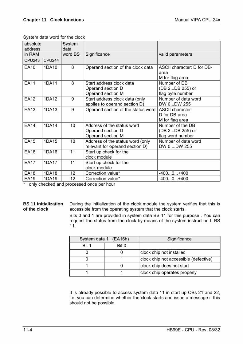
Chapter 11 Clock functions Manual VIPA CPU 24x
11-4 HB99E - CPU - Rev. 08/32
System data word for the clock absolute address in RAM
System data word BS
Significance
valid parameters
CPU243 CPU244 EA10 1DA10 8 Operand section of the clock data ASCII character: D for DB-
area M for flag area
EA11 1DA11 8 Start address clock data Operand section D Operand section M
Number of DB (DB 2...DB 255) or flag byte number
EA12 1DA12 9 Start address clock data (only applies to operand section D)
Number of data word DW 0...DW 255
EA13 1DA13 9 Operand section of the status word ASCII character: D for DB-area M for flag area
EA14 1DA14 10 Address of the status word Operand section D Operand section M
Number of the DB (DB 2...DB 255) or flag word number
EA15 1DA15 10 Address of the status word (only relevant for operand section D)
Number of data word DW 0 ...DW 255
EA16 1DA16 11 Start up check for the clock module
EA17 1DA17 11 Start up check for the clock module
EA18 1DA18 12 Correction value* -400...0...+400 EA19 1DA19 12 Correction value* -400...0...+400 * only checked and processed once per hour
During the initialization of the clock module the system verifies that this is accessible from the operating system that the clock starts. Bits 0 and 1 are provided in system data BS 11 for this purpose . You can request the status from the clock by means of the system instruction L BS 11.
System data 11 (EA16h) Significance Bit 1 Bit 0
0 0 clock chip not installed 0 1 clock chip not accessible (defective) 1 0 clock chip does not start 1 1 clock chip operates properly
It is already possible to access system data 11 in start-up OBs 21 and 22, i.e. you can determine whether the clock starts and issue a message if this should not be possible.
BS 11 initialization of the clock
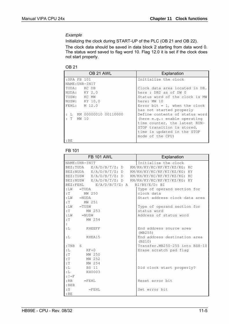
Manual VIPA CPU 24x Chapter 11 Clock functions
HB99E - CPU - Rev. 08/32 11-5
Example Initializing the clock during START-UP of the PLC (OB 21 and OB 22). The clock data should be saved in data block 2 starting from data word 0. The status word saved to flag word 10. Flag 12.0 it is set if the clock does not start properly.
OB 21 OB 21 AWL Explanation
:SPA FB 101 Initialize the clock NAME:UHR-INIT TUDA: KC DB Clock data area located in DB.NUDA: KY 2,0 here : DB2 as of DW 0 TUSW: KC MW Status word of the clock is MWNUSW: KY 10,0 here: MW 10 FEHL: M 12.0 Error bit = 1, when the clock
has not started properly : L KM 00000010 00110000 Define contents of status word: T MW 10 (here e.g.: enable operating
time counter, the latest RUN-STOP transition is stored, time is updated in the STOP mode of the CPU)
:BE
FB 101 FB 101 AWL Explanation
NAME:UHR-INIT Initialize the clock BEZ:TUDA E/A/D/B/T/Z: D KM/KH/KY/KC/KF/KT/KZ/KG: KC BEZ:NUDA E/A/D/B/T/Z: D KM/KH/KY/KC/KF/KT/KZ/KG: KY BEZ:TUSW E/A/D/B/T/Z: D KM/KH/KY/KC/KF/KT/KZ/KG: KC BEZ:NUSW E/A/D/B/T/Z: D KM/KH/KY/KC/KF/KT/KZ/KG: KY BEZ:FEHL E/A/D/B/T/Z: A BI/BY/E/D: BI :LW =TUDA Type of operand section for :T MW 250 clock data :LW =NUDA Start address clock data area :T MW 251 :LW =TUSW Type of operand section for :T MW 253 status word :LW =NUSW Address of status word :T MW 254 : :L KHEEFF End address source area
(MB255) :L KHEA15 End address destination area
(BS10) :TNB 6 Transfer.MB250-255 into BS8-10:L KF+0 Erase scratch pad flag :T MW 250 :T MW 252 :T MW 254 :L BS 11 Did clock start properly? :L KH0003 :!=F :RB =FEHL Reset error bit :BEB :S =FEHL Set error bit :BE
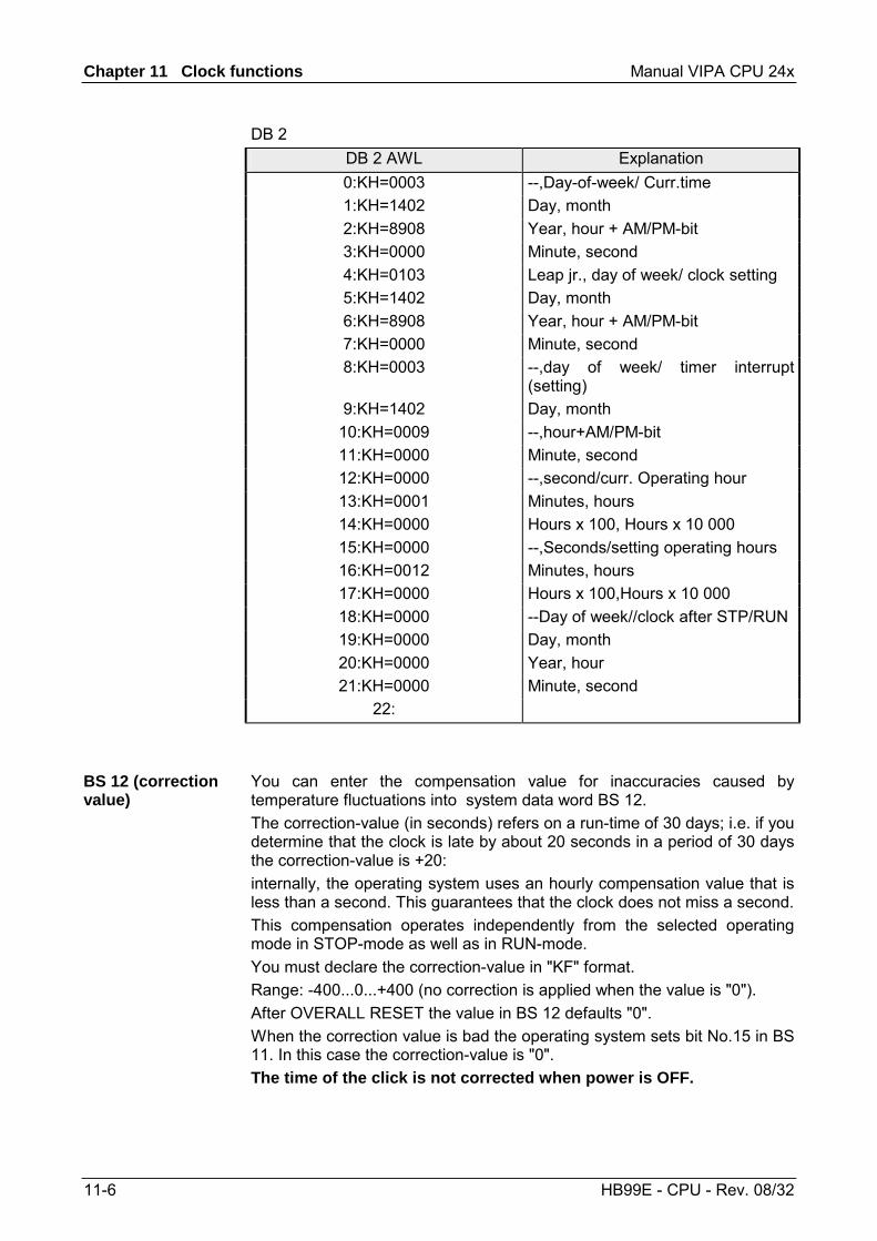
Chapter 11 Clock functions Manual VIPA CPU 24x
11-6 HB99E - CPU - Rev. 08/32
DB 2 DB 2 AWL Explanation 0:KH=0003 --,Day-of-week/ Curr.time 1:KH=1402 Day, month 2:KH=8908 Year, hour + AM/PM-bit 3:KH=0000 Minute, second 4:KH=0103 Leap jr., day of week/ clock setting 5:KH=1402 Day, month 6:KH=8908 Year, hour + AM/PM-bit 7:KH=0000 Minute, second 8:KH=0003 --,day of week/ timer interrupt
(setting) 9:KH=1402 Day, month
10:KH=0009 --,hour+AM/PM-bit 11:KH=0000 Minute, second 12:KH=0000 --,second/curr. Operating hour 13:KH=0001 Minutes, hours 14:KH=0000 Hours x 100, Hours x 10 000 15:KH=0000 --,Seconds/setting operating hours 16:KH=0012 Minutes, hours 17:KH=0000 Hours x 100,Hours x 10 000 18:KH=0000 --Day of week//clock after STP/RUN 19:KH=0000 Day, month 20:KH=0000 Year, hour 21:KH=0000 Minute, second
22:
You can enter the compensation value for inaccuracies caused by temperature fluctuations into system data word BS 12. The correction-value (in seconds) refers on a run-time of 30 days; i.e. if you determine that the clock is late by about 20 seconds in a period of 30 days the correction-value is +20: internally, the operating system uses an hourly compensation value that is less than a second. This guarantees that the clock does not miss a second. This compensation operates independently from the selected operating mode in STOP-mode as well as in RUN-mode. You must declare the correction-value in "KF" format. Range: -400...0...+400 (no correction is applied when the value is "0"). After OVERALL RESET the value in BS 12 defaults "0". When the correction value is bad the operating system sets bit No.15 in BS 11. In this case the correction-value is "0". The time of the click is not corrected when power is OFF.
BS 12 (correction value)

Manual VIPA CPU 24x Chapter 11 Clock functions
HB99E - CPU - Rev. 08/32 11-7
Structure of the clock data area
The location of the clock data area must be stored in system-data BS 8 and BS 9. Data is exchanged between control-program and the integrated clock via the clock data area. The integrated clock stores the current time, the date and the current contents of the operating time counter in the clock data area (flag-area or data-block). The settings for the alarm function and the operating time counter are also saved into the same clock data area by the control-program. The control program only can read or write clock data area, but it can never access the clock directly. The following illustration shows this operation.
Current time/Current date(word 0 to 3)
Time/datesettings(word 4 to 7)
Alarm time(word 8 to 11)
Currentoperating time(word 12 to 14)
Settings operatingtime counter(word 15 to 17)
Time/date of thelast RUN-STOPtransition(word 18 to 21)
Clock data area
Controlprogram
Integratedclock
Reas clock data by meansof load operations
Transfer settings by meansof transfer operations
Write clock datainto clock data area
Clock accepts settings from clock data area
To set the clock you only need to supply the data that is required by the respective function. For instance, if you only want to modify the data for the clock function, you do not need to specify the data for the alarm function or for the operating time counter.
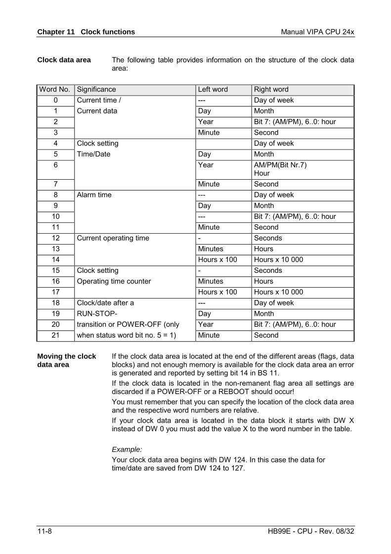
Chapter 11 Clock functions Manual VIPA CPU 24x
11-8 HB99E - CPU - Rev. 08/32
The following table provides information on the structure of the clock data area:
Word No. Significance Left word Right word 0 Current time / --- Day of week 1 Current data Day Month 2 Year Bit 7: (AM/PM), 6..0: hour 3 Minute Second 4 Clock setting Day of week 5 Time/Date Day Month 6 Year AM/PM(Bit Nr.7)
Hour 7 Minute Second 8 Alarm time --- Day of week 9 Day Month
10 --- Bit 7: (AM/PM), 6..0: hour 11 Minute Second 12 Current operating time - Seconds 13 Minutes Hours 14 Hours x 100 Hours x 10 000 15 Clock setting - Seconds 16 Operating time counter Minutes Hours 17 Hours x 100 Hours x 10 000 18 Clock/date after a --- Day of week 19 RUN-STOP- Day Month 20 transition or POWER-OFF (only Year Bit 7: (AM/PM), 6..0: hour 21 when status word bit no. 5 = 1) Minute Second
If the clock data area is located at the end of the different areas (flags, data blocks) and not enough memory is available for the clock data area an error is generated and reported by setting bit 14 in BS 11. If the clock data is located in the non-remanent flag area all settings are discarded if a POWER-OFF or a REBOOT should occur! You must remember that you can specify the location of the clock data area and the respective word numbers are relative. If your clock data area is located in the data block it starts with DW X instead of DW 0 you must add the value X to the word number in the table. Example: Your clock data area begins with DW 124. In this case the data for time/date are saved from DW 124 to 127.
Clock data area
Moving the clock data area

Manual VIPA CPU 24x Chapter 11 Clock functions
HB99E - CPU - Rev. 08/32 11-9
Note the following: • The entries in the clock data area are decimal entries, i.e. they must be
stated in BCD-coded form. Data-format "KZ" loads a BCD-coded constant into AKKU 1 and therefore it is particularly suitable for specifying clock data.
• The clock manages leap years automatically. • You can choose whether your clock should operate in 12-hour or in 24-
hour mode by means of bit 1 in the status-word. The AM/PM-flag (0 = AM; 1 = PM) is only important in the 12-hour mode of the hardware clock. It corresponds to bit 7 of the following words. Word 2, word 6, word 10, word 20.
• In this operating mode the hours and the AM/PM flag can not be set independent of one another when the clock is being set.
• In 24-hour-mode the AM/PM-flag of the clock is tested when the clock or the alarm is being set and it will set the respective error-bit.
The settings for the clock must be located within the specified definition areas shown in the following table:
Size valid parameter size valid parameter Seconds 0...59 Day 1...31 Minutes 0...59 Month 1...12 Hours in 24h mode: Year 0...99
0...23 for AM 1...12 (12=0 hours) for PM 81...92 (92=12 noon) with AM/PM-Bit) 0...99 when operating time counter is set
Day of week 0...7 1 = Sunday 2 = Monday 3 = Tuesday 4 = Wednesday 5 = Thursday 6 = Friday 7 = Saturday
Features
Definition area for settings
Chapter 11 Clock functions Manual VIPA CPU 24x
11-10 HB99E - CPU - Rev. 08/32
Structure of the status word
On the one hand the status word can be interrogated to detect errors when setting the clock, on the other hand a change of certain bits of the status word can be used to disable or enable specific transfer or read operations. Furthermore the behavior of the clock when the CPU changes from RUN- to STOP mode or for POWER-OFF can be defined by means of the respective bits (flags). The status-word can be located in the flag area or in a data block. The location must be determined in BS 9 and BS 10 in the system data. The bits of the status word are: - Clock flags - Operating system flags - Operating time counter flags, - Alarm flags.
The "transfer settings" bits (bit No. 2, 10, 14 of the status word) are reset by the operating system if: - the settings were transferred, - the settings were not transferred since they were outside the valid range.
In this case the respective error bit is also set (bit No. 0, 8, 12 of the status word).
The "transfer settings" bits (bit No. 2, 10, 14 of the status word) are not reset by the operating system if: - the system data for the clock is incorrect or it do not exist - the clock data area is too small - the clock is defective (hardware error).
In a data block you can test the different bits of the data word by means of the operation "P<data-word-number> <bit-number>". In the flag area you can test the different bits by specifying the <byte-address> and the <bit number>. Example: The status word is stored in DW 13. You want to test, whether the pre-set alarm time was reached. The test is conducted by means of the instruction "P D 13.13 " If the status word was stored in MW 13 the same test is written as "U M 13.5"
Function
Setting/resetting bits
Testing the status word
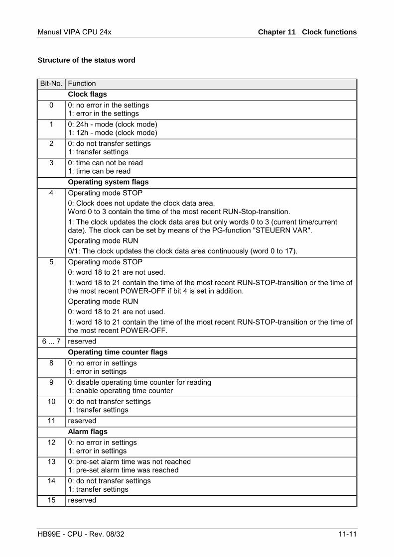
Manual VIPA CPU 24x Chapter 11 Clock functions
HB99E - CPU - Rev. 08/32 11-11
Structure of the status word
Bit-No. Function Clock flags
0 0: no error in the settings 1: error in the settings
1 0: 24h - mode (clock mode) 1: 12h - mode (clock mode)
2 0: do not transfer settings 1: transfer settings
3 0: time can not be read 1: time can be read
Operating system flags 4 Operating mode STOP
0: Clock does not update the clock data area. Word 0 to 3 contain the time of the most recent RUN-Stop-transition. 1: The clock updates the clock data area but only words 0 to 3 (current time/current date). The clock can be set by means of the PG-function "STEUERN VAR". Operating mode RUN 0/1: The clock updates the clock data area continuously (word 0 to 17).
5 Operating mode STOP 0: word 18 to 21 are not used. 1: word 18 to 21 contain the time of the most recent RUN-STOP-transition or the time of the most recent POWER-OFF if bit 4 is set in addition. Operating mode RUN 0: word 18 to 21 are not used. 1: word 18 to 21 contain the time of the most recent RUN-STOP-transition or the time of the most recent POWER-OFF.
6 ... 7 reserved Operating time counter flags
8 0: no error in settings 1: error in settings
9 0: disable operating time counter for reading 1: enable operating time counter
10 0: do not transfer settings 1: transfer settings
11 reserved Alarm flags
12 0: no error in settings 1: error in settings
13 0: pre-set alarm time was not reached 1: pre-set alarm time was reached
14 0: do not transfer settings 1: transfer settings
15 reserved
Chapter 11 Clock functions Manual VIPA CPU 24x
11-12 HB99E - CPU - Rev. 08/32
Setting and reading the clock
After you have stored your settings in the clock data area you initiate the transfer of these settings by means of bit 2 of the status word.
If you want to prevent changing the current value when you are setting the clock (alarm or operating time counter) you must enter "FFh" for the respective value.
When a setting exceeds the range of definition error message is generated that is available in a status word. The clock continues with the original values. The error message is reset as soon as the error is corrected.
To determine the word address if your clock data area is located in the flag area you must multiply the word no. specified in the clock data area table with the factor 2. If your clock data area does not start with MW 0 you must add this value also. Example: You store the clock data area in the operand section flags from MW 0. Consequently the data for the operating time counter is stored from the address in MW 24. The current data is stored in the first four data words of the clock data area. From there the information can be retrieved by means of load operations. In order to read the correct time bit 3 of the status word of the control program must be set before the read command is issued. The clock data area is no longer updated when bit 3 is set. When you have read the clock you must reset the bit again. Set bit 3 ⇒⇒⇒⇒ Read time ⇒⇒⇒⇒ Reset bit 3!
Transfer settings
Do not transfer settings
Reaction to incorrect entries
Clock data in flag area
Read current time / current date
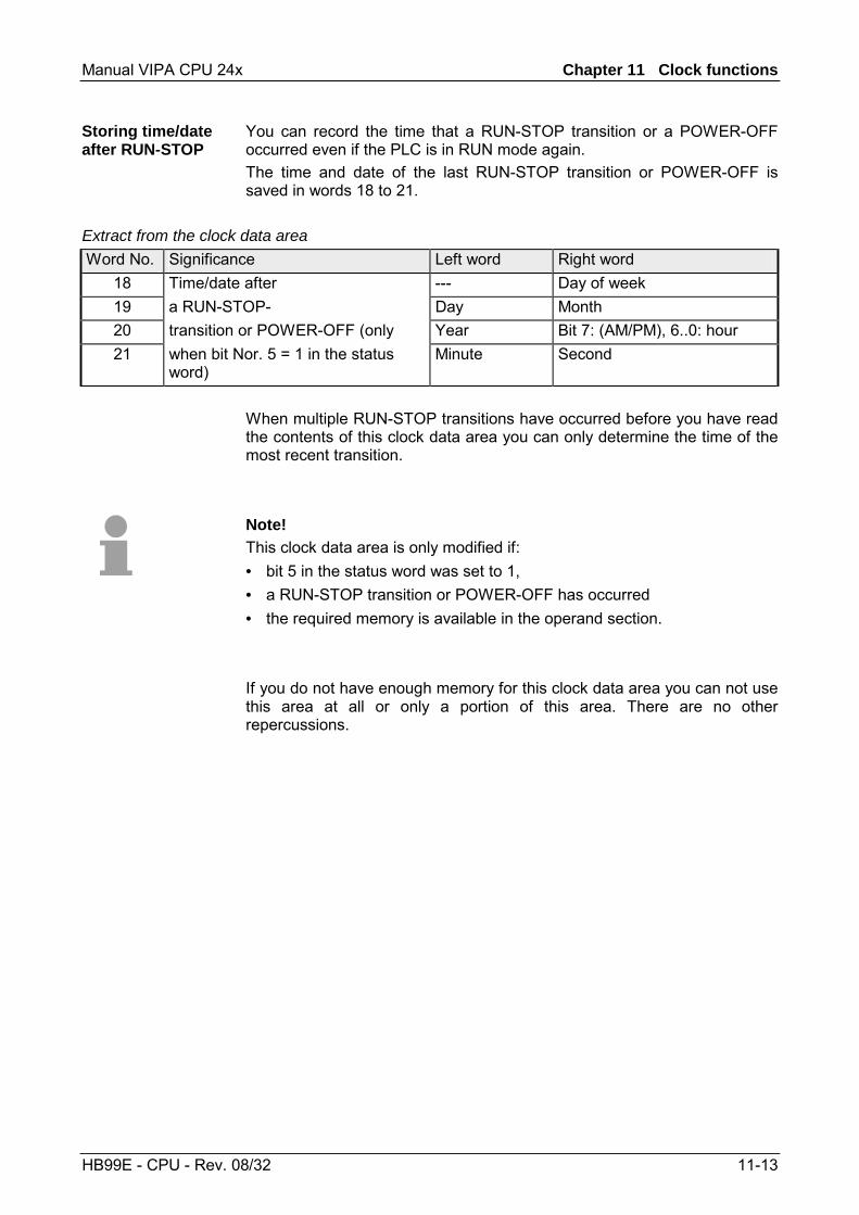
Manual VIPA CPU 24x Chapter 11 Clock functions
HB99E - CPU - Rev. 08/32 11-13
You can record the time that a RUN-STOP transition or a POWER-OFF occurred even if the PLC is in RUN mode again. The time and date of the last RUN-STOP transition or POWER-OFF is saved in words 18 to 21.
Extract from the clock data area Word No. Significance Left word Right word
18 Time/date after --- Day of week 19 a RUN-STOP- Day Month 20 transition or POWER-OFF (only Year Bit 7: (AM/PM), 6..0: hour 21 when bit Nor. 5 = 1 in the status
word) Minute Second
When multiple RUN-STOP transitions have occurred before you have read the contents of this clock data area you can only determine the time of the most recent transition.
Note! This clock data area is only modified if: • bit 5 in the status word was set to 1, • a RUN-STOP transition or POWER-OFF has occurred • the required memory is available in the operand section.
If you do not have enough memory for this clock data area you can not use this area at all or only a portion of this area. There are no other repercussions.
Storing time/date after RUN-STOP
Chapter 11 Clock functions Manual VIPA CPU 24x
11-14 HB99E - CPU - Rev. 08/32
The clock should be set to the following time/date: Tu 01.03.88; 12.00.00. The status word occupies flag word 10 and the clock data is stored in DB 2 starting at data word 0. The settings for the clock data is transferred: • by means of the PG-function "STEUERN VAR", when the PLC is in
"RUN" mode, • by means of the PG-function "STEUERN VAR", when the PLC is in
"STOP" mode and status word bit 4 =1.
Note! In case of "STEUERN VAR" you must first specify the clock data and the status word last.
Clock data area is located in DB2 Operand Signal status Significance DB2 DW 4 KH=0003 Day of week (Tuesday) DW 5 KH=0103 Date (01) and month (03) DW 6 KH=8812 Year (88) and hour (12) DW 7 KH=0000 Minute (00) and second (00) MW 10 KH=0014 In "STOP" and "RUN":
Bit 4=1: clock data area is updates in "STOP"
or Bit 2=1: transfer settings, only in "RUN":
MW 10 KH=0004 Bit 4=0: clock data is not updated in "STOP" mode. Bit 2=1: transfer settings
Example: Setting time and date

Manual VIPA CPU 24x Chapter 11 Clock functions
HB99E - CPU - Rev. 08/32 11-15
Depending on input 12.1 the settings for time and date are accepted. You must transfer these settings into marker bytes 120 to 127 before setting input 12.1. Quantities that should not be changed must be set to FFh. Input 14.0 can be used to change the mode of the clock (1=12-hour-mode). Input 13.0 is the AM/PM-bit that used by the 12-hour-mode of the clock. The clock data area is located in DB 2 starting at DW 0, the status-word is MW 10. OB 1 OB 1 AWL Explanation Setting time and date
First the settings for time and date must be transferred into MB 121 to MB 127
:U E 12.1 Trigger the setting of time/data by setting M 20.0
:S M 20.0 (this is reset in FB10) : :SPA FB 10 NAME :UHR-STEL WOTG :MB 121 Day of week TAG :MB 122 Day MON :MB 123 Month JAHR :MB 124 Year STD :MB 125 Hour AMPM :E 13.0 AM/PM-Bit (12-h-Modus) MIN :MB 126 Minutes SEK :MB 127 Seconds FEHL :M 12.1 Error bit MODE :E 14.0 12h-Mode: E 14.0 =1 :BE
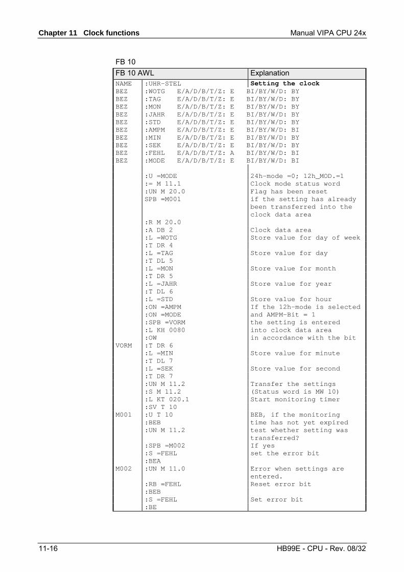
Chapter 11 Clock functions Manual VIPA CPU 24x
11-16 HB99E - CPU - Rev. 08/32
FB 10 FB 10 AWL Explanation NAME :UHR-STEL Setting the clock BEZ :WOTG E/A/D/B/T/Z: E BI/BY/W/D: BY BEZ :TAG E/A/D/B/T/Z: E BI/BY/W/D: BY BEZ :MON E/A/D/B/T/Z: E BI/BY/W/D: BY BEZ :JAHR E/A/D/B/T/Z: E BI/BY/W/D: BY BEZ :STD E/A/D/B/T/Z: E BI/BY/W/D: BY BEZ :AMPM E/A/D/B/T/Z: E BI/BY/W/D: BI BEZ :MIN E/A/D/B/T/Z: E BI/BY/W/D: BY BEZ :SEK E/A/D/B/T/Z: E BI/BY/W/D: BY BEZ :FEHL E/A/D/B/T/Z: A BI/BY/W/D: BI BEZ :MODE E/A/D/B/T/Z: E BI/BY/W/D: BI :U =MODE 24h-mode =0; 12h_MOD.=1 := M 11.1 Clock mode status word :UN M 20.0 Flag has been reset SPB =M001 if the setting has already
been transferred into the clock data area
:R M 20.0 :A DB 2 Clock data area :L =WOTG Store value for day of week :T DR 4 :L =TAG Store value for day :T DL 5 :L =MON Store value for month :T DR 5 :L =JAHR Store value for year :T DL 6 :L =STD Store value for hour :ON =AMPM If the 12h-mode is selected :ON =MODE and AMPM-Bit = 1 :SPB =VORM the setting is entered :L KH 0080 into clock data area :OW in accordance with the bit VORM :T DR 6 :L =MIN Store value for minute :T DL 7 :L =SEK Store value for second :T DR 7 :UN M 11.2 Transfer the settings :S M 11.2 (Status word is MW 10) :L KT 020.1 Start monitoring timer :SV T 10 M001 :U T 10 BEB, if the monitoring :BEB time has not yet expired :UN M 11.2 test whether setting was
transferred? :SPB =M002 If yes :S =FEHL set the error bit :BEA M002 :UN M 11.0 Error when settings are
entered. :RB =FEHL Reset error bit :BEB :S =FEHL Set error bit :BE
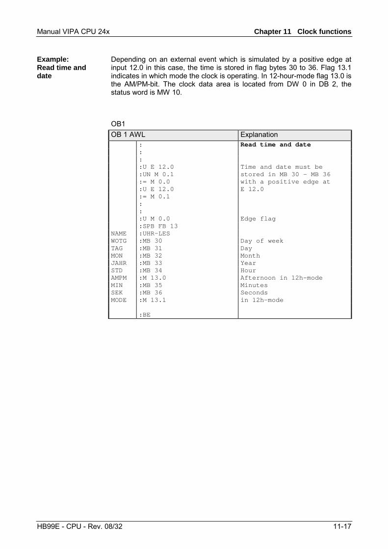
Manual VIPA CPU 24x Chapter 11 Clock functions
HB99E - CPU - Rev. 08/32 11-17
Depending on an external event which is simulated by a positive edge at input 12.0 in this case, the time is stored in flag bytes 30 to 36. Flag 13.1 indicates in which mode the clock is operating. In 12-hour-mode flag 13.0 is the AM/PM-bit. The clock data area is located from DW 0 in DB 2, the status word is MW 10.
OB1 OB 1 AWL Explanation : Read time and date : : :U E 12.0 Time and date must be :UN M 0.1 stored in MB 30 - MB 36 := M 0.0 with a positive edge at :U E 12.0 E 12.0 := M 0.1 : : :U M 0.0 Edge flag :SPB FB 13 NAME :UHR-LES WOTG :MB 30 Day of week TAG :MB 31 Day MON :MB 32 Month JAHR :MB 33 Year STD :MB 34 Hour AMPM :M 13.0 Afternoon in 12h-mode MIN :MB 35 Minutes SEK :MB 36 Seconds MODE :M 13.1 in 12h-mode :BE
Example: Read time and date

Chapter 11 Clock functions Manual VIPA CPU 24x
11-18 HB99E - CPU - Rev. 08/32
FB 13 FB 13 AWL Explanation NAME :UHR-STEL Setting the clock BEZ :WOTG E/A/D/B/T/Z: A BI/BY/W/D: BY BEZ :TAG E/A/D/B/T/Z: A BI/BY/W/D: BY BEZ :MON E/A/D/B/T/Z: A BI/BY/W/D: BY BEZ :JAHR E/A/D/B/T/Z: A BI/BY/W/D: BY BEZ :STD E/A/D/B/T/Z: A BI/BY/W/D: BY BEZ :AMPM E/A/D/B/T/Z: A BI/BY/W/D: BI BEZ :MIN E/A/D/B/T/Z: A BI/BY/W/D: BY BEZ :SEK E/A/D/B/T/Z: A BI/BY/W/D: BY BEZ :MODE E/A/D/B/T/Z: A BI/BY/W/D: BI :UN M 11.3 The time can be read :S M 11.3 (set bit 3 in status word :A DB 2 :L DR 0 Day of week :T =WOTG :L DL 1 Day :T =TAG :L DR 1 Month :T =MON :L DL 2 Year :T =JAHR :L DR 2 Hour :L KH 007F Mask out AMPM-bit :UW only used for 12h-mode :T =STD P D 2.7 Display AMPM-bit := =AMPM only relevant for 12h-mode :L DL 3 Minute :T =MIN :L DR 3 Second :T =SEK :U M 11.3 Time is updated :R M 11.3 :U M 11.1 Display clock-mode := =MODE Mode=1, for 12h-mode :BE
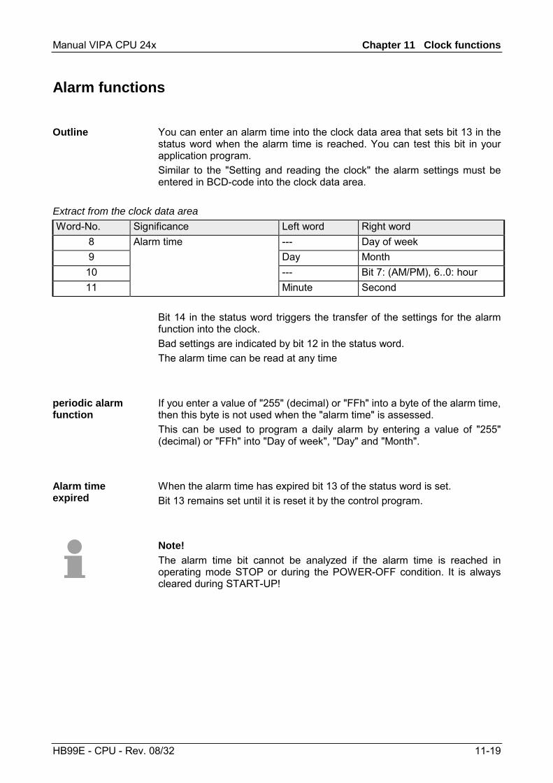
Manual VIPA CPU 24x Chapter 11 Clock functions
HB99E - CPU - Rev. 08/32 11-19
Alarm functions
You can enter an alarm time into the clock data area that sets bit 13 in the status word when the alarm time is reached. You can test this bit in your application program. Similar to the "Setting and reading the clock" the alarm settings must be entered in BCD-code into the clock data area.
Extract from the clock data area Word-No. Significance Left word Right word
8 Alarm time --- Day of week 9 Day Month 10 --- Bit 7: (AM/PM), 6..0: hour 11 Minute Second
Bit 14 in the status word triggers the transfer of the settings for the alarm function into the clock. Bad settings are indicated by bit 12 in the status word. The alarm time can be read at any time
If you enter a value of "255" (decimal) or "FFh" into a byte of the alarm time, then this byte is not used when the "alarm time" is assessed. This can be used to program a daily alarm by entering a value of "255" (decimal) or "FFh" into "Day of week", "Day" and "Month".
When the alarm time has expired bit 13 of the status word is set. Bit 13 remains set until it is reset it by the control program.
Note! The alarm time bit cannot be analyzed if the alarm time is reached in operating mode STOP or during the POWER-OFF condition. It is always cleared during START-UP!
Outline
periodic alarm function
Alarm time expired
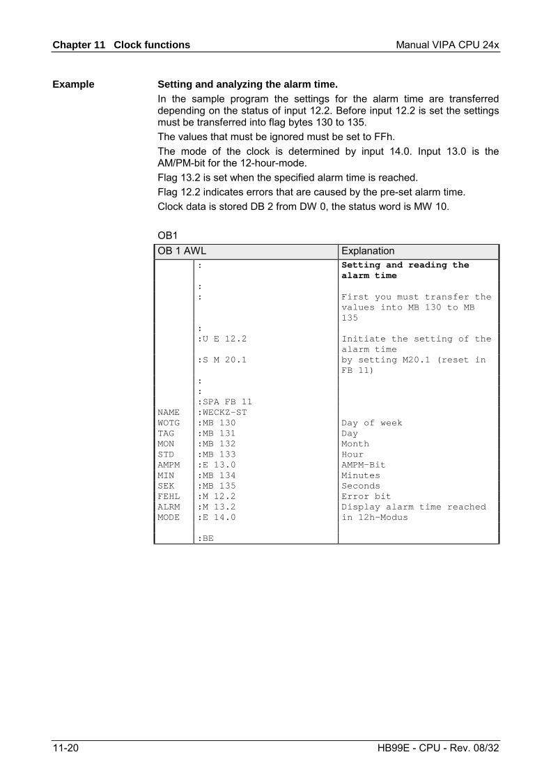
Chapter 11 Clock functions Manual VIPA CPU 24x
11-20 HB99E - CPU - Rev. 08/32
Setting and analyzing the alarm time. In the sample program the settings for the alarm time are transferred depending on the status of input 12.2. Before input 12.2 is set the settings must be transferred into flag bytes 130 to 135. The values that must be ignored must be set to FFh. The mode of the clock is determined by input 14.0. Input 13.0 is the AM/PM-bit for the 12-hour-mode. Flag 13.2 is set when the specified alarm time is reached. Flag 12.2 indicates errors that are caused by the pre-set alarm time. Clock data is stored DB 2 from DW 0, the status word is MW 10. OB1 OB 1 AWL Explanation : Setting and reading the
alarm time : : First you must transfer the
values into MB 130 to MB 135
: :U E 12.2 Initiate the setting of the
alarm time :S M 20.1 by setting M20.1 (reset in
FB 11) : : :SPA FB 11 NAME :WECKZ-ST WOTG :MB 130 Day of week TAG :MB 131 Day MON :MB 132 Month STD :MB 133 Hour AMPM :E 13.0 AMPM-Bit MIN :MB 134 Minutes SEK :MB 135 Seconds FEHL :M 12.2 Error bit ALRM :M 13.2 Display alarm time reached MODE :E 14.0 in 12h-Modus :BE
Example
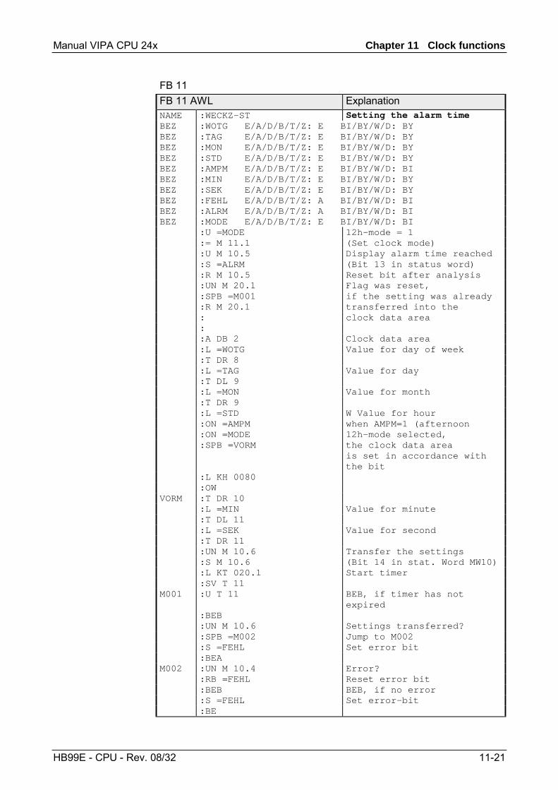
Manual VIPA CPU 24x Chapter 11 Clock functions
HB99E - CPU - Rev. 08/32 11-21
FB 11 FB 11 AWL Explanation NAME :WECKZ-ST Setting the alarm time BEZ :WOTG E/A/D/B/T/Z: E BI/BY/W/D: BY BEZ :TAG E/A/D/B/T/Z: E BI/BY/W/D: BY BEZ :MON E/A/D/B/T/Z: E BI/BY/W/D: BY BEZ :STD E/A/D/B/T/Z: E BI/BY/W/D: BY BEZ :AMPM E/A/D/B/T/Z: E BI/BY/W/D: BI BEZ :MIN E/A/D/B/T/Z: E BI/BY/W/D: BY BEZ :SEK E/A/D/B/T/Z: E BI/BY/W/D: BY BEZ :FEHL E/A/D/B/T/Z: A BI/BY/W/D: BI BEZ :ALRM E/A/D/B/T/Z: A BI/BY/W/D: BI BEZ :MODE E/A/D/B/T/Z: E BI/BY/W/D: BI :U =MODE 12h-mode = 1 := M 11.1 (Set clock mode) :U M 10.5 Display alarm time reached :S =ALRM (Bit 13 in status word) :R M 10.5 Reset bit after analysis :UN M 20.1 Flag was reset, :SPB =M001 if the setting was already :R M 20.1 transferred into the : clock data area : :A DB 2 Clock data area :L =WOTG Value for day of week :T DR 8 :L =TAG Value for day :T DL 9 :L =MON Value for month :T DR 9 :L =STD W Value for hour :ON =AMPM when AMPM=1 (afternoon :ON =MODE 12h-mode selected, :SPB =VORM the clock data area is set in accordance with the bit :L KH 0080 :OW VORM :T DR 10 :L =MIN Value for minute :T DL 11 :L =SEK Value for second :T DR 11 :UN M 10.6 Transfer the settings :S M 10.6 (Bit 14 in stat. Word MW10) :L KT 020.1 Start timer :SV T 11 M001 :U T 11 BEB, if timer has not
expired :BEB :UN M 10.6 Settings transferred? :SPB =M002 Jump to M002 :S =FEHL Set error bit :BEA M002 :UN M 10.4 Error? :RB =FEHL Reset error bit :BEB BEB, if no error :S =FEHL Set error-bit :BE
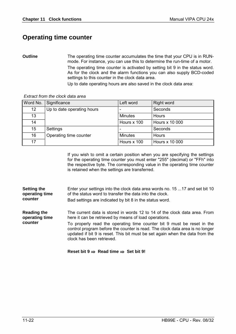
Chapter 11 Clock functions Manual VIPA CPU 24x
11-22 HB99E - CPU - Rev. 08/32
Operating time counter
The operating time counter accumulates the time that your CPU is in RUN-mode. For instance, you can use this to determine the run-time of a motor. The operating time counter is activated by setting bit 9 in the status word. As for the clock and the alarm functions you can also supply BCD-coded settings to this counter in the clock data area. Up to date operating hours are also saved in the clock data area:
Extract from the clock data area Word No. Significance Left word Right word
12 Up to date operating hours - Seconds 13 Minutes Hours 14 Hours x 100 Hours x 10 000 15 Settings - Seconds 16 Operating time counter Minutes Hours 17 Hours x 100 Hours x 10 000
If you wish to omit a certain position when you are specifying the settings for the operating time counter you must enter "255" (decimal) or "FFh" into the respective byte. The corresponding value in the operating time counter is retained when the settings are transferred.
Enter your settings into the clock data area words no. 15 ...17 and set bit 10 of the status word to transfer the data into the clock. Bad settings are indicated by bit 8 in the status word. The current data is stored in words 12 to 14 of the clock data area. From here it can be retrieved by means of load operations. To properly read the operating time counter bit 9 must be reset in the control program before the counter is read. The clock data area is no longer updated if bit 9 is reset. This bit must be set again when the data from the clock has been retrieved. Reset bit 9 ⇒⇒⇒⇒ Read time ⇒⇒⇒⇒ Set bit 9!
Outline
Setting the operating time counter
Reading the operating time counter

Manual VIPA CPU 24x Chapter 11 Clock functions
HB99E - CPU - Rev. 08/32 11-23
The settings for the operating time counter must be retrieved depending on the status of input 12.3. These values must be transferred into flag bytes 136 to 140 before input 12.3 is set (not included in the example). Values that should not be modified must be set to FFh. Flag 12.3 indicates errors in the entered settings. The clock data area is located from DW0 in DB 2, the status-word is MW 10. OB 1 OB 1 AWL Explanation : setting the operating time
counter : : Transfer the values into MB
136 to MB 140 : :U E 12.3 Trigger the transfer of the
settings for the operating time counter
:S M 20.2 by setting M20.2 : : :SPA FB 12 NAME :BETRST-S SEK :MB 136 Seconds MIN :MB 137 Minutes STD0 :MB 138 Hours STD2 :MB 139 Hours x 100 STD4 :MB 140 Hours x 10000 FEHL :M 12.3 Error bit :BE
Example: Setting the operating time counter

Chapter 11 Clock functions Manual VIPA CPU 24x
11-24 HB99E - CPU - Rev. 08/32
FB 12 FB 12 AWL Explanation NAME :BETRST-S Setting the operating time
counter BEZ :SEK E/A/D/B/T/Z: E BI/BY/W/D: BY BEZ :MIN E/A/D/B/T/Z: E BI/BY/W/D: BY BEZ :STD0 E/A/D/B/T/Z: E BI/BY/W/D: BY BEZ :STD2 E/A/D/B/T/Z: E BI/BY/W/D: BY BEZ :STD4 E/A/D/B/T/Z: E BI/BY/W/D: BY BEZ :FEHL E/A/D/B/T/Z: A BI/BY/W/D: BI :UN M 20.2 Flag is reset, :SPB =M001 if the setting was already
transferred into the clock data area
:R M 20.2 : :A DB 2 Clock data area :L =SEK Value for seconds :T DR 15 :L =MIN Value for minutes :T DL 16 :L =STD0 Value for hours :T DR 16 :L =STD2 Value for hours x 100 :T DL 17 :L STD4 Value for hours x 10000 :T DR 17 :UN M 10.2 Transfer the settings :S M 10.2 Bit 10 status word MW 10 :S M 10.1 Release operating time counter, if it has not been released as yet. :L KT 020.1 Start monitoring timer :SV T 12 M001 :U T 12 BEB, if timer has not :BEB expired :UN M 10.2 if settings were transf. :SPB =M002 jump to M002 :S =FEHL Set error-bit :BEA M002 :UN M 10.0 Error in settings :RB =FEHL Reset error bit :BEB BEB, if error did not occur :S =FEHL Set error-bit :BE
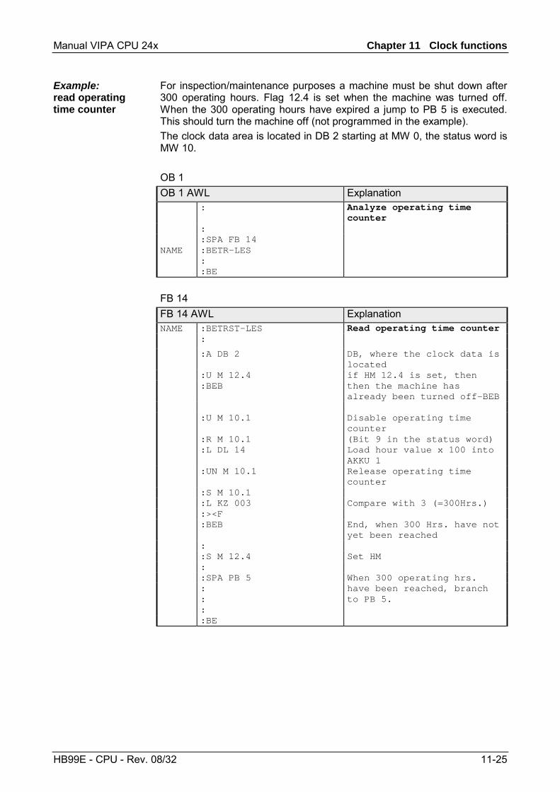
Manual VIPA CPU 24x Chapter 11 Clock functions
HB99E - CPU - Rev. 08/32 11-25
For inspection/maintenance purposes a machine must be shut down after 300 operating hours. Flag 12.4 is set when the machine was turned off. When the 300 operating hours have expired a jump to PB 5 is executed. This should turn the machine off (not programmed in the example). The clock data area is located in DB 2 starting at MW 0, the status word is MW 10. OB 1 OB 1 AWL Explanation : Analyze operating time
counter : :SPA FB 14 NAME :BETR-LES : :BE
FB 14 FB 14 AWL Explanation NAME :BETRST-LES Read operating time counter : :A DB 2 DB, where the clock data is
located :U M 12.4 if HM 12.4 is set, then :BEB then the machine has
already been turned off-BEB :U M 10.1 Disable operating time
counter :R M 10.1 (Bit 9 in the status word) :L DL 14 Load hour value x 100 into
AKKU 1 :UN M 10.1 Release operating time
counter :S M 10.1 :L KZ 003 Compare with 3 (=300Hrs.) :><F :BEB End, when 300 Hrs. have not
yet been reached : :S M 12.4 Set HM : :SPA PB 5 When 300 operating hrs. : have been reached, branch : to PB 5. : :BE
Example: read operating time counter

Chapter 11 Clock functions Manual VIPA CPU 24x
11-26 HB99E - CPU - Rev. 08/32
Manual VIPA CPU 24x Chapter 12 Alarm and timer controlled processing
HB99E - CPU - Rev. 08/32 12-1
Chapter 12 Alarm and timer controlled processing
This chapter describes the program execution and interrupts to the cyclic operation of the CPU 24x.
Topic Page Chapter 12 Alarm and timer controlled processing....................... 12-1
Programming of alarm blocks............................................................. 12-2 Timer controlled program execution ................................................... 12-4 Elapsed time controlled program execution ........................................ 12-6 Priority and response time.................................................................. 12-7 Alarm diagnostic data....................................................................... 12-11
Outline
Contents
Chapter 12 Alarm and timer controlled processing Manual VIPA CPU 24x
12-2 HB99E - CPU - Rev. 08/32
Programming of alarm blocks
The system 200V supports certain modules that can trigger alarms, e.g. the VIPA Profibus master IM 208. The CPU is the station that processes these alarms. It receives these alarms and must adapt its program execution according to the conditions presented by the alarms. An alarm interrupts the operating system of the CPU, the cyclic or timer controlled program execution to call an alarm-OB: When the CPU 24x receives an alarm it issues a call to OB 2. In STOP-mode the CPU ignores all alarms.
The following asynchronous program execution methods exist in addition to the cyclic operation of the application program: • alarm controlled program execution (OB 2) • time slot controlled program execution (OB 10 ... OB 13) • time duration controlled program execution (OB 6) • alarm errors (OB 33) If the required components have not been programmed there is no reaction to the event and the program continues directly after the alarm. If additional alarms are received (an edge suffices!) an alarm-error is generated.
Additional alarms are disabled when an alarm has interrupted the current cycle, i.e. while the CPU is processing an alarm-OB. For this reason an active alarm-program cannot be interrupted. In principle, an alarm has a higher priority than "timer-alarms" (OB10 ...OB13). It is possible to define the priority of OB 6 with respect to alarm processing. An alarm interrupts the cyclic and in the timer controlled program after every operation. Integrated function blocks and operating system routines can only be interrupted by an alarm at pre-determined positions (not user definable!) If you wish to prevent interrupts in certain sections of your cyclic or time-controlled program you must protect this section by means of the "AS" (disable alarms) operation. At the end of the "protected" section you must re-enable alarms by means of the operation "AF". An alarm can be stored while alarms are inhibited!
Principles
Outline
Triggering
Protecting a program from interruption by alarms

Manual VIPA CPU 24x Chapter 12 Alarm and timer controlled processing
HB99E - CPU - Rev. 08/32 12-3
The cyclic program can be interrupted after each instruction. The system program of the CPU and the supplied function blocks can be interrupted at specific locations. The maximum possible response time depends on the function that is currently being processed. On the CPU 24x an alarm program can not be interrupted by an additional interrupt or by an elapsed time controlled alarm. An alarm error is triggered if another alarm should occur while an alarm is being processed. OB 6 has the highest priority by default.
Remember that that the block nesting depth of 32 levels also applies to calls of alarm-OBs! If you wish to use the same flags in the alarm routine as in the cyclic program you must save the contents of these flags at the start of the alarm routine, e.g. in a data block. At the end of the alarm routine you restore the saved contents of the flag-bytes (-words). Save flag-contents ⇒⇒⇒⇒ Alarm processing ⇒⇒⇒⇒ Restore flag-contents! If you access page-frame-addressed modules on the CPU 24x you must also save and restore the page frame number in the interrupt routine. The interrupt is acknowledged automatically.
While an alarm program is being executed the process image is not updated by the system program. If you wish to use the current input values or to respond quickly to an alarm via the digital outputs then the process image must be updated in the alarm program by means of L PB or T PB.
If it is required that reactions are issued to alarms in the start-up routine, then you must enable alarms at the beginning of the start-up OBs by means of the operation "AF". Otherwise the respective alarms will only become effective after the start-up OBs have been processed.
Point of interrupt
Programming hints
Process image during an alarm
Enabling alarms during the start-up phase (OB 21, OB 22)
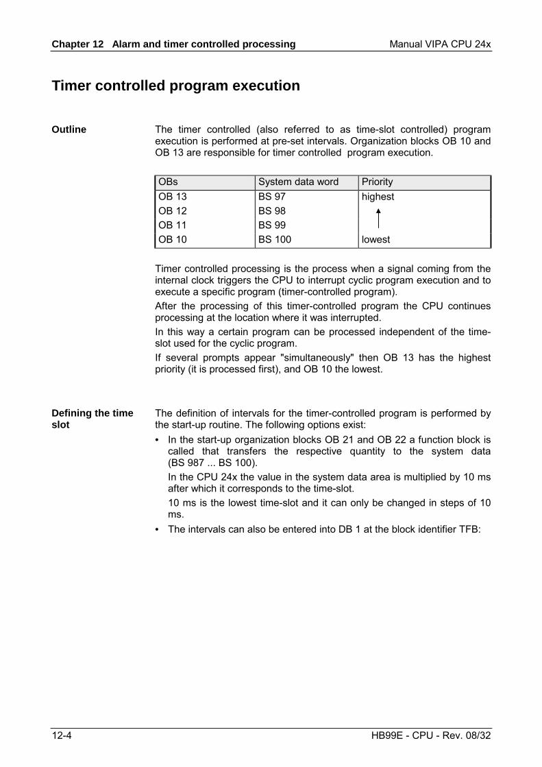
Chapter 12 Alarm and timer controlled processing Manual VIPA CPU 24x
12-4 HB99E - CPU - Rev. 08/32
Timer controlled program execution
The timer controlled (also referred to as time-slot controlled) program execution is performed at pre-set intervals. Organization blocks OB 10 and OB 13 are responsible for timer controlled program execution. OBs System data word Priority OB 13 BS 97 highest OB 12 BS 98 OB 11 BS 99 OB 10 BS 100 lowest
Timer controlled processing is the process when a signal coming from the internal clock triggers the CPU to interrupt cyclic program execution and to execute a specific program (timer-controlled program). After the processing of this timer-controlled program the CPU continues processing at the location where it was interrupted. In this way a certain program can be processed independent of the time-slot used for the cyclic program. If several prompts appear "simultaneously" then OB 13 has the highest priority (it is processed first), and OB 10 the lowest.
The definition of intervals for the timer-controlled program is performed by the start-up routine. The following options exist: • In the start-up organization blocks OB 21 and OB 22 a function block is
called that transfers the respective quantity to the system data (BS 987 ... BS 100). In the CPU 24x the value in the system data area is multiplied by 10 ms after which it corresponds to the time-slot. 10 ms is the lowest time-slot and it can only be changed in steps of 10 ms.
• The intervals can also be entered into DB 1 at the block identifier TFB:
Outline
Defining the time slot
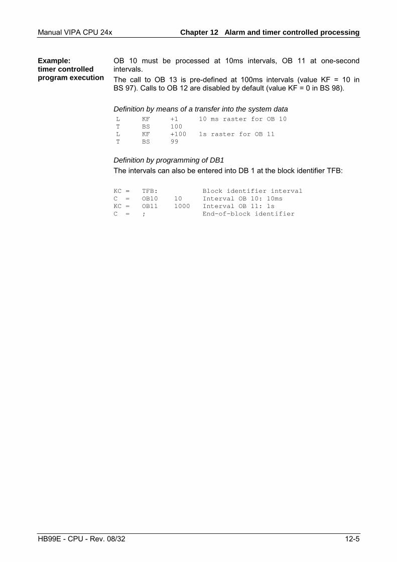
Manual VIPA CPU 24x Chapter 12 Alarm and timer controlled processing
HB99E - CPU - Rev. 08/32 12-5
OB 10 must be processed at 10ms intervals, OB 11 at one-second intervals. The call to OB 13 is pre-defined at 100ms intervals (value KF = 10 in BS 97). Calls to OB 12 are disabled by default (value KF = 0 in BS 98). Definition by means of a transfer into the system data L KF +1 10 ms raster for OB 10 T BS 100 L KF +100 1s raster for OB 11 T BS 99
Definition by programming of DB1 The intervals can also be entered into DB 1 at the block identifier TFB: KC = TFB: Block identifier interval C = OB10 10 Interval OB 10: 10ms KC = OB11 1000 Interval OB 11: 1s C = ; End-of-block identifier
Example: timer controlled program execution
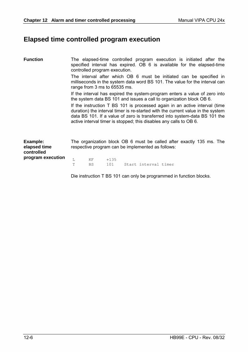
Chapter 12 Alarm and timer controlled processing Manual VIPA CPU 24x
12-6 HB99E - CPU - Rev. 08/32
Elapsed time controlled program execution
The elapsed-time controlled program execution is initiated after the specified interval has expired. OB 6 is available for the elapsed-time controlled program execution. The interval after which OB 6 must be initiated can be specified in milliseconds in the system data word BS 101. The value for the interval can range from 3 ms to 65535 ms. If the interval has expired the system-program enters a value of zero into the system data BS 101 and issues a call to organization block OB 6. If the instruction T BS 101 is processed again in an active interval (time duration) the interval timer is re-started with the current value in the system data BS 101. If a value of zero is transferred into system-data BS 101 the active interval timer is stopped; this disables any calls to OB 6.
The organization block OB 6 must be called after exactly 135 ms. The respective program can be implemented as follows: L KF +135 T BS 101 Start interval timer
Die instruction T BS 101 can only be programmed in function blocks.
Function
Example: elapsed time controlled program execution

Manual VIPA CPU 24x Chapter 12 Alarm and timer controlled processing
HB99E - CPU - Rev. 08/32 12-7
Priority and response time
For reasons of clarity, the description in the preceding sections of the possible interruptions of the cyclic program were described separately, i.e. as if they would occur at different times. If you were only using a single class of interrupt this description would suffice. Where multiple interrupts occur the type and the processing priority of the interrupt determine the sequence in which the interrupts are processed.
The following interrupt controlled program execution methods can be inserted into the cyclic program: • elapsed time controlled processing due to an interval-alarm • alarm processing triggered by interrupts • timer controlled processing due to a prompt If all interrupts should "appear simultaneously" they are processed in the sequence shown above, i.e. first the elapsed time processing (OB 6), then the alarm processing (OB 2) and finally the timer processing (OB 10 to OB 13). Within the timer processing routine organization-block OB 13 is processed first, followed by OB 12, etc. The processing sequence of elapsed-time controlled program and the alarm-controlled program can be specified. The elapsed time processing is completed before the alarm processing by default. If you wish to modify the sequence you must set system-data-bit BS 120.6 or program data-block DB 1 accordingly. This section describes the default sequence. An elapsed-time program and an alarm-program can not be interrupted. As long as a these programs are active interruption-requests are stored. Should interruption-requests are still outstanding after the processing of the elapsed-time program and the alarm-program, then the respective organization-blocks are called in the sequence specified by the processing-priority. The in the timer controlled program can be interrupted by the elapsed-time alarm and by interrupts. When the elapsed-time program and the alarm-program have been processed, the process continues with the timer-program. The timer-controlled program can not be interrupted by prompts. The CPU will ignore prompts that occur during the period when a timer-program is being executed.
Interrupt processing priority
Chapter 12 Alarm and timer controlled processing Manual VIPA CPU 24x
12-8 HB99E - CPU - Rev. 08/32
The alarm-controlled program-execution is used to provide quick reactions to an event that has occurred at the process level, quicker than the cycle-time would permit. The resulting average response time for an alarm or an interrupt is less than this value. An essential part for the reaction time to an interrupt is due to the system-program. If the central processor is currently executing the system-program and it is executing a certain function (e.g. online-functions for a programmer) the reaction time can be increased by a large amount. The reaction time to an interrupt-request for the system-program consists of a basic reaction time and an additional reaction time that depend on the function being processed at the respective time.
Since the program can be interrupted after each instruction the reaction is normally immediate. That instruction requiring the longest time is the block-transfer TNB or TNW. A more severe effect on the reaction time is normally caused by disabled interrupts since this exists for several instructions. This time is the reaction time required by the application-program to respond to an interrupt. In the CPU 24x an interrupt-processing routine cannot be interrupted by another one; for this reason a second interrupt can only be processed after the active interrupt program has been completed. Consequently, the processing time for the interrupt-routine that is active for the longest duration can also influence the reaction time. The facts described above also apply to an elapsed-time program. An elapsed-time program organization block OB 6 can also not be interrupted by an interrupt, regardless of the selected interrupt-priority. Under certain circumstances it may be necessary to include the processing time of an elapsed-time program when calculating the interrupt response time.
Response time for program interrupts
Interrupts
Manual VIPA CPU 24x Chapter 12 Alarm and timer controlled processing
HB99E - CPU - Rev. 08/32 12-9
Alarm routines executed by the CPU 24x cannot be interrupted; therefore an elapsed-time alarm can only be processed after the alarm has been processed completely. However, the priority of the elapsed-time alarm can be changed to be before that of the interrupts, so that the elapsed-time alarm is processed first when an interrupt and an elapsed-time alarm occur simultaneously.
The response time for prompts is of a far lesser importance than that of the interrupts. The main clock is not moved if the program associated with a prompt is delayed. During the next timing period the same prompt will occur at exactly the same interval so that processing occurs at a reasonably constant rate. As a matter of course, the percentage timing error in the delayed processing time is larger for the shorter periods than for the larger ones. The system program and the integrated function blocks can not be interrupted by prompts. When the system functions are active the timing interval can be extended by the sum of the basic response time of the system program and the response time of the system functions that have been initiated. Active alarm routines or an active elapsed-time routine can not be interrupted. In addition the processing priority of the interrupts and the elapsed-time alarms is higher than that of the prompts, which means that the processing time of the alarm routine and the elapsed-time routine can be important for the response to prompts. Prompts are not processed between the disable alarms "AS" and enable alarms "AF" instructions. The duration of this lockout can also influence the response time to prompts. On the CPU 24x the timer program can not be interrupted by a prompt. For this reason the runtime of the timer program with the largest execution time must be included in the response time considerations.
Elapsed-time alarm
Prompts
Chapter 12 Alarm and timer controlled processing Manual VIPA CPU 24x
12-10 HB99E - CPU - Rev. 08/32
When an elapsed time controlled or a timer controlled program is being processed and processing is requested for a second time a prompt error is issued. A prompt error is also triggered when processing is requested a second time while alarms are disabled. A prompt error issues a call to OB 33. An error code with details on the prompt error is transferred into AKKU 1: Error code in AKKU 1
Reason
1 Processing of OB 6 2 Processing of OB 13 3 Processing of OB 12 4 Processing of OB 11 5 Processing of OB 10
The response time of the cyclic program depends mostly on the cycle processing time. The processing of every interrupt of the cyclic processing (interrupts, prompts and elapsed-time alarms) extends the time between the transfer of the process images and thus the response time of the cyclic program. If the cyclic program is interrupted at a high rate it may even cause the cycle-time monitor to issue a "cycle time exceeded" warning.
Prompt errors
Response times
Manual VIPA CPU 24x Chapter 12 Alarm and timer controlled processing
HB99E - CPU - Rev. 08/32 12-11
Alarm diagnostic data
When a process or a diagnostic alarm is received the system will issue a call to OB 2. The alarm diagnostics were introduced to allow user to install many modules that issue alarms into a single system. Every alarm is accompanied by a set of diagnostic data that is stored in the BS-area. This contains details on the cause for the alarm and the related equipment. A maximum of 9 data words are set aside for the diagnostic data and these have the following structure:
Diagnostic data in the BS-area BS-word Contents BS 110 Low Address of the module (=plug-in location 1...32) BS 110 High Alarm identifier:
1h=Process alarm 2h=Diagnostic alarm 3h=Hardware error IM 208 Slave failure IM 208 Run → Stop Hardware failure
(BS 110 High = 3): BS 111 Low 01h=Diagnose
Slave failure 04h= Diagnostic stop internal error data
BS 111 High 00h... 7Fh= Station address
internal error data
BS 112 internal error data BS 113 internal error data BS 114 internal error data
Chapter 12 Alarm and timer controlled processing Manual VIPA CPU 24x
12-12 HB99E - CPU - Rev. 08/32
A prompt error will be issued when one or more process or diagnostic alarms are received while the alarm routine is busy. As usual, the prompt error has will issue a call to OB 33. The error codes that are transferred via AKKU 1 are extended in accordance with the alarm identifier.
Error code in AKKU 1 Reason 6 Processing alarm
The data of the alarm received from the lowest plug-in location is stored from BS-cells 110 and following.
Every alarm causes an interrupt in the CPU. This interrupt triggers the alarm routine by setting a system flag. The interpreter analyzes the system flag after the completion of the next instruction. The time when the interpreter processes the next instruction, however, depends on the activities that the CPU is completing at the respective time. In the ideal case the CPU is busy processing the interpreter within the cycle and the resulting delay is a maximum of one instruction cycle. However, alarms can also occur outside of the processing cycle or during the time when the CPU is busy with serial communication tasks. These can cause delays of around 100ms. The worst case can only be determined by a detailed analysis. Furthermore, the complete time required for an alarm processing cycle is influenced by the program in OB 2. Disabled alarms and elapsed time controlled processing also have a negative impact on the alarm processing time.
Loss of alarms
Time required for alarm processing

Manual VIPA CPU 24x Appendix - Statement list
HB99E - CPU - Rev. 08/32 A-1
Appendix
A Statement list Abbreviations Explanations AKKU 1 Accumulator 1 (when loading
AKKU 1 the original contents is transferred to AKKU 2)
AKKU 2 Accumulator 2 ANZ 0/ANZ 1 Result 0 / result 1 AWL Representation statement list FOOP Formal operand, an expression of a
max. of 4 characters where the first character must be a letter.
FUP STEP 5 representation function diagram (Siemens)
KOP STEP 5 representation ladder diagram (Siemens)
MARK Symbolic address of 4 characters maximum length
OV Overflow indicator. This is set when the maximum value of a number is exceeded
PAE Process image of the inputs PAA Process image of the outputs VKE Result of logical operation VKE Jdep. J ↑ /↓ N
The instruction is only executed if the VKE = “1“. The instruction is only executed if a positive/negative transition is available from VKE. The instruction is always executed.
VKE mod. J/N 1
The VKE is modified/not modified by the operation. VKE is set to "1".
VKE lim. J N
The VKE is not modified. The result can not be used in other logical operations. The VKE is refreshed by the next binary operation (but not an assignment). Depending on whether the operation modifies the VKE or not, the VKE is used in further logical operations or remains unaltered in accordance with the operation and the status of the interrogated bit.
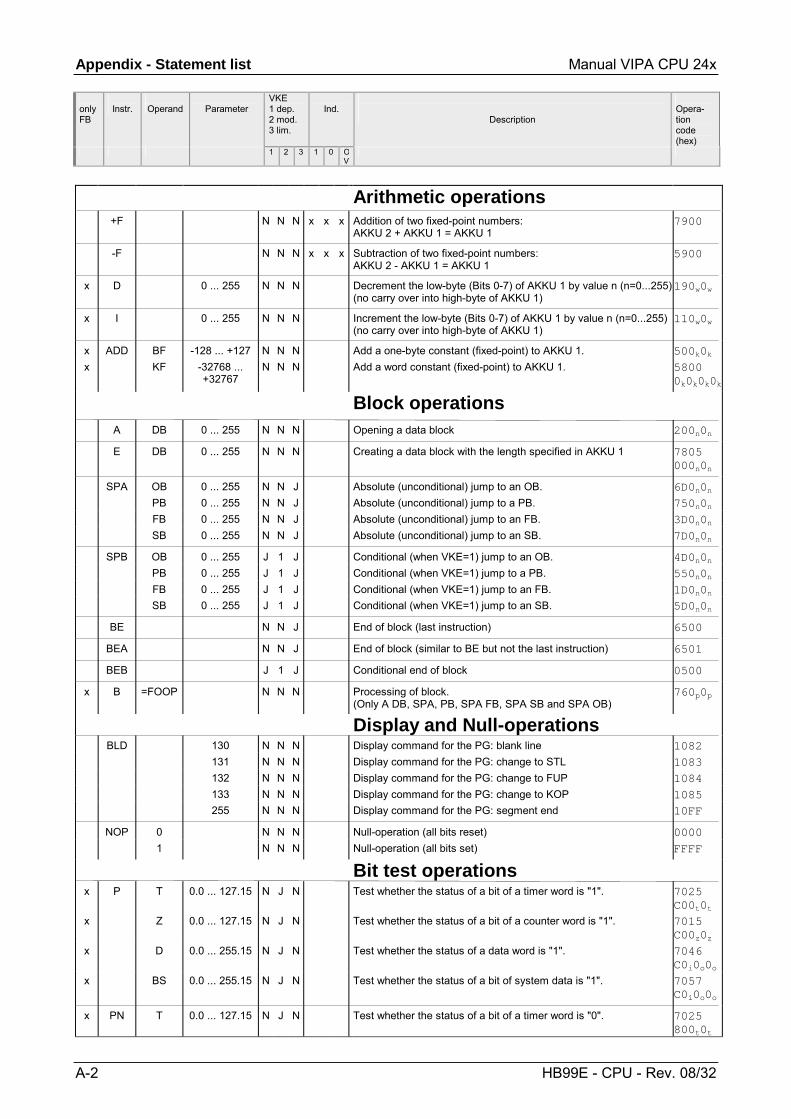
Appendix - Statement list Manual VIPA CPU 24x only FB
Instr.
Operand
Parameter
VKE 1 dep. 2 mod. 3 lim.
Ind.
Description
Opera-tion code (hex)
1 2 3 1 0 OV
A-2 HB99E - CPU - Rev. 08/32
Arithmetic operations
+F N N N x x x Addition of two fixed-point numbers: AKKU 2 + AKKU 1 = AKKU 1
7900
-F N N N x x x Subtraction of two fixed-point numbers: AKKU 2 - AKKU 1 = AKKU 1
5900
x D 0 ... 255 N N N Decrement the low-byte (Bits 0-7) of AKKU 1 by value n (n=0...255) (no carry over into high-byte of AKKU 1)
190w0w
x I 0 ... 255 N N N Increment the low-byte (Bits 0-7) of AKKU 1 by value n (n=0...255) (no carry over into high-byte of AKKU 1)
110w0w
x ADD BF -128 ... +127 N N N Add a one-byte constant (fixed-point) to AKKU 1. 500k0k
x KF -32768 ... +32767
N N N Add a word constant (fixed-point) to AKKU 1. 5800 0k0k0k0k
Block operations
A DB 0 ... 255 N N N Opening a data block 200n0n
E DB 0 ... 255 N N N Creating a data block with the length specified in AKKU 1 7805 000n0n
SPA OB 0 ... 255 N N J Absolute (unconditional) jump to an OB. 6D0n0n
PB 0 ... 255 N N J Absolute (unconditional) jump to a PB. 750n0n
FB 0 ... 255 N N J Absolute (unconditional) jump to an FB. 3D0n0n
SB 0 ... 255 N N J Absolute (unconditional) jump to an SB. 7D0n0n
SPB OB 0 ... 255 J 1 J Conditional (when VKE=1) jump to an OB. 4D0n0n
PB 0 ... 255 J 1 J Conditional (when VKE=1) jump to a PB. 550n0n
FB 0 ... 255 J 1 J Conditional (when VKE=1) jump to an FB. 1D0n0n
SB 0 ... 255 J 1 J Conditional (when VKE=1) jump to an SB. 5D0n0n
BE N N J End of block (last instruction) 6500
BEA N N J End of block (similar to BE but not the last instruction) 6501
BEB J 1 J Conditional end of block 0500
x B =FOOP N N N Processing of block. (Only A DB, SPA, PB, SPA FB, SPA SB and SPA OB)
760p0p
Display and Null-operations BLD 130 N N N Display command for the PG: blank line 1082
131 N N N Display command for the PG: change to STL 1083
132 N N N Display command for the PG: change to FUP 1084
133 N N N Display command for the PG: change to KOP 1085
255 N N N Display command for the PG: segment end 10FF
NOP 0 N N N Null-operation (all bits reset) 0000
1 N N N Null-operation (all bits set) FFFF
Bit test operations x P T 0.0 ... 127.15 N J N Test whether the status of a bit of a timer word is "1". 7025
C00t0t
x Z 0.0 ... 127.15 N J N Test whether the status of a bit of a counter word is "1". 7015 C00z0z
x D 0.0 ... 255.15 N J N Test whether the status of a data word is "1". 7046 C0i0o0o
x BS 0.0 ... 255.15 N J N Test whether the status of a bit of system data is "1". 7057 C0i0o0o
x PN T 0.0 ... 127.15 N J N Test whether the status of a bit of a timer word is "0". 7025 800t0t
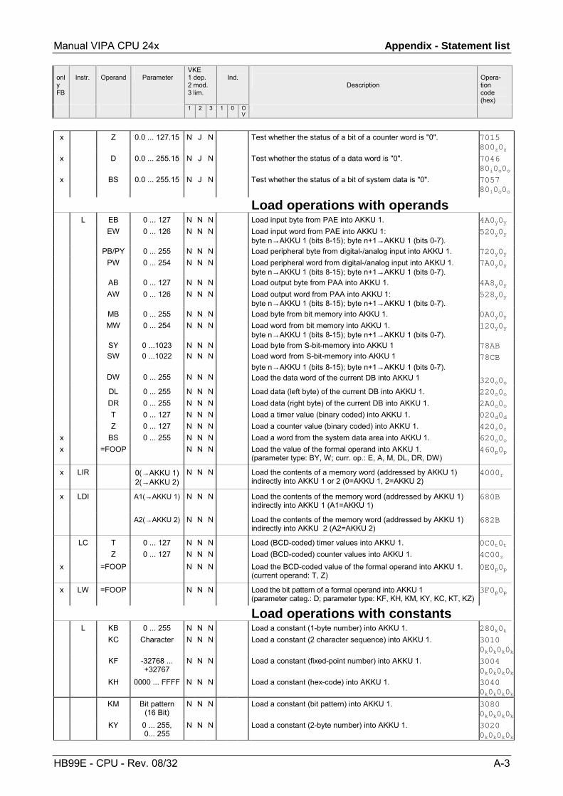
Manual VIPA CPU 24x Appendix - Statement list only FB
Instr.
Operand
Parameter
VKE 1 dep. 2 mod. 3 lim.
Ind.
Description
Opera-tion code (hex)
1 2 3 1 0 OV
HB99E - CPU - Rev. 08/32 A-3
x Z 0.0 ... 127.15 N J N Test whether the status of a bit of a counter word is "0". 7015 800z0z
x D 0.0 ... 255.15 N J N Test whether the status of a data word is "0". 7046 80i0o0o
x BS 0.0 ... 255.15 N J N Test whether the status of a bit of system data is "0". 7057 80i0o0o
Load operations with operands L EB 0 ... 127 N N N Load input byte from PAE into AKKU 1. 4A0y0y
EW 0 ... 126 N N N Load input word from PAE into AKKU 1: byte n→AKKU 1 (bits 8-15); byte n+1→AKKU 1 (bits 0-7).
520y0y
PB/PY 0 ... 255 N N N Load peripheral byte from digital-/analog input into AKKU 1. 720y0y
PW 0 ... 254 N N N Load peripheral word from digital-/analog input into AKKU 1. byte n→AKKU 1 (bits 8-15); byte n+1→AKKU 1 (bits 0-7).
7A0y0y
AB 0 ... 127 N N N Load output byte from PAA into AKKU 1. 4A8y0y
AW 0 ... 126 N N N Load output word from PAA into AKKU 1: byte n→AKKU 1 (bits 8-15); byte n+1→AKKU 1 (bits 0-7).
528y0y
MB 0 ... 255 N N N Load byte from bit memory into AKKU 1. 0A0y0y
MW 0 ... 254 N N N Load word from bit memory into AKKU 1. byte n→AKKU 1 (bits 8-15); byte n+1→AKKU 1 (bits 0-7).
120y0y
SY SW
DW
0 ...1023 0 ...1022
0 ... 255
N N
N
N N
N
N N
N
Load byte from S-bit-memory into AKKU 1 Load word from S-bit-memory into AKKU 1 byte n→AKKU 1 (bits 8-15); byte n+1→AKKU 1 (bits 0-7). Load the data word of the current DB into AKKU 1
78AB
78CB
320o0o
DL 0 ... 255 N N N Load data (left byte) of the current DB into AKKU 1. 220o0o
DR 0 ... 255 N N N Load data (right byte) of the current DB into AKKU 1. 2A0o0o
T 0 ... 127 N N N Load a timer value (binary coded) into AKKU 1. 020d0d
Z 0 ... 127 N N N Load a counter value (binary coded) into AKKU 1. 420z0z
x BS 0 ... 255 N N N Load a word from the system data area into AKKU 1. 620o0o
x =FOOP N N N Load the value of the formal operand into AKKU 1. (parameter type: BY, W; curr. op.: E, A, M, DL, DR, DW)
460p0p
x LIR 0(→AKKU 1) 2(→AKKU 2)
N N N Load the contents of a memory word (addressed by AKKU 1) indirectly into AKKU 1 or 2 (0=AKKU 1, 2=AKKU 2)
4000r
x LDI A1(→AKKU 1) N N N Load the contents of the memory word (addressed by AKKU 1) indirectly into AKKU 1 (A1=AKKU 1)
680B
A2(→AKKU 2) N N N Load the contents of the memory word (addressed by AKKU 1) indirectly into AKKU 2 (A2=AKKU 2)
682B
LC T 0 ... 127 N N N Load (BCD-coded) timer values into AKKU 1. 0C0t0t
Z 0 ... 127 N N N Load (BCD-coded) counter values into AKKU 1. 4C00z
x =FOOP N N N Load the BCD-coded value of the formal operand into AKKU 1. (current operand: T, Z)
0E0p0p
x LW =FOOP N N N Load the bit pattern of a formal operand into AKKU 1 (parameter categ.: D; parameter type: KF, KH, KM, KY, KC, KT, KZ)
3F0p0p
Load operations with constants L KB 0 ... 255 N N N Load a constant (1-byte number) into AKKU 1. 280k0k
KC Character N N N Load a constant (2 character sequence) into AKKU 1. 3010 0k0k0k0k
KF -32768 ... +32767
N N N Load a constant (fixed-point number) into AKKU 1. 3004 0k0k0k0k
KH 0000 ... FFFF N N N Load a constant (hex-code) into AKKU 1. 3040 0k0k0k0k
KM Bit pattern (16 Bit)
N N N Load a constant (bit pattern) into AKKU 1. 3080 0k0k0k0k
KY 0 ... 255, 0... 255
N N N Load a constant (2-byte number) into AKKU 1. 3020 0k0k0k0k
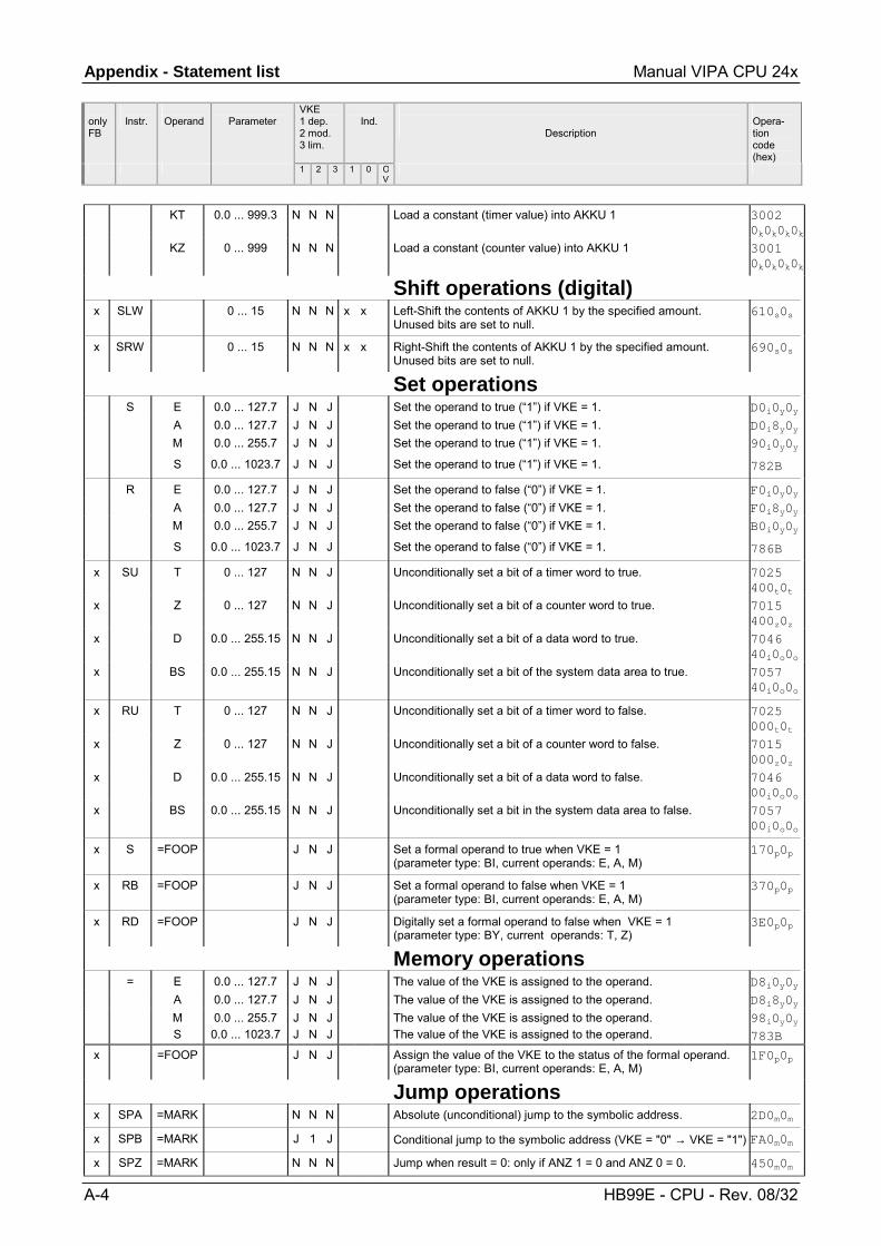
Appendix - Statement list Manual VIPA CPU 24x only FB
Instr.
Operand
Parameter
VKE 1 dep. 2 mod. 3 lim.
Ind.
Description
Opera-tion code (hex)
1 2 3 1 0 OV
A-4 HB99E - CPU - Rev. 08/32
KT 0.0 ... 999.3 N N N Load a constant (timer value) into AKKU 1 3002 0k0k0k0k
KZ 0 ... 999 N N N Load a constant (counter value) into AKKU 1 3001 0k0k0k0k
Shift operations (digital) x SLW 0 ... 15 N N N x x Left-Shift the contents of AKKU 1 by the specified amount.
Unused bits are set to null. 610s0s
x SRW 0 ... 15 N N N x x Right-Shift the contents of AKKU 1 by the specified amount. Unused bits are set to null.
690s0s
Set operations S E 0.0 ... 127.7 J N J Set the operand to true (“1”) if VKE = 1. D0i0y0y A 0.0 ... 127.7 J N J Set the operand to true (“1”) if VKE = 1. D0i8y0y M
S
0.0 ... 255.7
0.0 ... 1023.7
J
J
N
N
J
J
Set the operand to true (“1”) if VKE = 1.
Set the operand to true (“1”) if VKE = 1.
90i0y0y
782B
R E 0.0 ... 127.7 J N J Set the operand to false (“0”) if VKE = 1. F0i0y0y A 0.0 ... 127.7 J N J Set the operand to false (“0”) if VKE = 1. F0i8y0y M
S
0.0 ... 255.7
0.0 ... 1023.7
J
J
N
N
J
J
Set the operand to false (“0”) if VKE = 1.
Set the operand to false (“0”) if VKE = 1.
B0i0y0y
786B
x SU T 0 ... 127 N N J Unconditionally set a bit of a timer word to true. 7025 400t0t
x Z 0 ... 127 N N J Unconditionally set a bit of a counter word to true. 7015 400z0z
x D 0.0 ... 255.15 N N J Unconditionally set a bit of a data word to true. 7046 40i0o0o
x BS 0.0 ... 255.15 N N J Unconditionally set a bit of the system data area to true. 7057 40i0o0o
x RU T 0 ... 127 N N J Unconditionally set a bit of a timer word to false. 7025 000t0t
x Z 0 ... 127 N N J Unconditionally set a bit of a counter word to false. 7015 000z0z
x D 0.0 ... 255.15 N N J Unconditionally set a bit of a data word to false. 7046 00i0o0o
x BS 0.0 ... 255.15 N N J Unconditionally set a bit in the system data area to false. 7057 00i0o0o
x S =FOOP J N J Set a formal operand to true when VKE = 1 (parameter type: BI, current operands: E, A, M)
170p0p
x RB =FOOP J N J Set a formal operand to false when VKE = 1 (parameter type: BI, current operands: E, A, M)
370p0p
x RD =FOOP J N J Digitally set a formal operand to false when VKE = 1 (parameter type: BY, current operands: T, Z)
3E0p0p
Memory operations = E 0.0 ... 127.7 J N J The value of the VKE is assigned to the operand. D8i0y0y A 0.0 ... 127.7 J N J The value of the VKE is assigned to the operand. D8i8y0y M
S 0.0 ... 255.7 0.0 ... 1023.7
J J
N N
J J
The value of the VKE is assigned to the operand. The value of the VKE is assigned to the operand.
98i0y0y 783B
x =FOOP J N J Assign the value of the VKE to the status of the formal operand. (parameter type: BI, current operands: E, A, M)
1F0p0p
Jump operations x SPA =MARK N N N Absolute (unconditional) jump to the symbolic address. 2D0m0m
x SPB =MARK J 1 J Conditional jump to the symbolic address (VKE = "0" → VKE = "1") FA0m0m
x SPZ =MARK N N N Jump when result = 0: only if ANZ 1 = 0 and ANZ 0 = 0. 450m0m

Manual VIPA CPU 24x Appendix - Statement list only FB
Instr.
Operand
Parameter
VKE 1 dep. 2 mod. 3 lim.
Ind.
Description
Opera-tion code (hex)
1 2 3 1 0 OV
HB99E - CPU - Rev. 08/32 A-5
x SPN =MARK N N N Jump when result ≠ 0: only if ANZ 1 ≠ ANZ 0 350m0m
x SPP =MARK N N N Jump when result > 0: only if ANZ 1 = 1 and ANZ 0 = 0 150m0m
x SPM =MARK N N N Jump when result < 0: only if ANZ 1 = 0 and ANZ 0 = 1 250m0m
x SPO =MARK N N N Jump on "overflow": only when "OVERFLOW" is true 0D0m0m
x SPR -32768 ... +32767
N N N Relative jump within a FB 700B 0j0j0j0j
Stop operations STP N N N Stop: cycle will be completed. STS is set in USTACK. (Stop
preparation) 7003
x STS N N N Stop statement: immediately after the statement processing of the program is terminated.
7000
Transfer operations T EB 0 ... 127 N N N Transfer the contents of AKKU 1 to an input byte (in the PAE) 4B0y0y
AB 0 ... 127 N N N Transfer the contents of AKKU 1 to an output byte (in the PAA) 4B8y0y
EW 0 ... 126 N N N Transfer the contents of AKKU 1 to an input word (in the PAE): AKKU 1 (bits 8-15)→byte n; AKKU 1 (bits 0-7)→byte n+1
530y0y
AW 0 ... 126 N N N Transfer the contents of AKKU 1 to an output word (in the PAA): AKKU 1 (bits 8-15)→byte n; AKKU 1 (bits 0-7)→byte n+1
538y0y
PB/PY 128 ... 255 N N N Transfer the contents of AKKU 1 to the peripheral byte of the digital outputs and adjusting the PAA or the analog outputs
730y0y
PW 0 ... 254 N N N Transfer the contents of AKKU 1 to the peripheral word of the digital outputs and adjusting the PAA or the analog outputs
7B0y0y
MB 0 ... 255 N N N Transfer the contents of AKKU 1 to a byte in bit memory. 0B0y0y
MW 0 ... 254 N N N Transfer the contents of AKKU 1 to a word in bit memory (in the PAA): AKKU 1 (bits 8-15)→byte n; AKKU 1 (bits 0-7)→byte n+1.
130y0y
SY SW DL
0 ... 1023 0 ... 1022 0 ... 255
N N N
N N N
N N N
Transfer the contents of AKKU 1 to a byte in S-bit-memory Transfer the contents of AKKU 1 to a word in S-bit memory Transfer the contents of AKKU 1 to a data word (left byte) of the current data block.
78BB
78DB
230o0o
DR 0 ... 255 N N N Transfer the contents of AKKU 1 to a data word (right byte) of the current data.
2B0o0o
DW 0 ... 255 N N N Transfer the contents of AKKU 1 to a data word of the current data block.
330o0o
x BS 0 ... 255 N N N Transfer a word into the system data area 630o0o
x =FOOP N N N Transfer the contents of AKKU 1 to a formal operand (parameter type: BY, W; current operand: E, A, M, DL, DR, DW)
660p0p
x TIR 0(→AKKU 1) 2(→AKKU 2)
N N N Transfer the contents of the accumulator (0=AKKU 1, 2=AKKU 2) indirectly into the memory word (addressed by AKKU 1).
4800r
x TDI A1(→AKKU 1) N N N Transfer the contents of the accumulator (A1=AKKU 1) indirectly into the memory word (addressed by AKKU 1).
680F
A2(→AKKU 2) N N N Transfer the contents of the accumulator (A2=AKKU 2) indirectly into the memory word (addressed by AKKU 1).
682F
x TNB 0 ... 255 N N N Byte-wise block transfer (number of bytes 0 ... 255) end address source: AKKU 2, end address destination: AKKU 1
030l0l
Conversion operations (digital) x KEW N N N Create a 1-s complement of AKKU 1. 0100
x KZW N N N x x x Create a 2-s complement of AKKU 1. 0900
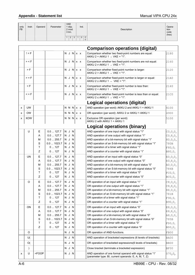
Appendix - Statement list Manual VIPA CPU 24x only FB
Instr.
Operand
Parameter
VKE 1 dep. 2 mod. 3 lim.
Ind.
Description
Opera-tion code (hex)
1 2 3 1 0 OV
A-6 HB99E - CPU - Rev. 08/32
Comparison operations (digital) ! = F N J N x x Comparison whether two fixed-point numbers are equal:
AKKU 2 = AKKU 1 → VKE = "1". 2180
> < F N J N x x Comparison whether two fixed-point numbers are not equal: AKKU 2 ≠ AKKU 1 → VKE = "1".
2160
> F N J N x x Comparison whether fixed-point number is larger: AKKU 2 > AKKU 1 → VKE = "1".
2120
> = F N J N x x Comparison whether fixed-point number is larger or equal: AKKU 2 ≥ AKKU 1 → VKE = "1".
21A0
< F N J N x x Comparison whether fixed-point number is less than: AKKU 2 < AKKU 1 → VKE = "1".
2140
< = F N J N x x Comparison whether fixed-point number is less than or equal: AKKU 2 ≤ AKKU 1 → VKE = "1".
21C0
Logical operations (digital) x UW N N N x x AND operation (per word): AKKU 2 and AKKU 1 = AKKU 1 4100
x OW N N N x x OR operation (per word): AKKU 2 or AKKU 1 AKKU 1 4900
x XOW N N N x x Exclusive OR operation (per word): AKKU 2 with AKKU 1 = AKKU 1
5100
Logical operations (binary) U E 0.0 ... 127.7 N J N AND operation of one input with signal status "1" C0i0y0y A 0.0 ... 127.7 N J N AND operation of one output with signal status “1” C0i8y0y M 0.0 ... 255.7 N J N AND operation of a bit-memory bit with signal status “1” 80i0y0a S
T 0.0 ... 1023.7
0 ... 127 N N
J J
N N
AND operation of an S-bit-memory bit with signal status “1” AND operation of a timer with signal status “1”
780B
F80t0t
Z 0 ... 127 N J N AND operation of a counter with signal status “1” B80z0z
UN E 0.0 ... 127.7 N J N AND operation of an input with signal status “0” E0i0y0y A 0.0 ... 127.7 N J N AND operation of one output with signal status “0” E0i8y0y M 0.0 ... 255.7 N J N AND operation of a bit-memory bit with signal status “0” A0i0y0y S
T 0.0 ... 1023.7
0 ... 127 N N
J J
N N
AND operation of an S-bit-memory bit with signal status “0” AND operation of a timer with signal status “0”
784B
FC0t0t
Z 0 ... 127 N J N AND operation of a counter with signal status “0” BC0z0z
O E 0.0 ... 127.7 N J N OR operation of an input with signal status “1” C8i0y0y A 0.0 ... 127.7 N J N OR operation of one output with signal status “1” C8i8y0y M 0.0 ... 255.7 N J N OR operation of a bit-memory bit with signal status “1” 88i0y0y S
T 0.0 ... 1023.7
0 ... 127 N N
J J
N N
OR operation of an S-bit-memory bit with signal status “1” OR operation of a timer with signal status “1”
781B
F90t0t
Z 0 ... 127 N J N OR operation of a counter with signal status “1” B90z0z
ON E 0.0 ... 127.7 N J N OR operation of an input with signal status “0” E8i0y0y A 0.0 ... 127.7 N J N OR operation of one output with signal status “0” E8i8y0y M 0.0 ... 255.7 N J N OR operation of a bit-memory bit with signal status “0” A8i0y0y S
T 0.0 ... 1023.7
0 ... 127 N N
J J
N N
OR operation of an S-bit-memory bit with signal status “0” OR operation of a timer with signal status “0”
785B
FD0t0t
Z 0 ... 127 N J N OR operation of a counter with signal status “0” BD0z0z
O N J N OR operation of AND-functions. FB00
U( N J N AND operation of bracketed expressions (6 levels of brackets) BA00
O( N J N OR operation of bracketed expressions(6 levels of brackets) BB00
) N J N Close bracket (terminate a bracketed expression) BF00
x U =FOOP N J N AND operation of one formal operand with signal status “1” (parameter type: BI, current operands: E, A, M, T, Z)
070p0p
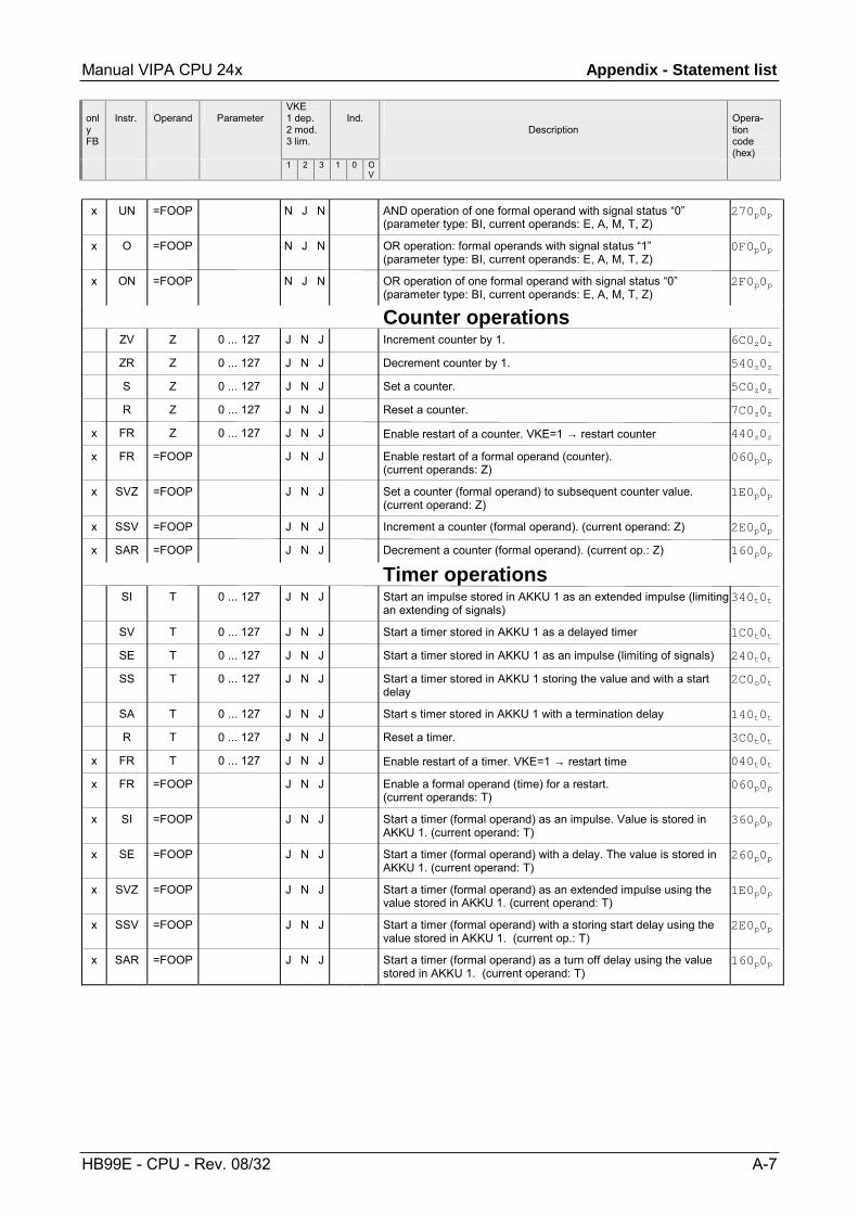
Manual VIPA CPU 24x Appendix - Statement list only FB
Instr.
Operand
Parameter
VKE 1 dep. 2 mod. 3 lim.
Ind.
Description
Opera-tion code (hex)
1 2 3 1 0 OV
HB99E - CPU - Rev. 08/32 A-7
x UN =FOOP N J N AND operation of one formal operand with signal status “0” (parameter type: BI, current operands: E, A, M, T, Z)
270p0p
x O =FOOP N J N OR operation: formal operands with signal status “1” (parameter type: BI, current operands: E, A, M, T, Z)
0F0p0p
x ON =FOOP N J N OR operation of one formal operand with signal status “0” (parameter type: BI, current operands: E, A, M, T, Z)
2F0p0p
Counter operations ZV Z 0 ... 127 J N J Increment counter by 1. 6C0z0z
ZR Z 0 ... 127 J N J Decrement counter by 1. 540z0z
S Z 0 ... 127 J N J Set a counter. 5C0z0z
R Z 0 ... 127 J N J Reset a counter. 7C0z0z
x FR Z 0 ... 127 J N J Enable restart of a counter. VKE=1 → restart counter 440z0z
x FR =FOOP J N J Enable restart of a formal operand (counter). (current operands: Z)
060p0p
x SVZ =FOOP J N J Set a counter (formal operand) to subsequent counter value. (current operand: Z)
1E0p0p
x SSV =FOOP J N J Increment a counter (formal operand). (current operand: Z) 2E0p0p
x SAR =FOOP J N J Decrement a counter (formal operand). (current op.: Z) 160p0p
Timer operations SI T 0 ... 127 J N J Start an impulse stored in AKKU 1 as an extended impulse (limiting
an extending of signals) 340t0t
SV T 0 ... 127 J N J Start a timer stored in AKKU 1 as a delayed timer 1C0t0t
SE T 0 ... 127 J N J Start a timer stored in AKKU 1 as an impulse (limiting of signals) 240t0t
SS T 0 ... 127 J N J Start a timer stored in AKKU 1 storing the value and with a start delay
2C0o0t
SA T 0 ... 127 J N J Start s timer stored in AKKU 1 with a termination delay 140t0t
R T 0 ... 127 J N J Reset a timer. 3C0t0t
x FR T 0 ... 127 J N J Enable restart of a timer. VKE=1 → restart time 040t0t
x FR =FOOP J N J Enable a formal operand (time) for a restart. (current operands: T)
060p0p
x SI =FOOP J N J Start a timer (formal operand) as an impulse. Value is stored in AKKU 1. (current operand: T)
360p0p
x SE =FOOP J N J Start a timer (formal operand) with a delay. The value is stored in AKKU 1. (current operand: T)
260p0p
x SVZ =FOOP J N J Start a timer (formal operand) as an extended impulse using the value stored in AKKU 1. (current operand: T)
1E0p0p
x SSV =FOOP J N J Start a timer (formal operand) with a storing start delay using the value stored in AKKU 1. (current op.: T)
2E0p0p
x SAR =FOOP J N J Start a timer (formal operand) as a turn off delay using the value stored in AKKU 1. (current operand: T)
160p0p
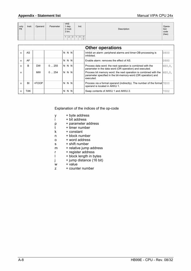
Appendix - Statement list Manual VIPA CPU 24x only FB
Instr.
Operand
Parameter
VKE 1 dep. 2 mod. 3 lim.
Ind.
Description
Opera-tion code (hex)
1 2 3 1 0 OV
A-8 HB99E - CPU - Rev. 08/32
Other operations x AS N N N Inhibit an alarm: peripheral alarms and timer-OB-processing is
inhibited. 0800
x AF N N N Enable alarm: removes the effect of AS. 0880
x B DW 0 ... 255 N N N Process data word: the next operation is combined with the parameter in the data word (OR operation) and executed.
6E0o0o
x MW 0 ... 254 N N N Process bit memory word: the next operation is combined with the parameter specified in the bit-memory-word (OR operation) and executed.
4E0o0o
x BI =FOOP N N N Process via a formal operand (indirectly). The number of the formal operand is located in AKKU 1.
7E00
x TAK N N N Swap contents of AKKU 1 and AKKU 2. 7002
Explanation of the indices of the op-code y + byte address i + bit address p + parameter address t + timer number k + constant n + block number o + word address s + shift number m + relative jump address r + register address l + block length in bytes j + jump distance (16 bit) w + value z + counter number
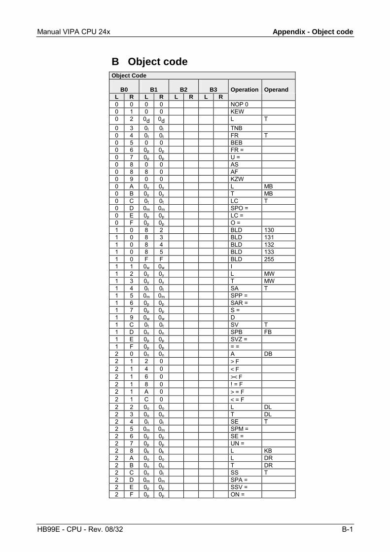
Manual VIPA CPU 24x Appendix - Object code
HB99E - CPU - Rev. 08/32 B-1
B Object code
Object Code
B0
B1
B2
B3 Operation
Operand
L R L R L R L R 0 0 0 0 NOP 0 0 1 0 0 KEW 0 2 0d 0d L T 0 3 0l 0l TNB 0 4 0t 0t FR T 0 5 0 0 BEB 0 6 0p 0p FR = 0 7 0p 0p U = 0 8 0 0 AS 0 8 8 0 AF 0 9 0 0 KZW 0 A 0y 0y L MB 0 B 0y 0y T MB 0 C 0t 0t LC T 0 D 0m 0m SPO = 0 E 0p 0p LC = 0 F 0p 0p O = 1 0 8 2 BLD 130 1 0 8 3 BLD 131 1 0 8 4 BLD 132 1 0 8 5 BLD 133 1 0 F F BLD 255 1 1 0w 0w I 1 2 0y 0y L MW 1 3 0y 0y T MW 1 4 0t 0t SA T 1 5 0m 0m SPP = 1 6 0p 0p SAR = 1 7 0p 0p S = 1 9 0w 0w D 1 C 0t 0t SV T 1 D 0n 0n SPB FB 1 E 0p 0p SVZ = 1 F 0p 0p = = 2 0 0n 0n A DB 2 1 2 0 > F 2 1 4 0 < F 2 1 6 0 >< F 2 1 8 0 ! = F 2 1 A 0 > = F 2 1 C 0 < = F 2 2 0o 0o L DL 2 3 0o 0o T DL 2 4 0t 0t SE T 2 5 0m 0m SPM = 2 6 0p 0p SE = 2 7 0p 0p UN = 2 8 0k 0k L KB 2 A 0o 0o L DR 2 B 0o 0o T DR 2 C 0o 0t SS T 2 D 0m 0m SPA = 2 E 0p 0p SSV = 2 F 0p 0p ON =

Appendix - Object code Manual VIPA CPU 24x
B-2 HB99E - CPU - Rev. 08/32
Object Code
B0
B1
B2
B3 Operation
Operand
L R L R L R L R 3 0 0 1 0k 0k 0k 0k L KZ 3 0 0 2 0k 0k 0k 0k L KT 3 0 0 4 0k 0k 0k 0k L KF 3 0 1 0 0k 0k 0k 0k L KC 3 0 2 0 0k 0k 0k 0k L KY 3 0 4 0 0k 0k 0k 0k L KH 3 0 8 0 0k 0k 0k 0k L KM 3 2 0o 0o L DW 3 3 0o 0o T DW 3 4 0t 0t SI T 3 5 0m 0m SPN = 3 6 0p 0p SI = 3 7 0p 0p RB = 3 C 0t 0t R T 3 D 0n 0n SPA FB 3 E 0p 0p RD = 3 F 0p 0p LW = 4 0 0 0r LIR 4 1 0 0 UW 4 2 0z 0z L Z 4 4 0z 0z FR Z 4 5 0m 0m SPZ = 4 6 0p 0p L = 4 8 0 0r TIR 4 9 0 0 OW 4 A 0y 0y L EB 4 A 8y 0y L AB 4 B 0y 0y T EB 4 B 8y 0y T AB 4 C 0z 0z LC Z 4 D 0n 0n SPB OB 4 E 0o 0o B MW 5 0 0k 0k ADD BF 5 1 0 0 XOW 5 2 0y 0y L EW 5 2 8y 0y L AW 5 3 0y 0y T EW 5 3 8y 0y T AW 5 4 0z 0z ZR Z 5 5 0n 0n SPB PB 5 8 0 0 0k 0k 0k 0k ADD KF 5 9 0 0 -F 5 C 0z 0z S Z 5 D 0n 0n SPB SB 6 1 0s 0s SLW 6 2 0o 0o L BS 6 3 0o 0o T BS 6 5 0 0 BE 6 5 0 1 BEA 6 6 0p 0p T = 6 8 0 B LDI A1 6 8 0 F TDI A1 6 8 2 B LDI A2 6 8 2 F TDI A2 6 9 0s 0s SRW 6 C 0z 0z ZV Z 6 D 0n 0n SPA OB 6 E 0o 0o B DW
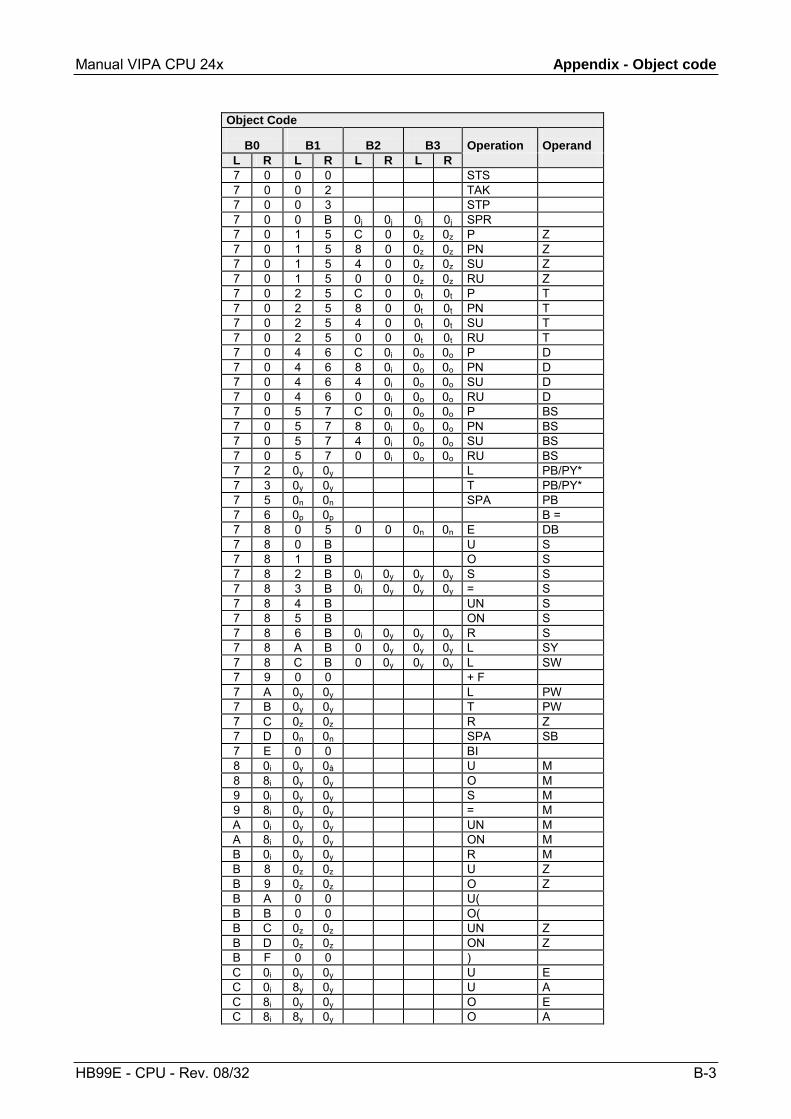
Manual VIPA CPU 24x Appendix - Object code
HB99E - CPU - Rev. 08/32 B-3
Object Code
B0
B1
B2
B3 Operation
Operand
L R L R L R L R 7 0 0 0 STS 7 0 0 2 TAK 7 0 0 3 STP 7 0 0 B 0j 0j 0j 0j SPR 7 0 1 5 C 0 0z 0z P Z 7 0 1 5 8 0 0z 0z PN Z 7 0 1 5 4 0 0z 0z SU Z 7 0 1 5 0 0 0z 0z RU Z 7 0 2 5 C 0 0t 0t P T 7 0 2 5 8 0 0t 0t PN T 7 0 2 5 4 0 0t 0t SU T 7 0 2 5 0 0 0t 0t RU T 7 0 4 6 C 0i 0o 0o P D 7 0 4 6 8 0i 0o 0o PN D 7 0 4 6 4 0i 0o 0o SU D 7 0 4 6 0 0i 0o 0o RU D 7 0 5 7 C 0i 0o 0o P BS 7 0 5 7 8 0i 0o 0o PN BS 7 0 5 7 4 0i 0o 0o SU BS 7 0 5 7 0 0i 0o 0o RU BS 7 2 0y 0y L PB/PY* 7 3 0y 0y T PB/PY* 7 5 0n 0n SPA PB 7 6 0p 0p B = 7 8 0 5 0 0 0n 0n E DB 7 8 0 B U S 7 8 1 B O S 7 8 2 B 0i 0y 0y 0y S S 7 8 3 B 0i 0y 0y 0y = S 7 8 4 B UN S 7 8 5 B ON S 7 8 6 B 0i 0y 0y 0y R S 7 8 A B 0 0y 0y 0y L SY 7 8 C B 0 0y 0y 0y L SW 7 9 0 0 + F 7 A 0y 0y L PW 7 B 0y 0y T PW 7 C 0z 0z R Z 7 D 0n 0n SPA SB 7 E 0 0 BI 8 0i 0y 0â U M 8 8i 0y 0y O M 9 0i 0y 0y S M 9 8i 0y 0y = M A 0i 0y 0y UN M A 8i 0y 0y ON M B 0i 0y 0y R M B 8 0z 0z U Z B 9 0z 0z O Z B A 0 0 U( B B 0 0 O( B C 0z 0z UN Z B D 0z 0z ON Z B F 0 0 ) C 0i 0y 0y U E C 0i 8y 0y U A C 8i 0y 0y O E C 8i 8y 0y O A
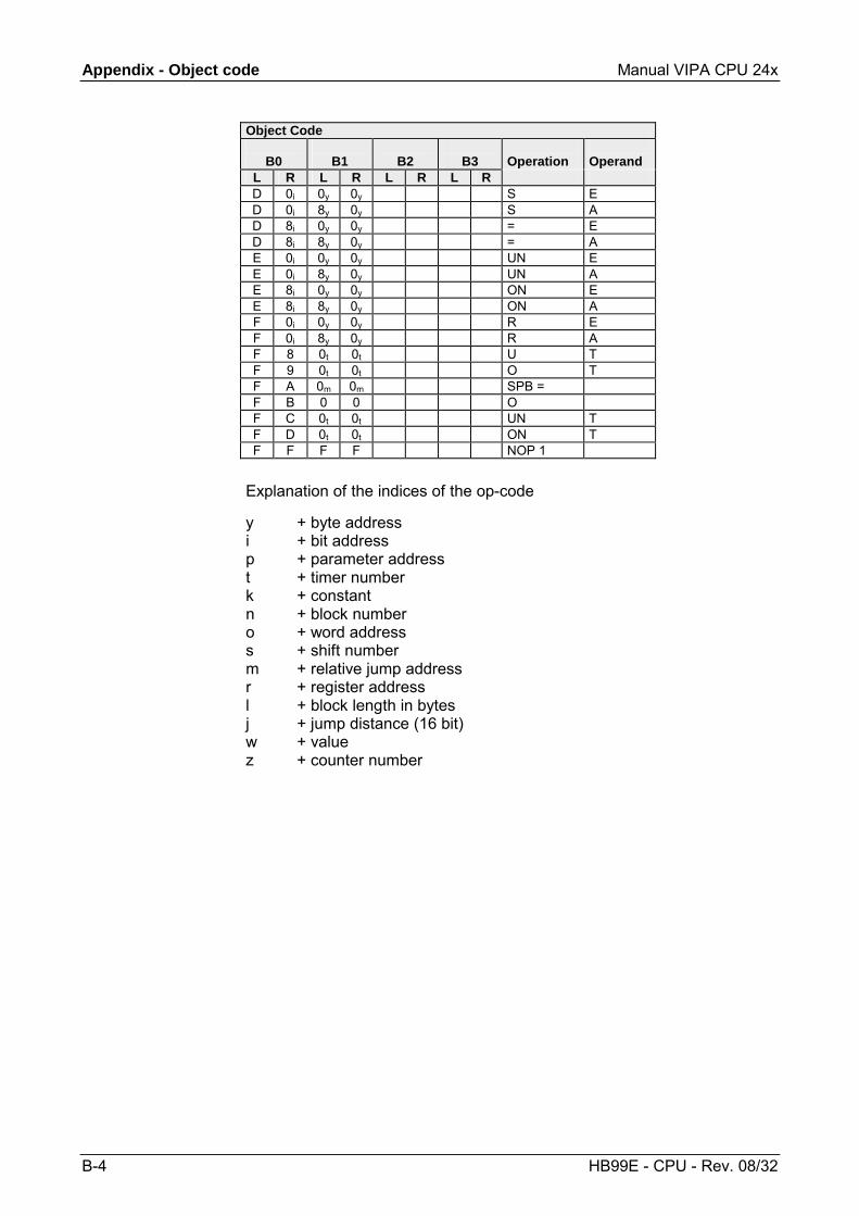
Appendix - Object code Manual VIPA CPU 24x
B-4 HB99E - CPU - Rev. 08/32
Object Code
B0
B1
B2
B3 Operation
Operand
L R L R L R L R D 0i 0y 0y S E D 0i 8y 0y S A D 8i 0y 0y = E D 8i 8y 0y = A E 0i 0y 0y UN E E 0i 8y 0y UN A E 8i 0y 0y ON E E 8i 8y 0y ON A F 0i 0y 0y R E F 0i 8y 0y R A F 8 0t 0t U T F 9 0t 0t O T F A 0m 0m SPB = F B 0 0 O F C 0t 0t UN T F D 0t 0t ON T F F F F NOP 1
Explanation of the indices of the op-code y + byte address i + bit address p + parameter address t + timer number k + constant n + block number o + word address s + shift number m + relative jump address r + register address l + block length in bytes j + jump distance (16 bit) w + value z + counter number

Manual VIPA CPU 24x Appendix - Index
HB99E - CPU - Rev. 08/32 C-1
C Index
1 15pin PG/OP D-type socket ....... 2-10
2 20mA interface ........................... 2-11
A Addressing by means of DB1 ....... 3-5 Alarm .......................................... 12-1
Diagnostic data..................... 12-11 Interrupt .........................12-2, 12-8 Outline .................................... 12-2 Priority and response time...... 12-7 Processing.....................7-14, 8-27 Prompt .................................... 12-9
Analog data processing .............. 10-9 Example................................ 10-14
A-NR ......................................... 10-19 ANZ 0.......................................... 9-76 ANZ 1.......................................... 9-76 ANZW ....................................... 10-19 ANZW Indicator word ......5-36, 10-27
Status ................................... 10-34 Application layer ........................... 4-5 Applications .................................. 1-4 Applications for I/O modules......... 3-2
B Bit communication layer ............... 4-4 BLGR ........................................ 10-20 Block size.................................. 10-37 Blockgröße.................................. 5-15 Blocks ........................................... 8-9
handler blocks ...................... 10-17 integrated blocks .................... 10-1 processing .............................. 8-32 Types........................................ 8-9
C Clock........................................... 11-2
Battery backup........................ 11-2 Configuration .......................... 11-3 Correction value ..................... 11-6 Data area................................ 11-7 Functions ................................ 11-1 Initialisation............................. 11-4 Read time / date ................... 11-12 set/read................................. 11-12 Status word........................... 11-10
Commissioning ........................... 2-17 Communication layers .................. 4-2 Components ................................. 2-8 Compression............................... 8-33 Control bit abbreviations............. 2-29 Counter operations ..................... 9-23
CPU 24x Block diagram......................... 2-16 Booting behavior .................... 2-18 FBs, OBs, special instructions 2-34 LEDs......................................... 2-8 Memory areas ........................ 2-25 Operands.................................. 1-8 Operation.................................. 1-7 Pin assignment....................... 2-10 Properties ................................. 2-5 Saving a program internally ... 2-20 Supply voltage.......................... 2-9 Technical data ........................ 2-36
CPU 24x DP ................................. 2-4 Address selector .................... 2-15 Addressing ............................... 6-9 Bus terminator ........................ 6-26 Cabling ................................... 6-25 Commissioning....................... 6-24 Communication protocol .......... 6-3 Data consistency...................... 6-5 Datenverkehr............................ 6-3 Diagnostic
LEDs .................................. 6-27 Diagnostics............................. 6-14
equipment related.............. 6-16 standard............................. 6-15
Example ................................. 6-28 Ident-number ............................ 6-8 Initialization phase.................. 6-26 Installation guidelines............. 6-19 LEDs....................................... 2-14 Network examples.................. 6-22 Parameter data....................... 6-12 Status messages.................... 6-17 Technical data ........................ 2-38 Termination of lines................ 6-24
CPU 24x-2BT01 ........................... 2-3 Address
Broadcast- ......................... 5-10 Ethernet/IP-........................ 5-10
Adresse Initial address..................... 5-11
ANZW Indicator word ............. 5-36 Applications .............................. 5-6 Boot ........................................ 5-29 Communications ...................... 5-3 Configuration .......................... 5-12
Example............................. 5-16 Error indicator......................... 5-36 Ethernet interface................... 2-13 LEDs....................................... 2-12 Links ....................................... 5-32 Network planning ..................... 5-7 NETZEIN (Power on) ............. 5-15 ORG-Format........................... 5-32 PAFE Param.fehler ................ 5-43
Appendix - Index Manual VIPA CPU 24x
C-2 HB99E - CPU - Rev. 08/32
PLC header ............................ 5-34 PLC-Programming.................. 5-14 Synchronization ...................... 5-15 System properties ................... 5-30 Technical data ........................ 2-37 TRADA ................................... 5-35 Wildcard length....................... 5-35
CPU 24x-2BT10 ........................... 2-3 Address
First start-up....................... 4-10 IP 4-10
Communication....................... 4-14 Connections ....................... 4-14 Programming ..................... 4-16 Types ................................. 4-14
Coupling ................................. 4-27 Error
Diagnostic .......................... 4-30 Messages........................... 4-26
Ethernet interface ................... 2-13 Function overview................... 4-15 IP address
IP classes........................... 4-11 LEDs....................................... 2-12 NCM diagnostic ...................... 4-30 ORG format ............................ 4-27 other systems ......................... 4-27 PLC header ............................ 4-29 PLC user program .................. 4-23 Protocols................................... 4-7 RFC1006 .................................. 4-9 Subnet-Mask .......................... 4-10 Technical data ........................ 2-37
D Data block
DB 1...................................... 10-61 Data blocks................................. 8-20 DBNR........................................ 10-19
E Error
CPU 24x Prompt error..................... 12-10 Reaction-OBs..................... 8-29 Troubleshooting the prog... 8-35 USTACK ............................ 2-27
ERW identifier............................. 4-27 Ethernet
Address .................................. 5-10 Standards ................................. 5-9
F Features........................................ 1-5 Function block............................. 8-15
FB 238 COMPR...................... 10-3 FB 239 DELETE..................... 10-4 FB 241 COD.16 ...................... 10-6 FB 242 Multiplier..................... 10-7 FB 243 Divider........................ 10-8 FB 244 SEND ....................... 10-38
FB 245 RECEIVE................. 10-41 FB 246 FETCH..................... 10-44 FB 247 CONTROL ............... 10-45 FB 248 RESET..................... 10-46 FB 249 SYNCHRON ............ 10-47 FB 250 RLG AE ..................... 10-9
function selector ........................... 2-8 FUP Function plan........................ 8-5
G GSD-Datei .................................... 6-8
H H1................................................. 5-4 Handler blocks.......................... 10-17
Block size ............................. 10-37 Error indicator ANZW ........... 10-27 FBs ....................................... 10-38 Length word.......................... 10-35 Parameter
indirect ............................. 10-24 Parameters........................... 10-18 QTYP/ZTYP ......................... 10-25
Hardware description ................... 2-1 Host-ID ....................................... 4-11 Hub ........................................ 4-6, 5-2
I Ident-number ................................ 6-8 Industrial Ethernet ........................ 5-4 Integrated
Data block DB 1 ................... 10-61 FBs ......................................... 10-2 Special-OBs ......................... 10-48
IP-Address.................................. 5-10 ISO/OSI reference model ............. 4-3
K KOP ladder diagram..................... 8-5
L Length word.............................. 10-35
M Memory
Compession ........................... 8-33 Memory Module.......................... 2-24
N NCM diagnostic .......................... 4-30 Network ................................. 4-6, 5-2
Layer ........................................ 4-4 Numeric representation .............. 8-34
O ON/OFF switch............................. 2-9 Operand areas ............................. 8-6 operating modes........................... 2-8

Manual VIPA CPU 24x Appendix - Index
HB99E - CPU - Rev. 08/32 C-3
Operating modes ...................7-1, 7-2 Start-Up .................................... 7-8 STOP........................................ 7-6
ORG format ................................ 4-27 ORG Organization format........... 5-32 Organization block.............8-13, 8-25
OB 1 ..............................7-12, 8-25 OB 10 to 13 ............................ 12-4 OB 160 ................................. 10-50 OB 19 ..................................... 8-29 OB 21 ..................................... 7-10 OB 22 ..................................... 7-10 OB 23 ..................................... 8-29 OB 24 ..................................... 8-29 OB 251 ................................. 10-51 OB 27 ..................................... 8-30 OB 31 ................................... 10-49 OB 32 ..................................... 8-30 OB 33 ..................................... 8-30 OB 34 ..................................... 8-31 OB 6 ..............................8-27, 12-6
OV Overflow ............................... 9-76 OVERALL RESET ...................... 2-19
P PAFE ...............................5-43, 10-20 Peripheral modules
Addressing................................ 3-3 Configuration ............................ 3-6
PLC Header.................................... 4-29
PLC header................................. 5-34 Presentation layer......................... 4-5 Primary operations ....................... 9-3 Principles ...................................... 1-1 Profibus DP master
Connectors ............................. 6-20 De-isolating lengths ................ 6-21 Line termination ...................... 6-21
Program block............................. 8-15 Program execution ..................... 8-22
cyclic ..............................7-12, 8-25 elapsed-time controlled .......... 12-6 timer controlled ..............8-25, 12-4
Program processing Levels ....................................... 7-3 time controlled ........................ 7-14 time-dependent....................... 7-15
Program structure......................... 8-8 Prompt ........................................ 12-9 Prompt error.............................. 12-10
Q QANF/ZANF ............................. 10-20 QLAE/ZLAE .............................. 10-20 QTYP/ZTYP.............................. 10-19 QTYP/ZTYP - Parameter.......... 10-25
R Reboot .................................2-19, 7-9
RECV1 (FB 235) ........................ 4-25 RFC1006 ...................................... 4-9
S Security layer................................ 4-4 selector switch.............................. 2-8 SEND1 (FB 234) ........................ 4-25 Sequence block.......................... 8-15 Session layer ................................ 4-5 Setting of flags ANZ, OV ............ 9-76 Special-OBs ............................. 10-48 SSNR........................................ 10-19 Star topology .............................. 2-13 Start-up
Interrupt .................................. 7-10 User interfaces ....................... 7-10
Start-Up ........................................ 7-8 STATUS ..................................... 2-22
Indicator................................ 10-27 VAR ........................................ 2-23
STEUERN Steuern VAR .......................... 5-27 VAR ........................................ 2-23
STEUERN (control) .................... 2-23 STL Statement list ........................ 8-4 STOP............................................ 7-6 Structure of the blocks................ 8-12 Supplementary operations ......... 9-40 Switch ........................................... 4-6 Synchronization of interfaces ..... 5-21 System.......................................... 2-2
Data........................................ 2-26 Operations.............................. 9-66 Overview .................................. 2-2
T TCP/IP................................... 4-7, 5-5
Test program.......................... 5-44 Timer operations ........................ 9-13 TRADA ....................................... 5-35 Transport layer ............................. 4-4 Triggering error........................... 7-16 Twisted pair .................................. 5-2 Twisted Pair.................................. 4-6
Restrictions............................... 5-8 Types of operation........................ 8-6
U UDP.............................................. 4-9 USTACK..................................... 2-27
V Versions........................................ 1-6
W Warm restart................................. 7-9 Wildcard length........................... 5-35

Appendix - Index Manual VIPA CPU 24x
C-4 HB99E - CPU - Rev. 08/32
M.Stich
![Company Profiles Vipa / Vipa Polimeri Page 1/18 profile Vipa... · Company Profiles Vipa / Vipa Polimeri Page 2/18 VIPA S.r.l. [beginnings]Vipa is a leading company in the field of](https://img.dokumen.tips/doc/110x75/5f5cfa7c6cc46b644e27ef7b/company-profiles-vipa-vipa-polimeri-page-118-profile-vipa-company-profiles.jpg)