Embed Size (px)
DESCRIPTION
cross over
Citation preview

� � � � � � � � � � � �
Owner’s Manual
WWW.BODYSOLID.COM
PCCO90XCABLE CROSSOVER
2
DO NOT REMOVE WARNING LABELS FROM
MANUAL OR MACHINE
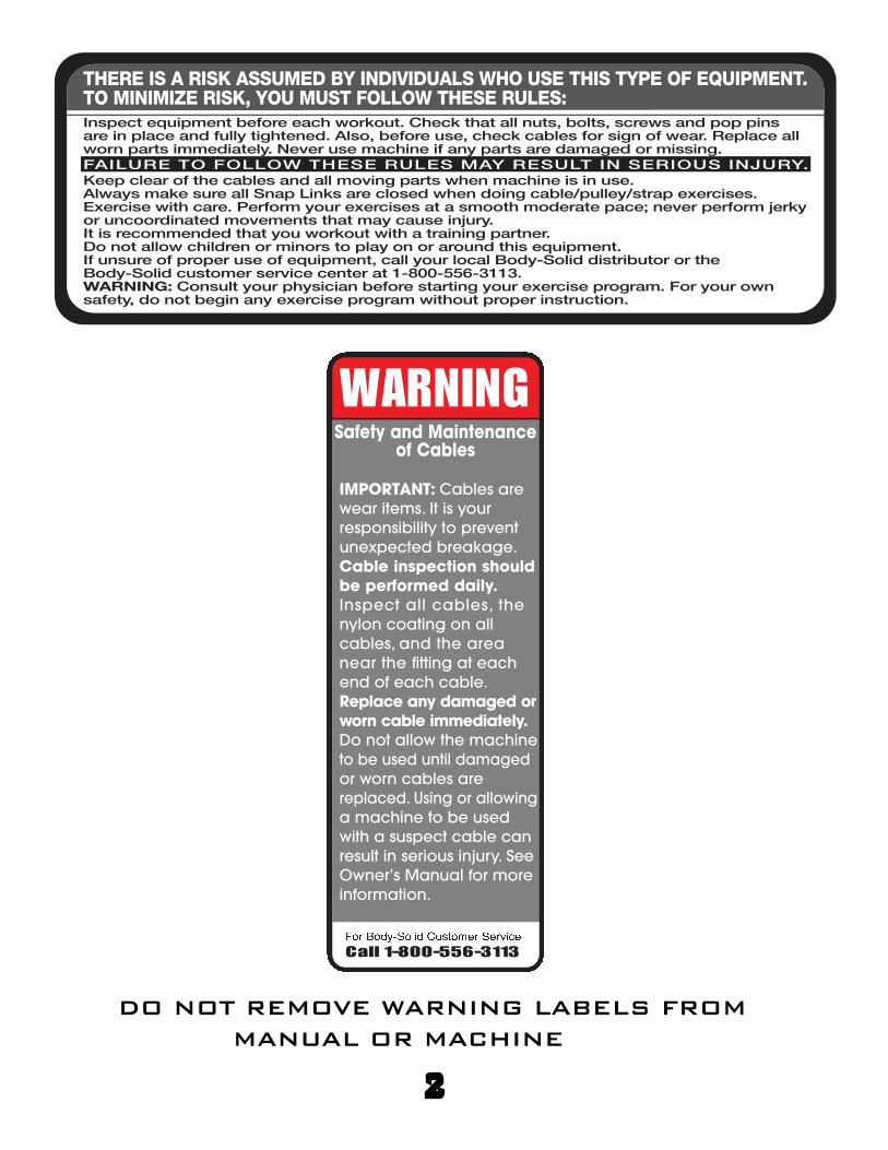
WARNINGSafety and Maintenance
of Cables
IMPORTANT: Cables are
wear items. It is your
responsibility to prevent
unexpected breakage.
Cable inspection shouldbe performed daily.Inspect all cables, the
nylon coating on all
cables, and the area
near the fitting at each
end of each cable.
Replace any damaged orworn cable immediately.Do not allow the machine
to be used until damaged
or worn cables are
replaced. Using or allowing
a machine to be used
with a suspect cable can
result in serious injury. See
Owner’s Manual for more
information.� � � � � � � � � � � � � � � � � � � � � � � � �Call 1-800-556-3113
THERE IS A RISK ASSUMED BY INDIVIDUALS WHO USE THIS TYPE OF EQUIPMENT.TO MINIMIZE RISK, YOU MUST FOLLOW THESE RULES:
Inspect equipment before each workout. Check that all nuts, bolts, screws and pop pins are in place and fully tightened. Also, before use, check cables for sign of wear. Replace all worn parts immediately. Never use machine if any parts are damaged or missing.
FAILURE TO FOLLOW THESE RULES MAY RESULT IN SERIOUS INJURY.
Keep clear of the cables and all moving parts when machine is in use.Always make sure all Snap Links are closed when doing cable/pulley/strap exercises.Exercise with care. Perform your exercises at a smooth moderate pace; never perform jerky or uncoordinated movements that may cause injury.It is recommended that you workout with a training partner.Do not allow children or minors to play on or around this equipment.If unsure of proper use of equipment, call your local Body-Solid distributor or the Body-Solid customer service center at 1-800-556-3113.WARNING: Consult your physician before starting your exercise program. For your own safety, do not begin any exercise program without proper instruction.
3
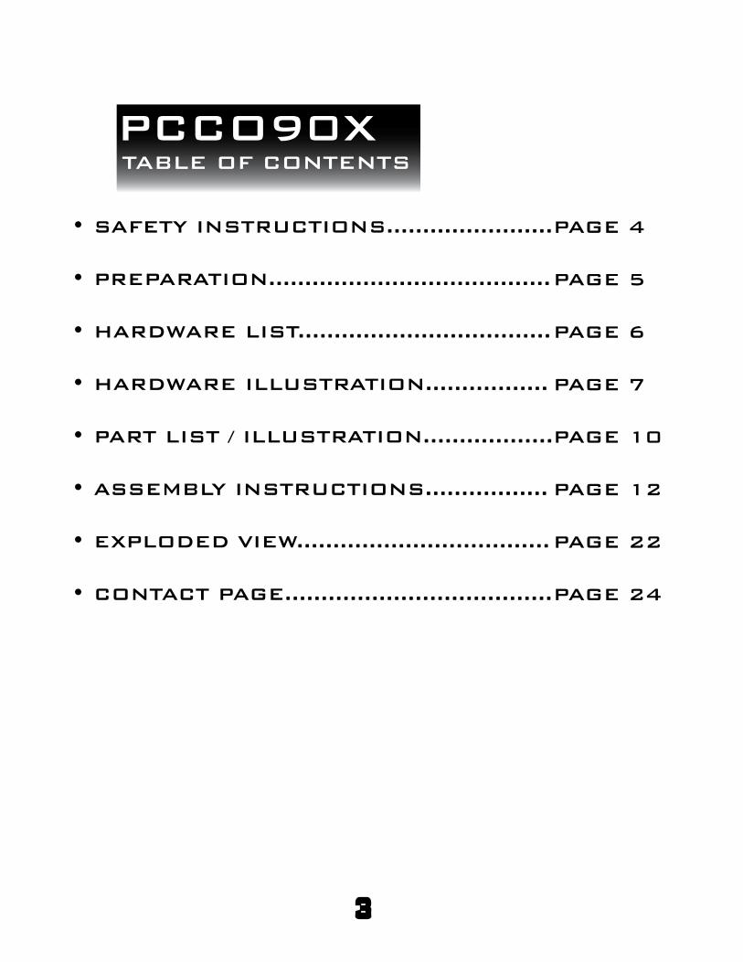
PCCO90XTABLE OF CONTENTS
SAFETY INSTRUCTIONS.......................
PREPARATION.......................................
HARDWARE LIST...................................
HARDWARE ILLUSTRATION.................
PART LIST / ILLUSTRATION..................
ASSEMBLY INSTRUCTIONS.................
EXPLODED VIEW...................................
CONTACT PAGE.....................................
•
•
•
•
•
•
•
•
PAGE 4
PAGE 5
PAGE 6
PAGE 7
PAGE 10
PAGE 12
PAGE 22
PAGE 24

4
PCCO90XSAFETY INSTRUCTIONS
When using exercise equipment,
you should always take basic
precautions including the
following:
Read all instructions before using the PCCO90X.
These instructions are written to ensure your safety
and to protect the unit.� � � � ! " # � $ " % � & ' % ( " & ) % * " ) ' ( ! � # + "# % , + - � " .Do not allow children on or near the equipment.
Use the equipment only for its intended purpose
as described in this guide. Do not use accessory
attachments that are not recommended by the
manufacturer. Such attachments might cause serious
injuries.
Wear proper excercise clothing and shoes for your
workout, no loose clothing.
Keep hands, limbs, loose clothing, and long hair well
out of the way of all moving parts
Use care when getting on or off the unit.
Do no overexert yourself or work to exhaustion.
If you feel any pain or abnormal symptoms, stop your
workout immediately and consult your physician.
Never operate unit when it has been dropped or
damaged. Return the equipment to a service center
for examination and repair.
Never drop or insert objects into any opening in the
equipment.
Always check the unit and its cables before each use.
Make sure that all fasteners and cables are secure
and in good working condition.
Do not use the equipment outdoors or near water.
•/•
•
•
•
•
•
•
•
•
•
•
Personal Safety During Assembly
Before beginning assembly, please take the time to
read the instructions thoroughly.
Read each step in the assembly instructions and
follow the steps in sequence. Do not skip ahead. If
you skip ahead, you may learn later that you have
to disassemble components and that you may have
damaged the equipment
Assemble and operate the PCCO90X on a solid, level
surface. Locate the unit a few feet from the walls or
furniture to provide easy access.
•
•
•
The PCCO90X is designed for your enjoyment. By
following these precautions and using common sense,
you will have many safe and pleasurable hours of
healthful exercise with your Powerline Cable
Crossover Machine.
After assembly, you should check all functions to
ensure correct operation. If you experience problems,
fi rst recheck the assembly instructions to locate any
possible errors made during assembly. If you are un-
able to correct the problem, call the dealer from whom
you purchased the machine or call 1-800-556-3113 for
the dealer nearest you.
Obtaining Service
Please use this Owner’s Manual to make sure that
all parts have been included in your shipment. When
ordering parts, you must use the part number and
description from this Owner’s Manual. Use only
Powerline by Body Solid replacement parts when
servicing this machine. Failure to do so will void your
warranty and could result in personal injury.
For information about product operation or
service, check out the offi cial Powerline website
at www.bodysolid.com or contact an authorized
Powerline dealer or a Powerline factory-authorized
service company or contact Body-Solid customer
service at one of the following:
Toll Free: 1-800-556-3113
Phone: 1-708-427-3555
Fax: 1-708-427-3556
Email: [email protected]
Or write to: Body-Solid, Inc.
Service Department
1900 S. Des Plaines Ave.
Forest Park, IL 60130 USA
Retain this Owner’s Manual for
furture reference. Part numbers
are required when ordering parts.

PCCO90XPREPARATION
Required tools
The basic tools that you must obtain before assembling
the PCCO90X include but are not limit to:
• Standard Wrench Set
• Metric Wrench Set
• Adjustable Wrench
• Standard / Metric Allen Key Set
Installation Requirements
Follow these installation requirements when assembling
the PCCO90X:
Set up the PCCO90X on a solid, fl at surface. A smooth,
fl at surface under the machine helps keep it level.
Provide ample space around the machine. Open space
around the machine allows for easier access.
For aesthetic purposes, insert all bolts in the same
direction unless specifi ed (in text or illustrations) to do
otherwise.
Leave room for adjustments. Tighten fasteners such as
bolts, nuts, and screws so the unit is stable, but leave
room for adjustments. Do not fully tighten fasteners until
instructed in the assembly steps to do so.
Fill out and mail the warranty card.
Ordering Replacement Parts
If you need to order replacement parts please be
prepared to provide the following information
when contacting us so that we can assist you better.
1. Model Number
2. Place of Purchase
3. Serial Number (S/N)
4. Part # and Description
Assembly Tips
Read all “Notes” on each page before beginning each step.
While you may be able to assemble the PCCO90X using the
illustrations only, important safety notes and other tips may be
included in the text.
Some pieces may have extra holes that you will not use. Use
only those holes indicated in the instructions and illustrations.
NOTE: With so many assembled parts, proper
alignment and adjustment is critical. While
tightening the nuts and bolts, be sure to leave
room for adjustments.
NOTE: The bottles that are marked “Poison” is your
touch up paint. Keep away from children.0 1 2 3 4 5 6: Obtain assistance! If you feel like you can’t
assemble the PCCO90X by yourself then do
not attempt to do so as this could result in
injury. Review the Installation Requirements
before proceeding with the following steps.
5
YOUR S/N # CAN
BE FOUND HERE
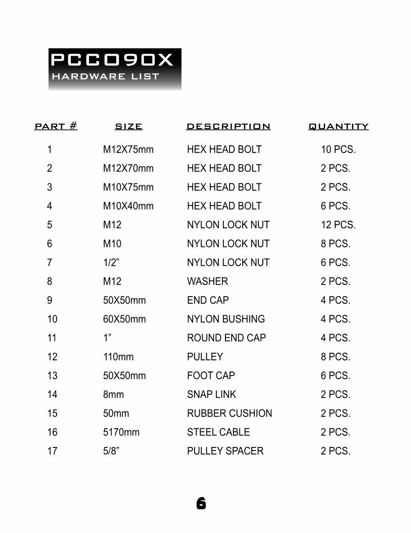
PCCO90XHARDWARE LIST
QUANTITYDESCRIPTIONSIZEPART #
6
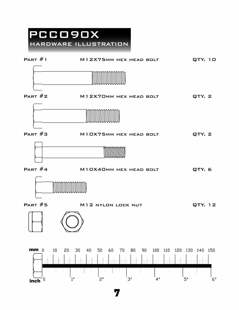
PCCO90XHARDWARE ILLUSTRATION
7
Part #3 M10X75mm hex head bolt QTY. 2
Part #2 M12X70mm hex head bolt QTY. 2
Part #1 M12X75mm hex head bolt QTY. 10
Part #4 M10X40mm hex head bolt QTY. 6
Part #5 M12 nylon lock nut QTY. 12
8
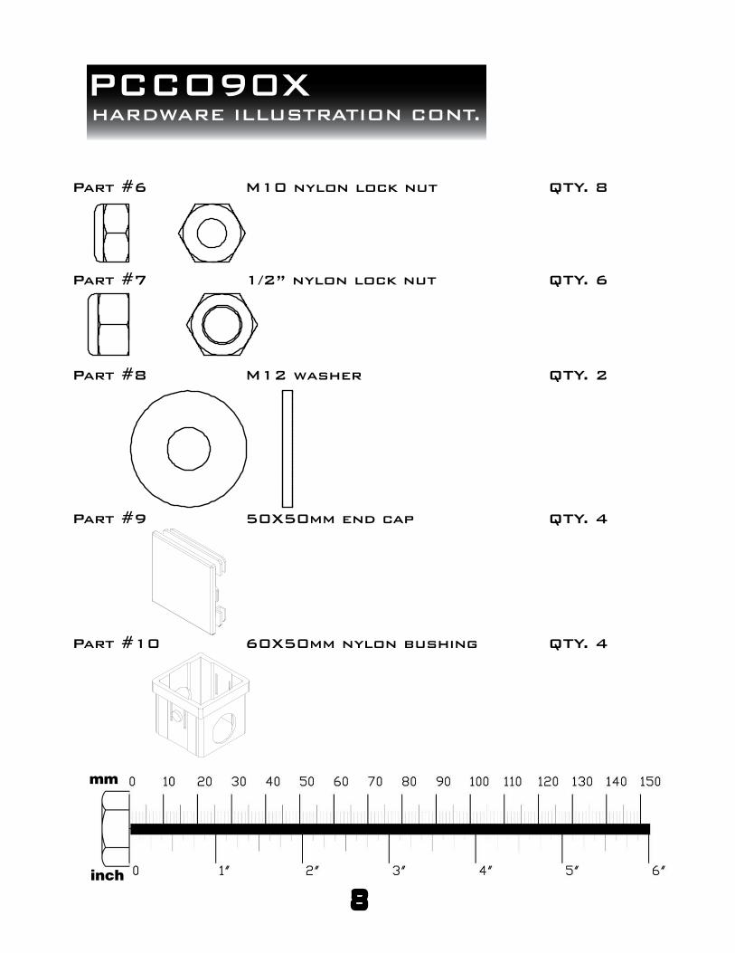
PCCO90XHARDWARE ILLUSTRATION CONT.
Part #7 1/2” nylon lock nut QTY. 6
Part #8 M12 washer QTY. 2
Part #9 50X50mm end cap QTY. 4
Part #6 M10 nylon lock nut QTY. 8
Part #10 60X50mm nylon bushing QTY. 4

9
PCCO90XHARDWARE ILLUSTRATION CONT.
Part #12 110mm pulley QTY. 8
Part #13 50X50mm foot cap QTY. 6
Part #14 8mm snap link QTY. 2
Part #11 1” round end cap QTY. 4
Part #15 50mm rubber cushion QTY. 2
Part #17 5/8” pulley spacer QTY. 2
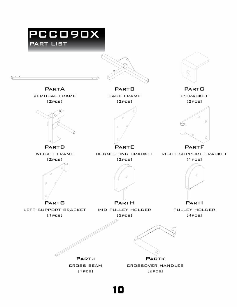
PCCO90XPART LIST
10
PartBbase frame
[2pcs]
PartCl-bracket
[2pcs]
PartAvertical frame
[2pcs]
PartEconnecting bracket
[2pcs]
PartFright support bracket
[1pcs]
PartDweight frame
[2pcs]
PartHmid pulley holder
[2pcs]
PartIpulley holder
[4pcs]
PartGleft support bracket
[1pcs]
Partjcross beam
[1pcs]
Partkcrossover handles
[2pcs]

11
PCCO90XNOTES

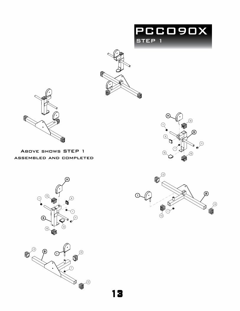
PCCO90XSTEP 1
BE CAREFUL TO ASSEMBLE ALL COMPONENTS
IN THE SEQUENCE THAT THEY ARE PRESENTED.
NOTE:
finger tighten all hardware first in this step. wrench tighten at the
end of this step. some components may be PRE-ASSEMBLED.
nylon lock nuts will not fully screw onto bolts, must wrench tighten.
1A. insert a foot cap onto each end of both base
frames (B) using a total of
6 - (#13) 50X50mm foot cap
1B. attach a pulley holder (I) to each base frame (B)
using a total of:
2 - (#7) 1/2” nylon lock nut
1C. insert a nylon bushing into the top and bottom
openings of both weight frames (D) using a total of:
4 - (#10) 60X50mm nylon bushing
1D. insert a end cap into the front openings of both
weight frames (D) using a total of
2 - (#9) 50X50mm end cap
1E. insert a round end cap into the left and right
openings of both weight frames (D) using a total of:
4 - (#11) 1” round end cap
1F. insert rubber cushion onto the lower lip of both
weight frames (D) using a total of:
2 - (#15) 50mm rubber cushion
1G. attach a mid pulley holder (H) to each weight
frame (D) using a total of:
2 - (#7) 1/2” nylon lock nut
12
PCCO90XSTEP 1
13
Above shows STEP 1
assembled and completed
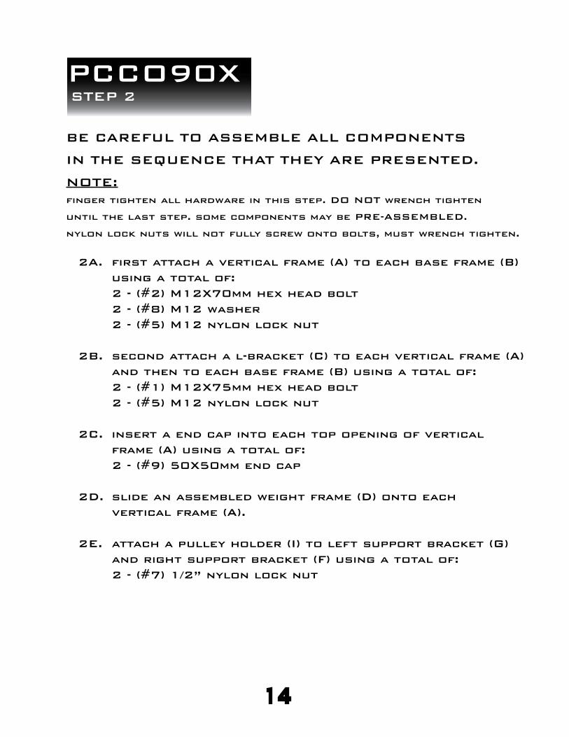
PCCO90XSTEP 2
BE CAREFUL TO ASSEMBLE ALL COMPONENTS
IN THE SEQUENCE THAT THEY ARE PRESENTED.
NOTE:
finger tighten all hardware in this step. DO NOT wrench tighten
until the last step. some components may be PRE-ASSEMBLED.
nylon lock nuts will not fully screw onto bolts, must wrench tighten.
2A. first attach a vertical frame (A) to each base frame (B)
using a total of:
2 - (#2) M12X70mm hex head bolt
2 - (#8) M12 washer
2 - (#5) M12 nylon lock nut
2B. second attach a l-bracket (C) to each vertical frame (A)
and then to each base frame (B) using a total of:
2 - (#1) M12X75mm hex head bolt
2 - (#5) M12 nylon lock nut
2C. insert a end cap into each top opening of vertical
frame (A) using a total of:
2 - (#9) 50X50mm end cap
2D. slide an assembled weight frame (D) onto each
vertical frame (A).
2E. attach a pulley holder (I) to left support bracket (G)
and right support bracket (F) using a total of:
2 - (#7) 1/2” nylon lock nut
14
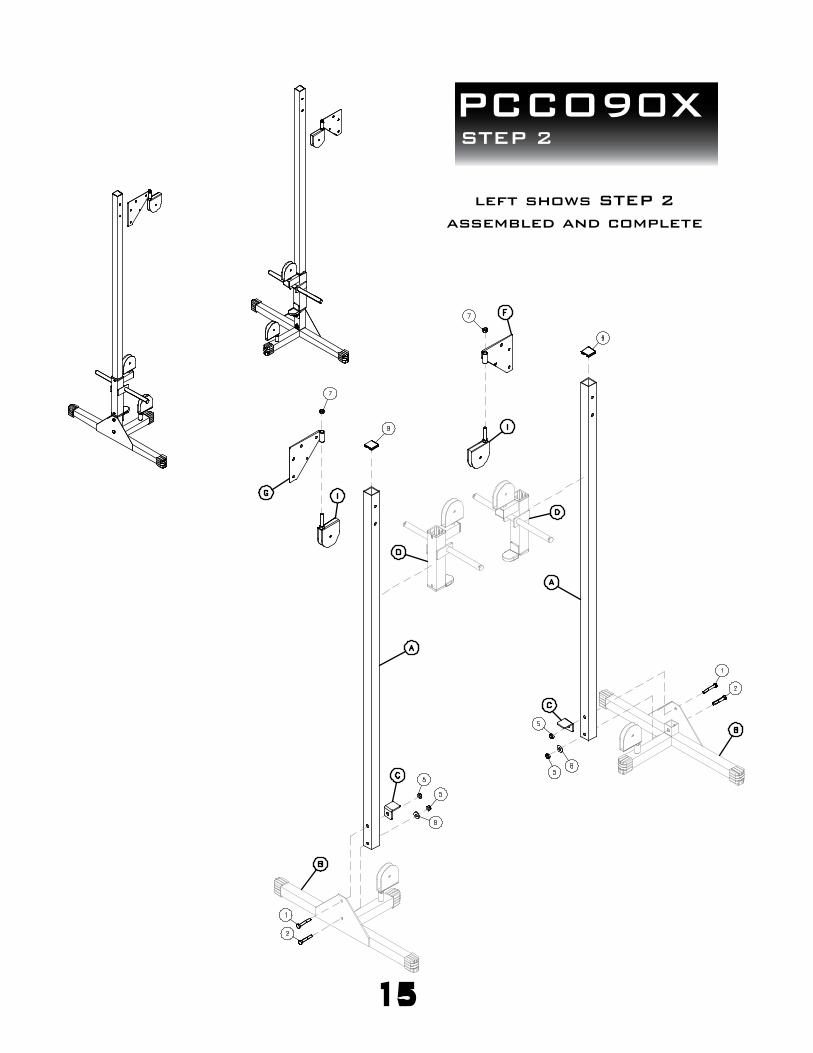
PCCO90XSTEP 2
15
left shows STEP 2
assembled and complete

PCCO90XSTEP 3
BE CAREFUL TO ASSEMBLE ALL COMPONENTS
IN THE SEQUENCE THAT THEY ARE PRESENTED.
NOTE:
finger tighten all hardware in this step. DO NOT wrench tighten
until the last step. some components may be PRE-ASSEMBLED.
nylon lock nuts will not fully screw onto bolts, must wrench tighten.
3A. attach cross beam (J) to the vertical frame (A) on the
left side using left support bracket (G) and a
connecting bracket (E) using a total of:
4 - (#1) M12X75mm hex head bolt
4 - (#5) M12 nylon lock nut
3B. attach cross beam (J) to the vertical frame (A) on the
right side using right support bracket (F) and a
connecting bracket (E) using a total of:
4 - (#1) M12X75mm hex head bolt
4 - (#5) M12 nylon lock nut
16

PCCO90XSTEP 3
17
left shows STEP 3
assembled and complete

PCCO90XSTEP 4
BE CAREFUL TO ASSEMBLE ALL COMPONENTS
IN THE SEQUENCE THAT THEY ARE PRESENTED.
NOTE:
this step is intended to show you where the pulleys need to be installed
and what hardware you will need to install them. however, you must
install the pulleys the same time you route the cables which can be
found on the next step
4A. a pulley will be attached to both of the two pulley
holders (I) at the base of your PCCO90X using a
total of:
2 - (#12) 110mm pulley
2 - (#4) M10X40mm hex head bolt
2 - (#6) M10 nylon lock nut
4B. a pulley will be attached to both of the two mid pulley
holders (H) attached to the weight frames (D) using a
total of:
2 - (#12) 110mm pulley
2 - (#4) M10X40mm hex head bolt
2 - (#6) M10 nylon lock nut
4C. a pulley will be attached to both of the two mid pulley
holders (H) at the top of your PCCO90X using a
total of:
2 - (#12) 110mm pulley
2 - (#4) M10X40mm hex head bolt
2 - (#6) M10 nylon lock nut
4D. a pulley will be attached in between the connecting
brackets (E) and left support bracket (G) and right
support bracket (F) using a total of:
2 - (#12) 110mm pulley
2 - (#17) 5/8” pulley spacer
2 - (#3) M10X75mm hex head bolt
2 - (#6) M10 nylon lock nut
18
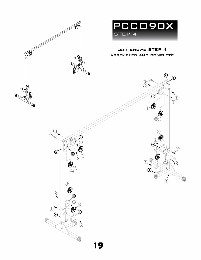
PCCO90XSTEP 4
19
left shows STEP 4
assembled and complete
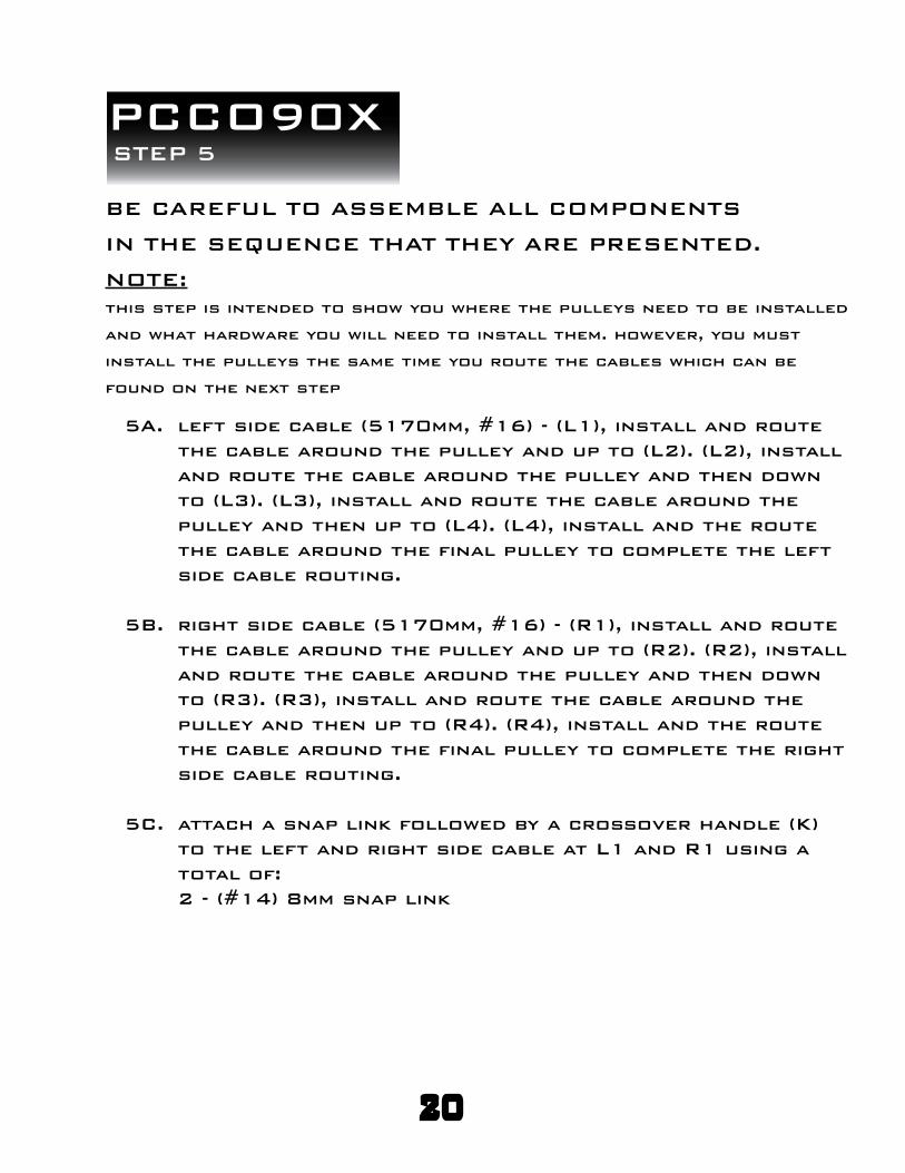
PCCO90XSTEP 5
BE CAREFUL TO ASSEMBLE ALL COMPONENTS
IN THE SEQUENCE THAT THEY ARE PRESENTED.
NOTE:
this step is intended to show you where the pulleys need to be installed
and what hardware you will need to install them. however, you must
install the pulleys the same time you route the cables which can be
found on the next step
5A. left side cable (5170mm, #16) - (L1), install and route
the cable around the pulley and up to (L2). (L2), install
and route the cable around the pulley and then down
to (L3). (L3), install and route the cable around the
pulley and then up to (L4). (L4), install and the route
the cable around the final pulley to complete the left
side cable routing.
5B. right side cable (5170mm, #16) - (R1), install and route
the cable around the pulley and up to (R2). (R2), install
and route the cable around the pulley and then down
to (R3). (R3), install and route the cable around the
pulley and then up to (R4). (R4), install and the route
the cable around the final pulley to complete the right
side cable routing.
5C. attach a snap link followed by a crossover handle (K)
to the left and right side cable at L1 and R1 using a
total of:
2 - (#14) 8mm snap link
20
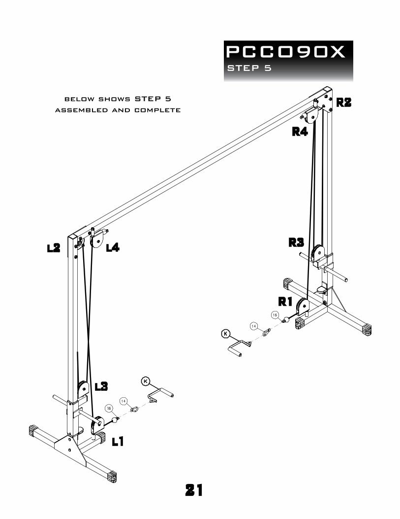
PCCO90XSTEP 5
21
below shows STEP 5
assembled and complete
l1
l2
l3
l4
R1
R2
R3
R4
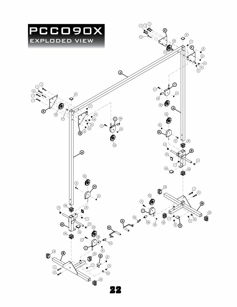
PCCO90XEXPLODED VIEW
22

PCCO90XNOTES
23

PCCO90X
1900 S. Des Plaines Ave.
Forest Park, IL 60130
Phone:(708)427-3555
Fax:(708)427-3556
Hours: M-F 8:30 - 5:00 CST
S/N # - - - -
please write your serial number in the boxes below
c Copyright 2011. Body-Solid. All rights reserved. Body-Solid reserves the right to change design and speci!cations when we feel it will improve the product. Body-Solid machines maintain several patented and patent pending features and designs. All rights reserved on all design patents and utility patents.
Body-SolidBuilt for Life
®
www.bodysolid.com
24
1900 S. Des Plaines Ave.
Forest Park, IL 60130
Phone:(708)427-3555
Fax:(708)427-3556
Hours: M-F 8:30 - 5:00 CST