Embed Size (px)
Citation preview

Instructions Manual MIF-2400/02-I [09-2008]
SERIES 66
Submersible electropumps for deep wells
This manual contains important instructions and warnings. You must read them before mounting, making the electrical connections and starting up. You must also comply with the
instructions for the components related to this pump.
Please remember that this Manual must be kept close to the motor pump group.

SERIES 66
Index
1 GENERAL ITEMS ...................................................... 3
2 SAFETY ..................................................................... 3 2.1 SIGNALLING OF WARNINGS IN THIS MANUAL ................. 3 2.2 PERSONNEL QUALIFICATIONS AND INSTRUCTION.......... 3 2.3 RISKS OF FAILING TO COMPLY WITH THE SAFETY INSTRUCTIONS................................................................. 3 2.4 CONSCIENTIOUS SAFETY AT WORK............................. 3 2.5 SAFETY INSTRUCTIONS FOR USERS AND SERVICE PERSONNEL .................................................................... 3 2.6 SAFETY INSTRUCTIONS FOR MAINTENANCE, INSPECTION AND ASSEMBLY WORK....................................................... 4 2.7 MODIFICATIONS AND ARBITRARY MANUFACTURE OF SPARE PARTS .................................................................. 4 2.8 UNAUTHORISED OPERATION MODES ........................... 4
3 TRANSPORT AND STORAGE.................................. 4 3.1 TRANSPORT AND HANDLING ...................................... 4 3.2 PROVISIONAL STORAGE/CONSERVATION..................... 4
4 GROUP DESCRIPTION............................................. 4 4.1 GENERAL DESCRIPTION ............................................ 4 4.2 DENOMINATION........................................................ 4 4.3 FORM OF CONSTRUCTION ......................................... 4 4.4 NOISE. PERMITTED LEVELS ....................................... 4
5 INSTALLATION ......................................................... 5 5.1 CHECK BEFORE ASSEMBLY........................................ 5 5.2 GROUP POSITIONING ................................................ 5
5.2.1 Location in perforation or deep well ...............5 5.2.2 Catchment location........................................5 5.2.3 Location in pipe .............................................6 5.2.4 Equipment installation....................................6
5.3 PIPE JOINT .............................................................. 6 5.4 ELECTRICAL MAINS CONNECTION ............................... 7
5.4.1 Rotation direction. Check...............................7 6 START-UP ................................................................. 7
6.1 FIRST START-UP ...................................................... 7 6.1.1 Lubricant........................................................7 6.1.2 Filling (priming) of the pump ..........................7 6.1.3 Final control ...................................................7 6.1.4 Start-up..........................................................7 6.1.5 Shutdown.......................................................7
6.2 SERVICE LIMITS ....................................................... 8 6.2.1 Start-up frequency .........................................8 6.2.2 Temperature of the liquid to be pumped........8 6.2.3 Density of the liquid to be pumped ................8
6.3 STARTING UP AFTER STORAGE .................................. 8
7 MAINTENANCE/CONSERVATION............................ 8 7.1 GENERAL INSTRUCTIONS........................................... 8 7.2 MAINTENANCE/INSPECTION ....................................... 8
7.2.1 Lubrication .................................................... 8 7.3 EMPTYING/DRAINAGE ............................................... 8 7.4 DISMOUNTING.......................................................... 8
7.4.1 Fundamental instructions/observations......... 8 7.4.2 Pump ............................................................ 8
7.5 ASSEMBLY............................................................... 9 7.5.1 Pump ............................................................ 9 7.5.2 Tightening torque of the screws/nuts ............ 9
7.6 RECOMMENDED SPARE PARTS ................................. 10 7.7 PREVENTATIVE MAINTENANCE.................................. 10
8 TROUBLE-SHOOTING ............................................ 11
9 ANNEXES................................................................. 12 9.1 SECTIONAL PLANS .................................................. 12

SERIES 66
3
1 General items This KSB ITUR pump has been developed in line with state-of-the-art technology,
manufactured with great care and put through stringent Quality Control. The present Instructions Manual will provide you with knowledge of the pump and the ways it can be applied.
It contains important instructions to operate the pump appropriately and profitably. It is important to comply with the manual in order to guarantee reliability and a long useful life for the pump, whilst avoiding any possible risks.
This manual does not include any local regulations or any instructions with regards to assembly personnel, which the user shall be responsible for.
This group cannot be used in conditions in excess of those established in the technical documentation with regards to the liquid to be pumped, flow, speed
(rpm), density, pressure and temperature, and also the motor power or anything else set out in the instructions manual and contractual documentation. Check with the manufacturer as appropriate.
The factory plate shows the model/size, the main service data and the manufacture number of the pump. Please include these data in any queries, subsequent orders or requests for spare parts.
Should you require further details or have a breakdown problem, please contact the nearest KSB ITUR service agent.
2 Safety This instructions manual contains fundamental indications which must be complied with in assembly, service and maintenance. It must be read by assembly personnel, competent technical personnel and users before installing and starting up, and it must be available at all times at the place of location of the machine. Proceed not only in line with this main safety chapter, but also observing the instructions described in other similarly important safety points.
2.1 Signalling of warnings in this manual All instructions in this manual which may involve personal hazard if not complied with are indicated with a general hazard sign.
Safety instructions which may involve a hazard to people and facilities if not complied with in accordance with ISO 7000-0434.
Safety instructions to prevent electrical hazards in accordance with IEC 417-5036.
Safety instructions which may affect the equipment and its operation if not complied
with.
The details shown directly on the machine, such as:
- Rotation direction arrow
- Fluid connections identifications
These must be complied with, and conserved in a manner which ensures they are legible.
2.2 Personnel qualifications and instruction
All Service, Maintenance, Inspection and Assembly personnel must be duly qualified. The terms regarding responsibility, competence and supervision of personnel must be regulated by the user in an exact manner.
Note
Any personnel lacking appropriate know-how must be duly instructed. This preparation can be obtained upon request by the machine user to the manufacturer or supplier of the machine.
Finally, the user must ensure that all personnel have fully understood the content of the instructions manual.
2.3 Risks of failing to comply with the safety instructions
Failure to comply with the safety instructions may lead to risks both for people, the environment and the machine, and may lead to the loss of any entitlement to claims.
In particular, failure to comply may cause the following hazards:
- Failure of important machine/facility functions.
- Failure of the prescribed maintenance and conservation methods.
- Personal hazard resulting from electrical, mechanical or chemical effects.
- Danger to the environment due to escaping noxious products.
2.4 Conscientious safety at work
The safety instructions contained in this Manual must be observed, as must international prescriptions on Health and Safety at Work and any possible Safety Regulations at the workplace of the user.
2.5 Safety instructions for users and service personnel
- The installer must ensure that the parts of the machine which may create danger due to heat or cold are protected against accidental contact.
- The protection devices which prevent contact with moving parts (e.g. couplings) must not be removed whilst the machine is in service.
- Possible leaks (e.g. through the shaft sealing) of hazardous products must be channelled in such a manner as they do not present any risk to people or the environment, in line with corresponding legislation.
- Electrical hazard must be avoided (see details in the specific legislation of the country and/or the electricity supply company).
Note

SERIES 66
4
2.6 Safety instructions for maintenance, inspection and assembly work The user must ensure that all maintenance, inspection and assembly tasks are carried out by authorised, qualified, specialised personnel who have been sufficiently informed through careful study of the instructions manual.
The pump frame must have returned to environmental temperature. It must then be depressurised and emptied of liquid.
It is a fundamental principle that any work on the machine must be carried out whilst it is shutdown. It is essential to respect the pump shutdown procedure described in the instructions manual.
All pumps or motor pumps which pump hazardous materials must be
decontaminated.
Size
Nº of pump stages
Motor power [kW]
Serie
All safety and protection devices must be installed and put into operation as soon as work concludes.
Before starting up again, all that described in the First Start-Up section must be followed.
2.7 Modifications and arbitrary manufacture of spare parts The machine must not be modified or changed without prior agreement from the manufacturer. Only original spare parts and accessories approved by the manufacturer can guarantee safety. The use of other components may terminate any liability for consequences deriving from their use.
2.8 Unauthorised operation modes The safe service of the supplied pump can only be guaranteed through correct use, in line with section 4 of the Instructions Manual. The operation limits established in the Datasheet must not be exceeded under any circumstance.
3 Transport and storage 3.1 Transport and handling
The transport and handling of the equipment must be carried out using suitable means in line with the weight to be supported. The weight is generally
shown on the delivery note or on the factory plate; if it is not, and the equipment cannot be handled safely, please contact KSB ITUR.
When the pumps are dismounted from their transport pallet, suitable means must be used to ensure the stability of the equipment, until it is finally secured at
its definitive location.
Once disassembled, the equipment should be kept in a vertical position for transport, and
never supported by its ends.
The received material must be carefully inspected, with any failure or defect being made known to us.
3.2 Provisional storage/conservation During provisional storage, it is necessary to protect the parts with preservation products from contact with the low alloy liquid (e.g. grey casting, nodular
casting, etc). Preservation products available on the sector market can be used, in line with the manufacturer's instructions on application and disposal.
The pump, or motor pump, shall be deposited in a dry site where the relative humidity is as constant as possible.
When stored outside, it is necessary to keep the pump/motor pump in an impermeable box, ensuring it does not come into contact with external humidity.
Protect the stored product from humidity, dirt, parasites and unauthorised access. All openings must remain closed, and must not be opened until necessary during assembly.
Note
The shiny (mechanised) parts and surfaces of the pump must be protected from corrosion using silicone-free grease or oil.
The electric motor must be disconnected, the connection cables removed and the terminal box closed with its cover on.
The switchboards must be in vertical position and disconnected.
4 Group description 4.1 General description Multi-stage centrifugal pump with submerged motor. For cold, clean water, without abrasives or solid particles, in deep wells or in catchments. Manufactured in nominal diameters of 6”-8”-10”-12”-14”.
4.2 Denomination 66 13 / 6 / 92
4.3 Form of construction Pump: Radially-split multistage pump casing. Impeller closed with diffuser. Filter in suction.
Bearing bush: The pump shaft rotates on friction bearing bushes lubricated by the pumped liquid.
Shaft sealing: Not applicable to the pump.
Note Operation: Submerged electric motor refrigerated by the surrounding liquid.
4.4 Noise. Permitted levels The acoustic pressure level of these pumps is less than 90 dB (A) in any operation point (always above the minimum flow required for each size). The acoustic power is less than 100 dB (A).

SERIES 66
5
5 Installation The design of the pipe systems, anchorings and other installation areas corresponds to
other parties. KSB ITUR only offers details and comments as a help, but does not assume any responsibility with regards to the design, assembly and operation of any installation. We recommend that customers should check with a specialist in the design of castings, pipes, wells, etc, to supplement and interpret the information provided by KSB ITUR and to ensure proper operation.
5.1 Check before assembly The equipment must be suspended from an amply sized casting. This casting must be
completely smooth and flat.
The attachment to the casting must not involve tension in the column pipe.
5.2 Group positioning Location
This type of pumps is generally installed in three different ways:
1.- Perforation or deep well
2.- Catchment from the channel, reservoir or similar.
3.- Pipe
5.2.1 Location in perforation or deep well
Before proceeding to install, check the following:
1- The depth of the well must be greater than the length of the equipment, ensuring that dirt does not cover the motor when decanting.
2- The well must be completely vertical and with sufficient effective interior diameter for the positioning of the equipment.
3- The gaging, cleaning and temperature of the well liquid.
4- The interior diameter of the well must be such that the speed of the liquid
throughout the motor is greater than 0.2-0.5 m/s, in line with the size and power of the motor. Check the motor manual. Should the speed be lower, use a suction hood. SEE FIGURE.
Gaging involves knowing the real flow of liquid which can be extracted, and the different levels established at different flows. When the level drops due to excess extracted flow, pressure oscillations will be produced in discharge as of a certain level, indicating that the extracted flow should be reduced.
The gaging values must be provided by the constructor of the well.
As a general rule, the minimum well level must not drop below 2 metres above the pump.
It is necessary to extract the sludge and sand produced during perforation in order to clean properly.
The temperature of the liquid should not exceed 25ºC. Should it be exceeded, the
available motor power shall be lower than the nominal power.
For the protection of the equipment, we recommend positioning three sensors in the well with the following functions: Note
1. The 1st or common must be positioned below the minimum level of the motor.
2. The 2nd located at least 2m above the pump, to stop due to a lack of water.
3. The 3rd pump start-up, as high as possible in order to prevent an excessive number of motor start-ups. Check the motor manual.
FOOT VALVE
ELECTROPUMP
CABLE GLAND
MOTOR GUIDE BOLTS
SUCTION HOOD
Note
Note
5.2.2 Catchment location
When catchment is made, bear in mind the positioning of a suction hood, preferably with a filter installed. SEE FIGURE.
The interior diameter of the hood must be such that the speed of the liquid throughout the
motor is greater than 0.2-0.5 m/s, in line with the size and power of the motor. Check the motor manual.
Note
Note The minimum distance from the filter to the bottom must be 300 mm and the liquid level must not drop below the minimum submergence level of the equipment.

SERIES 66
6
Optionally, the pump can be positioned horizontally. Depending on the type of motor,
this position is not always possible; please ask.
5.2.3 Location in pipe
When this type of equipment is positioned in a facility as an overweight element inside a pipe, it is important to take into consideration horizontality, fluid speed next to the motor, suction pressure and liquid temperature.
5.2.4 Equipment installation
Measurement items and tools
Apart from the usual tools, the following are necessary:
- Elevation machinery.
- Equipment suspension elements in the pipe during assembly.
- Wooden plugs to support the pieces without them touching the floor.
- Joints and pins to join the pipes (column with flanges).
- Elements (tapes, fixtures, etc.) for electrical connection.
- Megaohmeter, 500 V CC scale >200 MOhms.
- Amperemeter.
- Voltmeter, scale 500 V CA.
- Attachment clip
Electrical connection of the motor and cabling
All the cables must be disconnected from the mains or the power supply before proceeding with any operation.
Before positioning the pump, check the level of liquid in the motor and the tightness of the motor glands (where fitted).
Do not tighten the gland above the value recommended by the manufacturer.
Excessive tightness may damage the connection cable.
There is a range of suitable systems on the market to make a seal tight junction between cables, such as:
- Moulding in resins
- Torque pipes by way of heat
- Special adhesive tapes
Whatever the system used, follow the manufacturer's instructions when installing.
The base of a good connection is the correct joining of the copper nuclei, to which end we recommend using tubular copper hose-type connectors, of suitable size for the cable, in order to achieve a joint of low electrical resistance.
Make measurements with the megaohmeter for each installed section and note them down. A small drop is normal, depending on the length and type of cable. Should any strange reading come about, it is probable that there is damage to the cables. Any damage should be located and repaired before continuing with the installation.
In the event of cables not supplied by KSB ITUR, select the cable to prevent heating or voltage drops in excess of 3% of the nominal value.
Isolation resistance: The value measured in the megaohmeter must never be lower than
2 MOhms with a cold circuit.
Installation of pump and column Note Once the electrical connection of the cable is complete, proceed as follows:
- Suspend the pump with a crane, then introduce it in the catchment and support on the attachment element. Join the first pipe section, not forgetting to position the joints.
- Secure the cables to the column.
- Lift the equipment, remove the support elements in the mouth of the pipe. Bring the equipment down carefully, ensuring there is no contact with the cables, until it is supported on the end of the pipe section.
- Repeat the process with the other pipe sections.
Never use the motor cable to support, transport, handle or install the equipment.
Note
5.3 Pipe joint In no case can the pump be used as a fixed point for the pipes.
The position of the flanges must be totally parallel with their concentric shafts, in order to minimise strain in the pump necks, which may lead to deformation. The screws or studs must pass easily through the holes of the flanges. Do not forget to place seals at the joints.
The pipe system must at no time exercise force (due to connection, thermal variation, etc.) in the pump.
The short pipes must be of at least the diameter of the pump connections. The diameter of long pipes is, in some cases, determined by economic criteria.
Transition pieces at larger diameters must have an extension angle of around 8°, in order to prevent pressure drops.
The thermal expansions of the pipes must be compensated with suitable measures, in order not to exceed the maximum strains permitted on the pump.
Note
The diameters of the pipes, valves and accessories must be calculated in line with the load losses envisaged in the installation, meaning the fluid discharge speeds in the pipes will be: from 2 to 3 m/s
Exceeding the admitted strains of the pipes may lead to leaks in the pump and to the fluid escaping. Hazard of death with hot liquids!
The suction and discharge nozzle covers of the pump must be removed before connecting the pipes.
Before starting up a new installation, it is necessary to thoroughly clean the tanks, pipes and accessories by brushing and blowing. Welding material, scales and other impurities are often cast off some time after.
In order to prevent the rotation of the pumps in inverse direction (danger of the impeller
breaking out), a retention valve must be placed in the discharge pipe.
Note
Note
Note
SERIES 66
7
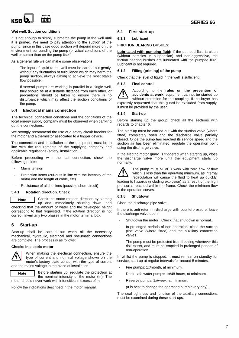
Wet well. Suction conditions
It is not enough to simply submerge the pump in the well until it is primed. We need to pay attention to the suction of the pump, since in this case good suction will depend more on the environment surrounding the pump (physical conditions of the well or sump) than on the pump itself.
As a general rule we can make some observations:
- The input of liquid to the well must be carried out gently, without any fluctuation or turbulence which may harm the pump suction, always aiming to achieve the most stable flow possible.
- If several pumps are working in parallel in a single well, they should be at a suitable distance from each other, or precautions should be taken to ensure there is no disturbance which may affect the suction conditions of the pump.
5.4 Electrical mains connection The technical connection conditions and the conditions of the local energy supply company must be observed when carrying out the connections.
We strongly recommend the use of a safety circuit breaker for the motor and a thermistor associated to a trigger device.
The connection and installation of the equipment must be in line with the requirements of the supplying company and applicable regulations (safety, installation...).
Before proceeding with the last connection, check the following points:
- Mains tension
- Protection items (cut-outs in line with the intensity of the motor and the length of cable, etc).
- Resistance of all the lines (possible short-circuit)
5.4.1 Rotation direction. Check
Check the motor rotation direction by starting up and immediately shutting down, and
checking that the amount of water and the developed height correspond to that requested. If the rotation direction is not correct, invert any two phases in the motor terminal box.
6 Start-up Start-up shall be carried out when all the necessary mechanical, hydraulic, electrical and pneumatic connections are complete. The process is as follows:
Checks in electric motor
When making the electrical connection, ensure the type of current and nominal voltage shown on the motor's factory plate concur with the type of current
and the mains voltage in the place of installation.
Before starting up, regulate the protection at the nominal intensity of the motor (In). The
motor should never work with intensities in excess of In.
Follow the indications described in the motor manual.
6.1 First start-up 6.1.1 Lubricant
FRICTION BEARING BUSHES:
Lubricated with pumping fluid: If the pumped fluid is clean (without particles in suspension) and non-aggressive, the friction bearing bushes are lubricated with the pumped fluid. Lubricant is not required.
6.1.2 Filling (priming) of the pump
Check that the level of liquid in the well is sufficient.
6.1.3 Final control
According to the rules on the prevention of accidents at work, equipment cannot be started up without protection for the coupling. If the buyer has
expressly requested that this guard be excluded from supply, it must be provided by the user.
6.1.4 Start-up
Before starting up the group, check all the sections with regards to chapter 6.
The start-up must be carried out with the suction valve (where fitted) completely open and the discharge valve partially closed. Once the pump has reached its service speed and the suction air has been eliminated, regulate the operation point using the discharge valve.
If the electric motor guard is triggered when starting up, close the discharge valve more until the equipment starts up normally.
The pump must NEVER work with zero flow or flow which is less than the operating minimum, as internal recirculation will cause the fluid to heat up quickly,
leading to hazards (including explosion) as a result of the high pressures reached within the frame. Check the minimum flow in the operation curves.
6.1.5 Shutdown Note
Close the discharge pipe valve.
If there is anti-return in discharge with counterpressure, leave the discharge valve open.
- Shutdown the motor. Check that shutdown is normal.
- In prolonged periods of non-operation, close the suction pipe valve (where fitted) and the auxiliary connection valves.
- The pump must be protected from freezing whenever this risk exists, and must be emptied in prolonged periods of non-operation.
If, whilst the pump is stopped, it must remain on standby for service, start up at regular intervals for around 5 minutes.
- Fire pumps: 1x/month, at minimum.
Note - Drink-safe water pumps: 1x/48 hours, at minimum.
- Reserve pumps: 1x/week, at minimum.
(It is best to change the operating pump every day).
The seal tightness and function of the auxiliary connections must be examined during these start-ups.

SERIES 66
8
6.2 Service limits 6.2.1 Start-up frequency
In order to prevent abnormally high temperatures and overloading of the motor, pump, coupling, seals, etc, the start-up frequencies indicated below must not be exceeded:
MOTOR POWER MAX. START-UPS/HOURUp to 3 kW 20 From 4 to 11 kW 15 From 11 to 45 kW 10 From 45 kW 5
6.2.2 Temperature of the liquid to be pumped
Never operate the pump at a temperature higher than that shown in the data sheet
and/or factory plate. See 5.2.1.
6.2.3 Density of the liquid to be pumped
The power absorbed by the pump increases in direct proportion to the density of the impelled liquid. In order to prevent overloading in the motor, pump and coupling, this intensity must not exceed that shown in the order.
6.3 Starting up after storage If the storage and/or shutting down of the pump has been for a prolonged period of time (over 6 months), it is necessary to: - Check the state of the joints. - Check the state of the bearing bushes. - Check all the auxiliary and electric connections. - Check the motor liquid. - After a short storage period, simply turn the pump shaft
manually to unlock the rotor equipment, and check the motor liquid.
- Follow the specific post-storage instructions in the motor manuals and other items.
- Observe all the steps shown in the "Start-up" section.
If the equipment is to be stopped for a certain period of time and there is the possibility of
freezing temperatures, it is necessary to completely drain the pump in order to prevent any deterioration from the freezing of the contained fluid, or increase the proportion of anti-freeze.
7 Maintenance/Conservation 7.1 General instructions Before dismounting, ensure that:
The motor must not be started up involuntarily, and so must be disconnected from the grid (e.g. removing cut-outs, unplugging, disconnecting the
automatic circuit breaker, etc.) or the start-up batteries (disconnect operating energy).
The pump is free of pumped fluid, cleaning it internally with appropriate liquid whenever it is a hazardous fluid (hot, contaminant, inflammable…).
It is necessary to uninstall the equipment before dismounting the pump, column sections, etc. To do this, proceed in reverse order to that described in point 5.2.4 of this manual.
7.2 Maintenance/inspection
7.2.1 Lubrication
Pump
The pump rotates on friction bearing bushes. These bearings must always be lubricated and cooled.
If the pumped fluid is clean (without particles in suspension) and non-aggressive, the friction bearings are lubricated with the pumped fluid. Lubricant is not required.
Motor
The lubrication of the motor is carried out by mixing water with anti-freeze, acting as a lubricant, refrigerant and inhibitor of corrosion. Generally, only clean water can be used, since it remains inertized following small corrosion.
Note
It is very important that there is no air inside the motor, which should be discharged whenever possible.
Follow the specific instructions of the motor manual.
7.3 Emptying/Drainage
The emptying and drainage of pumps used to expel liquids which are a health hazard must be carried out in such a way as there is no risk to people or to the
environment, in line with legislation. If necessary, use protective clothing and mask.
7.4 Dismounting
7.4.1 Fundamental instructions/observations
Before dismounting, ensure the pump cannot be started up.
Note
The suction and discharge valves must be closed.
The pump frame must have returned to environmental temperature.
Note The pump frame must be depressurised and emptied.
Comply with all safety measures in accordance with 7.1. When working on the motor, also take into account the rules and instructions of the manufacturer.
7.4.2 Pump
It is practical to dismount the entire pump in order to extract the bearing bushes, shaft, etc.
See the attached sectional plans.
Before dismounting, mark the cells with their order number within the pump, and mark their relative position by way of a vertical mark in the contact zone. The dismounting process depends on the type of pump:

SERIES 66
9
Pumps type 1 Sizes 6663, 6664, 6665 and 6685 correspond to this type. To dismount this type of pump, proceed as follows:
- Release the coupling setscrews, remove the pump-motor attachment nuts and separate both elements, taking the precaution to mark the position of the coupling on both shafts.
- Remove the key from the motor side of the shaft.
- Release the nuts from the rods and extract the attachment pins in the suction casing.
- Separate the equipment discharge casing and extract the cover and the bearing bushes.
- Remove the circlip from the shaft, extract the diffuser and then the impeller and its key.
- Extract the cell with its wear ring (where fitted).
- Repeat the three previous steps for each existing cell.
- Extract the last diffuser and the corresponding impeller. At this moment the suction casing will be free, along with its wear ring.
Pumps type 2 Sizes 6606, 6666, 6667, 6608, 6609, 6688, 6699, 6610, 6611, 6612, 6613, 6615, 6616, 6619, 6620 correspond to this type.
To dismount this type of pump, proceed as follows:
- Remove the attachment nuts from the suction casing.
- Separate pump and motor.
- Release the nuts from the rods and extract the suction casing pins.
- Extract the discharge casing with the bus bearing.
- Extract the first cell with its bearing bush and wear ring (where fitted).
- Repeat the extraction of cells, impellers and casings for each stage.
- Unthread the anti-sand hood and push the shaft to extract it with the coupling. At this moment the suction casing will be free, along with its bearing bush.
7.5 Assembly 7.5.1 Pump
Check the correct positioning of pieces, especially impellers and casings.
Pumps type 1
To do this, proceed in reverse order to that described for dismounting the pumps.
Pumps type 2
When mounting the setscrew on the motor side of the coupling, do not tighten it against the shaft, but rather leave it separated by half a turn. Using a pointed tool, secure it with two points at the confluence of the coupling thread and the setscrew.
Additional observations:
- All the joints intervening in the dismounting of the pump must be renewed.
- Do not forget to position all the safety and protection elements, such as coupling guards, before starting up the equipment.
7.5.2 Tightening torque of the screws/nuts
Steel Stainless
steel
ISO Metric thread
Tightening Torque in [N·m]
(for non-lubricated thread)
M4 3.1 2.15 M5 6.1 4.25 M6 10.4 7.3 M8 25.2 17.7 M10 49.5 34.8 M12 85.2 59.9 M16 211 148 M20 412 290 M24 710 276 M27 1050 409 M30 1420 554
Note

SERIES 66
10
7.6 Recommended spare parts
Recommended spare parts (1) Piece denomination Reference Nº Start-up 2 years 5 years
Joints (set) --- 1 2 5 Wear ring (set) 502 1 2 Friction bearing bush (set) 545 1 2 Impeller nut 922 1 2 Circlip (set) 932 1 2 Key (set) 940 1 2 Pump shaft(s) (set) 211 1 Impeller 230 1 (1) Amounts recommended for a continuous service pump.
7.7 Preventative maintenance
Nº DESCRIPTION OF THE OPERATION TO BE CARRIED OUT
PROCEDURE REGULARITY CONSEQUENCE
1 Check for leaks between exterior flanges Visual inspection Monthly 8
2 Check pressure and consumption Visual inspection Monthly
3 Complete pump check
Checking and dismounting the
pump, see point 7 of the manual
In accordance with use 1, 2, 5, 6, 7
4 Check functional characteristics loss
Instrument reading In accordance with use
Check the installation, 3
5 Check tightness of connecting bolts for motor, pump, support, etc. Manually Every time it is
removed
6 Check for wear of the impeller and rings Dismount casing, Visual inspection
Every time it is removed
7 Check for wear of the shaft and bearing bushes Dismount, Visual inspection
Every time it is removed
8 Change the joints Visual inspection Every time it is removed

SERIES 66
11
8 Trouble-shooting
The pump does not move the fluid | Insufficient pressure or flow | | Excessive absorbed power | | | Excessive vibrations and noise | | | | The pump does not start up | | | | | Cause Solution
x x Discharge valve closed or poorly regulated Open it or regulate it correctly
x Incorrect pump rotation direction Change the motor connections
x x Sieve filter obstructed Clean it
x Shaft or coupling broken Change it
x Air comes in through the suction pipe,. Check gaging
x Retention valve obstructed Clean it
x x Maximum height generated by the pump lower than that required by the installation or counter pressure too high.
Increase the rotation speed. If this is not possible, a larger impeller or larger pump needs to be assembled. Please ask
x Rotation speed incorrect Check the frequency and grid voltage of the motor
x Pipe obstruction Clean the pipes
x x Impeller obstructed, deteriorated or imbalanced Dismount the impeller, and inspect, balance or change it.
x Wear rings deteriorated or incorrectly assembled Dismount the rings and change them
x Liquid viscosity or density greater than normal. Reduce the design point or change the motor
x Excess solids and sand in the fluid Clean the well or filter the fluid
x Obstruction inside the pump, impeller or nozzles Dismount the pump and clean
x The real height to be generated by the pump is lower than that of the design point, meaning the flow and power are greater
Partially close the discharge valve
x x Ball bearings deteriorated, poorly assembled and poorly lubricated
Change them, check their assembly, mount correctly or lubricate them
x Excessive contact in rotating parts Dismount the pump and check its elements are correctly assembled
x Misaligned or deformed shaft Dismount it and replace it
x Lack of rigidity in the foundations or anchor bolts loose Make new foundations or tighten the bolts
x x Pump with cavitation or incoming air. Check gaging. Improve the suction. Please ask.
x Insufficient pipe diameters Larger diameter pipes, whenever possible
x Impellers in contact or blocked If the blocking is due to sand, turning the equipment in the opposite direction for a moment may solve the problem. If it does not, dismount it.
x Motor disconnected, low voltage or absence of phase Check the connections, cables and control and/or protection devices of the motor

SERIES 66
12
9 Annexes 9.1 Sectional plans
Sectional C-1303 Sizes 6664, 6665, 6685
560
171
211
230
107 671 545.1
920.1
554
932
551
940.2
108
905
502
400
143
904.1
844
904.2
940.1
106
800
751545.2753411752902920.2107
751545.2753411752902920.2107
Version with valve and flange an n
Ref. ENGLISH 106 Suction casing107 Discharge cas108 Stage casing 143 Suction strain171 Diffuser 211 Pump shaft 230 Impeller 400 Gasket 411 Circular gaske502 Wear ring 545 Friction bearin551 Spacer washe554 Flat washer 560 Pin 671 Vacuum break751 Valve body 752 Valve seat 753 Valve shutter 800 Motor 844 Rigid coupling902 Bolt 904 Setscrew 905 Tie bolt 920 Nut 932 Circlip 940 Key
Version with valve d threaded connectio
ing
er
t
g bush r
er box

SERIES 66
Sectional C-1304 Sizes 6608, 6609, 6610, 6611, 6666, 6667
560
131
211
230
107
673
545.3
920.2
554.2
554.1
922
545.2
940.2
112
525
905
502
400
904.3
143
271
545.1
903
904.2
940.1
106
844
904.1
901
920.1
800
751545.4753411752902920.3107
751
545.4
753
411
752
902
920.3
107
Version with valve and flange an n
Version with valve d threaded connectio
Ref. ENGLISH 106 Suction casing 107 Discharge casing 112 Pump bowl 131 Inlet ring 143 Suction strainer 211 Pump shaft 230 Impeller 271 Sand guard 400 Gasket 411 Circular gasket 502 Wear ring 525 Spacer sleeve 545 Friction bearing bush 554 Flat washer 560 Pin 673 Vent filter 751 Valve body 752 Valve seat 753 Valve shutter 800 Motor 844 Rigid coupling 901 Hexagonal head screw 902 Bolt 903 Plug 904 Setscrew 905 Tie bolt 920 Nut 922 Impeller nut 940 Key
13

SERIES 66
14
Sectional C-1305 Sizes 6612, 6613, 6615
751545.4753411752902920.3107
751
545.4
753
411
752
902
920.3
107
107
560
131
230
211
400
673
545.3
920.2
554.2
554.1
922
545.2
940.2
112
525
905
502.2
502.1
904.3
143
271
545.1
903
904.2
940.1
106
844
904.1
901
920.1
800
Ref. ENGLISH 106 Suction casing 107 Discharge casing 112 Pump bowl 131 Inlet ring 143 Suction strainer 211 Pump shaft 230 Impeller 271 Sand guard 400 Gasket 411 Circular gasket 502 Wear ring 525 Spacer sleeve 545 Friction bearing bush 554 Flat washer 560 Pin 673 Vent filter 751 Valve body 752 Valve seat 753 Valve shutter 800 Motor 844 Rigid coupling 901 Hexagonal head screw 902 Bolt 903 Plug 904 Setscrew 905 Tie bolt 920 Nut 922 Impeller nut 940 Key
Version with valve and threaded connection
Version with valve and flange

SERIES 66
Sectional C-1306 Sizes 6616, 6618, 6619, 6620
751545.4753411752902920.3107
751
545.4
753
411
752
902
920.3
107
673 671 545.3 107
920.2
554.2
554.1
922
525.2
545.2
112
400
525.1
940.2
905
502.2
502.1
230
560
211
904.3
271
545.1
143
903
904.2
940.1
844
106
901
920.1
904.1
800
an nVersion with valve
and flange
Version with valved threaded connectio
Ref. ENGLISH 106 Suction casing 107 Discharge casing 112 Pump bowl 143 Suction strainer 211 Pump shaft 230 Impeller 271 Sand guard 400 Gasket 411 Circular gasket 502 Wear ring 525 Spacer sleeve 545 Friction bearing bush 554 Flat washer 560 Pin 671 Vacuum breaker cup 673 Vent filter 751 Valve body 752 Valve seat 753 Valve shutter 800 Motor 844 Rigid coupling 901 Hexagonal head screw 902 Bolt 903 Plug 904 Setscrew 905 Tie bolt 920 Nut 922 Impeller nut 940 Key
15

SERIES 66
16
Sectional C-1307 Sizes 6688, 6699
673
920.2
545.2
922
545.3
107
112
554.1
554.2
940.2
525
131
211
230
400
502
905
271
143904.3
560
800
920.1
901
904.1
844
106
940.1
904.2
545.1
903
271
545
301
525
751545.4753411752902920.3107
751
545.4
753
411
752
902
920.3
107
Ref. ENGLISH 106 Suction casing 107 Discharge casing 112 Pump bowl 131 Inlet ring 143 Suction strainer 211 Pump shaft 230 Impeller 271 Sand guard 301 Intermediate bearin400 Gasket 411 Circular gasket 502 Wear ring 525 Spacer sleeve 545 Friction bearing bus554 Flat washer 560 Pin 673 Vent filter 751 Valve body 752 Valve seat 753 Valve shutter 800 Motor 844 Rigid coupling 901 Hexagonal head sc902 Bolt 903 Plug 904 Setscrew 905 Tie bolt 920 Nut 922 Impeller nut 940 Key
an nVersion with valve
and flange
Version with valve d threaded connectio
g support
h
rew

SERIES 66
17
This page has been left blank on purpose.

SERIES 66
18
This page has been left blank on purpose.

SERIES 66
19
This page has been left blank on purpose.

WARRANTY KSB ITUR Spain, S.A. undertakes: To repair or replace at any of its ASSOCIATED TECHNICAL SERVICE CENTRES or at its factory in Zarautz, free of charge and for a period of 12 months as of the date of dispatch from our warehouses, any product which shows manufacture defects. This warranty will be reduced to 6 months for continuous or permanent service pumps. KSB ITUR Spain, S.A. shall not be liable for any direct or indirect damage which the product suffers as a result of defective installation, lack of maintenance, negligent handling, handling by unauthorised personnel, overloading or deficient functions. The responsibility of KSB ITUR Spain, S.A. is limited in all cases to the replacement, as speedily as possible, of the defective part, without it being in any way liable for other responsibilities or compensation.
CERTIFICATE OF COMPLIANCE WITH
EC MACHINERY DIRECTIVE KSB ITUR P.O. Box 41 – 20800 ZARAUTZ (Gipuzkoa) Spain
PRODUCT UNDER CERTIFICATION. PUMPS SERIES 66
EC DECLARATION OF CONFORMITY
KSB ITUR hereby declares, under its responsibility, that its aforementioned products (when supplied with a motor), to which this Declaration refers, are in line with European Directive 98/37/EC on the approximation laws of the Member States on machinery.
Applied harmonised standards:
EN 292 Part 1, EN 292 Part 2 and EN 809
MANUFACTURER'S
DECLARATION
KSB ITUR hereby declares that its aforementioned products (when supplied without a motor) are proposed for incorporation in machinery or assembled with other machines to form machinery covered by Directive 98/37/EC.
Warning is hereby given that the aforementioned products cannot be started up until the machinery in which they are to be incorporated has been declared to conform to the dispositions of the aforementioned Directive.
Applied harmonised standards:
EN 292 Part 1, EN 292 Part 2 and EN 809
Zarautz, September 2008
KSB ITUR Spain, S.A. P.O. Box 41 – 20800 ZARAUTZ (Gipuzkoa) Spain
9-20
08]
Post Head of Engineering
Name Ángel Fernández
MIF
-240
0/02
-I [0
Tel.: +34 943 899 899 – Fax +34 943 130 710 E-mail: [email protected] – www.ksb-itur.es