Embed Size (px)
Citation preview

Electrode Steam HumidifierElectrode Steam Humidifier
ÁHYL.ENsÈHYL.ENE-8881100
Manual

Page 2
A Word about Water Quality
The mode of operation of all electrode steam humidifiers is based on the fact that water containsminerals and is therefore conductive.
• "normal" tap water is ideal.
• but what is "normal" tap water exactly?
Users of HygroMatik units in the most diverse areas consider their tap water "normal."
HygroMatik typically defines "normal" as feed water with a conductivity between 200 and 500 µS/cm (microSiemens per centimeter) at 15° C.
Some areas, however, are supplied with tap water whose quality is outside the parameters spec-ified by HygroMatik. If the HygroMatik steam humidifier's control is not adjusted correctly in theseareas, the unit cannot perform optimally. For example, the electrodes could wear out particularlyquickly or the steam production could be too low.
The operational parameters set by HygroMatik in the factory are intended for normal tap water.However, they can very easily be reprogrammed to fit the special requirements of a particulararea. In addition, it is possible to install a plastic star in the cylinder in order to increase the lifespan of the electrodes or to provide a flushing mechanism to extend maintenance intervals.
Because of this you should monitor your new unit during initial operation. Make sure that it hasbeen properly installed and is operating to your satisfaction.
Consult your HygroMatik specialists. We will test the quality of your water and advise you oninstallation and initial operation. Your HygroMatik steam humidifier will be carefully adapted toyour particular application.
Certain computer programs contained in this product [or device] were developed by HygroMatikGmbH ("the Work(s)").
© Copyright HygroMatik GmbH
HyLine [03.07.2017]
Current version of this manual can be found at: www.hygromatik.co.uk
All rights reserved.
HygroMatik GmbH grants the legal user of this product [or device] the right to use the Work(s)solely within the scope of the legitimate operation of the product [or device]. No other right isgranted under this licence. In particular and without prejudice to the generality of the foregoing,the Work(s) may not be used, sold, licensed, transferred, copied or reproduced in whole or inpart or in any manner or form other than as expressly granted here without the prior written con-sent of HygroMatik GmbH.
Information in this manual is subject to change or alteration without prior notice.
Risk of electrical shock!Hazardous electrical high voltage!All electrical work to be performed by certified expert staff (electricians or expert personnel witheqivalent training) only.

1. Introduction ....................................................................................................................... 5
1.1 Typographic Distinctions ................................................................................................... 5
1.2 Documentation .................................................................................................................. 5
1.3 Symbols in Use ................................................................................................................. 6
1.3.1 Specific Symbols related to Safety Instructions ............................................................. 6
1.3.2 General Symbols ............................................................................................................ 6
1.4 Intended Use ..................................................................................................................... 6
2. Safety Instructions ............................................................................................................ 8
2.1 Guidelines for Safe Operation ........................................................................................... 8
2.1.1 General ........................................................................................................................... 8
2.1.2 Unit control ..................................................................................................................... 8
2.1.3 Unit operation ................................................................................................................. 8
2.1.4 Mounting, dismantling, maintenance and repair of the unit ............................................ 9
2.2 Electrical ............................................................................................................................ 10
2.2.1 Disposal after dismantling .............................................................................................. 10
3. Transport ............................................................................................................................ 11
3.1 Overview ........................................................................................................................... 11
3.2 Packing .............................................................................................................................. 11
3.3 Interim Storage .................................................................................................................. 11
3.4 Check for Complete and Correct Delivery of Goods ......................................................... 11
4. Operation and Installation ................................................................................................ 12
4.1 Mode of Operation ............................................................................................................. 12
4.2 Installation and Operation ................................................................................................. 12
5. Installation ......................................................................................................................... 15
5.1 Steam Humidifier Operating Environment ......................................................................... 15
5.1.1 Fitting measures ............................................................................................................. 17
5.1.2 Unit Dimensions HY05-HY45 ......................................................................................... 19
5.1.3 Unit Dimensions HY60-HY116 ....................................................................................... 20
5.2 Fan Unit (optional) ............................................................................................................. 21
5.2.1 Fan Unit Type VG ........................................................................................................... 21
5.2.2 Fan Unit Cover ............................................................................................................... 22
5.3 Absorption Distance BN .................................................................................................... 23
5.3.1 Determining the Absorption Distance ............................................................................. 23
5.3.2 Absorption Distance Nomogram .................................................................................... 25
5.4 Steam Manifold ................................................................................................................. 26
5.4.1 Notes on Installation ....................................................................................................... 26
5.5 Steam Line ........................................................................................................................ 30
5.6 Cover Plate ........................................................................................................................ 31
5.7 Condensate Hose .............................................................................................................. 32
5.8 Types of Installation .......................................................................................................... 32
5.9 Steam Solenoid Valves ..................................................................................................... 34
5.10 Unit Installation Check ..................................................................................................... 34
Page 3

6. Water Installation .............................................................................................................. 35
6.1 Operation with Softened Water ......................................................................................... 36
6.2 Water Supply ..................................................................................................................... 37
6.3 Water discharge ................................................................................................................ 38
6.4 HyFlow Provision (Special Model) ..................................................................................... 40
6.5 Water Installation Check ................................................................................................... 41
7. Electrical Connection ........................................................................................................ 42
7.1 Electrical Installation .......................................................................................................... 42
7.2 Cable Connections ............................................................................................................ 45
7.3 Fan Unit ............................................................................................................................. 46
7.4 Safety Interlock .................................................................................................................. 47
7.5 Wiring Diagram .................................................................................................................. 47
7.6 Electrical Installation Checklist .......................................................................................... 47
8. Commissioning ................................................................................................................. 48
9. Maintenance ....................................................................................................................... 50
9.1 Maintenance Work ............................................................................................................ 51
9.2 Access to Electrical Enclosure .......................................................................................... 52
9.3 Removing and Cleaning the Steam Cylinder .................................................................... 52
9.4 Electrode wear .................................................................................................................. 59
9.4.1 Original Electrode Lengths ............................................................................................. 59
9.4.2 Uneven Electrode Wear ................................................................................................. 60
9.5 Replacing Electrodes ........................................................................................................ 60
9.6 Cleaning the Blow- down pump ......................................................................................... 61
9.7 Cleaning the Water Inlet Solenoid Valve ........................................................................... 63
9.8 Cleaning the Water Inlet Solenoid Valve and HyFlow System Separator (special models only) ................................................................................................................................................. 64
9.9 Checking Cable Connections and Electrode Cables ......................................................... 65
9.10 Checking Hoses .............................................................................................................. 65
9.11 Checking Operation ......................................................................................................... 65
9.12 Dismantling ...................................................................................................................... 65
10. EC-Declaration of Conformity ........................................................................................ 66
11. Spare Parts ...................................................................................................................... 67
12. Fax Form - Order for spare parts ................................................................................... 72
13. Technical Specification .................................................................................................. 74
14. Exploded View ................................................................................................................. 76
15. View of housing ............................................................................................................... 77
Page 4

1. Introduction
Dear Customer,
Thank you for choosing a HygroMatik steam humidifier.
HygroMatik steam humidifiers represent the latest in humidifica-tion technology.
In order to operate your HygroMatik steam humidifier safely, pro-perly and efficiently, please read these operating instructions.
Employ your steam humidifier only in sound condition and asdirected. Consider potential hazards and safety issues and fol-low all the recommendations in these instructions.
If you have additional questions, please contact us:
Tel.: +49-(0)4193 / 895-0 (Main Number)
Tel.: +49-(0)4193 / 895-293 (Technical Support Hotline)
Fax: +49-(0)4193 / 895-33
e-mail: [email protected]
For all technical questions or spare parts orders, please be pre-pared to provide unit type and serial number (see name plate onthe unit).
1.1 Typographic Distinctions
• preceded by a bullet: general specifications
» preceded by an arrow: Procedures for servicing or maintenance which should or must be performed in the indicated order
Installation step which must be checked off
italics Terms used with graphics or drawings
1.2 Documentation
Retention
Please retain these operating instructions in a secure, alwaysaccessible location. If the product is resold, turn the documenta-tion over to the new operator. If the documentation is lost, pleasecontact HygroMatik.
Versions in Other Languages
These operating instructions are available in several languages.If interested, please contact HygroMatik or your HygroMatik dea-ler.
Page 5

1.3 Symbols in Use
1.3.1 Specific Symbols related to Safety Instructions
According to ANSI Z535.6 the following signal words are usedwithin this document:
DANGER indicates a hazardous situation which, if not avoided,will result in death or serious injury.
WARNING indicates a hazardous situation which, if not avoided,could result in death or serious injury.
CAUTION indicates a hazardous situation which, if not avoided,could result in minor or moderate injury.
NOTICE is used to address practices not related to physicalinjury.
1.3.2 General Symbols
This symbol is used whenever a situation requires special atten-tion beyond the scope of safety instructions.
1.4 Intended Use
The HygroMatik steamgenerator serves for steam production based onvarious water qualities or partially softened water (valid for all of theHygroMatik humidifier models). With the HeaterLine, HeaterCompact/Kit and HeaterSlim familiy of products, also fully desalinated water/cleaned condensate may be used.
Only use supply water featuring a conductivity of 125to1250 µS/cm.
Please note
Page 6

D1: Lower threshold
C1: Range of reduced conductivity (adjustments recommended)
A: Normal tap water
B: Range of heightened conductivity
C2: Range of high conductivity (adjustments recommended)
D2: Upper threshold
Proper usage also comprises the adherence to the conditionsspecified by HygroMatik for:
• installation • dismantling • reassembly • commissioning • operation• maintenance• disposal.
Only qualified and authorised personnel may operate the unit.Persons transporting or working on the unit must have read andunderstood the corresponding parts of the Operation and Main-tenance Instructions and especially the chapter 2. „SafetyNotes“. Additionally, operating personnel must be informed ofany possible dangers. You should place a copy of the Operationand Maintenance Instructions at the unit‘s operational location(or near the unit).
By construction, HygroMatik steam humidifiers are not qua-lified for exterior application.
Risk of scalding!Steam with a temperature of up to 100 °C is produced.Do not inhalate steam directly in order to avoid respiratorydamage!
Page 7

2. Safety InstructionsThese safety instructions are required by law. They promoteworkplace safety ans accident prevention.
2.1 Guidelines for Safe Operation
2.1.1 General
Comply with the accident prevention regulation „DGUV Regula-tion 3“ to prevent injury to yourself and others. Beyond that,national regulations apply without restrictions.
2.1.2 Unit control
Do not perform any work which compromises the safety of theunit. Obey all safety notes and warnings present on the unit.
In case of a malfunction or power grid disruption, switch off theunit immediately and prevent a restart. Repair malfunctionspromptly.
Restricted use.This unit is not designed for the use by persons (also children) with limited physical, sensory and mental abilities - or without knowledge and experience - unless they are supervised or trai-ned by a person, who is responsible for their safety. Supervise children in order to ensure that they will not play withthe unit.
2.1.3 Unit operation
Risk of scalding!In case of leaking or defective components, hot steam may exitin an uncontrolled manner.
In case of malfunction or electrical power disruption, switch offthe unit immediately and prevent from restart.
Page 8

Risk of material damage!The unit may be damaged if switchedon repeatedly following a malfunction without prior repair.Rectifydefects immediately!
The unit must not be operated on a DC power supply.
The unit may only be used connected to a steam pipe that safely trans-ports the steam (not valid device type MiniSteam).
Regularly check that all safety and monitoring devices are functioningnormally. Do not remove or disable safety devices.
2.1.4 Mounting, dismantling, maintenance and repairof the unit
The HygroMatik steam humidifier is IP20 protected. Make surethat the unit is not object to dripping water in the mounting loca-tion.
When installation is made in a room without a drain, safety pre-cautions must be taken in order for to shut off the humidifier‘swater supply in event of a leak.
Use genuine spare parts only.
After any repair work, have qualified personnel check the safeoperation of the unit.
Attaching or installing of additional components is permittedonly with the written consent of the manufacturer.
Page 9

2.2 Electrical
Risk of electrical shock!Hazardous electrical high voltage.Anywork on the electrical system may only be performed by quali-fied personnel.Disconnect unit components from electricalpower supply prior to work.After electrical installation or repairwork, test all safety mechanisms (such as grounding resi-stance).
Use only original fuses with the appropriate amperagerating.Regularly check the unit‘s electrical equipment. Promptlyrepair any damage such as loose connections or burnedwiring.Responsibility for intrinsically safe installation of theHygroMatik steam humififiers (steam generators) is incumbenton the installing specialist company.
2.2.1 Disposal after dismantling
The operator is responsible for the disposal of unit componentsas required by law.
Page 10

Page 11
3. Transport
3.1 Overview
Proceed carefully when transporting the steam humidifier inorder to prevent damage due to stress or careless loading andunloading.
3.2 Packing
Pay attention to the icons affixed to the packing box.
3.3 Interim Storage
Store the unit in a dry place and protect from frost.
3.4 Check for Complete and Correct Delivery ofGoods
Upon receipt of the unit, confirm that:
• model and serial number on the name plate match those specified in the order and delivery documents and
• the equipment is complete and all parts are in perfect condition
In case of damage during shipment or missing parts, immedi-ately notify the carrier or supplier in writing.
Time limits for filing freight claims with shipping companies are*:
* Time limits for some services subject to change.
Shipping company After receipt of goods
Carriers no later than 4 days
Parcel service immediately
Please note
Please note
Please note

4. Operation and Installation
4.1 Mode of Operation
The HygroMatik steam humidifier utilizes the conductivity nor-mally present in tap water for steam production. Electrodesinside an enclosed steam cylinder are immersed directly into thetap water. They are connected to the alternating current.
The conductivity of the water generates an electric currentbetween the electrodes. In this way, the electric power suppliedis converted directly into heat without energy loss.
The amperage is a function of the available voltage, theimmersed electrode surface area, the average distance betweenthe electrodes and the water conductivity. The steam output ofthe humidifier is determined by electric power usage, which isregulated by increasing or decreasing the immersed surfacearea of the electrodes.
Concurrently, a self-regulating control keeps conductivity withina specified range.
The steam produced has a temperature of about 100°C withminimal excess pressure ("pressureless steam"). It is largelyfree of minerals and germ-free. Mineral deposits typically remainbehind in the cylinder.
4.2 Installation and Operation
By pressing the control switch („Pos. I”) the humidifier is turnedon. When the controller specifies an increase in humidity, themain contactor is switched on and the electrodes (48) are sup-plied with power. The water inlet solenoid valve (25) feeds waterinto the steam cylinder (16+19).
As soon as the electrodes are immersed, the current begins toflow. The water is now heated. When the pre-selected output isreached, the control turns off the solenoid valve and interruptsthe water supply.
After a short heating up period, the water between the elec-trodes begins to boil and vaporize. The vaporization lowers thewater level in the steam cylinder, reducing the output provided.The inlet solenoid valve, equipped with a fine mesh filter, inter-mittently admits fresh water.
Humidifier power usage is continuously monitored. With a coldstart-up, the nominal current increases to 125% in order toachieve quick-start output parameters. This activates the elec-tronic overflow limiter which causes a partial draining of the cyl-inder. This reduces the immersed surface area of the electrodes,lowering power usage.
Page 12

Please also see Section „Exploded View“.
Location Designation
1 adapter
6 vent pipe
10 max. water level sensor electrode
14 water drain, discharge
16 steam cylinder
17 o-ring cylinder flange
18 cylinder flange and o-ring
25 solenoid valve water inlet
32 blow-down pump
35 o-ring
37 cylinder base
48 electrodes
48
Page 13

The concentration of dissolved salts increases over time, whichcan lead to a rise in the conductivity of the water. If this contin-ues, conductivity may increase until a short circuit occurs. Thiscould damage the unit, but in any case would significantlyreduce the life span of the electrodes.
For this reason, regular, periodic blow-downs of some of theconcentrated water are very important. Following this procedureas recommended provides stable cylinder water conductivity aswell as minimal water loss for the expected service life of the cyl-inder.
Water blow-down is performed by a blow-down pump (32). Thefunctioning of the blow-down pump is continuously monitoredduring operation. If the pump is damaged, the steam humidifiershuts down.
With normal water quality, the blow-down loss rate is between7% and 15% of the amount of steam produced. The steam cylin-der requires complete drainage every 3-8 days, regardless ofthe water quality.
Mineral deposits settle in the open area below the electrodesand are removed through periodic maintenance. The blow-downpump itself has wide openings and can flush out smaller piecesof mineral deposit. This extends the service life of the unit andreduces the required maintenance interval.
During blow-downs, water flows from the pump into the drainagesystem.
A sensor electrode (10) monitors the maximum water capacityof the cylinder. When the water level reaches the sensor elec-trode, the water supply is interrupted. This can occur when thewater has low conductivity or when the electrodes are worn out.In the case of low water conductivity, however, this state usuallylasts only a short time. The built-in control and the large areaelectrodes combine to produce a rapid rise in conductivity byincreasing the concentration of the water.
The steam cylinder consists of a top (16) and lower (19) partjoined with a cylinder flange. The seal between the cylinder andcylinder base (37), as well as between the top and lower part ofthe cylinder, is maintained using o-rings (35+17).
For maintenance the cylinder can be drained by pressing thecontrol switch „Pos.II”.
Page 14

5. Installation
Installation of this unit to be accomplished only by qualifiedpersonnel (persons with completed training in the plumbingfield and in the field of electrical installation work, respec-tively) !
Obey all safety notes and warnings present on the unit.
Risk of electrical shockHazardous electrical voltage! Duringinstallation the unit must be disconnected from power supply.
HygroMatik accepts no liability for damage due to faulty installa-tion.
Attaching or installing additional components is permitted onlywith the written consent of the manufacturer, or else the war-ranty is void.
Risk of foot injuries!Unit may drop during mounting involving a single person.Helping hand of a second person is required.
5.1 Steam Humidifier Operating Environment
When selecting the installation site for the steam humidifier, takethe following in account:
• Place the steam humidifier so that the unit is easily accessible with sufficient space to perform mainte-nance
• Ambient temperature must lie between +5 and +40 °C
• Relative humidity must not exceed 80% RH
• Installation in a closed room requires aeration and, eventually, temperature conditioning in order to meet the a.m. environmental conditions
• The minimum clearances indicated in the diagram below must be observed; these are necessary to ensure adequate ventilation for the housing
Please note
Page 15

• HygroMatik humidifiers are not suitable for direct out-door installation
• The steam humidifier should be installed as close as possible to the steam manifold. Optimal performance is guaranteed only with short lengths of steam and con-densate hose
• Hoses must be laid at a consistent 5 - 10% incline to prevent sagging and kinking
• The rear panel of the steam humidifier heats up during operation (to a maximum of 70 °C). Take care that the construction on which the unit is mounted is not made of temperature-sensitive material
• Place the steam humidifier so that the unit is easily accessible with sufficient space to perform mainte-nance
• Protection class IP 20
Page 16

5.1.1 Fitting measures
Clearances
When choosing the site for the steam humidifier, consider thelocation of existing water installations (feed and drain lines).
Mounting Fixtures (for HY45 to HY116)
The unit should be mounted on a stable wall.
Note: To achieve a uniform immersed surface area for the elec-trodes, the humidifier must be installed plumb and level.
Please note
Please note
Page 17

to Install Units Type HY05- HY30:
» Place the steam humidifier in its intended location, use a level to adjust position, and secure. See chapter "Unit Dimensions".
» Attach the unit to the lower mounting fixtures.
to Install Units HY45- HY116:
» Fix bracket at the intended location. See chapter "Unit Dimensions".
» Mount the unit, adjust position using a level, and screw tightly into the mounting fixtures.
» Attach the unit to the lower mounting fixtures.
Mount the unit on a stable and thermoresitive, preferably solidwall offering the bearing capacity required (s. unit technical spe-cifications). If no adequate wall the is available, we recommendthe construction of a free-standing console anchored to the floor.
Page 18

Page 19
5.1.2 Unit Dimensions HY05-HY45
Water inlet
Waste water connection
Cable entries
Steam outlet (1x/2x)
Type /Dimensions
a b c d e f g h i j k1 k2 m n1 n2
HY05-HY08 480 449 251 409 436 65 40 40 174 156 133 - 195 85 -HY13-HY23 651 522 301 481 608 65 50 40 220 170 136 - 228 62 -
HY30 708 561 344 519 665 65 50 45 250 190 160 - 245 60 -HY45 788 654 403 608 742 65 50 45 300 208 200 330 316 182 218
Specifications in (mm)
View from below
Rear view
View from top

Page 20
5.1.3 Unit Dimensions HY60-HY116
Type / Dims.
a b c d1 d2 d3 d4 e f g1 g2 h i1 i2 j
HY60 709 927 334 342 342 120 120 678 66 46 376 47 248 579 183
HY90-HY116 788 1061 403 390 390 139 139 756 66 41 432 48 300 705 218
Type / Dims k1 k2 k3 k4 m n1 n2 n3 n4
HY60 157 -* 488 -* 245 61 - 392 -
HY90-HY116 199 329 597 727 324 183 216 580 613
Specifications in (mm); * HY60 only one steam outlet per zylinder
c
g1
i1
g2
i2
h f
d4 d2 d1 d3
b
j
m
n1
k1
n2
k2
n3
k3
n4
k4
e a
Water inlet (2x)
Waste water connection (2x)
Cable entries
Steam outlet (2x/4x)

Page 21
5.2 Fan Unit (optional)
The fan unit should be positioned in a way that drafts areavoided. In general, a minimum height of 2 m above floor is suf-ficient.Install the fan unit directly on a wall.
Risk of skin burning or scalding!
During operation and some time afterwards the steam nozzlesare hot. Do not touch!
During operation hot steam discharges from the nozzles. Avoidany contact in the field of the visible steam cloud!
Due to improper installation or contamination hot water may dripfrom the steam nozzles. Do not reside within the area directlyunder the nozzles.
Rotating parts!During operation the cross-flow fan rotates. Do not touch! Do notintroduce any matter through the fan grid!
5.2.1 Fan Unit Type VG• Install the fan unit above the steam humidifier• When employing multiple fan units, do not exceed a max.
distance of 5 m from the steam humidifier• Observe the clearances specified in the figures Technical Specifications Fan Unit VGFan Unit VG08 VG17 VG30Quantity of Steam [kg/h] 8 17 30Steam Inlet [mmφ] 25 25 40Condensate Outlet [mmφ] 14 12 12Nominal Output [W] 26 35 67Nominal voltage [V] 220-240Dimensions W [mm] 441 507 550
H [mm] 171 171 171D [mm] 180 237 277
Weight [kg] 3,6 6 7Sound Level (1m dis-tance to the source ofnoise)
[dB(A)] 52 54 57
Please note
Wall installation front view(all messures in mm)
Steam
Wall installation side view

Page 22
5.2.2 Fan Unit Cover
Covers for humidifier types HY05 and HY30 are optionally avail-able to protect the steam and condensate hoses between thesteam humidifier and the fan unit. The vertical distance betweenthe humidifier and the fan unit is determined by the height of thecover (see table of dimensions, H).
» Drill two holes in the housing as specified in the follo-wing diagram.
» Install the steam humidifier and fan unit on the wall at a distance given by the front cover (measure H).
» Secure the steam hose between the humidifier and fan unit with hose clamps.
» Also using a hose clamp, attach the condensate hose to the fan unit.
» Run condensate hose along the rear of the unit to the water discharge (see also chapter "Water Discharge").
» Lay the condensate hose with a 200 mm loop directly over the drain. The loop acts as a vapor barrier.
Condensate cannot be fed back into the steam cylinder.
» Slide cover between humidifier and fan unit.» Fasten cover with the two screws supplied. Screw from
the steam panel outwards.
Unit type H [mm] I [mm] J [mm] K [mm]HY05- HY08 175 80 373 266,5HY13-HY23 280 105 422 310
HY30 280 105 452 340
Please note

5.3 Absorption Distance BN The "absorption distance" (BN) is defined as the distance fromthe steam feed to where the steam is completely absorbed in thetreated air. Within the absorption distance, steam is visible asmist in the air stream.
Condensation may occur on anything installed within theabsorption distance.
Although steam outside the absorption distance (BN) is com-pletely absorbed, it is not yet evenly diffused in the duct. If youplan to install any parts or devices inside the absorption dis-tance, such as sensors or elbows, we recommend increasingthe absorption distance using the formulae below. The absorp-tion distances required for certain installed fittings are distin-guished by separate symbols and calculated as a multiplier ofthe absorption distance BN.
The absorption distance has no fixed value, but depends onmany factors. These are depicted in the absorption distancenomogram below.
5.3.1 Determining the Absorption Distance
To determine the absorption distance, the following parametersare required:
• Air humidity before humidification x1 in g/kg.
• Air temperature after humidification t2 in °C (with steam humidifiers the change in air temperature due to humid-ification may be disregarded t1 or t2).
• Specific increase in humidity x in g/kg (can be deter-mined in the h,x diagram)
• quantity of steam introduced in kg/h.
• air speed wL in m/s in air duct
• Total length lD of the steam manifold installed in the air duct
Absorption Distance
BN for normal obstructions, such as sen-sors, ventilators, outlets
Bc = (1,5...2) x BN for fine filters, heat registers
Bs = (2,5...3) x BN for particle filters
Bd = (3...5) x BN for humidity sensors, duct humidistats
o
Dm
Page 23

A
Air
To
Length ID of the usable steam manifold depends on the dimen-sions of the air duct. The length of the absorption distance canbe reduced by using multiple steam manifolds (also see sectionon the steam manifold).
Method:
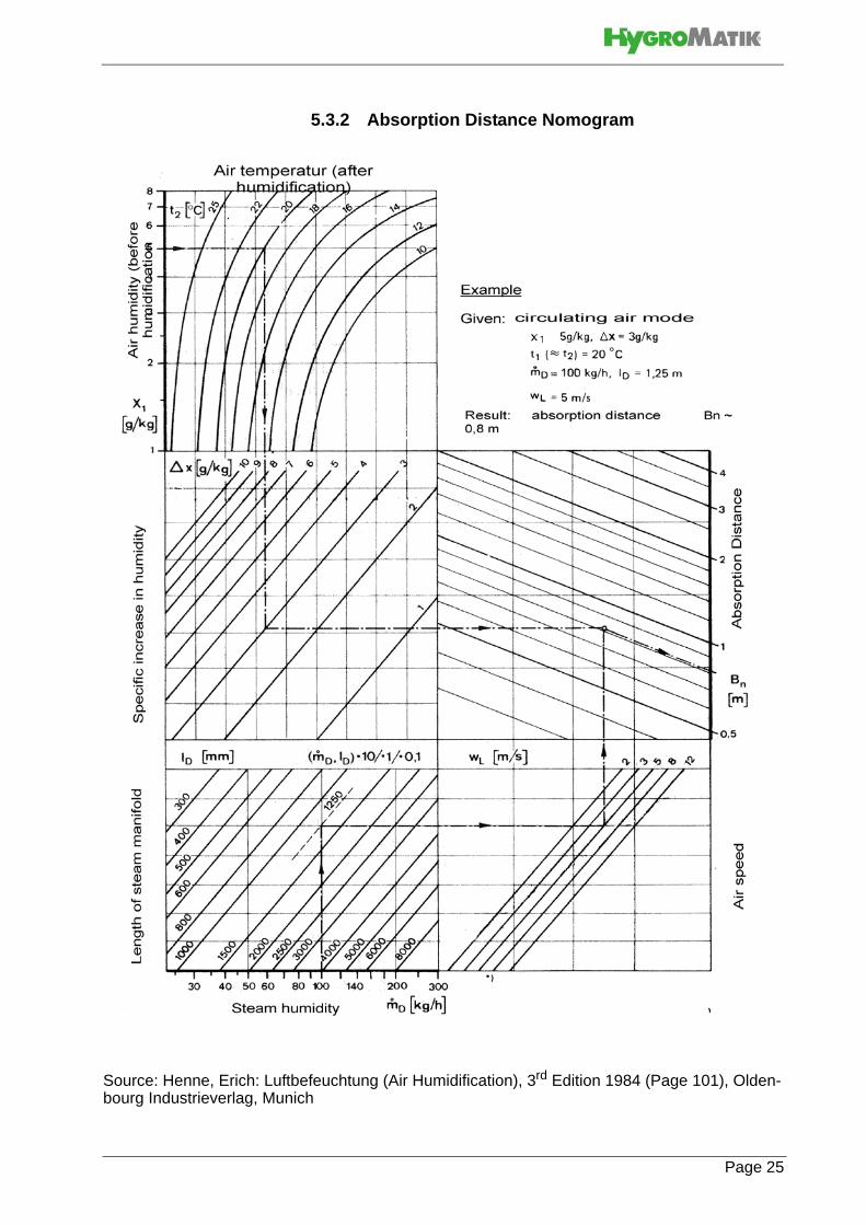
Graphically determine absorption distance BN using the absorp-tion distance nomogram (also see Section „Absorption DistanceNomogramm“). Enter the value of the parameters enumeratedabove into the respective quadrants. The resulting point of inter-section indicates the value of the desired absorption distanceBN.
Notes:
x1: _______________________________[g/kg]
t2: _______________________________[°C]
x:_______________________________[g/kg]
:_______________________________[kg/h]
wL: _______________________________[m/s]
lD: _______________________________[mm]
ir humidity before humidification
temperature after humidification
Specific increase in humidity
quantity of steam introduced
air speed t
tal length of the steam manifold
o
Dm
Page 24
Page 25
5.3.2 Absorption Distance Nomogram
Source: Henne, Erich: Luftbefeuchtung (Air Humidification), 3rd Edition 1984 (Page 101), Olden-bourg Industrieverlag, Munich

5.4 Steam Manifold
5.4.1 Notes on Installation
These notes are based on a homogeneous
Standard steam manifold installation:
An even distribution of steam manifolds ensures a uniform steam distribution.Please use the total hight of the duct!
Minimum distances in order to avoid condensation:
Lmin = 210mm: distance „ steam manifold - next steam mani-fold“
L4min = 120mm: distance „lowest steam manifold - duct bottom“
L5min = 120mm: distance „highest steam manifold - duct ceil-ing“Installations depending on special designs of air ducts
Horizontal installation ofsteam manifold
Steam Manifold
L1=L2=L3
Duct
Steam Manifold
Air flow
Air flowdirection
Page 26

Steam manifold
placement:
Horizontal installation of the steam manifolds is preferred.However, installation from below into the air duct is possible.
Air duct Positioning of steam manifolds Sample
flat Staggered vertically and laterally
Air flow
very flat By tilting the steam manifold 30 - 45°towards the air flow direction, the mini-mum upper clearance can be reducedto 70mm.
min. distances: H1[mm] H2[mm]
30° 45°
DN25 182 168 225
DN40 193 179 230
very flat duct
narrow, high Identical lenghts one on top of the other.Staggered laterally if possible.
square Identical lenghts, staggered verticallyand laterally
low, very wide
facing each other
Vertical installation of steam manifold
Page 27

• Install the steam manifold horizontal with it ensure a cleansteam out.
• Maximum allowable pressure in the air duct is 1200 Pa.For Hy05 and Hy08 the maximum allowable pressure is1000 Pa.
• On the return side, the maximum allowable negative airpressure is 500 Pa. Placement of the steam manifold onthe supply side of the air duct is preferred.
• With high-pressure air-conditioning systems, the unit'sdrain hose system must be modified depending on theover pressure. When this is the case please consultHygroMatik.
• Install the steam manifold as close as possible to thesteam humidifier in order to minimize steam loss throughcondensation.
• Shown installation and position dimensions are based onexperimental values. Special environmental conditionscould require adjustments.
• Install a water drain within the absorption distance insidethe air duct.For steam bath applications: Install the steammanifold safe from contact with people in order to preventinjuries or burns. Do not install the steam manifold near atemperature sensor or inaccurate readings may result.Airflow rates over 3m/s can possibly lead to condensatedrainage problems at the steam manifolds which mayrequire adaptation measures.
Length of steam manifold [mm]*:
* special lenght on request
l 220 400 600 900 1200 1450
DN25 x x x x x x
DN40 x x x x x x
Please note
l
installed steam manifold
Page 28

The number and size of appropriate steam manifolds, as wellthe nominal width of their respective steam and condensatehoses, are found in the tables below.
HyLine:
CompactLine:
HeaterCompact/Kit:
HeaterLine:
CompactLineKit:
* For units HL 6 - 12 and HC3-12 HygroMatik delivers one adapter DN40 / 25 (but not for SPA applications).** For units HL 36 - 45 HygroMatik delivers one t-connector for sepa-rating the steam on two steam manifolds.***Hl 60.-90 are double units and consist of Hl 30-45 units.
Type Steam Manifold Steam Hose Condensate hose
HY05-HY17 1xDN25 DN25 DN12
HY05DS - HY17DS (for SPA)
1xDN40 DN40 DN12
HY23-HY30 1xDN40 DN40 DN12
HY45-HY60 2xDN40 2xDN40 2xDN12
HY90-HY116 4xDN40 4xDN40 4xDN12
Type Steam Manifold Steam Hose Condensate Hose
C01-C06 1xDN25 DN25 DN09
C06-C17 1xDN25 DN25 DN12
C10-DS, C17DS (for SPA)
1xDN40 DN40 DN12
C22, C30 1xDN40 DN40 DN12
C45** 2xDN40 DN40 DN12
C58 2xDN40 2xDN40 2xDN12
Type Steam Manifold Steam Hose Condensate Hose
HC02/Kit 1 xDN25 DN25 DN12
HC03-12* 1xDN25 DN25 DN12
HC03-12/Kit 1xDN40 DN40 DN12
HC16-27/Kit 1xDN40 DN40 DN12
HC3-27 (for SPA) 1xDN40 DN40 DN12
Type Steam Manifold Steam Hose Condensate Hose
HL 6-12 * 1xDN25 DN25 DN12
HL 6-12(for SPA)
1xDN40 DN40 DN12
HL 18-30 1xDN40 DN40 DN12
HL 36-45 ** 2xDN40 1xDN40 1xDN12
HL 60-90 *** 2x(2xDN40) 2x(1xDN40) 2x(1xDN12)
Type Steam Manifold Steam Hose Condensate Hose
C01 Kit - C06 Kit 1x25 DN25 DN9
C10 Kit - C17 Kit 1x25 DN25 DN12
C22 Kit / C30 Kit 1x40 DN40 DN12
C45 Kit 2x40 DN40 DN12
Page 29

5.5 Steam Line
When installing the steam hose, please pay attention to the fol-lowing:
• Because of the high requirements on hose material underthe operating conditions given, it is recommended to usegenuine HygroMatik hoses only
• The steam hose diameter may not be smaller than thesteam outlet of the HygroMatik steam humidifier (do notrestrict the cross-section, otherwise back pressure willincrease)
• The steam hose must be without sags and kinks and belaid with a continuous slope of 5-10% (otherwise sags willbe formed)
• The steam hose should be as short as possible
• Run steam pipe lengths over 5m as hard piping
• The hose clamp for fixing the steam hose on the steamhose adapter should not be tightened too hard since thesteam hose adapter is made of plastic
• In the case that steam output is distributed on two steammanifolds, the Y-pieces for the steam and condensatehose should be installed near the manifolds. If the installa-tion is carried out in this way, since only one steam hose isnecessary for the main part, loss of condensate will bedecreased. In deviation of this the y-piece that is delive-red ex works with a humidifier type C45, HL36, HL45should be installed near the humidifier
• Depending on how the hose is laid, hose clips should beset at intervals of approx. 500 mm
• Allow easy access to the steam hose, so that it can beinspected laterIn case of straight lengths of severalmeters, it is recommended to lay the steam hose in tempe-rature resistant plastic pipe (40 mm dia for hose DN25; 60mm dia for hose DN40) or to use copper pipe
• Device output, steam line installation, and the duct itselfall influence pressure condition in the duct. Such, in a par-ticular situation, this could mean that optimisation of thesteam line installation will be required
• Allow for minimum bending radii: Steam hose DN25: Rmin = 200 mm Steam hose DN40: Rmin = 400 mm Steam hose DN 40: Rmin = 400 mm
Please note
Page 30

5.6 Cover Plate
HygroMatik flange plates may be used to neatly complete instal-lation of the steam humidifier in the air duct.
Two-piece flange plates are available for the DN25 and DN40steam manifolds.
flange plate DN25 E-2604260
flange plate DN40 E-2604410
Page 31

5.7 Condensate Hose
To keep condensate from accumulating in the duct, ensure thatthe condensate drains freely.
If the steam manifold is positioned higher than 500 mmabove the steam humidifier:
» Bore up the connection stub on the upper steam cylin-der part (Diameter: 8mm; for units type C01 and C06: 5mm).
» Lay the condensate hose at an approximate incline of 5-10% to the steam cylinder connection fitting, to allow the condensate to drain freely.
It is recommended to form a loop of 200 mm diameter as avapour trap provided there is enough space. Possible operatingnoises can be reduced in this manner. The loop should be filledwith water before commissioning.
If the steam manifold is positioned lower than 500 mmabove the steam humidifier:
» The condensate must be drained separately.
» To prevent steam loss, lay a loop at least 200 mm in di-ameter. The loop should be filled with water before commissioning.
» To ensure condensate drainage, place the loop (vapor trap) as far away as possible below the steam manifold connection.
» The condensate connection on the steam cylinder must be closed with a sealing cap.
» Place hose clamps at intervals of at least 500 mm, de-pending on how the hose is laid.
5.8 Types of Installation
If the steam manifold is positioned higher than 500 mmabove the steam humidifier:
» Lay the steam hose at a height of at least 400 mm above unit and then connect to the steam manifold with a constant rise or fall.
» Lay condensate hose with a slope to the steam cylin-der.
Please note
Page 32

» If enough space is available, lay a loop as a vapor trap. The steam manifold must be at least 500 mm from the loop.
If the steam manifold is positioned lower than 500 mmabove the steam humidifier:
» Lay steam hose at a height of at least 400 mm above unit and then connect to the steam manifold with a con-stant fall.
» Lay condensate hose with a loop of 200 mm diameter (vapour trap) to the drain. The distance between vapour trap and steam manifold should have at least 500mm.
» Lay the loop of condensate hose 200 mm directly above the drain. Detail x
Page 33

5.9 Steam Solenoid Valves
When humidifying a number of loads, which are to be controlledseparately, using a single steam humidifier, steam solenoidvalves can be included in the steam hoses. Valve control has toprovided by the customer.
• Install the vertical risers with flow from bottom to top
• The best position is just above the steam humidifier
Steam solenoid valve installation principle
5.10 Unit Installation Check
Improper unit handling hazard! This unit may only be broughtinto operation by qualified personnel.
Before start-up, please check proper unit installation followingthe list below:
Is the unit perpendicularly aligned in both the vertical and horizontal axis?
Have all clearances been obeyed?
Does steam hose have a slope of 5-10%?
Is condensate hose installed with a loop of min. 200 mm?
Is steam manifold positioned correctly?
Are all bolts and clamps tightened?
Page 34

6. Water Installation
Risk of scalding!Very hot water on the humidifier drain side!Have all work performed by professional staff to avoid risk ofscalding by inadequate water flow.
Risk of electrical shock!Hazardous electrical high voltage!Before starting installation work ensure yourself that the unit isnot connected to the power grid.
General rules
• Obey local public utility regulations• Verify that necessary safety measures have been taken
– in compliance with either German Technical and Sci-entific Association for Gas and Water (DVGW) guide-lines (DIN EN1717) or local regulations – to eliminate backflow of polluted water into drinking water treatment facilities. This may require the installation of a system separator and free discharge into the drainage system. Within the humidifier, a double check valve (58) is located in the water supply line. It prevents - in accor-dance with DIN EN 61770 - the backflow of water. Alter-natively, units are available that feature the DVGW-conform HyFlow system separator making further safety measures obsolete
• Use feed water without chemical additives and with a conductivity between 200 and 800 µS/cm only. Beyond conductivity levels of 800µS/cm up to a maximum of 1250µS/cm and below conductivity levels of 200µS/cm to a minimum of 125µS/cm, special adjustments are required. In this case please contact your specialist-dealer
• Supply water temperature must not exceed 40° C.• Allowable range of water pressure: 1 - 10 bar (100 x
103 to 100 x 104 pascal)• Blow-down water must be able to drain
Page 35

6.1 Operation with Softened Water
Do not use softened water unless special measures aretaken!
When feeding softened water into the HygroMatik steam humidi-fier, the aspects outlined below must be taken into account.
Softened water may cause
• unacceptably high conductivity
• the formation of salt bridges between the electrodes and the electrode leads on the inner surface of the top part of the steam cylinder
• foaming in the steam cylinder
Salt bridges cause electrical arcs. These are indicated by thepresence of black grooves in the top part of the cylinder. The cy-linder part must then be replaced to prevent further damage tothe cylinder material, as well as short circuits which trip main cir-cuit breakers.
Foam comes into contact with the maximum water level sensorelectrode and triggers a signal indicating the cylinder is filled tocapacity, even though this is false and the nominal current has
Page 36

6.2 Water Supply
Foreign material in water supply pipe may cause prematuredamage to the solenoid valve!Flush the water supply pipe before making connection to thesolenoid valve. This is of particular importance in case of anewly installed pipe.
In case of no safety device for drinking water protection accord-ing to DIN EN 1717 present in the house installation system, asystem separator at least of the CA type is mandatory. Alterna-tively, a humidifier special model featuring the HyFlow provisionmay be used.
» Install a shut-off valve (SV) in the supply line.» Install a water filter (WF) if necessary.
Shut-off valve (SV) and water filter (WF) are not supplied withthe unitHygroMatik provides a water hose (56) with a cap nut atboth ends which can be used for water installation.
» Check presence of solenoid valve strainer (29) and insert strainer, if not yet in place.
» Screw one of the cap nuts with its inner seal ring onto the connection stud protruding from the humidifier hou-sing and tighten.
Please note
Please note
Page 37

» .
Do not overtighten the cap nut!Excessive tightening will destroy the fitting.
» Screw the other hose end cap nut with its inner seal on a customer-provided water tap (cup nut internal thread is ¾“).
6.3 Water discharge
Risk of scalding!During blow down up to 0.3 l/sec are being drained with a tem-perature of about 95° C.Wastewater must drain freely and pressureless.Avoid contact in order not to burn skin.
With the optional wastewater cooling system HyCool, HygroMa-tik offers an option for limiting the wastewater temperature of thesteam humidifier in order to protect thermosensitive wastewaterpipe lines. By blending with cold water during the blow-down andrinse process, it is ensured that the wastewater always has atemperature below 60°C.
Humidifier installation location and wastewater discharge mustbe on the same pressure level.
Install water discharge as follows (use of a flexible water drain-hose is recommended:
» Do not buckle the drain hose.
» Install discharge line and drain pipe made from tempe-rature resistant material (up to 95° C).
» Run a 1 1/4 " drain hose of 250 - 1000 mm length into a pressure-free outlet and according to DIN EN 1717. The hose must be guided sideways of the humidifier to prevent ascending vapor from condensating on the humidifier`s housing.
» Fit water drain hose over the pump drain hose and fasten to the housing drain connection.
Please note
Please note
Page 38

Two grounding clips are attached to the inner surface of thehousing drain stub. The end of the pump drain hose is pushedinto one of these clips. The overflow hose of the HyFlow systemseparator - if present - is pushed into the other clip. During blow-down, the grounding clip is in direct contact with water andshunts potential residual electric currents away from the hous-ing.
There is a 3mm-wide crack between the pump drain hose jacketand the inner surface of the housing drain connection. If watercollects on the base plate, it will flow through this crack into thefloor drain.
Grounding clips
Drain hose frompump
Drain stub onhousing
Page 39

6.4 HyFlow Provision (Special Model)As special models, HygroMatik humidifiers are available featu-ring the HyFlow system separator made of plastic (DVGW CERTAS-0625CP0094 for HyLine and DVWG CERT AS-0625CP0095for C-Line).
The functions of the HyFlow cup are:
• cylinder filling
• separation of feed water supply and cylinder water , accor-ding to DIN EN 1717
• overflow protection in case of cylinder intake blocking
Cylinder filling
When the solenoid valve opens, water flows through the HyFlowcup into the cylinder base. The cylinder is filled by the staticpressure of the water column.
Overflow protection
If the water level in the HyFlow cup gets too high, water flowsover a partition panel into the draining system. In the unlikelycase of both the cylinder intake and the drain being blocked, thewater flows out through the overflow breakout and leaves thedevice through the wastewater hose. Contamination of the drink-ing water is thus excluded.
Ø 10 Overflow/drain to wastewater system
Ø 14 Drain to cylinder base
Ø 8 Filling from
solenoid valve
Overflow in case ofblocking
Page 40

6.5 Water Installation Check
Go down the following water installation checklist:
Are all screws and clamps properly tightened?
Is the water supply pipe flushed?
Was the water installation correctly installed?
Can the blow-down water drain freely?
Was the water discharge correctly installed?
Is there no leakage from the water supply pipe and water discharge?
Page 41

7. Electrical Connection
Risk of electrical shock!Hazardous high voltage!All work related to electrical installation to be performed byauthorized personnel only (electricians or professionals withequivalent training).
The customer is responsible for checking qualifications.
Do not connect the steam humidifier to the live power gridbefore all installation work has been completed!
General installation rules
• All wiring must confirm to CEC, NEC and local electrical codes.
• Install the electrical connections according to the wiring diagram.
• Οnly a permanent connection to permanent wiring is allo-wable (UL998 CSA Std 222.2).
• Electric connector cables to be laid professionally
Take care of ESD protection!The electronic components of the humidifier control are verysensitive to electrostatic discharges. In order to protect thesecomponents during any type of installation, steps must be takento guard against damage from electrostatic discharge.
7.1 Electrical Installation
» Fuses must have a contact gap of at least 3mm per pole.
» Install a separate main connection for each steam cylin-der, complete with main contactor, main switch, etc.
» Connect potential equalization to the outer ground bolt.
» Observe VDE 0100 when selecting wire cross-sections.» Verify that all terminals have been tightened
Please note
Page 42

Power supply connections
Make connections as shown in the table:
Other voltages are available on request. Fusing
We recommend employing medium blow main fuses (applicable only to the grid voltages indicated in the table below). The tables below show power usage and the circuit protection required for the various HygroMatik humidifier models.When using fault cur-rent circuit breakers pls. use a dedicated current circuit breaker for the humidifier.
HyLine:
CompactLine:
Type Standard Main Power Supply
HY05 - HY45 1 x 400V/3Phase/N
HY60 - HY116 2 x 400V/3Phase/N
C01, C02 1 x 230/1Phase/N
C06 - C58 1 x 400V/3Phase/N
MS5, MS10 1 x 400V/3Phase/N
MS5 1 x 230/1Phase/N
C01Kit, C02Kit 1 x 230V/1Phase
C06Kit - C45Kit 1 x 400V/3Phase/N
Type Power Usage Circuit Protection*)
HY05 5,4 A 3 x 6A
HY08 8,7 A 3 x 10A
HY13 14,1 A 3 x 16 A
HY17 18,4 A 3 x 20 A
HY23 24,9 A 3 x 35 A
HY30 32,5 A 3 x 35 A
HY45 48,8 A 3 x 63 A
HY60 2 x 32,5 A 6 x 35 A
HY90 2 x 48,8 A 6 x 63 A
HY116 2 x 62,8 A 6 x 63 A
Type Power Usage Circuit Protection*)
C01 3,3A 1 x 6A
C02 6,5A 1 x 10A
C06 6,5 A 3 x 10 A
C10 10,8 A 3 x 16 A
C17 18,4 A 3 x 20 A
C22 23,8 3 x 35 A
C30 32,5 A 3 x 35 A
C45 48,8 A 3 x 63 A
C58 62,8 A 3 x 63 A
Page 43

MiniSteam:
CompactLine KIT:
*) After full blow down, power input is 1.3 times higher than innormal operation. The circuit protection recommended takes thisinto account. However, should problems arise when usingexpulsion fuses close to their specific limit, it is recommended toemploy fuses with a higher range.
Type Power Usage Circuit Protection*)
MS5, 230V/1/N 15,7 A 1 x 16 A
MS5, 400V/3/N 5,4 A 3 x 6 A
MS10, 400V/3/N 10,8 A 3 x 16 A
Type Power Usage Circuit Protection*)
C01KIT, 230V/1/N 3,3 A 1 x 6 A
C02KIT, 230V/1/N 6,5 A 1 x 10 A
C06KIT, 400V/3/N 6,5 A 3 x 10 A
C10KIT, 400V/3/N 10,8 A 3 x 16 A
C17 KIT, 400V/3/N 18,4 A 3 x 25 A
C30KIT, 400V/3/N 32,5 A 3 x 35 A
C45KIT, 400V/3/N 48,8 A 3 x 63 A
Please note
Page 44

7.2 Cable Connections
The table below shows the number and size of the cable con-nections provided in the various electrode steam humidifiers:
Characteristics of metric cable connections:
Unit type Connection M16
Connection M25
Connection M32
HY05, HY08 4 3 -
HY13, HY17, HY23, HY30, Hy45
4 2 1
HY60, HY90, HY116
- 4 2
C01, C02 3 2 -
C6 3 2 -
C10 3 3 -
C17, C22, C30 4 3 -
C45, C58 4 2 1
MS05, MS10 - 2 -
Thread across-flats dimensions [mm]
for cable diame-ter [mm]
M16x1,5 19 4,5 - 10
M25x1,5 30 9 - 17
M32x1,5 36 11 - 21
Page 45

Page 46
7.3 Fan Unit
» Connect fan unit according to the wiring diagram.
The fan unit operates in parallel with the humidifier.
Terminals 37 and 38 are only installed if the option „fan unit“ isordered.
Please note

Page 47
7.4 Safety Interlock
Install contact interlocks, i.e. a max. hygrostat, vane relay, pres-sure controllers, air interlock devices, etc. in series across termi-nals 1 and 2.
Use max.-hygrostat for protection!A max-hygrostat should be installed in the safety interlock. Themax-hygrostat acts as a safety device in case the humidity sen-sor malfunctions.
Contacts across terminals 1 and 2 must be potential-freeand properly rated!Rating must comply with the control voltage in use (24 VAC or208-240 VAC, see technical data on the unit‘s name plate).
7.5 Wiring Diagram
Please remove the wiring diagram from the technical manualsupplied with the control used with your humidifier. Every steamhumidifier comes with one technical manual for the unit and onefor the control.
7.6 Electrical Installation ChecklistPerform electrical installation checks in compliance with cus-tomer site requirements and public power utility regulations:
Is the power grid voltage compatible with the voltage on the name plate?
Have all electrical connections been made according to the terminal connection diagram?
Have all electrical cable and plug connections been properly tightened?
Are all electrical socket connections secure?
Is the unit grounded?
On the succesful completion of all of the checks the unit is readyfor switching on.
Ensure proper grounding of unit cover!The unit cover must be in place and the lock must be engaged(applies only to humidifier types HyLine and MiniSteam).
Please note

8. Commissioning
Risk of operating error!Start-up of the unit is restricted to expert staff only (electriciansor expert personnel with equivalent training).
Step 1: Check of mechanical integrity
» Check cylinder seating.
» Check steam and condensate hose clamps.
Step 2: Check of electrical wire connections
» Check that all electrical wire connections, including heater element wire connections, are tight and secure.
Step 3: Switching on the steam humidifier
» Switch on main breaker.
» Open water supply stopcock (operating pressure should be 1bar min., 10bar max./14.5 psi min., 145 psi max.).
» Switch on unit by setting control switch to “I”.
» For initial operation check, set control unit in a way that a humidity demand results.
Step 4: The unit performs a self-test
• If the control includes a display, the message “self-test“ is displayed.
For the next steps, control must be set in a way that permanentsteam demand is requested.
Please note
Page 48

Step 5: Normal operation starts
• the water solenoid valve opens and feeds water into the steam cylinder
• Initiation of steam production may take up to 20 min-utes
» Let all electrically-driven operations run to completion. As soon as the solenoid valve begins replenishing the water periodically, the steam humidifier operates at steady nominal output and the cold start sequence is complete.
Step 6: Monitor unit for leaks
» Let unit operate for 15 to 30 minutes.
» If leaks appear, switch off the unit.
Risk of electrical shock!Hazardous electrical high voltage!Follow safety instructions for work on live components.
Step 7: Repair leaks
» Repair leaks.
» Check again.
Page 49
9. Maintenance
The HygroMatik steam humidifier is easy to maintain. However,inadequate or improper maintenance can lead to operationalmalfunctions. Perform regular maintenance to give your unit along life span.
The unit is only to be serviced by qualified personnel!
All safety instructions must be observed.
After maintenance work, have qualified personnel check that theunit is operating safely.
Risk of electrical shock by hazardous voltage!
Switch off the unit before maintenance and protect againstrestart.
.
Take care of ESD protection!The electronic components of the humidifier control are verysensitive to electrostatic discharges. In order to protect thesecomponents during maintenance, steps must be taken to guardagainst damage from electrostatic discharge.
The steam humidifier's performance and maintenance intervalsprimarily depend on water quality (carbonate hardness, conduc-tivity) and the quantity of steam produced since the last mainte-nance. Abnormal water quality can shorten or lengthenmaintenance intervals. Ongoing maintenance intervals can beestimated based on the amount and type of residue found in thesteam cylinder.
Page 50

Cylinder maintenance is required the latest if the following condi-tions apply:
9.1 Maintenance Work
Mineral deposits precipitate and crystallize very differently in dif-ferent types of water, even when two types have the same con-ductivity and hardness levels (the various constituents in thewater interact differently).
Instructions on maintenance and cleaning intervals, or on elec-trode service life, are based entirely on empirical data. Seals arewearing parts. As such, checking and replacing seals if requiredis mandatory in the scope of periodical maintentance.
In most cases, the conductivity levels given in the "Directions forUse" section of this manual may be considered as typical val-ues. Individual parameter settings as part of the control soft-ware may be necessary.
In extreme cases, water pretreatment may be necessary (soft-ening by dilution to approx. 4 - 8 °dH; decarbonization/partialdesalination to achieve target reductions in carbonate hard-ness). For any questions with regard to water treatment systemspls. contact HygroMatik.
Control Indicator
Basic Maintenance message: red and green LEDs areblinking: Unit has switched itself off automatically.
Comfort
Comfort Plus
Maintenance message on display (red and greenLED are blinking). Unit has switched itself off auto-matically.
Cycle Maintenance Work
4 Weeks after initial operation
(with normal water quality)
Visual inspection of electrical andmechanical connections
Remove mineral deposits from steam cyl-inder, water drain hose and blow-downpump
Check electrodes for erosion
Semiannually(with normal
water quality and "normal" opera-tion = 8h/day)
Visual inspection of electrical andmechanical connections
Remove mineral deposits from steam cyl-inder, water drain hose and blow-downpump.
Check electrodes for erosion
Page 51

9.2 Access to Electrical Enclosure
Risk of electrical shock by hazardous voltage!
Make sure the unit is switched off before installing or removingthe display panel.
» Remove cover from humidifier (B) and lift display panel (A) off guiding.
» Turn display panel by 90 degrees (see fig. on the left) and attach display panel to the humidifier cabinet by placing the two guide pins in the corresponding slots.
» The basic PCB (C) is now accessable.
9.3 Removing and Cleaning the Steam Cylinder
Risk of skin burning!Hot steam cylinder during operation and for some time after-wards.Drain steam cylinder before any maintenance work is com-menced.Switch off unit and protect against restart.After that, wait approx. 10 mins before starting maintenancework.Check steam cylinder temperature by cautious approximationwith hand (do not touch!)
After beeing in use for a long time some mechanical cylindershrinkage may occur. While this has no effect on the devicefunction, it may cause a problem when only one half of the cylin-der is exchanged. Such, it is generally advisable to exchangethe complete cylinder.
Please note
Page 52

Risk of injuries to the eyes!Cylinder clips may jump off due to pretension.Wear proper PPE (Personal Protection Equipment)!
Risk of cut injuries!Both the clips that fix the steam cylinder halves and the elec-trodes have sharp edges and angles.Wear proper PPE (Personal Protection Equipment)!
Risk of electrical shock by hazardous voltage!Disconnect the appliance from power supply before removingcover.
on/off switchin position II
After cylinder draining switch off unit
Disconnect unit frompower grid and secure against reconnection
Open unit
Page 53

Remove stopper Verify safe isolation
Disconnect unit from water supply
Remove steamhose from adapterCheck cylinder temperature
Completely drain the cylinder
Push clip on adapteroutside cabine Lift steam cylinder out of base
Page 54

» Check the inside of the top part of steam cylinder for crust build-up and possible salt bridges (black grooves between the electrode leads). If present, wash away completely.
If electrical arcs have burned deep grooves into the material, thetop part of the cylinder (better: the complete cylinder, s. above)must be replaced.
» Clean the sensor electrode until it is metallically bright.
Unplug electrodes /sensor electrode
Remove flange clamps
Remove used O-ring
Clean strainer
Clean cylinder inside. Do not use acids or other chemicals
Please note
Page 55
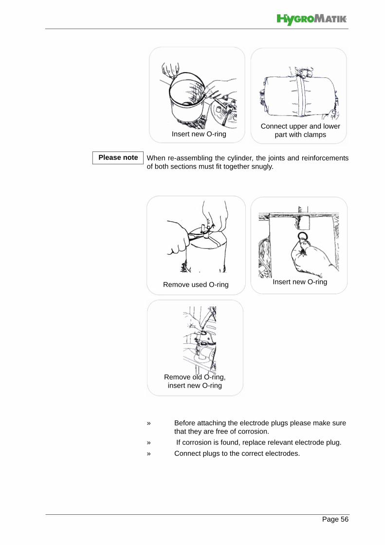
When re-assembling the cylinder, the joints and reinforcementsof both sections must fit together snugly.
» Before attaching the electrode plugs please make sure that they are free of corrosion.
» If corrosion is found, replace relevant electrode plug.
» Connect plugs to the correct electrodes.
Insert new O-ringConnect upper and lower
part with clamps
Please note
Remove used O-ring Insert new O-ring
Remove old O-ring,insert new O-ring
Page 56

Ensure proper plug seating on electrode!
The plug must be pressed down onto the electrode as far as itwill go.
Wiring color corresponds with the color of the knurled nut.
The condensate connection must be showing towards the fronton the left hand side.
Please note
Please note
Place cylinder vertically into cylinder base
Connect plug to level sensor / electrodes
Hold adapter in place with clip
Reconnect to power grid
Attach adapter to steam outlet
Open water supply
Page 57

Risk of electrical shock by hazardous high voltage!
Obey safety instructions for work on live equipment.
» switch on unit and monitor for leakage during 15-30 minutes of operating.
» In case of leakage switch of unit and redeem lea-kage(s).
» Monitor again; repeat procedure until no more leakages are detected.
Ensure proper unit grounding!In order for the unit cover to besafely grounded, the cover must be fully closed and the lockmust be engaged (this refers only to humidifier types HyLine andMiniSteam).
Check for leakages Close cabinet
Page 58

9.4 Electrode wear
Electrode wear depends on:
• feed water composition and conductivity
• the quantity of steam produced
Monitor electrode lengths!
When the electrodes are less than 1/3 to 1/2 of their originallength, they should be replaced . At the latest, the replacementshould be carried out when a maintenance message is dis-played asking for replacement. This maintenance message willappear after one hour of operation at maximum water level. Thehumidifier operation will then stop.
9.4.1 Original Electrode Lengths
Initial lengths of HygroMatik large area stainless-steel electrodesare as indicated in the tables below.
HyLine:
CompactLine:
Type HY05-HY08 HY13-HY60 HY90-HY116
Length [mm]
[inch]
155
6.1
235
9.25
300
11.8
Type C6 C10 C17-45 C58
Length [mm]
[inch]
125
4.9
155
6.1
235
9.25
300
11.8
Page 59
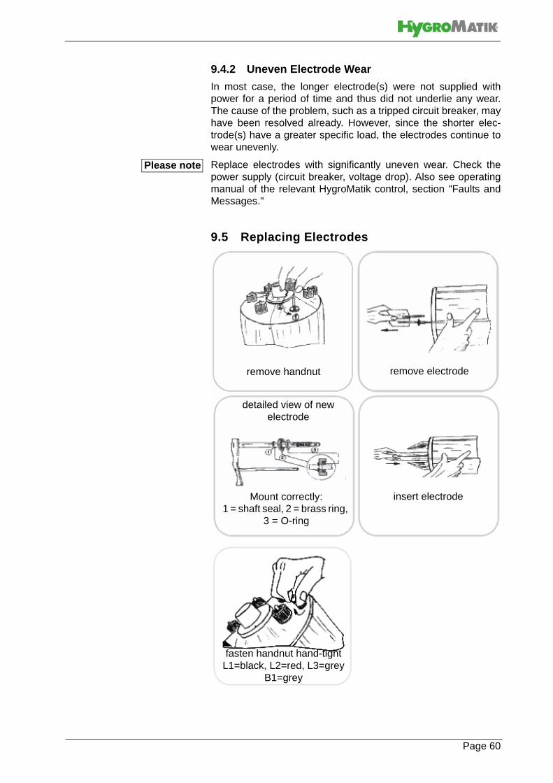
9.4.2 Uneven Electrode Wear
In most case, the longer electrode(s) were not supplied withpower for a period of time and thus did not underlie any wear.The cause of the problem, such as a tripped circuit breaker, mayhave been resolved already. However, since the shorter elec-trode(s) have a greater specific load, the electrodes continue towear unevenly.
Replace electrodes with significantly uneven wear. Check thepower supply (circuit breaker, voltage drop). Also see operatingmanual of the relevant HygroMatik control, section "Faults andMessages."
9.5 Replacing Electrodes
Please note
remove handnut remove electrode
detailed view of new electrode
Mount correctly:1 = shaft seal, 2 = brass ring,
3 = O-ring
insert electrode
fasten handnut hand-tightL1=black, L2=red, L3=grey
B1=grey
Page 60

» Remove and open cylinder, as described in Section 8.3 "Removing and Cleaning Steam Cylinder."
» Loosen knurled nuts (5) and remove electrodes (48).
» Install new electrodes and hand tighten the nuts.
» Use solvent-free, HygroMatik-quality o-rings (for flange, cylinder base and steam hose adapter).
» Assemble steam cylinder and place it into cylinder
» Connect plugs (4) directly to the electrodes (48) (with gray, red and black knurled nuts). It is not necessary to detach the knurled nuts!
Ensure proper plug seating on electrode!
The plug must be pressed down onto the electrode as far as itwill go.
Connect plugs to the correct electrodes. Pay attention to thecolor of the associated knurled nuts.
» Attach plug (8) to the sensor electrode. (Knurled nut (9) - gray)
» Switch breaker back on.
» Switch on the unit and check for leaks after 15-30 mi-nutes of operation.
» If leakage occurs, switch off power supply and eliminate leakage following safety instructions for work on live components.
Water conductivity is too high or water is not decanted oftenlyenough if the following phenomina are observed:
• electrodes must be frequently replaced,
• black slime collects inside the cylinder, or
• there is "lightning" in the cylinder.
In all of these cases please contact HygroMatik.
9.6 Cleaning the Blow- down pump
» Remove cylinder
» Detach e-cable from pump.
» Detach adapter (30) from pump.
» Unscrew screws (44) and remove pump from base.
» Open pump (bayonet lock).
» Remove residues from drain hoses and pump (if necc-essary replace o-ring (33) or housing (34) if these com-ponents are no longer in excellent condition).
» Reassemble pump.
Please note
Please note
Page 61

» Moisten o-ring (31) and insert into cylinder base hori-zontal stub.
» Push pump into cylinder base and mount tightly with screws (44).
» Moisten o-ring (31) and insert in adapter (30).
» Slide adapter (30) over stub on pump side.
» Connect e-cable to pump.
» Install cylinder.
» Switch on unit and check for leaks during operation.
Hazardous voltage! Risk of electrical shock!
Follow safety instructions for work on live components.
» In case of leakage turn off power supply and secure against being switched on again.
» Redeem leakage.
» Check again.
Page 62

9.7 Cleaning the Water Inlet Solenoid Valve
Removal
» Shut off water supply and loosen water installation hose connection.
» Remove cylinder.
» Remove connecting hose (21) from cylinder base.
» Detach electrical cable from solenoid valve.
» Unscrew solenoid valve mounting screws and remove solenoid valve from housing.
» Clean solenoid valve intake area
» Remove mesh filter (29) from solenoid valve and clean. Replace if required.
Installation
» Insert fine mesh filter.
» Reinsert solenoid valve with seal in unit housing open-ing and bolt down.
» Screw on water installation hose.
» Connect electrical cable to solenoid valve.
» Attach connecting hose (21) to cylinder base.
» Install cylinder.
» Turn on water tap.
» Switch on unit and check for leaks during operation.
Hazardous voltage! Risk of electrical shock!
Follow safety instructions for work on live components.
» In case of leakage turn off power supply and secure against being switched on again.
» Eliminate leakage.
» Check again.
Page 63

9.8 Cleaning the Water Inlet Solenoid Valve andHyFlow System Separator (special modelsonly)
Removal
» Shut off water supply and open water installation hose connection.
» Remove cylinder.
» Remove grounding sleeve (62) from solenoid valve (63). To do so, push the collet into the John-Guest con-nection fitting and pull out the grounding sleeve with the HyFlow connecting hose attached.
» Remove connecting hose from HyFlow to cylinder base.
» Detach electrical cable from solenoid valve (63).
» Remove solenoid valve and HyFlow mounting screws.
» Remove solenoid valve and HyFlow from the housing.
» Clean inlet section of solenoid valve.
» Open and clean HyFlow.
Installation
» Reinsert solenoid valve with seal in the unit housing opening and bolt down.
» Screw on water supply hose.
» Connect electrical cable to the solenoid valve.
» Attach HyFlow with screw.
» Attach connecting hose (21) to the base. Squeeze the John Guest connections firmly.
» Install steam cylinder.
» Turn on water tap.
» Switch on the unit and check for leaks during operation.
Hazardous voltage! Risk of electrical shock!
Follow safety instructions for work on live components.
» In case of leakage turn off power supply and secure against being switched on again.
» Eliminate leakage(s).
» Check again.
Page 64

9.9 Checking Cable Connections and ElectrodeCables
» Make sure that no cable and plug connections are loose.
Ensure proper plug seating on electrode!
The plug must be pressed down onto the electrode as far as itwill go. Loose cable connections cause excessive contactresistance and overheating of contact surfaces.
» Check electrode plug isolation, replace plugs as needed.
Electrode plugs wear out when removed and reinstalled for sev-eral times. Replace plugs when required.
9.10 Checking Hoses
Since steam and condensate hoses are also subject to wearthey have to be checked regularly.
9.11 Checking Operation
Start up the unit and operate for a few minutes at maximum out-put if possible.
» Check safety devices.
» Check hose connections for possible leaks.
9.12 DismantlingWhen end-of-life, de-installation of the steam humidifier for dis-mantling (demolish or scrap) has to follow the installation proce-dures in reverse order.
Risk of electrical shock!Hazardous electrical high voltage!Electrical dismantling must only be performed by certified expertstaff (electricians or expert personnel with equivalent training).
With regard to disposal, pay special attention to the safetyinstructions provided in section 2 of this manual.
Please note
Please note
Page 65

Page 66
10. EC-Declaration of Conformity

11. Spare Parts
* HY
05
H
Y08
HY
13
H
Y17
HY
23
HY
30
HY
45
HY
60
HY
90
HY
116
Articel No. Description
E-1702042 Lock for cover
Steam generation
16 1 B-3204031 Steam cylinder CY8 compl. with electrodes and hand nuts **16 1 B-2204231 Steam cylinder CY8 DN40 compl. with electrodes and hand nuts **,
for SPA applications since 04.2010
16 1 B-2204101 Steam cylinder CY17 DN 25 compl. with electrodes and hand nuts **
16 1 B-2204103 Steam cylinder CY17 DN 40 compl. with electrodes and hand nuts **, for SPA applications since 04.2010
16 1 B-2204111 Steam cylinder CY17 DN 40 compl. with electrodes and hand nuts **
16 1 2 B-2204105 Steam cylinder CY30 compl. with electrodes and hand nuts **16 1 2 2 B-2204109 Steam cylinder CY45 compl. with electrodes and hand nuts **17 1 E-3216010 O-ring seal for cylinder flange CY8, transparent cylinder17 1 1 E-2206050 O-ring seal for cylinder flange CY17, transparent cylinder
17 1 2 E-2206051 O-ring seal for cylinder flange CY30, transparent cylinder
17 1 2 2 E-2207011 O-ring seal for cylinder flange CY45, transparent cylinder
35 1 E-3216011 O-ring seal for cylinder base35 1 1 1 1 2 2 2 E-2204022 O-ring seal for cylinder base48 1 B-3204019 Electrodes compl. with hand nuts (M6), set=3pc. for CY848 1 B-2204081 Electrodes compl. with hand nuts (M8), set=3pc. for CY1748 1 B-2204083 Electrodes compl. with hand nuts (M8), set=6pc. for CY17 DN4048 1 2 B-2204095 Electrodes compl. with hand nuts (M8), set=6pc. for CY30 DN4048 1 2 2 B-2204085 Electrodes compl. with hand nuts (M10), set=6pc. for CY45 DN4010 1 B-3204027 Sensor electrode compl. with hand nut10 1 1 1 1 2 2 2 B-2204075 Sensor electrode compl. with hand nut10 1 1 1 1 1 2 2 2 E-3216025 Plug-in contact with isolating hose for sensorelectrode4 3 E-3216024 Plug-in contact with isolating hose for steam generating electrodes4 3 6 6 12 B-2206065 Plug-in contact with isolating hose for steam generating electrodes4 6 12 12 E-2207016 Plug-in contact with isolating hose for steam generating electrodes
18 12 18 18 24 24 48 48 48 E-3216022 Clamp for flange of transparent cylinder37 1 E-3220000 Cylinder base DN20/25/15/1237 1 1 1 1 2 2 2 E-2206086 Cylinder base DN40/25i/15/12
1 B-3216023 Mounting set for Cylinder base1 1 1 1 2 2 2 B-2214023 Mounting set for Cylinder base
1 1 E-3221002 Adapter for steam hose DN25, CY81 1 E-3221008 Adapter for steam hose DN40, CY8, for SPA applications since
04.2010
1 1 E-2209000 Adapter for steam hose DN25, CY171 1 E-2209004 Adapter for steam hose DN40, CY17, for SPA applications since
04.2010
1 1 E-2209004 Adapter for steam hose DN40, CY171 1 2 E-2209006 Adapter for steam hose DN40, CY 301 2 4 4 E-2209008 Adapter for steam hose DN40, CY 45
Page 67

* HY
05
H
Y08
HY
13
H
Y17
HY
23
HY
30
HY
45
HY
60
HY
90
HY
116
Articel No. Description
1 1 E-2209014 Adapter steam outlet DN40/252 1 1 E-3221004 Clip for adapter DN252 1 1 2 2 4 4 E-2209002 Clip for adapter DN403 1 1 E-3221006 O-ring for adapter DN253 1 1 E-2204022 O-ring for adapter DN40, for SPA applications since 04.20103 1 1 2 2 2 2 E-2204022 O-ring for adapter DN40
1 B-3216073 O-ring set CY8 (Pos. 3, 17, 35)1 B-3216099 O-ring set CY8 DN40 (Pos. 3, 17, 35), for SPA applications since
04.2010
1 B-2207021 O-ring set CY17 DN25 (Pos. 3, 17, 35)1 B-2207023 O-ring set CY17 DN40 (Pos. 3, 17, 35), for SPA applications since
04.2010
1 B-2207023 O-ring set CY17 DN40 (Pos. 3, 17, 35)1 2 B-2207025 O-ring set CY30 (Pos. 3, 17, 35)
1 2 2 B-2207027 O-ring set CY45 (Pos. 3, 17, 35)
Water feed21 0,9 1,6 1,6 1,6 1,9 1,6 1,9 1,9 E-2604002 Connecting hose solenoid valve - cylinder base, per m
25 1 B-2304021 Solenoid valve, servo controlled, straight type, 0,2-10bar, 2,5l/min.(at 4 bar)
25 1 1 1 1 2 2 2 B-2304023 Solenoid valve, servo controlled, straight type, 0,2-10bar, 3,5l/min. (at 4 bar)
1 1 1 1 1 2 2 2 E-2304036 Sealing for solenoid valve/unit
56 1 1 1 1 1 2 2 2 B-2304031 Hose for water connection, 3/4" cap nuts on both sides, seal included
1 E-3320400 Flow rate controller 2,5 l/min, for Pos. 25
1 1 1 1 2 2 2 E-2321100 Flow rate controller 3,5l /min, for Pos. 25
1 B-2304055 Double solenoid valve for Super flush applications, 2.5l/min (at 4bar)
1 1 1 1 2 2 2 B-2304057 Double solenoid valve for Super flush applications, 3.5l/min (at 4bar)
29 1 1 1 1 1 2 2 2 E-2304024 Fine filter in the inlet fitting of solenoid valve
38 0,4 0,7 0,7 0,7 0,8 0,7 0,8 0,8 E-2604004 Hose for manual water drain, per m
20 1 1 1 1 1 1 1 1 E-2604066 Stopper, conical, lock for hose
22 4 4 4 4 4 8 8 8 E-2304015 Hose clamp 10-16mm
24 0,07 0,07 0,07 0,07 0,07 0,07 0,07 0,07 E-2604002 Connecting hose solenoid valve - bush for earthing23 1 1 1 1 1 2 2 2 E-2304080 Bush for earthing
58 1 1 1 1 1 2 2 2 E-2604094 double check valve
64 1 1 1 1 1 2 2 2 B-3320403 HyFlow with air-vent
60 0,4 0,5 0,5 0,6 0,6 0,6 0,6 0,6 E-7600186 Connecting hose: bush for earthing-HyFlow
61 1 1 1 1 1 2 2 2 E-7600094 Connecting piece, straight
62 1 1 1 1 1 2 2 2 E-2304078 Bush for earthing (HyFlow)
63 1 E-2304064 Solenoid valve, (HyFlow), servo controlled, straight type, 0,2-10bar, 2,3l/min. (at 10bar), John-Guest connection 8mm
63 1 1 1 1 2 2 2 E-2304064 Solenoid valve, (HyFlow) servo controlled, straight type, 0,2-10bar, 3,4l/min. (at 10bar), John-Guest connection 8mm
65 0,4 0,6 0,6 0,7 0,8 0,7 0,8 0,8 E-2604004 Connecting hose HyFlow-cylinder base
66 0,4 0,6 0,6 0,7 0,8 0,7 0,8 0,8 E-7600224 Connecting hose HyFlow-drain
67 2 2 2 2 2 4 4 4 E-8501064 Hose clamp 12-20mm
Page 68

* HY
05
H
Y08
HY
13
H
Y17
HY
23
HY
30
HY
45
HY
60
HY
90
HY
116
Articel No. Description
Water drain
1 B-3401017 Drain-hose-system (Pos. 6, 14, 15, 30, 31)
1 1 B-3401019 Drain-hose-system (Pos. 6, 14, 15, 30, 31)
1 2 B-3401013 Drain-hose-system (Pos. 6, 14, 15, 30, 31)
1 2 2 B-3401021 Drain-hose-system (Pos. 6, 14, 15, 30, 31)
31 1 1 1 1 1 2 2 2 E-3220005 O-ring for pump-adapter31 1 1 1 1 1 2 2 2 E-3220005 O-ring for cylinder base -pump
33 1 1 1 1 1 1 1 E-2404024 O-ring for drain pump (cover-motor)32 1 1 1 1 1 2 2 2 B-2404027 Drain pump without mounting set
1 1 1 1 1 2 2 2 Mounting set for drain pump (pos. 42-44)6 1 1 1 1 1 2 2 2 E-2425004 Elbow with vent pipe
57 1 1 1 1 1 2 2 2 E-2420423 Drain hose 1 1/4"
39 1 1 1 1 1 2 2 2 E-8501064 Hose clamp 12-20mm
38 0,5 0,7 0,7 0,7 0,8 2x0,72x0,8 0,8 E-2604004 Manual drain hose
Control
universal
1 E-2501005 Main contactor 16 A, 230 V
1 B-2507041 Main contactor 20 A, 230 V
1 1 2 B-2507061 Main contactor 35 A, 230 V
2 B-2507071 Main contactor 50 A, 230 V
1 2 B-2507081 Main contactor 65 A, 230 V
1 1 1 1 1 2 2 2 E-2505206 Control fuse (fast acting) 1,6 A, 5x20 mm
4 1 B-3526019 Connecting cables for electrodes with plug-in contact, set=3pc
4 1 B-2524201 Connecting cables for electrodes with plug-in contact, set=3pc
4 1 B-2524205 Connecting cables for electrodes with plug-in contact, set=6pc
4 1 B-2524209 Connecting cables for electrodes with plug-in contact, set=6pc
4 1 B-2524213 Connecting cables for electrodes with plug-in contact, set=6pc
4 2 B-2524217 Connecting cables for electrodes with plug.,set=6pc
4 2 2 B-2524225 Connecting cables for electrodes with plug., set=6pc
8 1 1 1 B-2525051 Connecting cable sensor electrode with plug
8 1 1 1B-2525053 Connecting cable sensor electrode with plug (HY 60 = for right
cylinder)
8 1B-2525057 Connecting cable sensor electrode with plug (HY60 = for left
cylinder)
8 1 1B-2525055 Connecting cable sensor electrode with plug (HY90/HY116 = for
right cylinder)
8 1 1B-2525059 Connecting cable sensor electrode with plug (HY90/HY116 = for left
cylinder)
Steam generation with electrical supply higher than 500V
1 1 E-2206054 O-ring CY17, silicone, for cylinder flange
1 2 E-2206056 O-ring CY30, silicone, for cylinderflange
1 2 2 E-2207014 O-ring CY45, silicone, for cylinderflange
1 B-2208007 Cylinder star CY17/3
1 B-2208013 Cylinder star CY17/6
1 2 B-2208009 Cylinder star CY 30
1 2 2 B-2208011 Cylinder star CY 45
2,5 5 8 16 E-9000110 Cable H07V-K2,5 [m] for electrode connecting cable
3 6 6 12 B-2206065 Plug-in contact for electrode 35A
8 16 16 E-9000132 Cable H07V-K6,0 [m] for electrode connecting cable
6 12 12 E-2207016 Plug-in contact for electrode 63A
Page 69

* HY
05
H
Y08
HY
13
H
Y17
HY
23
HY
30
HY
45
HY
60
HY
90
HY
116
Articel No. Description
Control, electrical supply higher than 500V1 1 1 1 2 2 2 E-2504158 Transformer 690V/230V, 25VA1 1 1 1 2 2 2 E-2504166 Transformer 690V/230V, 130VA1 1 1 1 2 2 2 E-2590102 Line safety switch, 1 A
Control, electrical supply between 240V and 480V
1 1 1 B-2507081 Main Contactor 60A, 230V/690V
1 1 1 2 B-2507061 Main Contactor 40A, 230V/690V1 1 B-2507041 Main Contactor 25A, 230V/690V1 1 1 1 1 2 2 2 E-2504220 Transformer 208V-460V/230V
Control, electrical supply 240V and below1 E-2504092 Main contactor 100 A, 230 V
1 1 2 B-2507081 Main contactor 65 A, 230 V1 B-2507061 Main contactor 35 A, 230 V
1 B-2507041 Main contactor 20 A, 230 V1 B-2524015 Cable for electrode 35A/6mm²
Basic Control
1 1 1 1 1 2 2 2 B-2526201 Basic Mainboard
51 1 1 1 1 1 2 2 2 E-2502412 Control switch, double pole
1 B-2120915 Mounting plate for Basic, small, with foil, since April 2014(x) B-2120901 Mounting plate for Basic, with foil, until March 2014
1 1 1 1 2 2 2 B-2120901 Mounting plate for Basic, with foilComfort Control
1 1 1 1 1 2 2 2 B-2526201 Basic Mainboard
51 1 1 1 1 1 2 2 2 E-2502412 Control switch, double pole
1 B-2526489 Display (Comfort), small, since April 2014(x) B-2526401 Display (Comfort), until March 2014
1 1 1 1 1 1 1 B-2526401 Display (Comfort)
Comfort Plus Control
1 1 1 1 1 2 2 2 B-2526201 Basic Mainboard
51 1 1 1 1 1 2 2 2 E-2502412 Control switch, double pole
(x) B-2526403 Display (Comfort Plus), until March 20141 1 1 1 1 1 1 B-2526403 Display (Comfort Plus)
DS Control
1 1 1 1 1 B-2526211 DS-Basic Mainboard51 1 1 1 1 1 E-2502412 Control switch, double pole switch, middle position "0"
1 B-2526487 Display (Comfort), yellow, small, since April 2014(x) B-2526401 Display (Comfort), yellow, since Jan. 2010 until March 2014(x) B-2526403 Display (Comfort Plus), yellow, since Jan. 2010 until March 2014
1 1 1 1 B-2526403 Display (Comfort Plus), yellow, since Jan. 2010(x) (x) (x) (x) (x) B-2526401 Display (Comfort), grey, until Dec. 2009(x) (x) (x) (x) (x) B-2526403 Display (Comfort Plus), grey, until Dec. 2009
Page 70

L
* HY
05
H
Y08
HY
13
H
Y17
HY
23
HY
30
HY
45
HY
60
HY
90
HY
116
Articel No. Description
x x x x x E-0605228 Temperature sensor TF104
x x x x x B-2505207 Holder for temperature sensor TF104 incl. mounting set
x x x x x E-2505206Fuse for light, fan, essence injector 1.6A, 5x20mm
x x x x x E-2504039 Fuse for transformer 5A, 5x20mm
x x x x x E-2504200 Transformer 230/24V/130VA
Essence injection
x x x x x B-2604091Peristaltic pump DSP9911; 230V/50Hz; 50ml/min
x x x x x E-2604072 Hose for peristaltic pump DSP9431 (until 06/2002)x x x x x E-2604074 Hose for peristaltic pump DSP9111 (since 07/2002)x x x x x E-2604076 hose connector for silicon hoses, 6mmx x x x x E-2604070 Hose for essence injection; silicon 6x1,5
x x x x x B-2604067 T-piece for essence injection (DN25)x x x x x B-2604069 T-piece for essence injection (DN40)
Accessoires
x x E-2604012 Steam hose DN 25, per mx x E-2604013 Steam hose DN 40, per m, for SPA application since 04.2010
x x x x x x x x E-2604013 Steam hose DN 40, per mx x x x x x x x E-2604002 Condensate hose DN 12, per mx x E-2404004 Steam hose clamp DN 25x x E-2604016 Steam hose clamp DN 40, for SPA application since 04.2010
x x x x x x E-2604016 Steam hose clamp DN 40x x x x x x x x E-2304015 Condensate hose clampx x B-2604025 Steam solenoid valve 0-0,4 bar, cpl. for steam hose DN 25x x B-2604040 Steam solenoid valve 0-0.4 bar, cpl. for steam hose DN 40, for SPA
application since 04.2010x x x x x x B-2604040 Steam solenoid valve 0-0.4 bar, cpl. for steam hose DN 40
x x E-2604042 Steam connector, T-piece DN 25, stainless steelx x E-2604023 Steam connector, T-piece DN 40, stainless steel, for SPA
application since 04.2010
x x x x x x E-2604023 Steam connector, T-piece DN 40, stainless steelx x x x x x x x E-2604021 Connectors for condensate T-piece DN 12x B-2208005 Cylinder star, complete
x B-2208007 Cylinder star, completex B-2208013 Cylinder star, complete
x x B-2208009 Cylinder star, completex x x B-2208011 Cylinder star, complete
x B-2304063 Super flush, upgrade kit x x x x x x x B-2304065 Super flush, upgrade kit
x x x x x x x x B-2304067 Nozzle for Super Flushx x x x x x x x B-2304031 Water connection hose, flexible, 0.6 m 3/4", with connector
* see Exploded View** If the Super Flush System is installed, consider to order also a new nozzle (B-2304079), please. The nozzle will be already installed in the lower part of steam cylinder.
If you order any spare parts, specify type and serial number of the unit, please.
Page 71

Page 72
12. Fax Form - Order for spare parts
HygroMatik GmbHLise-Meitner-Str. 324558 Henstedt-UlzburgTel. +4904193/895-0
Order of spare parts
unit type *______________ serial no.* ___________________
commission: ______________ order no.: __________________
date of delivery ____________forwarder _____________ shipment by ___________
delivery address (if different from invoice address)
________________________________________________________________________________________________________
* Order can only be processed if unit type and unit serial no. are filled in.
quantity article article no.
Fax Form
Please copy, fill in and fax to
Fax.No. +49(0)4193/895-31
company stamp (delivery adress)
date/signature

Page 73
This page intentionally left blank

13. Technical SpecificationTechnical Specifications Steam Humidifier HyLine
Type HY05 HY08 HY13 HY17 HY23Steam output [kg/h] 5 8 13 17 23Power supply * 400V/3~/N/50-60 HzPower Usage [kW] 3,8 6,0 9,8 12,8 17,3
Input [A] 5,4 8,7 14,1 18,4 24,9Circuit Protection [A]*** 3x6 3x10 3x16 3x20 3x35Control Basic, Comfort, Comfort PlusControl voltage 230 VSteam hose connection [mm] 1x25 1x25 1x25 1x25 1x40Condensate hose connection [mm] 1x12 1x12 1x12 1x12 1x12empty weight [kg] 12,0 12,0 19,0 19,0 20,0operating weight [kg] 16,8 16,8 32,2 32,2 33,2dimensions**** height [mm]
width [mm] depth [mm]
480 480 650 650 650449 449 522 522 522251 251 301 301 301
Water Installation 100 x 103 to 100 x 104 pascal with 3/4" connection for external thread
* Other voltages on request. ** Not included with delivery.*** Multiply power input by 1.3 after full blow-down. Note overload capacity of automatic breakers. If necessary, select the next higher rating.**** Outer dimensions of width and depth. Hight incl. drain connection.
Technical Specifications Steam Humidifier HyLine Type HY30 HY45 HY60 HY90 HY116Steam output [kg/h] 30 45 60 90 116Power supply * 400V/3/N/50-60 Hz
Power Usage [kW] 22,5 33,8 2x22,5 2x33,8 2x43,5
Input [A] 32,5 48,8 2x32,5 2x48,8 2x62,8Circuit Protection [A]*** 3x35 3x63 6x35 6x63 6x63Control Basic, Comfort, Comfort PlusControl voltage 230 VSteam hose connection [mm] 1x40 2x40 2x40 4x40 4x40Condensate hose connection [mm] 1x12 2x12 2x12 4x12 4x12empty weight [kg] 23,0 32,0 43,9 61,0 61,0operating weight [kg] 43,9 67,7 85,7 132,4 132,4dimensions**** height [mm]
width [mm] depth [mm]
708 788 709 788 788561 654 927 1061 1061344 403 334 403 403
Water Installation 100 x 103 to 100 x 104 with 3/4" connection for external thread
* Other voltages on request. ** Not included with delivery.*** Multiply power input by 1.3 after full blow-down. Note overload capacity of automatic breakers. If necessary, select the next higher rating.**** Outer dimensions of width and depth. Hight incl. drain connection.
Page 74
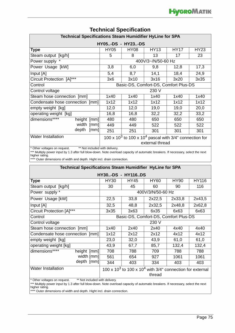
Technical SpecificationTechnical Specifications Steam Humidifier HyLine for SPA
HY05..-DS - HY23..-DS Type HY05 HY08 HY13 HY17 HY23Steam output [kg/h] 5 8 13 17 23Power supply * 400V/3~/N/50-60 HzPower Usage [kW] 3,8 6,0 9,8 12,8 17,3
Input [A] 5,4 8,7 14,1 18,4 24,9Circuit Protection [A]*** 3x6 3x10 3x16 3x20 3x35Control Basic-DS, Comfort-DS, Comfort Plus-DSControl voltage 230 VSteam hose connection [mm] 1x40 1x40 1x40 1x40 1x40Condensate hose connection [mm] 1x12 1x12 1x12 1x12 1x12empty weight [kg] 12,0 12,0 19,0 19,0 20,0operating weight [kg] 16,8 16,8 32,2 32,2 33,2dimensions**** height [mm]
width [mm]depth [mm]
480 480 650 650 650449 449 522 522 522251 251 301 301 301
Water Installation 100 x 103 to 100 x 104 pascal with 3/4" connection for external thread
* Other voltages on request. ** Not included with delivery.*** Multiply power input by 1.3 after full blow-down. Note overload capacity of automatic breakers. If necessary, select the next higher rating.**** Outer dimensions of width and depth. Hight incl. drain connection.
Technical Specifications Steam Humidifier HyLine for SPA
HY30..-DS - HY116..DSType HY30 HY45 HY60 HY90 HY116Steam output [kg/h] 30 45 60 90 116Power supply * 400V/3/N/50-60 Hz
Power Usage [kW] 22,5 33,8 2x22,5 2x33,8 2x43,5
Input [A] 32,5 48,8 2x32,5 2x48,8 2x62,8Circuit Protection [A]*** 3x35 3x63 6x35 6x63 6x63Control Basic-DS, Comfort-DS, Comfort Plus-DSControl voltage 230 VSteam hose connection [mm] 1x40 2x40 2x40 4x40 4x40Condensate hose connection [mm] 1x12 2x12 2x12 4x12 4x12empty weight [kg] 23,0 32,0 43,9 61,0 61,0operating weight [kg] 43,9 67,7 85,7 132,4 132,4dimensions**** height [mm]
width [mm]depth [mm]
708 788 709 788 788561 654 927 1061 1061344 403 334 403 403
Water Installation 100 x 103 to 100 x 104 with 3/4" connection for external thread
* Other voltages on request. ** Not included with delivery.*** Multiply power input by 1.3 after full blow-down. Note overload capacity of automatic breakers. If necessary, select the next higher rating.**** Outer dimensions of width and depth. Hight incl. drain connection.
Page 75

Page 76
14. Exploded View
30
32
42
1
12
35
31
3
15
38
14
21
20
39
22
37
6
2
16
84
18
43
44
17
25
19
31
48
22
22
22
24
23
64
61
63
62
66
67
67
60 65
58
22
Special model„HyFlow“

Page 77
15. View of housing

12/2004
Lise-Meitner-Str.3 • D-24558 Henstedt-UlzburgPhone +49(0)4193/ 895-0 • Fax -33eMail [email protected] • www.hygromatik.comA member of the Group