Embed Size (px)
Citation preview

FlexLineElectrode Steam Humidifiers
ÁFLE.CSAoÈFLE.CSAE-8881762
IMPORTANT: READ AND SAVE THESE INSTRUCTIONS
Manual

Page 2
Risk of electrical shock!Hazardous electrical high voltage!All electrical work to be performed by certified expert staff (electricians or expert personnel witheqivalent training) only.
Certain computer programs contained in this product [or device] were developed by HygroMatikGmbH ("the Work(s)").
Copyright © HygroMatik GmbH [03.12.2018]
FLE 05/10/15/20/25/30/40/50/65/80/100/130 CSA
All Rights reserved.
Current version of this manual can be found at: www.hygromatik.co.uk
HygroMatik GmbH grants the legal user of this product [or device] the right to use the Work(s)solely within the scope of the legitimate operation of the product [or device]. No other right isgranted under this licence. In particular and without prejudice to the generality of the foregoing,the Work(s) may not be used, sold, licensed, transferred, copied or reproduced in whole or inpart or in any manner or form other than as expressly granted here without the prior written con-sent of HygroMatik GmbH.
Information in this manual is subject to change or alteration without prior notice.

1. Introduction ....................................................................................................................... 51.1 Typographic Distinctions ................................................................................................... 51.2 Documentation .................................................................................................................. 51.3 Symbols in Use ................................................................................................................. 51.3.1 Specific Symbols related to Safety Instructions ............................................................. 51.3.2 General Symbols ............................................................................................................ 51.4 Intended Use ..................................................................................................................... 62. Safety Instructions ............................................................................................................ 72.1 Guidelines for Safe Operation ........................................................................................... 72.1.1 Scope ............................................................................................................................. 72.1.2 Unit control ..................................................................................................................... 72.1.3 Unit Operation ................................................................................................................ 72.1.4 Mounting, dismantling, maintenance and repair of the unit ............................................ 82.1.5 Electrical ......................................................................................................................... 82.2 Disposal after dismantling ................................................................................................ 83. Transport ............................................................................................................................ 93.1 Overview ........................................................................................................................... 93.2 Packing .............................................................................................................................. 93.3 Interim Storage .................................................................................................................. 93.4 Check for Complete and Correct Delivery of Goods ......................................................... 94. Functional Description and Device Composition .......................................................... 104.1 Mode of Action .................................................................................................................. 104.2 Mechanical Construction ................................................................................................... 104.3 Operating sequence .......................................................................................................... 115. Mechanical installation ..................................................................................................... 125.1 Environment Parameters to be met and Mounting Recommendations ............................. 125.1.1 Dimensions and Mounting Directions ............................................................................. 135.2 Unit Installation Check ....................................................................................................... 165.3 Absorption Distance BN .................................................................................................... 175.3.1 Determining the Absorption Distance ............................................................................. 175.3.2 Absorption Distance Nomogram .................................................................................... 185.4 Steam Manifold ................................................................................................................. 195.4.1 General installation guidelines ....................................................................................... 195.4.2 Recommendations for dimensioning .............................................................................. 195.5 Steam line and condensate hose layout .......................................................................... 225.5.1 Guide lines for steam line design .................................................................................. 225.5.2 Condensate hose layout ................................................................................................. 225.5.3 Steam line and condensate hose installation types ....................................................... 236. Water connection .............................................................................................................. 246.1 Operation with softened water ........................................................................................... 246.2 Water supply ..................................................................................................................... 256.3 Water discharge ................................................................................................................ 256.4 Water connections final check ........................................................................................... 26
Page 3

7. Electrical connection ........................................................................................................ 277.1 Electrical installation approach .......................................................................................... 277.2 Cable connections ............................................................................................................. 287.3 Connection of interlock (safety) system ............................................................................ 297.4 Full wiring diagrams .......................................................................................................... 297.5 Electrical installation check list .......................................................................................... 298. Commissioning ................................................................................................................. 309. Maintenance ....................................................................................................................... 319.1 General .............................................................................................................................. 319.1.1 Service messages .......................................................................................................... 319.1.2 Service messages for preventive maintenance .............................................................. 319.1.3 Safety instructions for maintenance ............................................................................... 329.2 Maintenance frame work ................................................................................................... 339.3 Removal and reinstallation of the steam cylinder .............................................................. 349.4 Steam cylinder, electrodes and cylinder base cleaning .................................................... 389.5 Checking cable connections .............................................................................................. 389.6 Solenoid valve removal/reinstallation and fine filter cleaning ............................................ 399.7 Cleaning of blow-down pump ............................................................................................ 409.8 Inspection of hoses ........................................................................................................... 419.9 Electrode replacement ...................................................................................................... 419.10 Functional check ............................................................................................................. 429.11 Finishing maintenance .................................................................................................... 4210. Dismantling ...................................................................................................................... 4311. CSA Certificate of Compliance ...................................................................................... 4412. Spare Parts ...................................................................................................................... 4713. Technical specifications ................................................................................................. 5014. Exploded view ................................................................................................................. 5215. View of housing ............................................................................................................... 53
Page 4

1. IntroductionDear Customer,Thank you for choosing a HygroMatik steamhumidifier.
HygroMatik steam humidifiers represent thelatest in humidification technology.
In order to operate your HygroMatik steamhumidifier safely, properly and efficiently,please read these operating instructions.
Employ your steam humidifier only in soundcondition and as directed. Consider potentialhazards and safety issues and follow all therecommendations in these instructions.
If you have additional questions, please con-tact your expert dealer.
For all technical questions or spare partsorders, please be prepared to provide unittype and serial number (see name plate onthe unit).
1.1 Typographic Distinctions• preceded by a bullet: general speci-
fications
» preceded by an arrow: Procedures for servicing or maintenance which should or must be performed in the indicated order
Installation step which must be checked off.
italics Terms used with graphics or drawings
1.2 Documentation
In addition to this manual, the appropriateFlexLine Control documentation is mandatoryfor the operation of the unit.
RetentionPlease retain these operating instructions ina secure, always accessible location. If theproduct is resold, turn the documentationover to the new operator. If the documenta-tion is lost, please contact HygroMatik.
Versions in Other LanguagesThese operating instructions are available inseveral languages. If interested, please con-tact HygroMatik or your HygroMatik dealer.
1.3 Symbols in Use
1.3.1 Specific Symbols related toSafety Instructions
According to ANSI Z535.6 the followingsignal words are used within this document:
DANGER indicates a hazardous situationwhich, if not avoided, will result in death orserious injury.
WARNING indicates a hazardous situationwhich, if not avoided, could result in death orserious injury.
CAUTION indicates a hazardous situationwhich, if not avoided, could result in minor ormoderate injury.
NOTICE is used to address practices notrelated to physical injury.
1.3.2 General Symbols
This symbol is used whenever a situationrequires special attention beyond the scopeof safety instructions.
Page 5

1.4 Intended Use
HygroMatik electrode steam humidifiersserve for steam production based on tapwater or partially softened water. Only use supply water featuring a con-ductivity of 125 to 1250 µS/cm.
D1: Lower threshold
C1: Range of reduced conductivity (adjustment required)
A: Normal Tap water
B: Range of increased conductivity
C2: Range of high conductivity (adjustment required)
D2: Upper threshold
In the C1 and C2 ranges, adaptation of theperiodic blow-down frequency may berequired. Pls. refer to parameter „2-1“ and „2-2“ explanations given in the „Detailed param-eter descriptions“ section.
Proper usage also comprises the adherenceto the conditions specified by HygroMatik for:• installation • dismantling • reassembly • commissioning • operation• maintenance• disposal.
Only qualified and authorised personnel mayoperate the unit. Persons transporting orworking on the unit must have read andunderstood the corresponding parts of theOperation and Maintenance Instructions andespecially the chapter 2. „Safety Notes“.Additionally, operating personnel must beinformed of any possible dangers. Youshould place a copy of the Operation andMaintenance Instructions at the unit‘s opera-tional location (or near the unit).By construction, HygroMatik steam humi-difiers are not qualified for exterior appli-cation.
Risk of scalding!Steam with a temperature of up to 100 °C(212° F) is produced.Do not inhalate steam directly!
Page 6

2. Safety InstructionsThese safety instructions are required by law.They promote workplace safety and accidentprevention.
2.1 Guidelines for Safe Opera-tion
2.1.1 ScopeComply with the accident prevention regula-tion „DGUV Regulation 3“ to prevent injury toyourself and others. Beyond that, nationalregulations apply without restrictions.
2.1.2 Unit control Do not perform any work which compromisesthe safety of the unit. Obey all safety instruc-tions and warnings present on the unit.In case of a malfunction or electrical powerdisruption, switch off the unit immediately andprevent a restart. Repair malfunctionspromptly.
Restricted use.IEC 60335-1 stipulates as follows:This device may be used by children of eight years of age and above as well as by persons with reduced physical, sensory or mental ca-pabilities or lack of experience and knowledge so long as they are supervised or have been instructed regarding the safe use of the de-vice and understand the hazards that may re-sult from it. Cleaning and user maintenance of the unit must not be undertaken by children without supervision.
2.1.3 Unit Operation
Risk of scalding!Uncontrolled hot steam escape in case ofleaking or defective components possible.Switch off unit immediately.
Risk of material damage!The unit may be damaged if switched onrepeatedly following a malfunction withoutprior repair.Rectify defects immediately!
The unit must not be operated on a DCpower supply.
The unit may only be used connected to asteam pipe that safely transports the steam.
Regularly check that all safety and monito-ring devices are functioning normally. Do notremove or disable safety devices.
Page 7

2.1.4 Mounting, dismantling, mainte-nance and repair of the unit
The HygroMatik steam humidifier is IP20 pro-tected. Make sure that the unit is not object todripping water in the mounting location.Installing a humidifier in a room without waterdischarge requires safety devices to protectagainst water leakages.
• Use genuine spare parts only• After any repair work, have qualified
personnel check the safe operation of the unit
• Attaching or installing of additional components is permitted only with the written consent of the manufacturer
2.1.5 Electrical
Risk of electrical shock!Hazardous electrical voltage!Any work on the electrical system to be per-formed by certified expert staff (electriciansor expert personnel with comparable training)only.
Disconnect unit components from electricalpower supply prior to work.After electrical installation or repair work, testall safety mechanisms (such as groundingresistance).
Use only original fuses with the appropriateamperage rating.Regularly check the unit‘s electrical equip-ment. Promptly repair any damage such asloose connections or burned wiring.
Responsibility for intrinsically safe installationof the HygroMatik steam humidifiers isincumbent on the installing specialist com-pany.
2.2 Disposal after dismantling
The operator is responsible for the disposalof unit components as required by law.
Page 8

Page 9
3. Transport3.1 Overview
Proceed carefully when transporting thesteam humidifier in order to prevent damagedue to stress or careless loading and unload-ing.
3.2 Packing
Pay attention to the icons affixed to the pack-ing box.
3.3 Interim Storage
Store the unit in a dry place and protect fromfrost and strong sunlight.
3.4 Check for Complete and Cor-rect Delivery of Goods
Upon receipt of the unit, confirm that:
• model and serial number on the name plate match those specified in the order and delivery documents
• the equipment is complete and all parts are in perfect condition
In case of damage from shipment and/ormissing parts, immediately notify the carrieror supplier in writing.
Time limits for filing freight claims with ship-ping companies are*:
* Time limits for some services subject tochange.
Shipping company After receipt of goods
Carriers no later than 4 days
Parcel service immediately

s-
or
4. Functional Description and Device Composition
4.1 Mode of ActionMaking use of the frictional heat causedby current flow in a water tankThe HygroMatik humidifier utilizes the con-ductivity normally present in tap water forsteam production. Electrodes inside anenclosed steam cylinder are immerseddirectly into the tap water. They are con-nected to the alternating current. The con-ductivity of the water generates an electriccurrent between the electrodes. In this way,the electric power supplied is converteddirectly into heat without energy loss. Thesteam produced has a temperature of about100°C (212°F) with minimal excess pressure("pressureless steam"). It is largely free ofminerals and germ-free. Mineral deposits typ-ically remain behind in the cylinder.
4.2 Mechanical Construction
The FlexLine humidifiers are designed forwall mounting. For maintainance purposes,the steam cylinders are separable in the mid-dle.
Starting with the manufacturing date of 11/2018, the steam humidifiers FLE50/65/100/130 make use of a modified steam cylinderthat are separable in the upper part of thewall. When replacing the steam cylinder, thenew cylinders with the designation „CY45/2“may be incorporated in the older units aswell. With the steam cylinder modificationalso the electrodes have changed. The newelectrodes only fit in the new steam cylinders.
The cylinders CY45/2 allow for unit operationwithout a cylinder star even in case of highconductivity of the cylinder water.
Steam cylinder
Steam exit
Manual drain hose
Solenoid valve
Water inlet
Blow-down pump
Cicuit breaker
Current tranducer
Mainboard(Control)
Main contact
Display
Control switch
Cablebushings
Waste wateroutlet
Cylinder base
Electrode plugs
Steam hoseadapter
Electrodes
Page 10

4.3 Operating sequence
By pressing the control switch („Pos. I”) the humidifier is turned on. When the controller specifies an increase in humidity, the main contactor is switched on and the electrodes (48)*) are supplied with power. The water inlet solenoid valve (25)*) feeds water into the steam cylinder (16)*).
As soon as the electrodes are immersed, thecurrent begins to flow. The water is nowheated. When the pre-selected output isreached, the control turns off the solenoidvalve and interrupts the water supply.
After a short heating up period, the waterbetween the electrodes begins to boil andvaporize. The vaporization lowers the waterlevel in the steam cylinder, reducing the out-put provided. The inlet solenoid valve,equipped with a fine mesh filter, intermittentlyadmits fresh water.
Humidifier power usage is continuously mon-itored. With a cold start-up, the nominal cur-rent increases to 113% in order to achievequick-start output parameters. This activatesthe electronic overflow limiter which causes apartial draining of the cylinder. This reducesthe immersed surface area of the electrodes,lowering power usage.
The concentration of dissolved saltsincreases over time, which can lead to a risein the conductivity of the water. If this contin-ues, conductivity may increase until a shortcircuit occurs. This could damage the unit,but in any case would significantly reduce thelife span of the electrodes.
For this reason, regular, periodic blow-downsof some of the concentrated water are veryimportant. Following this procedure as rec-ommended provides stable cylinder waterconductivity as well as minimal water loss forthe expected service life of the cylinder.
Water blow-down is performed by a blow-down pump 32)*). The functioning of theblow-down pump is continuously monitoredduring operation. If the pump is damaged, thesteam humidifier shuts down.
With normal water quality the blow-down lossrate lies between 7 and 15 % of the amountof steam produced. Depending on waterquality, a full steam cylinder blow-down is runevery 3 to 8 days.
Mineral deposits settle in the open areabelow the electrodes and are removedthrough periodic maintenance. The blow-down pump itself has wide openings and canflush out smaller pieces of mineral deposit.This extends the service life of the unit andreduces the required maintenance interval.
On blow-down, water flows from the pumpinto the drainage system.
For maintainence purposes, the cylinderwater may be pumped out by pressing andholding the control switch in the „II“ position.
Monitoring max. levelA sensor electrode (10)*) monitors the maxi-mum water capacity of the cylinder. When thewater level reaches the sensor electrode, thewater supply is interrupted. This can occurwhen the water has low conductivity or whenthe electrodes are worn out. In the case oflow water conductivity, however, this stateusually lasts only a short time. The built-incontrol and the large area electrodes com-bine to produce a rapid rise in conductivity byincreasing the concentration of the water.
*) numbers indicated correspond with thosein the exploded view in the „Exploded view“chapter.
Page 11

Page 12
5. Mechanical installation
Risk of foot injuries!Prevent unit from dropping during installation!Helping hand of a second person is advis-able.
Risk of electrical shock!Hazardous electrical voltage.During installation, the unit must be discon-nected from power supply.
5.1 Environment Parameters tobe met and Mounting Recom-mendations
When selecting the installation site for thesteam humidifier, take the following intoaccount:
• The minimum clearances indicated inthe fitting measures section must beobserved in order to ensure adequateunit ventilation and allow for unobstruc-ted access in case of maintenance
• Protection class IP20
• By design, HygroMatik steam humidi-fiers are not qualified for outdoor instal-lation (electronical components andwater-bearing parts may be damaged)
• Ambient temperature must lie between+5 and +40 °C (+41 and +104 °F) inorder to protect the unit electronicsagainst damage; frost may damage thesteam cylinder, the solenoid valve andpump, as well as make hoses burst
• Relative humidity must not exceed80 % r.h., since values beyond maylead to electronic malfunction or dam-age
• Installation in a closed room requiresaeration and, eventually, temperatureconditioning in order to meet the a.m.environmental conditions
• The steam humidifier should beinstalled as close as possible to thesteam manifold. Optimum perfor-mance is only guaranteed when steamand condensate hoses are kept short
• Make use of existing water connectionsfor supply and draining
• Hoses must be laid at a consistent 5 to10 % incline/decline; sagging and kin-king prevention is a must
• Mount the unit on a stable, preferablysolid wall offering the bearing capacityrequired (s. unit technical specificati-ons). If such a wall is not at hand, theunit may be attached to a stand bracketfirmly bolted to the floor
• For proper functioning of the level con-trol, plumb and level installation of theunit is required
• The steam humidifier rear panel heatsup during operation to a maximum of70 °C (158 °F). Take care that the con-struction on which the unit is to bemounted is not made of temperature-sensitive material

5.1.1 Dimensions and Mounting Directions
Table of dimensions
Model X [mm/inch] Y [mm/inch] Z [mm/inch] A [mm/inch] B[mm/inch]FLE05-FLE10 540/~21.3 535/~21 320/~12.6 390/~15.4 400/~15.7FLE15-FLE25 540/~21.3 695/~27.4 320/~12.6 390/~15.4 560/~22FLE30-FLE40 580/~22.8 750/~29.5 355/~14 425/~16.7 620/~24.4FLE50-FLE65 640/~25 785/~30.9 420/~16.5 490/~19.3 650/~25.6FLE80 1130/~43.1 750/~29.5 420/~16.5 870/~34,4 620/~24.4FLE100-FLE130 1170/~46 785/~30.9 420/~16.5 1000/~39.4 660/~25.6
Z
X
Y
�
�� �
�
Detailed measurements under https://www.hygromatik.com/files/pdf/hygromatik-flexline-dimensionsv13.pdf .3D models under https://www.hygromatik.com/en/downloads
Page 13

Wall clearancesWhen mounting the steam humidifier, thewall clearances shown in the fig. below mustbe obeyed:
Mounting principle
For wall mounting drill measures, pleaseconsult the table above (measure A). In caseof no suitable wall available for mounting theunit, it is recommended that installation ismade on brackets firmly anchored in thefloor.
» mark the holes for the upper sus-pension brackets screws
» drill holes and dowel » screw in the supplied mounting
screws; let the screws protrude approx. 12 mm/.5 inch from wall
» ensure firm fixation and load-carry-ing capacity of the mounted screws!
» hook in the unit and ensure safe suspension
» mark the holes for the lower suspen-sion brackets screws
» remove the unit» drill holes and dowel» hook in the unit and mount the lower
screws firmlyTo function properly, the steam humidifiermust hang level and plumb.
>500/19.7>200/7.8
>300/11.8
>50/2.0
device rear
suspension brackets
all measures in mm/inch
Page 14

Device connections:
Cable entries
1¼“ Waste water connection
¾“ Water inlet
DN25, DN40 Steam outlet
Page 15

Page 16
5.2 Unit Installation CheckBefore start-up, pls. check proper unit instal-lation following the list below:
Unit perpendicularly aligned in both the vertical and horizontal axis ?
All clearances obeyed? Steam hose installed with a 5 - 10 %
minimum incline/decline (see chap-ter "Steam line“) ?
Condensate hose features a loop functioning as a steam barrier (see chapter „Condensate hose“) ?
Steam manifold(s) properly positio-ned?
All bolts and clamps properly tighte-ned?
Steam manifold(s) horizontally mon-ted and suspended on the free end, if required ?
All seals (o-rings) in place?
All ventilation slots on housing top unobscured?

Page 17
5.3 Absorption Distance BN The "absorption distance" (BN) is defined asthe distance from the steam feed to wherethe steam is completely absorbed in thetreated air. Within the absorption distance,steam is visible as mist in the air stream.
Condensation may occur on anythinginstalled within the absorption distance.
Although steam outside the absorption dis-tance (BN) is completely absorbed, it is notyet evenly diffused in the duct. If you plan toinstall any parts or devices inside the absorp-tion distance, such as sensors or elbows, werecommend increasing the absorption dis-tance using the formulae below. The absorp-tion distances required for certain installedfittings are distinguished by separate sym-bols and calculated as a multiplier of theabsorption distance BN.
The absorption distance has no fixed value,but depends on many factors. These aredepicted in the absorption distance nomo-gram below.
5.3.1 Determining the AbsorptionDistance
To determine the absorption distance, the fol-lowing parameters are required:
• Air humidity before humidification x1 in g/kg
• Air temperature after humidification t2 in °C (with steam humidifiers the change in air temperature due to humidification may be disregarded t1 or t2)
• Specific increase in humidity x in g/kg (can be determined in the h,x diagram)
• quantity of steam introduced in kg/h.
• air speed wL in m/s in air duct
• Total length lD of the steam manifold installed in the air duct
Length ID of the usable steam manifolddepends on the dimensions of the air duct.The length of the absorption distance can bereduced by using multiple steam manifolds(also see section on the steam manifold).
Method:Graphically determine absorption distanceBN using the absorption distance nomogram(also see Section „Absorption DistanceNomogramm“). Enter the value of the param-eters enumerated above into the respectivequadrants. The resulting point of intersectionindicates the value of the desired absorptiondistance BN.
Notes:Air humidity before humidification x1:....[g/kg]
Air temperature after humidification t2:.....[°C]
Specific increase in humidity x:...........[g/kg]
Quantity of steam introduced :.........[kg/h]
Air speed WL:..........................................[m/s]
Total length of steam manifold lD:...........[mm]
o
Dm
o
Dm
Absorption Distance BN for normal obstructions
such as sensors, ventila-tors, outlets
Bc = (1.5...2) x BN for fine fiters, heat regis-ters
Bs = (2.5...3) x BN for particle filtersBd = (3...5) x BN for humidity sensors,
duct humidistats

Page 18
5.3.2 Absorption Distance Nomogram
Source: Henne, Erich: Luftbefeuchtung (Air Humidification), 3rd Edition 1984 (Page 101), Olden-bourg Industrieverlag, Munich

L3
5.4 Steam Manifold
5.4.1 General installation guidelines
When installing steam manifolds, pls. followthese guidelines:
Positioning within duct• Install the steam manifold as close as
possible to the steam humidifier in order to minimize steam loss through condensation
• Steam manifold placement on the sup-ply side of the air duct is preferable
• Install steam manifold strictly horizontalin order to ensure proper condensatedrain
• Shown installation and positioningdimensions are based on empiricvalues. Special environmental conditi-ons may require adjustments. Payspecial attention to avoid condensategeneration in air duct
Allowable pressures• Max. allowable pressure in air duct is
1500 Pa/.218 PSI (exemption: SLE02only allows for 1200 Pa/.174 PSI)
• On suction side, max. -500 Pa (.07PSI) is tolerable
• With high-pressure air conditioningsystems, modifications of the unit‘sdrain hose system may possibly berequired depending on the overall pres-sure situation. These modificationsmust be coordinated with yourexpert dealer.
Water drain• We point out that according to the Ger-
man Association of engineers (VDI)guideline VDI 6022, a water drain mustbe provided within the absorptiondistance inside the air duct
When increased airflow speed is encoun-tered• Air flow rates beyond 3m/s (9.84 ft/s)
may lead to condensate drainage prob-lems at the steam manifolds due tovacuum built-up. A possible remedy istwisting the steam manifold in its hori-zontal axis by few angular degrees. Incase of problems, pls. consult yourexpert dealer.
5.4.2 Recommendations for dimen-sioning
The recommendations given below arebased on homogenous air flow in the duct.
Horizontal installation of steam manifold
Standard steam manifold arrangement:
An even distribution of steam manifolds ensu-res a uniform steam distribution.
Please use the total hight of the duct!
L1=L2=
Air flowdirection
Steam manifold(Side view)
Air duct
l*) (depends on duct dimension)
4.7 inch 3.5 inch 2.8 inch
120 mm 90 mm 70 mm
1.5 mm.06 inch
Page 19*) s. table of manifold lengths Horizontal assembly position in duct
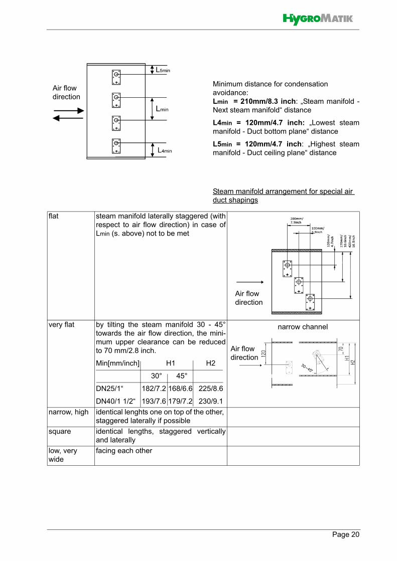
Minimum distance for condensation avoidance:Lmin = 210mm/8.3 inch: „Steam manifold -Next steam manifold“ distance
L4min = 120mm/4.7 inch: „Lowest steammanifold - Duct bottom plane“ distance
L5min = 120mm/4.7 inch: „Highest steammanifold - Duct ceiling plane“ distance
Steam manifold arrangement for special air duct shapings
Air flowdirection
flat steam manifold laterally staggered (withrespect to air flow direction) in case ofLmin (s. above) not to be met
very flat by tilting the steam manifold 30 - 45°towards the air flow direction, the mini-mum upper clearance can be reducedto 70 mm/2.8 inch.
Min[mm/inch] H1 H2
30° 45°
DN25/1“ 182/7.2 168/6.6 225/8.6
DN40/1 1/2“ 193/7.6 179/7.2 230/9.1narrow, high identical lenghts one on top of the other,
staggered laterally if possiblesquare identical lengths, staggered vertically
and laterallylow, very wide
facing each other
Air flowdirection
Air flowdirection
Air flowdirection
narrow channel
Page 20

Vertical steam manifold installation
Horizontal installation of the steam mani-folds is preferable. However, verticalinstallation into the air duct from below isalso possible.
Standard manifold dimensions [mm]/[inch]***:
*** Special lengths on demand.
**** will be replaced in 2019 by 1500 mm / 59,1 inch longsteam distributors
Number and size of the steam manifoldsavailable as well as the nominal diameterof the repective steam and condensatehoses may be taken from the tablesshown in chapter „Technical Data“.
220/8.7
400/15.7
600/23.6
900/35.4
1200/47.2
1450****/57.1
Steam manifold arrangement
Steam supply
Air flow direction
Page 21

5.5 Steam line and condensatehose layout
Because of the high requirements on hosematerial under the operating conditionsgiven, it is recommended to use genuineHygroMatik hoses only.
5.5.1 Guide lines for steam linedesign
• Steam hose nominal diameter must not be smaller than the steam outlet of the HygroMatik steam humidifier (do not restrict the cross-section, otherwise back pressure will increase)
• Steam hoses must be laid without sags and kinks and with a continuous slope of 5-10% (otherwise sags may result).
• Steam hoses must be supported every 500 mm (20 inches) by clamp brackets
• Steam hoses should be kept as shortas possible. Implement lengths be-yond 5 m (16 ft.) as insulated fixedpiping to keep energy loss and conden-sate generation to a minimum. Beyond10 m (32 ft.) insulated installation is amust. Fixed piping is generally recom-mended for straight steam line seg-ments
• When 2 steam manifolds are in use(other than with a standard implemen-tation), place steam Y piece as close aspossible to the steam manifolds. Such,for the main part of the piping just onesteam hose is required and condensateloss is minimized
• Allow easy access to the steam pipe/steam hose installation
• Pressure conditions within the duct are influenced by device steam output, steam line layout and the duct compo-sition itself. In some rare situations it may become necessary to optimize steam line layout for achieving the results intended
• Respect minimum bending radii:
DN 25 Steam hose: Rmin = 200 mm/8“ DN 40 Steam hose: Rmin = 400 mm/16“
5.5.2 Condensate hose layoutThe condensate hose may be run from thesteam manifold back to the steam cylinder,as depicted in the schematic drawing belowwith concern to installation type 1. Alterna-tively, the condensate hose may be feddirectly in a wastewater pipe or a drain (s.installation type 2).
Should condensate return into the steam cyl-inder be intended, the connection stub on thecylinder upper part must be drilled out firstwith a ANSI drill size „O“ drill. To do so, thesteam cylinder must be removed from thehousing (s. maintenance chapter, section„Steam cylinder removal and reinstallation“).
with an 8 mm (ANSI drill size „O“) drill,Drill out condensate hose connection stub
Steam cylinder top view
if required
Page 22

l „x“
inch6 inch
8 in
ch
5.5.3 Steam line and condensatehose installation types
Installation type 1
Steam manifold is positioned more than500 mm above device upper edge:
» Run steam hose to a height of 400 mm/16 inch minimum above the steam humidfier and then to the steam manifold with a continous incline of 5 to 10 %.
» Feed condensate hose from steam manifold with a decline into waste-water pipe or drain.
» As a steam barrier, lay out a 200 mm/8 inch min. loop (s. schematic representation below). Minimum distance from steam manifold to loop must be 500 mm/20 inch. Fill loop with water prior to steam humi-difier commissioning.
Installation type 2
Steam manifold is positioned less than500 mm above or below device upperedge:
In this arrangement the condensate hosecannot be fed back to the steam humidifier.
» Run steam hose to a height of 400 mm/16 mm minimum above the steam humidfier and then to the steam manifold with a continous decline of 5 to 10 %.
» Feed condensate hose to a waste-water pipe/drain with a 200 mm/8 inch diameter loop as a steam bar-rier. Minimum distance from steam manifold to loop must be 500 mm/20 inch. Fill loop with water.
Steam cylinder
Steam manifoldSteamhose
Condensate
hose
Installation type 1,
Deviceupper edge
schematic representation
500 mm20 inchmin.
400
mm
16 in
ch
200 mm/8‘‘ min
RminDN25: 200 mm/8 inchDN40: 400 mm/16 inch Steam cylinder
Steamhose
Deviceupper
Condensatehose
Drain
Detail „x“wrong!
Installation type 2,schematic representation
edgeDetai
RminDN25: 200 mm/8DN40: 400 mm/1
400
mm
16 in
ch
200
mm
Page 23

6. Water connection
Risk of scalding!Very hot water to be found in and around thesteam humidifier during and after operation.Have all installation work done by expert staffin order to avoid scalding hazards due toimproper water guidance.
Risk of electrical shock!Hazardous electrical high voltage!Before starting installation work ensure thatthe unit is not yet connected to the powersupply.
General Rules
• Obey local water utility regulations• Verify that necessary safety mea-
sures have been taken – in compli-ance with either German Technical and Scientific Association for Gas and Water (DVGW) guidelines (DIN EN1717) or local regulations – to eliminate backflow of polluted water into drinking water treatment facili-ties. This may require the installation of a system separator and free discharge into the drainage system. Within the humidifier, a double check valve (58) is located in the water supply line. It prevents - in accordance with DIN EN 61770 - the backflow of water. As an option for installation by the customer, the DVGW-conform HyFlow system separator or a after market system separator of the BA/CA type are available from HygroMatik.
• Use feed water without chemical additives and with a conductivity between 200 and 800 µS/cm only. Beyond conductivity levels of 800µS/cm up to a maximum of 1250µS/cm and below conductivity levels of 200µS/cm to a minimum of 125µS/cm, special adjustments are required. In this case please contact your specialist dealer
• Supply water must not exceed 40 °C (104 °F)
• Allowable range of water pressure: 100000 to 1000000 Pa (14.5 to 145
psi)• For connection to the water supply
pipe, make use of a water hose • Blow-down water must drain freely
6.1 Operation with softenedwater
Do not use softened water unless specialmeasures are taken!When feeding softened water into the Hygro-matik steam humidifier, the aspects outlinedbelow must be taken into account.
Softened water may cause• unacceptably high conducivity• the formation of salt bridges
between the electrodes and the electrode leads on the inner surface of the steam cylinder upper part
• foaming in the steam cylinderSalt bridges may cause electrical arcs. Theseare indicated by the presence of blackgrooves in the top part of the cylinder. Thecylinder must then be replaced to prevent fur-ther damage to the cylinder material, as wellas short circuits which may trip main circuitbreaker.
Foam may come into contact with the maxi-mum level sensor electrode and trigger themax. level status message despite the cylin-der not being full yet and the nominal currentnot yet established.
With softened water, at operating tempera-ture conductivity level usually is higher thanis the case with tap water.
If using a water softening system, we recommend diluting the softened water with normal tap water to produce an overall hardness between 4-8°gH. This value can be set lower if the water does not foam.
Page 24

6.2 Water supply
Foreign material in water supply pipe maycause premature wear of the solenoidvalve.Flush the water supply pipe before makingconnection to the solenoid valve. This is ofparticular importance in case of a newlyinstalled pipe.
» Install a shut-off valve (AV) in the supply line.
» Install a water filter (WF) if required due to bad water quality.
In case of no safety device for drinking waterprotection according to DIN EN 1717 presentin the house installation system, a systemseparator at least of the CA type or use of theHyflow retrofit option is mandatory.
Shut-off valve (SV) and water filter (WF) arenot included in the delivery.
For connection to the water supply line, thewater hose (56) with cap nuts on both endssupplied with the unit may be used.
Make connection as follows:
» Attach cap nut with inner seal ring toinlet screw joint on the humidifierhousing and tighten.
Do not overtighten the cap nut!Excessive tightening will destroy the fitting.
Strainer must be placed inside the solenoidvalve.
» Screw the other hose end cap nutwith its inner seal on a customer-provided water tap (cap nut internalthread is ¾“) .
6.3 Water discharge
Risk of scalding!During blow down up to 0.3 l/sec (.08 gal./sec) are being drained with a temperature ofabout 95 °C (203 °F).Ensure that the drain hose is reliably fas-tened and wastewater can drain freely andpressureless.
Humidifier installation location and wastewa-ter discharge must be on the same pressure level.
Water supply100000 - 1000000 Pa (14.5 - 145 psi)
3/4” connection
SV
Page 25

Guidelines for water discharge composi-tion
• Use flexible water hose• Do not buckle drain hose• Discharge line and drain pipe material
must be temperature resistant up to95°C (203 °F)
How to proceed
» Run a 1 1/4 " drain hose of 250 to1000 mm (10 to 40 inch) length intoa pressure-free outlet according toDIN EN 1717. The hose must beguided sideways of the humidifier toprevent ascending vapor from con-densating on the humidifier`shousing.
» Fit drain hose to connection stub on humidifier housing bottom side.
Grounding clip functioning
The two grounding clips attached to the innersurface of the housing drain stub are in directcontact with water and shunt potential resi-dual electric currents away from the housingduring blow-down and in case of a cylinderwater overflow.
Between the pump drain hose jacket and theinner surface of the cabinet drain connection,a gap exists due to the diverging diameters. Ifwater collects on the base plate, it will flowthrough this gap into the drain hose and theninto the drainage system.
With the optional wastewater cooling systemHyCool, HygroMatik offers an option for limi-ting the steam humidifier wastewater temper-ature in order to protect thermosensitivewastewater pipe lines. By blending with tapwater during blow-down and rinse pro-cesses, wastewater temperature is below60 °C (140 °F) as long as inlet water temper-ature does not exceed 30 °C (86 °F).
6.4 Water connections finalcheck
Go down the following water installationchecklist:
All screws and clamps properly tigh-tened?
Water supply line flushed before making connections?
Water connection properly installed?
Water discharge properly installed? Does blow-down water drain freely?
Water supply line and water discharge leakage-free?
Drain hose from pump
Grounding clips
Drain stub onhousng
Page 26

7. Electrical connection
Danger of electric shock!Dangerous electric voltage!All work relating to the electrical installationmay only be carried out by designated spe-cialist personnel (electrician or qualified per-son with equivalent training).
The customer is responsible for monitoringthe qualifications of the specialist personnel.
General installation rules
• All local rules concerning the imple-mentation of electrical installations must be obeyed
• Electric connector cables to be laid pro-fessionally
• Install the electrical connections accor-ding to the wiring diagram
• With units of a nominal power output > 33 kW electrical connection to a per-manent line is mandatory (according to VDE 0700 Part 98, IEC 60335-2-98)
Potential component damage due to elec-trostatic discharge!To protect the sensitive electronic compo-nents, measures to prevent damage due toelectrostatic discharge must be taken beforethe start of the installation work.
7.1 Electrical installation approach
Do not connect the steam humidifier to thelive power supply before all installation workhas been completed.
» Provide fuses with a contact gap ofat least .12 inch (3mm) per pole.
» Install a separate main connectionfor each steam cylinder includingmain circuit breaker, main switchetc. .
» Make main connection according tothe table below.
For FLE series main connection, current draw and fusing data, see chapter 13, „Technical specifications“.
HygroMatik recommends the use of slowblowing up to middle time-lag main fuses(only applies to the a.m. mains supply volt-age).
Steam humidifier installations should encor-porate an individual resiliant current circuitbreaker.
Page 27

7.2 Cable connectionsThe table below shows the quantities anddimensioning of the cable connections pro-vided by the various FlexLine housing types.
*) MSI = Multiple seal insert**) Ø 25 mm/~ 1.0 inch
Characteristics of metric cable connec-tions
*) MSI = Multiple seal insert
Model M25PG16
M25 with MSI*)
M32PG21
M40PG36
Blind plug**)
FLE05/10 1 3 3
FLE15/20FLE25
1 3 3
FLE30/40 1 1 3 3
FLE50/65 1 1 3 3
FLE80 1 2 3 3
FLE100/130
1 2 3 3
Thread Wrench size [mm/
in.]
Cable diameter sup-ported [mm/in.]
M25x1.5 30/~ 1.2 9 - 17/~ .35 - .67
M25 MSI*) 30/~ 1.2 6 (3x)/~ .24 (3x)
M32x1.5 36/~ 1.4 13 - 21/~ .51 - .83M40x1.5 46/~ 1.6 16 - 28/~ .63 - 1.1
Page 28

7.3 Connection of interlock (safety) system
Danger of electric shock!Dangerous electric voltage!After the commisioning of the unit, a 230VAC voltage is present at terminal 1 whenstandard wiring is used.
The so-called interlock (safety) system islocated between terminals 1 and 2 with termi-nal 1 holding 230 VAC. For closing the inter-lock, a make contact is required acrossterminals 1 and 2. This contact is supplied byrelay K21. For energising the relay, a makecontact or a bridge is required across theadditional terminals on the hat-top rail.
If the interlock (safety) system is open, thehumidifier does not start or the operation isinterrupted.
Safety equipment can be wired (also inseries) into the interlock (safety) system, asshown in the fig. below:
The interlock (safety) system is not closedwhen delivered ex-factory!
In air conditioning, it is standard to incorpo-rate a max. hygrostat in the interlock (safety)system. The max. hygrostat is used as asafety feature in case of a malfunction of thehumidity sensor.
7.4 Full wiring diagramsPls. find the full wiring diagrams in therespective FlexLine Control Manual:
For climate applications:
FlexLine Control Climate, chapter 7, „Wiringdiagrams“
For SPA applications:
FlexLine SPA Control , chapter 8, „Wiring dia-grams“
7.5 Electrical installation checklist
Check electrical installation with respect tocustomer-site requirements and local powersupply regulations.
Safety interlock properly wired across terminals 1 and 2 of relay K21?
Supply voltage in accordance with name plate voltage rating?
All ectrical connections made accor-ding to the wiring diagram?
R.h. sensor properly connected with respect to signal type and range (cli-mate applications only making use of a r.h. sensor)?
Temperature sensor properly connec-ted (SPA applications only)?
All screw terminal connections properly tightened?
Have all electrical cable and plug con-nections been properly tightened?
Proper unit gounding made?
2 1 L N
Terminal strip on ST1 of the main-board or ST1.1 of an extension or re-lay board
1 2
+12 VDC (internal) K21
Additional terminalson hat-top rail
Terminals 1/2 for connection of the interlock (safety) system made accessable via relay K21
Page 29

Page 30
8. Commissioning
Risk of operating error!Start-up of the unit is restricted to expert staffonly (electricians or expert personnel withequivalent training).
Step 1: Check of mechanical integrity andwiring» Open housing cover.» Check cylinder seating.» Check steam, condensate and
drainhose clamps.» Check that all electrical wire connec-
tions (including steam cylinder wir-ing) are tight and secure.
Step 2: Switching on the steam humidifier » Switch on main breaker.» Open water supply stopcock (opera-
ting pressure should be 1bar min., 10bar max.).
» Switch on unit by setting control switch to “I”.
Step 3: The unit performs a self-test and,then, commences normal operation• During self-test, the On/Off button icon
flashes for a couple of seconds• After the self-test of the controller, the
display shows the setup view for the basic device settings (language, date, time and control settings). Refer to the chapter "Commissioning" in the opera-ting instructions for the control system.
• Consequently, normal operation is commenced. However, steam is not produced without a demand pending
Step 4: Trigger steam demand» Set control to 1-step operation, i.e.
permanent steam demand, and close safety interlock.
» Allow all electrical functions to termi-nate in their programmed order.
Step 5: Monitor unit function and checkfor leakage» Let unit operate for 15 to 30 minutes.» If leaks appear, switch off the unit.
Risk of electrical shock!Hazardous electrical voltage!Follow safety instructions for work on livecomponents.
Step 6: Repair leaks» Find leaks and eliminate.» Check again for leaks.» When everything is o.k., reattach
housing cover.
9. Maintenance 9.1 General For the achievement of a long unit life span,regular maintenance is a must. Maintenanceworks to be performed refer to unit assem-blies that underlie either mechanical or elec-trical wear and tear, or may be impeded byresidues in their proper functioning.
A steam humidifier's optimal performanceand the maintenance intervals required pri-marily depend on the water quality encoun-tered and the amount of steam produced. Aparticular water quality may shorten orlengthen maintenance intervals. The amountof residues found in the steam cylinderallows for a hint on future maintenance inter-vals.
Another scenario influencing the unrestrictedunit availability is the main contactor lifetimein terms of a maximum number of switchcycles allowed, as indicated by its manufac-turer. Unit control monitors the number ofswitch cycles and produces a service mes-sage when the max. number is reached.
9.1.1 Service messagesIn case of a service message produced, theHygroMatik logo in the main section of thetouch display (for explantion s. „FlexLine con-trols“ manuals) is blanked. Instead, a frame isshown with the service icon in it and a„Service message (xx)“ („xx“ indexes themessage code). When the message frame istouched, the service message is displayed inclear language.
The service messages are listed in detail inthe „FlexLine controls“ manuals. Followinghereafter, pls. find 2 service messagesdenoted as examples:
• „Steam_amount_counter“ is output when the pre-set produced steam amount is reached
• „Cycles_main_contactor x“ is indicated when the number of cycles pre-set for main contactor „x“ (x = 1...5) is reached. The main contactor should then be replaced and the counter reset (s. „Service“ submenu in the „FlexLine controls“ manuals).
After a „Steam_amount_counter“ message,maintenance work mainly encompasseschecking and cleaning all of the unit partsincluding the steam cylinder inside, and a unittest run. Steam humidifier electrodes areprone to burn-off during steam productionand must, consequently, be replaced in aregular time frame.
As part of the maintenance work, screw ter-minals and plug connections must bechecked every time. If required, retighteningthe teminal screws is a must as well asensuring tight fit of all of the plug connec-tions.
Since steam and condensate hoses are sub-ject to wear as well, hoses must also bechecked regularly for tightness, flexibility andfirm seating.
Seals are wear parts. As such, seal integritychecks and replacement is also a part of theregular maintenance work.
9.1.2 Service messages for preven-tive maintenance
HygroMatik steam humidifiers continouslymonitor the performance of the followingfunctional areas:
• Electrode condition (wear control by means of cylinder full monitoring)
• Blow-down operations• Cylinder filling
When reaching pre-set trigger levels, unitcontrol outputs preventive service messagesthat relate to the corresponding functionalarea.
The functional area addressed should thenbe checked at short term and maintenanced,if required (s. „FlexLine controls“ manuals,„Faults and service messages“ chapter“).
Page 31

9.1.3 Safety instructions for mainte-nance
Risk of electrical shock!Hazardous electrical voltage. Unit must beswitched off and protected against restart byexpert staff (electricians or expert personnelwith equivalent training) before any mainte-nance work is commenced.
Risk of skin burning!Hot steam cylinder during operation and forsome time afterwards.Drain steam cylinder before any maintenancework is commenced. After that, wait approx.10 mins before starting maintenance work.Check steam cylinder temperature by cau-tious approximation with hand (do nottouch!).
Risk of scalding!Water pumped or drained from the steamcylinder may have a temperature of up to95 °C (203 °F). Wear proper PPE (Personal ProtectionEquipment)!
Take care of ESD protection!The electronic components of the humidifiercontrol are very sensitive to electrostatic dis-charges. In order to protect these compo-nents during maintenance, steps must betaken to guard against damage from electro-static discharge.
Page 32

9.2 Maintenance frame workMineral deposits precipitate and crystallizevery differently in different types of water,even when two types have the same conduc-tivity and hardness levels (the various constit-uents in the water interact differently).
Instructions on maintenance and cleaningintervals, or on electrode service life, arebased entirely on empirical data.
In most cases, the conductivity levels given inthe "Directions for Use" section of this manualmay be considered as typical values. Individ-ual parameter settings as part of the controlsoftware may be necessary.
Very seldomly, water pretreatment may benecessary (softening by dilution to approx. 4 -8 °gH; decarbonization/partial desalination toachieve target reductions in carbonate hard-ness).
For any questions with regard to water treat-ment systems pls. contact your expert dealer.
Cycle time Maintenance work4 weeks aftercommisioning
(with normal water quality)
Visual inspection of electrical and mechanical connections
Remove mineral deposits from steam cylinder, water drain hose and blow-down pump
Check electrodes for burn-off
Re-tighten electrode hand nuts and all screw terminalssemiannually
(with Normal Tap water quality
(please refer to chapter 1.4
„Intended use“) and “normal“
operation, i.e. 8 hours per day
Visual inspection of electrical and mechanical connectionsRemove mineral deposits from steam cylinder, water drain hose and blow-down pump.
Check electrodes for burn-off and replace, if required. Re-tighten elec-trode hand nuts and all screw terminals
Page 33

9.3 Removal and reinstallation of the steam cylinder
Risk of eye injuries!The clips that fix the steam cylinder halveshave sharp edges and can jump off duringdismantling.Eye injuries are possible.Wear proper PPE (Personal ProtectionEquipment)!
Steam cylinder removal
» Remove unit housing cover
» Remove SuperFlush solenoid hose from cylinder bottom (if applicable).
» Remove steam hose from steam hose adapter.
If the steam hose is not to be disconnected,the steam hose adapter with the steam hosestill attached may be detached from thesteamcylinder as shown in the next figure.
Set control switch to „II“ po-sition for residual water draining
When cylinder is empty, set control switch to „0“ position
Disconnect unit from power supply
Verify safe isolation
Current clamp
Disconnect from water supply
Wait 10 mins. Then check cy-linder temperature by cautious approximation with hand (do not touch!)
Page 34

Push clip onto adapter outsideof unit housing
Remove clip from steamhose adapter
Lift steam cylinder from cylinder base
Disconnect cabling
Remove cylinderflange clamps
Separate cylinder halves
Remove o-ring in use
Page 35

Reinstallation
When re-assembling the cylinder, brackets and reinforcement joints of the two cylinder parts must be aligned.
Insert new o-rings in steam hose adapter and cylinder
base positionsInsert new o-ring
Place cylinder vertically
in cylinder base
Join cylinder halves and affix with clamps
Reconnect electrode cabling
Remove o-rings in use from steam cylinder top and cylinder base
Page 36

The electrode connections must not show any signs of corrosion. Replace plugs, if required. Plugs must sit firmly on the elec-trode pins and must be pushed down as far as they will go.
» Reattach SuperFlush solenoid hose (if applicable) to steam cylinder bot-tom stub.
» Reattach unit housing cover
Attach steam hose adapter to cylinder
Affix steam hose adapterwith clip
Activate main circuit breaker
Open water supply
Check for leakage in relevant areas
Page 37

9.4 Steam cylinder, electrodesand cylinder base cleaning
For cleaning, mechanical removal of thedeposits is usually sufficient.
Risk of functional disruption!When using acids or other chemicals forcleaning, thoroughly flushing and rinsing isessential otherwise cylinder water conductiv-ity may be impaired.
Steam cylinder cleaning
» Check the inside of the top part of steam cylinder for crust build-up and possible salt bridges (black grooves between the electrode leads). If pre-sent, wash away/scrape off comple-tely.
If electrical arcs have burned deep groovesinto the material, the complete cylinder mustbe replaced.
Electrode cleaning» Clean the sensor electrode until
metallically bright.» Clean electrodes and check elec-
trode wear (s. „Changing electro-des“ section).
Cylinder base cleaning» Just as the cylinder, the cylinder
base and its connection joints must be checked for deposits and be cleaned, if required.
Reinstallation of the steam cylinder is to beperformed as described in the „Cylinderremoval and reinstallation“ section.
9.5 Checking cable connections
Risk of functional disruption!Risk of material damage!Loose cable connections may result inincreased transition resistance and contactarea overheating.
» Check all cabling screw terminals and plugs for tight seating. Plugs must sit on their respective contacts as far as they will go.
» Check electrode plugs for corro-sion. Replace, if stained.
Clean cylinder interior.
Page 38

9.6 Solenoid valve removal/rein-stallation and fine filter clea-ning
Removal
» Shut off water supply and discon-nect tap water hose cap screw con-nection.
» Remove connecting hose (20) fromcylinder base.
» Detach electrical cable connector from solenoid valve (25).
» Unscrew solenoid valve mounting screws.
» Remove solenoid valve fromhousing bore.
Fine filter cleaning
» Remove fine filter from solenoidvalve tap water connection side andclean under runnig water.
Reinstallation
» Reinsert fine filter into solenoidvalve.
» Reinsert solenoid valve with seal inunit housing bore.
» Bolt-down solenoid valve.» Reestablish tap water connection.» Reconnect electrical cable to sole-
nod valve.
» Reattach connecting hose (20) tocylinder base using clamp.
» Turn on water tap.» Switch on unit and check for leaka-
ges after 15 to 30 mins of operation.
Risk of electrical shock!Hazardous electrical voltage!Follow safety instruction for work on live com-ponents.Leakages may invoke leak currents.
» In case of leakage turn off power supply and secure against being switched on again.
» Find leakage and eliminate.» Check again.
Solenoid valve
Page 39

9.7 Cleaning of blow-down pump Removal and cleaning
» Remove steam cylinder as descri-bed in „Removal and reinstallation ofsteam cylinder“ section.
» Detach adapter (30) from pump (32).» Detach electrical cable from pump.
» Unscrew mounting screws fromhousing bottom plate (safe vibrationbuffer, bolts and washers for rein-stallation) and pull pump out of cylin-der base (37).
» Open pump bayonet lock.» Remove residues from pump and
drain hoses (replace O-ring ifrequired).
Reinstallation
» Moisten O-ring (33) and insert intocylinder base (37) horizontal stub.
» Push pump back into cylinder baseand bolt to bottom plate encorpora-ting the vibration buffer and washerssaved during removal.
» Moisten O-ring (31) and insert intoadapter.
» Slide adapter (30) onto pump stub.» Refit electrical cable to pump con-
nector (no polarisation).» Let unit run for 15 to 30 mins, then
check for leakages.
Risk of electrical shock!Hazardous electrical voltage!Follow safety instructions for work on livecomponents.Leakages may invoke leak currents.
» In case of leakage turn off power supply and secure against being switched on again.
» Find leakage and eliminate.» Check again.
Blow-down pump
3230
31
33
42
37
Page 40

9.8 Inspection of hoses Since steam and condensate hoses areprone to wear as well, those hoses shouldundergo regular checks as well.
9.9 Electrode replacement» Remove and open cylinder, as
described in section "Removal and reinstallation of the steam cylinder"
When mounting the electrodes, make surethat the hand nut colours corresponding withthe wiring colours remain in the same posi-tion as before in order to omit any unwantedshift of electrical potential. Hence, the handnut positions must be recorded before theyare removed. During reassembly, particularcare must be taken to ensure that no greywire is connected to the electrode plug nextto the (grey) sensor electrode hand nut.
» Unscrew hand nuts (49)
» Remove electrodes (48)» Install new electrodes (48). Make
sure that the electrodes are posi-tioned correctly (see exploded view).
The electrodes for use with the CY45/2steam cylinder feature a two-fold sealing (s.fig.) In order to allow for the problemfreeelectrode installation, moisten the upper o-ring with water or soap solution.
Two-fold sealing of the electrodes for the steam cylinder CY45/2
(FLE50/65/100/130)
» Hand tighten the nuts (49).» Use solvent-free, HygroMatik-quality
o-rings (for flange, electrodes, cylin-der base and steam hose adapter).
» Assemble steam cylinder » Plug the electrode plugs (4) directly
onto the electrodes (48)» Install the steam cylinder
49
48
o-ring
hiddeno-ring
electrode
Page 41

Genuine electrode lengthHygroMatik large area electrodes made fromstainless steel have the following genuinelengths:
*) The electrodes installed in the new CY45/2steam cylinder feature a length of 300 mm
Electrode wearEelctrode wear depends on:
• composition and conductivity of the supply water
• the amount of steam produced
In case of the electrodes being burned-off toless than one third to half of their genuinelength, electrode replacement should bemade.
When cylinder water maximum level isdetected for a period of 60 mins, an errormessage (s. FlexLine control manual, „Faultsand warnings“ section) is generated and unitoperation is cut. At the latest, electrodereplacement should then be made.
9.10 Functional check» Run the system with maximum out-
put for a couple of minutes» Check all safety devices.» Check hose connections and seals
for leakage.
9.11 Finishing maintenanceAfter finishing substantial maintenance work,the service interval must be reset by meansof the „Service-reset_cyl. 1“ or „Service-reset_cyl. 2“ parameters (only with doublecylinder units), s. „FlexLine controls“ manual,„Service“ submenu.
The steam amount counter now again holdsthe value preset that determines the nextmaintenance requirement when reached.
Model Lenght [mm]FLE05/10 155
FLE15 235FLE20 210FLE25 235
FLE30/40 265FLE50/65 310*)
FLE80 265FLE100/130 310*)
Page 42

Page 43
10. Dismantling
Once the steam humidifier will no longer beused, dismantle (demolish or scrap) it by fol-lowing the installation procedures in reverseorder.
Warning: Dismantling of the unit may only beperformed by qualified personnel. Electricaldismantling may only be performed bytrained electricians.
Obey the safety guidelines in section “SafetyInstructions,” especially the guidelines fordisposal.

11. CSA Certificate of Compliance
DQD 507 Rev. 2016-02-18 Page 1
Certificate of Compliance Certificate: 1887098 Master Contract: 238708 (238708)
Project: 70115693 Date Issued: 2016-12-30
Issued to: Hygromatik GmbH Lise-Meitner Strasse 3 Henstedt-Ulzburg, D-24558 GERMANY Attention: Michael Lutkemann
The products listed below are eligible to bear the CSA Mark shown with adjacent indicators 'C' and 'US' for Canada and US or with adjacent
indicator 'US' for US only or without either indicator for Canada only.
Issued by: Nitin Bhople
Nitin Bhople
PRODUCTS CLASS - C121106 - COMFORT CONDITIONING EQUIPMENT-Humidifiers and Evaporative Coolers
CLASS - C121186 - COMFORT CONDITIONING EQUIPMENT-Humidifiers and-Evaporative Coolers -
Certified to U.S. Standards
Humidifiers, electrode type, stationary, industrial or commercial, rated 600V or less, 60Hz, 1 ph or 3 ph, as
follows:
Models MS05, MS10, 3.5 kW max. (1 ph) and 7.5 kW max (3 ph).
Models C01. C02, C06, C10, C17, C22, C30, C45, C58; 14.4 kW max. (1 ph) and 43.5 kW max (3 ph).
Models HY05, HY08, HY13, HY17, HY23, HY30, HY45, HY60, HY90, HY116; 28.8 kW max (1ph) and
87 kW max (3 ph).
Models FLE01. FLE02, FLE05, FLE10, FLE15, FLE20, FLE25, FLE30, FLE45, FLE65, FLE80, FLE100,
FLE130; 14.4 kW max. (1 ph) and 50.8 kW max (3 ph) per cylinder.
Models SLE01, SLE02, SLE05, SLE10, SLE15, SLE20, SLE30, SLE45, SLE65; 14.4 kW max (1ph) and
50.8 kW max (3 ph).
Page 44

Certificate: 1887098
Project: 70115693 Master Contract: 238708
Date Issued: 2016-12-30
DQD 507 Rev. 2016-02-18 Page 2
Notes:
1. Model designation may be followed by suffix letters and numbers denoting type of control, supply
voltage, number of phases.
2. Installation of the equipment in the field is subject to acceptance by the local inspection authority.
APPLICABLE REQUIREMENTS
CSA Std C22.2 No. 104-11 (4th Ed) (R2016) - Humidifiers
UL Std No. 998 (5th Ed) - Humidifiers
Page 45

DQD 507 Rev. 2016-02-18 Page 1
Supplement to Certificate of Compliance
Certificate: 1887098 Master Contract: 238708 (238708)
The products listed, including the latest revision described below, are eligible to be marked in accordance with the referenced Certificate.
Product Certification History Project Date Description
70115693 2016-12-30 Update Report 1887098 to add new models series FLE and SLE, those are
similar to existing models.
70027121 2015-03-23 Update report 1887098 to add new model Series MS and add 230 V Control
option.
2479304 2011-11-29 Update Report 1887098 to add new models C01 and 02, those are similar to
the existing models.
1887098 2007-08-31 Transfer Report LR 86547-3 and add alternate Class 2 ELV controller board
& UL Recognized transformers to Certified HY & C line models.
Page 46

12. Spare Parts* FLE05
FLE10FLE15 FLE20 FLE25 FLE30 FLE40 FLE50 FLE65 FLE80 FLE100 FLE130 Article No. Description
Steam generation8 1 B-3204029 Sensor electrode8 1 1 1 1 1 1 1 1 1 1 B-2204073 Sensor electrode
1 1 1 1 1 1 1 1 1 1 1 E-2204202 Hand nut M6, grey, for sensor electrode1 1 1 1 1 1 1 1 1 1 1 B-3216021 CYlinder flange clamps, set=24pc
37 1 E-3220002 CYlinder base37 1 1 1 1 1 1 1 2 2 2 E-2206090 CYlinder base
1 B-2214023 Mounting set for CYlinder base1 1 1 1 1 1 1 2 2 2 B-3216023 Mounting set for CYlinder base
1 1 1 E-2209018 Adapter for Steam hose, HVAC1 1 1 E-2209008 Adapter for Steam hose, SPA1 1 1 1 1 2 2 2 2 2 E-2209008 Adapter for Steam hose, HVAC + SPA2 1 1 1 1 1 1 2 2 2 2 2 E-2209002 Clip for adapter
Steam generation, operating voltage above 240V up to 480V1 SP-03-00000 Steam CYlinder CY08 compl.
1 SP-04-00002 Steam CYlinder CY17 compl. w ith 3 electrodes1 SP-04-00000 Steam CYlinder CY17 compl. w ith 3 electrodes
1 SP-04-00100 Steam CYlinder CY17 compl. w ith 6 electrodes1 1 2 SP-05-00000 Steam CYlinder CY30 compl.
1 1 2 2 SP-06-00000 Steam CYlinder CY45/2 compl.48 1 B-3204021 Electrodes w ithout hand nuts, set=3pc.48 1 B-2204087 Electrodes w ithout hand nuts, set=3pc.48 1 B-2206221 Electrodes w ithout hand nuts, set=3pc.48 1 B-2204089 Electrodes w ithout hand nuts, set=6pc.48 1 1 2 B-2204093 Electrodes w ithout hand nuts, set=6pc.48 1 1 2 2 B-2204091 Electrodes w /o hand nuts, set=6pc., for cylinder CY45 (until 10/2018)48 1 1 2 2 SP-06-00010 Electrodes w /o hand nuts, set=6pc., for cylinderCY45/2 (from 11/2018)49 1 B-2207101 Hand nuts M6 for CYlinder CY08, set=3pc.49 1 1 B-2207103 Hand nuts M8 for CYlinder CY17, set=3pc.49 1 1 1 2 B-2207105 Hand nuts M8 for CYlinder CY17/CY30, set=6pc.49 1 1 2 2 B-2207107 Hand nuts M10 for Cylinders CY45 and CY45/2, set=6pc.
1 AC-03-00000 O-ring set (Pos. 3, 17, 31, 33, 34, 35, 36, 38) 1 1 AC-04-00000 O-ring set (Pos. 3, 17, 31, 33, 34, 35, 36, 38)
1 AC-04-00100 O-ring set (Pos. 3, 17, 31, 33, 34, 35, 36, 38) 1 1 2 AC-05-00000 O-ring set (Pos. 3, 17, 31, 33, 34, 35, 36, 38)
1 1 2 2 AC-06-00000 O-ring set (Pos. 3, 17, 31, 33, 34, 35, 36, 38) for cylinders until 10/20181 1 2 2 AC-06-00002 O-ring set (Pos. 3, 17, 31, 33, 34, 35, 36, 38) for cylinder CY45/2 from
11/2018Steam generation, special voltage 208V to 240V
1 SP-03-00000 Steam CYlinder CY08 compl.1 SP-04-00000 Steam CYlinder CY17 compl. w ith 6 electrodes
1 SP-04-00001 Steam CYlinder CY17 compl. w ith 6 electrodes1 1 2 SP-05-00001 Steam CYlinder CY30 compl.
1 2 SP-06-00001 Steam CYlinder CY45/2 compl. (from 11/2018)48 1 B-3204007 Electrodes w ithout hand nuts, set=3pc.48 1 B-2206221 Electrodes w ithout hand nuts, set=6pc.48 1 B-2206223 Electrodes w ithout hand nuts, set=6pc.48 1 1 2 B-2204063 Electrodes w ithout hand nuts, set=6pc.48 1 2 B-2206225 Electrodes w ithout hand nuts, set=6pc. For cylinders until 10/201848 1 1 2 SP-06-00011 Electrodes w ithout hand nuts, set=6pc. For cylinder CY45/2 (from
Steam generation, special voltage from 500V1 SP-03-00004 Steam CYlinder CY08 compl.
1 1 SP-04-00004 Steam CYlinder CY17 compl. w ith 3 electrodes1 SP-04-00014 Steam CYlinder CY17 compl. w ith 6 electrodes
1 1 2 SP-05-00004 Steam CYlinder CY30 compl. 1 1 2 2 SP-06-00004 Steam CYlinder CY45/2 compl.
48 1 B-3204015 Electrodes w ithout hand nuts, set=3pc.48 1 1 B-2204087 Electrodes w ithout hand nuts, set=3pc.48 1 B-2204089 Electrodes w ithout hand nuts, set=6pc.48 1 1 2 B-2204093 Electrodes w ithout hand nuts, set=6pc.48 1 1 2 2 B-2298007 Electrodes w ithout hand nuts, set=6pc. for cylinders until 10/201848 1 1 2 2 SP-06-00012 Electrodes w ithout hand nuts, set=6pc. for cylinder CY45/2 (from
1 AC-03-00001 O-ring set (Pos. 3, 17, 31, 33, 34, 35, 36, 38) 1 1 AC-04-00001 O-ring set (Pos. 3, 17, 31, 33, 34, 35, 36, 38)
1 AC-04-00101 O-ring set (Pos. 3, 17, 31, 33, 34, 35, 36, 38) 1 1 2 AC-05-00001 O-ring set (Pos. 3, 17, 31, 33, 34, 35, 36, 38)
1 1 2 2 AC-06-00001 O-ring set (Pos. 3, 17, 31, 33, 34, 35, 36, 38) for cylinders until 10/2018
1 1 2 2 AC-06-00003 O-ring set (Pos. 3, 17, 31, 33, 34, 35, 36, 38) for cylinder CY45/2 from 11/2018
Page 47

*
2
2
2
2
5152
34
FLE0 5FLE10
FLE15 FLE2 0 FLE2 5FLE3 0 FLE4 0 FLE50 FLE6 5 FLE8 0FLE10 0 FLE13 0 Artic le No. De scription
Wa te r fee d
5 1 WF- 03- 00010 Solenoid valve, 1,1l/min, 220- 240V, 0,2 - 10bar, with mounting set
5 1 1 1 WF- 04- 00010 Solenoid valve, 2,3l/min, 220- 240V, 0,2 - 10bar, with mounting set
5 1 1 1 1 2 2 2 WF- 06- 00010 Solenoid valve, 3,4l/min, 220- 240V, 0,2 - 10bar, with mounting set
0 0.9 1.6 1.6 1.6 1.6 1.6 1.6 1.6 3.2 3.2 3.2 E- 2604002 Connecting hose solenoid valve - CYlinder base [m]1 1 1 1 1 1 1 1 2 2 2 E- 2304080 Bush for earthing
8 1 1 1 1 1 1 1 1 2 2 2 E- 2604094 Double check valve8 6 6 6 6 6 6 6 6 12 12 12 E- 8501064 Hose c lamp 12- 22mm6 1 1 1 1 1 1 1 1 1 1 1 B- 2304031 Hose for water connection, 0,6m, 3/4" cap nuts on both sides9 0.5 0.7 0.7 0.7 0.7 0.7 0.8 0.8 2x0,7 2x0,8 2x0,8 E- 2604004 Manual drain hose [m]
Wa ter dra in1 1 1 1 1 1 1 1 2 2 2 B- 2425009 Pump- drain- hose- system (Pos. 6, 14, 15, 30, 31)
2 1 1 1 1 1 1 1 1 2 2 2 B- 2404027 Drain pump without mounting set, with 2 o- rings2 1 1 1 1 1 1 1 1 2 2 2 B- 2424014 Mounting set for drain pump
Elec tronic s in ge ne ra l1 1 1 1 1 1 1 1 1 1 1 CN- 07- 00020 Mainboard incl. Plug (please note serial no. of unit for order)
1 1 1 CN- 07- 00030 Extension board for double units1 1 1 1 1 1 1 1 1 1 1 CN- 07- 00040 Relay board1 1 1 1 1 1 1 1 1 1 1 CN- 07- 00021 Display FlexLine1 1 1 1 1 1 1 1 1 1 1 E- 2502412 Control switch, double pole, middle position = "0"
Ele c tronic s, ope ra ting volta ge ove r 24 0 V to 48 0 V
1 E- 2507040 Main contactor 20A1 1 1 1 2 2 4 4 E- 2507060 Main contactor 35A
2 4 E- 2507066 Main contactor 40A1 WR- 03- 00001 Connecting cables for electrodes and sensor electrode with plugs (Pos. 4,
5)1 1 WR- 04- 00001 Connecting cables for electrodes and sensor electrode with plugs (Pos. 4,
5)1 WR- 04- 00101 Connecting cables for electrodes and sensor electrode with plugs (Pos. 4,
5)1 1 2 WR- 05- 00001 Connecting cables for electrodes and sensor electrode with plugs (Pos. 4,
5)1 2 WR- 06- 00001 Connecting cables for electrodes and sensor electrode with plugs (Pos. 4,
5)1 2 WR- 06- 00101 Connecting cables for electrodes and sensor electrode with plugs (Pos. 4,
5)Ele c tronic s, spe c ia l volta ge 2 0 8V to 2 4 0V
1 E- 2507040 Main contactor 20A1 2 2 2 4 E- 2507060 Main contactor 25A
2 4 E- 2507070 Main contactor 50A1 WR- 03- 00001 Connecting cables for electrodes and sensor electrode with plugs (Pos. 4,
5)1 1 WR- 04- 00101 Connecting cables for electrodes and sensor electrode with plugs (Pos. 4,
5)1 1 2 WR- 05- 00001 Connecting cables for electrodes and sensor electrode with plugs (Pos. 4,
5)1 2 WR- 06- 00101 Connecting cables for electrodes and sensor electrode with plugs (Pos. 4,
5)Elec tronic s, spe c ia l volta ge from 5 0 0 V
1 E- 2507040 Main contactor 20A1 1 1 1 2 2 2 4 4 4 E- 2507060 Main contactor 35A
1 WR- 03- 00001 Connecting cables for electrodes and sensor electrode with plugs
1 1 WR- 04- 00001 Connecting cables for electrodes and sensor electrode with plugs
1 WR- 04- 00101 Connecting cables for electrodes and sensor electrode with plugs
1 1 2 WR- 05- 00001 Connecting cables for electrodes and sensor electrode with plugs
1 1 2 2 WR- 06- 00001 Connecting cables for electrodes and sensor electrode with plugs
Page 48

7755
For ordering spare parts, a template can befound on the www.hygromatik.com websiteunder the „Contact“ tab. Your spare partsorder may as well be directed per e-mail tothe HygroMatik main office using the [email protected].
Please make sure to specify your unit modeland serial number.
* FLE05FLE10
FLE15 FLE2 0FLE25 FLE3 0 FLE4 0FLE5 0 FLE6 5FLE80 FLE100 FLE130 Artic le No. De sc ription
Ac c essorie s0 x x E- 2604012 Steam hose DN25, per m0 x x x x x x x x x x x E- 2604013 Steam hose DN40, per m7 x x x x x x x x x x x E- 2420423 Drain hose 1 1/4", per m7 x x x x x x x x x x x E- 2604002 Condensate hose DN12, per m
x x E- 2404004 Steam hose clamp DN25x x x x x x x x x x x E- 2604016 Steam hose clamp DN40x x x x x x x x x x x E- 2404010 Clamp for drain hose 1 1/4"x x x x x x x x x x x E- 8501064 Condensate hose c lampx E- 2604042 Connectors for steam distribution T- piece DN25, stainless steelx x x x x x x x x x x E- 2604023 Connectors for steam distribution T- piece DN40, stainless steelx x x x x x x x x x x E- 2604021 Connectors for condensate T- piece DN12x x x x x x x x x x x B- 2604091 Essence pumpx x x x x x x x x x x E- 2604070 Hose, 6x1.5, for essence injectionx x x x x x x x x x x B- 2604069 T- piece for essence injection, 2xDN40, 1xDN6
Page 49

13. Technical specifications
from
tofr
omto
from
toQ
ty.
Rat
ing
[A] *
)H
eigh
t[m
m/in
ch]
Wid
th[m
m/in
ch]
Dep
th[m
m/in
ch]
208
240
19,
210
,63,
13,
615
120
824
010
,011
,53,
43,
99,
43
1544
048
010
,511
,53,
63,
94,
73
575
600
10,8
11,3
3,7
3,8
3,7
35
16/3
5.3
21/4
6.3
208
240
15,9
18,3
5,4
6,2
153
440
480
21,1
23,0
7,2
7,8
9,4
357
560
021
,722
,67,
47,
77,
43
208
240
118
,321
,26,
27,
230
120
824
030
,735
,410
,412
,129
344
048
031
,634
,410
,711
,714
,13
575
600
32,5
33,9
11,1
11,5
11,1
315
440
480
42,1
45,9
14,3
15,6
18,8
357
560
043
,345
,214
,715
,414
,83
208
240
136
,742
,312
,514
,460
220
824
051
,159
,017
,420
,148
,36
6044
048
052
,657
,417
,919
,523
,53
3057
560
053
,956
,218
,319
,118
,43
2020
824
061
,470
,920
,924
,158
660
440
480
63,2
68,9
21,5
23,4
28,2
357
560
064
,767
,522
,023
,022
,13
208
240
63,5
73,3
21,6
24,9
606
6544
048
084
,392
,028
,731
,337
,65
357
560
086
,390
,129
,430
,729
,53
3520
824
010
2,4
118,
134
,840
,296
,76
125
440
480
105,
511
5,1
35,9
39,2
47,1
657
560
010
7,7
112,
436
,738
,236
,86
4044
048
013
7,1
149,
546
,650
,961
,26
6557
560
014
0,2
146,
347
,749
,847
,96
5020
824
012
7,0
146,
621
,624
,960
1265
440
480
168,
618
4,0
28,7
31,3
37,6
56
575
600
172,
718
0,2
29,4
30,7
29,5
635
208
240
204,
823
6,3
34,8
40,2
96,7
1210
044
048
021
1,0
230,
135
,939
,247
,112
575
600
215,
422
4,8
36,7
38,2
36,8
640
440
480
274,
129
9,0
46,6
50,9
61,2
1265
575
600
280,
429
2,6
47,7
49,8
47,9
1250
750/
29.5
580/
22.8
355/
14.0
785/
31.0
640/
25.2
420/
16.5
785/
31.0
1170
/46.
142
0/16
.5
750/
29.5
1130
/43.
042
0/14
.0
Stea
m h
ose
conn
ectio
n[m
m/in
ch]
Uni
t siz
e**)
Wat
erin
stal
latio
n
540/
21.3
535/
21.1
320/
12.6
695/
27.4
540/
21.3
320/
12.6
Tap
wat
er o
f va
ryin
gqu
aliti
es1
to 1
0 ba
r 14
.5 to
145
psi
w
ith 3
/4“
conn
ectio
n1
x 40
/1
x 1
1/2
w
ith
Y pi
ece
= 2
2 x
40/
2 x
1 1/
2
2 x
40/
2 x
2 1/
2
with
Y
piec
e =
4
4 x
40/
4 x
1 1/
2
1 x
40/
1 x
1 1/
2
1 x
25/
1 x
1
Empt
y w
eigh
t [k
g/lb
s]O
pera
tiona
lw
eigh
t [kg
/lbs]
22/4
8.5
36/7
9.4
23/5
0.7
37/8
1.6
26/5
7.3
47/1
03.6
20 10 20 20 603535 50
Nom
. Cur
rent
[A]
20
Mod
elPh
ases
No.
of
cylin
ders
Pow
er [k
W]
Volta
ge [V
AC
] 50
...60
Hz
Out
put [
lbs/
h]
10
per c
ylin
der
On-
site
fusi
ng
FLE2
51
3
FLE2
0
3FL
E10
1
FLE0
51
FLE1
51
33
FLE6
53
1
FLE1
302
FLE8
02
3
23
FLE1
00
331
FLE4
0
Flex
Line
Ele
ctro
des
Tech
nica
l Spe
cific
atio
ns -
HVA
C
6070
FLE5
01
FLE3
03
1
**) E
xter
nal w
idth
and
dep
th d
imen
sion
s. H
eigh
t inc
ludi
ng d
rain
age
nozz
les
28/6
1.7
49/1
08
33/7
2.8
70/1
54.3
50/1
10.2
92/2
02.8
75/1
65.3
147/
324.
1
*) 1
.1-fo
ld p
ower
con
sum
ptio
n af
ter f
ull b
low
dow
n. O
bser
ve a
ctua
tion
char
acte
ristic
s of
aut
omat
ic c
ircui
t-bre
aker
s. If
nec
essa
ry, s
elec
t the
nex
t hig
her c
ircui
t-bre
aker
leve
l.
50
331
Flex
Line
Ele
ctro
de T
echn
ical
Spe
cific
atio
ns -
HVA
C
Page 50

Fl
exLi
ne E
lect
rode
Tec
hnica
l Spe
cifica
tions
-SPA
from
tofr
omto
from
toQ
ty.
Rat
ing
[A] *
)H
eigh
t[m
m/in
ch]
Wid
th[m
m/in
ch]
Dep
th[m
m/in
ch]
208
240
19,
210
,63,
13,
615
120
824
010
,011
,53,
43,
99,
43
1544
048
010
,511
,53,
63,
94,
73
575
600
10,8
11,3
3,7
3,8
3,7
35
16/3
5.3
21/4
6.3
208
240
15,9
18,3
5,4
6,2
153
440
480
21,1
23,0
7,2
7,8
9,4
357
560
021
,722
,67,
47,
77,
43
208
240
118
,321
,26,
27,
230
120
824
030
,735
,410
,412
,129
344
048
031
,634
,410
,711
,714
,13
575
600
32,5
33,9
11,1
11,5
11,1
315
440
480
42,1
45,9
14,3
15,6
18,8
357
560
043
,345
,214
,715
,414
,83
208
240
136
,742
,312
,514
,460
220
824
051
,159
,017
,420
,148
,36
6044
048
052
,657
,417
,919
,523
,53
3057
560
053
,956
,218
,319
,118
,43
2020
824
061
,470
,920
,924
,158
660
440
480
63,2
68,9
21,5
23,4
28,2
357
560
064
,767
,522
,023
,022
,13
208
240
63,5
73,3
21,6
24,9
606
6544
048
084
,392
,028
,731
,337
,65
357
560
086
,390
,129
,430
,729
,53
3520
824
010
2,4
118,
134
,840
,296
,76
125
440
480
105,
511
5,1
35,9
39,2
47,1
657
560
010
7,7
112,
436
,738
,236
,86
4044
048
013
7,1
149,
546
,650
,961
,26
6557
560
014
0,2
146,
347
,749
,847
,96
5020
824
012
7,0
146,
621
,624
,960
1265
440
480
168,
618
4,0
28,7
31,3
37,6
56
575
600
172,
718
0,2
29,4
30,7
29,5
635
208
240
204,
823
6,3
34,8
40,2
96,7
1210
044
048
021
1,0
230,
135
,939
,247
,112
575
600
215,
422
4,8
36,7
38,2
36,8
640
440
480
274,
129
9,0
46,6
50,9
61,2
1265
575
600
280,
429
2,6
47,7
49,8
47,9
1250
785/
31.0
640/
25.2
420/
16.5
785/
31.0
1170
/46.
142
0/16
.5
750/
29.5
1090
/43.
035
5/14
.0
Stea
m h
ose
conn
ectio
n[m
m/in
ch]
Uni
t siz
e**)
Wat
erin
stal
latio
n
540/
21.3
535/
21.1
320/
12.6
695/
27.4
540/
21.3
320/
12.6
Tap
wat
er o
f va
ryin
gqu
aliti
es1
to 1
0 ba
r 14
.5 to
145
ps
iw
ith 3
/4“
conn
ectio
n
1 x
40/
1 1/
2
1 x
40/
1 1/
2 w
ithY
piec
e =
2
2 x
40/
1 1/
2
2 x
40/
1 1/
2 w
ithY
piec
e =
4
4 x
40/
1 1/
2
Empt
yw
eigh
t[k
g/lb
s]
Ope
ratio
nal
wei
ght
[kg/
lbs]
22/4
8.5
36/7
9.4
26/5
7.3
37/8
1.6
750/
29.5
580/
22.8
355/
14.0
20 10 20 20 603535
Nom
. Cur
rent
[A]
20
Mod
elPh
ases
No.
of
cylin
ders
Pow
er [k
W]
Volta
ge [V
AC
] 50
...60
Hz
Out
put [
lbs/
h]
10
per c
ylin
der
On-
site
fusi
ng
FLE2
0
3FL
E10
1
FLE0
51
FLE1
51
33 31
FLE1
302
FLE8
02
3
23
FLE1
00
3
Flex
Line
Ele
ctro
des
Tech
nica
l Spe
cific
atio
ns -
SPA
6070
FLE5
01
FLE3
03
1
FLE6
53
1
**) E
xter
nal w
idth
and
dep
th d
imen
sion
s. H
eigh
t inc
ludi
ng d
rain
age
nozz
les.
*) 1
.1-fo
ld p
ower
con
sum
ptio
n af
ter f
ull b
low
dow
n. O
bser
ve a
ctua
tion
char
acte
ristic
s of
aut
omat
ic c
ircui
t-bre
aker
s. If
nec
essa
ry, s
elec
t the
nex
t hig
her c
ircui
t-bre
aker
leve
l.
23/5
0.7
47/1
03.6
28/6
1.7
49/1
08
33/7
2.8
50/1
10.2
92/2
02.8
147/
324.
175
/165
.3
70/1
54.3
FLE2
51
3
50 50
331
FLE4
0
Page 51
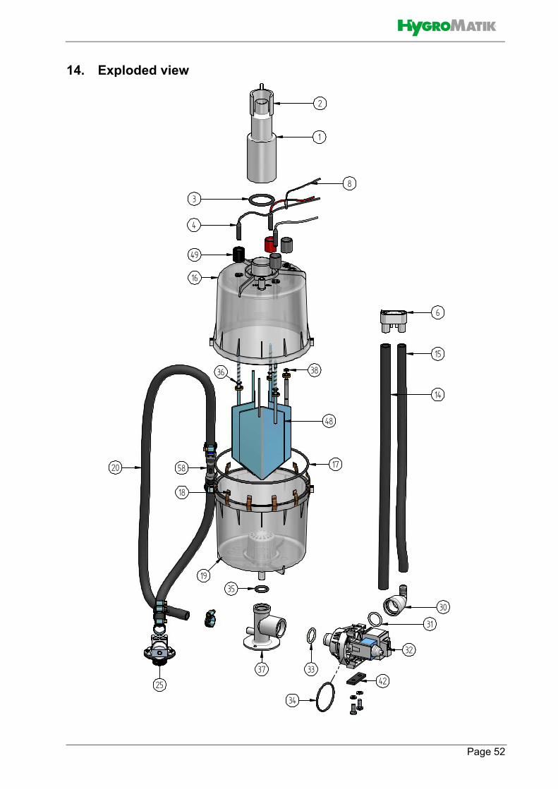
Page 52
14. Exploded view
��
�
��
�
�
�
�
�
��
�
�
��
��
��
��
��
�
�
�
�
�� ��
�
��
�
��
�
�
�
�
�
��
�
�
��
��
��
��
��
�
�
�
�
�� ��
�

Page 53
15. View of housingFLE05 - FLE30 FLE80
FLE40
FLE100, FLE130
FLE50, FLE65
70
56 57
70
56 57
70
56 575657
70
56 575657
70
56 57

100%
A Member of the group