Embed Size (px)
DESCRIPTION
Las cosechadoras de papas de marca Lockwood: manual del usuario partes, operacion, mantenimiento y seguridad.
Citation preview

502W & 5000 WINDROWEROWNER'S MANUAL
Manual PN 13767-00Rev. 0304 Companion to 13766-00

DisclaimerThis document is based on information available at the time of its publication. While efforts have been made to beaccurate, the information contained herein does not purport to cover all details or variations, nor to provide for everypossible contingency in connection with installation, operation, or maintenance. Features may be described herein whichare not present in all systems. Lockwood assumes no obligation of notice to holders of this document with respect tochanges subsequently made.
Lockwood assumes no responsibility for the accuracy, completeness, sufficiency, or usefulness of the information con-tained herein.
SPECIFICATIONS AND DESIGN ARE SUBJECT TO CHANGE WITHOUT NOTICE.
Lockwood is continually making improvements and developing new equipment. In doing so, we reserve the right to makechanges or add improvements to our product without obligation for equipment previously sold.
Because modification to this machine may affect the performance, function, and safety of its operation, no modificationsare to be made without the written permission of Lockwood. Part replacements should be with original equipment suppliedby Lockwood.
LOCKWOOD STATEMENT OF PRODUCT SAFETY
“As a manufacturer of specialized agricultural equipment, Lockwood, fully recognizes its responsibility of providing itscustomers products that perform to their expected use in a reasonably safe manner. Safety considerations shall be anintegral and high priority part of all engineering/design analysis and judgments involving Lockwood products. It is our statedpolicy that our products will be manufactured to comply with the safety standards specified by the American Society ofAgricultural Engineers, the National Electrical Code, The Society of Automotive Engineers, and/or any other applicablerecognized standards at the time manufactured. However, this statement should not be construed to mean that our productwill safeguard against a customer’s own carelessness or neglect in violating common safety practices specified in eachproduct’s manual, nor will we be liable for any such act.”
Copyright© 2001, Lockwood. All rights reserved. Produced and printed in the USA.
Trademark Information
Any trademarks not directly mentioned are also acknowledged.
PrefaceThis manual is intended for use with the “502W/5000 Windrower”
Is a trademark of the AmericanSociety of Agricultural Engineers(ASAE) and is so acknowledged.
Is a trademark of the Occupa-tional Safety & Health Adminis-tration (OSHA) and is so ac-knowledged.
Is a trademark of the NationalFire Protection Association(NFPA) and is so acknowledged.
Is a trademark of the Society of Au-tomotive Engineers (SAE) and is soacknowledged.
Is a trademark of the American Na-tional Standards Institute (ANSI) andis so acknowledged.
Is a trademark of the National Elec-trical code (NEC) and is so acknowl-edged.

i502W/5000 Windrower Owner Operator’s Manual
LOCKWOODLIMITED WARRANTY
Lockwood warrants for each original retail purchaser of new goods from Lockwood or a Lockwood Dealer, that suchgoods are at the time of delivery to such purchaser, free from defects in material and workmanship.
Electrical components operated on direct current (D.C.) circuits must be operated with respect to proper polarity andnot above or below the voltage specified by Lockwood. Electrical components operated on alternating current (A.C.) circuitsmust be operated at not more than five percent (5%) above or below that voltage and frequency specified by Lockwood.GOODS MUST BE ELECTRICALLY WIRED AND GROUNDED ACCORDING TO N.E.C. REQUIREMENTS AND INSPECTEDAND APPROVED BY LOCAL OR STATE INSPECTING AUTHORITIES.
Lockwood’s obligation under this warranty, unless otherwise specified is limited to (1) repairing, or at its option, (2)replacing with factory specified replacement parts, without cost, at a designated Lockwood Dealer, any parts which in Lockwood’sjudgment proved defective in material or workmanship within twelve (12) months after date of delivery to the original purchaser,unless the goods are purchased for commercial use, in which event the warranty period will be forty-five (45) days from thedate of delivery to the original purchaser. This warranty will not be valid if the goods are not assembled, operated and servicedin accordance with the Operator’s Manual.
SPECIAL PROVISIONSLockwood warrants its rod link chain against breakage in the link joint prior to the appearance of wear at such points.
Links which Lockwood has determined to be defective will be replaced F.O.B. factory, or the cost thereof credited to thepurchaser at Lockwood’s option.
GENERAL PROVISIONS - FIELD EQUIPMENTThe following general provisions are applicable to field equipment. The date of delivery shall be deemed to be the
date shown on the delivery and warranty registration form signed by the Purchaser and delivered to Lockwood (which is thedate of retail delivery).
No warranty shall apply to (1) normal maintenance, service or adjustments, (2) any Lockwood goods which shall havebeen repaired or altered in any way so as, in Lockwood’s judgment, to affect adversely their stability, operational characteris-tics or safety, nor which have been subject to misuse, negligence, accident, poor assembly or improper installation. Non-Lockwood manufactured products and/or components will be subject to warranties of their respective manufactures.
To make this warranty effective. (1) the purchaser’s Warranty Registration form furnished with each piece of equip-ment must be completed and on file at Lockwood factory, West Fargo, North Dakota prior to submitting any claims, (2) thewarranty claim must be completed and the parts claimed to be defective must accompany the completed warranty claim ifrequired.
FREIGHTDealer must prepay freight on warranty components returned to Lockwood. The components will be replaced F.O.B.
Factory.
LIMITATIONSThis Lockwood warranty is expressly in lieu of other warranties, expressed or implied, including without limitation,
warranties of MERCHANTABILITY AND FITNESS FOR A PARTICULAR PURPOSE, and any other obligation or liabilityincluding crop damage or loss of crops for liability for incidental or consequential damages on the part of Lockwood.
There are no warranties on used goods, USED GOODS ARE SOLD AS IS.
Lockwood shall not be liable or responsible in any way or to any extent for property damages, personal Injury, or deathresulting from the modification or alteration to Lockwood goods or from the purchaser’s failure to assemble, install, maintain,or operate the goods is accordance with the provisions of the Operator’s Manual
No statement, representation, agreement or understanding, oral or written, made by an agent, authorized Dealer, Lockwoodrepresentative or employee other than an officer of Lockwood in writing, which is not contained in the Warranty and Disclaimerwill be recognized or enforceable or binding upon Lockwood.
Any action for breach of any Lockwood warranty must be commenced within one year after date on which such causeof action occured.

PRE - DELIVERY CHECKLIST
This checklist is provided to identify items to be checked and adjusted if necessary by the dealer prior todelivery of a new machine
Check the following and adjust if necessary
The tire pressure is at the appropriate psi.
Set screws and keys are set and secure.
Hitch pins, spacers, and bushings for Category II & IIItractors are attached.
All points are properly lubricated. (See lubrication inthe service and maintenance section.)
Attachment of the hydraulic hoses and components iscorrect.
DELIVERY - CHECKLIST
Review the following with the customer at the time the unit is delivered
Review the operators manual, specifically the SafetyPrecautions.
Explain the importance of thoroughly reading and un-derstanding this manual.
Review the operation section.
Review the Service and maintenance section.
Be sure customer understands the location and func-tion of controls, safety decals and safety devices.
Explain adjustments for machine operation.
Explain the importance of proper lubrication and main-tenance.
Explain warranty to customer.
Both dealer and customer must sign the Delivery AndWarranty registration form.
ii 502W/5000 Windrower Owner Operator’s Manual
Machine matches sales order (correct serial numberand row spacing).
List machine’s serial number on warranty and registra-tion form.
No parts of the unit have been damaged during ship-ment. Check for such things as dents and loose ormissing parts.
The belt sheaves and roller chain sprockets are alignedand idlers are correctly spaced.
Roller chain and V-belt tensions are correct.
Bearing lock collars are secured and tightened in di-rection of rotation.
All nuts and bolts are tight.
Safety shields and safety decals are on and properlyplaced.
Wheel lug bolts are tightened to 100 ft./lbs torque.
The rod or belted chain pitches are matched with thesprockets.
Test hydraulic controls for proper operation.
Smooth hydraulic operation with no leaks.

HOHOHOHOHOW W W W W TTTTTO REAO REAO REAO REAO REACH USCH USCH USCH USCH US
iii502W/5000 Windrower Owner Operator’s Manual
Address Hours Telephone / Fax Number Email / Internet
Lockwood 237 12th St. NW P.O. Box 849 West Fargo, ND 58078-0849
Mon. - Fri. 8 A.M. to 5 P.M.
Central Time
For Parts and Service 1-800-247-7335
Fax: 701-282-9522
For Service: [email protected] For Parts: [email protected]
Visit our website: www.lockwoodmfg.com

1.0 INTRODUCTION ......................................................................................................................... 2
2.0 SAFETY .................................................................................................................................... 32.1 GENERAL SAFETY .................................................................................................................... 42.2 OPERATING SAFETY ................................................................................................................. 52.3 MAINTENANCE SAFETY ............................................................................................................ 52.4 HYDRAULIC SAFETY ................................................................................................................. 62.5 PTO (POWER TAKE-OFF) SAFETY ........................................................................................... 62.6 TRANSPORT SAFETY ................................................................................................................ 72.7 STORAGE SAFETY .................................................................................................................... 72.8 TIRE SAFETY ............................................................................................................................. 72.9 SAFETY DECALS ....................................................................................................................... 72.10 SAFETY DECAL LOCATIONS ..................................................................................................... 82.11 REFLECTORS........................................................................................................................... 132.12 SIGN-OFF FORM ...................................................................................................................... 15
3.0 OPERATION.............................................................................................................................. 163.1 TO THE NEW OPERATOR OR OWNER ................................................................................... 163.2 PRE-OPERATION CHECKLIST ................................................................................................. 163.3 MACHINE COMPONENTS ........................................................................................................ 173.4 INITIAL OPERATING PROCEDURE ........................................................................................... 18
3.4.1 PRE-START INSPECTION .............................................................................. 183.4.2 AFTER OPERATING FOR 2 HOURS .............................................................. 183.4.3 AFTER OPERATING FOR 10 HOURS ............................................................ 18
3.5 CONTROLS ............................................................................................................................... 193.6 OPERATING .............................................................................................................................. 20
3.6.1 ATTACHING IMPLEMENT TO TRACTOR ........................................................ 203.6.2 UNHOOKING IMPLEMENT FROM TRACTOR ................................................ 21
3.7 TRANSPORTING ....................................................................................................................... 223.7.1 TRANSPORTING THE WINDROWER.............................................................. 22
3.8 DIGGING .................................................................................................................................. 223.8.1 DIGGER NOSE .............................................................................................. 233.8.2 DIGGER BLADE ............................................................................................. 233.8.3 NOSE ROLLERS............................................................................................ 243.8.4 COULTERS .................................................................................................... 25
3.9 PRIMARY BELTED CHAINS ...................................................................................................... 263.10 SECONDARY BELTED CHAIN .................................................................................................. 263.11 OVERRIDE BELTED CHAIN ...................................................................................................... 273.12 REAR CROSS CONVEYOR ...................................................................................................... 273.13 REAR AXLE .............................................................................................................................. 283.14 REAR WHEELS ........................................................................................................................ 283.15 SLIP CLUTCHES ....................................................................................................................... 293.16 OPTIONS .................................................................................................................................. 30
3.16.1 VINE CHOPPER............................................................................................ 303.16.2 SNAPPING ROLLERS ................................................................................... 303.16.3 SNAPPER ROLLER ADJUSTMENT .............................................................. 303.16.4 SHAKERS ..................................................................................................... 303.16.5 THIRD COULTER ........................................................................................... 323.16.6 GAUGE WHEELS ......................................................................................... 323.16.7 ROLLER SCRAPERS .................................................................................... 32
iv 502W/5000 Windrower Owner Operator’s Manual
Section Description PageContents

502W/5000 Windrower Owner Operator’s Manual v
Section Description PageContents
3.17 OPERATING HINTS ................................................................................................................... 333.17.1 PREPARING SOIL AND CROP .................................................................... 333.17.2 ADVERSE CONDITIONS .............................................................................. 333.17.3 HARVESTING EFFICIENCY ......................................................................... 33
3.18 LOW DAMAGE OPERATING HINTS ......................................................................................... 343.18.1 DIGGER BLADES ......................................................................................... 343.18.2 BELTED CHAINS ........................................................................................... 34
3.19 STORAGE ................................................................................................................................. 353.19.1 POST SEASON MAINTENANCE ................................................................... 353.19.2 REMOVING FROM STORAGE/PRE-SEASON MAINTENANCE .................... 36
4.0 SERVICE AND MAINTENANCE ................................................................................................ 374.1 SERVICE .................................................................................................................................. 37
4.1.1 FLUIDS AND LUBRICANTS ............................................................................ 374.1.2 GREASING .................................................................................................... 374.1.3 SERVICE RECORD........................................................................................ 384.1.4 PTO SERVICE ............................................................................................... 39
4.2 MAINTENANCE ......................................................................................................................... 394.2.1 PREVENTIVE MAINTENANCE ....................................................................... 394.2.2 DRIVE CHAIN TENSION................................................................................. 404.2.3 DRIVE BELT TENSION ................................................................................... 404.2.4 BELTED CHAIN .............................................................................................. 414.2.5 REPAIR OF BELTED CHAIN .......................................................................... 414.2.6 CHANGING HYDRAULIC OIL FILTER ............................................................. 424.2.7 BLEEDING THE HYDRAULIC SYSTEM ......................................................... 43
5.0 TROUBLE SHOOTING ............................................................................................................... 445.1 WINDROWER TROUBLE SHOOTING ........................................................................................ 445.2 PREVENTABLE DAMAGE TO PTO DRIVE SHAFT .................................................................... 46
6.0 SPECIFICATIONS ..................................................................................................................... 476.1 GENERAL SPECIFICATIONS .................................................................................................... 476.2 CHAIN PITCH AND ROD CONFIGURATIONS ............................................................................ 486.3 CHAIN PATTERNS .................................................................................................................... 516.4 CHAIN COVERINGS ................................................................................................................. 53
6.4.1 PEGS .............................................................................................................. 536.4.2 FLIGHTS ......................................................................................................... 536.4.3 RUBBER COVER ............................................................................................ 546.4.4 PILLOW CUSHIONS........................................................................................ 556.4.5 C-FLEX ............................................................................................................ 566.4.6 EARS .............................................................................................................. 57
6.5 BOLT TORQUE.......................................................................................................................... 586.6 HYDRAULIC FITTING TORQUE ................................................................................................. 59


Page 1502W/5000 Windrower Owner Operator’s Manual
Always give your dealer the serial number of your Lockwood 502W or 5000 Windrower when ordering parts, requestingservice or other information.
The serial number decal is located on the right side of the machine near the hydraulic control bank (See Fig. #1). Pleasemark the number in the space provided for easy reference. Record the serial number on the Delivery And WarrantyRegistration form and on this page of your manual.
REPLACEMENT PARTS
Use only genuine Lockwood replacement parts to repair the machine. Your Lockwood Dealer offers Lockwood replacementparts. To obtain prompt, efficient service, remember to give the Dealer the correct part description and serial number of themachine.
Serial # ________________________
Figure #2 Serial number decal
YXXXXX
SERIAL NUMBER LOCATION
Figure #1 Serial number decal location

Page 2 502W/5000 Windrower Owner Operator’s Manual
1.0 INTRODUCTION
Congratulations on your choice of a new Lockwood 502W or 5000 Windrower to complement your farming operation. Thisequipment has been designed and manufactured to meet the needs of a discerning agricultural industry for the efficientdigging and windrowing of potatoes.
Safe, efficient, and trouble free operation of your windrower requires that you and anyone else who will operate or maintainthe machine, read and understand the Safety, Operation, Maintenance, and Trouble Shooting information contained withinthe Operator’s Manual. Check each item referred to and acquaint yourself with the adjustments required to obtain efficientoperation.
This manual covers only the 502W or 5000 Windrowers manufactured by Lockwood. The manual covers and explainsdifferences where appropriate. Use the Table of Contents as a guide to locate required information.
Keep this manual handy for frequent reference and to pass on to new operators or owners. Call your Lockwood Dealer ordistributor if you need assistance, information, or additional copies of the manuals.
Many people have worked on the design, production, and delivery of this machine. They have used the highest quality ofmaterials and workmanship. The manual’s information derives from the knowledge, study, and experience of these peoplethrough years of manufacturing specialized farming machinery.
The machine’s performance depends on proper maintenance and adjustment. Even if you are an experienced operator ofthis or similar equipment, we ask that you read the operator’s manual before running the machine. Keep the manual handyfor future reference. Lockwood has carefully prepared, organized, and illustrated this manual to assist you in finding theinformation you need. Your Lockwood Dealer will be happy to answer any further questions you may have.
OPERATOR ORIENTATION - The directions left, right, front, and rear, as mentioned throughout the manual, are as seenfrom the driver’s seat of the tractor and facing in the direction of travel.

Page 3502W/5000 Windrower Owner Operator’s Manual
This Safety Alert Symbol meansATTENTION! BECOME ALERT!YOUR SAFETY IS INVOLVED!
The Safety Alert symbol identifies importantsafety messages on the Lockwood 502W or5000 Windrower and in the manual. When yousee this symbol, be alert to the possibility ofpersonal injury or death. Follow the instruc-tions in the safety message.
Accidents Disable and KillAccidents CostAccidents Can Be Avoided
3 Big Reasons
SIGNAL WORDS:
Note the use of the signal words DANGER, WARN-ING, CAUTION, IMPORTANT and NOTE with thesafety messages. The appropriate signal word for eachmessage has been selected using the following guide-lines:
2.0 SAFETYSAFETY ALERT SYMBOL
Why is SAFETY important to you?
DANGER - Indicates an imminently hazardoussituation that, if not avoided, will re-sult in death or serious injury. Thissignal word is to be limited to the mostextreme situations, typically for ma-chine components that, for functionalpurposes, cannot be guarded.
WARNING - Indicates a potentially hazardous situ-ation that, if not avoided, could resultin death or serious injury, and includeshazards that are exposed whenguards are removed. It may also beused to alert against unsafe practices.
CAUTION - Indicates a potentially hazardous situ-ation that, if not avoided, may result inminor or moderate injury. It may alsobe used to alert against unsafe prac-tices.
IMPORTANT- Follow instructions to ensure properinstallation/operation of equipment.
NOTE - General statements to assist thereader

Page 4 502W/5000 Windrower Owner Operator’s Manual
2.0 SAFETY
The responsibility for SAFE operation and maintenance ofyour Lockwood 502W or 5000 Windrower rests on YOU.YOU must ensure that those who will operate, maintain orwork around this machine familiarize themselves with alloperating, maintenance, and SAFETY information containedin this manual. This manual discusses good safety prac-tices necessary to safely operate the Lockwood 502W or5000 Windrower.
Remember, YOU are the key to safety. Good safety prac-tices protects you and the people around you. Make thesepractices a working part of your safety program. Familiar-ize EVERYONE who operates this equipment with the rec-ommended operating and maintenance procedures andensure they follow all the safety precautions.You can pre-vent most accidents. Do not risk injury or death by ignoringgood safety practices.
• Lockwood 502W or 5000 Windrower owners must re-view operating instructions to operators or employeesbefore allowing them to operate the machine, and atleast annually thereafter per OSHA (Occupational Safetyand Health Administration) regulation 1928.57.
• The most important safety device on this equipment isa SAFE operator. The operator is responsible to readand understand ALL Safety and Operating instructionsin the manual and to follow them. You can avoid mostaccidents.
• A person who has not read and understood all operat-ing and safety instructions does not qualify to operatethe machine. An untrained operator exposes himselfand bystanders to possible serious injury or death.
• Do not modify the equipment in anyway. Unauthorizedmodification may impair the function and/or safety andcould affect the life of the equipment.
• Think SAFETY! Work SAFELY!
2.1 GENERAL SAFETY1. Read and understand the
Operator’s Manual and allsafety decals before oper-ating, maintaining, adjust-ing or unplugging theLockwood 502W or 5000Windrower.
2. Only trained persons shall operate the Lockwood502W or 5000 Windrower. An un-trained operator does not qualify tooperate the machine.
3. Have a first-aid kit available for useshould the need arise and know howto use it.
4. Provide a fire extinguisher for use incase of an accident. Store in a highlyvisible place.
5. Do not allow children, spectators or by-standers within hazard area of ma-chine.
6. Wear appropriate protective gear. This list includesbut is not limited to:
- A hard hat- Protective shoes
with slip resistantsoles
- Protectivegoggles
- Heavy gloves- Hearing protection- Respirator or filter mask
7. Wear suitable ear protectionfor prolonged exposure to ex-cessive noise.
8. Do not allow riders on theplanter.
9. Place all controls in neutral or off, stop tractor engine,set parking brake, remove ignition key, wait for allmoving parts to stop, then properly block machinebefore servicing, adjusting, repairing, or unplugging.
10. Review safety related items annually with all person-nel who will operate or maintain the Lockwood 502Wor 5000 Windrower.
WARNINGLockwood recommends that you always turn off the hy-draulic and electrical power to the Windrower hydraulicvalve and control box when towing the Windrower on theroad.

Page 5502W/5000 Windrower Owner Operator’s Manual
2.3 MAINTENANCE SAFETY1. Follow ALL the operating, maintenance, and safety in-
formation in the manual.
2. Support the machine withblocks or safety stands whenchanging tires or working be-neath it.
3. Follow good shop practices:•Keep service area cleanand dry.•Properly ground allelectrical outlets andtools.•Use adequate light forthe job at hand.
4. Use only tools, jacks and hoists of sufficient capacityfor the job.
5. Place all controls in neutral or off, stop tractor engine,set parking brake, remove ignition key, wait for all mov-ing parts to stop, then properly block machine beforeservicing, adjusting, repairing, or unplugging.
6. Before resuming work, install and secure all guards af-ter completing all maintenance work.
7. Relieve pressure from hydraulic circuit before servicingor disconnecting from tractor.
8. Clear the area of bystanders, especially small children,when carrying out any maintenance and repairs or mak-ing any adjustments.
9. Keep safety decals clean. Replace damaged or un-readable decals.
10. First-class maintenance is a prerequisite for the safestoperation of your machine. Perform maintenance, in-cluding lubrications, with the machine stopped and prop-erly blocked.
2.2 OPERATING SAFETY1. Install and secure all guards and shields before start-
ing or operating.
2. Clear the area of bystanders, especially small children,before starting the tractor.
3. Place all machine controls in neutral before startingthe tractor.
4. Keep hands, feet, hair and clothing away from all mov-ing and/or rotating parts.
5. Keep all hydraulic lines, fittings, and couplers tight andfree of leaks before and during use.
6. Clean reflectors and lights before transporting.
7. Review safety related items annually with all personnelwho will operate or maintain the windrower.
8. Be careful when operating on uneven terrain, or nearditches to avoid the potential of overturning the ma-chine.
9. Use only recommended tractor sizes with proper weightand equipment for operating the machine.
10. Never stand between the tractor and the machine whenthe tractor backs up for hookup.
11. Use the correct size hitch pin to prevent unhitching.
12. When backing up the machine, all persons must standaway from the back of the unit due to the operator’simpaired vision.
13. Be careful during field and transport operation not tocontact trees, power poles, and electrical lines withthe machine’s row marker. Electrocution can occurwithout direct contact.
14. After using agricultural chemical and seed treatments,thoroughly remove residues and deposits before stor-ing the machine. Refer to the section in this manualregarding chemical safety.
15. Shut the tractor off when connecting or disconnectingthe machine hydraulics.

Page 6 502W/5000 Windrower Owner Operator’s Manual
2.4 HYDRAULIC SAFETY
1. Always place all tractor hydraulic controls in neutralbefore disconnecting from tractor or working on hy-draulic system.
2. Keep all components in the hydraulic system in goodcondition and clean.
3. Relieve pressure before working on the hydraulic sys-tem.
4. Replace any worn, cut, abraded, flattened or crimpedhoses.
5. Do not attempt any makeshift repairs to the hydraulicfittings or hoses by using tape, clamps or cements.The hydraulic system operates under extremely high-pressure. Such repairs will fail suddenly and create ahazardous and unsafe condi-tion.
6. Wear proper hand and eye pro-tection when searching for ahigh-pressure hydraulic leak.Use a piece of wood or card-board as a backstop instead of hands to isolate andidentify a leak.
7. If injured by a concentratedhigh-pressure stream of hydrau-lic fluid, seek medical attentionimmediately. Serious infectionor toxic reaction can developfrom hydraulic fluid piercing the skin surface.
8. Before applying hydraulic flow to the system, tightenall components and check for damaged lines, hoses,and couplings.
• Think SAFETY! Work SAFELY!
2.5 PTO (POWER TAKE-OFF)SAFETY
1. Keep bystanders, especially children, away from driveshafts.
2. Be extremely careful when working around PTOshafts, drivelines, or other rotating shafts.
3. Do not remove ormodify protectiveshields or guards.
4. Do not stepacross a PTO or driv-eline or use it as astep.
5. Keep guards andshields in place at alltimes while operating.
6. Replace all damaged or missing parts or shields withthe correct original manufacturer’s parts.
7. Grease, clean, and maintain PTO components ac-cording to original manufacturer’s specifications andinformation in this manual.
8. Operator must wear fairly tight clothing. Never wearloose-fitting jackets, shirts, or pants when workingaround the drive shafts. Tie long hair back or putunder a cap.
9. Keep hydraulic hoses, electric cords, chains, andother items from contacting the drive shafts.
10. Do not clean, lu-bricate, or adjust thedrive shafts with thePTO engaged and thetractor running.

Page 7502W/5000 Windrower Owner Operator’s Manual
2.7 STORAGE SAFETY
1. Store the unit in an area away from human activity.
2. Do not permit children to play on or around the storedmachine.
3. Store the unit in a dry, level area.
2.9 SAFETY DECALS
1. Keep safety decals clean and legible at all times.
2. Replace missing or illegible safety decals.
3. Replaced parts that displayed a safety decal shouldalso display the current decal.
4. When replacing decals, place back in original location.
5. Safety decals are available from your Dealer or the fac-tory.
How to Install Safety Decals:
• Clean and dry the installation area.
• Be sure temperature is above 50°F (10°C).
• Decide on the exact position before you remove thebacking paper.
• Remove the smallest portion of the split backing paper.
• Align the decal over the specified area and carefullypress the small portion with the exposed sticky back-ing in place.
• Slowly peel back the remaining paper and carefullysmooth the remaining portion of the decal in place.
• Pierce small air pockets with a pin and use a piece ofdecal backing paper to smooth out the decal.
2.8 TIRE SAFETY
1. Failure to follow proper procedures when mounting atire on a wheel or rim can produce an explosion whichmay result in serious injury or death.
2. Do not attempt to mount a tire unless you have theproper equipment and experience to do the job.
3. Have a qualified tire dealer or repair service performrequired tire maintenance.
1. Comply with all local regulations regarding transport-ing equipment on public roads and highways.
2. Ensure the SMV (Slow Moving Vehicle) emblem andall the lights and reflectors required by the localhighway and transport authorities are in place, areclean and can be seen clearly by all overtaking andoncoming traffic. Add extra lights or pilot vehicleswhen transporting at night or during periods of lim-ited visibility.
3. Ensure that the machine securely attaches to thetractor and all retainer pins are installed.
4. Do not allow riders on any part of the machine duringtransportation.
5. Towing speed should not exceed 25 MPH (40 km/h)due to farm rated tires and wheels. Reduce speedon rough roads and surfaces.
6. Always use hazard warning flashers on tractor whentransporting unless prohibited by law.
7. Be careful when transporting on public highways orroads.
8. Towing vehicle should weigh at least twice as muchas the towed machine.
9. Exercise extra caution in keeping the towing vehicleand the machine under control when going down longand/or steep grades.
10. Be careful during field and transport operation not tocontact trees, power poles, and electrical lines withthe machine’s row marker. Electrocution can occurwithout direct contact.
2.6 TRANSPORT SAFETY

Page 8 502W/5000 Windrower Owner Operator’s Manual
REMEMBER - If Safety Decals have been damaged, removed, become illegible or parts replaced without safety decals,apply new decals. The manufacturer or an authorized dealer will have new decals available.
2.10 SAFETY DECAL LOCATIONS
The pictures below show the types of safety decals and their locations on the equipment. Good safety requires that youfamiliarize yourself with the various safety decals, the type of warning and the area, or particular function related to the areasthat will require your SAFETY AWARENESS.
• Think SAFETY! Work SAFELY!
Fig. #3 Safety decal locations
Part # 0732-0383-00
CHAQUE INDICE ICI EST EN ANGLAIS. PROCUREZVOUS DESTRANSDUCTIONS EXACTES AVANT D'OPERER CETTE MACHINE.UNE MANQUE DE COMPRENDRE COMPLETEMENT ET DE SECONFORMER A CHAQUE INSTRUCTION PEUT ABOUTIR A UNEBLESSURE SERIEUSE OU FETALE.
LAS INSTRUCCIONES QUE APARECEN EN VARIAS PARTES DE ESTAMAQUINA ESTAN IMPRESAS EN IDIOMA INGLES. OBTENGA UNATRADUCCION CORRECTA ANTES DE OPERARLA. ATENTAR SU USOSIN CONOCER SU FUNCIONAMIENTO O NO SEGUIR FIELMENTE LASINSTRUCCIONES PUEDE CAUSAR HERIDAS GRAVES O MORTALES.
ALL DECALS ON THIS MACHINE ARE IN ENGLISH. OBTAIN ACCURATE TRANSLATION PRIOR TO OPERATING THIS MACHINE.FAILURE TO COMPLETELY UNDERSTAND AND COMPLY WITH ALLINSTRUCTIONS MAY RESULT IN SEVERE OR FATAL INJURY.
WARNING PRECAUCION ATENTION
Part # 0732-0231-00
B
A
WARNINGPower driven machinery.Can cause severe injury.Disconnect power before servicing.Keep hands, feet, clothing away from powerdriven parts.Do not run machine until all shields are in place.Read operator’s manual before servicing.

Page 9502W/5000 Windrower Owner Operator’s Manual
2.10 SAFETY DECAL LOCATIONS
The pictures below show the types of safety decals and their locations on the equipment. Good safety requires that youfamiliarize yourself with the various safety decals, the type of warning and the area, or particular function related to the areasthat will require your SAFETY AWARENESS.
• Think SAFETY! Work SAFELY!
D
CAUTION
injury or machineCan cause severeLOW SPEED TIRE
10 m.p.h.Do not exceed
damage.
F
Part # 0732-0371-00
C
Part # 0732-0525-00
Fig. #6 Safety decal locations
Fig. #4 Safety decal locations
Can cause serious injury or death.HIGH PRESSURE OIL
Located on all hydraulic cylinders. Part # 0732-0631-00
Fig. #5 Safety decal locations
REMEMBER - If Safety Decals have been damaged, removed, become illegible or parts replaced without safety decals,apply new decals. The manufacturer or an authorized dealer will have new decals available.

Page 10 502W/5000 Windrower Owner Operator’s Manual
2.10 SAFETY DECAL LOCATIONS
The pictures below show the types of safety decals and their locations on the equipment. Good safety requires that youfamiliarize yourself with the various safety decals, the type of warning and the area, or particular function related to the areasthat will require your SAFETY AWARENESS.
• Think SAFETY! Work SAFELY!
WARNING“Guards and shields are removed for illustrativepurposes only; do not operate without guardsand shields in place and functioning.
WARNING
place while machineis running.
Can cause severeEXPOSED DRIVE
Keep all shields in
injury.
H
Part # 0732-0512-00
Fig. #9 Safety decal locations
Fig. #8 Safety decal locations
G
Part # 0732-0575-00
CAUTION
Shut off power beforeremoving shields.
Can cause severeMOVING DRIVESinjury.
Fig. #7 Safety decal locations
REMEMBER - If Safety Decals have been damaged, removed, become illegible or parts replaced without safety decals,apply new decals. The manufacturer or an authorized dealer will have new decals available.

Page 11502W/5000 Windrower Owner Operator’s Manual
2.10 SAFETY DECAL LOCATIONS
The pictures below show the types of safety decals and their locations on the equipment. Good safety requires that youfamiliarize yourself with the various safety decals, the type of warning and the area, or particular function related to the areasthat will require your SAFETY AWARENESS.
• Think SAFETY! Work SAFELY!
Fig. #10 Safety decal location
Fig. #11 Safety decal location
0732-0585-00
DANGERCan cause severe
ends of driveline.Securely attach bothshields in place.Keep all driveline
injury or death.
J
Part # 0732-0511-00
Keep all driveline
driveline.
shields in place.Securely attachboth ends of
Can cause severeinjury or death.
DANGERI
Part # 0732-0585-00
Fig. #12 Safety decal locations (Decal “J” is applied to both sides)
REMEMBER - If Safety Decals have been damaged, removed, become illegible or parts replaced without safety decals,apply new decals. The manufacturer or an authorized dealer will have new decals available.

Page 12 502W/5000 Windrower Owner Operator’s Manual
2.10 SAFETY DECAL LOCATIONS
The pictures below show the types of safety decals and their locations on the equipment. Good safety requires that youfamiliarize yourself with the various safety decals, the type of warning and the area, or particular function related to the areasthat will require your SAFETY AWARENESS.
• Think SAFETY! Work SAFELY!
Fig. #14 Safety decal locationFig. #13 Safety decal location (Note: Applied to both sides)
K
Part # 0732-0570-00 (Both sides of hitch)Part # 0732-0539-00
P
injury or death.Can cause severeMOVING COULTER
REMEMBER - If Safety Decals have been damaged, removed, become illegible or parts replaced without safety decals,apply new decals. The manufacturer or an authorized dealer will have new decals available.

Page 13502W/5000 Windrower Owner Operator’s Manual
REMEMBER - If reflectors have been damaged, removed, become illegible or parts replaced without safety reflectors, newreflectors must be applied. New reflectors are available from the manufacturer or an authorized dealer.
Part # 0733-0034-00
Figure #15 Reflector Location
2.11 REFLECTORS
The pictures below show types of reflectors and locations on the equipment. The owner is responsibile to know the lightingand marking requirements of the highways used and to install and maintain the equipment to provide compliance with theapplicable regulations. Add extra lights and or use escort vehicles when transporting during periods of limited visibility.

Page 14 502W/5000 Windrower Owner Operator’s Manual
REMEMBER - If reflectors have been damaged, removed, become illegible or parts replaced without safety reflectors, newreflectors must be applied. New reflectors are available from the manufacturer or an authorized dealer.
Fig. #18 Reflector decal location Fig. #19 Reflector decal location
Fig. #16 Reflector decal location (Note: To be applied to both sides) Fig. #17 Reflector decal locations
WARNINGGuards and shields are removed for illustrativepurposes only; do not operate without guardsand shields in place and functioning.
Part # 14432-00 (orange) Part # 0732-0093-00 (red)
NML
Part # 0732-0092-00 (amber)
2.11 REFLECTORS
The pictures below show types of reflectors and locations on the equipment. The owner is responsibile to know the lightingand marking requirements of the highways used and to install and maintain the equipment to provide compliance with theapplicable regulations. Add extra lights and or use escort vehicles when transporting during periods of limited visibility.

Page 15502W/5000 Windrower Owner Operator’s Manual
2.12 SIGN-OFF FORM
Lockwood follows the general Safety Standards specified by the American Society of Agricultural Engineers (ASAE) andthe Occupational Safety and Health Administration (OSHA). Anyone who will operate and/or maintain the equipment mustread and clearly understand ALL Safety, Operating and Maintenance information presented in this manual.
Do not operate or allow anyone else to operate this equipment until such information has been reviewed. Annually reviewthis information before the season start-up.
Make these periodic reviews of SAFETY and OPERATION a standard practice for all of your equipment. An untrainedoperator is unqualified to operate this machine.
A sign-off sheet is provided for your record keeping to show that all personnel who will work with the equipment have readand understood the information in the Operator’s Manual and have been instructed in the operation of the equipment.
SIGN-OFF FORM
DATE EMPLOYEES SIGNATURE EMPLOYERS SIGNATURE

Page 16 502W/5000 Windrower Owner Operator’s Manual
The Lockwood Potato Windrower is designed to efficientlyand rapidly dig and windrow potatoes. The tractor PTO andhydraulics provide the power. Be familiar with the machinebefore starting.
The owner/operator is responsible to read this manual andto train all other operators before they start working with themachine. In addition to the design and configuration of equip-ment, hazard control and accident prevention depend uponthe awareness, concern, and prudence of personnel involvedin the operation, transport, maintenance and storage ofequipment or in the use and maintenance of facilities.
Follow all safety instructions exactly. Safety is everyone’sbusiness. By following recommended procedures, a safeworking environment is provided for the operator, bystand-ers and the area around the work site. Untrained operatorsdo not qualify to operate the machine.
Many features incorporated into this machine come fromsuggestions made by customers like you. Read this manualcarefully to learn how to operate the machine safely andhow to set it to provide maximum efficiency. By followingthe operating instructions in conjunction with a good main-tenance program, your Lockwood Windrower will providemany years of trouble-free service.
3.1 TO THE NEW OPERATOR OROWNER
3.2 PRE-OPERATION CHECKLIST
Efficient and safe operation of the Lockwood Windrower re-quires that each operator reads and understands the oper-ating procedures and all related safety precautions outlinedin this section. This manual provides a pre-operation check-list for the operator. To maintain personal safety and a goodmechanical condition, follow this checklist.
Before operating the windrower, and each time thereafter,check off the following areas:
1. Service the machine per the schedule outlined in theMaintenance section.
2. Use only a tractor of adequate power and specificationsto operate the windrower.
3. Check that all guards are installed, secured and func-tioning as intended. Do not operate with missing or dam-aged shields.
4. Ensure that the machine properly attaches to the tractorand that mechanical retainers, such as Klik pins are in-stalled.
5. Check the drives for entangled material.
6. Check the chains and sprockets for proper tension andalignment. Adjust as required.
7. Visually inspect the hydraulic system for leakage, loosefittings, and damaged hoses. Tighten fittings, replacedamaged components and wipe up leaked or excesshydraulic fluid.
3.0 OPERATION

Page 17502W/5000 Windrower Owner Operator’s Manual
3.3 MACHINE COMPONENTS
The Lockwood Potato Windrower uses a digger section to bring the potatoes up from the ground onto the primary beltedchains. The primary belted chains then deliver the potatoes onto the secondary belted chain and the override belted chainwhere the vines are separated from the potatoes. The potatoes are then transported to the rear cross conveyor, whichplaces the potatoes in a windrow. The vines are then carried out the back of the machine.
A. MAIN FRAMEB. DIGGER NOSEC. DIGGER BLADESD. PRIMARY BELTED CHAINE. OVERRIDE BELTED CHAINF. SECONDARY BELTED CHAING. REAR CROSS BELTED CHAINH. COULTERI. HITCHJ. PRIMARY DRIVELINEK. REAR WHEELSL. SNAPPER ROLLERSM. MANUAL HYDRAULIC SHAKER
Figure #20

Page 18 502W/5000 Windrower Owner Operator’s Manual
3.4 INITIAL OPERATING PROCEDURE
Although no operational restrictions exist for the LockwoodPotato Windrower when used for the first time, Lockwoodrecommends that the following mechanical items bechecked:
3.4.1 PRE-START INSPECTION
1. Read the Operator’s Manuals.
2. Tighten wheel bolts to 100 ft./lbs. torque.
3. Check tires and inflate to their specifiedpressure.
4. All hydraulic lines and electrical harnesses should notcontact moving parts. Clip, tape, or tie all componentssecurely in place.
5. Check that all guards are installed and secured.
6. Install and tighten all required nuts and bolts to theirspecified torque.
3.4.2 AFTER OPERATING FOR 2 HOURS
1. Re-torque all the wheel bolts.
2. Re-torque all other fasteners and hardware.
3. Check that all safety decals are installed and legible.Apply new decals if required.
4. Check for any pinched, crimped, or rubbing hoses.Reroute as required.
5. Check that the wiring harness is not being pinched,crimped, or rubbing. Reroute as required.
6. Check the tension and alignment of all drive chains.Adjust as required.
3.4.3 AFTER OPERATING FOR 10 HOURS
1. Re-torque all wheel bolts, fasteners and hardware.
2. Check that all guards are installed, secured and func-tioning as intended. Do not operate with missing ordamaged shields.
3. Check safety decals. Install new ones if required.
4. Check the routing of hydraulic lines and the wiringharness. Reroute as required to prevent pinching,crimping, binding, or rubbing.
5. Go to the normal servicing and maintenance sched-ule as defined in the Maintenance Section.

Page 19502W/5000 Windrower Owner Operator’s Manual
3.5 CONTROLS
Lockwood recommends that all operators review this sec-tion of the manual to familiarize themselves with the loca-tion and function of all machine controls before starting.Some machines may vary slightly due to custom or op-tional features.
Electrical controls (Refer to Fig. #21 for the label designa-tions of the following descriptions):
A- Coulter master: Moves both the right and the leftcoulters simultaneously up or down (green).
B- Coulter left: Moves the left coulter up or down (green).
C- Coulter right: Moves the right coulter up or down (green).
D- Speed: Adjusts the speed of the rear cross conveyor(blue). (optional)
E- Discharge: Changes the angle of the discharge up ordown (light blue).
F- Nose master: Moves both right and left digger nose si-multaneously up or down (yellow).
G- Nose left: Moves the left digger nose up or down (yel-low).
H- Nose right: Moves the right digger nose up or down (yel-low).
I- Steering: Changes the steering of the windrower wheelsleft and right (red).
J- Shaker: Moves the shakers up or down, or controls thespeed of the hydraulic shakers (gray).
COULTERMASTER
UP
DOWN
COULTERLEFT
DOWN
UP UP
COULTERRIGHT
DOWN DOWN
SPEED
UP UP
DOWN
DISCHARGE
MASTERNOSE
DOWN
UP
DOWN
NOSELEFT
UP
RIGHTNOSE
DOWN
UP
STEERING
SHAKER
DOWN
UP
RIGHTLEFT
CB
DE
F G H I J
BLANK
A
Fig. #21 Control box

Page 20 502W/5000 Windrower Owner Operator’s Manual
3.6 OPERATING
3.6.1 ATTACHING IMPLEMENT TO TRACTOR
Always place the Lockwood Harvester on a hard, dry sur-face free of obstacles and debris. When ATTACHING themachine to the tractor, follow this procedure.
1. Clear the area of bystanders, especially small children.
2. Make sure enough room and clearance exists awayfrom obstacles to safely back up to the windrower.
3. Back the tractor up slowly aligning the pintle hitch ofthe windrower with the tractor drawbar.
4. Jack up the hitch to clear the tractor drawbar.
5. Connect the hitch of windrower to the tractor and se-cure with appropriate hardware.
6. Check the level across the harvester’s main frame
7. If the windrower is not level, disconnect the windrowerfrom the tractor and adjust the pintle up or down. (Fig.#22).
8. Clean and grease the PTO shaft of the tractor and theimplement end of the driveline input connection.
Fig. #23 Attaching driveline to PTO of tractor
IMPORTANTFor maximum efficiency the machine must be level dur-ing operation.
WARNINGHeavy tongue weight can cause severe injury or death.Support the jack and tongue securely. Approximatetongue weight is 10,000 lbs.
9. Connect the driveline (See Fig. #23) to the tractor byrotating the locking collar and simultaneously pushingthe driveline onto the tractor PTO shaft. Properly at-tach the implement end of the driveline to the harvesterand tighten all bolts to their specified torque.
NOTEThe tractor PTO must be Ø1-3/4” - 20 spline or Ø1-3/8” -21spline.
NOTECheck shaft articulation and clearance zone! Jointarticulation of more than 70 to 80 degrees leads todamage. Contact between implement input drivelineand tractor or implement (e.g. three point hitch, drawbar,hitch pin, jacks, etc.) leads to damage. Do not usetractors that have a PTO connection point does notallow the implement input driveline to articulate fullywithout interference.
WARNINGCheck the length of the telescoping members to ensurethe driveline will not bottom out or separate when turningand/or traveling over rough terrain. The implement manu-facturer should only modify the length of the implementinput driveline.
Fig. #22 Adjust pintle hitch to level the windrower

Page 21502W/5000 Windrower Owner Operator’s Manual
IMPORTANTWhen engaging or disengaging the PTO after hookup,run the engine at low idle speed.
10. Route and connect the hydraulic lines of the windrowerto the tractor. Attach the main control valve and lines tothe tractor. (Check the tractor operator’s manual or askyour dealer for information on hookup to the tractor’shydraulic system.)
11. Mount the electric control box in the tractor cab.
12. Route and connect wiring harness from the windrowerto the electronic control box in the tractor cab.
13. Start the tractor, activate hydraulic control valve thenoperate all control switches to activate each hydraulicsystem. Extend each cylinder to its maximum length.Check the tractor hydraulic reservoir to replenish thehydraulic oil.
14. Raise and lower the machine a few times to be sureeverything is secure, tight, and functioning.
6. Stow wiring harnesses on the hitch.
7. Disconnect all hydraulic lines from the tractor and stowon the hitch. Be sure the ends remain clean and un-damaged.
8. Disconnect PTO (See Fig. #24) by rotating the lockingcollar and simultaneously pull implement input drivelineoff of PTO shaft.
9. Jack windrower hitch to clear tractor drawbar.
10. Place blocks or a stand under the front of the hitch forsupport.
11. Pull tractor slowly away from windrower.
3.6.2 UNHOOKING IMPLEMENT FROM TRAC-TOR
When UNHOOKING the machine from the tractor, followthis procedure.
1. Clear the area of bystanders, especially small children.
2. Select a level, dry area, free of debris.
3. Position the machine in the location desired.
4. Shut down tractor and relieve the pressure in all hydrau-lic circuits.
5. Disconnect power leads from electrical boxes.
WARNINGPlace all controls in neutral or off, stop tractor engine, setparking brake, remove ignition key, wait for all moving partsto stop, then properly block machine before servicing, ad-justing, unhooking, attaching, repairing, or unplugging.
Fig. #24 Unhooking PTO
3.6.1 ATTACHING IMPLEMENT TO TRACTOR (CONT’D)
This harvester control valve can be configured to operateas closed center or open center hydraulics. You canchange the control valve by changing the cartridges andplugs in the valve stack. See decal under valve stack coverfor instructions. For most tractors and harvesters withmotors, set the valve stack for open center, and set theflow of the valve stack from 2 to 3 gpm. Ask your dealerfor instructions.
NOTE

Page 22 502W/5000 Windrower Owner Operator’s Manual
3.7 TRANSPORTING
The Lockwood Potato Windrowers are designed to easilyand conveniently move from location to location. When trans-porting the machine, review and follow these instructions:
3.8 DIGGING
The nose and the belted chain have been designed to dothe most efficient lifting of any machine in the industry. Ifnecessary, you can make fine adjustments to provide foran efficient harvest.
WARNINGPlace all controls in neutral or off, stop tractor engine, setparking brake, remove ignition key, wait for all moving partsto stop, then properly block machine before servicing, ad-justing, unhooking, attaching, repairing, or unplugging.
3.7.1 TRANSPORTING THE WINDROWERWhen transporting the machine, follow this procedure:
1. Attach the windrower to the tractor by following the procedure in section 3.6 of the manual.
2. Towing speed should not exceed 25 MPH (40 km/h). Theratio of the tractor weight to the windrower weight playsan important role in defining acceptable travel speed. Thefollowing table summarizes the weight ratio to travel speed.
Table # 1 weight ratio to road speed
Travel Speed
Weight of fully equipped or loaded implement(s) relative to weight of towing machine
Up to 25 M.P.H. (40 km/h) 1 to 1, or less
Up to 10 M.P.H. (16 km/h) 2 to 1, or less
Do not tow More than 2 to 1

Page 23502W/5000 Windrower Owner Operator’s Manual
B. Semi point blade with rod (rock blades) (See Fig. #27):Use this blade in sandy or light soil where rocks maybe present. This blade has a wedge on the back edgethat pushes rocks down, diverting them from the beltedchain as it cycles around the front rollers.
C. Clod blades (See Fig. #28):This blade works best in heavier soil that may pro-duce clods on the windrower’s belted chains. Unlikethe semi point blades the clod blade is not sharp atthe point but has a 1” bar at the front edge of theblade. This blade breaks the soil and will not leavelarge clods going up the digger bed. Instead, theblade breaks the large clods into more manageablesmaller clods.
A. Semi point blades (See Fig. #26):This blade works best in sandy or light soil withoutclods. At the proper digging depth, the blade mustcut slightly deeper than the belted chain’s positionotherwise, excessive wear will occur on the primarybelted chains and rollers. The blade’s pitch shouldbe steep enough not to allow the potatoes to come incontact with the belted chain until they are carriedaway.
3.8.2 DIGGER BLADE
Blade angle can be changed by loosening the rear bolt ofthe blade mounting brackets and moving the bolts up ordown in one of the holes in the frame. (See Fig. #25).
Types of Digger blades:
Digger blades are available for narrow and wide digger noses.The narrow digger nose is used with row widths of 32” & 34”and the wide digger nose with row widths of 36”- 40”.
3.8 DIGGING
3.8.1 DIGGER NOSE
The digger nose height can be adjusted with the two 1” nutsat the top of the lifting rod. Loosen the top nut and turn thelower nut down to desired lift height. Lock the top nut downon the adjusting nut to complete your change.
NOT SHOWN: The lifting rod has a spring under the mountingbracket that will put downward pressure on the digger blade.By raising the digger nose, the nuts will increase the downpressure.
Fig. #26 Semi point blade
Fig. #27 Semi-point blade with rods (rock blade)
Fig. #28 Clod Blade
Fig. #25 Digger Nose Assembly
E. Combination blades (See Fig. #29):The windrower can use combination blades in a vari-ety of soil conditions, except light sandy soil. Combi-nation blades have a scoop in the middle of the rowwhere potatoes are present. This scoop harvests allthe potatoes, but doesn’t promote digging excess soilbetween rows.
Figure. #29 Combination Blades
The digger nose is raised and lowered by 2 hydraulic cylin-ders, one on each side of the nose. Each side of the nosecan be raised and lowered independently or as a unit, withthe control box in the tractor cab.

Page 24 502W/5000 Windrower Owner Operator’s Manual
Assuming the blade angle and nose roller relationship iscorrect, too much sag in the return side of the primary beltedchain can cause feed problems (See Fig. #32). Too muchsag causes the belted chain to drag along the ground, pull-ing soil back under the nose roller. The entry of this soil intothe crop flow pattern causes an obstruction. Dragging thebelted chain on the ground also greatly reduces chain life.
Properly adjusted (See Fig. #33), the digger blades will clearsoil away from the front of the belted chain. As the bladewears, adjust the nose rollers upward to a new setting torestore proper ground clearance with the blades. This givesyou the advantage of longer service life of the digger blades.
For the most effective action in heavy soil, set the noserollers slightly above the center line of the blades. This raisesthe soil as it passes over the blade onto the belted chain,causing a disintegrating action that begins soil breakup andseparation. Use the six holes located on the digger framewhen making this adjustment (see Figure #30).
3.8.3 NOSE ROLLERS
The nose rollers located at the forward end of the primary`belted chain can be adjusted up or down and forward orbackward by placing the nose roller bolt in the proper holesin the digger frame (see Figure #30). Make adjustments asneeded to change the nose roller position in relation to thedigger blades to meet varying soil conditions.
The relationship of the nose roller to the blade by soil typeswill affect the windrower’s efficiency and the life of the beltedchain. (See Fig. #30 through #33).
In loose soils, if the nose roller is set too high (See Fig.#31), the belted chain will push the soil forward and exposethe potatoes to the belted chain. The top of the blade shouldbe in line with the belted chain.
Fig. #32 Nose roller set low - dragging chain
Fig. #31 Nose roller set high - boiling potato damage
Fig. #33 Proper feed
3.8 DIGGING (CONT’D)
Figure #30 Nose Roller Adjustment

Page 25502W/5000 Windrower Owner Operator’s Manual
3.8 DIGGING
3.8.4 COULTERS
The coulters can be set on either side of the digger noseand nose wing. Three different types of blades are available.Larger diameter coulters help prevent boil out.
1) 24” notched coulters: These coulters work well in firmsoil to cut vines that may wrap around the digger nosewings. (See Figure #34).
2) 24” & 27” waffle coulters: These work best in sandysoil where the coulter may not turn as easily in thesoil. The waffle coulter, however, cannot run as closeto the nose wing as the straight coulter, increasingthe chance of wrapping (See Figure #35).
3) 24” Straight Coulter: The straight coulter is an all pur-pose coulter. The coulter will work in any soil type(See Figure #36).
Coulter Adjustment
The mounted coulters have heavy springs that allow adjust-ment (See Fig. #37) for the coulter to cross over stoneswithout causing harm to the disc or mounting frames.
To provide more downward pressure: Loosen the jam nutand tighten the adjustment nut.
To provide less downward pressure: Loosen the jam nutand loosen the adjustment nut.
After adding pressure to the coulters, raise them with thehydraulics using the UP switch on the control box. Be care-ful as you near the top of the cycle to be sure the coulterdisc is not hitting the main frame of the windrower. If thedisc hits the frame, lower it using the adjusting nut to aposition that does not allow it to hit the frame.
After positioning the coulters, check the length of the shaft.The excess shaft could snag and drag vines from the nextrow. If desired the excess shaft length can be cut off to avoiddragging vines.
The coulters serve 3 main functions:
1. Cutting the vines to prevent wrapping on the front edgeof the wing.
2. Cutting the soil profile to help funnel material into thedigger nose.
3. Prevent drifting on hills.
The coulters are raised with 2 hydraulic cylinders and canbe raised simultaneously or individually.
NOTERaise the coulters before turning.
Fig. #37 Coulter Adjustment
Fig. #35 Waffle Coulter
Fig. #36 Straight Coulter
Fig. #34 Notched Coulter

Page 26 502W/5000 Windrower Owner Operator’s Manual
3.9 PRIMARY BELTED CHAINS
The primary belted chain is located in the digger section ofthe windrower (See Fig. #38). The belted chain is either fullwidth or split and is made up of ½” (13mm) rods. The rodcomes in various patterns and pitches designed for differentsoil conditions.
See Sec 6.2 and 6.3 for rod and pattern recommendations.
3.10 SECONDARY BELTED CHAINS
The digger (primary) section of the harvester places the po-tatoes on the override and secondary belted chains (SeeFig. #39). The potato has a small drop from the diggersection of the windrower to the secondary belted chain. Arubber cushion on the override and secondary belted chainsprevents the potatoes from bruising.
The secondary belted chain carries the potatoes onto therear cross conveyor.
If excess dirt exists, have the rollers positioned so that theyare touching the rods, as opposed to underneath the belt.This shakes the belted chain and allows excess dirt to fallthrough the belted chain, without damaging the potatoes.
The secondary belted chain discharges to two locations.One half of the belted chain discharges to the front of therear cross and the other to the rear. This allows the pota-toes to spread out on the rear cross conveyor.
Fig. #38 Primary Belted Chain
Fig. #39 Secondary Belted Chain
Page 27502W/5000 Windrower Owner Operator’s Manual
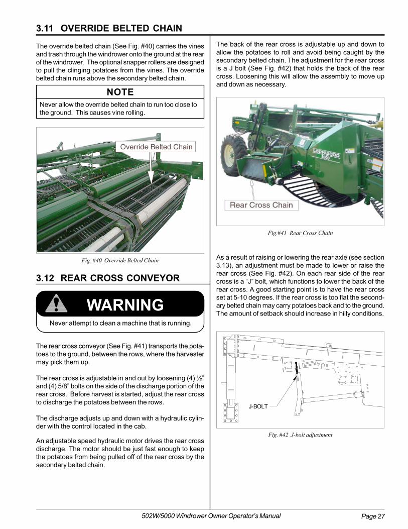
An adjustable speed hydraulic motor drives the rear crossdischarge. The motor should be just fast enough to keepthe potatoes from being pulled off of the rear cross by thesecondary belted chain.
WARNINGNever attempt to clean a machine that is running.
The rear cross conveyor (See Fig. #41) transports the pota-toes to the ground, between the rows, where the harvestermay pick them up.
The rear cross is adjustable in and out by loosening (4) ½”and (4) 5/8” bolts on the side of the discharge portion of therear cross. Before harvest is started, adjust the rear crossto discharge the potatoes between the rows.
The discharge adjusts up and down with a hydraulic cylin-der with the control located in the cab.
3.12 REAR CROSS CONVEYOR
3.11 OVERRIDE BELTED CHAIN
The override belted chain (See Fig. #40) carries the vinesand trash through the windrower onto the ground at the rearof the windrower. The optional snapper rollers are designedto pull the clinging potatoes from the vines. The overridebelted chain runs above the secondary belted chain.
NOTENever allow the override belted chain to run too close tothe ground. This causes vine rolling.
Fig.#41 Rear Cross Chain
Fig. #40 Override Belted Chain As a result of raising or lowering the rear axle (see section3.13), an adjustment must be made to lower or raise therear cross (See Fig. #42). On each rear side of the rearcross is a “J” bolt, which functions to lower the back of therear cross. A good starting point is to have the rear crossset at 5-10 degrees. If the rear cross is too flat the second-ary belted chain may carry potatoes back and to the ground.The amount of setback should increase in hilly conditions.
The back of the rear cross is adjustable up and down toallow the potatoes to roll and avoid being caught by thesecondary belted chain. The adjustment for the rear crossis a J bolt (See Fig. #42) that holds the back of the rearcross. Loosening this will allow the assembly to move upand down as necessary.
Fig. #42 J-bolt adjustment
J-BOLT

Page 28 502W/5000 Windrower Owner Operator’s Manual
3.13 REAR AXLE
The rear axle of the windrower (See Fig. #43) is adjustableup and down. The higher the back of the windrower is raisedthe more dirt will be separated. However, this increases thechances of skinning potatoes as they climb on the beltedchain. If this happens, decrease the PTO speed and in-crease the ground speed or lower the rear of the windrower.
The adjustment on the rear axle allows a total of 8” up anddown movement. The machine is shipped in its lowest posi-tion.
To raise the machine turn the 2 ratchet jacks (See Fig. #43)at the same time. When you are at the desired height checkthe rear frame with a tape measure (distance between up-per and lower tubes) to be sure they are at the same height.
3.14 REAR WHEELS
The rear wheels are adjustable to fit a variety of row spac-ings ranging from 32” - 40”. To adjust the rear wheels, followthese steps:
1. Jack the back axle off the ground to remove weight off thetires.
2. Remove the axle bolts that hold the adjustable axle inplace.
3. Remove the two bolts in the tie rod.
4. Remove the wheel bolts from both wheels.
5. Pull out the adjustable axle until it is placed at the de-sired row spacing.
Be advised that raising the rear of the machine up will flattenthe rear cross conveyor. See section 3.12 for adjustmentinstructions.
Fig. #43 Ratchet Jack
6. Adjust the tie rod in or out until the desired row spacingis set. The front of the tires should be set 1” narrowerthan the rear, measured at the center of the front and rearof the tires.
7. Place all bolts back into their respective holes.
8. To fine tune the tie rod setting, adjust the jam nut.
9. Remove the bolts from the metal flange that connects thesteering cylinder to the cylinder mount. The cylinder mounthas pre-drilled holes that fit different row spacing set-tings. Set the steering cylinder in accordance with youraxle row spacing setting.
10. Adjust the steering indicator rod so that the rod lines upwith the middle of the R/L decal (see Figure #46 on thenext page).
Figure #44 Rear Wheel Axle Adjustment (Left Side)
Figure #45 Rear Wheel Axle Adjustment (Right Side)

Page 29502W/5000 Windrower Owner Operator’s Manual
NOTICESLIP CLUTCHES
Adjustment
0732-0470-00
Attention
A.) Tighten bolts until head contacts spring.B.) Tighten two full turns beyond initial contact.C.) Test by running machine under load.D.) Readjust as necessary to carry load by tightening in 1/4 turn increments.E.) Do not over tighten: Overtightening may damage drive train or conveyors.
After long periods of no use, rust and weather can causeclutch to stick. Release all spring tension and allow clutch to slip. Readjust as specified above.
3.15 SLIP CLUTCHESA slip clutch protects the primary, secondary, and overideconveyors on the windrower (See Fig. #47). The factory as-sembles these clutches and you MUST adjust them in thefield to meet load conditions.
NOTEDo not overtighten the slip clutch. After long periods ofno use, rust and weather can cause the slip clutch tostick. Annually service the slip clutch by releasing thetension on the springs and allow the clutch to slip. Re-adjust the slip clutch as described previously.
WARNINGPlace all controls in neutral or off, stop tractor engine,set parking brake, remove ignition key, wait for all mov-ing parts to stop, then properly block machine beforeservicing, adjusting, unhooking, attaching, repairing, orunplugging.
WARNINGFailure to properly adjust the clutches can cause down-time due to broken chains or cause serious injury.
To adjust the slip clutch, turn each bolt clockwise until thehead of the bolt contacts the spring. Tighten each bolt twofull turns and test. If further adjustment is needed, turn thebolt 1/4 of a turn. The clutch should be adjusted so that itdoes not slip under normal operating conditions.
Do not turn the bolt more than 1/4 of a turn withouttesting the slip clutch.
Fig. #47 Slip Clutch
WARNING“Guards and shields are removed for illustrativepurposes only; do not operate without guardsand shields in place and functioning.
3.14 REAR WHEELS
Q
SLIP CLUTCHSIDE VIEW
BOLT
TIGHTEN UNTILBOLT HEAD CONTACTS
SPRING
SPRING
THEN TIGHTEN BOLTS TWO FULL TURNS USING AN
ALTERNATING CROSS PATTERN
SLIP CLUTCHFRONT VIEW
Fig. #48 Slip Clutch
Figure #46 R/L Decal

Page 30 502W/5000 Windrower Owner Operator’s Manual
3.16 OPTIONS
3.16.1 VINE CHOPPER
The vine chopper is mounted to the windrower frame in frontof the rear wheels and in back of the override discharge. Thelifting action of the rotor picks the vines off the override beltedchain, carries them into the stationary knives and cuts theminto 4- to 6-inch pieces. The vine chopper eliminates blow-ing of heavy vines into undug rows, vine wrap on truck drivelines, and one tractor and disk operation.
The components are designed for long life with heat-treatedflails running on hardened bushings. The stationary knivesare also heat-treated. The vine chopper is powered througha drive line equipped with an overrunning clutch and beltdrive. The clutch will “free wheel” when the tractor PTO isdisengaged. The clutch will pick up smoothly and in combi-nation with the belt drive, eliminating shock loads to thedrive assembly. The rotor is balanced to eliminate vibrationduring operation. The desired operating speed of rotation ofthe vine chopper is 1150 R.P.M.
In extreme wet conditions, it may be necessary to reversethe stationary knives to keep the chopper from plugging.When it is reversed, the chopper will still shred vines, how-ever the pieces will be larger.
3.16.3 SNAPPER ROLLER ADJUSTMENT
3.16.2 SNAPPER ROLLERS
Snapper rollers (See Fig. #49-50) are available to removepotatoes from green vines. The assembly consists of tworollers with the override belted chain running through it. Thesnapper rollers are mounted on a hinged frame allowing theheavy foliage to pass between the roller. The hinged frameshould be adjusted so the rollers just clear the belted chain.Constant bouncing on the belted chain will cause unneces-sary noise and wear. Adjusting is made by raising or lower-ing the snapper rollers.
The top roller pushes the potato down where it is pinchedfrom the vine (See Fig. #49). The vine then travels betweenthe two rollers and the potato falls into the rear cross. Thetop roller has belts that can raise it off the override beltedchain when digging in dead vine crops. If the roller is notneeded to remove potatoes it should be positioned all theway up, out of the way of the vines.
Fig. #49 Snapper roller operation
APPROX. 3.0"
RO
TA
T I ON
POTATOSEPARATEDFROM VINE
R O T A
TI
ON
POTATO VINESEJECTED
UPPER SNAPPERROLLER
LOWER SNAPPER
ROLLER
BELTED CHAIN
UNSEPARATEDVINE
Snapper Roller AdjustmentIn order to operate most efficiently, position the upper snap-per roller near the top of the override belted chain (See Fig.#50). Adjust the position of the upper snapper roller by mov-ing the take-up strap or adjusting bolt, to various positionsin the chain clip and frame. Lower the roller so that enoughpressure is on the override belted chain to make the snaproller turn. To raise the upper snapper roller, loosen the bot-tom nut on the strap clip while tightening the top nut, ormove the clip to a different location on the strap.
Fig. # 50 Upper Snapper Roller Positioning Assembly
3.16.4 SHAKERS
Shakers are used in the digger section of the windrower.The digger section is where 80 percent of dirt is removedfrom the crop. The types of shakers used are as follows.
Hydraulic adjustable manual shakers (See Fig. #51) imple-ment a 3 or 4 prong shaker attachment connected to a hy-draulic cylinder. When the operator moves the switch on thecontrol box, the hydraulic cylinder extends or retracts andan eccentric raises or lowers the shakers for more or lessshake. This type of shaker bounces the potato and willcause damage to the potato if the operator does not usecaution.
Hydraulic adjustable manual shakers:

Page 31502W/5000 Windrower Owner Operator’s Manual
Oscillating shakers:
Oscillating shakers (See Fig. # 52) are a more bruise-freemethod of separating dirt from potatoes.
With the oscillating shakers, a hydraulic motor rocks a shaftwith rollers on it. This produces a frequency in the beltedchain that is used to break up the soil while not bouncingthe potatoes. Run the shaker only as fast as necessary, asdamage to the potatoes will occur with excess speed.
Oscillating Shaker Adjustment:
The oscillating shaker is controlled by a wide variety of ad-justments. The main adjustment is the speed of the hydrau-lic motor. This is adjusted with the speed control switch onthe control box or the tractor flow control.
The shaker can be adjusted by changing the stroke of theshaker (See Fig. #53). This is adjusted by placing the shakerin the various stroke adjustment holes.
Hydraulic single shaft shakers:
With the single shaft shakers a hydraulic motor turns a shaftwith rollers on it. This produces a high frequency that breaksup the soil while not bouncing the potatoes. The shaft canbe raised or lowered from each side of the nose by adjustingthe take-up bolt. Raising the shaft increases dirt removal.Run the shaft speed only as high as necessary, as damageto the potatoes will occur with excess speed. The speed ofthe motor can be controlled from the operator control box,or the tractor flow control.
If the windrower is not equipped with an optional speedcontrol, operate the shaker from the remote valve of the trac-tor with a flow control valve. More oil flow to the shaker mo-tor provides a higher frequency of agitation, while less oilflow provides lower frequency for more aggressive agitation.
Fig. #53 Oscillating Shaker Adjustment
Figure # 52 Oscillating shaker
3.16 OPTIONS
Fig. #51 Manual Hydraulic Shaker
Adjust the shaker to run parallel with the primary beltedchain using the centering adjustment (See Fig. #53), other-wise the shaker will not be used to maximum efficiency.
Figure #54 Single Shaft Shaker

Page 32 502W/5000 Windrower Owner Operator’s Manual
3.16.4 SHAKERS (CONT’D)
Single Shaft Shaker Adjustment:
To adjust the shaker (See Fig. #55) follow this procedure.
1. To raise the shaker shaft, loosen the lower jam nut,turn the upper jam nut clockwise until you havereached the desired height. Then tighten the lowerjam nut to the specified torque.
2. To lower the shaker shaft, turn the upper jam nutcounter-clockwise until you have reached the desiredheight. Then tighten the lower jam nut to the speci-fied torque.
3.16.5 THIRD COULTER
The third coulter is designed to run in-between rows wherepotatoes from the windrower are being placed, clearing therow of trash. The coulter accomplishes this objective with asingle disc or pair of discs.
There is a manual adjustment on the arm of the coulter thatcan be adjusted with a spring to keep it at the proper depth.
The operator must be sure to raise the coulter before turningon the end of the field. The coulter must be locked, with alock pin, in the mount of the coulter when transporting thewindrower on the road. Be sure to remove the pin beforeattempting to lower the coulter.
The coulter is raised with a hydraulic cylinder operated fromthe control box in the cab of the tractor.
3.16.6 GAUGE WHEELS
Gauge wheels (See Fig. #56) are mounted to the diggernose of the windrower to keep the proper desired depth whendigging in uneven field conditions. There are manual adjust-ments on each wheel and bolts on each side of the wheelmount to set the wheels at the proper depth and spacing.The wheels raise and lower the digger nose.
3.16.7 ROLLER SCRAPERS
Roller scrapers (See Fig. #57) are offered to remove soilbuildup on belted chain rollers. Clockwise or counterclock-wise scrapers are required, depending upon the rotation ofthe roller. Make sure the beveled edge of the scraper feedsinto the rotation of the roller.
If the scraper is assembled incorrectly, soil will collect un-der the scraper, act as a brake and stop the rotation of theroller. When the roller stops damage will occur to the rollerand the belted chain.
Fig. #57 Roller scraper
Fig. #55 Single Shaft Shaker
Fig. #56 Gauge Wheels
3.16 OPTIONS
NOTE: Not available on 502W model.

Page 33502W/5000 Windrower Owner Operator’s Manual
3.17 OPERATING HINTS
3.17.1 PREPARING SOIL AND CROP
Many people plan their farming operations long before har-vest time. The long range planning can well include mea-sures that will increase harvesting efficiency, as well asyields. Here are some reminders and suggestions.
1. If soil is exceptionally rocky, consider clearing the groundbefore planting to reduce the chance of damage to theharvesting equipment later.
2. When planting and cultivating, avoid soil compaction asmuch as possible. Proper tillage will reduce clods andspeed up decomposition of organic material. Irrigationalso helps to reduce clods before harvesting.
3. Weeds and trash reduce harvesting efficiency and cancause mechanical difficulties. Removal through mechani-cal or chemical means is recommended.
3.17.2 ADVERSE CONDITIONS
Lockwood has available special belted chains designed forharvesting potatoes in varying and extreme conditions. Inmany cases, changing to one of these special belted chainswill enable the machine to keep harvesting when others havestopped.
Primary belted chain is available in pitches of 32 to 60 mmin belted chain for harvesting in various soils conditions wetor extremely heavy soil.
3.17.3 HARVESTING EFFICIENCY
Studying procedures and facts of mechanical digging andwindrowing can help operate the Windrower at maximumefficiency with minimum cost.
A potato windrower normally works under a heavy load. Foreach 1/2" of depth, a digger blade lifts an average of 150tons of soil per acre. Digging 4 rows at a speed of 2 m.p.h.with the digger blades at a depth of 4" means that the beltedchains are lifting an average of 12 to 20 tons of soil perminute. Operating just 1/2" deeper requires the belted chainsto lift another 2 tons or more of soil per minute. Each ton ofdirt lifted requires more power and fuel expended, yet mayproduce only a few more potatoes. Thus, maximum har-vesting efficiency and economy may mean recovering less
than 100 % of the crop. The additional power, fuel, and timerequired to lift an extra inch or two of soil, plus the probabil-ity of reducing the separating efficiency, may be more ex-pensive than the value of a few potatoes left in the field. Forexample, digging 98% of your potatoes may result in morenet profit than lowering the digger two inches deeper anddigging 100%. This is a factor to consider as you begindigging. Compare costs of maximum recovery and maxi-mum efficiency in determining the most efficient digging depthin your situation.
Regardless of digging depth, blades should scour freely forbest digging action. Watch for spill-out around the ends ofthe blades. Excessive spill-out may mean that another typeblade is required or that the speed of the primary beltedchain is too slow relative to forward travel speed.
Carry the soil two-thirds or three-fourths of the way up theprimary belted chains. This provides maximum protectionfor the potatoes. Separation of the soil is determined by thepitch and speed of the primary belted chain and the amountof shaker agitation. The lower belted chain shakers performmost of the agitation needed for proper separation.
The primary belted chain normally used is 45 - 56 mm pitchbelted chain on the primary digger section and 45 mm - 50mm pitch with rubber covering on the secondary section.These pitches are designed for the best separation underthe widest range of conditions. Other patterns and pitchlengths are available from a Lockwood Dealer.

Page 34 502W/5000 Windrower Owner Operator’s Manual
3.18 LOW DAMAGE OPERATINGHINTS
Lockwood has always recognized that potato bruising con-cerns the grower greatly and constantly searches for im-proved methods of bruise reduction. Proper operator train-ing has the most effect on potato bruising and is the mostcontrollable. The following section on low damage harvest-ing contains suggestions for the operator and discussesmachine functions which you may use to maximize the quali-ties built into the Lockwood windrower.
3.18.1 DIGGER BLADES:
The performance and depth control of the digger blades willhelp control bruising. Adjust the blade, regardless of type,for the proper digging angle to allow correct feeding of pota-toes into the primary belted chain. Adjust blades so thatpotatoes do not bump into the front of the primary beltedchain. Keep the blades scoured and sharp to maintain evenflow of dirt and potatoes into the primary area. Improperblade angle or poor scouring will cause the potatoes to “boil”ahead or spill out the sides of the digger nose.
Digging too deeply will result in carrying much more dirt intothe machine than necessary and will increase the amountof power required to pull the windrower.
Operating at too shallow of a depth will cause the blades tocut potatoes or miss them entirely. Check the digging depthat the beginning to verify proper harvesting of the crop.
3.18.2 BELTED CHAINS:
The belted chains in the windrower perform two major func-tions: they convey the dug material and provide separationof the soil and trash from the potatoes. The belted chainpitch determines the capacity of the belted chains. The beltedchain speed and forward windrower ground speed affectsthe material volume the belted chain can carry. In order toobtain the lowest crop damage possible, maintain a properloading on the belted chains. Provide potatoes with a “cush-ion” to minimize damage while eliminating as much dirt andtrash as possible to achieve proper loading.
Primary Belted Chains:
The primary belted chain elevates the potatoes out of theground. The process of separating dirt and trash from pota-toes begins in the primary belted chain. The primary beltedchain should eliminate at least 80% of the soil by the timethe potato reaches the next belted chain. The soil carriedup the belted chain will provide a slight cushion for the pota-toes. Changing either the belted chain speed or the forwardground speed will change the amount of dirt carried up thebelted chain.
Rear Cross Belted Chains:
The rear cross belted chain is the first change of directionfor the potatoes in the windrower. The rear cross belted chainmaintains proper loading procedures since a high percent-age of bruising occurs at drops where flow direction changes.
Recommended belted chain speed to ground speed ratio forrear cross belted chains should be about .5. Keep the rearcross belted chain as full as possible without allowing spill-out or roll-back under the secondary belted chain.
Rear cross belted chains should always have some type ofrubber covering. See section 6.4 in this manual on chaincoverings and descriptions.
Run the primary belted chain speed slightly faster than theforward ground speed, usually at a ratio of 1.0 - 1.2 for sandysoils and 1.3 - 1.5 for heavier soils. Operators may have toadjust these speeds to keep the belted chains full, depend-ing on harvesting and yield conditions. Adjust speeds bychanging the hexagonal bore sprockets on the primary drive.
In heavier soil conditions, use shakers. Adjust shakers toallow desired amount of shaking action.
Secondary Belted Chains:
The secondary belted chain provides additional soil separa-tion and has a rubber covering to provide protection frombruising. The secondary belted chain normally has a pat-tern that includes down rods to prevent rollback and to carrythe potatoes up the steeper conveyor.
The primary belted chain will eliminate most of the soil bythe time the potatoes reach the secondary belted chain.Therefore, run the secondary belted chain much slower thanthe primary belted chain. Place the belted chain speed toground speed ratio for the secondary belted chain at about.5; however, the secondary belted chain speed should neverrun slower than 1.1 mph (96 feet per minute) to provide properloading onto the rear cross belted chain. The operator setsthe belted chain speed to keep the belted chain as full aspossible without affecting delivery onto the rear cross beltedchain. Adjust speeds by changing the hexagonal boresprockets on the main drive.
Use chain patterns in the primary belted chains to carrypotatoes with a minimal amount of roll-back. Do not use aone up, one down chain pattern that pinches potatoes whenconcerned about bruising.
Summary
Many factors affect bruising that have not been mentionedin this section. However, maintaining the proper belted chainspeeds in order to keep the conveyors full while eliminatingas much dirt and trash as possible will result in a muchhigher percentage of bruise free potatoes. For additionalinformation on reducing potato bruising, consult yourLockwood dealer.

Page 35502W/5000 Windrower Owner Operator’s Manual
3.19 STORAGEAfter the season's use, inspect the machine thoroughly andprepare for storage. Repair or replace any worn or damagedcomponents to prevent any unnecessary down time at thestart of next season.
3.19.1 POST SEASON MAINTENANCE
To insure a long, trouble free life, this procedure should befollowed when preparing the unit for storage:
1. Clear the area of bystanders, especially small children.
2. Thoroughly wash the entire machine using a pressurewasher to remove all dirt, mud, debris or residue. Becareful not to force water into bearings. If componentsstick or corrosion appears, clean more frequently. Dur-ing the final rinse, add a good disinfectant to the pres-sure washer tank to disinfect the machine.
3. Inspect the following components:
Soil Engaging Components:
A. Check for worn or damaged coulters.
B. Check Digger Blades for excessive wear.
C. Check nose wings for excessive wear.
D. Check all chain types and sprockets for excessivewear.
Electrical system:
A. Check the wiring harness and all wiring for damagedor worn areas. Check for cracked or worn insulation.Replace any components that have come in contactwith moving parts and route them to prevent damagein the future.
B. Check all hydraulic solenoids for loose or damagedwires. Repair or replace as required.
4. Make a list of all parts needed for repairs and orderthem immediately. Perform repairs when time per-mits and prevent unnecessary down time at the startof next season.
5. Relieve roller chain and V-belt tension.
6. Lubricate all grease points to remove any water resi-due from the washing and prevent rusting during thestorage period. Rotate all moving parts to distributelubricant to all surfaces.
7. Coat each roller chain with a good quality chain lubri-cant to prevent rusting. Rotate the roller chain slowlyby hand to cover all surfaces.
8. Apply a light coat of grease on all bare metal shafts.
9. Remove material that has become entangled in anydrives.
10. Touch up all paint nicks and scratches to prevent rust-ing.
11. Retract cylinder rods to protect them from damage orcorrosion.
12. Select an area that is dry, level, and free of debris.
13. Move the machine to its storage area.
14. Place planks or blocks to properly block the machinewhere appropriate.
15. Unhook the machine from the tractor.
16. Place all wiring harness and hydraulic line compo-nents in a safe place on the hitch to prevent damageor getting dirty during the storage period.
17. Block up the machine and take off the wheels. Storeinside or under a tarp. Long exposure to weather willcause the tires to crack and the fabric to break down,ruining the ply of the tires. Pack wheel bearings withgrease.
18. Rubber covered belted chains should be removed andstored inside to protect the rubber covering.

Page 36 502W/5000 Windrower Owner Operator’s Manual
19. If the machine cannot be stored inside, cover with awaterproof tarp and tie securely in place.
20. Store out of the way of human activity.
21. Do not allow children to play around stored unit.
3.19.2 REMOVING FROM STORAGE / PRE-SEASON MAINTENANCE:
When removing from storage and preparing to use, followthis procedure:
1. Clear the area of bystanders, especially small chil-dren.
2. Remove the tarp from the machine if covered.
3. Clean off accumulated trash and dirt.
4. Reassemble all parts taken off during post-seasonmaintenance.
5. Review and perform pre-delivery and run-in checklistsand daily maintenance.
6. Check for any attachment available that will assist ina better performance of the machine.
7. Install all safety shields and review safety precautionswith operators and other personnel involved in the op-eration.
8. Check:a. Tire pressure. Add as required.b. Retorque all wheel bolts.c. Retorque all hardware.d. Adjust the routing and securing of all hydrauliclines and wiring harness as required.
9. Rotate all components and systems by hand to checkfor any seized parts. Loosen any seized componentswith penetrating oil before starting.
10. Retighten any loose bolts to their specified torque.
11. Lubricate all grease points, roller chains, and shaftsurfaces with sliding sprockets.
12. Check all chains for correct tension and alignment.
13. Check for excessive wear on all moving parts.
14. Grease wheel bearing hub on rear transport wheels.
15. Tighten all hydraulic connections and mounts, replaceo-rings, fittings, or connectors subject to leaking.
16. Slip Clutch: Release bolts, run to let slip, and resetper instructions in the maintenance section of themanual.
17. Review Initial Operating Procedure (See section 3.4).
18. Review and follow all items on the Pre-OperationChecklist and Pre-Start inspection before starting.
3.19 STORAGE (CONTD)

Page 37502W/5000 Windrower Owner Operator’s Manual
4.0 SERVICE AND MAINTENANCE4.1 SERVICE
Along with a servicing interval, perform a visual inspection.Maintenance personnel can often detect potential problemsfrom any unusual sounds made by such components asshafts, bearings, drives and belts.
4.1.1 FLUIDS AND LUBRICANTS
1. Grease:Use an SAE multipurpose high temperature greasewith extreme pressure (EP) performance meeting orexceeding the NLGI #2 rating for all requirements.Also acceptable is an SAE multipurpose lithium basedgrease.
2. Gearbox Lube:Use synthetic based gear oil equivalent to or exceed-ing the following specifications:
Conoco® SYNCON HP Synthetic Gear Oil80W-140; API GL-5 and MT-1; MIL-L-2105E
3. Roller chain lubricating oil: SAE 30 or chain lube.
4. Storing Lubricants:Your machine can operate at top efficiency only if youuse clean lubricants. Use clean containers to handleall lubricants. Store them in an area protected fromdust, moisture and other contaminants.
4.1.2 GREASING
Use the Service Record Checklist provided to keep arecord of all scheduled maintenance.
1. Use a hand-held grease gun for all greasing.
2. Wipe grease fitting with a clean cloth before greas-ing, to avoid injecting dirt and grit.
3. Replace and repair broken fittings immediately.
4. If fittings will not take grease, remove and clean thor-oughly. Also clean lubricant passageway. Replacefitting if necessary.

Page 38 502W/5000 Windrower Owner Operator’s Manual
4.1.3 SERVICE RECORD
See Lubrication and Maintenance sections for details of service. Copy this page to continue record.
Note: This service record recommendations are based on normal operating conditions. Severe or unusual conditionsmay require more frequent attention.
ACTION CODE: √ CHECK OR INSPECT CL CLEANL LUBRICATE C CHANGE
HOURS
MAINTENANCE SERVICED BY
8 HOURSL CROSS JOURNAL ZERKS
16 HOURSL DRIVELINE INNER TUBES
40 HOURSL DRIVELINE DISCONNECT MECHANISML DRIVELINE SHIELD RETAINING BEARING
DAILY√ FOR MISSING BOLTS OR COMPONENTS
√ WHEEL LUG BOLTS
√ TIRE AIR PRESSURE
√ TENSION AND ALIGNMENT OF BELTS AND ROLLER CHAIN√ FOR EXCESSIVE COMPONENT WEAR
CL REMOVE CROP RESIDUE AND MUD BUILD-IP
L DRIVE TRAIN UNIVERSAL JOINTS
L COULTER HUBS
L DIGGER NOSE LIFT
L JS BEARINGS
L STEERING KING PINS
WEEKLY√ GEARBOX OIL LEVEL
4.1 SERVICE

Page 39502W/5000 Windrower Owner Operator’s Manual
Lubricate cross journal zerks, rotate the flexible cone toalign the access hole (See Fig. #58). After greasing thejoints, close the access hole. Repeat process for both endsof the PTO.
Every 40 Hours
Grease the shield retaining zerks and the driveline discon-nect mechanism.
Every 16 Hours
Grease the internal drive tube and reassemble the shieldingon the driveshaft.
The machine requires frequent lubrication. Grease the driv-eline parts after the number of hours as shown on the dia-gram below. Clean and grease the implement input driv-eline before each prolonged period of non-use. Telescopingmembers must have lubrication to operate successfully re-gardless of whether a grease fitting is provided for that pur-pose. Pull telescoping members without fittings apart andadd grease manually.
4.2 MAINTENANCE
4.2.1 PREVENTIVE MAINTENANCE
WARNINGDo not attempt to clean trash out of drive chains whilethe windrower is running.
Preventive maintenance spots potential trouble and fixing itbefore it occurs. The savings from preventive maintenancecan be tenfold the time spent in performing it.
1. Whenever stopping the machine for lubrication and atrow ends, workers should clean vines and trash fromthe return side of the belted chains and from sprock-ets. Cleaning will prevent buildup of materials and un-necessary trouble.
2. When lubricating, check sprockets, idlers and bear-ings. Inspect sprockets for proper alignment.
3. Keep belted chains clean to prevent them from get-ting “stiff” or losing their flexibility. A “stiff” belted chainwill cause excessive sprocket wear.
4. Periodically, check to make sure that the return sideof the primary belted chain is not dragging on theground.
5. When replacing belted chains because of wear, checkthe sprockets carefully. Replace worn sprockets atthe same time or they will cause rapid wear of thenew belted chain.
6. Always maintain the hydraulic fluid at the proper levelin the tractor hydraulic reservoir.
7. Check all chains for correct tension and alignment.
8. Check for excessive wear on any of the machine com-ponents. Inspect for loose or missing bolts or com-ponents.
WARNINGPlace all controls in neutral or off, stop tractor engine,set parking brake, remove ignition key, wait for all mov-ing parts to stop, then properly block machine beforeservicing, adjusting, unhooking, attaching, repairing, orunplugging.
Fig. #58 Driveline lubrication
Every 8 Hours
4.1.4 PTO SERVICE4.1 SERVICE

Page 40 502W/5000 Windrower Owner Operator’s Manual
9. Be sure wheel lug nuts are tightened to 100 ft/lbs.and the rear ground wheel tire pressure is 52 psi.
10. Visually check hydraulic systems for fluid leaks.Tighten, if necessary, any hydraulic connections. In-spect hoses and tubing for any damage or wear.
4.2.2 DRIVE CHAIN TENSION
Adjust the drive chains for the appropriate amount of slack.With the idler in place and tightened, measure the slack inthe part of the drive chain that will run in tension. Using astraight edge across the driving sprockets, press the spanof the drive chain down in the center and measure the sagas in the diagram. Use the following table to determine thecorrect tightness.
SPROCKET CENTER TO CENTER DISTANCE (IN INCHES)
20" 30" 40" 50" 60" 70" 80" 90" 100" 125" 150"
CHAIN SAG (IN INCHES)
1/2" 5/8" 7/8" 1" 1-1/4" 1-1/2" 1-5/8" 1-7/8" 2" 2-1/2" 3"
NOTEThe idler arm alignment can be adjusted with the jackscrews on the mount pivot bolt.
WARNINGPlace all controls in neutral or off, stop tractor engine, setparking brake, remove ignition key, wait for all moving partsto stop, then properly block machine before servicing, ad-justing, unhooking, attaching, repairing, or unplugging.
Schematic: chain tension
4.2.3 DRIVE BELT TENSION
Do not pull V-belts exceedingly tight to obtain the propertension. Tighten V-belts only enough to drive the load.Tighten adjustment eye bolt so a 1/32” - 1/16” gap existsbetween the coils of the spring.
Keep belts free of oil and sunlight as much as possible.Mineral oil is especially harmful. To clean, use a dry cloth orsoap and water and rinse well. If grease or oil has come incontact with a belt, clean with carbon tetrachloride. Neveruse belt dressing.
4.2.1 PREVENTIVE MAINTENANCE
4.2 MAINTENANCE

Page 41502W/5000 Windrower Owner Operator’s Manual
4.2.5 REPAIR OF BELTED CHAIN
WARNINGPlace all controls in neutral or off, stop tractor engine, setparking brake, remove ignition key, wait for all moving partsto stop, then properly block machine before servicing, ad-justing, unhooking, attaching, repairing, or unplugging.
Fig. #60 Align holes in clips with a punch.
When a belted chain needs repair, change out the entirechain and replace it with a spare. Repairs then can be mademore easily in the shop rather than in the field.
A. When removing the belted chain from a machine, slowlyturn the chain until the master link (See Fig. #60) sitson the bottom where the most slack exists. Pull theconnector clips together and remove the master link.
B. Do not pound on the ends of the master link with ahammer. Pounding will flatten the ends and make laterremoval more difficult.
C. Assemble in the same manner, checking to see thatthe male connector clip rests properly on the masterlink.
D. When replacing a rod or clip, the heads of the rivets willhave to be cut or ground off. When replacing clips besure to replace them in pairs to avoid unequal lengthbelts. When replacing rods, use correct length, diam-eter, style and rivet size. Use new backing plates whenreplacing rods.
E. Use a line punch or similar tool and align the holes inthe belt with the clip or rod and backing plate (See Fig.#60). Clamp materials together tightly.
F. Use the proper length and diameter of rivet for the appli-cation, making certain the rivet is properly seated.Pound the rivet to reassemble (See Fig. #60).
NOTEReassemble rods and clip with bolts. See your autho-rized dealer for replacement parts.
Fig. #59 Belted chain
To prevent major breakdowns or failures, periodic checksshould include inspection of worn clips, worn master links,worn chain, broken rod links, missing rivets, loose rivets,defective rollers, worn sprockets, and torn or cracked belt-ing.
Connector clips and connecting master links (See Fig. #59)will usually wear out first. Check connector clips and mas-ter links and change on a regular basis. A web chain maylast through two or three sets of connector clips. A spareweb chain will reduce down time.
Proper adjustment of the slip clutches will prevent seriousdamage to the machine. Tighten slip clutches only enoughto carry the load. Excessively tight clutches will not slip andcould cause extensive damage to the belting should a for-eign object get caught in the chain. The slip clutches alsoprotect other components in the drive train from damagedue to excessive power surge requirements.
Change all defective rollers immediately to prevent damageto the belting.
You can double sprocket life by changing the sprocketsside for side so both faces of the tooth wear an equal amount.
4.2 MAINTENANCE (CONT’D)4.2.4 BELTED CHAIN

Page 42 502W/5000 Windrower Owner Operator’s Manual
4.2.6 CHANGING HYDRAULIC OIL FILTER USED ON THE ELECTRO-HYDRAULIC VALVES
The major cause of hydraulic valve failure is contaminantssuch as dirt, rust, metal filings or sludge. Contaminantscause valve spools to stick, plug small passages, or erodecomponents until the valve leaks. When servicing the valvestake extreme measures to keep the valve components clean.
To prevent hydraulic valve failure, REPLACE FILTER ELE-MENT at the beginning of every season. (See Fig. #61)
WARNINGInjury or death may result if a cylinder loses pressureand suddenly retracts or extends. Block up or lowerthe nose lift and the coulters. Move the control switchesto release the pressure in the system before discon-necting any hydraulic connections.
WARNINGHydraulic fluid under pressure can pierce the skin, caus-ing injury or death. Do not expose bare skin to pressur-ized hydraulic fluid. Use eye protection and appropri-ate protective clothing to prevent injury. If skin is punc-tured, seek medical help immediately.
Fig. #61
To change the hydraulic oil filter:
1. Using a 5/8” wrench, remove plug #1.
2. Remove the old filter, taking the spring out.
3. Place the spring into the new filter.
4. Insert the new filter.
5. Replace plug and tighten
4.2 MAINTENANCE
��������������������������ITEM PART NUMBER DESCRIPTION SEAL KIT PART NUMBER
1 14148-00 FILTER, HYDRAULIC VALVE 2 14151-00 CARTRIDGE, DUMP VALVE 14353-003 PLUG, CAVITY 14350-00

Page 43502W/5000 Windrower Owner Operator’s Manual
4.2.7 BLEEDING THE HYDRAULIC SYSTEM
After the system is bled, adjust the flow control of thetractor’s remote hydraulic outlet to the appropriate flow rate.The electro-hydraulic valve is supplied all by the remote trac-tor outlet. Excessive flow will potientially overload the trac-tor with heated hydraulic oil that could damage the tractor’shydraulic system.
WARNINGHydraulic fluid under pressure can pierce the skin, caus-ing injury or death. Do not expose bare skin to pressur-ized hydraulic fluid. Use eye protection and appropri-ate protective clothing to prevent injury. If skin is punc-tured, seek medical help immediately.
Fig. #62 Bleeding the system
Periodically air may become trapped in the hydraulic sys-tem. After working with the hydraulic system, “bleed” airfrom the system. Where hydraulic oil will not compress, airwill compress. Therefore if any air pockets or bubbles existin the cylinder, it will become “spongy” and will not hold itsposition. Cycle cylinders completely several times to purgeair. If air still sits in the cylinders, bleed them as follows(See Fig. #62):
1. Begin this operation by first loosening the clevis end(“B”) fitting about one full turn. Cover this fitting with atowel or rag to prevent the spray from hitting you or themachine.
2. Activate the appropriate switch to retract the cylinder.Release switch to its neutral position when fluid startsto spray from the loose fitting. Tighten this fitting andretract the cylinder fully by activating the appropriateswitch.
3. Loosen the plunger end (“A”) fitting and repeat the pro-cedure as used on the retraction, only this time extendthe cylinder.
4. After completing the system bleeding, check the fluidreservoirs for oil level.
4.2 MAINTENANCE (CONT’D)

Page 44 502W/5000 Windrower Owner Operator’s Manual
5.0 TROUBLE SHOOTING
In the following section, we have listed many of the problems, causes and solutions to the problems that you may encoun-ter.
If you encounter a problem that is difficult to solve, even after having read through this trouble shooting section, please callyour local Lockwood dealer or distributor. Before you call, please have this Operator's Manual and the serial number fromyour machine ready.
5.1 WINDROWER TROUBLE SHOOTING
BEFORE YOU CALLPlease Have the following information available:
Serial # (see page #1 for location) ______________________________
CAUTIONSTOP MACHINE IMMEDIATELY!
PROBLEM POSSIBLE CAUSE REMEDY
Digging too deep. Raise digger blade until it begins to cut potatoes then lower it s light ly.
Traveling speed too fast compared to the speed of the belted chain.
Slow travel speed or increase speed of belted chains. (Change hex sprockets)
Insuffic ient agitation. Adjust optional shaker.
W rong type of digger blade. Change type of blade, depending on set of the potatoes.
Belted chain pitch too narrow. Change belted chain to wider pitch chain.
Foreign object in machine.Check which c lutch is s lipping. Find and remove foreign objec t. Beware of chain tens ion and release if possible.
Machine overloaded.Check for excessive amount of dirt or trash.
Broken part in unit. Check unit and drive system for malfunctioning part.
Slip c lutch too loose.Tighten slip c lutch until the unit carries the required load. 1/4 turn at a time on slip c lutch.
Excessive build-up of vines.Clean vines from roller, sprockets, and chains.
Leak ing hydraulic hoses. Replace or repair hose.
Hydraulic fit tings leaking. Check fittings and t ighten if loose.
Hydraulic cy linders leaking. Tighten packing nuts on end of cylinder. If still leaks, repair cylinder.
Leakage around spools in main control valve or spool openings are plugged.
Clean spools.
Hydraulically controlled components “creep”. Hydraulic cylinders do not hold set pos ition.
Slip c lutches beginning to s lip.
Too much soil carried up the belted chain.

Page 45502W/5000 Windrower Owner Operator’s Manual
PROBLEM POSSIBLE CAUSE REMEDY
Broken hydraulic hose. Replace or repair hose.
Hydraulic fittings leaking. Check fittings and tighten if loose.
Hydraulic cylinders leaking. Check fittings and tighten if loose.
Leakage around the spools in main control valve or spool openings are plugged.
Clean spools.
Hydraulic cylinders leaking.Tighten packing nuts on end of cylinder. If still leaking, repair cylinder.
No power to control box. Check all electrical connections and fuses.
No oil flow. Check hoses plugged into tractor. Be sure they are engaged
Pointer indicator does not show correct turn of steering rear axle.
Indicator out of adjustment. Align wheels straight ahead, and set pointer to center position and retighten.
Field conditions too dry. Irrigate field.
Not enough agitation in primary. Engage shaker rollers or add hydraulic shaker option.
Clod elimination option not appropriate for conditions. Consider additional clod removal option.
Override belted chain pitch too wide. Use narrower pitch override deviner chain.
Vegetation removed before harvest. Do not chop vines.
Override belted chain not agitating correctly.
Check override belted chain for agitation. (Remove 5" x 1" Rollers).
Machine running too slow. Speed up the PTO.
Not enough tilt on rear cross. Increase tilt.
Trash and vines not removed by override belted chain.
Material flow not in correct position on conveyors.
Machine does not respond to operation of hydraulic control switches.
Clods not being removed.
5.1 WINDROWER TROUBLE SHOOTING (CONT’D)

Page 46 502W/5000 Windrower Owner Operator’s Manual
PROBLEM POSSIBLE CAUSE REMEDY
Yokes warped under upsetting impacts. Take-off shaft bent. Damage to shaft connections and link-up shaft bearings.
Excessive shaft length. Adjust tractor hitch
Shaft falling apart. Telescopic sections damaged.
Shaft too short. Adjust tractor hitch
Abrasion on yoke surfaces. Damage to guard cones. Noisy while running
Excessive articulation angle. Stop take-off shaft before turning.
Damage to yokes and cross bearings e.g. by hammer blows.
Forced coupling due to dirty or damaged P.T.O. shaft profile.
Clean and de-burr sections. Mount guard on P.T.O. shaft when not in use.
Deformation of telescopic sections. Heavy contamination.
Incorrect coupling due to disconnected s liding profiles.
Connect drive shaft to P.T.O. shaft after coupling of implement.
Overheating of joint. Yokes and telescopic sections warped. Increased s liding resistance.
Excessive torque Reduce work ing speed.
Universal joint shaft or shaft connection warped. Shaft length compensation more difficult.
Angular sweep restricted. Change shaft arrangment by shifting of hitch points. Remove interfering linkage parts, such as c levis, drawbar and crossbar.
a) Bearings heat up and/or get damaged. Sliding res istance increased. b) Changed torque limit of overload c lutch.
Inadequate maintenance. a) Follow lubrication instructions. b) Check clutch operation. Study operation manual.
Safety chain torn and/or guard bearing defective.
W rong chain attachment. Adjust chain length to swivel angle when fix ing safety chain.
Shaft entangles objects. Guard starts to rotate with shaft.
Insuffic ient guarding. Maintain and replace worn shielding.
5.2 PREVENTABLE DAMAGE TO PTO DRIVE SHAFT

Page 47502W/5000 Windrower Owner Operator’s Manual
6.0 SPECIFICATIONS
6.1 GENERAL SPECIFICATIONS
* When connecting auxiliary equipment to the tractor hydraulic system for power source, consult the tractor manufacturer’sspecifications to be sure of the type of system and pump delivery capacity to prevent damage.
��������������������������������������������������������������������������������������������������������������������������
502W WINDROWER 5000 WINDROWEROVERALL DIMENSIONS HEIGHT OF WINDROWER 8' 9" 8' 9" WIDTH OF WINDROWER 10' 4" 16' LENGTH OF WINDROWER 24' 9" 24' 9" WEIGHT (AVERAGE SHIPPING) WEIGHT OF WINDROWER 10000 LBS. 14,000 LBS. WEIGHT ON TONGUE 5500 LBS 6000 LBS.TRACTOR REQUIREMENTS: TRACTOR POWER 100 HP 135 HP TRACTOR PTO R.P.M. (1-3/4" - 20 SPLINE) 1000 R.P.M. 1000 R.P.M. TRACTOR HYDRAULICS 1500-3000 PSI 1500-3000 PSISPEED MAXIMUM SPEED (TRANSPORT) 25 MPH 25 MPHROW SPACING NARROW 32" - 34" 32" - 34" WIDE 36" - 38" 36" - 38"
OPERATION REQUIREMENTS (SHAKER OPTION)
HYDRAULIC SYSTEM *POWER SOURCE TRACTOR HYDRAULICS OIL FLOW AT MAX MOT RPM (REAR CROSS) 10 GPM 10 GPM OIL FLOW (VALVE STACK) 3 GPM 3 GPM
GENERAL SPECIFICATIONS

Page 48 502W/5000 Windrower Owner Operator’s Manual
6.2 CHAIN PITCH AND ROD CONFIGURATIONS
The belted chain comes in various pitches, configurations and patterns. These options will help to increase or decrease soilelimination, maximize conveying capacity, and protect potatoes from damage.
In the figures below, the circles represent the rods in belted chain. The center to center distance between the rods definesthe chain pitch. The “A” measurement represents the opening between the rods that dictate the size of objects such asclods, stones and small potatoes to be removed.
Use rod configurations in straight, offset up and offset down “patterns” to accomplish a purpose based on field conditions.
The two belted chains with belt dimensions of 60mm (2.36”) are the full width chain and the single chain. The single chainhas 2 plys of polyester nylon and the full width chain has 3 plys of polyester nylon. A third type of belted chain, the flexchain, has 2 plys of polyester nylon, with a center ply that measures 120mm. These 3 belted chain designs provide thecombination of strength and flexibility required for all applications.
STRAIGHT ROD TO STRAIGHT ROD
A
PITCH
Fig. #63 Straight Rod
Pitch 7/16" 1/2" 5/8"42 1.22 1.15 1.0345 1.33 1.27 1.1550 1.53 1.47 1.3456 1.77 1.7 1.58
STRAIGHT ROD TO OFFSET ROD
A
PITCH
Fig. #64 Straight Rod to Offset rod
Pitch 7/16" 1/2" 5/8"42 1.27 1.23 1.1445 1.39 1.34 1.2550 1.58 1.53 1.4456 1.81 1.76 1.67

Page 49502W/5000 Windrower Owner Operator’s Manual
ROD DIA.
ROD DIA.
STRAIGHT (ST)
OFFSET UP (UP)
OFFSET DOWN (DN)
Fig. #66 Belted Chain
6.2 CHAIN PITCH AND ROD CONFIGURATIONS (CONT’D)
PITCH
A
OFFSET ROD TO OFFSET ROD
Fig. #65 Offset Rod
Pitch 7/16" 1/2" 5/8"42 1.43 1.43 1.4545 1.54 1.53 1.5450 1.72 1.71 1.7156 1.93 1.92 1.91
(S)
(U)
(D)
Example Pattern Description:
2D1S = a pattern of 2 offset down rod & 1 straight sod.

Page 50 502W/5000 Windrower Owner Operator’s Manual
6.2 CHAIN PITCH AND ROD CONFIGURATIONS
Three different types of belted chains are available. The single chain assembly uses two belts with various rods (links)connected to the belts with rivets. The second type is a full width chain assembly consisting of two belts with an additionalthird belt in the middle. The full width rods are also riveted to the middle web (See Fig. #67). The third type is the flex chainassembly consisting of two rods connected to three belts. The two rods are riveted to the middle belt, which is 120mm wide.
(2.36)
UNIT LENGTH OF BELT
304.8
3) METRIC TOLERANCES:
1) DIMENSIONS ARE IN MILLIMETERS.2) DIMENSIONS IN ( ) ARE INCH EQUIVALENTS.
NOTES:
(1.26) "A" (.55)
YYY ± .30
Y ± 3.0YY ± .80
60.00
14.0
(12.00)
(1.10) (1.18)
(1.42) (1.57)
(1.26)
(1.77) (1.97)
(1.65)
(2.36) (2.52)
(2.20)
DESCRIPTION
BELT, 60MM X 64P 1 WEB LPBELT, 60MM X 60P 1 WEB LPBELT, 60MM X 56P 1 WEB LP
BELT, 60MM X 28P 1 WEB LPBELT, 60MM X 30P 1 WEB LPBELT, 60MM X 32P 1 WEB LPBELT, 60MM X 36P 1 WEB LPBELT, 60MM X 40P 1 WEB LPBELT, 60MM X 42P 1 WEB LPBELT, 60MM X 45P 1 WEB LPBELT, 60MM X 50P 1 WEB LP
40.00
56.0060.0064.00
45.0050.00
42.00
28.0030.00
36.0032.00
"A"
32.00 (.291)7.40
"A"
11.0 REF
Fig. # 67 Unit Length of Belt

Page 51502W/5000 Windrower Owner Operator’s Manual
Fig. #69
Fig. #68
6.3 CHAIN PATTERNS
“Pattern” chain is a combination of straight and/or offset links arranged in various repetitive sequences. The purpose of a“pattern” is to meet various conveying, cleaning or damage prevention conditions.
An all straight link pattern creates a flat surface for minimum separation. Use this pattern in loose soil conditions to carrysoil as far as possible up the belted chains, thereby minimizing potato bruising.
An all down link pattern has the same characteristic as all straight in that it creates a flat surface for minimum separation.Again it carries the soil further up the chain for potato protection.
Using a combination of up/down links will create deeper pockets. Notice in (Fig. #69) the up/down pattern creates more ofan opening between the rods than the straight/up link pattern does. On a 50mm (1.96”) pitch chain: with a straight/uppattern, the opening is 1.53” while an up/down pattern provides a 1.71” opening.
STRAIGHT
STRAIGHT
STRUP
UP
DN
FLOW
BELTED CHAIN DOWN LINK
DN
ALL STRAIGHT (ST.) ALL DOWN (DN)
STRAIGHT REF.LINE
STRAIGHT REF.LINE
(S) (D)

Page 52 502W/5000 Windrower Owner Operator’s Manual
6.3 CHAIN PATTERNS
The straight/down/down pattern creates a shallow pocket. This is commonly used in preventing rollback.
Use of two down rods extends the length of the pocket. Using an up rod with the down rods creates a maximum openingbetween the links. This up/down/down pattern breaks the surface and makes the belted chain more aggressive in soilremoval.
A long deep pocket such as created by the straight/down/straight/up will hold a considerable amount of material. This iscommonly used in rocky areas. The use of the straight link in the pattern cuts down on soil separation and closes theopening versus the up/down pattern.
In general, when conditions are wet, more separation between soil and potatoes is desirable. Increase the pitch in wetconditions to reduce the soil build up on the rods. When conditions are dry, use an all straight pattern to carry more soil.Carrying more soil acts as a cushion protecting potatoes from damage by the steel rods.
Fig. #70
STRAIGHT/DOWN/STRAIGHT/UP
UP
DN
STR
DN
DN
STRAIGHT/DOWN/DOWN
UP/DOWN/DOWN
STRAIGHT LINKREF. LINE
STRAIGHT LINKREF. LINE
NOTE: These drawings are examples of various patterns and spaces.

Page 53502W/5000 Windrower Owner Operator’s Manual
6.4 CHAIN COVERINGS
6.4.1 PEGS
Pegs are rubber fingers that stick up off the rod that prevent rollback of the potatoes. These pegs stick up 2.5 inches fromthe top of the rod and are spaced 3.38 inches apart. See figure below.
6.4.2 FLIGHTS
Flights are rubber flaps that extend the length of the rod. Two flight types are used; B flight and C flight. Each respective flighthas a different height measurement; B flight has a height of 2.5 inches from the top of the rod and the C flight has a heightof 1.5 inches from the top of the rod. See figure below.
Figure #71 Pegs
Figure #72 Flight

Page 54 502W/5000 Windrower Owner Operator’s Manual
6.4 CHAIN COVERINGS
Using chain patterns enhances the primary belted chain’s ability to seperate soil from the potatoes. Once the potatoesreach the secondary belted chain much of the soil is eliminated. At this point various belted chain coverings in combinationwith chain patterns are used to help convey and reduce bruising of the potatoes. The following is a description of availablecoverings, with illustrations, to show the openings between the links based on common belted chain pitches. Rod diameter,pitch and coverings will change the opening between the rods.
6.4.3 RUBBER COVER
The rubber cover is an extruded rubber tube which is applied over the belted chain rod. The tubing has a wall thickness of1/8” to 3/16”. The covering is simple but effective for use where protection is desirable but ultra soft handling isn’t necessary.Note how the combination of the rubber cover and belted chain pitch can vary the opening between the rods.
1.96 [50mm]
1.27 [32mm]
1.77 [45mm]
1.08 [27mm]
CHAIN COVERINGS
RUBBERCOVER
SOFTTOUCH
Fig. #73
PITCH 7/16" 1/2" 5/8"42 0.96 0.9 0.6545 1.08 1.02 0.7750 1.28 1.22 0.9756 1.51 1.45 1.2
150 5.22 6.4 4.9180 5.15 6.34 6.09
STRAIGHT ROD, RUBBER COVERPITCH 7/16" 1/2" 5/8"
42 0.9 0.77 0.6545 1.02 0.89 0.7750 1.22 1.09 0.9756 1.45 1.32 1.2
150 5.16 5.03 4.91180 6.34 6.21 6.09
STRAIGHT ROD, SOFT TOUCH
Pitch Pitch
A A

Page 55502W/5000 Windrower Owner Operator’s Manual
PILLOW CUSION (PC)
1.96 [50mm]
Ø1.62 [41mm]
1.15 [29mm]
Ø1.00 [25mm]
Ø0.81 [21mm]
0.81 [21mm]
1.77 [45mm]
1.00 [25mm]
0.77 [20mm]
Fig. #74
6.4 CHAIN COVERINGS (CONT’D)
Pillow cushions are extruded double wall rubber tubing with four continuing air shafts that run the entire length of the tubing.It was designed so that no matter how the potato hits the tubing, the tubing will flex. This flexibility also gives it self-cleaningability. Note how the rod opening can be varied by combining the rod covering with different chain pitch in the examplebelow.
PITCH 7/16" 1/2" 5/8"42 0.84 0.84 0.8445 0.96 0.96 0.9650 1.16 1.16 1.1656 1.39 1.39 1.39150 5.1 5.1 5.1180 6.28 6.28 6.28
STRAIGHT ROD, BABY PILLOW CUSHION (.81 IN OD)
PITCH 7/16" 1/2" 5/8"42 0.65 0.65 0.6545 0.77 0.77 0.7750 0.97 0.97 0.9756 1.2 1.2 1.2150 4.91 4.91 4.91180 6.09 6.09 6.09
STRAIGHT ROD, PILLOW CUSHION (1.00 IN OD)
PITCH 7/16" 1/2" 5/8"42 0.03 0.03 0.0345 0.15 0.15 0.1550 0.35 0.35 0.3556 0.58 0.58 0.58150 4.29 4.29 4.29180 5.47 5.47 5.47
STRAIGHT ROD, LARGE PILLOW CUSHION (1.62 IN OD)
Pitch Pitch
A A
6.4.4 PILLOW CUSHIONS

Page 56 502W/5000 Windrower Owner Operator’s Manual
6.4 CHAIN COVERINGS (CONT’D)
6.4.5 C-FLEX
This illustration below shows how the ‘C’ cushion, referred to more commonly as ‘C’ flex, and pitch differences affect the rodopening. ‘C’ flex has desirable attributes when it comes to potato protection and self-cleaning characteristics. The ‘C’ flexprofile protects the potatoes even under extreme cold conditions when the rubber becomes stiffer.
Fig. # 105
C-FLEX (CF)
1.34 [34mm] 1.15
[29mm]
0.62 [16mm]
1.21 [31mm]
1.96 [50mm]
1.77 [45mm]
Fig. #75
Pitch 7/16" 1/2" 5/8"42 1.03 1.03 1.0345 1.15 1.15 1.1550 1.35 1.35 1.3556 1.58 1.58 1.58
STRAIGHT ROD, C-FLEX AND C-FLEX WITH EARS (.62 IN OD)
PITCH PITCH
AA

Page 57502W/5000 Windrower Owner Operator’s Manual
6.4 CHAIN COVERINGS (CONT’D)
6.4.6 EARS
Ears are flaps that line the edge of the rod. These flaps prevent rollback of potatoes off the side belts. Ears are available onthe following chain coverings; C-Flex, Pegs, and Flights. See figures below.
Figure #76 Ears

Page 58 502W/5000 Windrower Owner Operator’s Manual
6.5 BOLT TORQUE
CHECKING BOLT TORQUE:The tables shown below give correct torque values for various bolts and capscrews. Tighten all bolts to the torques specifiedin chart unless otherwise noted. Check tightness of bolts periodically, using bolt torque chart as a guide. Replace hardwarewith the same strength bolt.
Torque figures indicated above are valid for non-greased or non-oiled threads and heads unless otherwise specified. Therefore, do not grease oroil bolts or capscrews unless otherwise specified in this manual. When using locking elements, increase torque values by 5 percent.
* Torque value for bolts and capscrews are identified by their head markings.
AMETRIC TORQUE SPECIFICATIONS
8.8(N.m) (lb-ft)
Bolt Torque*BoltDiameter
"A" 10.9(N.m) (lb-ft)
M3M4M5M6M8M10M12M14M16M18M20M22M24M27M30M33
---
11285595150240330475650825
120016502200
---
8.5204070110175250350475600875
12001650
---
174080
1402253504756759251150170023003150
---
123060105165255350500675850125017002350
12.9(N.m) (lb-ft)
---
194795165260400560800
10751350200027003700
---
14.53570
1201903004105808001000150020002750
4.8(N.m) (lb-ft)
.535615295080
1251752403304256258501150
.42.24
4.51121376092
125180250310450625850
ENGLISH TORQUE SPECIFICATIONS
SAE - 8SAE - 2
A
SAE - 5
SAE 2(N.m) (lb-ft)
Bolt Torque*BoltDiameter
"A"SAE 5
(N.m) (lb-ft)SAE 8
(N.m) (lb-ft)
1/4”5/16”3/8”
7/16”1/2”
9/16”5/8”3/4”7/8”1”
1-1/8”1-1/4”1-3/8”1-1/2”
7.51527446795
1352402403605107259501250
5.51120325070100175175270375530700930
9.52544701101552153756259251150165021502850
918335280115160280450675850120015502100
173563100150225300550875
13001850260034004550
12.52646751151602254006509751350195025503350

Page 59502W/5000 Windrower Owner Operator’s Manual
TIGHTENING O-RING FITTINGS *
1. Inspect O-ring and seat for dirt or obvious defects.
2. On angle fittings, back the lock nut off until washerbottoms out at top of groove.
3. Hand tighten fitting until back-up washer or washerface (if straight fitting) bottoms on face and O-ringis seated.
4. Position angle fittings by unscrewing no more thanone turn.
5. Tighten straight fittings to torque shown.
6. Tighten while holding body of fitting with a wrench.
* The torque values shown are based on lubri-cated connections.
Tube Size O.D
Nut Size
AcrossFlats
Torque Value* RecommendedTurns To Tighten
(After Finger Tightening)
(in.) (in.) (N.m) (lb-ft) (Flats) (Turn)3/8 1/2 8 6 2 1/3
7/16 9/16 12 9 2 1/31/2 5/8 16 12 2 1/3
9/16 11/16 24 18 2 1/33/4 7/8 46 34 2 1/37/8 1 62 46 1-1/2 1/4
1-1/16 1-1/4 102 75 1 1/61-3/16 1-3/8 122 90 1 1/61-5/16 1-1/2 142 105 3/4 1/81-5/8 1-7/8 190 140 3/4 1/81-7/8 2-1/8 217 160 1/2 1/12
6.6 HYDRAULIC FITTING TORQUE
TIGHTENING FLARE TYPE TUBE FITTINGS *
1. Check flare and flare seat for defects that mightcause leakage.
2. Align tube with fitting before tightening.
3. Lubricate connection and hand tighten swivel nutuntil snug.
4. To prevent twisting the tube(s), use two wrenches.Place one wrench on the connector body and withthe second tighten the swivel nut to the torqueshown.
* The torque values shown are based on lubricatedconnections.
Tube Size O.D
Nut Size
AcrossFlats
Torque Value* RecommendedTurns To Tighten
(After Finger Tightening)
(in.) (in.) (N.m) (lb-ft) (Flats) (Turn)3/16 7/16 8 6 1 1/61/4 9/16 12 9 1 1/6
5/16 5/8 16 12 1 1/63/8 11/16 24 18 1 1/61/2 7/8 46 34 1 1/65/8 1 62 46 1 1/63/4 1-1/4 102 75 3/4 1/87/8 1-3/8 122 90 3/4 1/8

Manual Improvement Program
If you have a suggestion on how to improve this manual, send it to us. Participants whose ideas areimplemented will receive a free pair of Crary genuine leather gloves.
Send your suggestions to:Crary CompanyC/O Technical Writer237 NW 12th St. Box 849West Fargo, ND 78078
Suggestions:
Name:Address:Phone Number:Email (if applicable):Product purchased:Manual part number:

Manufactured in theUnited States of America
by Lockwood Mfg.
Lockwood Mfg237 12th St. NW • P.O. Box 849
West Fargo, ND 58078-0849(701)282-5520 • FAX: (701)282-9522
www.lockwoodmfg.com