Embed Size (px)
DESCRIPTION
Manual de la Respisa LRS-102 de RAD
Citation preview

LRS-10212-Slot Transparent Rack with SNMP
Management
Version 2.0
INSTA
LLATIO
N A
ND
O
PER
ATIO
N M
AN
UA
L
The Access Company

LRS-102 12-Slot Transparent Rack with SNMP Management
Version 2.0
Installation and Operation Manual
Notice
This manual contains information that is proprietary to RAD Data Communications Ltd. ("RAD"). No part of this publication may be reproduced in any form whatsoever without prior written approval by RAD Data Communications.
Right, title and interest, all information, copyrights, patents, know-how, trade secrets and other intellectual property or other proprietary rights relating to this manual and to the LRS-102 and any software components contained therein are proprietary products of RAD protected under international copyright law and shall be and remain solely with RAD.
The LRS-102 product name is owned by RAD. No right, license, or interest to such trademark is granted hereunder, and you agree that no such right, license, or interest shall be asserted by you with respect to such trademark. The RAD name, logo, logotype, and the terms EtherAccess, TDMoIP and TDMoIP Driven, and the product names Optimux and IPmux, are registered trademarks of RAD Data Communications Ltd. All other trademarks are the property of their respective holders.
You shall not copy, reverse compile or reverse assemble all or any portion of the Manual or the LRS-102. You are prohibited from, and shall not, directly or indirectly, develop, market, distribute, license, or sell any product that supports substantially similar functionality as the LRS-102, based on or derived in any way from the LRS-102. Your undertaking in this paragraph shall survive the termination of this Agreement.
This Agreement is effective upon your opening of the LRS-102 package and shall continue until terminated. RAD may terminate this Agreement upon the breach by you of any term hereof. Upon such termination by RAD, you agree to return to RAD the LRS-102 and all copies and portions thereof.
For further information contact RAD at the address below or contact your local distributor.
International Headquarters RAD Data Communications Ltd.
24 Raoul Wallenberg Street Tel Aviv 69719, Israel Tel: 972-3-6458181 Fax: 972-3-6498250, 6474436 E-mail: [email protected]
North America Headquarters RAD Data Communications Inc.
900 Corporate Drive Mahwah, NJ 07430, USA Tel: (201) 5291100, Toll free: 1-800-4447234 Fax: (201) 5295777 E-mail: [email protected]
© 1996–2008 RAD Data Communications Ltd. Publication No. 416-200-12/08

Limited Warranty
RAD warrants to DISTRIBUTOR that the hardware in the LRS-102 to be delivered hereunder shall be free of defects in material and workmanship under normal use and service for a period of twelve (12) months following the date of shipment to DISTRIBUTOR.
If, during the warranty period, any component part of the equipment becomes defective by reason of material or workmanship, and DISTRIBUTOR immediately notifies RAD of such defect, RAD shall have the option to choose the appropriate corrective action: a) supply a replacement part, or b) request return of equipment to its plant for repair, or c) perform necessary repair at the equipment's location. In the event that RAD requests the return of equipment, each party shall pay one-way shipping costs.
RAD shall be released from all obligations under its warranty in the event that the equipment has been subjected to misuse, neglect, accident or improper installation, or if repairs or modifications were made by persons other than RAD's own authorized service personnel, unless such repairs by others were made with the written consent of RAD.
The above warranty is in lieu of all other warranties, expressed or implied. There are no warranties which extend beyond the face hereof, including, but not limited to, warranties of merchantability and fitness for a particular purpose, and in no event shall RAD be liable for consequential damages.
RAD shall not be liable to any person for any special or indirect damages, including, but not limited to, lost profits from any cause whatsoever arising from or in any way connected with the manufacture, sale, handling, repair, maintenance or use of the LRS-102, and in no event shall RAD's liability exceed the purchase price of the LRS-102.
DISTRIBUTOR shall be responsible to its customers for any and all warranties which it makes relating to LRS-102 and for ensuring that replacements and other adjustments required in connection with the said warranties are satisfactory.
Software components in the LRS-102 are provided "as is" and without warranty of any kind. RAD disclaims all warranties including the implied warranties of merchantability and fitness for a particular purpose. RAD shall not be liable for any loss of use, interruption of business or indirect, special, incidental or consequential damages of any kind. In spite of the above RAD shall do its best to provide error-free software products and shall offer free Software updates during the warranty period under this Agreement.
RAD's cumulative liability to you or any other party for any loss or damages resulting from any claims, demands, or actions arising out of or relating to this Agreement and the LRS-102 shall not exceed the sum paid to RAD for the purchase of the LRS-102. In no event shall RAD be liable for any indirect, incidental, consequential, special, or exemplary damages or lost profits, even if RAD has been advised of the possibility of such damages.
This Agreement shall be construed and governed in accordance with the laws of the State of Israel.
Product Disposal
To facilitate the reuse, recycling and other forms of recovery of waste equipment in protecting the environment, the owner of this RAD product is required to refrain from disposing of this product as unsorted municipal waste at the end of its life cycle. Upon termination of the unit’s use, customers should provide for its collection for reuse, recycling or other form of environmentally conscientious disposal.
General Safety Instructions
The following instructions serve as a general guide for the safe installation and operation of telecommunications products. Additional instructions, if applicable, are included inside the manual.
Safety Symbols
This symbol may appear on the equipment or in the text. It indicates potential safety hazards regarding product operation or maintenance to operator or service personnel.
Danger of electric shock! Avoid any contact with the marked surface while the product is energized or connected to outdoor telecommunication lines.
Protective ground: the marked lug or terminal should be connected to the building protective ground bus.
Some products may be equipped with a laser diode. In such cases, a label with the laser class and other warnings as applicable will be attached near the optical transmitter. The laser warning symbol may be also attached.
Please observe the following precautions:
• Before turning on the equipment, make sure that the fiber optic cable is intact and is connected to the transmitter.
• Do not attempt to adjust the laser drive current.
• Do not use broken or unterminated fiber-optic cables/connectors or look straight at the laser beam.
• The use of optical devices with the equipment will increase eye hazard.
• Use of controls, adjustments or performing procedures other than those specified herein, may result in hazardous radiation exposure.
ATTENTION: The laser beam may be invisible!
In some cases, the users may insert their own SFP laser transceivers into the product. Users are alerted that RAD cannot be held responsible for any damage that may result if non-compliant transceivers are used. In particular, users are warned to use only agency approved products that comply with the local laser safety regulations for Class 1 laser products.
Always observe standard safety precautions during installation, operation and maintenance of this product. Only qualified and authorized service personnel should carry out adjustment, maintenance or repairs to this product. No installation, adjustment, maintenance or repairs should be performed by either the operator or the user.
Warning
Warning

Handling Energized Products
General Safety Practices
Do not touch or tamper with the power supply when the power cord is connected. Line voltages may be present inside certain products even when the power switch (if installed) is in the OFF position or a fuse is blown. For DC-powered products, although the voltages levels are usually not hazardous, energy hazards may still exist.
Before working on equipment connected to power lines or telecommunication lines, remove jewelry or any other metallic object that may come into contact with energized parts.
Unless otherwise specified, all products are intended to be grounded during normal use. Grounding is provided by connecting the mains plug to a wall socket with a protective ground terminal. If a ground lug is provided on the product, it should be connected to the protective ground at all times, by a wire with a diameter of 18 AWG or wider. Rack-mounted equipment should be mounted only in grounded racks and cabinets.
Always make the ground connection first and disconnect it last. Do not connect telecommunication cables to ungrounded equipment. Make sure that all other cables are disconnected before disconnecting the ground.
Some products may have panels secured by thumbscrews with a slotted head. These panels may cover hazardous circuits or parts, such as power supplies. These thumbscrews should therefore always be tightened securely with a screwdriver after both initial installation and subsequent access to the panels.
Connecting AC Mains
Make sure that the electrical installation complies with local codes.
Always connect the AC plug to a wall socket with a protective ground.
The maximum permissible current capability of the branch distribution circuit that supplies power to the product is 16A (20A for USA and Canada). The circuit breaker in the building installation should have high breaking capacity and must operate at short-circuit current exceeding 35A (40A for USA and Canada).
Always connect the power cord first to the equipment and then to the wall socket. If a power switch is provided in the equipment, set it to the OFF position. If the power cord cannot be readily disconnected in case of emergency, make sure that a readily accessible circuit breaker or emergency switch is installed in the building installation.
In cases when the power distribution system is IT type, the switch must disconnect both poles simultaneously.
Connecting DC Power
Unless otherwise specified in the manual, the DC input to the equipment is floating in reference to the ground. Any single pole can be externally grounded.
Due to the high current capability of DC power systems, care should be taken when connecting the DC supply to avoid short-circuits and fire hazards.
Make sure that the DC power supply is electrically isolated from any AC source and that the installation complies with the local codes.
The maximum permissible current capability of the branch distribution circuit that supplies power to the product is 16A (20A for USA and Canada). The circuit breaker in the building installation should have high breaking capacity and must operate at short-circuit current exceeding 35A (40A for USA and Canada).
Before connecting the DC supply wires, ensure that power is removed from the DC circuit. Locate the circuit breaker of the panel board that services the equipment and switch it to the OFF position. When connecting the DC supply wires, first connect the ground wire to the corresponding terminal, then the positive pole and last the negative pole. Switch the circuit breaker back to the ON position.
A readily accessible disconnect device that is suitably rated and approved should be incorporated in the building installation.
If the DC power supply is floating, the switch must disconnect both poles simultaneously.
Connecting Data and Telecommunications Cables
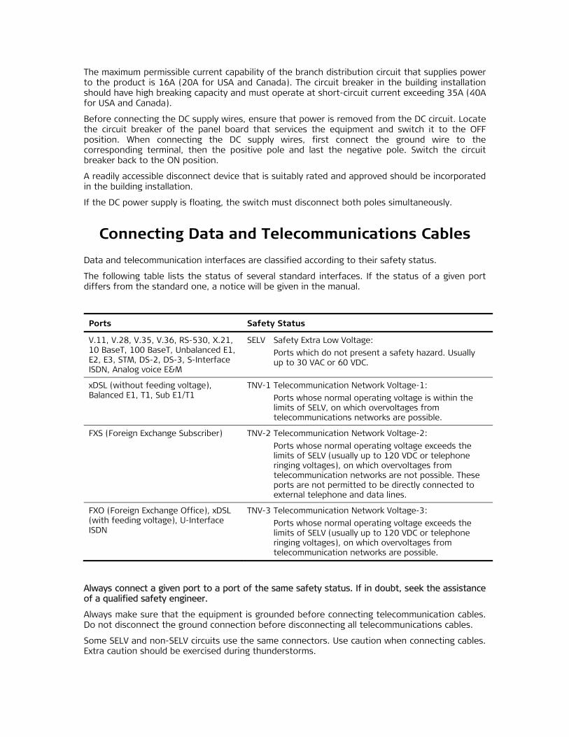
Data and telecommunication interfaces are classified according to their safety status.
The following table lists the status of several standard interfaces. If the status of a given port differs from the standard one, a notice will be given in the manual.
Ports Safety Status
V.11, V.28, V.35, V.36, RS-530, X.21, 10 BaseT, 100 BaseT, Unbalanced E1, E2, E3, STM, DS-2, DS-3, S-Interface ISDN, Analog voice E&M
SELV Safety Extra Low Voltage:
Ports which do not present a safety hazard. Usually up to 30 VAC or 60 VDC.
xDSL (without feeding voltage), Balanced E1, T1, Sub E1/T1
TNV-1 Telecommunication Network Voltage-1:
Ports whose normal operating voltage is within the limits of SELV, on which overvoltages from telecommunications networks are possible.
FXS (Foreign Exchange Subscriber) TNV-2 Telecommunication Network Voltage-2:
Ports whose normal operating voltage exceeds the limits of SELV (usually up to 120 VDC or telephone ringing voltages), on which overvoltages from telecommunication networks are not possible. These ports are not permitted to be directly connected to external telephone and data lines.
FXO (Foreign Exchange Office), xDSL (with feeding voltage), U-Interface ISDN
TNV-3 Telecommunication Network Voltage-3:
Ports whose normal operating voltage exceeds the limits of SELV (usually up to 120 VDC or telephone ringing voltages), on which overvoltages from telecommunication networks are possible.
Always connect a given port to a port of the same safety status. If in doubt, seek the assistance of a qualified safety engineer.
Always make sure that the equipment is grounded before connecting telecommunication cables. Do not disconnect the ground connection before disconnecting all telecommunications cables.
Some SELV and non-SELV circuits use the same connectors. Use caution when connecting cables. Extra caution should be exercised during thunderstorms.

When using shielded or coaxial cables, verify that there is a good ground connection at both ends. The grounding and bonding of the ground connections should comply with the local codes.
The telecommunication wiring in the building may be damaged or present a fire hazard in case of contact between exposed external wires and the AC power lines. In order to reduce the risk, there are restrictions on the diameter of wires in the telecom cables, between the equipment and the mating connectors.
To reduce the risk of fire, use only No. 26 AWG or larger telecommunication line cords.
Pour réduire les risques s’incendie, utiliser seulement des conducteurs de télécommunications 26 AWG ou de section supérieure.
Some ports are suitable for connection to intra-building or non-exposed wiring or cabling only. In such cases, a notice will be given in the installation instructions.
Do not attempt to tamper with any carrier-provided equipment or connection hardware.
Electromagnetic Compatibility (EMC)
The equipment is designed and approved to comply with the electromagnetic regulations of major regulatory bodies. The following instructions may enhance the performance of the equipment and will provide better protection against excessive emission and better immunity against disturbances.
A good ground connection is essential. When installing the equipment in a rack, make sure to remove all traces of paint from the mounting points. Use suitable lock-washers and torque. If an external grounding lug is provided, connect it to the ground bus using braided wire as short as possible.
The equipment is designed to comply with EMC requirements when connecting it with unshielded twisted pair (UTP) cables. However, the use of shielded wires is always recommended, especially for high-rate data. In some cases, when unshielded wires are used, ferrite cores should be installed on certain cables. In such cases, special instructions are provided in the manual.
Disconnect all wires which are not in permanent use, such as cables used for one-time configuration.
The compliance of the equipment with the regulations for conducted emission on the data lines is dependent on the cable quality. The emission is tested for UTP with 80 dB longitudinal conversion loss (LCL).
Unless otherwise specified or described in the manual, TNV-1 and TNV-3 ports provide secondary protection against surges on the data lines. Primary protectors should be provided in the building installation.
The equipment is designed to provide adequate protection against electro-static discharge (ESD). However, it is good working practice to use caution when connecting cables terminated with plastic connectors (without a grounded metal hood, such as flat cables) to sensitive data lines. Before connecting such cables, discharge yourself by touching ground or wear an ESD preventive wrist strap.
Caution
Attention

FCC-15 User Information
This equipment has been tested and found to comply with the limits of the Class A digital device, pursuant to Part 15 of the FCC rules. These limits are designed to provide reasonable protection against harmful interference when the equipment is operated in a commercial environment. This equipment generates, uses and can radiate radio frequency energy and, if not installed and used in accordance with the Installation and Operation manual, may cause harmful interference to the radio communications. Operation of this equipment in a residential area is likely to cause harmful interference in which case the user will be required to correct the interference at his own expense.
Canadian Emission Requirements
This Class A digital apparatus meets all the requirements of the Canadian Interference-Causing Equipment Regulation.
Cet appareil numérique de la classe A respecte toutes les exigences du Règlement sur le matériel brouilleur du Canada.
Warning per EN 55022 (CISPR-22)
This is a class A product. In a domestic environment, this product may cause radio interference, in which case the user will be required to take adequate measures.
Cet appareil est un appareil de Classe A. Dans un environnement résidentiel, cet appareil peut provoquer des brouillages radioélectriques. Dans ces cas, il peut être demandé à l’utilisateur de prendre les mesures appropriées.
Das vorliegende Gerät fällt unter die Funkstörgrenzwertklasse A. In Wohngebieten können beim Betrieb dieses Gerätes Rundfunkströrungen auftreten, für deren Behebung der Benutzer verantwortlich ist.
Warning
Avertissement
Achtung
Fra
nça
is
Mise au rebut du produit
Afin de faciliter la réutilisation, le recyclage ainsi que d'autres formes de récupération d'équipement mis au rebut dans le cadre de la protection de l'environnement, il est demandé au propriétaire de ce produit RAD de ne pas mettre ce dernier au rebut en tant que déchet municipal non trié, une fois que le produit est arrivé en fin de cycle de vie. Le client devrait proposer des solutions de réutilisation, de recyclage ou toute autre forme de mise au rebut de cette unité dans un esprit de protection de l'environnement, lorsqu'il aura fini de l'utiliser.
Instructions générales de sécurité
Les instructions suivantes servent de guide général d'installation et d'opération sécurisées des produits de télécommunications. Des instructions supplémentaires sont éventuellement indiquées dans le manuel.
Symboles de sécurité
Ce symbole peut apparaitre sur l'équipement ou dans le texte. Il indique des risques potentiels de sécurité pour l'opérateur ou le personnel de service, quant à l'opération du produit ou à sa maintenance.
Danger de choc électrique ! Evitez tout contact avec la surface marquée tant que le produit est sous tension ou connecté à des lignes externes de télécommunications.
Mise à la terre de protection : la cosse ou la borne marquée devrait être connectée à la prise de terre de protection du bâtiment.
Avertissement

Fra
nça
is
Certains produits peuvent être équipés d'une diode laser. Dans de tels cas, une étiquette indiquant la classe laser ainsi que d'autres avertissements, le cas échéant, sera jointe près du transmetteur optique. Le symbole d'avertissement laser peut aussi être joint.
Veuillez observer les précautions suivantes :
• Avant la mise en marche de l'équipement, assurez-vous que le câble de fibre optique est intact et qu'il est connecté au transmetteur.
• Ne tentez pas d'ajuster le courant de la commande laser.
• N'utilisez pas des câbles ou connecteurs de fibre optique cassés ou sans terminaison et n'observez pas directement un rayon laser.
• L'usage de périphériques optiques avec l'équipement augmentera le risque pour les yeux.
• L'usage de contrôles, ajustages ou procédures autres que celles spécifiées ici pourrait résulter en une dangereuse exposition aux radiations.
ATTENTION : Le rayon laser peut être invisible !
Les utilisateurs pourront, dans certains cas, insérer leurs propres émetteurs-récepteurs Laser SFP dans le produit. Les utilisateurs sont avertis que RAD ne pourra pas être tenue responsable de tout dommage pouvant résulter de l'utilisation d'émetteurs-récepteurs non conformes. Plus particulièrement, les utilisateurs sont avertis de n'utiliser que des produits approuvés par l'agence et conformes à la réglementation locale de sécurité laser pour les produits laser de classe 1.
Respectez toujours les précautions standards de sécurité durant l'installation, l'opération et la maintenance de ce produit. Seul le personnel de service qualifié et autorisé devrait effectuer l'ajustage, la maintenance ou les réparations de ce produit. Aucune opération d'installation, d'ajustage, de maintenance ou de réparation ne devrait être effectuée par l'opérateur ou l'utilisateur.
Manipuler des produits sous tension
Règles générales de sécurité
Ne pas toucher ou altérer l'alimentation en courant lorsque le câble d'alimentation est branché. Des tensions de lignes peuvent être présentes dans certains produits, même lorsque le commutateur (s'il est installé) est en position OFF ou si le fusible est rompu. Pour les produits alimentés par CC, les niveaux de tension ne sont généralement pas dangereux mais des risques de courant peuvent toujours exister.
Avant de travailler sur un équipement connecté aux lignes de tension ou de télécommunications, retirez vos bijoux ou tout autre objet métallique pouvant venir en contact avec les pièces sous tension.
Sauf s'il en est autrement indiqué, tous les produits sont destinés à être mis à la terre durant l'usage normal. La mise à la terre est fournie par la connexion de la fiche principale à une prise murale équipée d'une borne protectrice de mise à la terre. Si une cosse de mise à la terre est fournie avec le produit, elle devrait être connectée à tout moment à une mise à la terre de protection par un conducteur de diamètre 18 AWG ou plus. L'équipement monté en châssis ne devrait être monté que sur des châssis et dans des armoires mises à la terre.
Branchez toujours la mise à la terre en premier et débranchez-la en dernier. Ne branchez pas des câbles de télécommunications à un équipement qui n'est pas mis à la terre. Assurez-vous que tous les autres câbles sont débranchés avant de déconnecter la mise à la terre.
Avertissement

Fra
nça
is
Connexion au courant du secteur
Assurez-vous que l'installation électrique est conforme à la réglementation locale.
Branchez toujours la fiche de secteur à une prise murale équipée d'une borne protectrice de mise à la terre.
La capacité maximale permissible en courant du circuit de distribution de la connexion alimentant le produit est de 16A (20A aux Etats-Unis et Canada). Le coupe-circuit dans l'installation du bâtiment devrait avoir une capacité élevée de rupture et devrait fonctionner sur courant de court-circuit dépassant 35A (40A aux Etats-Unis et Canada).
Branchez toujours le câble d'alimentation en premier à l'équipement puis à la prise murale. Si un commutateur est fourni avec l'équipement, fixez-le en position OFF. Si le câble d'alimentation ne peut pas être facilement débranché en cas d'urgence, assurez-vous qu'un coupe-circuit ou un disjoncteur d'urgence facilement accessible est installé dans l'installation du bâtiment.
Le disjoncteur devrait déconnecter simultanément les deux pôles si le système de distribution de courant est de type IT.
Connexion d'alimentation CC
Sauf s'il en est autrement spécifié dans le manuel, l'entrée CC de l'équipement est flottante par rapport à la mise à la terre. Tout pôle doit être mis à la terre en externe.
A cause de la capacité de courant des systèmes à alimentation CC, des précautions devraient être prises lors de la connexion de l'alimentation CC pour éviter des courts-circuits et des risques d'incendie.
Assurez-vous que l'alimentation CC est isolée de toute source de courant CA (secteur) et que l'installation est conforme à la réglementation locale.
La capacité maximale permissible en courant du circuit de distribution de la connexion alimentant le produit est de 16A (20A aux Etats-Unis et Canada). Le coupe-circuit dans l'installation du bâtiment devrait avoir une capacité élevée de rupture et devrait fonctionner sur courant de court-circuit dépassant 35A (40A aux Etats-Unis et Canada).
Avant la connexion des câbles d'alimentation en courant CC, assurez-vous que le circuit CC n'est pas sous tension. Localisez le coupe-circuit dans le tableau desservant l'équipement et fixez-le en position OFF. Lors de la connexion de câbles d'alimentation CC, connectez d'abord le conducteur de mise à la terre à la borne correspondante, puis le pôle positif et en dernier, le pôle négatif. Remettez le coupe-circuit en position ON.
Un disjoncteur facilement accessible, adapté et approuvé devrait être intégré à l'installation du bâtiment.
Le disjoncteur devrait déconnecter simultanément les deux pôles si l'alimentation en courant CC est flottante.
LRS-102 Ver. 2.0 1
Quick Start Guide
If you are familiar with the LRS-102, use this guide to prepare it for operation, starting from its factory-default configuration.
Before performing the procedures described below, review the safety precautions given in Chapter 2.
Installing LRS-102
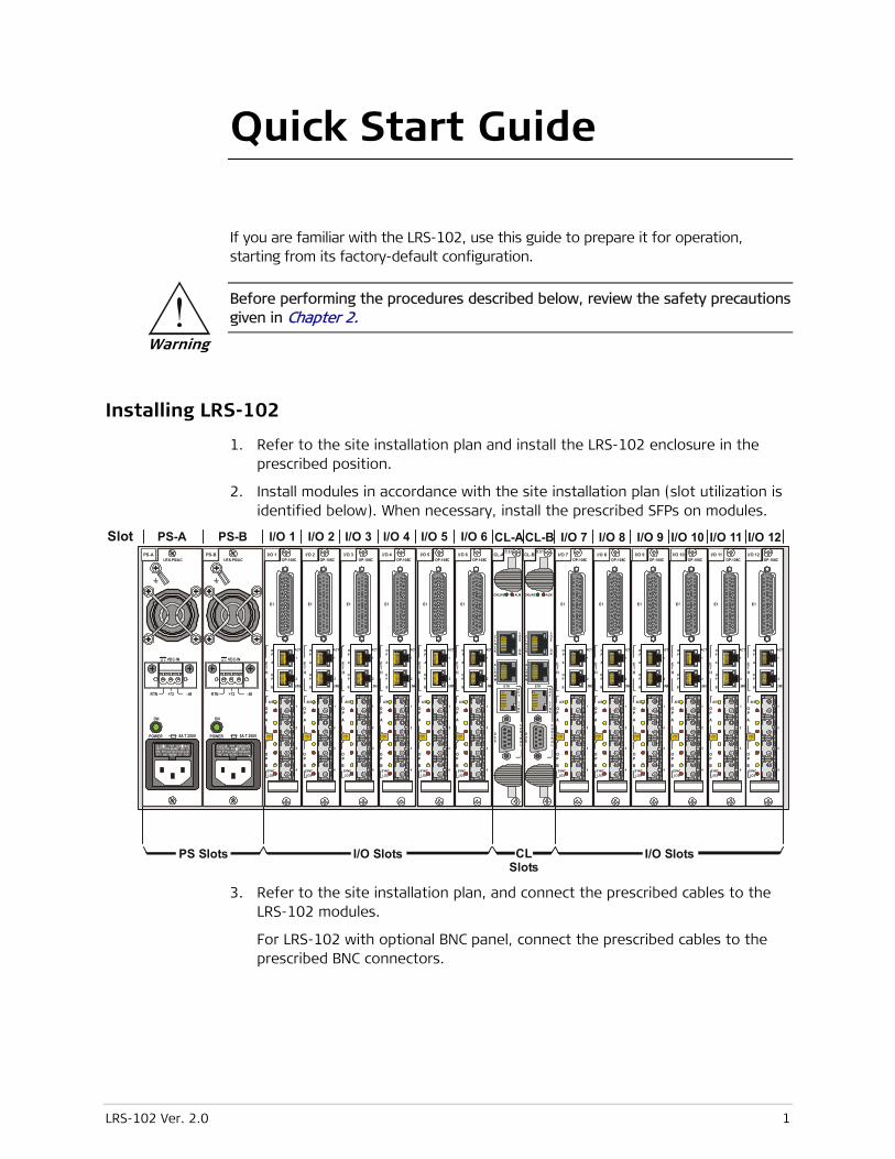
1. Refer to the site installation plan and install the LRS-102 enclosure in the prescribed position.
2. Install modules in accordance with the site installation plan (slot utilization is identified below). When necessary, install the prescribed SFPs on modules.
E1
LASERCLASS
1
OP
A
OPA
OPB
ACT
1
2OP
B
ETH
AIS
SYNCLOS
2
1
3
4
TXR
XTX
RXTX
RXTX
RX
E1
LASERCLASS
1
OP
A
OPA
OPB
ACT
1
2OP
B
ETH
AIS
SYNCLOS
2
1
3
4
TXR
XTX
RXTX
RXTX
RX
E1
LASERCLASS
1
OP
A
OPA
OPB
ACT
1
2OP
B
ETH
AIS
SYNCLOS
2
1
3
4
TXR
XTX
RXTX
RXTX
RX
E1
LASERCLASS
1
OP
A
OPA
OPB
ACT
1
2OP
B
ETH
AIS
SYNCLOS
2
1
3
4
TXR
XTX
RXTX
RXTX
RX
E1
LASERCLASS
1
OP
A
OPA
OPB
ACT
1
2OP
B
ETH
AIS
SYNCLOS
2
1
3
4
TXR
XTX
RXTX
RXTX
RX
OP-108C
E1
LASERCLASS
1
OP
A
OPA
OPB
ACT
1
2OP
B
ETH
AIS
SYNCLOS
2
1
3
4TX
RX
TXRX
TXRX
TXR
X
OP-108COP-108COP-108COP-108COP-108C
E1
LASERCLASS
1
OP
A
OPA
OPB
ACT
1
2OP
B
ETH
AIS
SYNCLOS
2
1
3
4
TXRX
TXRX
TXRX
TXR
X
E1
LASERCLASS
1
OP
A
OPA
OPB
ACT
1
2OP
B
ETH
AIS
SYNCLOS
2
1
3
4
TXRX
TXRX
TXRX
TXR
X
E1
LASERCLASS
1
OP
A
OPA
OPB
ACT
1
2OP
B
ETH
AIS
SYNCLOS
2
1
3
4
TXRX
TXRX
TXRX
TXR
X
E1
LASERCLASS
1
OP
A
OPA
OPB
ACT
1
2OP
B
ETH
AIS
SYNCLOS
2
1
3
4
TXRX
TXRX
TXRX
TXR
X
E1
LASERCLASS
1
OP
A
OPA
OPB
ACT
1
2OP
B
ETH
AIS
SYNCLOS
2
1
3
4
TXRX
TXRX
TXRX
TXR
X
OP-108C
E1
LASERCLASS
1
OP
A
OPA
OPB
ACT
1
2OP
B
ETH
AIS
SYNCLOS
2
1
3
4
TXRX
TXRX
TXRX
TXR
X
OP-108COP-108COP-108COP-108COP-108C
PS Slots
PS-ASlot PS-B I/O 1 I/O 2 I/O 3 I/O 4 I/O 5 I/O 6 I/O 7 I/O 8 I/O 9 I/O 10 I/O 11 I/O 12CL-ACL-B
CL Slots
I/O Slots I/O Slots
PS-B I/O 1 I/O 2 I/O 3 I/O 4 I/O 5 I/O 6 I/O 9 I/O 10 I/O 11 I/O 12CL-A CL-BPS-A
5A T 250V
ON
POWER
LRS-PS/AC
RTN -48+72
VDC-IN
5A T 250V
ON
POWER
LRS-PS/AC
RTN -48+72
VDC-IN
ONLINE ALM
ALARM
DCE
LOS
ON
CLOCK
ACT
LINK
CONTROL
ONLINE ALM
ALARM
DCE
LOS
ON
CLOCK
ACT
LINK
CONTROL
ETH ETH
3. Refer to the site installation plan, and connect the prescribed cables to the LRS-102 modules.
For LRS-102 with optional BNC panel, connect the prescribed cables to the prescribed BNC connectors.
Warning

Quick Start Guide Installation and Operation Manual
2 LRS-102 Ver. 2.0
Configuration Instructions
Turn On
1. Connect the power cable(s) first to the connector on the PS module, and then to the power outlet. For DC cables, pay attention to polarity.
2. Monitor the power-up initialization process.
3. After the power-up initialization ends, all the POWER indicators must light, the ON LINE indicator of the active CL module lights in green and that of the other CL module flashes slowly in green.
Preparations for Configuration
1. Connect a terminal to the CONTROL DCE connector of the active CL module (use a straight cable).
You can also connect the terminal in parallel to the CONTROL DCE connectors of both CL modules installed in the LRS-102, using a Y-cable.
You may use any standard ASCII terminal (dumb terminal or personal computer emulating an ASCII terminal) equipped with an RS-232 communication interface. Make sure to use VT-100 terminal emulation.
2. Configure the terminal for communication with the LRS-102.
If the LRS-102 default configuration has not yet been changed, configure the terminal for 115.2 kbps, one start bit, eight data bits, no parity, and one stop bit. Select the full-duplex mode, echo off, and disable any type of flow control.
3. Press <Enter> once to obtain the log-in screen.
If the power-up initialization has not yet been completed, you may see the decompression and initialization process. In this case, wait for the prompt: In order to start working - press the ENTER button for few times before pressing <Enter>.
4. Log in as administrator.
If the LRS-102 default user name and password have not yet been changed, log in as administrator using su as the user name and 1234 for password.
5. If your password is accepted, you will see the LRS-102 main menu.
Note

Installation and Operation Manual Quick Start Guide
LRS-102 Ver. 2.0 3
Configuration Sequence
The table below provides the LRS-102 configuration sequence.
Step Action Using …
1 Select the default database Configuration > DB Tools > Default DB
2 If the LRS-102 is equipped with all the
necessary modules, load the hardware
configuration.
Alternatively, configure the modules and
then reload the factory-default parameters
installed in the LRS-102. You can also
program modules not yet installed in the
chassis
Configuration > DB Tools > Load HW
Configuration > System > Card Type
3 Configure the preliminary set of IP
communication parameters
Configuration > Quick Setup
4 Configure CONTROL DCE port parameters Configuration > System > Control Port > Serial Port
5 Configure CONTROL ETH port parameters Configuration > System > Control Port > ETH
6 Configure LRS-102 management access Configuration > System > Management > Mng Access
7 Configure specific managers Configuration > System > Management > Manager List
8 Configure the LRS-102 logistic parameters Configuration > System > Management > Device Info
9 Set LRS-102 real-time clock Configuration > System > Date & Time
10 Optional: configure the station clock
interfaces of the CLS.1 modules
Configuration > Physical Layer > I/O > CL >
CL-A, CL-B > Station Clock
11 Configure the physical layer parameters of
the I/O modules in accordance with their
Installation and Operation Manuals
Configuration > Physical Layer > I/O > I/O-1 to I/O-12
12 Prepare the LRS-102 for SNMP
management:
1. Select the SNMP support mode
(enable/disable SNMPv3).
If SNMP support mode is changed, save
to activate the change before
continuing.
2. When SNMPv3 is Disabled, configure
SNMPv1 community names.
3. When SNMPv3 is Enabled, configure
parameters in the following order:
– SNMP Engine ID
– SNMPv3 users
– SNMPv3 targets and notifications
– Configure SNMPv1/SNMPv3 mapping
Configuration > System > Management > SNMPv3
Configuration > System > Management > Host IP
Configuration > System > Management > SNMP Engine ID
Configuration > System > Management > SNMPv3 Setting
> Users
Configuration > System > Management > SNMPv3 Setting
> Targets & Notify
Configuration > System > Management > SNMPv3 Setting
> SNMPv1/v3 Mapping

Quick Start Guide Installation and Operation Manual
4 LRS-102 Ver. 2.0
Step Action Using …
13 Configure Ethernet traffic flows Configuration > Applications > Ethernet Services > Flows
14 Configure the Ethernet management flow Configuration > System > Management > Flow
15 Configure LRS-102 alarm handling Configuration > System > Alarms Configuration
16 Save the final configuration as a database Configuration > DB Tools > Update DB
17 If necessary, prepare additional databases To start from an existing database, use Configuration >
DB Tools > Load DB. Repeat the relevant steps as needed
to create a new database
For your convenience, a navigation map of the LRS-102 supervision terminal menus is also provided below.

Installation and Operation Manual Quick Start Guide
LRS-102 Ver. 2.0 5
Main Menu
Inventory Diagnostics Monitoring File Utilities
S/W & File Transfer CL
System
Card Type
Alarms Configuration
Applications
Ethernet Services
Management
System
Quick Setup DB Tools
Reset Device
Date & Time
Control Port
Physical Layer
I/O Load DBDefault DBLoad HWUpdate DBDelete DB
Active Alarms (ON)Active Alarms (ALL)Clear AlarmsEvent LogCL StatusRemote Agents
System
System InfoSW/HW Rev
Configuration
I/O 1I/O 2
I/O 12
. .. .. .. .
Ping Test
Active Tests
Physical Layer
Physical Layer
S/W & File Transfer I/O
TFTPDownload to CardsDownload StatusDirDelete File
Device InfoHost IPManager ListMng AccessFlowSNMP Engine IDSNMPv3SNMPv3 Setting - SNMPv3 Enabled only
Serial PortETH
Display Date & TimeSet Date FormatSet DateSet Time
Alarm AttributesAlarm ReportAlarm PriorityInit Alarm PriorityInit Alarm ReportAlarm Window
CL
CL-ACL-B
I/O
I/O 1I/O 2
I/O 12
. .. .. .. .
CL
CL-ACL-B
Host IP AddressSubnet MaskDefault Gateway
Flows
CLS.1 only
CLS.1 only
Supervision Terminal Navigation Map

Quick Start Guide Installation and Operation Manual
6 LRS-102 Ver. 2.0
LRS-102 Ver. 2.0 i
Contents
Chapter 1. Introduction
1.1 Overview.................................................................................................................... 1-1 Product Options ...................................................................................................... 1-1 Applications ............................................................................................................ 1-2 Features ................................................................................................................. 1-3
1.2 Physical Description ................................................................................................... 1-5 System Structure .................................................................................................... 1-5 Equipment Description ............................................................................................ 1-5 CL Modules ............................................................................................................. 1-7 Power Supply (PS) Modules ..................................................................................... 1-7 I/O Modules ............................................................................................................ 1-8
1.3 Functional Description .............................................................................................. 1-10 Management Subsystem Functions ....................................................................... 1-10
Management Support ....................................................................................... 1-11 Remote Software and Configuration Updating .................................................. 1-12 Supervisory Port Capabilities ............................................................................. 1-12 Out-of-Band Access via CL Ethernet Management Port ..................................... 1-12 CL Module Redundancy .................................................................................... 1-13 Performance Monitoring Statistics .................................................................... 1-13 Alarm Collection and Reporting ......................................................................... 1-13 Diagnostic Functions ........................................................................................ 1-14
Timing Subsystem ................................................................................................. 1-14 Internal Timing ................................................................................................. 1-14 Station Timing (CLS.1 Modules only) ................................................................. 1-14 Station Clock Interface Characteristics (CLS.1 Modules only) ............................. 1-15
Power Supply Subsystem ...................................................................................... 1-15 PS Modules ...................................................................................................... 1-15 Feed Voltage Sources ....................................................................................... 1-16
1.4 Technical Specifications ............................................................................................ 1-17 CL Module ............................................................................................................. 1-18
Chapter 2. Installation and Setup
2.1 Site Requirements and Prerequisites .......................................................................... 2-1 AC Power Requirements .......................................................................................... 2-1 DC Power Requirements .......................................................................................... 2-1 Payload Connection Requirements .......................................................................... 2-2
Connections to E1 and T1 Ports ......................................................................... 2-2 Connections to Optical Ports .............................................................................. 2-3 Optical Cable Requirements ................................................................................ 2-3
Connections to Station Clock (Optional – CLS.1 Modules Only) ................................ 2-3 Management Connection Requirements .................................................................. 2-4
Ethernet Connections to CL Modules .................................................................. 2-4 Connection to Serial Port .................................................................................... 2-4
Connections to Alarm Port ...................................................................................... 2-4 Front and Rear Panel Clearance ............................................................................... 2-5 Ambient Requirements ........................................................................................... 2-5 Electromagnetic Compatibility Considerations .......................................................... 2-5
2.2 Package Contents ...................................................................................................... 2-5 2.3 Required Equipment ................................................................................................... 2-5
Table of Contents Installation and Operation Manual
ii LRS-102 Ver. 2.0
2.4 Mounting the LRS-102 Unit ........................................................................................ 2-6 Safety Precautions .................................................................................................. 2-6 Grounding .............................................................................................................. 2-6 Protection against ESD ............................................................................................ 2-7 Proper Handling of Modules .................................................................................... 2-7 Familiarization with LRS-102 ................................................................................... 2-8
Rear View ........................................................................................................... 2-9 Standard Front Panel ........................................................................................ 2-10 BNC Patch Panel Option ................................................................................... 2-11
Installing PS Modules ............................................................................................ 2-11 Module Panels .................................................................................................. 2-11 Internal Jumpers ............................................................................................... 2-13 Installing a PS Module....................................................................................... 2-14 Removing a PS Module ..................................................................................... 2-14
Installing CL Modules ............................................................................................. 2-14 Module Panels .................................................................................................. 2-14 Installing a CL Module ....................................................................................... 2-17 Removing a CL Module ..................................................................................... 2-17 Replacing a CL Module During Equipment Operation - LRS-102 Chassis with two CL Modules ........................................................................................................... 2-17 Replacing a CL Module During Equipment Operation - LRS-102 Chassis with Single CL Module ........................................................................................................ 2-18
Installing I/O Modules ............................................................................................ 2-18 Installing Blank Panels ........................................................................................... 2-18 Installing the LRS-102 Enclosure ........................................................................... 2-19
Installing in 19” Rack ........................................................................................ 2-19 Installing in 23” Rack ........................................................................................ 2-20
2.5 Connecting to LRS-102 ............................................................................................ 2-20 Grounding the LRS-102 ......................................................................................... 2-20 Connecting to Power ............................................................................................ 2-21 Connecting to External Feed Voltages .................................................................... 2-21 Connecting to CL Module Management and Supervision Ports ................................ 2-21 Connecting to the CLOCK Connector (CLS.1 Modules only) ..................................... 2-22 Connecting Cables to Optical Ports ........................................................................ 2-23
Laser Safety ..................................................................................................... 2-23 Connection Instructions .................................................................................... 2-23
Connecting Coaxial Cables to LRS-102 Patch Panel ................................................ 2-24 Connecting to LRS-102 I/O Modules ...................................................................... 2-24
Chapter 3. Operation
3.1 Turning LRS-102 On ................................................................................................... 3-1 3.2 Indications ................................................................................................................. 3-3
System Indications .................................................................................................. 3-3 CONTROL ETH Interface Status Indications .............................................................. 3-3 CLS.1 CLOCK Interface Status Indications ................................................................ 3-3
3.3 Default Settings ......................................................................................................... 3-4 3.4 Configuration and Management Alternatives .............................................................. 3-9
Access Levels for Configuration and Management ................................................... 3-9 Working with Supervision Terminal ........................................................................ 3-10
Preliminary Configuration Sequence .................................................................. 3-12 Configuring LRS-102 via Supervisory Terminal ................................................... 3-15 Preparing New Configuration Parameters .......................................................... 3-16 Validity Checks ................................................................................................. 3-17

Installation and Operation Manual Table of Contents
LRS-102 Ver. 2.0 iii
LRS-102 Power-up Process ............................................................................... 3-17 Organization of Terminal Screens ..................................................................... 3-17 General Supervision Terminal Operating Procedures .......................................... 3-19 Saving Changes to the Configuration Database ................................................. 3-21 Ending a Terminal Configuration Session ........................................................... 3-21 Menu Structure of Supervision Utility ................................................................ 3-21
Working with Telnet .............................................................................................. 3-31 General Telnet Operating Procedures ................................................................ 3-31
Working with Web Browsers .................................................................................. 3-32 Guidelines for Using Web Browsers ................................................................... 3-32 Preparations for Using Web Browsers ............................................................... 3-32 General Web Browser Operating Procedures ..................................................... 3-32 Navigating the ConfiguRAD Menus .................................................................... 3-33
Working with SNMP Management Stations ............................................................ 3-33 Support for SNMP Management ........................................................................ 3-33 Preparing for SNMP Management ..................................................................... 3-34
3.5 Turning the LRS-102 Off .......................................................................................... 3-35
Chapter 4. Configuration
4.1 Managing LRS-102 Configuration Databases ............................................................... 4-2 Overview of DB Tools Menu .................................................................................... 4-3 Database Management ........................................................................................... 4-3
4.2 Configuring System Parameters .................................................................................. 4-9 Overview of System Configuration Submenu ........................................................... 4-9 Reloading Factory Defaults ................................................................................... 4-12 Reset Device ......................................................................................................... 4-13 Programming Modules .......................................................................................... 4-14 Quick Setup .......................................................................................................... 4-15 Configuring the Control Ports ................................................................................ 4-16
Configuring the Serial Ports .............................................................................. 4-17 Changing the User Authorizations and Security Parameters of the Serial Ports .. 4-18 Configuring the Ethernet (ETH) Port ................................................................. 4-23
Configuring Host IP Parameters and SNMP Communities (with SNMPv3 Disabled) ... 4-25 Configuring Management Access ........................................................................... 4-27 Configuring the Manager List (with SNMPv3 Disabled) ........................................... 4-28 Configuring System Logistic Information ................................................................ 4-31 Setting the Internal Date & Time ........................................................................... 4-31
4.3 Configuring LRS-102 for SNMPv3 Management ......................................................... 4-33 Overview of SNMPv3 Capabilities ........................................................................... 4-33
User-Based Security Model (USM) ..................................................................... 4-34 SNMP Security Levels ........................................................................................ 4-34 SNMPv3 Administrative Features ...................................................................... 4-35 View-Based Access Control Model (VACM) ......................................................... 4-35
Configuring SNMP Engine ID .................................................................................. 4-35 Enabling/Disabling SNMPv3 Security Features ........................................................ 4-37 Configuring for SNMP Management with SNMPv3 Security Features ....................... 4-38
SNMPv3 Configuration Sequence ...................................................................... 4-38 Configuring Authorized User Security Parameters ............................................. 4-40 Configuring SNMPv3 Management Attributes .................................................... 4-43 Configuring Target Parameters ......................................................................... 4-44 Configuring Notification Tags ........................................................................... 4-45 Configuring Target Transport Parameters .......................................................... 4-48 Configuring SNMPv1/v3 Mapping ...................................................................... 4-49
Table of Contents Installation and Operation Manual
iv LRS-102 Ver. 2.0
Viewing the Summary User Table ...................................................................... 4-50 Viewing the Summary Target Table ................................................................... 4-50
4.4 Configuring Physical Layer Parameters ...................................................................... 4-52 Overview of Physical Layer Configuration Submenu ............................................... 4-52 Selecting the Physical Ports to be Configured ........................................................ 4-53 Configuring the I/O Module Physical Ports ............................................................. 4-53 Configuring the CLS.1 Station Clock Port ............................................................... 4-54
4.5 Configuring Ethernet Applications ............................................................................. 4-58 Overview of Applications Submenu ........................................................................ 4-59 Configuring Ethernet Flows ................................................................................... 4-59
Traffic Flow Configuration Guidelines ................................................................ 4-59 Traffic Flow Configuration Procedure ................................................................ 4-60 Management Flow Configuration Procedure ...................................................... 4-65
4.6 Using the File Utilities............................................................................................... 4-70 Before Starting File Transfers ................................................................................ 4-70 File Transfers to CL Modules ................................................................................. 4-71
Updating the CL Management Software ............................................................ 4-72 Downloading a Configuration File ..................................................................... 4-74 Uploading a Configuration File .......................................................................... 4-74
File Transfers to I/O Modules ................................................................................ 4-74 Using the Dir Function ...................................................................................... 4-78 Deleting Files ................................................................................................... 4-79
4.7 Viewing Logistic (Inventory) Information ................................................................... 4-80 Displaying the System Inventory Screen ................................................................ 4-80
Chapter 5. Configuring Typical Applications
5.1 Overview.................................................................................................................... 5-1 5.2 Outline of Configuration Sequence ............................................................................. 5-1
Preliminary Configuration Sequence ........................................................................ 5-1 General Configuration Sequence ............................................................................. 5-2
Chapter 6. Troubleshooting and Diagnostics
6.1 Monitoring Performance ............................................................................................. 6-1 Overview of Monitoring Menu ................................................................................. 6-2 Monitoring the CL Module Status ............................................................................ 6-3 Displaying Information on Station Clock Ports (CLS.1 Modules only) ......................... 6-4 Displaying Information on LRS-102 Remote Agents ................................................. 6-5 Monitoring Physical Layer Performance ................................................................... 6-6
6.2 Detecting Configuration Errors ................................................................................... 6-8 6.3 Handling Alarms and Traps ....................................................................................... 6-11
Alarm Collection and Reporting ............................................................................. 6-11 Alarm Buffer .................................................................................................... 6-11 Alarm Relays .................................................................................................... 6-11
Customizing Alarm Handling (Alarm Configuration) ................................................ 6-11 Selecting the Alarm Attributes .......................................................................... 6-12 Selecting the Alarm Reporting Method .............................................................. 6-18 Changing the Alarm Priority .............................................................................. 6-20 Selecting the Alarm Threshold Window ............................................................. 6-22
Displaying Alarms .................................................................................................. 6-23 Displaying the Active Alarms in ON State .......................................................... 6-23 Displaying All the Active Alarms ........................................................................ 6-24
Interpreting Alarm Messages ................................................................................. 6-28

Installation and Operation Manual Table of Contents
LRS-102 Ver. 2.0 v
Traps Generated by LRS-102 ................................................................................. 6-35 6.4 Troubleshooting ....................................................................................................... 6-37
Preliminary Checks ................................................................................................ 6-37 Troubleshooting Procedure ................................................................................... 6-38
6.5 Frequently Asked Questions ..................................................................................... 6-39 6.6 Technical Support .................................................................................................... 6-41 6.7 Testing LRS-102 Operation ...................................................................................... 6-42
Overview of Diagnostics Menu .............................................................................. 6-42 Activating Tests and Loopbacks on I/O Modules .................................................... 6-43 Ping Test .............................................................................................................. 6-44 Displaying the Active Tests .................................................................................... 6-45
Appendix A. Connection Data
Appendix B. Installing New Software Releases

Table of Contents Installation and Operation Manual
vi LRS-102 Ver. 2.0
LRS-102 Ver. 2.0 Overview 1-1
Chapter 1
Introduction
1.1 Overview
LRS-102 is a high-density managed modem rack with 12 slots that can be equipped with independently operating I/O modules, which share the chassis management subsystem and power supply modules.
Extensive management capabilities, starting with supervision terminals and Telnet hosts and up to SNMP-based network management, confer complete control over all aspects of equipment operation, and support efficient provisioning and rapid response to changing requirements. To protect network operations against unauthorized access, LRS-102 supports SNMP management with authentication and privacy per SNMPv3, with continued support for SNMPv1.
Product Options
The following product options are available:
• Power supply: LRS-102 can be ordered with AC or DC power supply modules. Two types of PS modules are available:
Standard PS modules, which can provide up to at least 200W for AC-powered modules, and up to 250W for DC-powered modules to the modules installed in the LRS-102
Low power PS modules, which are sufficient for a LRS-102 fully equipped with OP-108C or OP-106C modules, or with no more than eight ASMi-54C modules.
• Common logic models: two types of common logic (CL) modules are available for LRS-102:
CL.1: includes the common logic and management functions of LRS-102. This model is suitable for all the current LRS-102 applications (the current applications do not require a station clock interface)
CLS.1: includes all the CL.1 functions, and in addition includes a station clock interface. This model is suitable for future applications in which the chassis will be equipped with modules which can use the station clock as a reference.
The generic term CL module is used when the information is applicable to all the CL models. Information applicable to only one CL model is explicitly identified.
Note
Chapter 1 Introduction Installation and Operation Manual
1-2 Overview LRS-102 Ver. 2.0
• Power supply redundancy: LRS-102 can be ordered with one power supply module, or with two power supply modules, for redundancy. Always use same type of PS module (either standard or low power), but you can mix AC and DC PS modules in the same chassis
• Common logic redundancy: LRS-102 can be ordered with one or two common logic (CL) modules of the same model.
Applications
The LRS-102 current version can be equipped with two types of I/O modules:
• Dual E1, respectively T1, and Ethernet multiplexer modules, OP-108C and/or OP-106C
• Ethernet over SHDSL 8-port SHDSL.bis I/O module, ASMi-54C
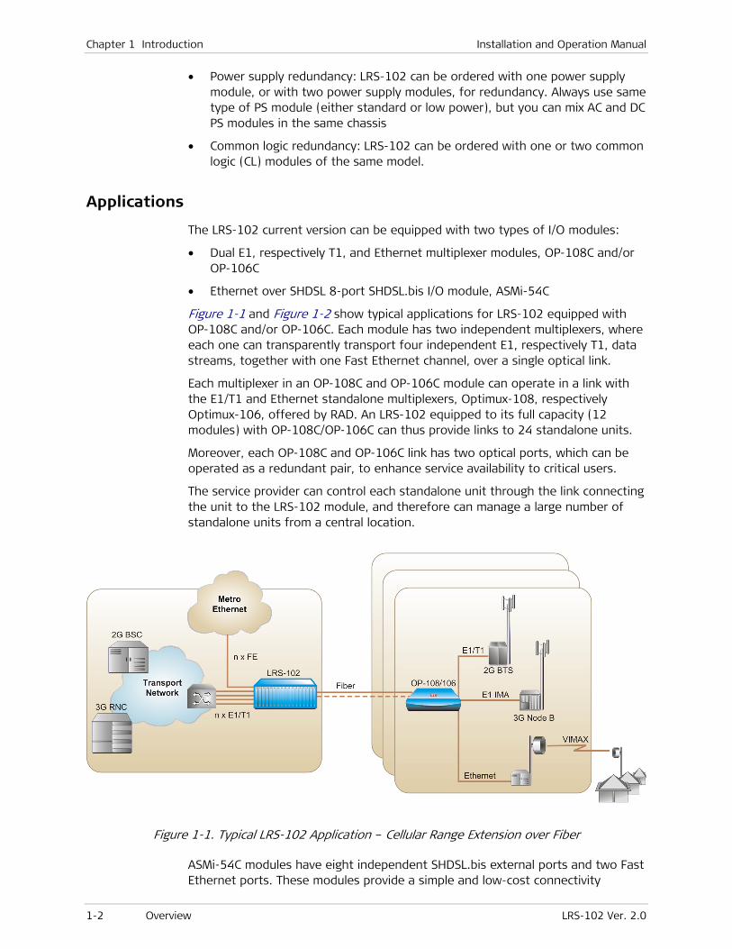
Figure 1-1 and Figure 1-2 show typical applications for LRS-102 equipped with OP-108C and/or OP-106C. Each module has two independent multiplexers, where each one can transparently transport four independent E1, respectively T1, data streams, together with one Fast Ethernet channel, over a single optical link.
Each multiplexer in an OP-108C and OP-106C module can operate in a link with the E1/T1 and Ethernet standalone multiplexers, Optimux-108, respectively Optimux-106, offered by RAD. An LRS-102 equipped to its full capacity (12 modules) with OP-108C/OP-106C can thus provide links to 24 standalone units.
Moreover, each OP-108C and OP-106C link has two optical ports, which can be operated as a redundant pair, to enhance service availability to critical users.
The service provider can control each standalone unit through the link connecting the unit to the LRS-102 module, and therefore can manage a large number of standalone units from a central location.
Figure 1-1. Typical LRS-102 Application – Cellular Range Extension over Fiber
ASMi-54C modules have eight independent SHDSL.bis external ports and two Fast Ethernet ports. These modules provide a simple and low-cost connectivity
Installation and Operation Manual Chapter 1 Introduction
LRS-102 Ver. 2.0 Overview 1-3
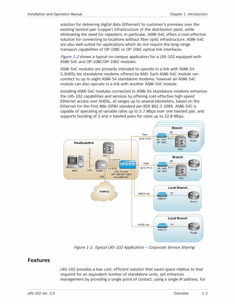
solution for delivering digital data (Ethernet) to customer’s premises over the existing twisted pair (copper) infrastructure of the distribution plant, while eliminating the need for repeaters. In particular, ASMi-54C offers a cost-effective solution for connecting to locations without fiber optic infrastructure. ASMi-54C are also well-suited for applications which do not require the long-range transport capabilities of OP-108C or OP-106C optical link interfaces.
Figure 1-2 shows a typical on-campus application for a LRS-102 equipped with ASMi-54C and OP-108C/OP-106C modules.
ASMi-54C modules are primarily intended to operate in a link with ASMi-54 G.SHDSL.bis standalone modems offered by RAD. Each ASMi-54C module can connect to up to eight ASMi-54 standalone modems, however an ASMi-54C module can also operate in a link with another ASMi-54C module.
Installing ASMi-54C modules connected to ASMi-54 standalone modems enhances the LRS-102 capabilities and services by offering cost-effective high-speed Ethernet access over SHDSL, at ranges up to several kilometers, based on the Ethernet for the First Mile (EFM) standard per IEEE 802.3-2005. ASMi-54C is capable of operating at variable rates up to 5.7 Mbps over one twisted pair, and supports bonding of 2 and 4 twisted pairs for rates up to 22.8 Mbps.
Figure 1-2. Typical LRS-102 Application – Corporate Service Sharing
Features
LRS-102 provides a low-cost, efficient solution that saves space relative to that required for an equivalent number of standalone units, yet enhances management by providing a single point of contact, using a single IP address, for
Chapter 1 Introduction Installation and Operation Manual
1-4 Overview LRS-102 Ver. 2.0
the management of all the modules installed in the chassis. Moreover, LRS-102 common management subsystem enables downloading software to any I/O module via the management link, as well as downloading updated LRS-102 management software. Up to two software versions can be stored for I/O modules. Each I/O module can be replaced, or its cables removed during operation, without interfering with the traffic carried by the other I/O modules in the chassis.
Redundancy with hot swapping is supported for all the critical LRS-102 subsystems (common logic and power supply), thereby achieving carrier-class availability. Redundancy is also supported for I/O modules that have this capability.
Extensive management capabilities confer complete control over all aspects of equipment operation, and support efficient provisioning and rapid response to changing requirements.
A wide range of inband and out-of-band management options are supported, starting with serial RS-232 interfaces for using a simple supervision terminal connected to the LRS-102, and including dedicated out-of-band Ethernet interfaces, and inband management via Ethernet interfaces located on I/O modules that enable Telnet and SNMP access from any location at which IP communication with the LRS-102 is possible, as well as management by means of Web browsers. Moreover, some types of I/O modules installed in the chassis can transfer management traffic to the far-end standalone units connected to their external links. Thus, LRS-102 provides organizations with the means needed to integrate the equipment installed in the LRS-102 chassis within the organizational management hierarchy, as well as manage seamlessly far-end equipment through the LRS-102.
LRS-102 can be powered from AC and/or DC sources. Only a single power supply module is required to provide power to a fully equipped LRS-102, however, for redundancy, LRS-102 can be equipped with two power supply modules. When the modules installed in the chassis must supply feed voltages to the connected equipment, the power supply modules enable connecting an external power source, for example, Ringer-2200N/ISDN standalone unit offered by RAD.
LRS-102 is a compact, 4U-high unit intended for installation in ANSI and ETSI racks. The units are cooled by free air convection. In addition, the power supply modules have miniature cooling fans installed on their front panels.
Installation and Operation Manual Chapter 1 Introduction
LRS-102 Ver. 2.0 Physical Description 1-5
1.2 Physical Description
System Structure
LRS-102 units use a modular chassis with slots in which modules are installed by the user to obtain the desired equipment configuration. LRS-102 configuration includes the following main subsystems:
• I/O subsystem, provides interfaces to the user’s equipment.
• Control subsystem, located on all the common logic (CL) modules.
• Power supply subsystem, located on the power supply (PS) modules
• Chassis. The main function of the chassis is to provide interconnections between the various common subsystems (power and management) of the chassis and the installed I/O modules.
The optional CLS.1 module has a station clock interface and timing distribution subsystem, for future applications.
CL and PS modules are always installed in their dedicated chassis slots, whereas the user interfacing modules can be installed in any of the other chassis slots (called I/O slots). Any operational LRS-102 system must include at least one CL module and one PS module. These modules are thus referred to as system modules. User interfacing modules, called I/O modules, are added to this basic configuration.
LRS-102 system modules are critical components, because a failure in any one of these modules could disable the whole system, whereas a failure in an I/O module affects only a small part of the system, and can be generally overcome by using alternate routes, putting unused capacity into service, etc. Therefore, in most applications LRS-102 units should be equipped with an additional redundant system module of each type.
The LRS-102 system is designed to automatically put a redundant module or subsystem in service in case the corresponding system component fails, thereby ensuring continuous system operation in the event of any single module failure. Moreover, redundant modules may be inserted or removed even while the system operates, without disrupting the traffic or degrading system performance.
Equipment Description
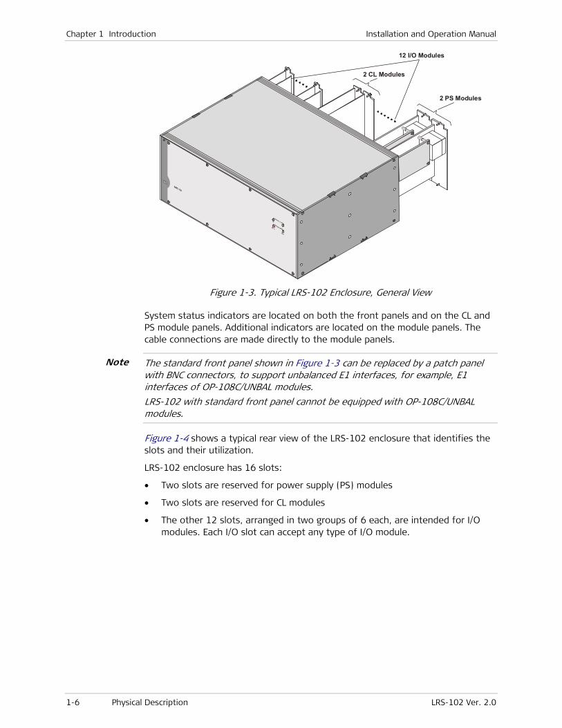
Figure 1-3 shows a general view of the LRS-102 enclosure. LRS-102 is built in a 4U-high enclosure that can be installed in 19” and 23” racks, using brackets attached to the sides of the enclosure, near the front or rear panel. Thus, a LRS-102 can be installed in accordance with the specific requirements of each site, either with the LRS-102 front panel toward the front of the rack (per ETSI practice), or with the module panels toward the front (per ANSI practice).
Note
Chapter 1 Introduction Installation and Operation Manual
1-6 Physical Description LRS-102 Ver. 2.0
2 CL Modules
12 I/O Modules
2 PS Modules
Figure 1-3. Typical LRS-102 Enclosure, General View
System status indicators are located on both the front panels and on the CL and PS module panels. Additional indicators are located on the module panels. The cable connections are made directly to the module panels.
The standard front panel shown in Figure 1-3 can be replaced by a patch panel with BNC connectors, to support unbalanced E1 interfaces, for example, E1 interfaces of OP-108C/UNBAL modules.
LRS-102 with standard front panel cannot be equipped with OP-108C/UNBAL modules.
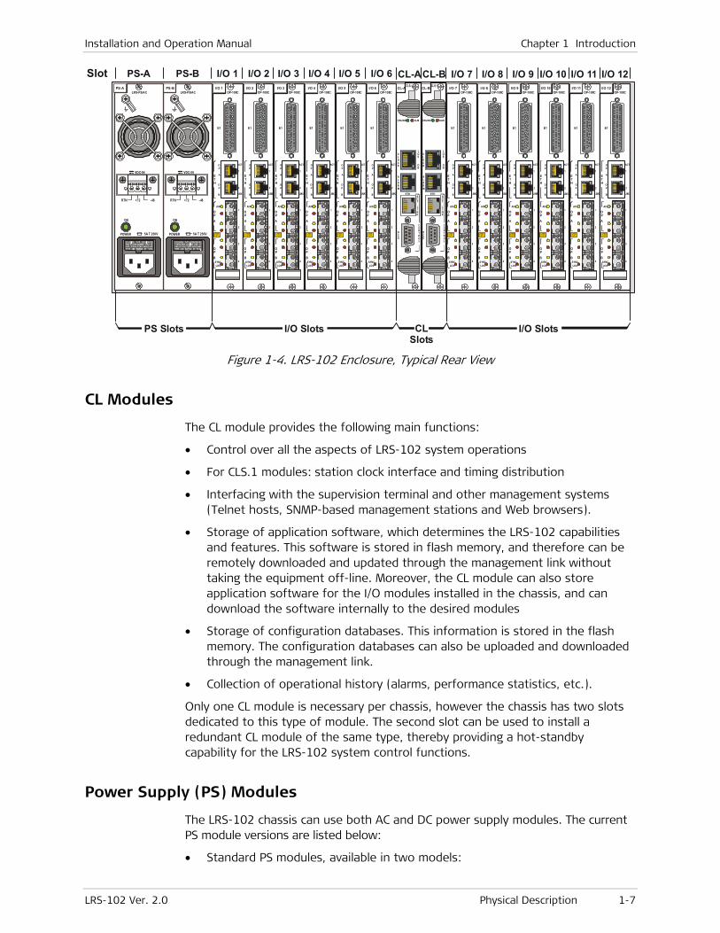
Figure 1-4 shows a typical rear view of the LRS-102 enclosure that identifies the slots and their utilization.
LRS-102 enclosure has 16 slots:
• Two slots are reserved for power supply (PS) modules
• Two slots are reserved for CL modules
• The other 12 slots, arranged in two groups of 6 each, are intended for I/O modules. Each I/O slot can accept any type of I/O module.
Note
Installation and Operation Manual Chapter 1 Introduction
LRS-102 Ver. 2.0 Physical Description 1-7
E1
LASERCLASS
1
OP
A
OPA
OPB
ACT
1
2OP
B
ETH
AIS
SYNCLOS
2
1
3
4
TXR
XTX
RXTX
RXTX
RX
E1
LASERCLASS
1
OP
A
OPA
OPB
ACT
1
2OP
B
ETH
AIS
SYNCLOS
2
1
3
4
TXR
XTX
RXTX
RXTX
RX
E1
LASERCLASS
1
OP
A
OPA
OPB
ACT
1
2OP
B
ETH
AIS
SYNCLOS
2
1
3
4
TXR
XTX
RXTX
RXTX
RX
E1
LASERCLASS
1
OP
A
OPA
OPB
ACT
1
2OP
B
ETH
AIS
SYNCLOS
2
1
3
4
TXR
XTX
RXTX
RXTX
RX
E1
LASERCLASS
1
OP
A
OPA
OPB
ACT
1
2OP
B
ETH
AIS
SYNCLOS
2
1
3
4
TXR
XTX
RXTX
RXTX
RX
OP-108C
E1
LASERCLASS
1
OP
A
OPA
OPB
ACT
1
2OP
B
ETH
AIS
SYNCLOS
2
1
3
4
TXR
XTX
RXTX
RXTX
RX
OP-108COP-108COP-108COP-108COP-108C
E1
LASERCLASS
1
OP
A
OPA
OPB
ACT
1
2OP
B
ETH
AIS
SYNCLOS
2
1
3
4
TXRX
TXRX
TXRX
TXRX
E1
LASERCLASS
1
OP
A
OPA
OPB
ACT
1
2OP
B
ETH
AIS
SYNCLOS
2
1
3
4TX
RXTX
RXTX
RXTX
RX
E1
LASERCLASS
1
OP
A
OPA
OPB
ACT
1
2OP
B
ETH
AIS
SYNCLOS
2
1
3
4
TXRX
TXRX
TXRX
TXRX
E1
LASERCLASS
1
OP
A
OPA
OPB
ACT
1
2OP
B
ETH
AIS
SYNCLOS
2
1
3
4
TXRX
TXRX
TXRX
TXRX
E1
LASERCLASS
1
OP
A
OPA
OPB
ACT
1
2OP
B
ETH
AIS
SYNCLOS
2
1
3
4
TXRX
TXRX
TXRX
TXRX
OP-108C
E1
LASERCLASS
1
OP
A
OPA
OPB
ACT
1
2OP
B
ETH
AIS
SYNCLOS
2
1
3
4
TXRX
TXRX
TXRX
TXRX
OP-108COP-108COP-108COP-108COP-108C
PS Slots
PS-ASlot PS-B I/O 1 I/O 2 I/O 3 I/O 4 I/O 5 I/O 6 I/O 7 I/O 8 I/O 9 I/O 10 I/O 11 I/O 12CL-ACL-B
CL Slots
I/O Slots I/O Slots
PS-B I/O 1 I/O 2 I/O 3 I/O 4 I/O 5 I/O 6 I/O 9 I/O 10 I/O 11 I/O 12CL-A CL-BPS-A
5A T 250V
ON
POWER
LRS-PS/AC
RTN -48+72
VDC-IN
5A T 250V
ON
POWER
LRS-PS/AC
RTN -48+72
VDC-IN
ONLINE ALM
ALARM
DCE
LOS
ON
CLOCK
ACT
LINK
CONTROL
ONLINE ALM
ALARM
DCE
LOS
ON
CLOCK
ACT
LINK
CONTROL
ETH ETH
Figure 1-4. LRS-102 Enclosure, Typical Rear View
CL Modules
The CL module provides the following main functions:
• Control over all the aspects of LRS-102 system operations
• For CLS.1 modules: station clock interface and timing distribution
• Interfacing with the supervision terminal and other management systems (Telnet hosts, SNMP-based management stations and Web browsers).
• Storage of application software, which determines the LRS-102 capabilities and features. This software is stored in flash memory, and therefore can be remotely downloaded and updated through the management link without taking the equipment off-line. Moreover, the CL module can also store application software for the I/O modules installed in the chassis, and can download the software internally to the desired modules
• Storage of configuration databases. This information is stored in the flash memory. The configuration databases can also be uploaded and downloaded through the management link.
• Collection of operational history (alarms, performance statistics, etc.).
Only one CL module is necessary per chassis, however the chassis has two slots dedicated to this type of module. The second slot can be used to install a redundant CL module of the same type, thereby providing a hot-standby capability for the LRS-102 system control functions.
Power Supply (PS) Modules
The LRS-102 chassis can use both AC and DC power supply modules. The current PS module versions are listed below:
• Standard PS modules, available in two models:

Chapter 1 Introduction Installation and Operation Manual
1-8 Physical Description LRS-102 Ver. 2.0
DC-powered module, PS/DC: 250W power supply module operating on -48 VDC (nominal), can provide a phantom feed voltage (-48 VDC) to I/O modules that require this voltage. When a higher voltage is required (for example, -120 VDC), it must be provided by an external source.
AC-powered module, PS/AC: 200W power supply module, operates on 110 VAC and 230 VAC, 50/60Hz (nominal voltage is marked on the module panel). When a phantom feed voltage must be supplied, it is always necessary to use an external voltage source.
• Low power PS modules, which are sufficient for a LRS-102 fully equipped with OP-108C or OP-106C modules, or with no more than eight ASMi-54C modules. Low power PS modules are available in two models:
DC-powered module, LRS-102-PS/DCLP: 112W power supply module operating on -48 VDC, can provide a phantom feed voltage (-48 VDC) to I/O modules that require this voltage. When a higher voltage is required (for example, -120 VDC), it must be provided by an external source.
AC-powered module, LRS-102-PS/ACLP: 112W power supply module, operates on 110 VAC and 230 VAC (nominal), 50/60 Hz. When a phantom feed voltage must be supplied, it is always necessary to use an external voltage source.
The recommended external feed voltage source is the Ringer-2200N/ISDN standalone unit offered by RAD.
The LRS-102 chassis has two PS slots, thereby enabling the installation of two PS modules. Normally, a single PS module per unit is sufficient.
However, a second PS module may be added, for redundancy: both modules must be of the same type (either standard, or low power), but it is allowed to install one AC-powered module and one DC-powered module. With a redundant PS module, both modules are connected to power and share the load when the system is operating. In case of failure or loss of input power, the remaining module continues to supply the power alone. Switch-over is thus automatic and does not disturb normal operation.
I/O Modules
Table 1-1 lists the I/O modules currently offered for the LRS-102. Contact RAD Marketing for information on additional modules that may be available for your specific application requirements.

Installation and Operation Manual Chapter 1 Introduction
LRS-102 Ver. 2.0 Physical Description 1-9
Table 1-1. LRS-102 I/O Modules
Module Description
OP-108C Dual E1 and Ethernet multiplexer, where each multiplexer operates
independently and can operate in a link with the Optimux-108 4 E1 and
Ethernet Multiplexer standalone unit offered by RAD.
Each multiplexer is capable of transparently transporting four
independent E1 data streams and one 100BASE-TX Ethernet channel
over one optical link. Each link has two optical ports, with
user-configurable redundancy between the two ports.
The optical ports can be equipped with field-replaceable SFPs. Support
for standard SFP optical transceivers for the STM-1/OC-3 link interfaces
enables selecting the optimal interface for each application.
High-performance SFPs available from RAD can achieve ranges up to
120 km/75 miles.
Two models are available:
• OP-108C/BAL – has balanced and unbalanced E1 port interfaces
(adapter cables are needed for the unbalanced interfaces).
• OP-108C/UBAL – has unbalanced E1 port interfaces. This module can
be installed only in LRS-102 with the optional BNC panel
OP-106C Dual T1 and Ethernet multiplexer with characteristics similar to OP-108C,
except that it supports 4 T1 instead of 4 E1 streams.
Each multiplexer operates independently and can operate in a link with
the Optimux-106 4 T1 and Ethernet Multiplexer standalone unit offered
by RAD
ASMi-54C Eight-port SHDSL.bis modules with two Ethernet ports, enable
transporting digital data to customer premises over the existing copper
infrastructure of the distribution network while eliminating the need for
repeaters. It multiplexes Ethernet over 1, 2, and 4 pairs of SHDSL.bis
copper lines. Each SHDSL port can operate in a link with an ASMi-54
standalone unit offered by RAD.
All the ASMi-54C modules have eight SHDSL.bis independently
configurable external ports for SHDSL services, and two 10/100 Mbps
Ethernet ports, for packet-based services.
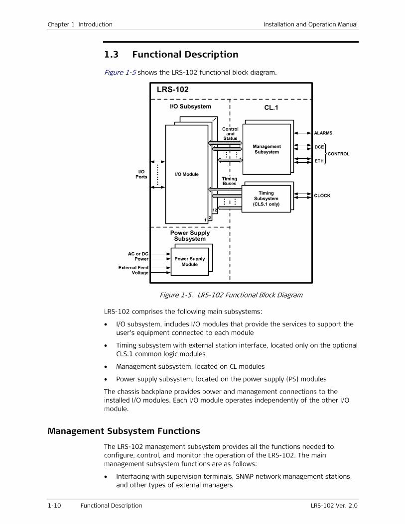
Chapter 1 Introduction Installation and Operation Manual
1-10 Functional Description LRS-102 Ver. 2.0
1.3 Functional Description
Figure 1-5 shows the LRS-102 functional block diagram.
12
2
I/O Module
1
I/O Subsystem
AC or DCPower
TimingBuses
CLOCK
Power SupplyModule
I/OPorts
LRS-102
Power SupplySubsystem
CL.1
DS0Cross-Connect
TimingSubsystem(CLS.1 only)
Controland
Status
ManagementSubsystem
DCE
ETH
ALARMS
CONTROL
External FeedVoltage
Figure 1-5. LRS-102 Functional Block Diagram
LRS-102 comprises the following main subsystems:
• I/O subsystem, includes I/O modules that provide the services to support the user’s equipment connected to each module
• Timing subsystem with external station interface, located only on the optional CLS.1 common logic modules
• Management subsystem, located on CL modules
• Power supply subsystem, located on the power supply (PS) modules
The chassis backplane provides power and management connections to the installed I/O modules. Each I/O module operates independently of the other I/O module.
Management Subsystem Functions
The LRS-102 management subsystem provides all the functions needed to configure, control, and monitor the operation of the LRS-102. The main management subsystem functions are as follows:
• Interfacing with supervision terminals, SNMP network management stations, and other types of external managers
Installation and Operation Manual Chapter 1 Introduction
LRS-102 Ver. 2.0 Functional Description 1-11
• Configuring the LRS-102
• Controlling the LRS-102 system operation
• Monitoring the LRS-102 status, and reading performance monitoring statistics from I/O modules that support such options.
• Performing LRS-102 tests and diagnostics on the I/O modules that support such options.
• Collecting operational history (alarms, events, performance statistics, etc.) The collected information can be read by maintenance personnel through the management link.
A real-time clock provides time stamps for all the collected information.
• Storage of the application software, which determines the capabilities and features provided by the LRS-102. This software can be remotely downloaded and updated through the management link without taking the equipment off-line. The stored software includes both system software, run by the CL module, and software for the other modules installed in the chassis that support internal software downloading.
• Storage of configuration databases. The configuration databases can also be uploaded and downloaded through the management link.
The application software, as well as the configuration databases, are stored in flash memory.
In addition, the management subsystem also enables signaling the LRS-102 alarm status to bay alarm panels or remote operator consoles by means of two sets of dry relay contacts (one for major alarms, the other for minor alarms) included in a dedicated ALARM connector.
As an option, LRS-102 units can also be managed by the RADview EMS, an SNMP-based Element Management System offered by RAD.
Management Support
The LRS-102 supervision and configuration activities can be performed using one of the following methods:
• Supervision terminal (for example, implemented using a PC running ASCII terminal emulation), connected to the serial control port of a CL module. No configuration information need be stored by the terminal
• Telnet hosts (using the same procedures as the supervision terminal utility), The following access options are supported:
Out-of-band access via the dedicated Ethernet management port of the CL module(s).
Inband access through user-configured Ethernet ports terminated on I/O modules, using a dedicated management VLAN
• Management by SNMP-based network management stations, using the access options described above for Telnet hosts. LRS-102 includes an internal SNMP agent that enables full SNMP management by SNMP-based network management stations. The internal agent supports the SNMPv3 authentication and privacy features, with continued support for SNMPv1.
Chapter 1 Introduction Installation and Operation Manual
1-12 Functional Description LRS-102 Ver. 2.0
• Web browsers (using the ConfiguRAD utility run by the LRS-102 management subsystem), using the access options described above for Telnet hosts
Except for the serial control port, all the other management access ports use IP-based communications, where a single IP address (the host IP address) is assigned to the management subsystem. All the ports use the same IP and, when applicable, SNMP management communication parameters, and therefore management traffic can reach the LRS-102 management subsystem through any available access port.
Remote Software and Configuration Updating
The management subsystem supports TFTP for remote software updating and downloading, in addition to cold software downloading using an ASCII terminal directly connected to the LRS-102 (by means of the XMODEM protocol).
TFTP can also be used to upload and download the LRS-102 configuration database. Network administrators can use the download capability to distribute verified configuration files to all the managed LRS-102 units in the network from a central location. To further expedite the process, it is also possible to upload the configuration data stored by an LRS-102 unit to the management station as a disk file, and then distribute this file to other units which use a similar configuration.
Supervisory Port Capabilities
All the LRS-102 supervision and configuration functions, and in particular the preliminary configuration activities, can be performed using a “dumb” ASCII terminal (or a PC running a terminal emulation program) directly connected to the LRS-102 serial RS-232 asynchronous supervisory port, located on its front panel. The terminal is controlled by the program stored in the LRS-102. No information has to be stored in the terminal.
The supervisory port enables performing the preliminary configuration of the LRS-102. After the preliminary configuration is completed, LRS-102 can also be managed by the other means, for example, Telnet hosts and Web browsers.
The supervisory port has a DCE interface, and supports data rates in the range of 9.6 to 115.2 kbps.
Out-of-Band Access via CL Ethernet Management Port
The CL modules have a CONTROL ETH port with a 10BASE-T/100BASE-TX Ethernet interface. This interface supports MDI/MDIX crossover, and therefore the port can always be connected through a “straight” (point-to-point) cable to any other type of 10/100BASE-T Ethernet port (hub or station).
The CL Ethernet management port supports IP communications, using the host IP address of the LRS-102 management subsystem.
The CONTROL ETH ports of both CL modules can be simultaneously connected to the same LAN, through standard Ethernet hubs or switches (see the CL Module Redundancy section below).
To support out-of-band management, management stations, Telnet hosts, etc., can be attached to the same LAN, or to any LAN from which IP communication with the CL module Ethernet ports is possible.
Installation and Operation Manual Chapter 1 Introduction
LRS-102 Ver. 2.0 Functional Description 1-13
CL Module Redundancy
Only one CL module is necessary per chassis, however the chassis has two slots dedicated to this type of module. The second slot can be used to install a redundant CL module of the same type, thereby providing a hot-standby capability for the LRS-102 system control functions.
When a second CL module is installed, the two modules operate as a master/slave pair; one module is the active (online) module, and the other is off-line and serves as a hot standby.
Only the online CL module accepts management communication through its interfaces and actively manages the LRS-102 system. The off-line CL module is automatically updated by the online module with all the configuration and status data, and therefore the off-line can take over at any time without disrupting system operation. The switchover to the off-line module occurs automatically upon detection of failure in the online module, or upon removing the online module from the chassis.
The slave CL module communicates only with the online module. Moreover, the transmit line in the slave supervisory port connector is disabled, to enable physical connection in parallel (e.g., by means of a Y cable) to a supervision terminal or to a modem, and the CL Ethernet port is also disabled, and therefore the Ethernet connectors of the two CL modules can be simultaneously connected to the same LAN.
Performance Monitoring Statistics
LRS-102 management subsystem enables collecting performance data from the I/O modules installed in the chassis, thereby enabling the network operator to monitor the transmission performance and thus the quality of service provided to users, as well as identify transmission problems.
Performance parameters for all the active entities are continuously collected during equipment operation.
Alarm Collection and Reporting
The LRS-102 management subsystem continuously monitors critical signals and signal processing functions on each module installed in the chassis, and also performs automatic self-test upon power-up. If a problem is detected, LRS-102 generates time-stamped alarm messages. The time stamp is provided by an internal real-time clock.
For continuous system monitoring, the user can monitor alarm messages through the supervisory port. Alarm messages can also be automatically sent as traps to the user-specified network management stations.
The alarms can be read on-line by the network administrator using a Telnet host, a Web browser, SNMP-based network management station, or a supervision terminal.
The LRS-102 can also monitor one external sense input, and will report its activation as any other internally-detected alarm.
In addition to the alarm collection and reporting facility, the LRS-102 has two alarm relays with floating change-over contacts: one relay for indicating the presence of major alarms and the other for minor alarms. Each relay changes
Note
Chapter 1 Introduction Installation and Operation Manual
1-14 Functional Description LRS-102 Ver. 2.0
state whenever the first alarm is detected, and returns to its normal state when all the alarms of the corresponding severity disappear. The relay contacts can be used to report internal system alarms to outside indicators, e.g., lights, buzzers, bells, etc., located on a bay alarm or remote monitoring panel.
To expedite the handling of alarms, the user can use several tools:
• Masking of alarm conditions, to prevent continuous reporting of known alarm conditions, e.g., during maintenance activities.
• Inversion of selected alarm indications provided to the local operator by the alarm indicators, and by the two alarm relays. “Inverted” alarms are ignored while they are present, therefore the user will be alerted only upon return to normal operation.
• Filtering of alarms, to prevent unnecessary reporting of alarms during marginal conditions, which cause frequent changes in alarm states.
Diagnostic Functions
LRS-102 management subsystem enables activating the diagnostic functions of the I/O modules installed in the chassis, and thus permits to efficiently locate the problem (in the LRS-102 chassis, one of LRS-102 modules, a connecting cable, or external equipment) and rapidly restore full service.
The diagnostic functions are based on the activation of loopbacks at various ports. These loopbacks enable to identify whether a malfunction is caused by the LRS-102 or by an external system component (for example, an equipment unit, cable, or transmission path connected to the LRS-102). A detailed description of the test and loopback functions is given in Chapter 5, as well as in the Installation and Operation Manuals of each module.
Timing Subsystem
Internal Timing
Each I/O module installed in the LRS-102 chassis has its own independent timing subsystem, with an internal oscillator that can serve as its timing source.
Some modules can also use other internal sources, for example, the recovered clock signal from a selected external E1 or T1 interface of the module (see the Installation and Operation Manual of each I/O module for details).
Station Timing (CLS.1 Modules only)
The optional CLS.1 modules include an external station clock interface, and a timing distribution subsystem that can supply the external clock signal received through the CLS.1 module CLOCK connectors to the LRS-102 I/O slots. The external clock signal is usually provided by a highly-accurate master clock source, which is often available in communication facilities (for example, a signal provided by a GPS-based timing source, an independent primary clock source, clock signals provided by an SDH/SONET ADM, or other suitable clock source). The clock signal frequency is user-selectable: 2.048 MHz, 2048 Mbps, or 1.544 Mbps.
Therefore, as a future option, the user can configure I/O modules that can accept a timing reference signal from the LRS-102 timing distribution subsystem to

Installation and Operation Manual Chapter 1 Introduction
LRS-102 Ver. 2.0 Functional Description 1-15
derive their timing from the external station clock, in addition to the module internal timing options.
This permits hierarchical dissemination of timing throughout the communication systems, and ensures that a reliable, high quality timing source can be used even in case of transmission faults or equipment malfunctions.
Each CLS.1 module can be connected to a separate station clock source, and therefore each module can provide a separate reference signal. Therefore, when both CLS.1 modules are connected to station clock sources, the station clock of CLS.1 module in slot CL-A is automatically selected as the master source, and that of the CLS.1 module in slot CL-B is selected as fallback source.
Station Clock Interface Characteristics (CLS.1 Modules only)
The station clock interface has an ITU-T Rec. G.703 interface. The clock interface (balanced/unbalanced) and sensitivity (long or short range) are user-selectable.
The station clock interface also provides an output clock signal, for chaining applications. The source of the output clock is selectable:
• The external clock signal applied to the station clock interface.
• The external clock signal, after regeneration and filtering by a jitter attenuator (the recommended method)
• When no external clock signal is connected, the station clock interface can output the clock signal generated by an internal oscillator located on the CLS.1 module
The structure of the external clock interface provides a convenient way to distribute clock signals to several equipment units installed in close proximity, e.g., in the same equipment rack. To minimize waveform degradation, it is recommended to use high-quality shielded cables, as short as practical.
Typically, the external clock interface connectors can be simply connected in a daisy-chain configuration. In this case, the clock source is connected to the external clock input in the station clock interface, and serves as the system (nodal) timing reference. The station output clock is configured to use the system timing as reference. The clock signal appearing at the external clock output is connected to the external clock input of the next LRS-102, and so on.
To protect the other equipment, the station clock interface has a bypass relay that connects directly the input line to the output when the LRS-102 is not powered.
Power Supply Subsystem
PS Modules
LRS-102 can be ordered with either AC or DC power supply modules, as listed on page 1-7.
Two PS modules can be installed in the chassis. Only one PS module is required to provide power to a fully equipped LRS-102, and therefore installing a second module provides redundancy. While both modules operate normally, they share the load; in case one fails or does not receive power, the other module continues

Chapter 1 Introduction Installation and Operation Manual
1-16 Functional Description LRS-102 Ver. 2.0
to provide power alone. Switch-over is thus automatic and does not disturb normal operation.
Feed Voltage Sources
LRS-102 PS modules support the connection of an external feed voltage source. The connection is made as follows:
• DC-powered PS modules derive the -48 VDC feed voltage from the DC input voltage. In addition, the power input connector also includes a +72 VDC input. This enables providing a 120 VDC feed voltage to I/O modules that require this capability.
• AC-powered PS modules have a separate connector for two feed voltages.
RAD offers the standalone Ringer-2200N unit, intended for installation in 19” racks, for providing the required feed voltages.
For additional details, refer to the corresponding Installation and Operation Manual.
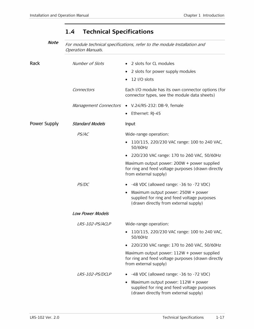
Installation and Operation Manual Chapter 1 Introduction
LRS-102 Ver. 2.0 Technical Specifications 1-17
1.4 Technical Specifications
For module technical specifications, refer to the module Installation and Operation Manuals.
Rack Number of Slots • 2 slots for CL modules
• 2 slots for power supply modules
• 12 I/O slots
Connectors Each I/O module has its own connector options (for connector types, see the module data sheets)
Management Connectors • V.24/RS-232: DB-9, female
• Ethernet: RJ-45
Power Supply Standard Models Input
PS/AC Wide-range operation:
• 110/115, 220/230 VAC range: 100 to 240 VAC, 50/60Hz
• 220/230 VAC range: 170 to 260 VAC, 50/60Hz
Maximum output power: 200W + power supplied for ring and feed voltage purposes (drawn directly from external supply)
PS/DC • -48 VDC (allowed range: -36 to -72 VDC)
• Maximum output power: 250W + power supplied for ring and feed voltage purposes (drawn directly from external supply)
Low Power Models
LRS-102-PS/ACLP Wide-range operation:
• 110/115, 220/230 VAC range: 100 to 240 VAC, 50/60Hz
• 220/230 VAC range: 170 to 260 VAC, 50/60Hz
Maximum output power: 112W + power supplied for ring and feed voltage purposes (drawn directly from external supply)
LRS-102-PS/DCLP • -48 VDC (allowed range: -36 to -72 VDC)
• Maximum output power: 112W + power supplied for ring and feed voltage purposes (drawn directly from external supply)
Note

Chapter 1 Introduction Installation and Operation Manual
1-18 Technical Specifications LRS-102 Ver. 2.0
For PS/DC, the DC input voltage can be floated with respect to LRS-102 ground by means of field-selectable jumpers. Internal jumpers can also be set to match operational requirements that need either the + (positive) or – (negative) terminal of the power source to be grounded. Contact RAD Technical Support Department for detailed information.
For PS/DCLP, the positive DC input pole is permanently connected to the ground conductor.
Physical Height 17.7 cm (7.0 in)
Width 48.2 cm (19.0 in)
Depth 32.4 cm (12.8 in)
Weight • LRS-102 with 1 AC power supply module: 6.9 kg (15.2 lb)
• LRS-102 with 1 DC power supply module: 7.4 kg (16.3 lb)
• LRS-102 with 1 AC and 1 DC power supply modules: 8.6 kg (19.0 lb)
• LRS-102 with 2 AC power supply modules: 8.1 kg (17.8 lb)
• LRS-102 with 2 DC power supply modules: 9.0 kg (19.8 lb)
Environment Temperature 0° to 45°C (32° to 113°F)
Humidity Up to 90%, non-condensing
CL Module
Serial Control Port (CONTROL DCE)
Interface RS-232/V.24 (DCE)
Data Rate 9.6, 19.2, 38.4, 57.6, 115.2 kbps asynchronous
Connector 9-pin, D-type, female
Ethernet Management Port (CONTROL ETH)
Interface 10/100BaseT with autonegotiation
Connector RJ-45
Diagnostics Tests
Alarms • Time and date stamped
• Last 256 alarms stored in RAM on CL module, readable by management system or terminal
• Current alarms status
Caution
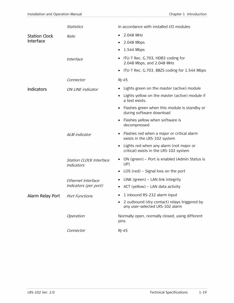
Installation and Operation Manual Chapter 1 Introduction
LRS-102 Ver. 2.0 Technical Specifications 1-19
Statistics In accordance with installed I/O modules
Station Clock Interface
Rate • 2.048 MHz
• 2.048 Mbps
• 1.544 Mbps
Interface • ITU-T Rec. G.703, HDB3 coding for 2.048 Mbps, and 2.048 MHz
• ITU-T Rec. G.703, B8ZS coding for 1.544 Mbps
Connector RJ-45
Indicators ON LINE indicator • Lights green on the master (active) module
• Lights yellow on the master (active) module if a test exists.
• Flashes green when this module is standby or during software download
• Flashes yellow when software is decompressed
ALM indicator • Flashes red when a major or critical alarm exists in the LRS-102 system
• Lights red when any alarm (not major or critical) exists in the LRS-102 system
Station CLOCK Interface Indicators
• ON (green) – Port is enabled (Admin Status is UP)
• LOS (red) – Signal loss on the port
Ethernet Interface Indicators (per port)
• LINK (green) – LAN link integrity
• ACT (yellow) – LAN data activity
Alarm Relay Port Port Functions • 1 inbound RS-232 alarm input
• 2 outbound (dry contact) relays triggered by any user-selected LRS-102 alarm
Operation Normally open, normally closed, using different pins
Connector RJ-45

Chapter 1 Introduction Installation and Operation Manual
1-20 Technical Specifications LRS-102 Ver. 2.0

LRS-102 Ver. 2.0 Site Requirements and Prerequisites 2-1
Chapter 2
Installation and Setup
This Chapter provides installation instructions for the LRS-102.
The Chapter presents the following information:
• General description of equipment enclosure and its panels.
• Mechanical and electrical installation instructions for the enclosure itself and for system modules, that is, PS and CL modules.
After installing the system, it is necessary to configure it in accordance with the specific user's requirements:
• The preliminary system configuration is always performed by means of a supervision terminal (procedures for using the terminal are given in Chapter 3). The software necessary for using the terminal is stored in the CL module: if the CL module is not yet loaded with the required software, refer to Appendix B for detailed software installation instructions.
• After the preliminary configuration, the system can also be managed by means of Telnet hosts, Web browsers, and/or SNMP-based network management stations.
2.1 Site Requirements and Prerequisites
Before connecting this product to a power source, make sure to read the Handling Energized Products section at the beginning of this manual.
LRS-102 PS modules which do not have a power ON/OFF switch start operating as soon as power is applied. Therefore, an external power ON/OFF switch is required (for example, the circuit breaker that protects the power line can also serve as an ON/OFF switch).
AC Power Requirements
AC-powered LRS-102 units should be installed within 1.5m (5 feet) of an easily-accessible grounded AC outlet capable of furnishing 110/115 or 230 VAC, (nominal), 50/60 Hz.
DC Power Requirements
DC-powered LRS-102 units require a -48 VDC (-36 to -72 VDC) power source.
Warning
Caution
Chapter 2 Installation and Setup Installation and Operation Manual
2-2 Site Requirements and Prerequisites LRS-102 Ver. 2.0
For PS/DC and PS/AC modules:
1. Internal jumpers on the PS modules can be set to match operational requirements that need either the + (positive) or – (negative) terminal of the DC power or feed voltage source to be grounded. The normal factory setting is for a source with the +(positive) terminal grounded (the power supply module jumpers are installed in the BGND=FGND and GND=FGND positions). When it is necessary to use a source with the – (negative) terminal grounded, or a floating source, the jumpers must be disconnected (set to NO).
In particular, check the position of jumpers in the PS/DC power supply module (see Figure 2-7) before connecting the supply voltage.
Certain I/O modules may still cause BGND to be connected to FGND or GND, even after setting the jumpers to NO. Refer to the Installation and Operation Manuals of the modules installed in the chassis for proper setting of their ground-control jumpers.
2. If the LRS-102 chassis must be operated with floating ground, it may also be necessary to disconnect the ground reference on the power supply modules, and check the ground and shield wiring on the cables connected to the chassis. This may require replacing the cables with cables suitable to your specific application.
For LRS-102-PS/DCLP modules, the positive DC input terminal is permanently connected to the ground conductor.
LRS-102 chassis must always be connected to FGND (protective ground).
Payload Connection Requirements
For information regarding connections to port types not covered below, refer to the corresponding module Installation and Operation Manual.
Connections to E1 and T1 Ports
LRS-102 systems may be equipped with modules having external E1 and T1 ports. The maximum allowable line attenuation between a LRS-102 port and the network interface depends on the type of port interface, and therefore it is given in the Installation and Operation Manual of each specific module.
The electrical E1 and T1 interfaces of LRS-102 modules must not be connected directly to unprotected public telecommunication networks. Use primary protectors in the MDF or IDF for additional protection.
The balanced E1 and T1 ports located on LRS-102 OP-108C and OP-106C modules are terminated in 44-pin female D-type connectors. RAD offers special adapter cables for terminating the ports in standard RJ-45 connectors (see the module Installation and Operation Manuals).
The balanced interfaces of OP-108C modules can be converted to unbalanced interfaces by means of special adapter cables offered by RAD (see OP-108C Installation and Operation Manual).
When the LRS-102 is equipped with OP-108C/UNBAL modules, LRS-102 must be ordered with the BNC patch panel option, which provides BNC connectors to terminated each unbalanced E1 port.
Caution
Note

Installation and Operation Manual Chapter 2 Installation and Setup
LRS-102 Ver. 2.0 Site Requirements and Prerequisites 2-3
Connections to Optical Ports
Optical ports located on I/O modules have sockets for installing the desired type of SFP transceiver.
RAD offers SFPs that meet a wide range of system requirements, for example, SFPs with 850 or 1310 nm short-haul interfaces for use over multimode fibers, or 1310 and 1550 nm long-haul interfaces for use over single-mode fibers.
SFP transceivers can also be installed in the field, by the customer, however RAD strongly recommends to order modules with preinstalled SFPs, as this enables performing full functional testing of equipment prior to shipping.
Optical Cable Requirements
The cables connected to LRS-102 optical ports should use 2-mm optical fibers terminated in the corresponding type of connectors.
When routing fibers, make sure to observe the minimum bending radius (35 mm). RAD recommends installing plastic supports on each cable connector: these supports determine the fiber bending radius at the connector entry point and also prevent stress at this point.
Connections to Station Clock (Optional – CLS.1 Modules Only)
The station clock port located on the CLS.1 module can accept 2.048 MHz or 1.544 MHz signals (framed 2.048 Mbps or 1.544 Mbps signals are also accepted). The port can also output the clock signal: this output provides a convenient means for distributing the station clock signals to other equipment.
The station clock port is terminated in one RJ-45 connector, designated CLOCK, which supports two interfaces:
• 100 Ω/120 Ω balanced interface for operation over two twisted pairs
• 75 Ω unbalanced interface for operation over coaxial cables. This interface can be used only for 2.048 MHz or 2.048 Mbps clock signals.
At any time, only one interface is active. The selection of the active interface is made automatically. The type cable connected to the port is automatically sensed:
• The cable used for connecting to equipment with balanced interface should include only two twisted pairs, one for the clock output and the other for the clock input.
One of the contacts in the station clock connector is used to sense the connection of the unbalanced adapter cable (see Appendix A). Therefore, do not connect cables with more than two pairs when you want to use the balanced interface.
• To connect to equipment with unbalanced interface, it is necessary to convert the CL RJ-45 connector to the standard pair of BNC female connectors used for unbalanced ITU-T Rec. G.703 interfaces. For this purpose, RAD offers a 15-cm long adapter cable, CBL-RJ45/2BNC/E1/X. This cable has one RJ-45 plug for connection to CLS.1 station clock connector, and two BNC female connectors at the other end.
Note

Chapter 2 Installation and Setup Installation and Operation Manual
2-4 Site Requirements and Prerequisites LRS-102 Ver. 2.0
When using redundant CLS.1 modules and the station clock is used as timing reference, only one of the two station clock ports must be connected to a station clock source. For best protection, it is recommended to connect the two station ports to two separate station clock sources.
Management Connection Requirements
Ethernet Connections to CL Modules
The CL modules have 10BASE-T/100BASE-TX Ethernet interfaces terminated in RJ-45 connectors, designated CONTROL ETH.
These interfaces support MDI/MDIX crossover and therefore the ports can always be connected through a “straight” (point-to-point) cable to any other type of 10/100BASE-T Ethernet port (hub or station).
Connection to Serial Port
The CL supervisory port has a serial RS-232 asynchronous DCE interface terminated in a 9-pin D-type female connector, designated CONTROL DCE.
This port can be directly connected to terminals using a cable wired point-to-point. A cross cable is required to use the DTE mode, for example, for connection through modems or digital multiplexer channels.
When using redundant CL modules, you can connect the terminal, respectively the modem, in parallel to the corresponding serial port connectors of the two modules by means of a simple Y-cable, because at any time only one serial port (that of the active module) is active.
Ethernet ports of redundant CL modules do not require any special connections: each one can be connected to a separate Ethernet hub port.
Connections to Alarm Port
The alarm port is terminated in a 8-pin RJ-45 connector located on the CL module, designated ALARM. This port includes:
• Floating change-over dry-contact outputs for the major and minor alarm relays. The alarm relay contacts are rated at maximum 60 VDC/30 VAC across open contacts, and maximum 1 ADC through closed contacts (total load switching capacity of 60 W).
Protection devices must be used to ensure that the contact ratings are not exceeded. For example, use current limiting resistors in series with the contacts, and place voltage surge absorbers across the contacts.
The relays are controlled by software, and therefore the default state (that is, the state during normal operation) can be selected by the user in accordance with the specific system requirements.
• External alarm sense input. The input accepts an RS-232 input signal.
Caution
Note
Note
Installation and Operation Manual Chapter 2 Installation and Setup
LRS-102 Ver. 2.0 Required Equipment 2-5
Front and Rear Panel Clearance
Allow at least 90 cm (36 inches) of frontal clearance for operator access.
Allow the same clearance at the rear of the unit for interface cable connections and module replacement.
Ambient Requirements
The ambient operating temperature range of the LRS-102 is 0 to +45°C (32 to 113°F), at a relative humidity of up to 90%, non-condensing.
Most of the LRS-102 modules are cooled by free air convection. The power supply modules have a miniature cooling fan installed on their front panels.
Electromagnetic Compatibility Considerations
The LRS-102 is designed to comply with the electromagnetic compatibility (EMC) requirements of Sub-Part J of FCC Rules, Part 15, for Class A electronic equipment, and additional applicable standards.
To meet these standards, it is necessary to perform the following actions:
• Connect the LRS-102 case to a low-resistance grounding system.
• Install blank panels to cover all empty slots. Appropriate blank panels can be ordered from RAD.
• Whenever possible, use shielded telecommunication cables.
Covering all empty slots is also required for reasons of personal safety.
2.2 Package Contents
The LRS-102 package includes the following items:
• LRS-102 unit
• Power cords
• Hardware kit for rack installation (if ordered)
• Technical documentation CD.
Modules are shipped either separately, or preinstalled in the chassis, in accordance with your order.
2.3 Required Equipment
The cables you need to connect to the LRS-102 depend on your specific application. You can prepare the appropriate cables yourself in accordance with the information given in Appendix A, or order cables from RAD.
Warning
Chapter 2 Installation and Setup Installation and Operation Manual
2-6 Mounting the LRS-102 Unit LRS-102 Ver. 2.0
For information regarding the cables needed to connect to LRS-102 I/O modules, refer to the module Installation and Operation Manuals.
2.4 Mounting the LRS-102 Unit
This section presents instructions for installing LRS-102 units. To help you familiarize with the equipment, it also presents a physical description of the LRS-102 versions.
Safety Precautions
No internal settings, adjustment, maintenance, and repairs may be performed by either the operator or the user; such activities may be performed only by a skilled technician who is aware of the hazards involved. Always observe standard safety precautions during installation, operation, and maintenance of this product.
LRS-102 modules contain components sensitive to electrostatic discharge (ESD). To prevent ESD damage, always hold the module by its sides, and do not touch the module components or connectors.
Delicate electronic components are installed on both sides of the printed circuit boards (PCBs) of the LRS-102 modules. To prevent physical damage:
• Always keep modules in their protective packaging until installed in the LRS-102 chassis, and return them to the packaging as soon as they are removed from the enclosure.
• Do not stack modules one above the other, and do not lay any objects on PCBs.
• When inserting a module into its chassis slot, align it carefully with the chassis slot guides, and then push it in gently. Make sure the module PCB does not touch the adjacent module, nor any part of the chassis. If resistance is felt before the module fully engages the mating backplane connector, retract the module, realign it with the slot guides and then insert again.
Grounding
For your protection and to prevent possible damage to equipment when a fault condition, e.g., a lightning stroke or contact with high-voltage power lines, occurs on the lines connected to the equipment, the LRS-102 case must be properly grounded (earthed) at any time. Any interruption of the protective (grounding) connection inside or outside the equipment, or the disconnection of the protective ground terminal can make this equipment dangerous. Intentional interruption is prohibited.
Warning
Caution
Caution
Grounding
Installation and Operation Manual Chapter 2 Installation and Setup
LRS-102 Ver. 2.0 Mounting the LRS-102 Unit 2-7
Dangerous voltages may be present on the electrical cables connected to the LRS-102 and its modules.
• Never connect cables to LRS-102 if not properly installed and grounded.
• Disconnect all the cables connected to the electrical connectors of the LRS-102 before disconnecting its grounding connection.
Before connecting any other cable and before applying power to this equipment, the protective ground (earth) terminal of the equipment must be connected to protective ground. LRS-102 grounding terminals are located on the LRS-102 PS module panels.
Whenever LRS-102 units are installed in a rack, make sure that the rack is properly grounded and connected to a reliable, low-resistance grounding system, because the rack can also provide a connection to ground.
In addition, the grounding connection is also made through each one of the AC power cables. Therefore, the AC power cable plug must always be inserted in a socket outlet provided with a protective ground.
Protection against ESD
An electrostatic discharge occurs between two objects when an object carrying static electrical charges touches, or is brought near enough, the other object.
Static electrical charges appear as result of friction between surfaces of insulating materials, separation of two such surfaces and may also be induced by electrical fields. Routine activities such as walking across an insulating floor, friction between garment parts, friction between objects, etc., can easily build charges up to levels that may cause damage, especially when humidity is low.
LRS-102 modules contain components sensitive to electrostatic discharge (ESD). To prevent ESD damage, always hold a module by its sides, and do not touch the module components or connectors. If you are not using a wrist strap, before touching a module, it is recommended to discharge the electrostatic charge of your body by touching the frame of a grounded equipment unit.
Whenever feasible, during installation works use standard ESD protection wrist straps to discharge electrostatic charges. It is also recommended to use garments and packaging made of antistatic materials or materials that have high resistance, yet are not insulators.
Proper Handling of Modules
LRS-102 modules include small components installed on both sides of the printed circuit boards. These components are exposed as long as the modules are not installed in the chassis, are therefore may be unintentionally damaged. To prevent physical damage to modules:
1. Always keep the modules in their protective shipping containers until installed in the chassis. These containers also protect against ESD.
Warning
Caution

Chapter 2 Installation and Setup Installation and Operation Manual
2-8 Mounting the LRS-102 Unit LRS-102 Ver. 2.0
2. Avoid piling up modules.
3. While inserting modules in their chassis slots, support the modules and make sure their components do not touch the chassis structure, nor other modules while sliding into position.
Do not connect any cables to the LRS-102 before it is installed in the designated position.
Familiarization with LRS-102
Figure 2-1 shows a general view of the LRS-102 enclosure. Instead of the standard front panel shown in Figure 2-1.A , LRS-102 can also be ordered with a patch panel with BNC connectors (Figure 2-1.B), to support unbalanced E1 interfaces, for example, those of OP-108C/UNBAL modules.
Enclosure with Standard Panel
Warning

Installation and Operation Manual Chapter 2 Installation and Setup
LRS-102 Ver. 2.0 Mounting the LRS-102 Unit 2-9
Enclosure with Optional BNC Patch Panel
Figure 2-1. LRS-102 Enclosure, General Views
The enclosure has 16 module slots: two of them are reserved for PS modules, and two for CL modules. The other 12 slots are intended for I/O modules. Each I/O slot can accept any type of I/O module. The modules are inserted from the rear side.
The LRS-102 enclosure can be ordered with brackets for installation in racks. The brackets are attached to the sides of the enclosure, near the front or rear panel.
Rear View
Figure 2-2 shows a typical rear view of the LRS-102 enclosure and identifies the slots and their use. Note the labels which designate the type of module that can be installed in each slot; in addition, each slot is keyed, therefore it is not possible to install the wrong module type.
To prevent physical damage to the electronic components assembled on the two sides of the module printed circuit boards (PCB) while it is inserted into its chassis slot, support the module while sliding it into position and make sure that its components do not touch the chassis structure, nor other modules.
Caution
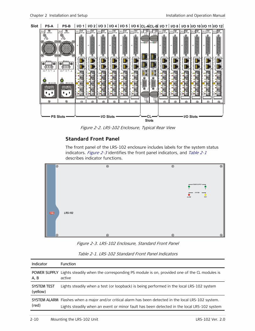
Chapter 2 Installation and Setup Installation and Operation Manual
2-10 Mounting the LRS-102 Unit LRS-102 Ver. 2.0
E1
LASERCLASS
1
OP
A
OPA
OPB
ACT
1
2OP
B
ETH
AIS
SYNCLOS
2
1
3
4
TXR
XTX
RXTX
RXTX
RX
E1
LASERCLASS
1
OP
A
OPA
OPB
ACT
1
2OP
B
ETH
AIS
SYNCLOS
2
1
3
4
TXR
XTX
RXTX
RXTX
RX
E1
LASERCLASS
1
OP
A
OPA
OPB
ACT
1
2OP
B
ETH
AIS
SYNCLOS
2
1
3
4
TXR
XTX
RXTX
RXTX
RX
E1
LASERCLASS
1
OP
A
OPA
OPB
ACT
1
2OP
B
ETH
AIS
SYNCLOS
2
1
3
4
TXR
XTX
RXTX
RXTX
RX
E1
LASERCLASS
1
OP
A
OPA
OPB
ACT
1
2OP
B
ETH
AIS
SYNCLOS
2
1
3
4
TXR
XTX
RXTX
RXTX
RX
OP-108C
E1
LASERCLASS
1
OP
A
OPA
OPB
ACT
1
2OP
B
ETH
AIS
SYNCLOS
2
1
3
4
TXR
XTX
RXTX
RXTX
RX
OP-108COP-108COP-108COP-108COP-108C
E1
LASERCLASS
1
OP
A
OPA
OPB
ACT
1
2OP
B
ETH
AIS
SYNCLOS
2
1
3
4
TXRX
TXRX
TXRX
TXRX
E1
LASERCLASS
1
OP
A
OPA
OPB
ACT
1
2OP
B
ETH
AIS
SYNCLOS
2
1
3
4TX
RXTX
RXTX
RXTX
RX
E1
LASERCLASS
1
OP
A
OPA
OPB
ACT
1
2OP
B
ETH
AIS
SYNCLOS
2
1
3
4
TXRX
TXRX
TXRX
TXRX
E1
LASERCLASS
1
OP
A
OPA
OPB
ACT
1
2OP
B
ETH
AIS
SYNCLOS
2
1
3
4
TXRX
TXRX
TXRX
TXRX
E1
LASERCLASS
1
OP
A
OPA
OPB
ACT
1
2OP
B
ETH
AIS
SYNCLOS
2
1
3
4
TXRX
TXRX
TXRX
TXRX
OP-108C
E1
LASERCLASS
1
OP
A
OPA
OPB
ACT
1
2OP
B
ETH
AIS
SYNCLOS
2
1
3
4
TXRX
TXRX
TXRX
TXRX
OP-108COP-108COP-108COP-108COP-108C
PS Slots
PS-ASlot PS-B I/O 1 I/O 2 I/O 3 I/O 4 I/O 5 I/O 6 I/O 7 I/O 8 I/O 9 I/O 10 I/O 11 I/O 12CL-ACL-B
CL Slots
I/O Slots I/O Slots
PS-B I/O 1 I/O 2 I/O 3 I/O 4 I/O 5 I/O 6 I/O 9 I/O 10 I/O 11 I/O 12CL-A CL-BPS-A
5A T 250V
ON
POWER
LRS-PS/AC
RTN -48+72
VDC-IN
5A T 250V
ON
POWER
LRS-PS/AC
RTN -48+72
VDC-IN
ONLINE ALM
ALARM
DCE
LOS
ON
CLOCK
ACT
LINK
CONTROL
ONLINE ALM
ALARM
DCE
LOS
ON
CLOCK
ACT
LINK
CONTROL
ETH ETH
Figure 2-2. LRS-102 Enclosure, Typical Rear View
Standard Front Panel
The front panel of the LRS-102 enclosure includes labels for the system status indicators. Figure 2-3 identifies the front panel indicators, and Table 2-1 describes indicator functions.
LRS-102
POWER SUPPLY
SYST EM
AL ARM
A
TEST
B
Figure 2-3. LRS-102 Enclosure, Standard Front Panel
Table 2-1. LRS-102 Standard Front Panel Indicators
Indicator Function
POWER SUPPLY
A, B
Lights steadily when the corresponding PS module is on, provided one of the CL modules is
active
SYSTEM TEST
(yellow)
Lights steadily when a test (or loopback) is being performed in the local LRS-102 system
SYSTEM ALARM
(red)
Flashes when a major and/or critical alarm has been detected in the local LRS-102 system.
Lights steadily when an event or minor fault has been detected in the local LRS-102 system
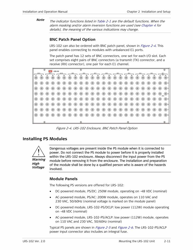
Installation and Operation Manual Chapter 2 Installation and Setup
LRS-102 Ver. 2.0 Mounting the LRS-102 Unit 2-11
The indicator functions listed in Table 2-1 are the default functions. When the alarm masking and/or alarm inversion functions are used (see Chapter 4 for details), the meaning of the various indications may change.
BNC Patch Panel Option
LRS-102 can also be ordered with BNC patch panel, shown in Figure 2-4. This panel enables connecting to modules with unbalanced E1 ports.
The patch panel has 12 sets of BNC connectors, one set for each I/O slot. Each set comprises eight pairs of BNC connectors (a transmit (TX) connector, and a receive (RX) connector), one pair for each E1 channel.
LRS-102
1
2
3
4
5
6
7
8
TX RX
I/O 1
TX RX
I/O 2OP A
OP B
TX RX
I/O 3
TX RX
I/O 4
TX RX
I/O 5
TX RX
I/O 6
TX RX
I/O 7
TX RX
I/O 8
TX RX
I/O 9
TX RX
I/O 10
TX RX
I/O 11
TX RX
I/O 12
Figure 2-4. LRS-102 Enclosure, BNC Patch Panel Option
Installing PS Modules
Dangerous voltages are present inside the PS module when it is connected to power. Do not connect the PS module to power before it is properly installed within the LRS-102 enclosure. Always disconnect the input power from the PS module before removing it from the enclosure. The installation and preparation of the module shall be done by a qualified person who is aware of the hazards involved.
Module Panels
The following PS versions are offered for LRS-102:
• DC-powered module, PS/DC: 250W module, operating on -48 VDC (nominal)
• AC-powered module, PS/AC: 200W module, operates on 110 VAC and 230 VAC, 50/60Hz (nominal voltage is marked on the module panel)
• DC-powered module, LRS-102-PS/DCLP: low power (112W) module operating on -48 VDC (nominal)
• AC-powered module, LRS-102-PS/ACLP: low power (112W) module, operates on 110 VAC and 230 VAC, 50/60Hz (nominal)
Typical PS panels are shown in Figure 2-5 and Figure 2-6. The LRS-102-PS/ACLP power input connector also includes an integral fuse.
Warning High Voltage
Note
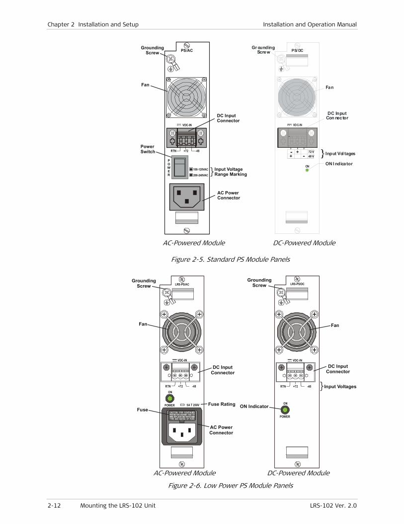
Chapter 2 Installation and Setup Installation and Operation Manual
2-12 Mounting the LRS-102 Unit LRS-102 Ver. 2.0
GroundingScrew
Fan
DC InputConnector
AC PowerConnector
Input VoltageRange Marking
PowerSwitch
PS/AC
VDC-IN
RTN +72 -48
100-120VAC
200-240VAC
POWER
Gr oundingScrew
Fan
DC InputCon nector
ON I ndicator
PS/ DC
VDC-IN
72V48V
- + -
+
ON
Input Vol tages
AC-Powered Module DC-Powered Module
Figure 2-5. Standard PS Module Panels
5A T 250V
ON
POWER
GroundingScrew
Fan
DC InputConnector
AC PowerConnector
Fuse RatingFuse
LRS-PS/AC
RTN -48+72
VDC-IN
ON
POWER
GroundingScrew
DC InputConnector
ON Indicator
Input Voltages
LRS-PS/DC
RTN -48+72
VDC-IN
AC-Powered Module DC-Powered Module
Figure 2-6. Low Power PS Module Panels
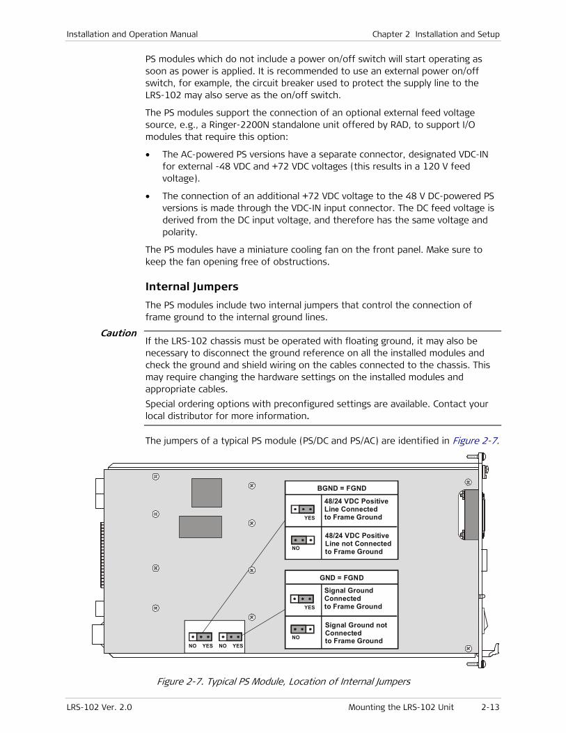
Installation and Operation Manual Chapter 2 Installation and Setup
LRS-102 Ver. 2.0 Mounting the LRS-102 Unit 2-13
PS modules which do not include a power on/off switch will start operating as soon as power is applied. It is recommended to use an external power on/off switch, for example, the circuit breaker used to protect the supply line to the LRS-102 may also serve as the on/off switch.
The PS modules support the connection of an optional external feed voltage source, e.g., a Ringer-2200N standalone unit offered by RAD, to support I/O modules that require this option:
• The AC-powered PS versions have a separate connector, designated VDC-IN for external -48 VDC and +72 VDC voltages (this results in a 120 V feed voltage).
• The connection of an additional +72 VDC voltage to the 48 V DC-powered PS versions is made through the VDC-IN input connector. The DC feed voltage is derived from the DC input voltage, and therefore has the same voltage and polarity.
The PS modules have a miniature cooling fan on the front panel. Make sure to keep the fan opening free of obstructions.
Internal Jumpers
The PS modules include two internal jumpers that control the connection of frame ground to the internal ground lines.
If the LRS-102 chassis must be operated with floating ground, it may also be necessary to disconnect the ground reference on all the installed modules and check the ground and shield wiring on the cables connected to the chassis. This may require changing the hardware settings on the installed modules and appropriate cables.
Special ordering options with preconfigured settings are available. Contact your local distributor for more information.
The jumpers of a typical PS module (PS/DC and PS/AC) are identified in Figure 2-7.
GND = FGND
Signal GroundConnectedto Frame GroundYES
NO
Signal Ground notConnectedto Frame Ground
BGND = FGND
48/24 VDC PositiveLine Connectedto Frame GroundYES
NO
48/24 VDC PositiveLine not Connectedto Frame Ground
NO YES NO YES
Figure 2-7. Typical PS Module, Location of Internal Jumpers
Caution

Chapter 2 Installation and Setup Installation and Operation Manual
2-14 Mounting the LRS-102 Unit LRS-102 Ver. 2.0
• Jumper designated GND=FGND. This jumper controls the connection between the internal signal ground and the frame (enclosure) ground. The module is normally delivered with the jumper set to YES. If necessary, you can set the jumper to NO to float the signal ground with respect to the frame ground.
• Jumper designated BGND=FGND. This jumper controls the connection between the positive (+) line of the external 48 VDC voltage and the frame (enclosure) ground. The module is normally delivered with the jumper set to YES. If necessary, you can set the jumper to NO to float the external 48 VDC positive line with respect to the frame ground.
PS/DC and PS/AC modules can also use a positive supply voltage. In this case, always disconnect BGND from FGND (set the jumper to NO).
If two power supply modules are installed, make sure that the internal jumpers are set to the same position on both modules.
Certain I/O modules may still cause BGND to be connected to FGND or GND, even after setting the jumpers to NO. Refer to the Installation and Operation Manuals of the modules installed in the chassis for proper setting of their ground-control jumpers.
Installing a PS Module
Do not connect the power and/or feed voltage cable(s) to a PS module before it is inserted in the LRS-102 chassis, and disconnect the cable(s) from the module before it is removed from the chassis.
1. Insert the PS module in the PS-A slot, and fasten it with the two screws.
2. Connect the power cable.
3. If an additional redundant module is used, install it in the PS-B slot.
You can install a redundant module in an operating enclosure without turning the LRS-102 power off. In this case:
• First insert the module in its slot
• Connect its power cable.
Removing a PS Module
1. Disconnect the power cable(s) connected to the module.
2. Release the two module screws.
3. Pull the PS module out.
Installing CL Modules
Module Panels
The LRS-102 chassis can be equipped with two CL modules of the same type. At any time, only one module is active, and the other serves as hot standby.
Note
Note
Caution
Warning

Installation and Operation Manual Chapter 2 Installation and Setup
LRS-102 Ver. 2.0 Mounting the LRS-102 Unit 2-15
When only one CL module is installed in the chassis, it must always be installed in slot CL-A.
Moreover, if CL module B is programmed, CL module A must also be programmed in the chassis.
Figure 2-8 shows the CL module panels. Table 2-2 describes the functions of the panel components.
ETH
CL.1
ONLINE ALM
ALARM
DCE
ACT
LINK
CONTROL
ETH
ONLINE ALM
ALARM
DCE
LOS
ON
CLOCK
ACT
LINK
CONTROL
CL.1 Module CLS.1 Module (Optional)
Figure 2-8. CL Module Panels
Note

Chapter 2 Installation and Setup Installation and Operation Manual
2-16 Mounting the LRS-102 Unit LRS-102 Ver. 2.0
Table 2-2. Module CL, Panel Components
Item Function
ON LINE Indicator During normal operation, provides the following indications:
• Lights steadily in green on the master (active) CL module, and flashes slowly
in green on the standby module
• Lights steadily in yellow on the master (active) CL module if a test is active on
the LRS-102.
During software downloading, provides the following indications:
• Flashes in green during software downloading to the CL module
• Flashes in yellow while software is decompressed after downloading
ALM Indicator During normal operation, the ALM indicator of the master CL module provides
the following indications (see also NOTE below):
• Flashes when a major or critical alarm (according to user’s configuration) has
been detected in the local LRS-102.
• Lights steadily when alarms have been detected in the local LRS-102, but the
highest alarm severity (according to user’s configuration) does not exceed
minor.
On the standby CL module, this indicator is always off, even while an alarm
condition is present
CLOCK Connector
(CLS.1 modules only)
RJ-45 connector for the station clock input and output signals. Connector pin
allocation is given in Appendix A.
The built-in indicators provide the following indications:
ON Indicator Lights in green when the station clock port is configured as connected
LOS Indicator Lights in red to indicate a loss-of-signal condition at the station clock port, when
configured as connected
ALARM Connector RJ-45 connector, for connection to the LRS-102 alarm relay outputs, and an
external alarm input. Connector pin allocation is given in Appendix A
CONTROL ETH Connector RJ-45 connector for the CL 10/100BASE-T Ethernet management port. Connector
pin allocation is given in Appendix A.
The built-in indicators provide the following indications:
LINK Indicator Lights steadily in green when the link integrity signal is detected by this port
(normal operating condition – means that the port is connected to an active
Ethernet hub or switch)
ACT Indicator Port activity indicator, lights in yellow when this port transmits and/or receives
data
CONTROL DCE Connector 9-pin D-type female connector with RS-232 DCE interface, for connection to
system management. Connector pin allocation is given in Appendix A
The ALM indicator functions listed in Table 2-2 are the default functions. When the alarm masking and/or alarm inversion functions are used (see Chapter 4 for details), the meaning of the various indications may change.
Note

Installation and Operation Manual Chapter 2 Installation and Setup
LRS-102 Ver. 2.0 Mounting the LRS-102 Unit 2-17
Installing a CL Module
CL modules are installed in the CL-A and/or CL-B slots (see also Note on page 2-15). When two CL modules are installed, redundancy is available. In this case, the module installed in slot CL-A will be automatically selected as the master module, provided that it operates normally and stores all the required configuration parameters.
To install a CL module:
1. Check that the two fastening screws of the module are free to move.
2. Insert the CL module in its chassis slot, and slide it backward as far as it goes.
3. Simultaneously press the extractor handles toward the center of the module to fully insert its rear connector into the mating connector on the backplane.
4. Secure the CL module by tightening its two screws.
Removing a CL Module
To remove a CL module:
1. Fully release the two screws fastening the module to the chassis.
2. Simultaneously push the extractor handles outward, to disengage the rear connector.
3. Pull the module out.
Replacing a CL Module During Equipment Operation - LRS-102 Chassis with two CL Modules
In a LRS-102 equipped with two good CL modules, the standby module can be removed/replaced with minimal disruption of LRS-102 services: when you replace the on-line CL module, the LRS-102 will automatically switch to the standby module, provided that module is OK.
You can identify the active and standby modules by their ON LINE indicators.
To prevent service disruption, check that the ON LINE indicator of the CL module you want to remove is flashing. If not, use the supervisory terminal (or any other management facility) to reset the module to be replaced, and wait for execution of this command before continuing: this will cause the LRS-102 to flip to the other CL module within 50 msec.
To flip to the other CL module using the supervision terminal:
1. Identify the on-line CL module: this is the module with the lit ON LINE indicator.
2. Whenever possible, connect the supervision terminal directly to the CONTROL DCE connector of the on-line CL module, and log in as administrator.
3. Use the Configuration > System > Reset Device screen to send a reset command to the module to be replaced.
Caution
Chapter 2 Installation and Setup Installation and Operation Manual
2-18 Mounting the LRS-102 Unit LRS-102 Ver. 2.0
4. Wait for the flipping to be executed. After it is executed, the ON LINE indicator of the CL module the supervision terminal is connected to starts flashing, while that of the other module stops flashing and lights steadily.
The command will not be executed if a fault is detected in the module that is to become the on-line module. In this case, the ON LINE indicators state will not change.
5. You can now disconnect the supervision terminal, and remove the module.
6. After installing again a CL module in the slot of the removed module, you may cause flipping to the original module by resetting the current on-line CL module.
Replacing a CL Module During Equipment Operation - LRS-102 Chassis with Single CL Module
If the only CL module in the chassis is replaced, LRS-102 services may be disrupted to some extent while no CL module is present. Therefore, be prepared and perform the replacement as rapidly as possible.
In a LRS-102 equipped with a single CL module, before replacing the CL module it is recommended that a good CL module of the same type be installed in the free CL slot. The replacement can be temporary.
In this case, after inserting the additional CL module, first it is necessary to let it update its database from the information provided by the existing CL module:
1. If necessary, program the additional module in the LRS-102 database.
2. Enter the database update command, %, and then wait until the alarm CL DB CHECKSUM IS DIFFERENT is off.
3. At this stage, continue in accordance with the steps listed above for a LRS-102 with two CL modules.
Among other steps, make sure to upload the existing configuration database to a host, using TFTP. After replacement is completed, download the database to the new CL module, to continue normal operation in accordance with the previous configuration.
Installing I/O Modules
Install each I/O module in the prescribed I/O slot, in accordance with the installation plan.
For installation instructions, refer to the corresponding I/O module Installation and Operation Manual.
Installing Blank Panels
Install blank panels in all the chassis slots that are not occupied by modules.
Note
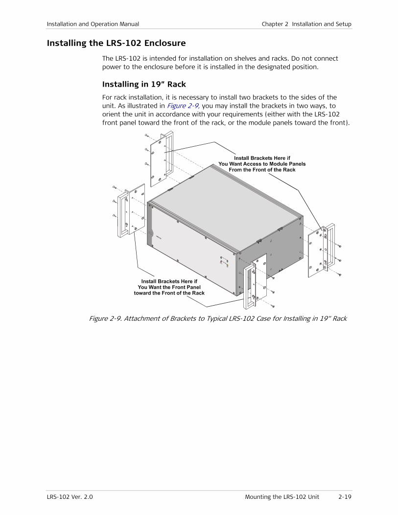
Installation and Operation Manual Chapter 2 Installation and Setup
LRS-102 Ver. 2.0 Mounting the LRS-102 Unit 2-19
Installing the LRS-102 Enclosure
The LRS-102 is intended for installation on shelves and racks. Do not connect power to the enclosure before it is installed in the designated position.
Installing in 19” Rack
For rack installation, it is necessary to install two brackets to the sides of the unit. As illustrated in Figure 2-9, you may install the brackets in two ways, to orient the unit in accordance with your requirements (either with the LRS-102 front panel toward the front of the rack, or the module panels toward the front).
Install Brackets Here ifYou Want the Front Panel
toward the Front of the Rack
Figure 2-9. Attachment of Brackets to Typical LRS-102 Case for Installing in 19” Rack

Chapter 2 Installation and Setup Installation and Operation Manual
2-20 Connecting to LRS-102 LRS-102 Ver. 2.0
Installing in 23” Rack
The same set of brackets used for 19” racks can also be used to install the LRS-102 unit in a 23” rack. Figure 2-10 shows how to attach the brackets for installation in 23” racks (only front installation is shown in this figure).
Figure 2-10. Attachment of Brackets to Typical LRS-102 Case for Installing in 23” Rack
After attaching the brackets, fasten the enclosure to the rack by four screws (two on each side).
After installing the enclosure, check and install the required modules, in accordance with the installation plan.
2.5 Connecting to LRS-102
Grounding the LRS-102
Before connecting any cables and before switching on this instrument, the protective ground terminals of this instrument must be connected to the protective ground conductor of the (mains) power cord. The mains plug shall only be inserted in a socket outlet provided with a protective ground contact. Any interruption of the protective (grounding) conductor (inside or outside the instrument) or disconnecting the protective ground terminal can make this instrument dangerous. Intentional interruption is prohibited. Make sure that only fuses of the required rating are used for replacement. The use of repaired fuses and the short-circuiting of fuse holders is forbidden. Whenever it is likely that the protection offered by fuses has been impaired, the instrument must be made inoperative and be secured against any unintended operation.
Warning
Installation and Operation Manual Chapter 2 Installation and Setup
LRS-102 Ver. 2.0 Connecting to LRS-102 2-21
Connect a short, thick copper braid between the grounding screw on each PS module panel and a nearby grounding point.
Connecting to Power
LRS-102 does not have a power on/off switch. Therefore, when LRS-102 is equipped with PS modules without power on/off switch, it will start operating as soon as power is applied to at least one of its PS modules. It is recommended to use an external power on/off switch to control the connection of power to the LRS-102. For example, the circuit breaker used to protect the supply line to the LRS-102 may also serve as the on/off switch.
Power should be connected only after completing cable connections.
Connect the power cable(s) first to the connector on the PS module, and then to the power outlet. For DC cables, pay attention to polarity.
When redundant power supply modules are used, it is recommended to connect the power cables to outlets powered by different circuits.
Connecting to External Feed Voltages
When modules that require up to 120 V feed voltage are installed in the LRS-102, the recommended source for external voltages is the Ringer-2200N offered by RAD. The Ringer-2200N is a standalone unit intended for rack mounting, capable of providing power for up to twenty DSL channels. Refer to the Ringer-2200N Installation and Operation Manual for connection instructions.
Connecting to CL Module Management and Supervision Ports
To connect to the CONTROL DCE port:
The connections to the CONTROL DCE connector are made as follows:
• Connection to a supervision terminal with 9-pin connector: by means of a straight cable (a cable wired point-to-point).
• Connection to modem with 9-pin connector (for communication with remote supervision terminal): by means of a crossed cable.
Additional connection options are presented in Appendix A.
To connect to a Telnet host, SNMP network management station, or Web browser:
The link to Telnet hosts, SNMP network management station, and/or Web browsers is made to the RJ-45 connector designated CONTROL ETH.
You can use any standard cable (straight or crossed) to connect to any type of Ethernet port (hub or station).
Note
Caution
Chapter 2 Installation and Setup Installation and Operation Manual
2-22 Connecting to LRS-102 LRS-102 Ver. 2.0
To connect to the ALARM connector:
The connection to the ALARM connector is made by means of a cable provided by the customer, in accordance with the specific requirements of each site. Refer to Appendix A for connector pin functions.
To prevent damage to the internal alarm relay contacts, it is necessary to limit, by external means, the maximum current that may flow through the contacts (maximum allowed current through closed contacts is 1A). The maximum voltage across the open contacts must not exceed 60 VDC.
Connecting to the CLOCK Connector (CLS.1 Modules only)
At any time, only one station clock interface is active.
To connect to the balanced clock interface:
The connection to the balanced clock interface in the CLOCK connector is made by means of a cable provided by the customer, in accordance with the specific requirements of each site. Refer to Appendix A for connector pin functions.
To connect to the unbalanced clock interface (relevant only when using the 2.048 Mbps clock sources):
1. Connect the RJ-45 of the adapter cable, CBL-RJ45/2BNC/E1/X, to the CLOCK connector.
2. Use two 75 Ω coaxial cables to connect your equipment to the two BNC plugs at the other end of the CBL-RJ45/2BNC/E1/X cable. Pay attention to the function of each connector: the red plug is the transmit output, and the green is the receive input.
Caution
Note
Installation and Operation Manual Chapter 2 Installation and Setup
LRS-102 Ver. 2.0 Connecting to LRS-102 2-23
Connecting Cables to Optical Ports
Laser Safety
LRS-102 modules may be equipped with a laser diode. In such cases, a label with the laser class and other warnings as applicable will be attached near the optical transmitter. The laser warning symbol may be also attached.
For your safety:
• Before turning on the equipment, make sure that the fiber optic cable is intact and is connected to the optical transmitter.
• Do not use broken or unterminated fiber-optic cables/connectors.
• Do not look straight at the laser beam, and do not directly into the optical connectors while the unit is operating.
• Do not attempt to adjust the laser drive current.
• The use of optical instruments with this product will increase eye hazard. Laser power up to 1 mW could be collected by an optical instrument.
• Use of controls or adjustment or performing procedures other than those specified herein may result in hazardous radiation exposure.
ATTENTION: The laser beam may be invisible!
LRS-102 modules equipped with laser devices provided by RAD comply with laser product performance standards set by governmental agencies for Class 1 laser products. The modules do not emit hazardous light, and the beam is totally enclosed during all operating modes of customer operation and maintenance.
In some cases, the users may insert their own SFP laser transceivers into LRS-102 modules. Users are alerted that RAD cannot be held responsible for any damage that may result if non-compliant transceivers are used. In particular, users are warned to use only agency approved products that comply with the local laser safety regulations for Class 1 laser products.
Wherever applicable, LRS-102 modules are shipped with protective covers installed on all the optical connectors. Do not remove these covers until you are ready to connect optical cables to the connectors. Keep the covers for reuse, to reinstall the cover over the optical connector as soon as the optical cable is disconnected.
Connection Instructions
The optical fibers intended for connection to modules of a LRS-102 installed in a rack should pass through fiber spoolers, located at the top or bottom of the rack, in accordance with the site routing arrangements (overhead or under-the-floor routing). The spoolers must contain enough fiber for routing within the rack up to the corresponding module optical connectors, and for fiber replacement in case of damage (splicing repairs).
From the spoolers, the optical fibers should be routed through cable guides running along the sides of the rack frame to the level of the equipment to which they connect.
When connecting optical cables, make sure to prevent cable twisting and avoid sharp bends (unless otherwise specified by the optical cable manufacturer, the
Warning
Chapter 2 Installation and Setup Installation and Operation Manual
2-24 Connecting to LRS-102 LRS-102 Ver. 2.0
minimum fiber bending radius is 35 mm). Always leave some slack, to prevent stress. RAD recommends installing plastic supports on each cable connector: these supports determine the fiber bending radius at the connector entry point and also prevent stress at this point.
Make sure all the optical connectors are closed at all times by the appropriate protective caps, or by the mating cable connector.
Do not remove the protective cap until an optical fiber is connected to the corresponding connector, and immediately install a protective cap after a cable is disconnected.
Before installing optical cables, it is recommended to clean thoroughly their connectors using an approved cleaning kit.
To connect optical cables to LRS-102 optical ports:
1. For each optical interface, refer to the site installation plan and identify the cables intended for connection to the SFP serving the corresponding interface.
2. Where two fibers are used, pay attention to TX and RX connections, and leave enough slack to prevent strain:
Connect the prescribed transmit fiber (connected to the receive input of the remote equipment) to the TX connector of the SFP.
Connect the prescribed receive fiber (connected to the transmit output of the remote equipment) to the RX connector of the SFP serving the same interface.
Connecting Coaxial Cables to LRS-102 Patch Panel
The optional BNC patch panel offered by RAD for connecting to the links of modules with unbalanced E1 interfaces is equipped with two BNC connectors for each channel.
To connect coaxial cables to the patch panel:
1. For each electrical interface, identify the cables intended for connection to this interface in accordance with the site installation plan.
2. Connect the prescribed coaxial transmit cable (connected to the receive input of the remote equipment) to the TX connector of the interface.
3. Connect the prescribed coaxial receive cable (connected to the transmit output of the remote equipment) to the RX connector of the same interface.
Connecting to LRS-102 I/O Modules
Refer to corresponding module Installation and Operation Manual.
Caution

LRS-102 Ver. 2.0 Turning LRS-102 On 3-1
Chapter 3
Operation
This Chapter provides general operating instructions and preliminary configuration instructions for LRS-102 units.
The information presented in this Chapter is organized as follows:
• Turning on: Section 3.1
• Indications: Section 3.2
• Default settings: Section 3.3
• Configuration and management alternatives for LRS-102: Section 3.4
• Turning off: Section 3.5
3.1 Turning LRS-102 On
When turning the LRS-102 on, it is useful to monitor the power-up sequence.
You can monitor the power-up sequence using any standard ASCII terminal (dumb terminal or personal computer emulating an ASCII terminal) equipped with an RS-232 communication interface (same terminal that can be used to control the LRS-102 operation).
To monitor the LRS-102:
1. Configure the terminal for 115.2 kbps, one start bit, eight data bits, no parity, and one stop bit.
2. Select the full-duplex mode, echo off, and disable any type of flow control. Make sure to use VT-100 terminal emulation: using a different terminal type will cause display problems, for example, the cursor will not be located at the proper location, text may appear jumbled, etc.
To prepare the LRS-102 for first-time turn-on:
1. Before first-time turn-on, inspect LRS-102 installation and check that the required cable connections have been correctly performed in accordance with Chapter 2.
2. To monitor the LRS-102 during power up and to perform preliminary configuration procedures, connect a terminal to the CONTROL DCE connector of the CL module installed in LRS-102 slot CL-A (this module will be, by default, the active CL module). Use a straight (point-to-point) cable.
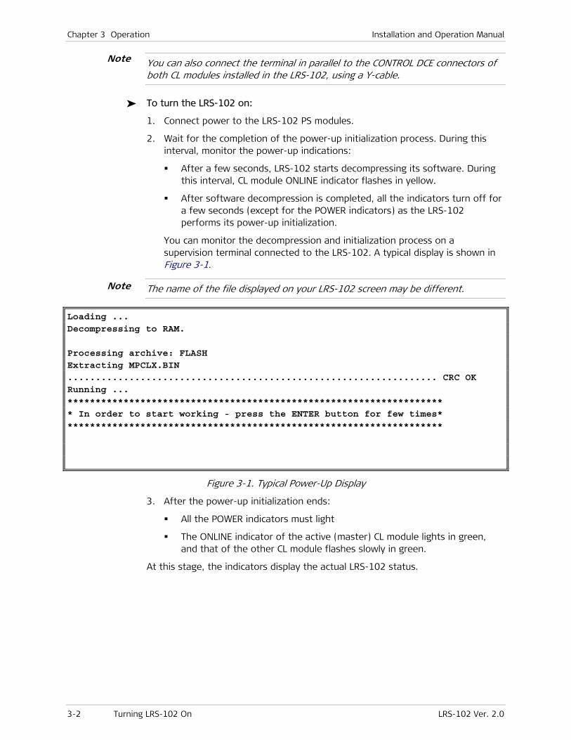
Chapter 3 Operation Installation and Operation Manual
3-2 Turning LRS-102 On LRS-102 Ver. 2.0
You can also connect the terminal in parallel to the CONTROL DCE connectors of both CL modules installed in the LRS-102, using a Y-cable.
To turn the LRS-102 on:
1. Connect power to the LRS-102 PS modules.
2. Wait for the completion of the power-up initialization process. During this interval, monitor the power-up indications:
After a few seconds, LRS-102 starts decompressing its software. During this interval, CL module ONLINE indicator flashes in yellow.
After software decompression is completed, all the indicators turn off for a few seconds (except for the POWER indicators) as the LRS-102 performs its power-up initialization.
You can monitor the decompression and initialization process on a supervision terminal connected to the LRS-102. A typical display is shown in Figure 3-1.
The name of the file displayed on your LRS-102 screen may be different.
Loading ... Decompressing to RAM. Processing archive: FLASH Extracting MPCLX.BIN .................................................................. CRC OK Running ... ******************************************************************* * In order to start working - press the ENTER button for few times* *******************************************************************
Figure 3-1. Typical Power-Up Display
3. After the power-up initialization ends:
All the POWER indicators must light
The ONLINE indicator of the active (master) CL module lights in green, and that of the other CL module flashes slowly in green.
At this stage, the indicators display the actual LRS-102 status.
Note
Note
Installation and Operation Manual Chapter 3 Operation
LRS-102 Ver. 2.0 Indications 3-3
3.2 Indications
The indications provided during normal operation are described below.
For a complete description of LRS-102 indicator functions, refer to Chapter 2.
System Indications
1. As long as the LRS-102 is powered, all its POWER indicators light steadily.
2. The ON LINE indicator of one of the CL modules must light steadily.
3. The front panel TEST indicator must be off, unless a test has been activated on the LRS-102 (in this case, the ON LINE indicator of the master CL module also lights in yellow).
4. The front panel ALARM indicators, and the CL ALM indicators must be off. However, they may flash or light, as long as one or more of the LRS-102 port are not connected to operational equipment.
CONTROL ETH Interface Status Indications
If an LRS-102 CONTROL ETH port is not yet connected to an active LAN, the corresponding LINK and ACT indicators are off.
After connecting the CONTROL ETH port to an active LAN, the corresponding LINK indicator must light. The ACT indicator of the port will flash, or appear to light steadily, in accordance with the traffic.
CLS.1 CLOCK Interface Status Indications
The ON indicator lights when the corresponding station clock interface is enabled. When the CLOCK connector is connected to an operational clock source, the LOS indicator of the corresponding station clock interface must be off: it will turn on if the clock signal is missing.
Note
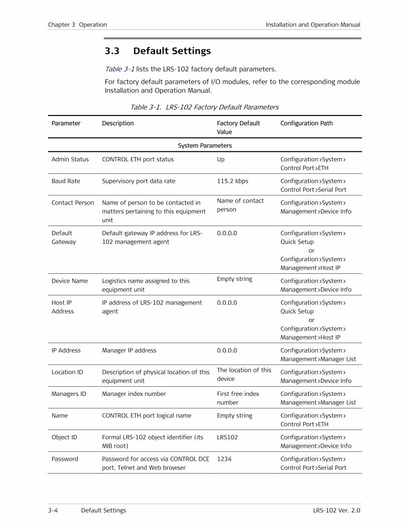
Chapter 3 Operation Installation and Operation Manual
3-4 Default Settings LRS-102 Ver. 2.0
3.3 Default Settings
Table 3-1 lists the LRS-102 factory default parameters.
For factory default parameters of I/O modules, refer to the corresponding module Installation and Operation Manual.
Table 3-1. LRS-102 Factory Default Parameters
Parameter Description Factory Default
Value
Configuration Path
System Parameters
Admin Status CONTROL ETH port status Up Configuration>System>
Control Port>ETH
Baud Rate Supervisory port data rate 115.2 kbps Configuration>System>
Control Port>Serial Port
Contact Person Name of person to be contacted in
matters pertaining to this equipment
unit
Name of contact
person Configuration>System>
Management>Device Info
Default
Gateway
Default gateway IP address for LRS-
102 management agent
0.0.0.0 Configuration>System>
Quick Setup
or
Configuration>System>
Management>Host IP
Device Name Logistics name assigned to this
equipment unit
Empty string Configuration>System>
Management>Device Info
Host IP
Address
IP address of LRS-102 management
agent
0.0.0.0 Configuration>System>
Quick Setup
or
Configuration>System>
Management>Host IP
IP Address Manager IP address 0.0.0.0 Configuration>System>
Management>Manager List
Location ID Description of physical location of this
equipment unit
The location of this
device Configuration>System>
Management>Device Info
Managers ID Manager index number First free index
number
Configuration>System>
Management>Manager List
Name CONTROL ETH port logical name Empty string Configuration>System>
Control Port>ETH
Object ID Formal LRS-102 object identifier (its
MIB root)
LRS102 Configuration>System>
Management>Device Info
Password Password for access via CONTROL DCE
port, Telnet and Web browser
1234 Configuration>System>
Control Port>Serial Port
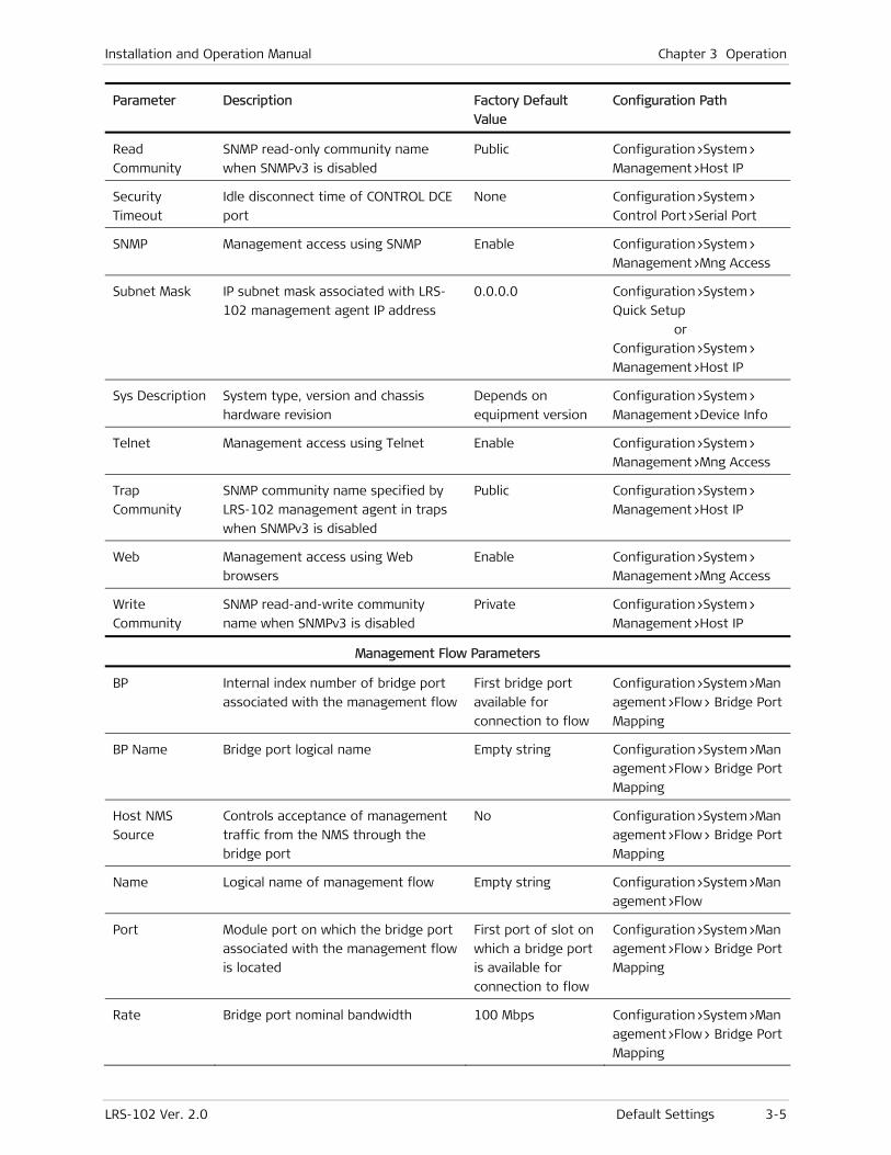
Installation and Operation Manual Chapter 3 Operation
LRS-102 Ver. 2.0 Default Settings 3-5
Parameter Description Factory Default
Value
Configuration Path
Read
Community
SNMP read-only community name
when SNMPv3 is disabled
Public Configuration>System>
Management>Host IP
Security
Timeout
Idle disconnect time of CONTROL DCE
port
None Configuration>System>
Control Port>Serial Port
SNMP Management access using SNMP Enable Configuration>System>
Management>Mng Access
Subnet Mask IP subnet mask associated with LRS-
102 management agent IP address
0.0.0.0 Configuration>System>
Quick Setup
or
Configuration>System>
Management>Host IP
Sys Description System type, version and chassis
hardware revision
Depends on
equipment version
Configuration>System>
Management>Device Info
Telnet Management access using Telnet Enable Configuration>System>
Management>Mng Access
Trap
Community
SNMP community name specified by
LRS-102 management agent in traps
when SNMPv3 is disabled
Public Configuration>System>
Management>Host IP
Web Management access using Web
browsers
Enable Configuration>System>
Management>Mng Access
Write
Community
SNMP read-and-write community
name when SNMPv3 is disabled
Private Configuration>System>
Management>Host IP
Management Flow Parameters
BP Internal index number of bridge port
associated with the management flow
First bridge port
available for
connection to flow
Configuration>System>Man
agement>Flow> Bridge Port
Mapping
BP Name Bridge port logical name Empty string Configuration>System>Man
agement>Flow> Bridge Port
Mapping
Host NMS
Source
Controls acceptance of management
traffic from the NMS through the
bridge port
No Configuration>System>Man
agement>Flow> Bridge Port
Mapping
Name Logical name of management flow Empty string Configuration>System>Man
agement>Flow
Port Module port on which the bridge port
associated with the management flow
is located
First port of slot on
which a bridge port
is available for
connection to flow
Configuration>System>Man
agement>Flow> Bridge Port
Mapping
Rate Bridge port nominal bandwidth 100 Mbps Configuration>System>Man
agement>Flow> Bridge Port
Mapping
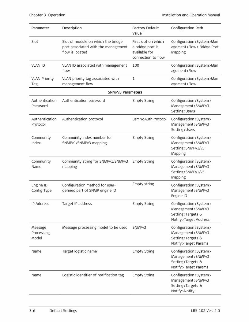
Chapter 3 Operation Installation and Operation Manual
3-6 Default Settings LRS-102 Ver. 2.0
Parameter Description Factory Default
Value
Configuration Path
Slot Slot of module on which the bridge
port associated with the management
flow is located
First slot on which
a bridge port is
available for
connection to flow
Configuration>System>Man
agement>Flow> Bridge Port
Mapping
VLAN ID VLAN ID associated with management
flow
100 Configuration>System>Man
agement>Flow
VLAN Priority
Tag
VLAN priority tag associated with
management flow
1 Configuration>System>Man
agement>Flow
SNMPv3 Parameters
Authentication
Password
Authentication password Empty String Configuration>System>
Management>SNMPv3
Setting>Users
Authentication
Protocol
Authentication protocol usmNoAuthProtocol Configuration>System>
Management>SNMPv3
Setting>Users
Community
Index
Community index number for
SNMPv1/SNMPv3 mapping
Empty String Configuration>System>
Management>SNMPv3
Setting>SNMPv1/v3
Mapping
Community
Name
Community string for SNMPv1/SNMPv3
mapping
Empty String Configuration>System>
Management>SNMPv3
Setting>SNMPv1/v3
Mapping
Engine ID
Config Type
Configuration method for user-
defined part of SNMP engine ID
Empty string Configuration>System>
Management>SNMPv3
Engine ID
IP Address Target IP address Empty String Configuration>System>
Management>SNMPv3
Setting>Targets &
Notify>Target Address
Message
Processing
Model
Message processing model to be used SNMPv3 Configuration>System>
Management>SNMPv3
Setting>Targets &
Notify>Target Params
Name Target logistic name Empty String Configuration>System>
Management>SNMPv3
Setting>Targets &
Notify>Target Params
Name Logistic identifier of notification tag Empty String Configuration>System>
Management>SNMPv3
Setting>Targets &
Notify>Notify
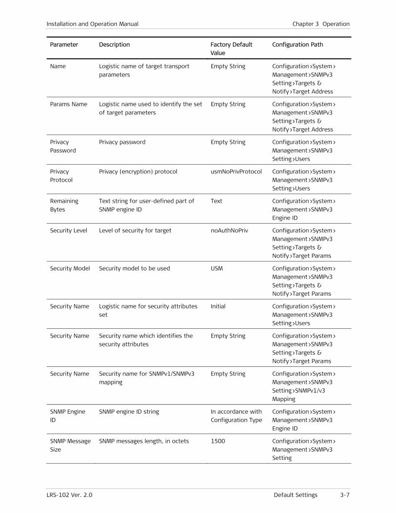
Installation and Operation Manual Chapter 3 Operation
LRS-102 Ver. 2.0 Default Settings 3-7
Parameter Description Factory Default
Value
Configuration Path
Name Logistic name of target transport
parameters
Empty String Configuration>System>
Management>SNMPv3
Setting>Targets &
Notify>Target Address
Params Name Logistic name used to identify the set
of target parameters
Empty String Configuration>System>
Management>SNMPv3
Setting>Targets &
Notify>Target Address
Privacy
Password
Privacy password Empty String Configuration>System>
Management>SNMPv3
Setting>Users
Privacy
Protocol
Privacy (encryption) protocol usmNoPrivProtocol Configuration>System>
Management>SNMPv3
Setting>Users
Remaining
Bytes
Text string for user-defined part of
SNMP engine ID
Text Configuration>System>
Management>SNMPv3
Engine ID
Security Level Level of security for target noAuthNoPriv Configuration>System>
Management>SNMPv3
Setting>Targets &
Notify>Target Params
Security Model Security model to be used USM Configuration>System>
Management>SNMPv3
Setting>Targets &
Notify>Target Params
Security Name Logistic name for security attributes
set
Initial Configuration>System>
Management>SNMPv3
Setting>Users
Security Name Security name which identifies the
security attributes
Empty String Configuration>System>
Management>SNMPv3
Setting>Targets &
Notify>Target Params
Security Name Security name for SNMPv1/SNMPv3
mapping
Empty String Configuration>System>
Management>SNMPv3
Setting>SNMPv1/v3
Mapping
SNMP Engine
ID
SNMP engine ID string In accordance with
Configuration Type
Configuration>System>
Management>SNMPv3
Engine ID
SNMP Message
Size
SNMP messages length, in octets 1500 Configuration>System>
Management>SNMPv3
Setting
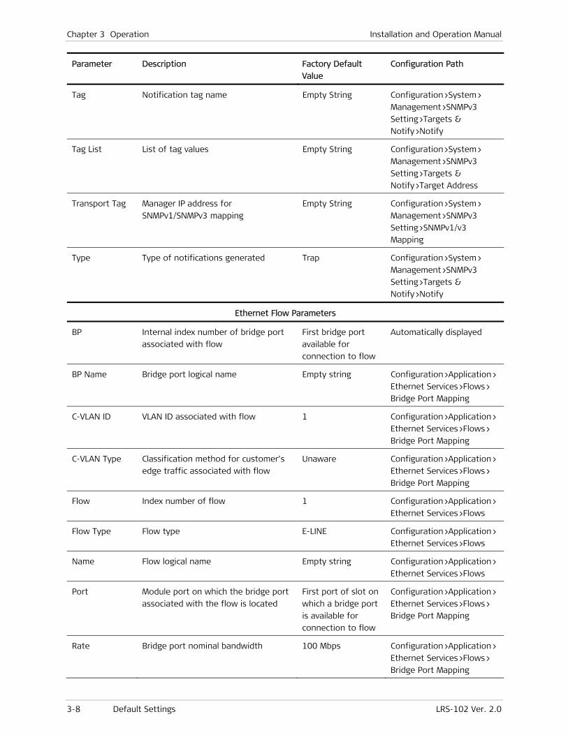
Chapter 3 Operation Installation and Operation Manual
3-8 Default Settings LRS-102 Ver. 2.0
Parameter Description Factory Default
Value
Configuration Path
Tag Notification tag name Empty String Configuration>System>
Management>SNMPv3
Setting>Targets &
Notify>Notify
Tag List List of tag values Empty String Configuration>System>
Management>SNMPv3
Setting>Targets &
Notify>Target Address
Transport Tag Manager IP address for
SNMPv1/SNMPv3 mapping
Empty String Configuration>System>
Management>SNMPv3
Setting>SNMPv1/v3
Mapping
Type Type of notifications generated Trap Configuration>System>
Management>SNMPv3
Setting>Targets &
Notify>Notify
Ethernet Flow Parameters
BP Internal index number of bridge port
associated with flow
First bridge port
available for
connection to flow
Automatically displayed
BP Name Bridge port logical name Empty string Configuration>Application>
Ethernet Services>Flows>
Bridge Port Mapping
C-VLAN ID VLAN ID associated with flow 1 Configuration>Application>
Ethernet Services>Flows>
Bridge Port Mapping
C-VLAN Type Classification method for customer’s
edge traffic associated with flow
Unaware Configuration>Application>
Ethernet Services>Flows>
Bridge Port Mapping
Flow Index number of flow 1 Configuration>Application>
Ethernet Services>Flows
Flow Type Flow type E-LINE Configuration>Application>
Ethernet Services>Flows
Name Flow logical name Empty string Configuration>Application>
Ethernet Services>Flows
Port Module port on which the bridge port
associated with the flow is located
First port of slot on
which a bridge port
is available for
connection to flow
Configuration>Application>
Ethernet Services>Flows>
Bridge Port Mapping
Rate Bridge port nominal bandwidth 100 Mbps Configuration>Application>
Ethernet Services>Flows>
Bridge Port Mapping

Installation and Operation Manual Chapter 3 Operation
LRS-102 Ver. 2.0 Configuration and Management Alternatives 3-9
Parameter Description Factory Default
Value
Configuration Path
Slot Slot number of module on which the
bridge port associated with the flow
is located
First slot on which
a bridge port is
available for
connection to flow
Configuration>Application>
Ethernet Services>Flows>
Bridge Port Mapping
SP-VLAN Service provider’s edge VLAN ID
associated with flow
0 Configuration>Application>
Ethernet Services>Flows>
Bridge Port Mapping
3.4 Configuration and Management Alternatives
The LRS-102 configuration activities can be performed by means of the following:
• Supervision terminal
• Telnet
• Web browser, using the ConfiguRAD utility
• SNMP-based network management systems, e.g., the RADview network management system (refer to the RADview User's Manual for instructions).
LRS-102 also supports SNMPv3, which provides authentication and privacy capabilities that replace the basic SNMP community-based authentication available under SNMPv1.
The user can select whether to enable management by means of Telnet, SNMP, and/or Web browsers: only the supervision terminal is always able to configure the LRS-102.
The capabilities of all the options listed above are similar, except that before using Telnet, Web browsers, and/or network management stations, it is necessary to perform preliminary configuration using the supervision terminal.
The LRS-102 supports simultaneous management sessions: it is user’s responsibility to prevent access conflicts and configuration errors that may occur when multiple users simultaneously access the same equipment.
Access Levels for Configuration and Management
LRS-102 supports three access levels, which determine the functions the users can perform using supervisory terminals, Telnet hosts, and Web browsers.
When SNMPv3 security features are enabled, the term user refers to an SNMP management station using part, or all of the SNMPv3 security features, and the users’ authorizations are determined by configuring the parameters related to the view-based security model (VACM) aspect of SNMPv3. Refer to Section 0 and Chapter 4 for details.
Note
Note
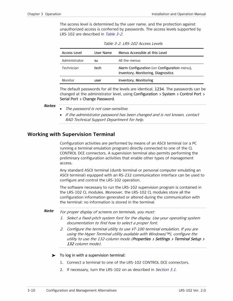
Chapter 3 Operation Installation and Operation Manual
3-10 Configuration and Management Alternatives LRS-102 Ver. 2.0
The access level is determined by the user name, and the protection against unauthorized access is conferred by passwords. The access levels supported by LRS-102 are described in Table 3-2.
Table 3-2. LRS-102 Access Levels
Access Level User Name Menus Accessible at this Level
Administrator su All the menus
Technician tech Alarm Configuration (on Configuration menu),
Inventory, Monitoring, Diagnostics
Monitor user Inventory, Monitoring
The default passwords for all the levels are identical, 1234. The passwords can be changed at the administrator level, using Configuration > System > Control Port > Serial Port > Change Password. P
• The password is not case-sensitive.
• If the administrator password has been changed and is not known, contact RAD Technical Support Department for help.
Working with Supervision Terminal
Configuration activities are performed by means of an ASCII terminal (or a PC running a terminal emulation program) directly connected to one of the CL CONTROL DCE connectors. A supervision terminal also permits performing the preliminary configuration activities that enable other types of management access.
Any standard ASCII terminal (dumb terminal or personal computer emulating an ASCII terminal) equipped with an RS-232 communication interface can be used to configure and control the LRS-102 operation.
The software necessary to run the LRS-102 supervision program is contained in the LRS-102 CL modules. Moreover, the LRS-102 CL modules store all the configuration information generated or altered during the communication with the terminal: no information is stored in the terminal.
For proper display of screens on terminals, you must:
1. Select a fixed-pitch system font for the display. Use your operating system documentation to find how to select a proper font.
2. Configure the terminal utility to use VT-100 terminal emulation. If you are using the Hyper Terminal utility available with Windows(™), configure the utility to use the 132-column mode (Properties > Settings > Terminal Setup > 132 column mode).
To log in with a supervision terminal:
1. Connect a terminal to one of the LRS-102 CONTROL DCE connectors.
2. If necessary, turn the LRS-102 on as described in Section 3.1.
Note
Notes
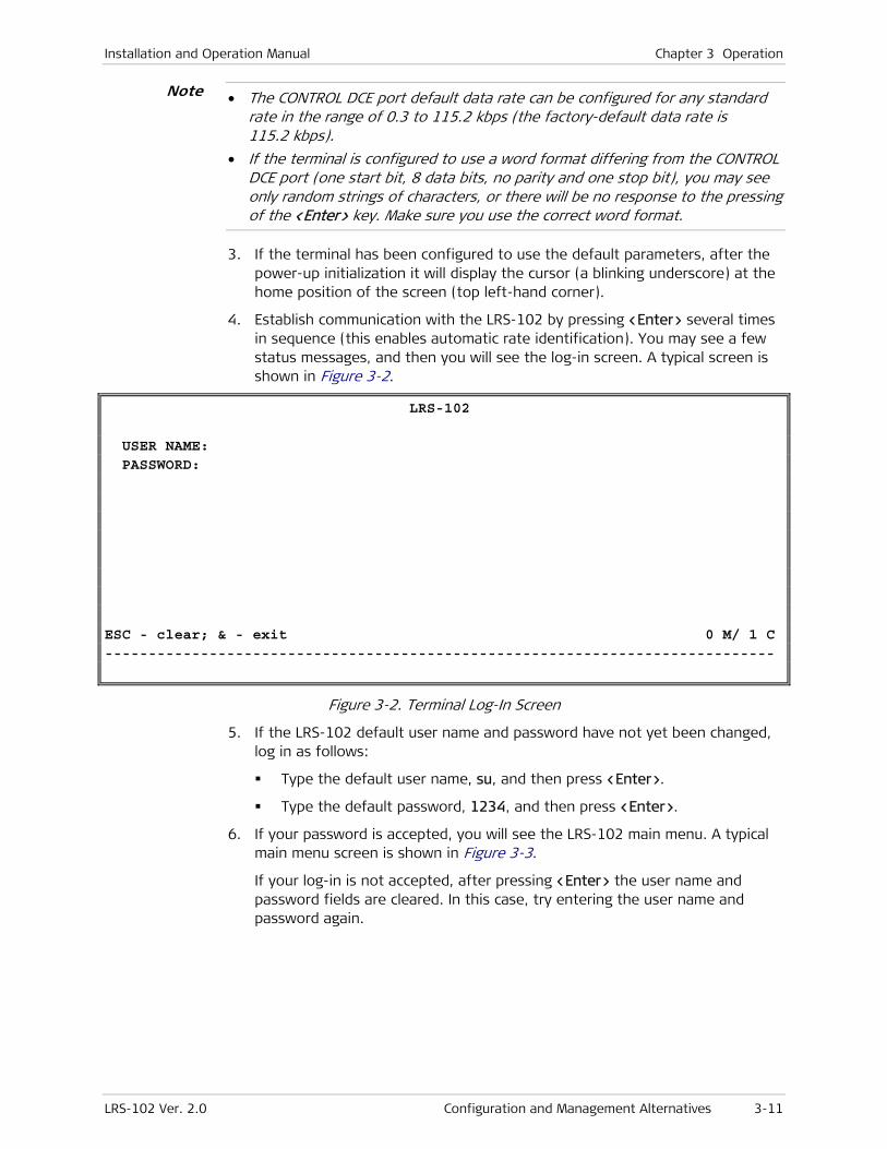
Installation and Operation Manual Chapter 3 Operation
LRS-102 Ver. 2.0 Configuration and Management Alternatives 3-11
• The CONTROL DCE port default data rate can be configured for any standard rate in the range of 0.3 to 115.2 kbps (the factory-default data rate is 115.2 kbps).
• If the terminal is configured to use a word format differing from the CONTROL DCE port (one start bit, 8 data bits, no parity and one stop bit), you may see only random strings of characters, or there will be no response to the pressing of the <Enter> key. Make sure you use the correct word format.
3. If the terminal has been configured to use the default parameters, after the power-up initialization it will display the cursor (a blinking underscore) at the home position of the screen (top left-hand corner).
4. Establish communication with the LRS-102 by pressing <Enter> several times in sequence (this enables automatic rate identification). You may see a few status messages, and then you will see the log-in screen. A typical screen is shown in Figure 3-2.
LRS-102 USER NAME: PASSWORD: ESC - clear; & - exit 0 M/ 1 C -----------------------------------------------------------------------------
Figure 3-2. Terminal Log-In Screen
5. If the LRS-102 default user name and password have not yet been changed, log in as follows:
Type the default user name, su, and then press <Enter>.
Type the default password, 1234, and then press <Enter>.
6. If your password is accepted, you will see the LRS-102 main menu. A typical main menu screen is shown in Figure 3-3.
If your log-in is not accepted, after pressing <Enter> the user name and password fields are cleared. In this case, try entering the user name and password again.
Note
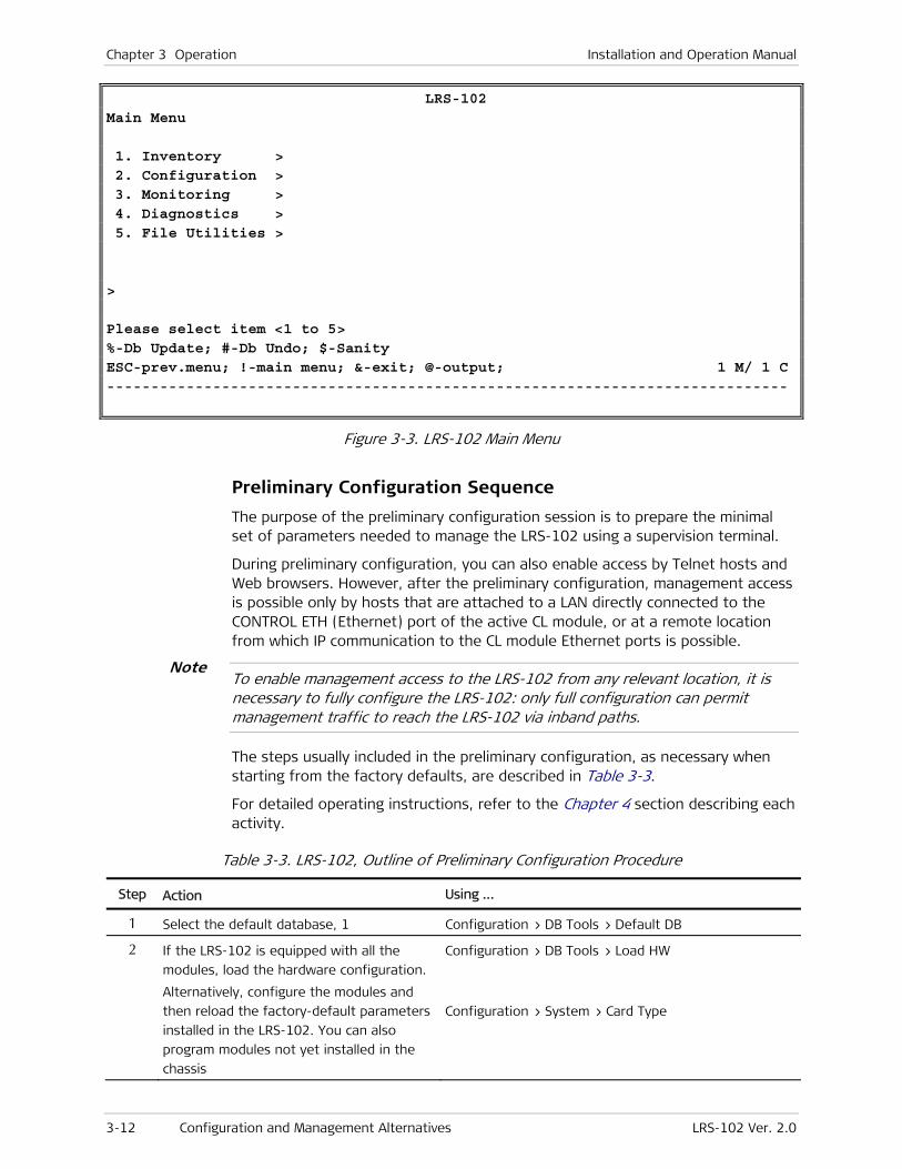
Chapter 3 Operation Installation and Operation Manual
3-12 Configuration and Management Alternatives LRS-102 Ver. 2.0
LRS-102 Main Menu 1. Inventory > 2. Configuration > 3. Monitoring > 4. Diagnostics > 5. File Utilities > > Please select item <1 to 5> %-Db Update; #-Db Undo; $-Sanity ESC-prev.menu; !-main menu; &-exit; @-output; 1 M/ 1 C -----------------------------------------------------------------------------
Figure 3-3. LRS-102 Main Menu
Preliminary Configuration Sequence
The purpose of the preliminary configuration session is to prepare the minimal set of parameters needed to manage the LRS-102 using a supervision terminal.
During preliminary configuration, you can also enable access by Telnet hosts and Web browsers. However, after the preliminary configuration, management access is possible only by hosts that are attached to a LAN directly connected to the CONTROL ETH (Ethernet) port of the active CL module, or at a remote location from which IP communication to the CL module Ethernet ports is possible.
To enable management access to the LRS-102 from any relevant location, it is necessary to fully configure the LRS-102: only full configuration can permit management traffic to reach the LRS-102 via inband paths.
The steps usually included in the preliminary configuration, as necessary when starting from the factory defaults, are described in Table 3-3.
For detailed operating instructions, refer to the Chapter 4 section describing each activity.
Table 3-3. LRS-102, Outline of Preliminary Configuration Procedure
Step Action Using …
1 Select the default database, 1 Configuration > DB Tools > Default DB
2 If the LRS-102 is equipped with all the
modules, load the hardware configuration.
Alternatively, configure the modules and
then reload the factory-default parameters
installed in the LRS-102. You can also
program modules not yet installed in the
chassis
Configuration > DB Tools > Load HW
Configuration > System > Card Type
Note
Installation and Operation Manual Chapter 3 Operation
LRS-102 Ver. 2.0 Configuration and Management Alternatives 3-13
Step Action Using …
3 Configure CONTROL DCE port parameters Configuration > System > Control Port > Serial Port
4 Configure CONTROL ETH port parameters Configuration > System > Control Port > ETH
5 Configure the LRS-102 management agent Configuration > System > Management > Host IP
6 Configure LRS-102 management access Configuration > System > Management > Mng Access
7 Configure specific managers (optional) Configuration > System > Management > Manager List
8 Set LRS-102 real-time clock (optional) Configuration > System > Date & Time
9 Save the configured information in the
selected database
Configuration > DB Tools > Update DB
• All the following menus are reached after opening the Configuration menu.
• During the configuration procedure, save the changed values, but update the database only after completing the configuration activities.
Select the default database:
1. Open the DB Tools menu.
2. Select Default DB.
3. Select the default database number, 1.
Initialize the LRS-102:
1. Select Load HW on the DB Tools menu.
2. Select Update DB on the DB Tools menu to activate the default configuration for all the hardware installed in the LRS-102. When prompted to confirm, type Y.
The new database takes effect immediately. You will see the message Configuration File Update is in Process while the database is saved in the CL module flash memory.
Reload the factory defaults:
1. Select Factory Default on the Configuration > System menu.
To program modules not yet installed in the LRS-102 chassis:
1. Select Card Type on the System menu.
2. Move the cursor to the desired slot.
3. The selections supported for each slot are automatically displayed under the slots table. Type the item number corresponding to the desired selection and then press <Enter>.
4. Repeat Steps 2, 3 for each slot.
Configure the serial port parameters:
1. Open Control Port on the System menu.
Note
Chapter 3 Operation Installation and Operation Manual
3-14 Configuration and Management Alternatives LRS-102 Ver. 2.0
2. Open Serial Port on the Control Port submenu.
3. Select the desired value for Speed (recommended value: 115200).
Configure the LRS-102 management agent parameters:
1. Open Host IP on the System > Management menu.
2. Configure the prescribed values for the following parameters:
IP Address. Enter the IP address of the LRS-102 management agent, using the dotted-quad format (four groups of digits in the range of 0 through 255, separated by periods).
IP Mask. Enter the IP subnet mask of the LRS-102 management agent. Make sure to select a subnet mask compatible with the selected IP address, and whose binary representation consists of consecutive “ones”, followed by the desired number of consecutive “zeroes”.
Default Gateway. Specify the IP address (usually an IP router port) to which the LRS-102 management agent will send packets when the destination IP address is not within the subnet specified in the Mask field. Type the desired IP address, using the dotted-quad format. Make sure that the IP address is within the subnet of the host IP address. The default value, 0.0.0.0, means that no default gateway is defined.
Communities: to configure SNMP management when SNMPv3 is Disabled, enter the prescribed Read, Write, and Trap community names, or leave the defaults unchanged.
When SNMPv3 is Enabled¸ the community fields are not displayed.
The community names are case-sensitive.
Configure the Ethernet port parameters:
1. Open Control Port on the System menu.
2. Open ETH on the Control Port submenu.
3. For each CL module, select UP for Admin Status. You may also assign a user name (up to 10 characters) to each port.
4. At this stage, you may leave None for Routing Protocol.
Configure management access options:
1. Open Management on the System menu.
2. Open Mng Access on the Management submenu.
3. Select Enable or Disable, as prescribed, for Telnet, Web, and/or SNMP.
Configure specific management stations:
1. Open Management on the System menu.
2. Open Manager List on the Management submenu.
3. Type a (add) and then press <Enter> to start the configuration of a new management station.
Note

Installation and Operation Manual Chapter 3 Operation
LRS-102 Ver. 2.0 Configuration and Management Alternatives 3-15
4. Select the prescribed values for each parameter.
5. After ending the configuration and saving the changes, the Manager List screen is updated to include the new station. To display the Manager List again, press ESC.
6. Repeat the process until all the desired management stations have been defined.
Set the LRS-102 real-time clock:
1. Open the System menu.
2. Select Date & Time on the System menu.
3. Open Set Date Format screen, and select the desired date format.
dd stands for day, mm for month and yyyy for year.
4. When done, save and then set each component of the time-of-day and date. To change, select the desired item and then type the desired value. Confirm each change by pressing <Enter>.
• Time must be entered in the 24-hour format.
• It is recommended to set the time about one minute beyond the desired time, and then press <Enter> at the correct instant.
Save the changes to the default database:
1. On the DB Tools menu, select Update DB to save and activate the new configuration.
You may also use the % shortcut.
Configuring LRS-102 via Supervisory Terminal
LRS-102 operating mode, and all of its functions, are controlled by a set of configuration parameters organized as a database, which is stored in the flash memory on the LRS-102 CL module. The parameters in the database are selected by the user in accordance with the requirements of each specific application.
To provide a starting point for the user, RAD provide a fixed set of factory-default parameters. The factory defaults are not modified by user configuration activities, and therefore these factory-defaults can be reloaded whenever needed.
The preparation of the desired set of configuration parameters is made in accordance with a set of rules, which together form the LRS-102 supervision utility, or user interface. The supervision utility is used to communicate with the central control subsystem of the LRS-102 located in the CL modules, using a supervision terminal connected to the control port of the CL module. The same user interface can also be used by Telnet hosts.
An alternative way to change the configuration parameters is by means of a Web browser.
Note
Notes

Chapter 3 Operation Installation and Operation Manual
3-16 Configuration and Management Alternatives LRS-102 Ver. 2.0
Preparing New Configuration Parameters
Normally, only one database is needed to store the configuration parameters; when necessary, one or more additional databases with alternative configurations may also be prepared and stored in the LRS-102 flash memory. LRS-102 databases are assigned index numbers in the range of 1 to 10.
At any time, one of the stored databases (the database assigned index number 1) serves as the active (online) database, and it is also the database automatically loaded upon power-up. Since the active database is stored in flash memory, the latest configuration parameters are always available upon power-up.
During the preparation of configuration parameters, the central control subsystem of the LRS-102 dedicates a section of its RAM, called editing buffer, to this process. The editing buffer contains a copy of a user-selected database (any of the databases stored by the LRS-102, including the currently-active database), and only this copy is modified by the commands entered by the user. Therefore, you can make configuration changes and cancel them as required without affecting the traffic flow through the LRS-102.
Any changes to configuration parameters remain temporary, and thus are lost if LRS-102 is powered off or reset, until they are saved to one of the databases in LRS-102 flash memory. You can decide in which database to save the changes: this also determines whether the changes take effect immediately or not.
Two options are available:
• Normally, changes are saved to the active, or online, database. In this case, the changes are also automatically activated, that is, LRS-102 starts using the new parameters. As mentioned above, the number of the active database is always 1, irrespective of the number of the database loaded into the edit buffer as a basis for changes.
• Alternatively, you can specify the number of another database, using the Update DB command, in which to store the edit buffer contents. If the database whose index is specified in the Update DB command is not yet stored in the flash memory, a database with this index number is created and the edit buffer contents are stored in it.
The storage space used by databases increases after each change. Sometimes, the remaining storage space is not sufficient to save the updated database, and you will see Save of Configuration File Failed. In this case, it is necessary to delete unused databases.
Note that alternative databases may be assigned any desired number, except 1, because 1 is reserved for the active database.
When preparing alternative databases, it is convenient to change the default database, that is, the database which is updated when you use the shortcut % - DB Update:
• If you do not select a specific default database, the shortcut updates the active database (database 1).
• If you specify another database stored in the flash memory as default, the shortcut updates the default database. In this case, after preparing the alternative database, it is recommended to return the default to database 1.
Note
Installation and Operation Manual Chapter 3 Operation
LRS-102 Ver. 2.0 Configuration and Management Alternatives 3-17
Validity Checks
The LRS-102 control subsystem automatically checks the validity of each new subset of parameters selected by the user as soon as an attempt to save them is made, alerts the user to potential conflicts, and rejects erroneous selections.
The “sanity check” is performed on the configuration parameters stored in the editing buffer.
This function provides messages which help identify incomplete configuration, unconnected timeslots, conflicting parameters, inconsistent selection of related parameter values, etc., so that the parameters can be corrected before proceeding.
Only after all the validity and sanity checks are successfully passed, can the user save the new (or modified) set of configuration parameters as a database (this is made by means of the Update DB command). If the new set is saved under the number of the active configuration database, the LRS-102 system will start operating in accordance with the new configuration.
Since the last validated sets of configuration parameters are stored in flash memory, LRS-102 configuration is not affected when the power is turned off. However, any changes not yet saved are lost if the LRS-102 is reset or powered down.
LRS-102 Power-up Process
Upon turn-on, the LRS-102 central control subsystem always loads database 1, and checks the validity of the configuration data. If everything is OK, it loads the data into the working memory and reconfigures the system accordingly. Therefore, the LRS-102 is ready for operation in accordance with the last configuration stored in database 1 immediately after power is applied.
If necessary, after power-up another database can be loaded by means of the Load DB command, and then activated by means of the shortcut % - DB Update. This database will be assigned index number 1 (that is, will become database 1).
If the configuration data is not valid, the database will not be activated; instead, a database with factory-default values will be activated. This database will be assigned index number 1 (that is, will become database 1).
After the operating parameters have been loaded, a process called configuration set-up, the LRS-102 no longer requires operator attendance.
Organization of Terminal Screens
The LRS-102 is managed via a simple, menu-driven utility that uses a basic terminal user interface. Figure 3-4 shows a typical utility screen with most types of terminal user interface items.
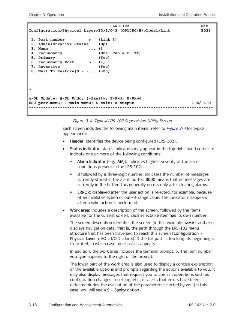
Chapter 3 Operation Installation and Operation Manual
3-18 Configuration and Management Alternatives LRS-102 Ver. 2.0
LRS-102 Min Configuration>Physical Layer>IO>I/O-3 (OP108C/B)>Local>Link B023 1. Port number > (Link 3) 2. Administrative Status (Up) 3. Name ... () 4. Redundancy (Dual Cable P. TX) 5. Primary (Yes) 6. Redundancy Port > (-) 7. Revertive (Yes) 8. Wait To Restore[0 - 9... (300) > %-Db Update; #-Db Undo; $-Sanity; F-Fwd; B-Bkwd ESC-prev.menu; !-main menu; &-exit; @-output 1 M/ 1 C -----------------------------------------------------------------------------
Figure 3-4. Typical LRS-102 Supervision Utility Screen
Each screen includes the following main items (refer to Figure 3-4 for typical appearance):
• Header: identifies the device being configured (LRS-102).
• Status indicator: status indicators may appear in the top right-hand corner to indicate one or more of the following conditions:
Alarm Indicator (e.g., MAJ): indicates highest severity of the alarm conditions present in the LRS-102.
B followed by a three-digit number: indicates the number of messages currently stored in the alarm buffer. B000 means that no messages are currently in the buffer: this generally occurs only after clearing alarms.
ERROR: displayed after the user action is rejected, for example, because of an invalid selection or out-of-range value. The indicator disappears after a valid action is performed.
• Work area: includes a description of the screen, followed by the items available for the current screen. Each selectable item has its own number.
The screen description identifies the screen (in this example: Link), and also displays navigation data, that is, the path through the LRS-102 menu structure that has been traversed to reach this screen (Configuration > Physical Layer > I/O > I/O 1 > Link). If the full path is too long, its beginning is truncated, in which case an ellipsis … appears.
In addition, the work area includes the terminal prompt, >. The item number you type appears to the right of the prompt.
The lower part of the work area is also used to display a concise explanation of the available options and prompts regarding the actions available to you. It may also display messages that request you to confirm operations such as configuration changes, resetting, etc., or alerts that errors have been detected during the evaluation of the parameters selected by you (in this case, you will see a $ – Sanity option).

Installation and Operation Manual Chapter 3 Operation
LRS-102 Ver. 2.0 Configuration and Management Alternatives 3-19
• % – DB Update, # – DB Undo : after you make a configuration change, you must either save it in one of the databases, or undo (cancel) it.
When you press the % hotkey, the changes are saved to the default database, which is usually database 1, unless you selected a different default database.
Changes that have been saved to a database using the Update DB command will take effect only after that database is selected as active database.
• Save: after you make configuration changes on certain screens, you must temporarily save the changes in the edit buffer, or undo (cancel). Changes that have been saved can take effect only after the current database is updated.
The indication that changes have been made is provided by the appearance of the S – Save item in the bottom line of the configuration screen. After saving, the S – Save item disappears.
• Bottom line: displays the keys used for navigation.
ESC returns to the previous screen (not relevant for main menu)
! returns directly to the main menu (not relevant for main menu)
& – ends the utility and displays the log-in screen again.
@ – increases the area dedicated to the on line display.
? – displays additional help specific to the current screen.
In addition, the number of management connections (C) and the number of managers (M) currently connected to the LRS-102 is shown at the lower right-hand corner (in Figure 3-4, this is 1 manager via one management connection). The managers’ number indicates the total number of management sessions active at the instant the screen was displayed, irrespective of type (terminal, Telnet, SNMP or Web browser). If no user is logged in, the number of managers is 0.
• The last two rows are reserved for displaying the last two alarms, or user prompts.
It is normal to see at least a RESET OCCURRED event after power up. If not all of the LRS-102 ports are connected to operating equipment, you may also see alarms reporting loss of signals, etc.
General Supervision Terminal Operating Procedures
How to use the terminal to perform a desired activity:
• To select a menu item, type the corresponding line number and then press <Enter>. This will either …
… display a submenu or a parameter selection screen …
or …
… let you type the (free text) parameter value in the same row
or …
Note
Chapter 3 Operation Installation and Operation Manual
3-20 Configuration and Management Alternatives LRS-102 Ver. 2.0
… toggle the current value of the corresponding parameter (relevant to ENABLE/DISABLE or ON/OFF selections).
• The type of response to be expected after selecting a menu item is indicated as follows:
> Selecting that item will display a submenu or a parameter selection screen (see for example item 6 in Figure 3-4).
... Selecting that item will let you type the desired value in the same line (see for example item 1 in Figure 3-4).
Nothing When neither symbol is displayed, selecting that item will toggle the current selection, now shown in brackets (for example, this will change ENABLE to DISABLE or vice versa).
• When a menu does not fit on one screen (because it includes too many lines), it is displayed on two consecutive pages. In this case, you will see …(N) after the last line on the first page and …(P) before the first line on the second page:
While on the first page, press N to display the second page
While on the second page, press P to return to the first page.
• When a configuration screen is organized as a table, a special set of keys is used for navigation within the table (such screens always have a ? (help) option that displays these keys). The following keys may be used for navigation within tables:
Left Arrow (←) – move to the left Right arrow (→) – move to the right
Down Arrow (↓) –move down Up Arrow (↑) – move up
^D – scroll down ^U – scroll up
F – next B – previous
In addition, the following shortcuts are also available:
Tab – select the next cell that may be changed
M – switch to the menu mode
G followed by <row number>,<col number> – select a specific cell. For example, type G2,5 to select the fifth cell in the second row.
• The current value of a parameter is listed within parentheses ( ). To change a parameter value on a parameter selection screen:
Type the line number corresponding to the desired value, and then press <Enter>
To enter a value which requires free text entry, type in the desired string and then press <Enter>. Use backspace to erase the current string.
Note that whenever applicable, the allowed range of values of a parameter is listed within square brackets [ ].
• The entry is checked after pressing <Enter>, and it is accepted only if it is valid. If you make an error, for example, if you press a key not active on the
Installation and Operation Manual Chapter 3 Operation
LRS-102 Ver. 2.0 Configuration and Management Alternatives 3-21
current screen or select an invalid parameter value, an ERROR indicator appears in the upper right-hand corner. This indicator disappears as soon as you make a correct operation.
• When done with the current screen, press ESC to return to the previous screen, or type ! to return directly to the main menu.
Saving Changes to the Configuration Database
To save all the pending changes, type % (DB Update). You will be prompted to confirm: type y to continue or n to cancel.
After confirming, the new database takes effect immediately. You will see the message Configuration File Update is in Process while the database is saved in the CL module flash memory.
If you save the changes to the default database, the changes will be activated, that is, the operation mode of the LRS-102 changes in accordance with the new parameters values. In this case, press <Enter> several times in sequence to reestablish communication with the LRS-102.
• To undo (cancel) all the as-yet unsaved changes, type # – DB Undo and then confirm.
Any unsaved changes are lost when the LRS-102 is powered down.
Ending a Terminal Configuration Session
To end the current terminal session:
Type & and then press <Enter>.
In addition, LRS-102 will automatically terminate the current session after no activity is detected for a user-selected time-out interval (default – 3 minutes, can be increased to 10 minutes). The automatic session termination can however be disabled. The time-out option is selected using Configuration > System > Control Port > Serial Port > Security Timeout.
After a session is ended, it is necessary to enter again a valid user name and password to start a new session.
Menu Structure of Supervision Utility
Figure 3-5 shows the structure of the main menu.
Note
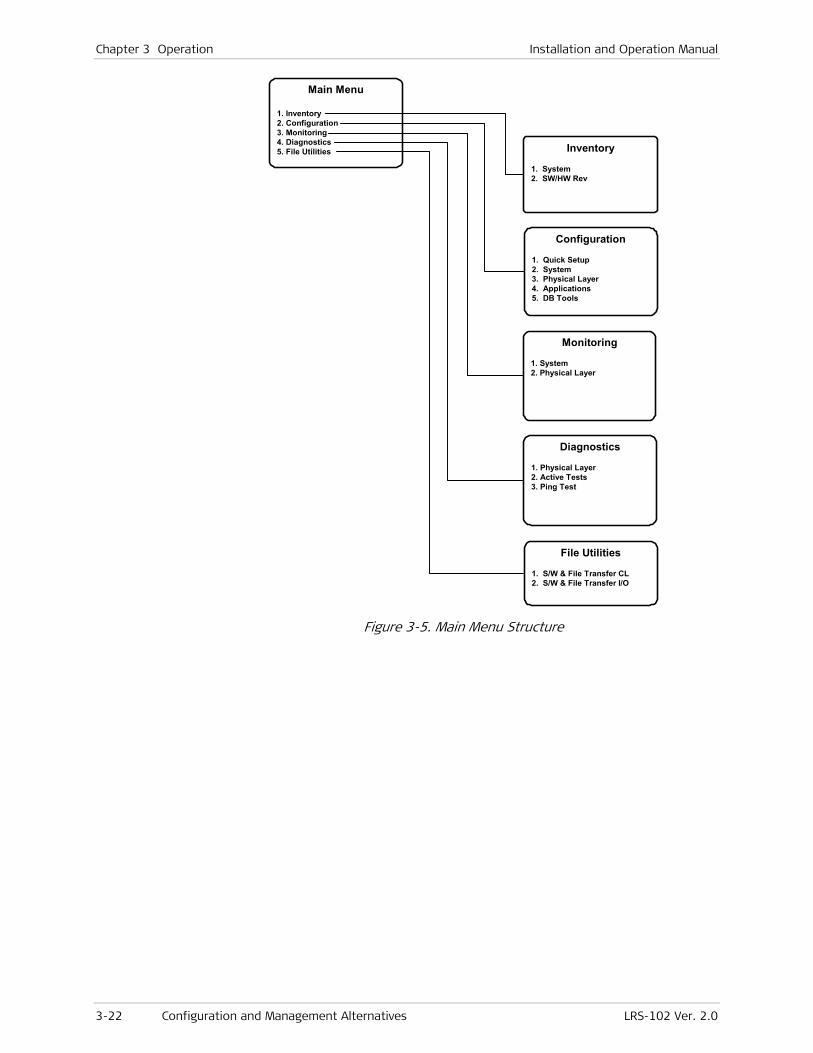
Chapter 3 Operation Installation and Operation Manual
3-22 Configuration and Management Alternatives LRS-102 Ver. 2.0
Main Menu
1. Inventory 2. Configuration 3. Monitoring 4. Diagnostics 5. File Utilities Inventory
1. System 2. SW/HW Rev
Configuration
1. Quick Setup 2. System 3. Physical Layer 4. Applications 5. DB Tools
Monitoring
1. System 2. Physical Layer
Diagnostics
1. Physical Layer 2. Active Tests 3. Ping Test
File Utilities
1. S/W & File Transfer CL 2. S/W & File Transfer I/O
Figure 3-5. Main Menu Structure

Installation and Operation Manual Chapter 3 Operation
LRS-102 Ver. 2.0 Configuration and Management Alternatives 3-23
The functions of the various main menu items are as follows:
Inventory Displays logistics information on the LRS-102. See Chapter 4 for details.
Configuration Configure LRS-102 operational parameters, and manage its database files. See Chapter 4 for details.
Monitoring Display LRS-102 alarms, events and status, and the performance monitoring statistics. See Chapter 6 for details.
Diagnostics Activate tests and loopbacks on the various ports, and check IP connectivity. See Chapter 6 for details.
File Utilities Use the file transfer utilities. See Chapter 4 for details.
Figure 3-6 through Figure 3-16 show the detailed menu structure of the supervision utility.
You may use these figures to find the screen used for any desired activity. For additional details, refer to the Chapter listed in the description of the main menu, where you will find a detailed view and a description of the functions and parameters available on each screen.
Inventory
1. System 2. SW/HW Rev
System
SW/HW Rev
Figure 3-6. Inventory Menu Structure
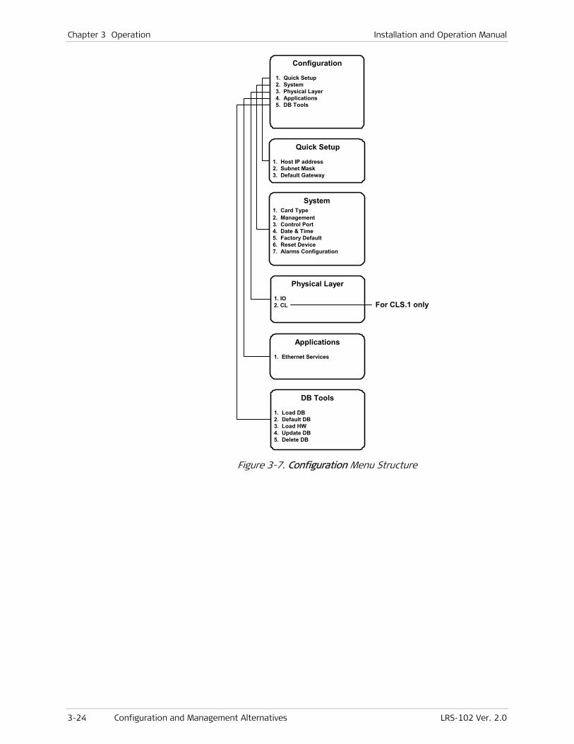
Chapter 3 Operation Installation and Operation Manual
3-24 Configuration and Management Alternatives LRS-102 Ver. 2.0
Configuration
1. Quick Setup 2. System 3. Physical Layer 4. Applications 5. DB Tools
Quick Setup
1. Host IP address 2. Subnet Mask 3. Default Gateway
Physical Layer
1. IO 2. CL
DB Tools
1. Load DB 2. Default DB 3. Load HW 4. Update DB 5. Delete DB
System 1. Card Type 2. Management 3. Control Port 4. Date & Time 5. Factory Default 6. Reset Device 7. Alarms Configuration
Applications
1. Ethernet Services
For CLS.1 only
Figure 3-7. Configuration Menu Structure
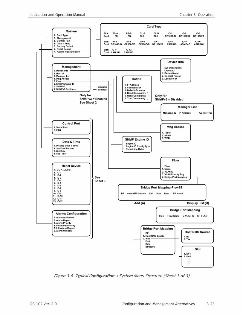
Installation and Operation Manual Chapter 3 Operation
LRS-102 Ver. 2.0 Configuration and Management Alternatives 3-25
Card Type
Slot: PS-A PS-B CL-A CL-B IO-1 IO-2 IO-3 Card: PS PS CL1 CL1 OP108C/B OP108C/B OP106C/B
Slot: IO-4 IO-5 IO-6 IO-7 IO-8 IO-9 IO-10 Card: OP108C/B OP108C/B OP108C/B OP108C/B ASMi54C ASMi54C ASMi54C
Slot: IO-11 IO-12 Card: ASMi54C ASMi54C
Control Port 1. Serial Port 2. ETH
Date & Time 1. Display Date & Time 2. Set Date Format 3. Set Date 4. Set Time
Reset Device 1. CL-A (CL1/ST) 2. IO-1 3. IO-2 4. IO-3 5. IO-4 6. IO-5 7. IO-6 8. IO-7 9. IO-810. IO-911. IO-1012. IO-1113. IO-12
Alarms Configuration 1. Alarm Attributes 2. Alarm Report 3. Alarm Priority 4. Init Alarm Priority 5. Init Alarm Report 6. Alarm Window
Management 1. Device Info 2. Host IP 3. Manager List 4. Mng Access 5. Flow 6. SNMP Engine ID 7. SNMPv3 8. SNMPv3 Setting
Device Info
Sys Description Object ID 1. Device Name 2. Contact Person 3. Location ID
Flow
Flow 1. Name 2. VLAN ID 3. VLAN Priority Tag 4. Bridge Port Mapping
Add (A)
Bridge Port Mapping-Flow251
BP Host NMS Source Slot Port Rate BP Name
Bridge Port Mapping BP 1. Host NMS Source 2. Slot Port Rate BP Name
Host NMS Source 1. No 2. Yes
Slot 1. IO-1 2. IO-4 . . .
Bridge Port Mapping
Flow Flow Name C-VLAN ID SP-VLAN
Display List (U)
System 1. Card Type 2. Management 3. Control Port 4. Date & Time 5. Factory Default 6. Reset Device 7. Alarms Configuration
SeeSheet 3
Host IP
1. IP Address 2. Subnet Mask 3. Default Gateway 4. Read Community 5. Write Community 6. Trap Community
Manager List
Managers ID IP Address Alarms Trap
Mng Access
1. Telnet 2. SNMP 3. WEB
Only forSNMPv3 = EnabledSee Sheet 2
DisabledEnabled
Only forSNMPv3 = Disabled
SNMP Engine ID Engine ID Engine ID Config Type 1. Remaining Bytes
Figure 3-8. Typical Configuration > System Menu Structure (Sheet 1 of 3)
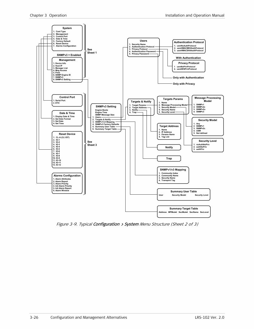
Chapter 3 Operation Installation and Operation Manual
3-26 Configuration and Management Alternatives LRS-102 Ver. 2.0
SeeSheet 1
Control Port 1. Serial Port 2. ETH
Date & Time 1. Display Date & Time 2. Set Date Format 3. Set Date 4. Set Time
Reset Device 1. CL-A (CL1/ST) 2. IO-1 3. IO-2 4. IO-3 5. IO-4 6. IO-5 7. IO-6 8. IO-7 9. IO-810. IO-911. IO-1012. IO-1113. IO-12
Alarms Configuration 1. Alarm Attributes 2. Alarm Report 3. Alarm Priority 4. Init Alarm Priority 5. Init Alarm Report 6. Alarm Window
Management 1. Device Info 2. Host IP 3. Manager List 4. Mng Access 5. Flow 6. SNMP Engine ID 7. SNMPv3 8. SNMPv3 Setting
System 1. Card Type 2. Management 3. Control Port 4. Date & Time 5. Factory Default 6. Reset Device 7. Alarms Configuration
SeeSheet 3
SNMPv3 SettingEngine BootsEngine TimeSNMP Message Size
1. Users2. Targets & Notify3. SNMPv1/v3 Mapping4. SNMPv3 Factory Defaults5. Summary User Table6. Summary Target Table
Users1. Security Name2. Authentication Protocol3. Privacy Protocol4. Authentication Password5. Privacy Password
Targets & Notify1. Target Params2. Target Address3. Notify4. Trap
Targets Params1. Name2. Message Processing Model3. Security Model4. Security Name5. Security Level
Target Address1. Name2. IP Address3. Params Name4. Tag List
Notify
Trap
SNMPv1/v3 Mapping1. Community Index2. Community Name3. Security Name4. Transport Tag
Summary User TableUser Security Model Security Level
Summary Target TableAddress MPModel SecModel SecName SecLevel
Authentication Protocol1. usmNoAuthProtocol2. usmHMACMD5AuthProtocol3. usmHMACSHAAuthProtocol
Privacy Protocol1 usmNoPrivProtocol2. usmDESPrivProtocol
SNMPv3 = EnabledWith Authentication
Only with Authentication
Only with Privacy
Message ProcessingModel
1. SNMPv12. SNMPv2c3. SNMPv2u4. SNMPv3
Security Model1. Any2. SNMPv13. SNMPv2c4. USM5. Not defined
Security Level1. noAuthNoPriv2. authNoPriv3. authPriv
Figure 3-9. Typical Configuration > System Menu Structure (Sheet 2 of 3)
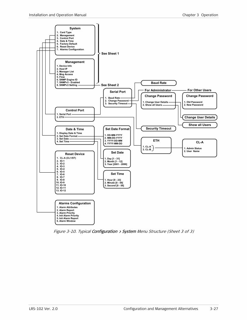
Installation and Operation Manual Chapter 3 Operation
LRS-102 Ver. 2.0 Configuration and Management Alternatives 3-27
See Sheet 1
Serial Port
1. Baud Rate 2. Change Password 3. Security Timeout
Baud Rate
Set Date Format
1. DD-MM-YYYY 2. MM-DD-YYYY 3. YYYY-DD-MM 4. YYYY-MM-DD
ETH
1. CL-A 2. CL-B
CL-A
1. Admin Status 2. User Name
Change Password
1. Change User Details 2. Show all Users
Change User Details
Show all UsersSecurity Timeout
For Administrator
Control Port 1. Serial Port 2. ETH
Date & Time 1. Display Date & Time 2. Set Date Format 3. Set Date 4. Set Time
Reset Device 1. CL-A (CL1/ST) 2. IO-1 3. IO-2 4. IO-3 5. IO-4 6. IO-5 7. IO-6 8. IO-7 9. IO-810. IO-911. IO-1012. IO-1113. IO-12
Alarms Configuration 1. Alarm Attributes 2. Alarm Report 3. Alarm Priority 4. Init Alarm Priority 5. Init Alarm Report 6. Alarm Window
Management 1. Device Info 2. Host IP 3. Manager List 4. Mng Access 5. Flow 6. SNMP Engine ID 7. SNMPv3 - Enabled 8. SNMPv3 Setting
System 1. Card Type 2. Management 3. Control Port 4. Date & Time 5. Factory Default 6. Reset Device 7. Alarms Configuration
See Sheet 2
Change Password
1. Old Password 2. New Password
For Other Users
Set Date
1. Day [1 - 31] 2. Month [1 - 12] 3. Year [2001 - 2099]
Set Time
1. Hour [0 - 23] 2. Minute [0 - 59] 3. Second [0 - 59]
Figure 3-10. Typical Configuration > System Menu Structure (Sheet 3 of 3)

Chapter 3 Operation Installation and Operation Manual
3-28 Configuration and Management Alternatives LRS-102 Ver. 2.0
Station Clock
1. Admin Status 2. Transmit Timing Source 3. Clock Rate 4. Interface Type 5. Line Code 6. Rx Gain Limit 7. SSM 8. Rx Source
Physical Layer
1. I/O 2. CL
I/O
1. I/O-1 2. I/O-2 3. I/O-3 . . . . .
Depends onProgrammed Modules
CL
1. CL-A 2. CL-B
CL-A
1. Station Clock
Transmit TimingSource
1. System 2. Station RCLK 3. Station RCLK after JA
Clock Rate
1. 2048 KBPS 2. 1544 KBPS 2. 2048 KHZ
Short HaulLong Haul
BalanceUnbalance
Line Code
1. AMI 2. HDB3 3. B8ZS
1544 KBPS only2048 KBPS, 2048 KHZ only
CLS.1 only
Only for SSM = Rx and 2048 KBPS
DisableRx
Sa4Sa5Sa6Sa7Sa8
2048 KBPS, 2048 KHZ only
2048 KBPS only
Not for UNBALANCE
Not for SYSTEM
Figure 3-11. Typical Configuration > Physical Layer Menu Structure
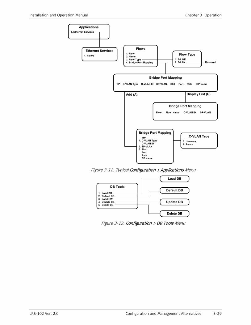
Installation and Operation Manual Chapter 3 Operation
LRS-102 Ver. 2.0 Configuration and Management Alternatives 3-29
Applications 1. Ethernet Services
Ethernet Services 1. Flows
Flows 1. Flow 2. Name 3. Flow Type 4. Bridge Port Mapping
Flow Type 1. E-LINE 2. E-LAN
Add (A)
Bridge Port Mapping
BP C-VLAN Type C-VLAN ID SP-VLAN Slot Port Rate BP Name
C-VLAN Type 1. Unaware 2. Aware
Reserved
Bridge Port Mapping
Flow Flow Name C-VLAN ID SP-VLAN
Display List (U)
Bridge Port Mapping BP 1. C-VLAN Type C-VLAN ID 2. SP-VLAN 3. Slot Port Rate BP Name
Figure 3-12. Typical Configuration > Applications Menu
DB Tools
1. Load DB 2. Default DB 3. Load HW 4. Update DB 5. Delete DB
Load DB
Default DB
Update DB
Delete DB
Figure 3-13. Configuration > DB Tools Menu
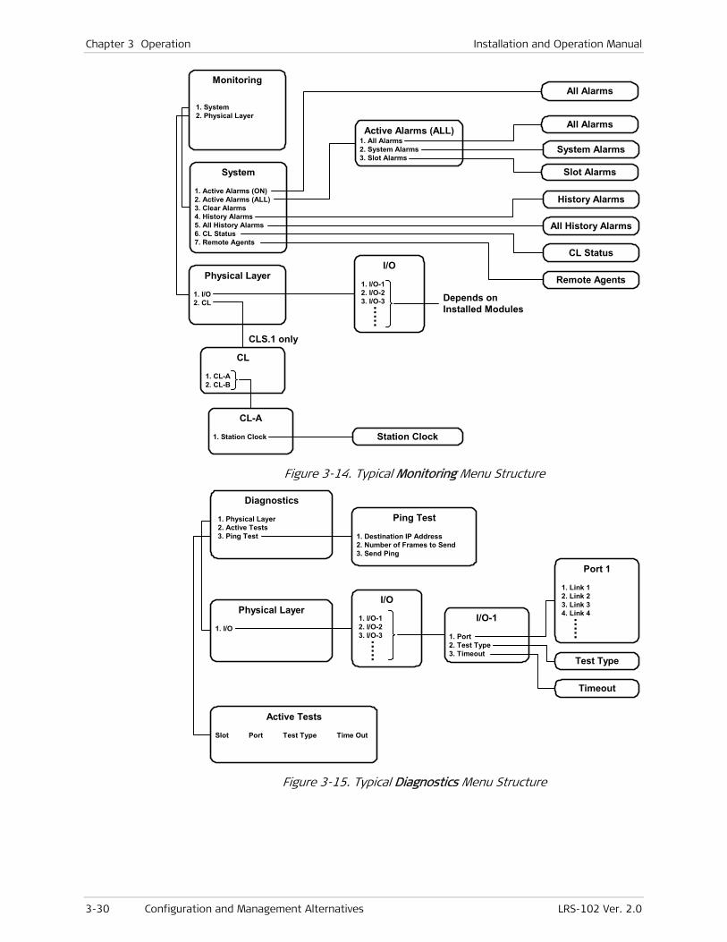
Chapter 3 Operation Installation and Operation Manual
3-30 Configuration and Management Alternatives LRS-102 Ver. 2.0
Monitoring
1. System 2. Physical Layer
System
1. Active Alarms (ON) 2. Active Alarms (ALL) 3. Clear Alarms 4. History Alarms 5. All History Alarms 6. CL Status 7. Remote Agents
History Alarms
All Alarms
Active Alarms (ALL) 1. All Alarms 2. System Alarms 3. Slot Alarms
All Alarms
System Alarms
Slot Alarms
Physical Layer
1. I/O 2. CL
I/O
1. I/O-1 2. I/O-2 3. I/O-3 . . . . .
Depends onInstalled Modules
Remote Agents
CL Status
CL-A
1. Station Clock
CL
1. CL-A 2. CL-B
Station Clock
CLS.1 only
All History Alarms
Figure 3-14. Typical Monitoring Menu Structure
Diagnostics
1. Physical Layer 2. Active Tests 3. Ping Test
Physical Layer
1. I/O
Active Tests
Slot Port Test Type Time Out
I/O-1
1. Port 2. Test Type 3. Timeout
I/O
1. I/O-1 2. I/O-2 3. I/O-3 . . . . .
Port 1
1. Link 1 2. Link 2 3. Link 3 4. Link 4 . . . . .
Test Type
Timeout
Ping Test
1. Destination IP Address 2. Number of Frames to Send 3. Send Ping
Figure 3-15. Typical Diagnostics Menu Structure
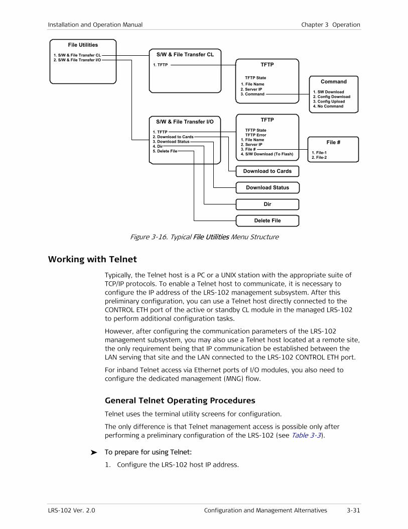
Installation and Operation Manual Chapter 3 Operation
LRS-102 Ver. 2.0 Configuration and Management Alternatives 3-31
TFTP
TFTP State 1. File Name 2. Server IP 3. Command
File Utilities
1. S/W & File Transfer CL 2. S/W & File Transfer I/O
Command
1. SW Download 2. Config Download 3. Config Upload 4. No Command
S/W & File Transfer I/O
1. TFTP 2. Download to Cards 3. Download Status 4. Dir 5. Delete File
TFTP
TFTP State TFTP Error 1. File Name 2. Server IP 3. File # 4. S/W Download (To Flash)
Download to Cards
Dir
Delete File
Download Status
File #
1. File-1 2. File-2
S/W & File Transfer CL
1. TFTP
Figure 3-16. Typical File Utilities Menu Structure
Working with Telnet
Typically, the Telnet host is a PC or a UNIX station with the appropriate suite of TCP/IP protocols. To enable a Telnet host to communicate, it is necessary to configure the IP address of the LRS-102 management subsystem. After this preliminary configuration, you can use a Telnet host directly connected to the CONTROL ETH port of the active or standby CL module in the managed LRS-102 to perform additional configuration tasks.
However, after configuring the communication parameters of the LRS-102 management subsystem, you may also use a Telnet host located at a remote site, the only requirement being that IP communication be established between the LAN serving that site and the LAN connected to the LRS-102 CONTROL ETH port.
For inband Telnet access via Ethernet ports of I/O modules, you also need to configure the dedicated management (MNG) flow.
General Telnet Operating Procedures
Telnet uses the terminal utility screens for configuration.
The only difference is that Telnet management access is possible only after performing a preliminary configuration of the LRS-102 (see Table 3-3).
To prepare for using Telnet:
1. Configure the LRS-102 host IP address.

Chapter 3 Operation Installation and Operation Manual
3-32 Configuration and Management Alternatives LRS-102 Ver. 2.0
When the Telnet host is not on a LAN directly connected to a LRS-102 CONTROL ETH port, it is necessary to configure all the IP communication parameters appearing on the Configuration > System > Management > Host IP screen.
2. Enable Telnet access using Configuration > System > Management > Mng Access > Telnet.
Working with Web Browsers
You may use any Web browser to access the LRS-102 supervision utility from any location that enables access to the LRS-102 using Internet protocols, for example:
• Internet Explorer 6.0 and up, running on Windows™
• Netscape Communicator 7.0 and up, running on Windows™, HPOV or Linux
• Firefox 1.0.4 and up, running on Windows™
• Mozilla 1.4.3 and up, running on Linux.
However, before using Web access, it is necessary to perform a preliminary configuration of the LRS-102 (see Table 3-3).
Guidelines for Using Web Browsers
When using a Web browser, pay attention to the following points:
• Enable scripts
• Configure the firewall that is probably installed on your PC to allow access to the destination IP address (that is, the LRS-102 management address)
• Disable pop-up blocking software (such as Google Popup Blocker); you may also have to configure your spyware/adware protection program to accept traffic from/to the destination IP address.
• Browsers store the last viewed pages in a special cache. To prevent configuration errors, it is absolutely necessary to flush the browser’s cache whenever you return to the same screen.
Preparations for Using Web Browsers
To prepare for using Web access:
1. Configure the LRS-102 host IP address and all the IP communication parameters (use the Configuration > System>Management > Host IP screen).
2. Enable Web browser access using Configuration > System > Management> Mng Access> WEB.
General Web Browser Operating Procedures
Before starting, obtain the LRS-102 management (host) IP address.
1. Open the Web browser.
Note

Installation and Operation Manual Chapter 3 Operation
LRS-102 Ver. 2.0 Configuration and Management Alternatives 3-33
2. Enter the IP address of the LRS-102 in the address field of the browser in the following format: http://’IP address’ (‘IP address’ stands for the actual LRS-102 IP address).
3. After entering the address, press <Enter> to command the browser to connect.
4. After the opening window of the ConfiguRAD utility is displayed, click LOGIN.
5. Perform log-in as described above for the supervision terminal.
6. You will see the main ConfiguRAD menu.
7. Use standard browser operating procedures to perform the desired activities.
Navigating the ConfiguRAD Menus
ConfiguRAD is a Web-based remote access terminal management software. It provides a user-friendly interface for configuring, monitoring and performing diagnostic tests on the LRS-102 units.
To choose an option:
1. Click a link in the ConfiguRAD screen to display the next menu.
2. Once the target screen is displayed, select a value from the drop-down box or enter it in a text box.
3. At the left-hand bottom corner, ConfiguRAD provides some auxiliary management tools:
Status – shows the number of users currently managing LRS-102
Trace – opens an additional pane for system messages, progress indicators (ping, software and configuration file downloads) and alarms. It is recommended to keep the trace pane open all the time.
Refresh All – refreshes all ConfiguRAD display elements.
Working with SNMP Management Stations
Support for SNMP Management
LRS-102 can be configured by any SNMP-based network management station, including third-party network management stations, provided IP communication is possible with the management station.
LRS-102 supports several management information bases (MIBs). A MIB (Management Information Base) is a hierarchically-organized database of managed objects, where each characteristic of the element to be managed is defined as an object in the MIB.
LRS-102 support the following standard MIBs:
• IANAifType-MIB (ifType table)
• RFC4188 (bridge MIB)
• RFC3418 (SNMPv2 MIB)
Chapter 3 Operation Installation and Operation Manual
3-34 Configuration and Management Alternatives LRS-102 Ver. 2.0
• RFC3592 (SONET-MIB)
• RFC3635 (EtherLike-MIB)
• RFC3636 (MAU-MIB)
• RFC4133 (ENTITY-MIB – physicalTable)
• RFC2819 (RMON MIB)
• RFC2863 (IF-MIB)
• RFC4805 (DS1-MIB)
• RFC4319 (HDSL2-SHDSL-LINE-MIB)
• RFC3273 (HC-RMON-MIB)
• RFC4878 (DOT3-OAM-MIB)
• SNMPv1 definitions are covered by the following documents:
RFC3418
RFC2578 (SMIV2)
RFC2579 (Textual Conventions SMIV2)
RFC2580 (Conformance SMIV2).
• SNMPv3 definitions are covered in RFC 3413 to RFC 3418.
LRS-102 also support the RAD private MIB.
Additional MIB information can be obtained from your local RAD Authorized Business Partner.
For information on traps, see Chapter 6.
Preparing for SNMP Management
To enable SNMP management, it is necessary to enable SNMP access, and configure the minimal SNMP management parameters.
The required parameters depend on the required security level:
To prepare for SNMP management without SNMPv3 security features:
1. If necessary, configure SNMPv3 to Disabled. If the previous state has been Enabled, you will be requested to confirm.
2. If necessary, configure the LRS-102 host IP address.
When the SNMP station is not on a LAN directly connected to a LRS-102 CONTROL ETH port, it is necessary to configure all the IP communication parameters appearing on the Configuration > System > Management > Host IP screen.
3. Configure the SNMP community names on the Host IP screen.
4. Enable SNMP access using Configuration > System > Management > Mng Access > SNMP.
Note
Installation and Operation Manual Chapter 3 Operation
LRS-102 Ver. 2.0 Turning the LRS-102 Off 3-35
To prepare for SNMP management with SNMPv3 security features:
1. If necessary, configure SNMPv3 to Enabled. If the previous state has been Disabled, you will be requested to confirm.
2. If necessary, configure the LRS-102 host IP address.
3. Configure SNMPv3 access using Configuration > System > Management > Mng Access > SNMPv3 Setting, using the instructions given in Chapter 4.
4. Enable SNMP access using Configuration > System > Management > Mng Access > SNMP.
For SNMP management instructions, refer to the User’s Guide of the desired SNMP station.
3.5 Turning the LRS-102 Off
To turn the LRS-102 off:
1. Disconnect the power cables, or turn off the power by means of an external switch or circuit breaker.

Chapter 3 Operation Installation and Operation Manual
3-36 Turning the LRS-102 Off LRS-102 Ver. 2.0

LRS-102 Ver. 2.0 Managing LRS-102 Configuration Databases 4-1
Chapter 4
Configuration
This Chapter provides detailed configuration instructions for the LRS-102, including the purpose and the parameters that can be selected on the each screen, instructions for using each screen, considerations regarding the selection of specific parameter values, and where applicable, the effects of parameters selected on other screens
The information is organized as follows:
• Managing LRS-102 configuration databases – Section 4.1
• Configuration system parameters – Section 4.2
• Configuring LRS-102 for SNMP management –Section 4.3
• Configuring physical layer parameters – Section 4.4
• Configuring Ethernet applications – Section 4.5
• Using LRS-102 file utilities – Section 4.6
• Viewing logistic information – Section 4.7
Before starting, you may also want to review Chapter 1, which presents technical and functional descriptions of the LRS-102.
You can find a complete collection of supervision utility navigation maps in Chapter 3. For your convenience, the relevant navigation map also appears in the beginning section of each main configuration activity.
The configuration instructions are presented in the order the configuration activities are performed when a new LRS-102 is prepared for service (see Chapter 5 for a detailed configuration sequence).
The information appearing in this Chapter assumes that you are familiar with the general operating instructions for the supervision utility, as described in Chapter 3.
However, after performing the preliminary configuration of the LRS-102 in accordance with Chapter 3, the same configuration activities can also be performed by means of a Telnet host or Web browser.
If you configure LRS-102 for SNMP management as explained in this Chapter, SNMP management stations using the appropriate SNMP version and compatible parameters will also be able to configure and manage LRS-102 units.
Unless otherwise specified, all the parameter values appearing in the following screens are given for illustration purposes only. They do not reflect recommended values.
Note

Chapter 4 Configuration Installation and Operation Manual
4-2 Managing LRS-102 Configuration Databases LRS-102 Ver. 2.0
4.1 Managing LRS-102 Configuration Databases
Before starting configuration activities, it is important to understand the LRS-102 database tools (reached from the DB Tools menu), used to manage LRS-102 databases.
Normally, only one database is needed to store the LRS-102 configuration parameters. However, LRS-102 can store a few databases in the CL module flash memory, and therefore, when necessary, it is possible to prepare additional databases with alternative configurations, and store them in the LRS-102 flash memory for immediate availability. LRS-102 databases are assigned index numbers in the range of 1 to 10.
Therefore, the following terms are used in respect to LRS-102 databases:
• Online database file: one database file, which is always assigned index number 1, serves as the current online (active) database. This is the file from which parameters have been downloaded to the LRS-102 modules, and therefore it determines the current LRS-102 operation configuration.
• All the other database files are simply stored in the flash memory. These files may have been created by the user using the database tools or the file system utilities, or received by TFTP from a remote host or management station.
A copy of the online database is normally loaded into the CL module edit buffer. The contents of the edit buffer are preserved until the LRS-102 is powered down: on the next power-up, the edit buffer is again loaded with a copy of the online database and therefore any unsaved changes are lost.
Any authorized user (including operators of management stations, etc.) can work on the edit buffer without affecting the online database, for example:
• Make changes to the database copy located in the edit buffer
• Replace the edit buffer contents with the factory defaults
• Load into the edit buffer another database file, thus also replacing the current contents with new contents.
A desired database can be created or updated by a dedicated Update DB command, which performs the following actions:
1. Initiates a sanity check on the edit buffer contents, and reports errors and warnings.
2. If no errors are detected, saves the edit buffer contents to a specified database (the database number is selected by the user).
Normally, changes are saved to the active, or online, database. In this case, after successfully saving the buffer contents to flash memory, configuration messages are automatically sent to the LRS-102 subsystems to change their operating mode in accordance with the new online database. As mentioned above, the number of the active database is always 1, irrespective of the number of the database loaded into the edit buffer as a basis for changes.
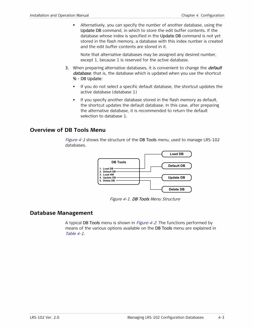
Installation and Operation Manual Chapter 4 Configuration
LRS-102 Ver. 2.0 Managing LRS-102 Configuration Databases 4-3
Alternatively, you can specify the number of another database, using the Update DB command, in which to store the edit buffer contents. If the database whose index is specified in the Update DB command is not yet stored in the flash memory, a database with this index number is created and the edit buffer contents are stored in it.
Note that alternative databases may be assigned any desired number, except 1, because 1 is reserved for the active database.
3. When preparing alternative databases, it is convenient to change the default database, that is, the database which is updated when you use the shortcut % - DB Update:
If you do not select a specific default database, the shortcut updates the active database (database 1)
If you specify another database stored in the flash memory as default, the shortcut updates the default database. In this case, after preparing the alternative database, it is recommended to return the default selection to database 1.
Overview of DB Tools Menu
Figure 4-1 shows the structure of the DB Tools menu, used to manage LRS-102 databases.
DB Tools
1. Load DB 2. Default DB 3. Load HW 4. Update DB 5. Delete DB
Load DB
Default DB
Update DB
Delete DB
Figure 4-1. DB Tools Menu Structure
Database Management
A typical DB Tools menu is shown in Figure 4-2. The functions performed by means of the various options available on the DB Tools menu are explained in Table 4-1.
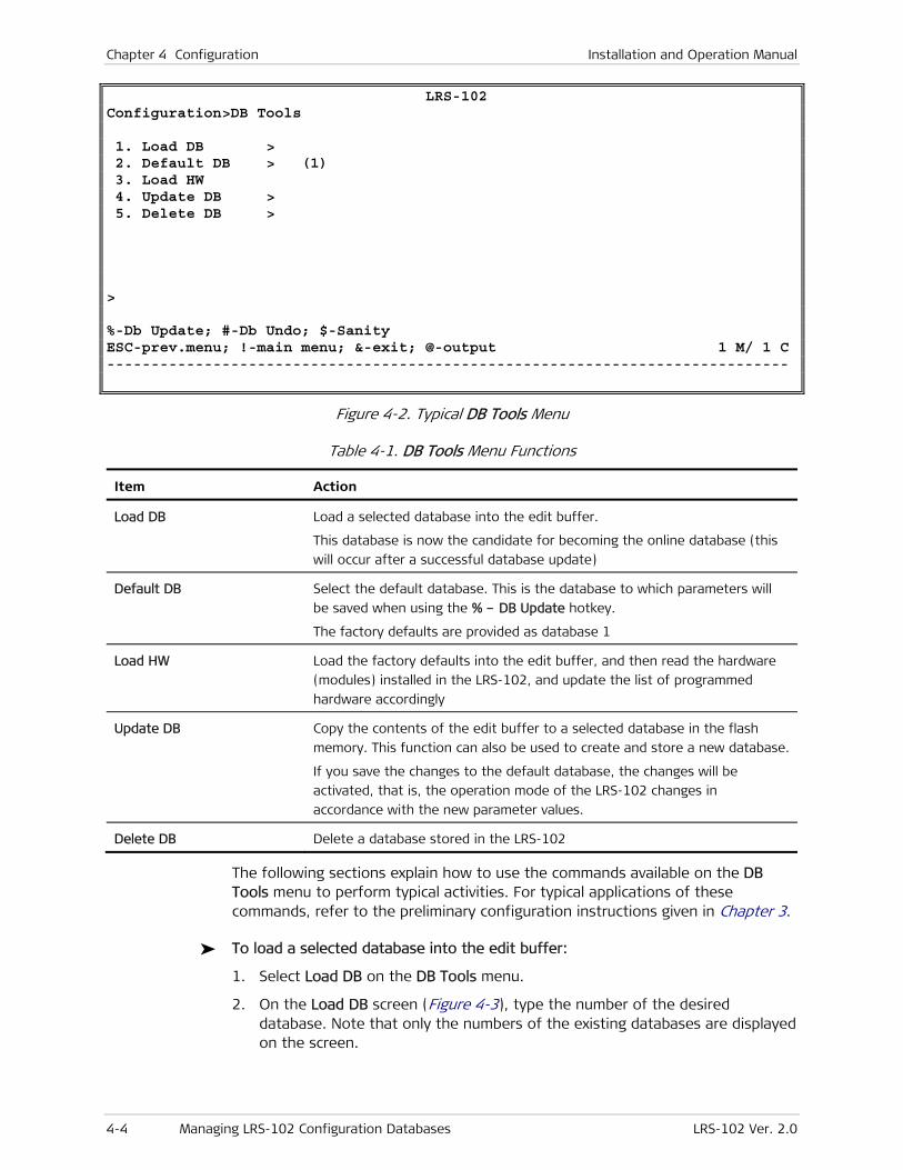
Chapter 4 Configuration Installation and Operation Manual
4-4 Managing LRS-102 Configuration Databases LRS-102 Ver. 2.0
LRS-102 Configuration>DB Tools 1. Load DB > 2. Default DB > (1) 3. Load HW 4. Update DB > 5. Delete DB > > %-Db Update; #-Db Undo; $-Sanity ESC-prev.menu; !-main menu; &-exit; @-output 1 M/ 1 C -----------------------------------------------------------------------------
Figure 4-2. Typical DB Tools Menu
Table 4-1. DB Tools Menu Functions
Item Action
Load DB Load a selected database into the edit buffer.
This database is now the candidate for becoming the online database (this
will occur after a successful database update)
Default DB Select the default database. This is the database to which parameters will
be saved when using the % – DB Update hotkey.
The factory defaults are provided as database 1
Load HW Load the factory defaults into the edit buffer, and then read the hardware
(modules) installed in the LRS-102, and update the list of programmed
hardware accordingly
Update DB Copy the contents of the edit buffer to a selected database in the flash
memory. This function can also be used to create and store a new database.
If you save the changes to the default database, the changes will be
activated, that is, the operation mode of the LRS-102 changes in
accordance with the new parameter values.
Delete DB Delete a database stored in the LRS-102
The following sections explain how to use the commands available on the DB Tools menu to perform typical activities. For typical applications of these commands, refer to the preliminary configuration instructions given in Chapter 3.
To load a selected database into the edit buffer:
1. Select Load DB on the DB Tools menu.
2. On the Load DB screen (Figure 4-3), type the number of the desired database. Note that only the numbers of the existing databases are displayed on the screen.
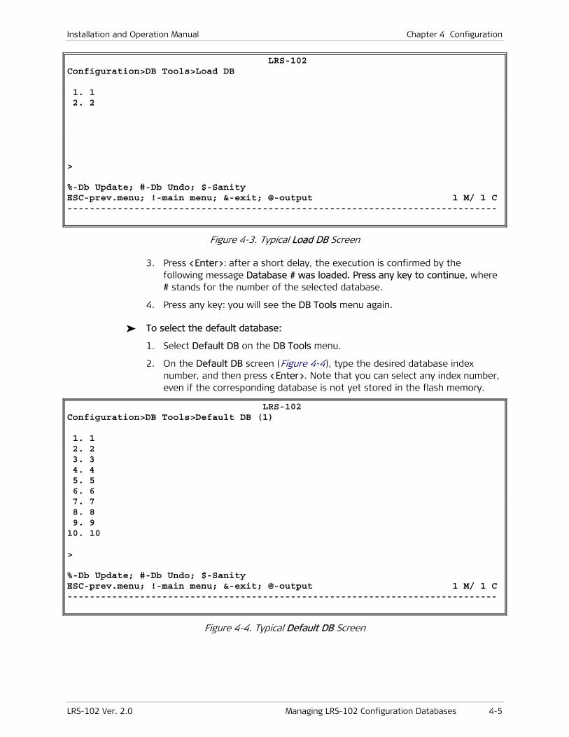
Installation and Operation Manual Chapter 4 Configuration
LRS-102 Ver. 2.0 Managing LRS-102 Configuration Databases 4-5
LRS-102 Configuration>DB Tools>Load DB 1. 1 2. 2 > %-Db Update; #-Db Undo; $-Sanity ESC-prev.menu; !-main menu; &-exit; @-output 1 M/ 1 C -----------------------------------------------------------------------------
Figure 4-3. Typical Load DB Screen
3. Press <Enter>: after a short delay, the execution is confirmed by the following message Database # was loaded. Press any key to continue, where # stands for the number of the selected database.
4. Press any key: you will see the DB Tools menu again.
To select the default database:
1. Select Default DB on the DB Tools menu.
2. On the Default DB screen (Figure 4-4), type the desired database index number, and then press <Enter>. Note that you can select any index number, even if the corresponding database is not yet stored in the flash memory.
LRS-102 Configuration>DB Tools>Default DB (1) 1. 1 2. 2 3. 3 4. 4 5. 5 6. 6 7. 7 8. 8 9. 9 10. 10 > %-Db Update; #-Db Undo; $-Sanity ESC-prev.menu; !-main menu; &-exit; @-output 1 M/ 1 C -----------------------------------------------------------------------------
Figure 4-4. Typical Default DB Screen
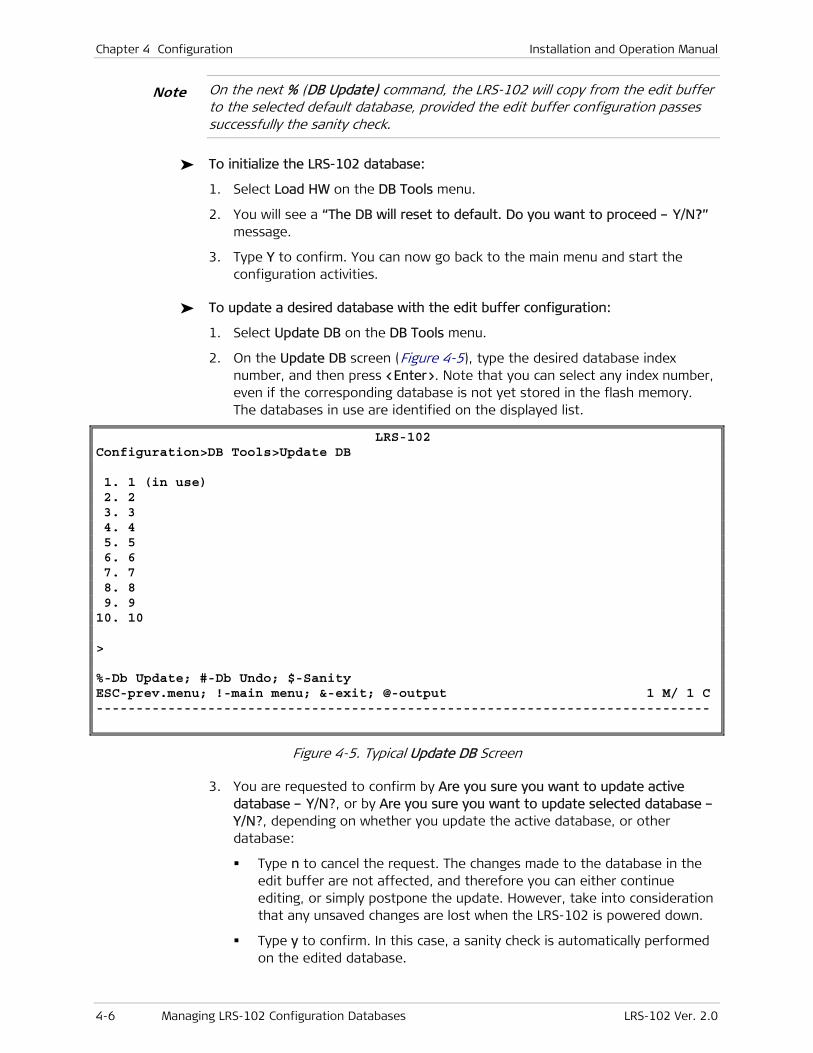
Chapter 4 Configuration Installation and Operation Manual
4-6 Managing LRS-102 Configuration Databases LRS-102 Ver. 2.0
On the next % (DB Update) command, the LRS-102 will copy from the edit buffer to the selected default database, provided the edit buffer configuration passes successfully the sanity check.
To initialize the LRS-102 database:
1. Select Load HW on the DB Tools menu.
2. You will see a “The DB will reset to default. Do you want to proceed – Y/N?” message.
3. Type Y to confirm. You can now go back to the main menu and start the configuration activities.
To update a desired database with the edit buffer configuration:
1. Select Update DB on the DB Tools menu.
2. On the Update DB screen (Figure 4-5), type the desired database index number, and then press <Enter>. Note that you can select any index number, even if the corresponding database is not yet stored in the flash memory. The databases in use are identified on the displayed list.
LRS-102 Configuration>DB Tools>Update DB 1. 1 (in use) 2. 2 3. 3 4. 4 5. 5 6. 6 7. 7 8. 8 9. 9 10. 10 > %-Db Update; #-Db Undo; $-Sanity ESC-prev.menu; !-main menu; &-exit; @-output 1 M/ 1 C -----------------------------------------------------------------------------
Figure 4-5. Typical Update DB Screen
3. You are requested to confirm by Are you sure you want to update active database – Y/N?, or by Are you sure you want to update selected database – Y/N?, depending on whether you update the active database, or other database:
Type n to cancel the request. The changes made to the database in the edit buffer are not affected, and therefore you can either continue editing, or simply postpone the update. However, take into consideration that any unsaved changes are lost when the LRS-102 is powered down.
Type y to confirm. In this case, a sanity check is automatically performed on the edited database.
Note
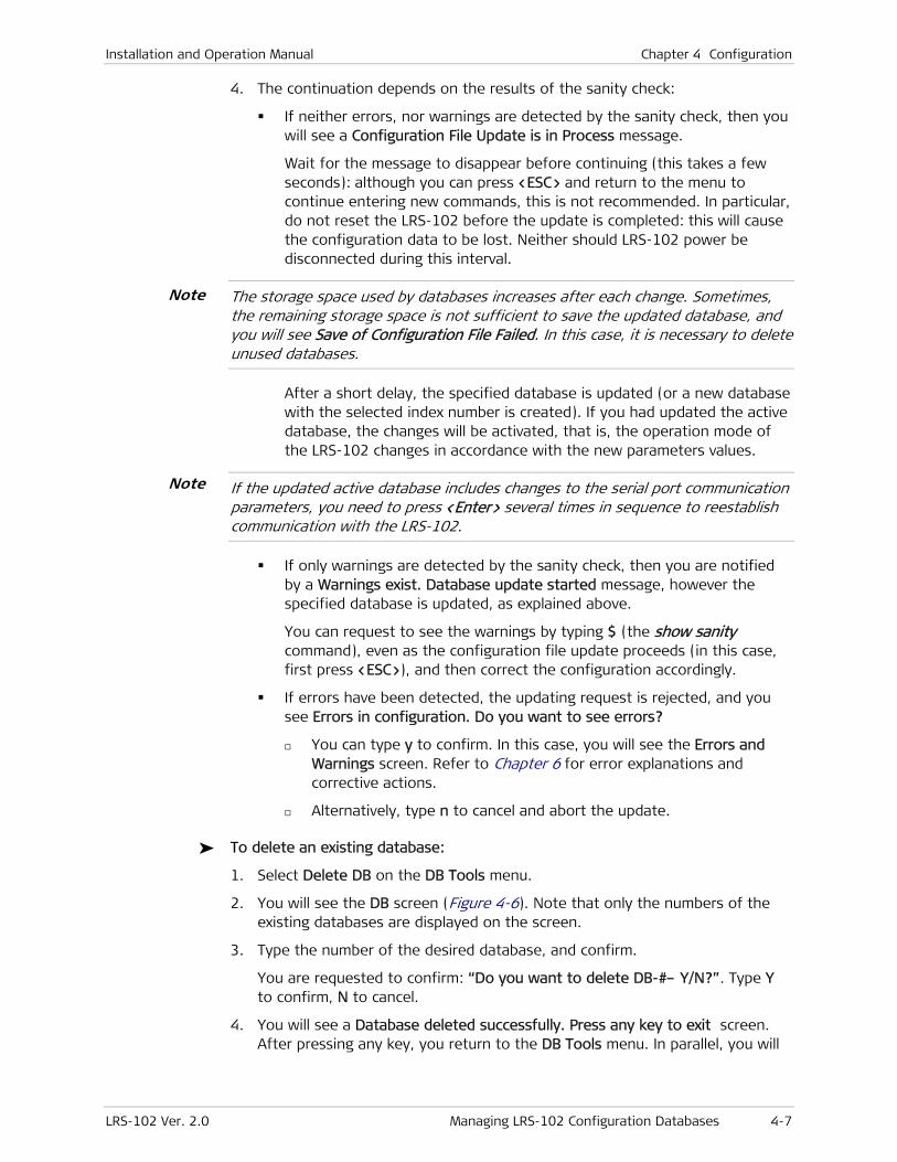
Installation and Operation Manual Chapter 4 Configuration
LRS-102 Ver. 2.0 Managing LRS-102 Configuration Databases 4-7
4. The continuation depends on the results of the sanity check:
If neither errors, nor warnings are detected by the sanity check, then you will see a Configuration File Update is in Process message.
Wait for the message to disappear before continuing (this takes a few seconds): although you can press <ESC> and return to the menu to continue entering new commands, this is not recommended. In particular, do not reset the LRS-102 before the update is completed: this will cause the configuration data to be lost. Neither should LRS-102 power be disconnected during this interval.
The storage space used by databases increases after each change. Sometimes, the remaining storage space is not sufficient to save the updated database, and you will see Save of Configuration File Failed. In this case, it is necessary to delete unused databases.
After a short delay, the specified database is updated (or a new database with the selected index number is created). If you had updated the active database, the changes will be activated, that is, the operation mode of the LRS-102 changes in accordance with the new parameters values.
If the updated active database includes changes to the serial port communication parameters, you need to press <Enter> several times in sequence to reestablish communication with the LRS-102.
If only warnings are detected by the sanity check, then you are notified by a Warnings exist. Database update started message, however the specified database is updated, as explained above.
You can request to see the warnings by typing $ (the show sanity command), even as the configuration file update proceeds (in this case, first press <ESC>), and then correct the configuration accordingly.
If errors have been detected, the updating request is rejected, and you see Errors in configuration. Do you want to see errors?
You can type y to confirm. In this case, you will see the Errors and Warnings screen. Refer to Chapter 6 for error explanations and corrective actions.
Alternatively, type n to cancel and abort the update.
To delete an existing database:
1. Select Delete DB on the DB Tools menu.
2. You will see the DB screen (Figure 4-6). Note that only the numbers of the existing databases are displayed on the screen.
3. Type the number of the desired database, and confirm.
You are requested to confirm: “Do you want to delete DB-#– Y/N?”. Type Y to confirm, N to cancel.
4. You will see a Database deleted successfully. Press any key to exit screen. After pressing any key, you return to the DB Tools menu. In parallel, you will
Note
Note
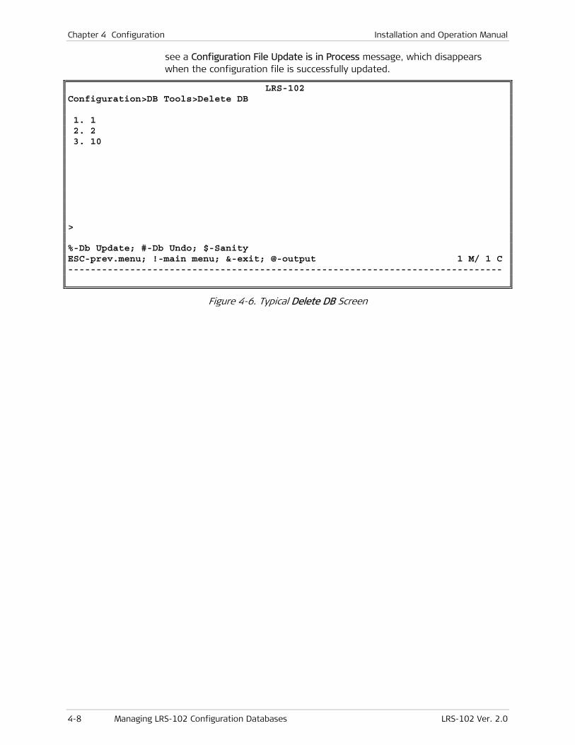
Chapter 4 Configuration Installation and Operation Manual
4-8 Managing LRS-102 Configuration Databases LRS-102 Ver. 2.0
see a Configuration File Update is in Process message, which disappears when the configuration file is successfully updated.
LRS-102 Configuration>DB Tools>Delete DB 1. 1 2. 2 3. 10 > %-Db Update; #-Db Undo; $-Sanity ESC-prev.menu; !-main menu; &-exit; @-output 1 M/ 1 C -----------------------------------------------------------------------------
Figure 4-6. Typical Delete DB Screen

Installation and Operation Manual Chapter 4 Configuration
LRS-102 Ver. 2.0 Configuring System Parameters 4-9
4.2 Configuring System Parameters
To configure the system parameters:
5. Use Configuration > Quick Setup to configure the basic LRS-102 IP communication parameters.
6. Use the Configuration > System submenu to perform the following activities:
1. If necessary, reload factory defaults to start the configuration from a known baseline.
2. Program the modules installed in the LRS-102 chassis.
3. Configure the LRS-102 serial control port, and the authorizations of the users allowed to use the serial port.
4. Configure the LRS-102 Ethernet control port.
5. Select the SNMP support mode (SNMPv3 security features enabled or disabled).
6. Configure LRS-102 management parameters, and management access authorizations.
Configuration instructions for SNMP management appear in Section 4.3.
7. Configure system logistic information.
8. Set system time-of-day and date.
Overview of System Configuration Submenu
Figure 4-7 and Figure 4-8 show the detailed structure of the System submenu.
In addition to the configuration activities listed in this section, the System submenu provides access to additional system-level configuration activities that are covered by other sections in this manual.
Note

Chapter 4 Configuration Installation and Operation Manual
4-10 Configuring System Parameters LRS-102 Ver. 2.0
Card Type
Slot: PS-A PS-B CL-A CL-B IO-1 IO-2 IO-3 Card: PS PS CL1 CL1 OP108C/B OP108C/B OP106C/B
Slot: IO-4 IO-5 IO-6 IO-7 IO-8 IO-9 IO-10 Card: OP108C/B OP108C/B OP108C/B OP108C/B ASMi54C ASMi54C ASMi54C
Slot: IO-11 IO-12 Card: ASMi54C ASMi54C
Control Port 1. Serial Port 2. ETH
Date & Time 1. Display Date & Time 2. Set Date Format 3. Set Date 4. Set Time
Reset Device 1. CL-A (CL1/ST) 2. IO-1 3. IO-2 4. IO-3 5. IO-4 6. IO-5 7. IO-6 8. IO-7 9. IO-810. IO-911. IO-1012. IO-1113. IO-12
Alarms Configuration 1. Alarm Attributes 2. Alarm Report 3. Alarm Priority 4. Init Alarm Priority 5. Init Alarm Report 6. Alarm Window
Management 1. Device Info 2. Host IP 3. Manager List 4. Mng Access 5. Flow 6. SNMP Engine ID 7. SNMPv3 8. SNMPv3 Setting
Device Info
Sys Description Object ID 1. Device Name 2. Contact Person 3. Location ID
Flow
Flow 1. Name 2. VLAN ID 3. VLAN Priority Tag 4. Bridge Port Mapping
Add (A)
Bridge Port Mapping-Flow251
BP Host NMS Source Slot Port Rate BP Name
Bridge Port Mapping BP 1. Host NMS Source 2. Slot Port Rate BP Name
Host NMS Source 1. No 2. Yes
Slot 1. IO-1 2. IO-4 . . .
Bridge Port Mapping
Flow Flow Name C-VLAN ID SP-VLAN
Display List (U)
System 1. Card Type 2. Management 3. Control Port 4. Date & Time 5. Factory Default 6. Reset Device 7. Alarms Configuration
SeeSheet 3
Host IP
1. IP Address 2. Subnet Mask 3. Default Gateway 4. Read Community 5. Write Community 6. Trap Community
Manager List
Managers ID IP Address Alarms Trap
Mng Access
1. Telnet 2. SNMP 3. WEB
Only forSNMPv3 = EnabledSee Sheet 2
DisabledEnabled
Only forSNMPv3 = Disabled
SNMP Engine ID Engine ID Engine ID Config Type 1. Remaining Bytes
Figure 4-7. Typical Configuration > System Submenu Structure (Sheet 1 of 3)
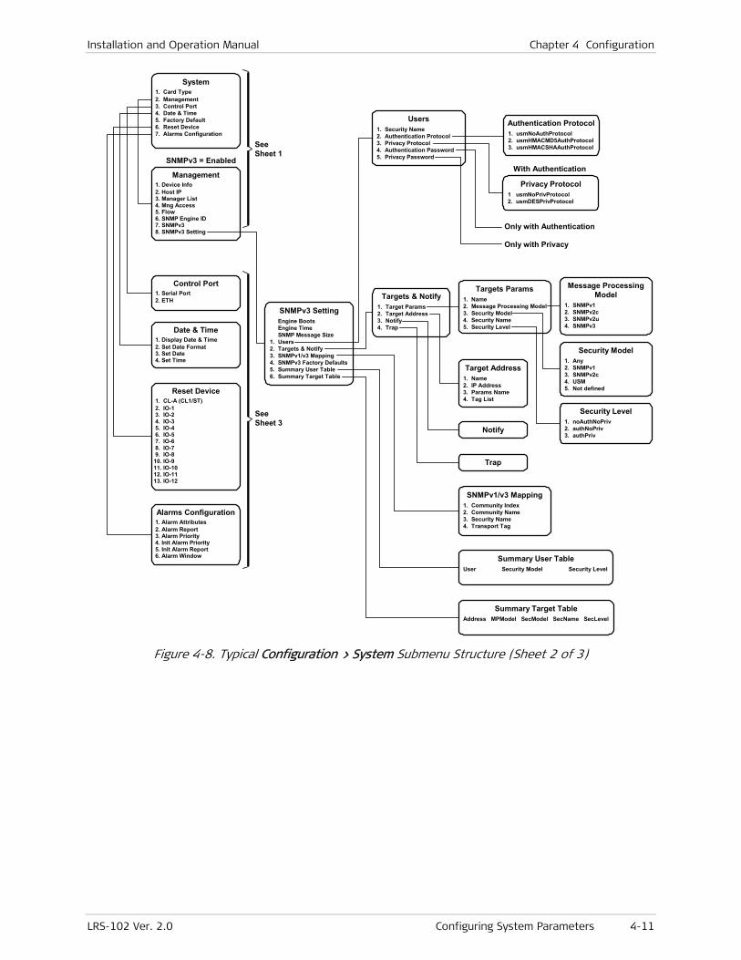
Installation and Operation Manual Chapter 4 Configuration
LRS-102 Ver. 2.0 Configuring System Parameters 4-11
SeeSheet 1
Control Port 1. Serial Port 2. ETH
Date & Time 1. Display Date & Time 2. Set Date Format 3. Set Date 4. Set Time
Reset Device 1. CL-A (CL1/ST) 2. IO-1 3. IO-2 4. IO-3 5. IO-4 6. IO-5 7. IO-6 8. IO-7 9. IO-810. IO-911. IO-1012. IO-1113. IO-12
Alarms Configuration 1. Alarm Attributes 2. Alarm Report 3. Alarm Priority 4. Init Alarm Priority 5. Init Alarm Report 6. Alarm Window
Management 1. Device Info 2. Host IP 3. Manager List 4. Mng Access 5. Flow 6. SNMP Engine ID 7. SNMPv3 8. SNMPv3 Setting
System 1. Card Type 2. Management 3. Control Port 4. Date & Time 5. Factory Default 6. Reset Device 7. Alarms Configuration
SeeSheet 3
SNMPv3 SettingEngine BootsEngine TimeSNMP Message Size
1. Users2. Targets & Notify3. SNMPv1/v3 Mapping4. SNMPv3 Factory Defaults5. Summary User Table6. Summary Target Table
Users1. Security Name2. Authentication Protocol3. Privacy Protocol4. Authentication Password5. Privacy Password
Targets & Notify1. Target Params2. Target Address3. Notify4. Trap
Targets Params1. Name2. Message Processing Model3. Security Model4. Security Name5. Security Level
Target Address1. Name2. IP Address3. Params Name4. Tag List
Notify
Trap
SNMPv1/v3 Mapping1. Community Index2. Community Name3. Security Name4. Transport Tag
Summary User TableUser Security Model Security Level
Summary Target TableAddress MPModel SecModel SecName SecLevel
Authentication Protocol1. usmNoAuthProtocol2. usmHMACMD5AuthProtocol3. usmHMACSHAAuthProtocol
Privacy Protocol1 usmNoPrivProtocol2. usmDESPrivProtocol
SNMPv3 = EnabledWith Authentication
Only with Authentication
Only with Privacy
Message ProcessingModel
1. SNMPv12. SNMPv2c3. SNMPv2u4. SNMPv3
Security Model1. Any2. SNMPv13. SNMPv2c4. USM5. Not defined
Security Level1. noAuthNoPriv2. authNoPriv3. authPriv
Figure 4-8. Typical Configuration > System Submenu Structure (Sheet 2 of 3)
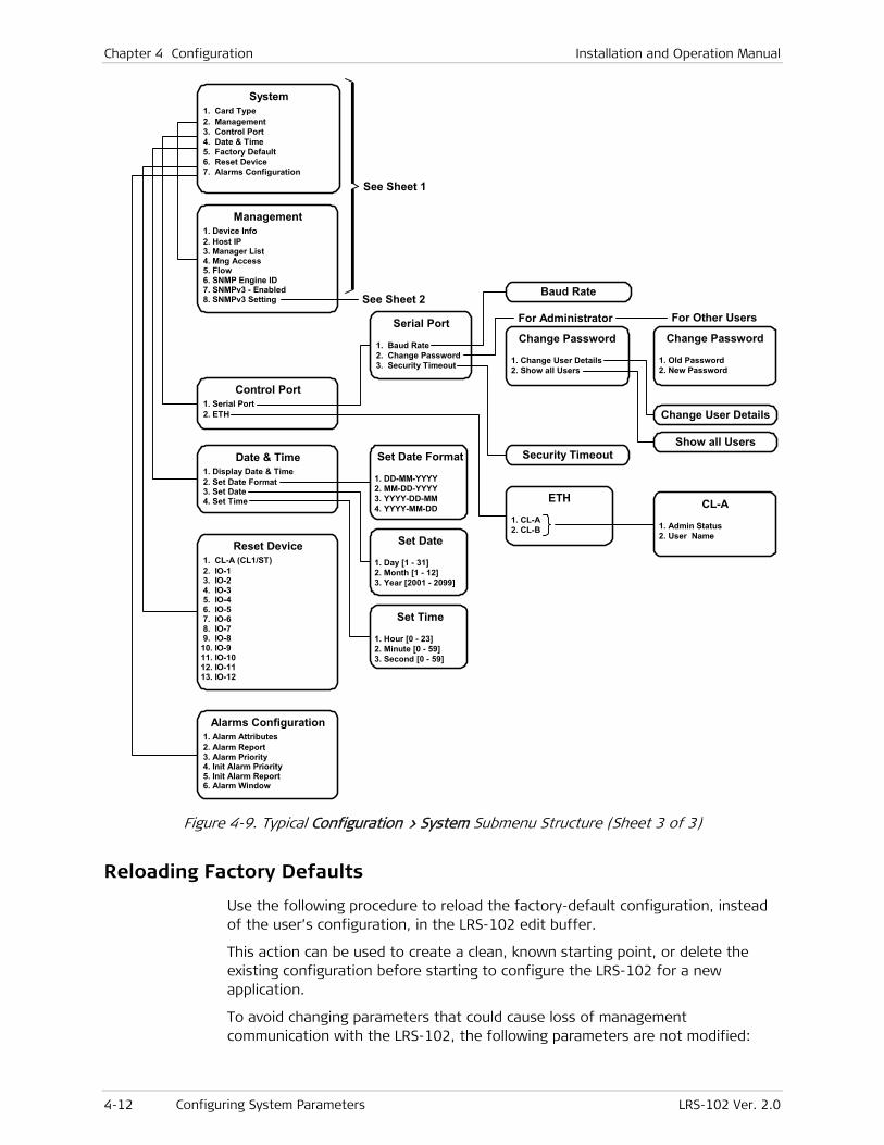
Chapter 4 Configuration Installation and Operation Manual
4-12 Configuring System Parameters LRS-102 Ver. 2.0
See Sheet 1
Serial Port
1. Baud Rate 2. Change Password 3. Security Timeout
Baud Rate
Set Date Format
1. DD-MM-YYYY 2. MM-DD-YYYY 3. YYYY-DD-MM 4. YYYY-MM-DD
ETH
1. CL-A 2. CL-B
CL-A
1. Admin Status 2. User Name
Change Password
1. Change User Details 2. Show all Users
Change User Details
Show all UsersSecurity Timeout
For Administrator
Control Port 1. Serial Port 2. ETH
Date & Time 1. Display Date & Time 2. Set Date Format 3. Set Date 4. Set Time
Reset Device 1. CL-A (CL1/ST) 2. IO-1 3. IO-2 4. IO-3 5. IO-4 6. IO-5 7. IO-6 8. IO-7 9. IO-810. IO-911. IO-1012. IO-1113. IO-12
Alarms Configuration 1. Alarm Attributes 2. Alarm Report 3. Alarm Priority 4. Init Alarm Priority 5. Init Alarm Report 6. Alarm Window
Management 1. Device Info 2. Host IP 3. Manager List 4. Mng Access 5. Flow 6. SNMP Engine ID 7. SNMPv3 - Enabled 8. SNMPv3 Setting
System 1. Card Type 2. Management 3. Control Port 4. Date & Time 5. Factory Default 6. Reset Device 7. Alarms Configuration
See Sheet 2
Change Password
1. Old Password 2. New Password
For Other Users
Set Date
1. Day [1 - 31] 2. Month [1 - 12] 3. Year [2001 - 2099]
Set Time
1. Hour [0 - 23] 2. Minute [0 - 59] 3. Second [0 - 59]
Figure 4-9. Typical Configuration > System Submenu Structure (Sheet 3 of 3)
Reloading Factory Defaults
Use the following procedure to reload the factory-default configuration, instead of the user’s configuration, in the LRS-102 edit buffer.
This action can be used to create a clean, known starting point, or delete the existing configuration before starting to configure the LRS-102 for a new application.
To avoid changing parameters that could cause loss of management communication with the LRS-102, the following parameters are not modified:

Installation and Operation Manual Chapter 4 Configuration
LRS-102 Ver. 2.0 Configuring System Parameters 4-13
• IP addresses, and all the management parameters
• Control port parameters.
To navigate to the required screen, use Configuration > System > Factory Default.
To reload the factory-default parameters:
1. Select Factory Default on the System menu.
2. You will see DB values will change to defaults. Are you sure?:
To abort, type n.
To confirm, type y.
3. If you confirmed, you must save the new configuration before it is actually activated:
If you change your mind, undo by typing #.
To activate the default configuration, type % (the DB Update command). In this case, You will see Are you sure you want to update active database – Y/N? and therefore you must confirm again:
To abort, type n.
To confirm, type y.
4. At this stage, the LRS-102 switches to the default parameters.
Usually, you must press <Enter> before you see again the menu.
However, if the LRS-102 did not use the default supervisory port communication parameters, then before you can establish again communication with the LRS-102 you must change the supervisory terminal communication parameters to the default values: 115.2 kbps, one start bit, eight data bits, no parity, one stop bit and VT-100 terminal emulation.
Reset Device
Use the following procedure to reset the LRS-102 (that is, reset all the modules installed in the chassis, including the CL modules), or a specific I/O module. Resetting does not affect the configuration data changed by the user, not even if it has not yet saved.
To navigate to the required screen, use Configuration > System > Reset Device.
To reset the LRS-102:
1. Select Reset Device on the System menu.
2. Select CL-A or CL-B on the list (only the active CL module can be selected), and then press <Enter>.
3. You will see The device will restart. Do you want to proceed – Y/N?:
To abort, type n.
To confirm, type y.
4. At this stage, the LRS-102 is reset.
Note
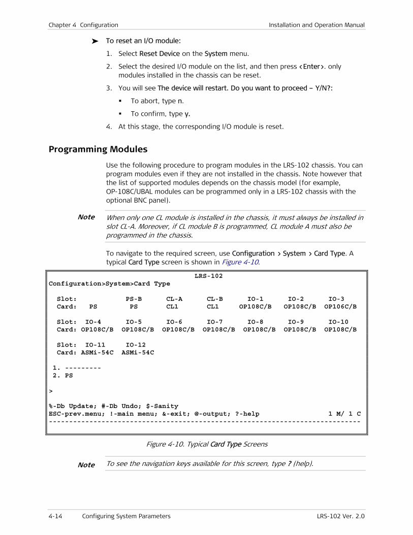
Chapter 4 Configuration Installation and Operation Manual
4-14 Configuring System Parameters LRS-102 Ver. 2.0
To reset an I/O module:
1. Select Reset Device on the System menu.
2. Select the desired I/O module on the list, and then press <Enter>. only modules installed in the chassis can be reset.
3. You will see The device will restart. Do you want to proceed – Y/N?:
To abort, type n.
To confirm, type y.
4. At this stage, the corresponding I/O module is reset.
Programming Modules
Use the following procedure to program modules in the LRS-102 chassis. You can program modules even if they are not installed in the chassis. Note however that the list of supported modules depends on the chassis model (for example, OP-108C/UBAL modules can be programmed only in a LRS-102 chassis with the optional BNC panel).
When only one CL module is installed in the chassis, it must always be installed in slot CL-A. Moreover, if CL module B is programmed, CL module A must also be programmed in the chassis.
To navigate to the required screen, use Configuration > System > Card Type. A typical Card Type screen is shown in Figure 4-10.
LRS-102 Configuration>System>Card Type Slot: PS-A PS-B CL-A CL-B IO-1 IO-2 IO-3 Card: PS PS CL1 CL1 OP108C/B OP108C/B OP106C/B Slot: IO-4 IO-5 IO-6 IO-7 IO-8 IO-9 IO-10 Card: OP108C/B OP108C/B OP108C/B OP108C/B OP108C/B OP108C/B OP108C/B Slot: IO-11 IO-12 Card: ASMi-54C ASMi-54C 1. --------- 2. PS > %-Db Update; #-Db Undo; $-Sanity ESC-prev.menu; !-main menu; &-exit; @-output; ?-help 1 M/ 1 C -----------------------------------------------------------------------------
Figure 4-10. Typical Card Type Screens
To see the navigation keys available for this screen, type ? (help).
Note
Note
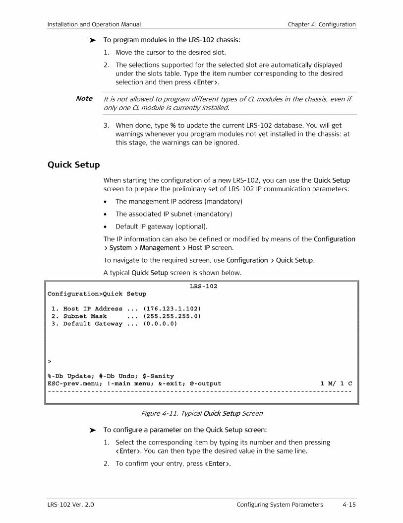
Installation and Operation Manual Chapter 4 Configuration
LRS-102 Ver. 2.0 Configuring System Parameters 4-15
To program modules in the LRS-102 chassis:
1. Move the cursor to the desired slot.
2. The selections supported for the selected slot are automatically displayed under the slots table. Type the item number corresponding to the desired selection and then press <Enter>.
It is not allowed to program different types of CL modules in the chassis, even if only one CL module is currently installed.
3. When done, type % to update the current LRS-102 database. You will get warnings whenever you program modules not yet installed in the chassis: at this stage, the warnings can be ignored.
Quick Setup
When starting the configuration of a new LRS-102, you can use the Quick Setup screen to prepare the preliminary set of LRS-102 IP communication parameters:
• The management IP address (mandatory)
• The associated IP subnet (mandatory)
• Default IP gateway (optional).
The IP information can also be defined or modified by means of the Configuration > System > Management > Host IP screen.
To navigate to the required screen, use Configuration > Quick Setup.
A typical Quick Setup screen is shown below.
LRS-102 Configuration>Quick Setup 1. Host IP Address ... (176.123.1.102) 2. Subnet Mask ... (255.255.255.0) 3. Default Gateway ... (0.0.0.0) > %-Db Update; #-Db Undo; $-Sanity ESC-prev.menu; !-main menu; &-exit; @-output 1 M/ 1 C -----------------------------------------------------------------------------
Figure 4-11. Typical Quick Setup Screen
To configure a parameter on the Quick Setup screen:
1. Select the corresponding item by typing its number and then pressing <Enter>. You can then type the desired value in the same line.
2. To confirm your entry, press <Enter>.
Note
Chapter 4 Configuration Installation and Operation Manual
4-16 Configuring System Parameters LRS-102 Ver. 2.0
To configure the LRS-102 management IP address:
1. Select Host IP address.
2. Enter the prescribed IP address of the LRS-102 management agent, in the dotted quad format, and then press <Enter>.
3. Select Subnet Mask.
4. Enter the IP subnet mask to be used by of the LRS-102 management agent, in the dotted quad format, and then press <Enter>. Make sure that the subnet mask is compatible with the specified IP address, and that it represents a string of consecutive 1s, followed by consecutive 0s.
5. You may also specify a default gateway. The default gateway is used by the LRS-102 management agent to send packets with destinations not located on a local LAN. To specify a default gateway, select Default Gateway, enter the IP address of the desired router port in the dotted-quad format, and then press <Enter>. The default gateway IP address must be within the same IP subnet as the management IP address. The default value, 0.0.0.0, means that no default gateway is defined.
To save and activate the new configuration:
Type % and then type y to confirm the action.
Configuring the Control Ports
LRS-102 has two types of control ports:
• Serial control ports
• Ethernet control ports.
The following sections explain the configuration procedures for both types of ports.
To navigate to the required screen, use Configuration > System > Control Port.
To select a control port:
1. Type its number and then press <Enter>.
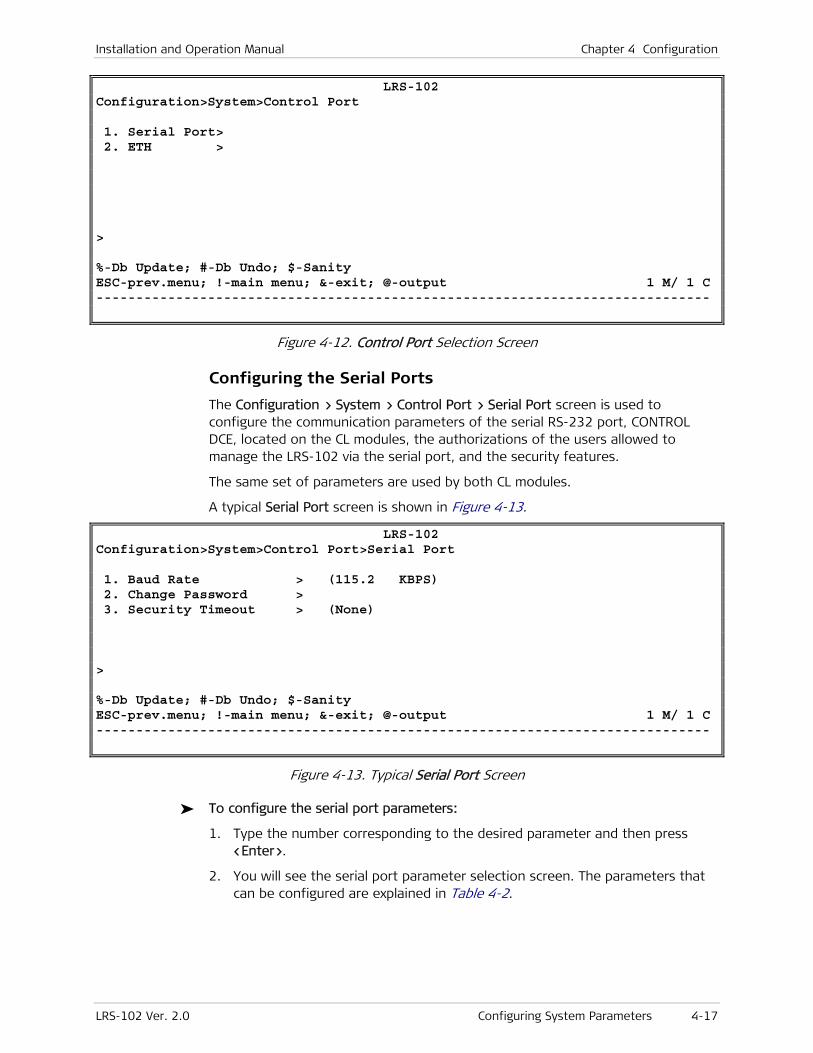
Installation and Operation Manual Chapter 4 Configuration
LRS-102 Ver. 2.0 Configuring System Parameters 4-17
LRS-102 Configuration>System>Control Port 1. Serial Port> 2. ETH > > %-Db Update; #-Db Undo; $-Sanity ESC-prev.menu; !-main menu; &-exit; @-output 1 M/ 1 C -----------------------------------------------------------------------------
Figure 4-12. Control Port Selection Screen
Configuring the Serial Ports
The Configuration > System > Control Port > Serial Port screen is used to configure the communication parameters of the serial RS-232 port, CONTROL DCE, located on the CL modules, the authorizations of the users allowed to manage the LRS-102 via the serial port, and the security features.
The same set of parameters are used by both CL modules.
A typical Serial Port screen is shown in Figure 4-13.
LRS-102 Configuration>System>Control Port>Serial Port 1. Baud Rate > (115.2 KBPS) 2. Change Password > 3. Security Timeout > (None) > %-Db Update; #-Db Undo; $-Sanity ESC-prev.menu; !-main menu; &-exit; @-output 1 M/ 1 C -----------------------------------------------------------------------------
Figure 4-13. Typical Serial Port Screen
To configure the serial port parameters:
1. Type the number corresponding to the desired parameter and then press <Enter>.
2. You will see the serial port parameter selection screen. The parameters that can be configured are explained in Table 4-2.
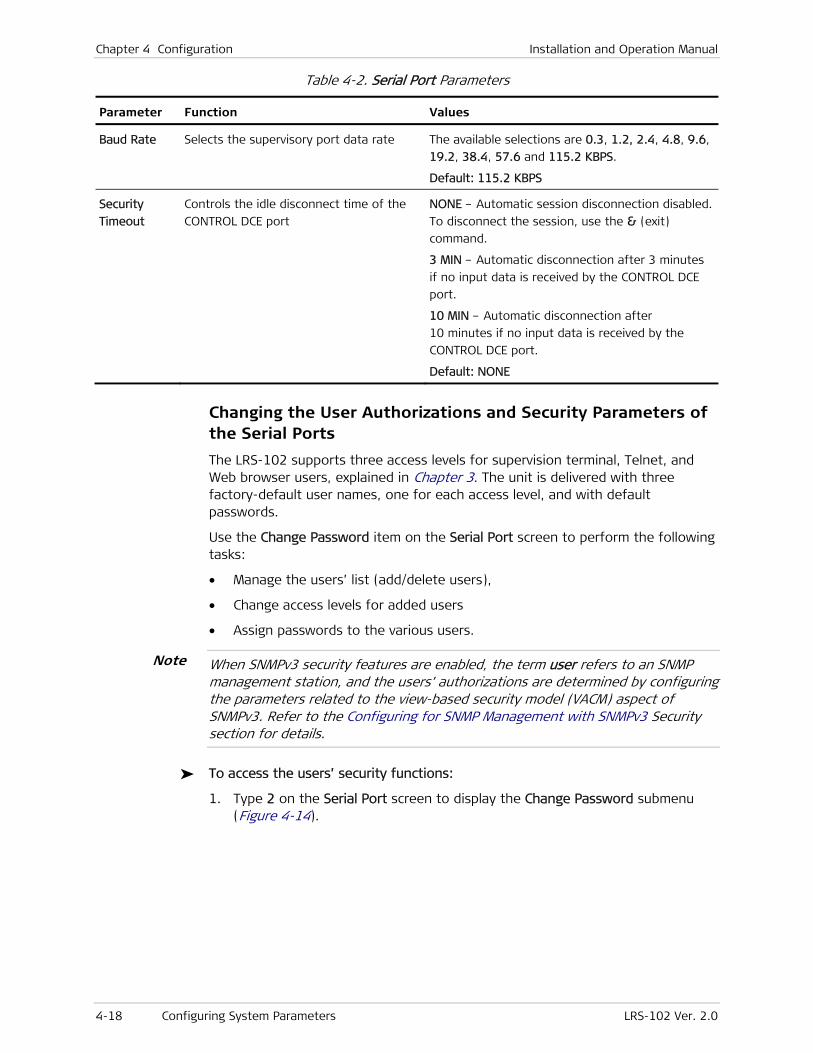
Chapter 4 Configuration Installation and Operation Manual
4-18 Configuring System Parameters LRS-102 Ver. 2.0
Table 4-2. Serial Port Parameters
Parameter Function Values
Baud Rate Selects the supervisory port data rate The available selections are 0.3, 1.2, 2.4, 4.8, 9.6,
19.2, 38.4, 57.6 and 115.2 KBPS.
Default: 115.2 KBPS
Security
Timeout
Controls the idle disconnect time of the
CONTROL DCE port
NONE – Automatic session disconnection disabled.
To disconnect the session, use the & (exit)
command.
3 MIN – Automatic disconnection after 3 minutes
if no input data is received by the CONTROL DCE
port.
10 MIN – Automatic disconnection after
10 minutes if no input data is received by the
CONTROL DCE port.
Default: NONE
Changing the User Authorizations and Security Parameters of the Serial Ports
The LRS-102 supports three access levels for supervision terminal, Telnet, and Web browser users, explained in Chapter 3. The unit is delivered with three factory-default user names, one for each access level, and with default passwords.
Use the Change Password item on the Serial Port screen to perform the following tasks:
• Manage the users’ list (add/delete users),
• Change access levels for added users
• Assign passwords to the various users.
When SNMPv3 security features are enabled, the term user refers to an SNMP management station, and the users’ authorizations are determined by configuring the parameters related to the view-based security model (VACM) aspect of SNMPv3. Refer to the Configuring for SNMP Management with SNMPv3 Security section for details.
To access the users’ security functions:
1. Type 2 on the Serial Port screen to display the Change Password submenu (Figure 4-14).
Note
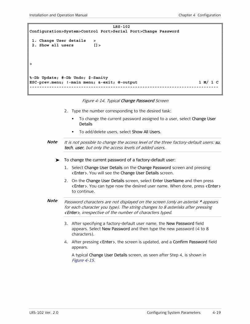
Installation and Operation Manual Chapter 4 Configuration
LRS-102 Ver. 2.0 Configuring System Parameters 4-19
LRS-102 Configuration>System>Control Port>Serial Port>Change Password 1. Change User details > 2. Show all users []> > %-Db Update; #-Db Undo; $-Sanity ESC-prev.menu; !-main menu; &-exit; @-output 1 M/ 1 C -----------------------------------------------------------------------------
Figure 4-14. Typical Change Password Screen
2. Type the number corresponding to the desired task:
To change the current password assigned to a user, select Change User Details
To add/delete users, select Show All Users.
It is not possible to change the access level of the three factory-default users: su, tech, user, but only the access levels of added users.
To change the current password of a factory-default user:
1. Select Change User Details on the Change Password screen and pressing <Enter>. You will see the Change User Details screen.
2. On the Change User Details screen, select Enter UserName and then press <Enter>. You can type now the desired user name. When done, press <Enter> to continue.
Password characters are not displayed on the screen (only an asterisk * appears for each character you type). The string changes to 8 asterisks after pressing <Enter>, irrespective of the number of characters typed.
3. After specifying a factory-default user name, the New Password field appears. Select New Password and then type the new password (4 to 8 characters).
4. After pressing <Enter>, the screen is updated, and a Confirm Password field appears.
A typical Change User Details screen, as seen after Step 4, is shown in Figure 4-15.
Note
Note

Chapter 4 Configuration Installation and Operation Manual
4-20 Configuring System Parameters LRS-102 Ver. 2.0
LRS-102 ...>System>Control Port>Serial Port>Change Password>Change User details Enter UserName (to change) ... (su) New Password ... (********) 1. Confirm Password ... (********) > %-Db Update; #-Db Undo; $-Sanity ESC-prev.menu; !-main menu; &-exit; @-output 1 M/ 1 C -----------------------------------------------------------------------------
Figure 4-15. Typical Change User Details Screen (Factory-Default User)
5. Select Confirm Password and then type the new password a second time for confirmation. Press <Enter> when done.
After confirming password, the following message appears: Password has been changed!! Update DB to finalize process!!
6. To activate the new password, type % to update the database and then confirm the action.
To change the current password of an added user:
1. Select Change User Details on the Change Password screen and pressing <Enter>. You will see the Change User Details screen.
2. On the Change User Details screen, select Enter UserName and then press <Enter>. Now you can type the desired user name. When done, press <Enter> to continue.
3. After specifying an added user name, the screen is updated to enable two actions:
Change the access level of the selected user
Change the password of the selected user. Skip to Step 4 if that is what you want to do.
To change the access level, select Access Level and then press <Enter>.
You will see a selection screen with four access levels (Figure 4-16). Note that the Operator level is not defined for LRS-102 (it has the same capabilities as the Monitor). See Chapter 3 for details on the capabilities of each access level.
At this stage, type the number corresponding to the desired level, and then press <Enter> to return to the screen of Figure 4-15.
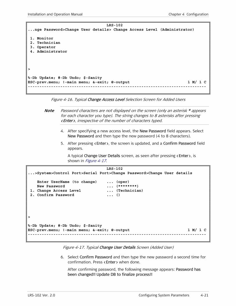
Installation and Operation Manual Chapter 4 Configuration
LRS-102 Ver. 2.0 Configuring System Parameters 4-21
LRS-102 ...nge Password>Change User details> Change Access Level (Administrator) 1. Monitor 2. Technician 3. Operator 4. Administrator > %-Db Update; #-Db Undo; $-Sanity ESC-prev.menu; !-main menu; &-exit; @-output 1 M/ 1 C -----------------------------------------------------------------------------
Figure 4-16. Typical Change Access Level Selection Screen for Added Users
Password characters are not displayed on the screen (only an asterisk * appears for each character you type). The string changes to 8 asterisks after pressing <Enter>, irrespective of the number of characters typed.
4. After specifying a new access level, the New Password field appears. Select New Password and then type the new password (4 to 8 characters).
5. After pressing <Enter>, the screen is updated, and a Confirm Password field appears.
A typical Change User Details screen, as seen after pressing <Enter>, is shown in Figure 4-17.
LRS-102 ...>System>Control Port>Serial Port>Change Password>Change User details Enter UserName (to change) ... (oper) New Password ... (********) 1. Change Access Level ... (Technician) 2. Confirm Password ... () > %-Db Update; #-Db Undo; $-Sanity ESC-prev.menu; !-main menu; &-exit; @-output 1 M/ 1 C -----------------------------------------------------------------------------
Figure 4-17. Typical Change User Details Screen (Added User)
6. Select Confirm Password and then type the new password a second time for confirmation. Press <Enter> when done.
After confirming password, the following message appears: Password has been changed!! Update DB to finalize process!!
Note
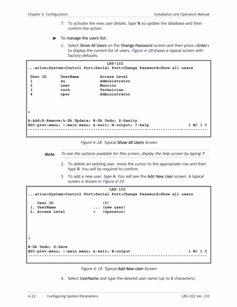
Chapter 4 Configuration Installation and Operation Manual
4-22 Configuring System Parameters LRS-102 Ver. 2.0
7. To activate the new user details, type % to update the database and then confirm the action.
To manage the users list:
1. Select Show All Users on the Change Password screen and then press <Enter> to display the current list of users. Figure 4-18 shows a typical screen with factory-defaults.
LRS-102 ...ation>System>Control Port>Serial Port>Change Password>Show all users User ID UserName Access Level 1 su Administrator 2 user Monitor 3 tech Technician 4 oper Administrator > A-Add;R-Remove;%-Db Update; #-Db Undo; $-Sanity ESC-prev.menu; !-main menu; &-exit; @-output; ?-help 1 M/ 1 C -----------------------------------------------------------------------------
Figure 4-18. Typical Show All Users Screen
To see the options available for this screen, display the help screen by typing ?.
2. To delete an existing user, move the cursor to the appropriate row and then type R. You will be required to confirm.
3. To add a new user, type A. You will see the Add New User screen. A typical screen is shown in Figure 4-19.
LRS-102 ...ation>System>Control Port>Serial Port>Change Password>Show all users User ID (5) 1. UserName ... (new user) 2. Access Level > (Operator) > #-Db Undo; S-Save ESC-prev.menu; !-main menu; &-exit; @-output 1 M/ 1 C -----------------------------------------------------------------------------
Figure 4-19. Typical Add New User Screen
4. Select UserName and type the desired user name (up to 8 characters).
Note
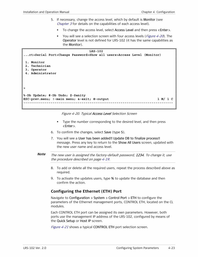
Installation and Operation Manual Chapter 4 Configuration
LRS-102 Ver. 2.0 Configuring System Parameters 4-23
5. If necessary, change the access level, which by default is Monitor (see Chapter 3 for details on the capabilities of each access level).
To change the access level, select Access Level and then press <Enter>.
You will see a selection screen with four access levels (Figure 4-20). The Operator level is not defined for LRS-102 (it has the same capabilities as the Monitor).
LRS-102 ...rt>Serial Port>Change Password>Show all users>Access Level (Monitor) 1. Monitor 2. Technician 3. Operator 4. Administrator > %-Db Update; #-Db Undo; $-Sanity ESC-prev.menu; !-main menu; &-exit; @-output 1 M/ 1 C -----------------------------------------------------------------------------
Figure 4-20. Typical Access Level Selection Screen
Type the number corresponding to the desired level, and then press <Enter>.
6. To confirm the changes, select Save (type S).
7. You will see a User has been added!! Update DB to finalize process!! message. Press any key to return to the Show All Users screen, updated with the new user name and access level.
The new user is assigned the factory-default password, 1234. To change it, use the procedure described on page 4-19.
8. To add or delete all the required users, repeat the process described above as required.
9. To activate the updates users, type % to update the database and then confirm the action.
Configuring the Ethernet (ETH) Port
Navigate to Configuration > System > Control Port > ETH to configure the parameters of the Ethernet management ports, CONTROL ETH, located on the CL modules.
Each CONTROL ETH port can be assigned its own parameters. However, both ports use the management IP address of the LRS-102, configured by means of the Quick Setup or Host IP screen.
Figure 4-21 shows a typical CONTROL ETH port selection screen.
Note

Chapter 4 Configuration Installation and Operation Manual
4-24 Configuring System Parameters LRS-102 Ver. 2.0
LRS-102 Configuration>System>Control Port>ETH 1. CL-A> 2. CL-B> > %-Db Update; #-Db Undo; $-Sanity ESC-prev.menu; !-main menu; &-exit; @-output 1 M/ 1 C -----------------------------------------------------------------------------
Figure 4-21. Typical CONTROL ETH Port Selection Screen
To select the CONTROL ETH port to be configured:
1. Select the port on the ETH screen, and then press <Enter>. You will see the port configuration screen. A typical screen is shown in Figure 4-22.
` LRS-102 Configuration>System>Control Port>ETH>CL-A 1. Admin Status > (Up) 2. Name ... () > %-Db Update; #-Db Undo; $-Sanity ESC-prev.menu; !-main menu; &-exit; @-output 1 M/ 1 C -----------------------------------------------------------------------------
Figure 4-22. Typical CONTROL ETH Configuration Screen
To define the CONTROL ETH port parameters:
1. Select the number of the desired parameter and then press <Enter>. The parameters are explained in Table 4-3.
Table 4-3. CONTROL ETH Port Configuration Parameters
Parameter Function Values
Admin Status Used to enable/disable the flow
of management traffic through
the selected Ethernet port
DOWN – The flow of management traffic is disabled. This
state should be selected as long as the configuration of
the corresponding port has not yet been completed, or
when it is necessary to stop traffic flow through the port.
UP – The flow of management traffic is enabled.
Default: UP
Name Used to enter a logical name for
the selected CONTROL ETH port
Up to 10 characters.
Default: Empty string
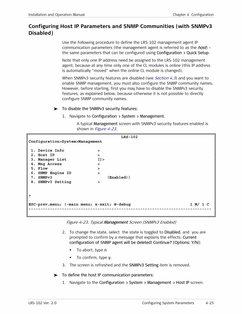
Installation and Operation Manual Chapter 4 Configuration
LRS-102 Ver. 2.0 Configuring System Parameters 4-25
Configuring Host IP Parameters and SNMP Communities (with SNMPv3 Disabled)
Use the following procedure to define the LRS-102 management agent IP communication parameters (the management agent is referred to as the host) – the same parameters that can be configured using Configuration > Quick Setup.
Note that only one IP address need be assigned to the LRS-102 management agent, because at any time only one of the CL modules is online (this IP address is automatically “moved” when the online CL module is changed).
When SNMPv3 security features are disabled (see Section 4.3) and you want to enable SNMP management, you must also configure the SNMP community names. However, before starting, first you may have to disable the SNMPv3 security features, as explained below, because otherwise it is not possible to directly configure SNMP community names.
To disable the SNMPv3 security features:
1. Navigate to Configuration > System > Management.
A typical Management screen with SNMPv3 security features enabled is shown in Figure 4-23.
LRS-102 Configuration>System>Management 1. Device Info > 2. Host IP > 3. Manager List []> 4. Mng Access > 5. Flow > 6. SNMP Engine ID > 7. SNMPv3 (Enabled)) 8. SNMPv3 Setting > > ESC-prev.menu; !-main menu; &-exit; @-debug 1 M/ 1 C -----------------------------------------------------------------------------
Figure 4-23. Typical Management Screen (SNMPv3 Enabled)
2. To change the state, select the state is toggled to Disabled, and you are prompted to confirm by a message that explains the effects: Current configuration of SNMP agent will be deleted! Continue? (Options: Y/N):
To abort, type n
To confirm, type y.
3. The screen is refreshed and the SNMPv3 Setting item is removed.
To define the host IP communication parameters:
1. Navigate to the Configuration > System > Management > Host IP screen.
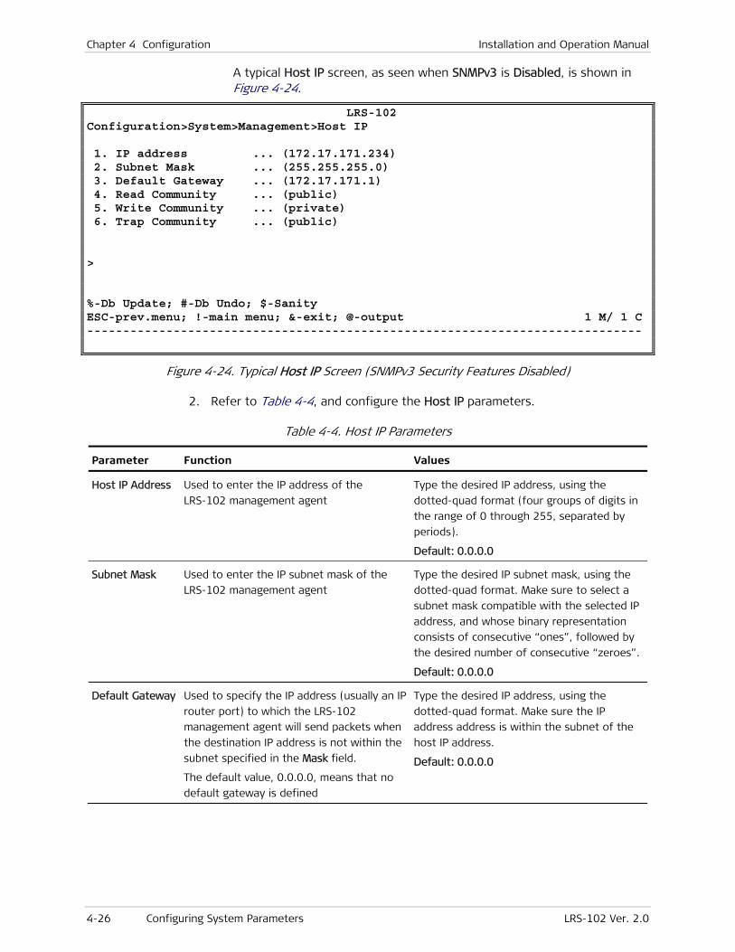
Chapter 4 Configuration Installation and Operation Manual
4-26 Configuring System Parameters LRS-102 Ver. 2.0
A typical Host IP screen, as seen when SNMPv3 is Disabled, is shown in Figure 4-24.
LRS-102 Configuration>System>Management>Host IP 1. IP address ... (172.17.171.234) 2. Subnet Mask ... (255.255.255.0) 3. Default Gateway ... (172.17.171.1) 4. Read Community ... (public) 5. Write Community ... (private) 6. Trap Community ... (public) > %-Db Update; #-Db Undo; $-Sanity ESC-prev.menu; !-main menu; &-exit; @-output 1 M/ 1 C -----------------------------------------------------------------------------
Figure 4-24. Typical Host IP Screen (SNMPv3 Security Features Disabled)
2. Refer to Table 4-4, and configure the Host IP parameters.
Table 4-4. Host IP Parameters
Parameter Function Values
Host IP Address Used to enter the IP address of the
LRS-102 management agent
Type the desired IP address, using the
dotted-quad format (four groups of digits in
the range of 0 through 255, separated by
periods).
Default: 0.0.0.0
Subnet Mask Used to enter the IP subnet mask of the
LRS-102 management agent
Type the desired IP subnet mask, using the
dotted-quad format. Make sure to select a
subnet mask compatible with the selected IP
address, and whose binary representation
consists of consecutive “ones”, followed by
the desired number of consecutive “zeroes”.
Default: 0.0.0.0
Default Gateway Used to specify the IP address (usually an IP
router port) to which the LRS-102
management agent will send packets when
the destination IP address is not within the
subnet specified in the Mask field.
The default value, 0.0.0.0, means that no
default gateway is defined
Type the desired IP address, using the
dotted-quad format. Make sure the IP
address address is within the subnet of the
host IP address.
Default: 0.0.0.0

Installation and Operation Manual Chapter 4 Configuration
LRS-102 Ver. 2.0 Configuring System Parameters 4-27
Parameter Function Values
Read Enter here the read-only SNMP community
name to be accepted by the LRS-102
management agent.
SNMP-based management stations using
this community will not be able to modify
the LRS-102 configuration, nor initiate
diagnostic activities.
This parameter is displayed only when
SNMPv3 is Disabled
Enter the desired alphanumeric string (pay
attention to case).
Default: public
Write Enter here the read-and-write SNMP
community name to be accepted by the
LRS-102 management agent.
Use this community for SNMP-based
management stations that must be able to
perform all the activities.
This parameter is displayed only when
SNMPv3 is Disabled
Enter the desired alphanumeric string (pay
attention to case).
Default: private
Trap Enter here the SNMP community name that
will be specified by the LRS-102
management agent in the traps sent to
SNMP-based management stations.
This parameter is displayed only when
SNMPv3 is Disabled
Enter the desired alphanumeric string (pay
attention to case).
Default: public
Configuring Management Access
Use the following procedure to control globally the access to the LRS-102 management agent using Telnet, SNMP management stations, and/or Web browsers. This procedure enables to block the desired access options at the LRS-102 level, overriding the access rights of any user that may be logged on the LRS-102.
The supervisory terminal can always be used to access the LRS-102 management agent.
To navigate to the required screen, use Configuration > System > Management > Mng Access.
A typical Mng Access screen is shown in Figure 4-25.
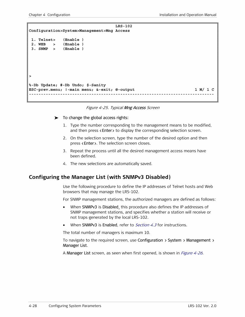
Chapter 4 Configuration Installation and Operation Manual
4-28 Configuring System Parameters LRS-102 Ver. 2.0
LRS-102 Configuration>System>Management>Mng Access 1. Telnet> (Enable ) 2. WEB > (Enable ) 3. SNMP > (Enable ) > %-Db Update; #-Db Undo; $-Sanity ESC-prev.menu; !-main menu; &-exit; @-output 1 M/ 1 C -----------------------------------------------------------------------------
Figure 4-25. Typical Mng Access Screen
To change the global access rights:
1. Type the number corresponding to the management means to be modified, and then press <Enter> to display the corresponding selection screen.
2. On the selection screen, type the number of the desired option and then press <Enter>. The selection screen closes.
3. Repeat the process until all the desired management access means have been defined.
4. The new selections are automatically saved.
Configuring the Manager List (with SNMPv3 Disabled)
Use the following procedure to define the IP addresses of Telnet hosts and Web browsers that may manage the LRS-102.
For SNMP management stations, the authorized managers are defined as follows:
• When SNMPv3 is Disabled¸ this procedure also defines the IP addresses of SNMP management stations, and specifies whether a station will receive or not traps generated by the local LRS-102.
• When SNMPv3 is Enabled, refer to Section 4.3 for instructions.
The total number of managers is maximum 10.
To navigate to the required screen, use Configuration > System > Management > Manager List.
A Manager List screen, as seen when first opened, is shown in Figure 4-26.
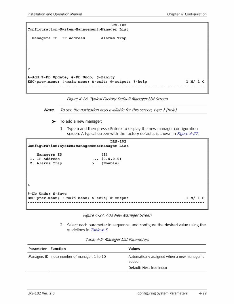
Installation and Operation Manual Chapter 4 Configuration
LRS-102 Ver. 2.0 Configuring System Parameters 4-29
LRS-102 Configuration>System>Management>Manager List Managers ID IP Address Alarms Trap > A-Add;%-Db Update; #-Db Undo; $-Sanity ESC-prev.menu; !-main menu; &-exit; @-output; ?-help 1 M/ 1 C -----------------------------------------------------------------------------
Figure 4-26. Typical Factory-Default Manager List Screen
To see the navigation keys available for this screen, type ? (help).
To add a new manager:
1. Type a and then press <Enter> to display the new manager configuration screen. A typical screen with the factory defaults is shown in Figure 4-27.
LRS-102 Configuration>System>Management>Manager List Managers ID (1) 1. IP Address ... (0.0.0.0) 2. Alarms Trap > (Enable) > #-Db Undo; S-Save ESC-prev.menu; !-main menu; &-exit; @-output 1 M/ 1 C -----------------------------------------------------------------------------
Figure 4-27. Add New Manager Screen
2. Select each parameter in sequence, and configure the desired value using the guidelines in Table 4-5.
Table 4-5. Manager List Parameters
Parameter Function Values
Managers ID Index number of manager, 1 to 10 Automatically assigned when a new manager is
added.
Default: Next free index
Note
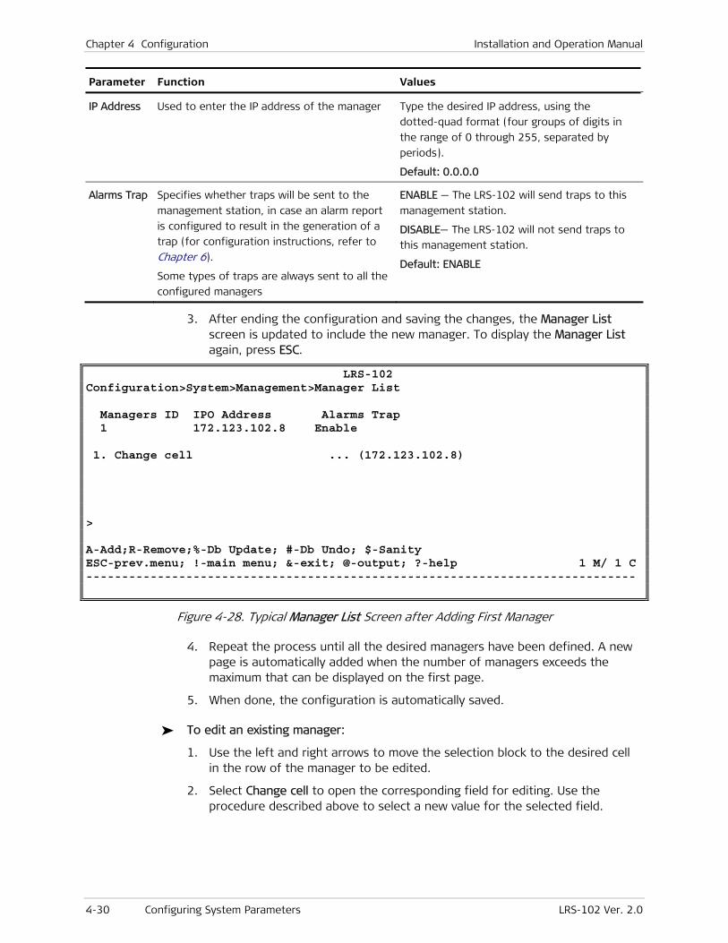
Chapter 4 Configuration Installation and Operation Manual
4-30 Configuring System Parameters LRS-102 Ver. 2.0
Parameter Function Values
IP Address Used to enter the IP address of the manager Type the desired IP address, using the
dotted-quad format (four groups of digits in
the range of 0 through 255, separated by
periods).
Default: 0.0.0.0
Alarms Trap Specifies whether traps will be sent to the
management station, in case an alarm report
is configured to result in the generation of a
trap (for configuration instructions, refer to
Chapter 6).
Some types of traps are always sent to all the
configured managers
ENABLE — The LRS-102 will send traps to this
management station.
DISABLE— The LRS-102 will not send traps to
this management station.
Default: ENABLE
3. After ending the configuration and saving the changes, the Manager List screen is updated to include the new manager. To display the Manager List again, press ESC.
LRS-102 Configuration>System>Management>Manager List Managers ID IPO Address Alarms Trap 1 172.123.102.8 Enable 1. Change cell ... (172.123.102.8) > A-Add;R-Remove;%-Db Update; #-Db Undo; $-Sanity ESC-prev.menu; !-main menu; &-exit; @-output; ?-help 1 M/ 1 C -----------------------------------------------------------------------------
Figure 4-28. Typical Manager List Screen after Adding First Manager
4. Repeat the process until all the desired managers have been defined. A new page is automatically added when the number of managers exceeds the maximum that can be displayed on the first page.
5. When done, the configuration is automatically saved.
To edit an existing manager:
1. Use the left and right arrows to move the selection block to the desired cell in the row of the manager to be edited.
2. Select Change cell to open the corresponding field for editing. Use the procedure described above to select a new value for the selected field.
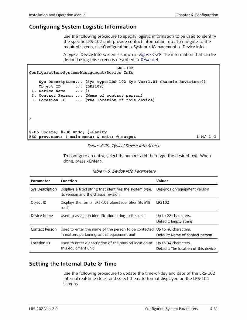
Installation and Operation Manual Chapter 4 Configuration
LRS-102 Ver. 2.0 Configuring System Parameters 4-31
Configuring System Logistic Information
Use the following procedure to specify logistic information to be used to identify the specific LRS-102 unit, provide contact information, etc. To navigate to the required screen, use Configuration > System > Management > Device Info.
A typical Device Info screen is shown in Figure 4-29. The information that can be defined using this screen is described in Table 4-6.
LRS-102 Configuration>System>Management>Device Info Sys Description... (Sys type:LRS-102 Sys Ver:1.01 Chassis Revision:0) Object ID ... (LRS102) 1. Device Name ... () 2. Contact Person ... (Name of contact person) 3. Location ID ... (The location of this device) > %-Db Update; #-Db Undo; $-Sanity ESC-prev.menu; !-main menu; &-exit; @-output 1 M/ 1 C
Figure 4-29. Typical Device Info Screen
To configure an entry, select its number and then type the desired text. When done, press <Enter>.
Table 4-6. Device Info Parameters
Parameter Function Values
Sys Description Displays a fixed string that identifies the system type,
its version and the chassis revision
Depends on equipment version
Object ID Displays the formal LRS-102 object identifier (its MIB
root)
LRS102
Device Name Used to assign an identification string to this unit Up to 22 characters.
Default: Empty string
Contact Person Used to enter the name of the person to be contacted
in matters pertaining to this equipment unit
Up to 46 characters.
Default: Name of contact person
Location ID Used to enter a description of the physical location of
this equipment unit
Up to 34 characters.
Default: The location of this device
Setting the Internal Date & Time
Use the following procedure to update the time-of-day and date of the LRS-102 internal real-time clock, and select the date format displayed on the LRS-102 screens.
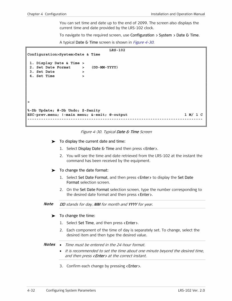
Chapter 4 Configuration Installation and Operation Manual
4-32 Configuring System Parameters LRS-102 Ver. 2.0
You can set time and date up to the end of 2099. The screen also displays the current time and date provided by the LRS-102 clock.
To navigate to the required screen, use Configuration > System > Date & Time.
A typical Date & Time screen is shown in Figure 4-30.
LRS-102 Configuration>System>Date & Time 1. Display Date & Time > 2. Set Date Format > (DD-MM-YYYY) 3. Set Date > 4. Set Time > > %-Db Update; #-Db Undo; $-Sanity ESC-prev.menu; !-main menu; &-exit; @-output 1 M/ 1 C -----------------------------------------------------------------------------
Figure 4-30. Typical Date & Time Screen
To display the current date and time:
1. Select Display Date & Time and then press <Enter>.
2. You will see the time and date retrieved from the LRS-102 at the instant the command has been received by the equipment.
To change the date format:
1. Select Set Date Format, and then press <Enter> to display the Set Date Format selection screen.
2. On the Set Date Format selection screen, type the number corresponding to the desired date format and then press <Enter>.
DD stands for day, MM for month and YYYY for year.
To change the time:
1. Select Set Time, and then press <Enter>.
2. Each component of the time of day is separately set. To change, select the desired item and then type the desired value.
• Time must be entered in the 24-hour format.
• It is recommended to set the time about one minute beyond the desired time, and then press <Enter> at the correct instant.
3. Confirm each change by pressing <Enter>.
Note
Notes
Installation and Operation Manual Chapter 4 Configuration
LRS-102 Ver. 2.0 Configuring LRS-102 for SNMPv3 Management 4-33
To change the date:
1. Select Set Date, and then press <Enter>.
2. Each component of the time of day is separately set. To change, select the desired item and then type the desired value.
3. Confirm each change by pressing <Enter>.
4.3 Configuring LRS-102 for SNMPv3 Management
This section presents the main SNMPv3 capabilities, and explains the following procedures:
• How to enable the SNMPv3 security features
• How to configure LRS-102 for management with SNMPv3 security features.
• How to configure LRS-102 for compatibility with management stations that cannot use the SNMPv3 security features, to ensure compatibility with SNMP support in previous LRS-102 software and management station versions. This is performed by mapping SNMPv1 settings to SNMPv3 settings.
You can find below a concise description of the main SNMPv3 capabilities applicable to LRS-102, and descriptions of terms related to the SNMPv3 configuration parameters of LRS-102.
Overview of SNMPv3 Capabilities
The basic SNMP protocol (SNMP version 1, or SNMPv1) can neither authenticate the source of a management message, nor provide privacy (encryption). The SNMP version 2 of the protocol (SNMPv2) adds some functional improvements and extensions to SNMPv1, but does not address security problems.
To overcome the security shortcomings of SNMPv1 and SNMPv2, LRS-102 can be configured to use the security features of SNMP protocol version 3 (SNMPv3).
SNMPv3 provides a security framework for SNMPv1 and SNMPv2 that adds the following main capabilities:
• Authentication – checks the integrity of management data, and also verifies its origin to ensure that unauthorized users will not masquerade as authorized users
• Privacy – ensures that unauthorized users cannot monitor the management information passing between managed systems and management stations
• Authorization and access control – ensures that only authorized users can perform SNMP network management functions and contact the managed systems.
To support these additional capabilities, SNMPv3 also includes specific administrative features, such as naming, security policies, user and key management, and selectable notification capabilities.
Chapter 4 Configuration Installation and Operation Manual
4-34 Configuring LRS-102 for SNMPv3 Management LRS-102 Ver. 2.0
Key management requires the using organization to implement an appropriate key distribution method, which is beyond the scope of SNMPv3, and therefore is also not covered in this manual. It is the responsibility of the using organization to maintain appropriate key management and distribution channels.
User-Based Security Model (USM)
SNMPv3 authentication and privacy services are provided by means of the User-Based Security Model (USM), defined in RFC2272. Proper use of USM protects against modification of information in transit from an authorized entity (including modification of message order, delaying or replaying of valid messages to change their effect, etc.), prevents an unauthorized entity from performing management operations by assuming the identity of an authorized entity, and prevents disclosure of the contents of the messages exchanged between a management station and an agent.
To achieve these goals, USM uses authentication to check the integrity of transmitted messages, and encryption to prevent disclosure:
• Authentication mechanisms. Mechanisms that provide integrity checks based on a secret key are usually called message authentication codes (MAC). Typically, message authentication codes are used between two parties that share a secret key in order to validate the information transmitted between these parties. Therefore, an SNMP engine requires an authentication key and a privacy key (actually, for each management session, a set of one-time session keys are generated). Separate values of these two keys are maintained for each local and remote user, and their values must be stored by each user, because the keys are not accessible via SNMP.
USM authentication protocol is based on the key-Hashing Message Authentication Code (HMAC), described in RFC2104. HMAC uses a user-selected secure hash function and a secret key to produce a message authentication code. USM allows the use of one of two alternative authentication protocols, where both generate a 96-bit output that is used to check message integrity:
HMAC-MD5-96: HMAC is used with MD5 (Message Digest algorithm 5) as the underlying hash function.
HMAC-SHA-96: HMAC is used with SHA-1 (Secure Hashing Algorithm 1).
• Encryption mechanism. USM uses the cipher block chaining (CBC) mode of the Data Encryption Standard (DES) for encryption, with a key length of 56 bits.
SNMP Security Levels
The USM capabilities enable the user to select the level of security at which SNMP messages can be sent or with which operations are being processed. The available options are as follows:
• No authentication and no privacy (encryption) – the lowest protection.
• With authentication, but without privacy
• With authentication and with privacy – the best protection level.
Note
Installation and Operation Manual Chapter 4 Configuration
LRS-102 Ver. 2.0 Configuring LRS-102 for SNMPv3 Management 4-35
SNMPv3 Administrative Features
The administrative features of SNMPv3 enable determining the entities that are allowed to manage an entity, for example, the LRS-102. There are two administrative aspects:
• User management. During SNMPv3 configuration, it is necessary to define allowed users and their security attributes. For each user, it is possible to select the security level, and the passwords used for each type of protection (authentication and/or privacy) needed at the selected level.
• Target and notification management. As part of the SNMPv3 configuration, you can also define the notification capabilities for a list of entities referred to as targets (of notification messages). For each target, you can specify a message processing model, a security model, and the required security level. You can also define a list of notifications that can be sent to the corresponding target.
LRS-102 supports only the sending of traps for notification purposes.
View-Based Access Control Model (VACM)
SNMP manager authorizations are defined by means of the view-based access security model (the name of the model is derived from the method used to define the authorizations: control over the MIB parts that can be viewed by each manager).
VACM makes it possible to configure each SNMPv3 agent to allow different levels of access to different managers: for example, the LRS-102 SNMPv3 agent may restrict some managers to view only the LRS-102 performance statistics, and allow others to view and update LRS-102 configuration parameters. Moreover, the SNMPv3 agent can also limit what a manager can do by accepting only commands that invoke parameters included in certain parts of the relevant MIBs (for example, read-only access to the configuration parameters part of a MIB, and read-write access to the diagnostics part).
The access control policy used by the agent for each manager must be preconfigured (the policy essentially consists of a table that details the access privileges of each authorized manager). For LRS-102, the configuration of the VACM parameters can only be made by means of a MIB browser, and/or by SNMP commands.
RAD also offers a dedicated SNMPv3 Manager utility to help you edit parameters not covered by the supervision terminal screens. For additional information, contact RAD Technical Support.
Configuring SNMP Engine ID
The SNMP engine ID is a parameter defined in relation with SNMPv3, whose primary function is to provide a unique and unambiguous identifier of the local SNMP engine (processor), which is part of the LRS-102 management subsystem. Thus, it thus also identifies the local LRS-102.
Note
Note

Chapter 4 Configuration Installation and Operation Manual
4-36 Configuring LRS-102 for SNMPv3 Management LRS-102 Ver. 2.0
SNMPv3 bases the generation of its authentication and privacy session keys on several parameters, one of them being the SNMP engine ID. Therefore, the SNMP engine ID must always be configured before configuring any other SNMPv3 parameters, and in particular – before configuring users (if you change the SNMP engine ID, you must also reconfigure the users). Thus, you can configure the SNMP engine ID even when SNMPv3 support is disabled.
The SNMP engine ID is a string that has three components:
• An automatically-generated, fixed part
• A part that identifies the configuration type (method) used to derive the user-defined part is selectable. The standards define three methods:
IPv4 –The user-defined part is based on the host IP address. This ensures that the user-defined part is unique within the SNMP-managed network.
MAC Address –The user-defined part is based on the host MAC address. This option also ensures that the user-defined part is unique.
Text – The user-defined part is entered as a text string, which must comprise 4 to 27 alphanumeric characters. This is the standard method for LRS-102.
• A user-defined part, which must be unique within the SNMP-managed network.
To specify the SNMPv3 Engine ID:
1. Navigate to Configuration > System > Management.
2. Select SNMPv3 Engine ID.
A typical SNMP Engine ID screen, as seen when using the text configuration type, is shown in Figure 4-31. The current SNMP engine ID string appears in the Engine ID field.
3. To change the user-defined part,select Remaining Bytes, and then type the prescribed string, which must contain 4 to 27 alphanumeric characters.
4. When done, press <Enter> to confirm. The string is added to the Engine ID field (if the string is too long for the available display space, it is truncated, in which case the last digits are replaced by an ellipsis …):
5. After making changes on the SNMP Engine ID screen, a new item, S – Save, is added: to activate the new engine ID, type s.

Installation and Operation Manual Chapter 4 Configuration
LRS-102 Ver. 2.0 Configuring LRS-102 for SNMPv3 Management 4-37
LRS-102 Configuration>System>Management>SNMP Engine ID Engine ID ... (800000a40400000000 ) Engine ID Config Type > (Text) 1. Remaining Bytes ... () > Please select item <1 to 1> ESC-prev.menu; !-main menu; &-exit; @-debug 1 M/ 1 C -----------------------------------------------------------------------------
Figure 4-31. Typical SNMP Engine ID Screen
Enabling/Disabling SNMPv3 Security Features
When starting the SNMP configuration activities, the first action is to select whether to enable or disable the SNMPv3 security features: this action effects all the other SNMP parameters except SNMP Engine ID.
When changing the SNMPv3 mode, all the SNMPv3 settings are erased, and the factory defaults are restored. As explained in the Configuring Authorized User Security Parameters section, starting from the factory defaults will enable preparing a new set of SNMPv3 settings in accordance with your specific application requirements.
To enable configuring the SNMPv3 parameters, you must enable SNMPv3.
To enable the SNMPv3 security features:
1. Navigate to Configuration > System > Management.
A typical Management screen with SNMPv3 security features disabled (the factory default state) is shown in Figure 4-32.
LRS-102 Configuration>System>Management 1. Device Info > 2. Host IP > 3. Manager List []> 4. Mng Access > 5. Flow > 6. SNMP Engine ID > 7. SNMPv3 (Disabled)) > ESC-prev.menu; !-main menu; &-exit; @-debug 1 M/ 1 C -----------------------------------------------------------------------------
Figure 4-32. Typical Management Submenu (SNMPv3 Disabled)
Chapter 4 Configuration Installation and Operation Manual
4-38 Configuring LRS-102 for SNMPv3 Management LRS-102 Ver. 2.0
2. To change the state, select SNMPv3: you are prompted to confirm by a message that explains the effects: Current configuration of SNMP agent will be deleted! Continue? (Options: Y/N):
To abort, type n
To confirm, type y.
3. After typing y, the SNMPv3 state is toggled to Enabled, and a S – Save item is added.
4. To activate the selection, type s. The screen is refreshed and the SNMPv3 Setting item, used to access the SNMPv3 configuration tasks (see the Configuring for SNMP Management with SNMPv3 Security section) is added.
The same sequence is used to disable SNMPv3 (see also the Configuring Host IP Parameters and SNMP Communities (with SNMPv3 Disabled) section).
Configuring for SNMP Management with SNMPv3 Security Features
SNMPv3 Configuration Sequence
Before starting, make sure to configure the SNMP engine ID and enable SNMPv3 as explained above.
The SNMPv3 configuration sequence is as follows:
1. Configure security attributes for the prescribed users (management stations).
2. Add the prescribed notification tags.
3. Assign traps to each notification tag, to create a tag list.
4. Specify for each target its IP address, define its parameter set, and assign notification tags.
5. Add target (management stations) parameters.
With SNMPv3, the managers configured by means of the Manager List screen (see the Configuring the Manager List (with SNMPv3 Disabled) section) are no longer relevant: only the configured targets are managers.
However, to enable synchronizing the managers configured in the Manager List table with SNMPv3 managers, all the IP addresses configured in the Manager List table are automatically added to the target list when SNMPv3 is enabled (they can be seen in the Summary Target Table – see the Viewing the Summary Target Table section), but they are not active until their security and management parameters are defined.
The SNMPv3 parameters are configured by means of the SNMPv3 Setting submenu. A typical submenu is shown Figure 4-33. The parameters displayed on the submenu and the tasks that can be initiated are explained in Table 4-7.
Note
Note
Note
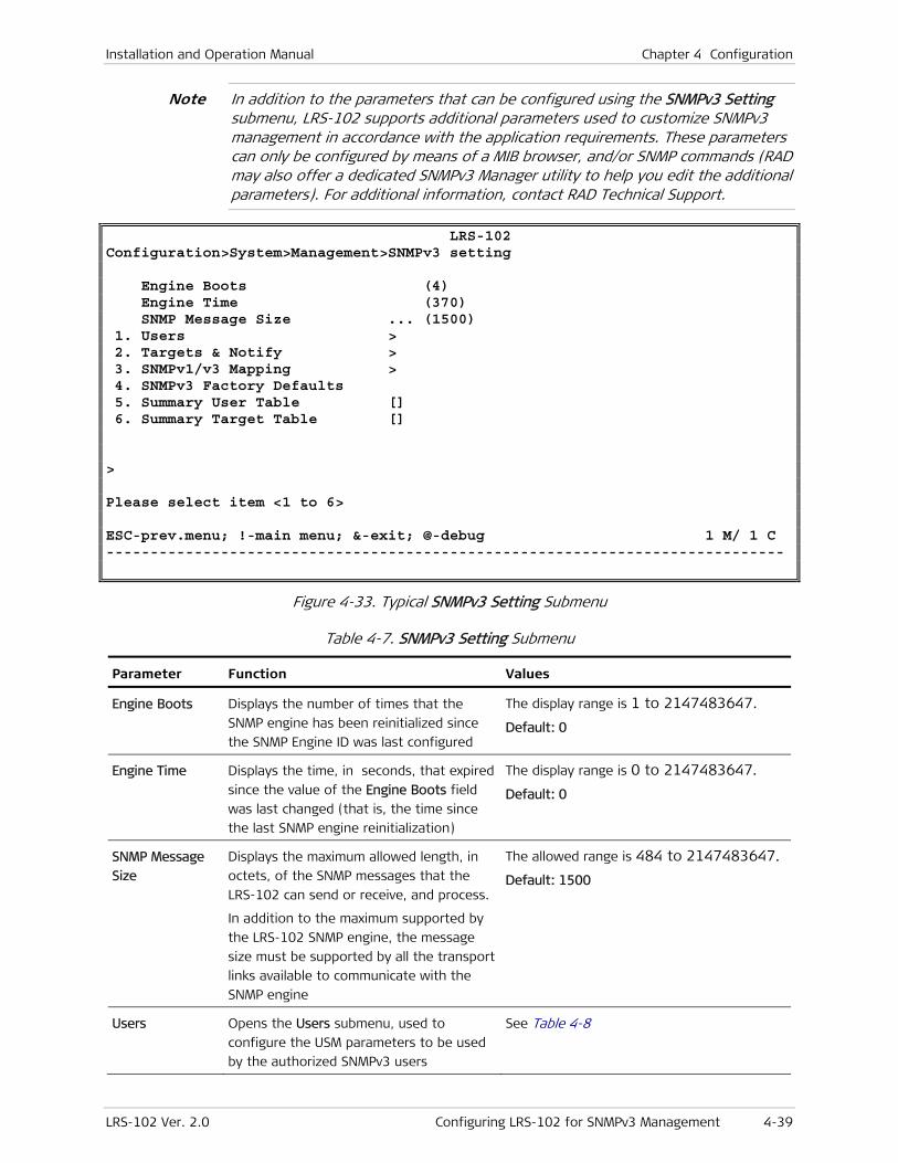
Installation and Operation Manual Chapter 4 Configuration
LRS-102 Ver. 2.0 Configuring LRS-102 for SNMPv3 Management 4-39
In addition to the parameters that can be configured using the SNMPv3 Setting submenu, LRS-102 supports additional parameters used to customize SNMPv3 management in accordance with the application requirements. These parameters can only be configured by means of a MIB browser, and/or SNMP commands (RAD may also offer a dedicated SNMPv3 Manager utility to help you edit the additional parameters). For additional information, contact RAD Technical Support.
LRS-102 Configuration>System>Management>SNMPv3 setting Engine Boots (4) Engine Time (370) SNMP Message Size ... (1500) 1. Users > 2. Targets & Notify > 3. SNMPv1/v3 Mapping > 4. SNMPv3 Factory Defaults 5. Summary User Table [] 6. Summary Target Table [] > Please select item <1 to 6> ESC-prev.menu; !-main menu; &-exit; @-debug 1 M/ 1 C -----------------------------------------------------------------------------
Figure 4-33. Typical SNMPv3 Setting Submenu
Table 4-7. SNMPv3 Setting Submenu
Parameter Function Values
Engine Boots Displays the number of times that the
SNMP engine has been reinitialized since
the SNMP Engine ID was last configured
The display range is 1 to 2147483647.
Default: 0
Engine Time Displays the time, in seconds, that expired
since the value of the Engine Boots field
was last changed (that is, the time since
the last SNMP engine reinitialization)
The display range is 0 to 2147483647.
Default: 0
SNMP Message
Size
Displays the maximum allowed length, in
octets, of the SNMP messages that the
LRS-102 can send or receive, and process.
In addition to the maximum supported by
the LRS-102 SNMP engine, the message
size must be supported by all the transport
links available to communicate with the
SNMP engine
The allowed range is 484 to 2147483647.
Default: 1500
Users Opens the Users submenu, used to
configure the USM parameters to be used
by the authorized SNMPv3 users
See Table 4-8
Note

Chapter 4 Configuration Installation and Operation Manual
4-40 Configuring LRS-102 for SNMPv3 Management LRS-102 Ver. 2.0
Parameter Function Values
Targets & Notify Opens the Targets & Notify submenu, used
to configure the parameters of the targets
(management stations that can manage
the LRS-102), and configure notifications
of LRS-102 events
See Table 4-9 to Table 4-12
SNMPv1/v3
Mapping
Opens the SNMPv1/v3 Mapping submenu,
used to configure the mapping of SNMPv1
security parameters to SNMPv3
parameters, to enable the LRS-102 to
support all the SNMP versions
See Table 4-12
SNMPv3 Factory
Defaults
Used to reload the SNMPv3 factory default
parameters.
This is useful for erasing the existing
configuration parameters and restoring the
SNMP engine to a known state.
In particular, this function is needed to
recover from configuration errors that may
prevent SNMP management
To restore defaults, select SNMPv3 Factory
Defaults, and then confirm the action
Summary User
Table
Displays information on the existing users
and their main configuration data
See the Viewing the Summary User Table section
Summary Target
Table
Displays information on the existing
targets, and their main configuration data
See the Viewing the Summary Target Table section
Configuring Authorized User Security Parameters
LRS-102 supports up to ten SNMPv3 managers, each having independently-configurable authorizations and security attributes. The security attributes needed by the USM to protect the SNMP traffic between LRS-102 and the prescribed managers are configured by means of Users screen.
LRS-102 has a single factory-default user, designated by the security name initial, which is configured for non-secure operations (that is, no authentication and no privacy). Non-secure operations are essential as a starting point for preliminary configuration, but additional users with appropriate authorizations and security attributes must be configured as soon as possible, to avoid defeating the very purpose of SNMPv3.
When several users are already defined, you can scroll the Security Name names by typing f (forward) or b (backward). Always remove a user when you must change its security parameters, and then define a new user with the desired parameters.
You can view the existing users, and their authorizations and security attributes by selecting Summary User Table, as explained in the Viewing the Summary User Table section.
User access control policies are defined via the vacmSecurityToGroupTable and vacmAccessTable tables, which can be accessed only as explained in the Note on page 4-39.
Note

Installation and Operation Manual Chapter 4 Configuration
LRS-102 Ver. 2.0 Configuring LRS-102 for SNMPv3 Management 4-41
To configure USM parameters for new users:
1. Navigate to Configuration > System > Management > SNMPv3 Setting > Users.
A typical SNMPv3 Setting screen with the factory-default user parameters is shown in Figure 4-34. The user configuration parameters are explained in Table 4-8.
LRS-102 Configuration>System>Management>SNMPv3 setting>Users 1. Security Name ... (initial) 2. Authentication Protocol > (usmNoAuthProtocol) > F - Forward; B - Backward; R - Remove ESC-prev.menu; !-main menu; &-exit; @-debug 1 M/ 1 C -----------------------------------------------------------------------------
Figure 4-34. Typical Factory-Default Users Screen
2. To add a new user, select Security Name and then type the desired user name, to replace the displayed user name.
3. Select Authentication Protocol, and then select one of the options listed in Table 4-8.
4. Additional fields, explained in Table 4-8, are displayed automatically after you make selections (and press <Enter> to confirm) for the Authentication Protocol and Privacy Protocol. Figure 4-35 shows a typical new user configuration screen, as seen after making all the necessary selections.
LRS-102 Configuration>System>Management>SNMPv3 setting>Users 1. Security Name ... (User1) 2. Authentication Protocol > (usmHMACMD5AuthProtocol) 3. Privacy Protocol > (usmDESPrivProtocol) 4. Authentication Password ... 5. Privacy Password ... > F - Forward; B - Backward; R - Remove ESC-prev.menu; !-main menu; &-exit; @-debug 1 M/ 1 C ----------------------------------------------------------------------------
Figure 4-35. Typical Users Screen for New User
Chapter 4 Configuration Installation and Operation Manual
4-42 Configuring LRS-102 for SNMPv3 Management LRS-102 Ver. 2.0
5. Repeat the configuration steps for the other users. When done, save the configuration.
Table 4-8. SNMPv3 Users Security Parameters
Parameter Function Values
Security Name Used to select the user name (the security
name and the user name are equivalent
under SNMPv3).
This security name is used to tie the USM
security attributes with management
attributes, in particular, the authorizations
configured by means of the Target Param
screen, the IP address configured by means
of the Target Address screen, etc.
Alphanumeric string of up to 32 characters.
Default: userName
Authentication
Protocol
Used to select the authentication protocol
for this user.
SNMPv3 uses the key-Hashing Message
Authentication Code (HMAC) authentication
method, described in RFC2104
usmNoAuthProtocol – no authentication
protocol. This also prevents the use of
privacy (encryption) for this user.
usmHMACMD5AuthProtocol – use of
authentication protocol enabled. The
authentication protocol is HMAC-MD5-96
(HMAC with MD5 (Message Digest algorithm
5) as the underlying hash function)
usmHMACSHAAuthProtocol – use of
authentication protocol enabled. The
authentication protocol is HMAC-SHA-96
(HMAC with SHA-1 (Secure Hashing Algorithm
1 as the underlying hash function).
Default: usmNoAuthProtocol
Privacy Protocol Used to select the privacy (encryption)
protocol for this user.
This parameter is not displayed when
Authentication Protocol is
usmNoAuthProtocol
usmNoPrivProtocol – no privacy protocol.
usmDESPrivProtocol – use of privacy protocol
enabled. SNMPv3 uses the cipher block
chaining (CBC) mode of the Data Encryption
Standard (DES) for encryption, with a key
length of 56 bits.
Default: usmNoPrivProtocol
Authentication
Password
Used to enter the password to be used by
the authentication protocol.
Make sure to check, and if necessary
correct, your entry before pressing <Enter>
to confirm: after pressing <Enter>, the
typed string is removed.
This parameter is not displayed when
Authentication Protocol is
usmNoAuthProtocol
Alphanumeric string of up to 32 characters.
Default: Empty string

Installation and Operation Manual Chapter 4 Configuration
LRS-102 Ver. 2.0 Configuring LRS-102 for SNMPv3 Management 4-43
Parameter Function Values
Privacy
Password
Used to enter the password required to use
privacy.
Make sure to check, and if necessary
correct, your entry before pressing <Enter>
to confirm: after pressing <Enter>, the
typed string is removed.
This parameter is displayed only when
Privacy Protocol is usmDESPrivProtoco
Alphanumeric string of up to 32 characters.
Default: Empty string
To remove an existing user:
1. Display the required Security Name by scrolling with f (forward) or b (backward).
2. Type r and then confirm.
Configuring SNMPv3 Management Attributes
A typical Targets & Notify submenu is shown in Figure 4-36. The activities started from this submenu supplement the user security attributes by enabling to define the additional attributes needed for management.
The submenu tasks are listed below:
• Target Params: used to configure a general set of parameters for each target, and associate it with a particular set of user security attributes (identified by specifying a Security Name already configured in accordance with Table 4-8). Each target is assigned a unique logistic identifier, the target Name, for identifying the associated set of parameters (see Table 4-9). Note however that in Table 4-11 this identifier is referred to as Params Name
• Target Address: used to configure the IP address and notification parameters for a selected target logistic Name (Table 4-11). The IP address is associated with the Params Name (defined in Table 4-9) for identification, and with a Tag List for identifying the set of notification parameters (see Table 4-10)
• Notify: used to configure notification tags (see Table 4-10). Each set of notification parameters is assigned a unique Tag name for identification. Note however that in Table 4-11 this identifier is referred to as Tag List
• Trap: used to select traps included in the list of each selected notification tag
You can view the existing targets and their management attributes by selecting Summary Target Table, as explained in the Viewing the Summary Target Table section.

Chapter 4 Configuration Installation and Operation Manual
4-44 Configuring LRS-102 for SNMPv3 Management LRS-102 Ver. 2.0
LRS-102 Configuration>System>Management>SNMPv3 setting>Targets & Notify 1. Target Params > 2. Target Address > 3. Notify > 4. Trap > > ESC-prev.menu; !-main menu; &-exit; @-debug 1 M/ 1 C -----------------------------------------------------------------------------
Figure 4-36. Typical Targets & Notify Submenu
Configuring Target Parameters
To configure a new set of target parameters:
1. Navigate to Configuration > System > Management > SNMPv3 Setting > Targets & Notify.
2. Select Target Params.
A typical Target Params screen is shown in Figure 4-37.
3. Configure the target parameters, and then type s to save. The parameters that can be configured are explained in Table 4-9.
LRS-102 ...ation>System>Management>SNMPv3 setting>Targets & Notify>Target Params 1. Name ... () 2. Message Processing Model > () 3. Security Model > () 4. Security Name ... () 5. Security Level > () > ESC-prev.menu; !-main menu; &-exit; @-debug 1 M/ 1 C -----------------------------------------------------------------------------
Figure 4-37. Typical Targets Params Screen
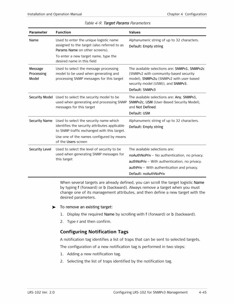
Installation and Operation Manual Chapter 4 Configuration
LRS-102 Ver. 2.0 Configuring LRS-102 for SNMPv3 Management 4-45
Table 4-9. Target Params Parameters
Parameter Function Values
Name Used to enter the unique logistic name
assigned to the target (also referred to as
Params Name on other screens).
To enter a new target name, type the
desired name in this field
Alphanumeric string of up to 32 characters.
Default: Empty string
Message
Processing
Model
Used to select the message processing
model to be used when generating and
processing SNMP messages for this target
The available selections are: SNMPv1, SNMPv2c
(SNMPv2 with community-based security
model), SNMPv2u (SNMPv2 with user-based
security model (USM)), and SNMPv3.
Default: SNMPv3
Security Model Used to select the security model to be
used when generating and processing SNMP
messages for this target
The available selections are: Any, SNMPv1,
SNMPv2c, USM (User-Based Security Model),
and Not Defined.
Default: USM
Security Name Used to select the security name which
identifies the security attributes applicable
to SNMP traffic exchanged with this target.
Use one of the names configured by means
of the Users screen
Alphanumeric string of up to 32 characters.
Default: Empty string
Security Level Used to select the level of security to be
used when generating SNMP messages for
this target
The available selections are:
noAuthNoPriv – No authentication, no privacy.
authNoPriv – With authentication, no privacy.
authPriv – With authentication and privacy.
Default: noAuthNoPriv
When several targets are already defined, you can scroll the target logistic Name by typing f (forward) or b (backward). Always remove a target when you must change one of its management attributes, and then define a new target with the desired parameters.
To remove an existing target:
1. Display the required Name by scrolling with f (forward) or b (backward).
2. Type r and then confirm.
Configuring Notification Tags
A notification tag identifies a list of traps that can be sent to selected targets.
The configuration of a new notification tag is performed in two steps:
1. Adding a new notification tag.
2. Selecting the list of traps identified by the notification tag.
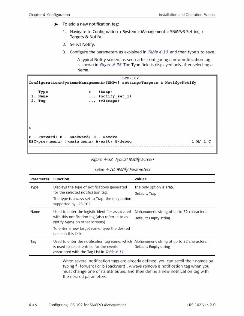
Chapter 4 Configuration Installation and Operation Manual
4-46 Configuring LRS-102 for SNMPv3 Management LRS-102 Ver. 2.0
To add a new notification tag:
1. Navigate to Configuration > System > Management > SNMPv3 Setting > Targets & Notify.
2. Select Notify.
3. Configure the parameters as explained in Table 4-10, and then type s to save.
A typical Notify screen, as seen after configuring a new notification tag, is shown in Figure 4-38. The Type field is displayed only after selecting a Name.
LRS-102 Configuration>System>Management>SNMPv3 setting>Targets & Notify>Notify Type > (trap) 1. Name ... (notify_set_1) 2. Tag ... (v3traps) > F - Forward; B - Backward; R - Remove ESC-prev.menu; !-main menu; &-exit; @-debug 1 M/ 1 C -----------------------------------------------------------------------------
Figure 4-38. Typical Notify Screen
Table 4-10. Notify Parameters
Parameter Function Values
Type Displays the type of notifications generated
for the selected notification tag.
The type is always set to Trap, the only option
supported by LRS-102
The only option is Trap.
Default: Trap
Name Used to enter the logistic identifier associated
with this notification tag (also referred to as
Notify Name on other screens).
To enter a new target name, type the desired
name in this field
Alphanumeric string of up to 32 characters.
Default: Empty string
Tag Used to enter the notification tag name, which
is used to select entries for the events
associated with the Tag List in Table 4-11
Alphanumeric string of up to 32 characters.
Default: Empty string
When several notification tags are already defined, you can scroll their names by typing f (forward) or b (backward). Always remove a notification tag when you must change one of its attributes, and then define a new notification tag with the desired parameters.
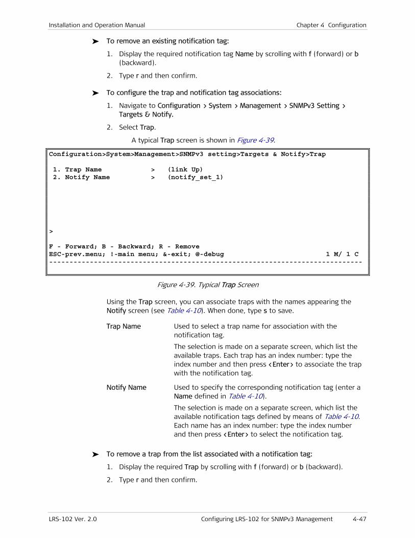
Installation and Operation Manual Chapter 4 Configuration
LRS-102 Ver. 2.0 Configuring LRS-102 for SNMPv3 Management 4-47
To remove an existing notification tag:
1. Display the required notification tag Name by scrolling with f (forward) or b (backward).
2. Type r and then confirm.
To configure the trap and notification tag associations:
1. Navigate to Configuration > System > Management > SNMPv3 Setting > Targets & Notify.
2. Select Trap.
A typical Trap screen is shown in Figure 4-39.
Configuration>System>Management>SNMPv3 setting>Targets & Notify>Trap 1. Trap Name > (link Up) 2. Notify Name > (notify_set_1) > F - Forward; B - Backward; R - Remove ESC-prev.menu; !-main menu; &-exit; @-debug 1 M/ 1 C -----------------------------------------------------------------------------
Figure 4-39. Typical Trap Screen
Using the Trap screen, you can associate traps with the names appearing the Notify screen (see Table 4-10). When done, type s to save.
Trap Name Used to select a trap name for association with the notification tag.
The selection is made on a separate screen, which list the available traps. Each trap has an index number: type the index number and then press <Enter> to associate the trap with the notification tag.
Notify Name Used to specify the corresponding notification tag (enter a Name defined in Table 4-10).
The selection is made on a separate screen, which list the available notification tags defined by means of Table 4-10. Each name has an index number: type the index number and then press <Enter> to select the notification tag.
To remove a trap from the list associated with a notification tag:
1. Display the required Trap by scrolling with f (forward) or b (backward).
2. Type r and then confirm.
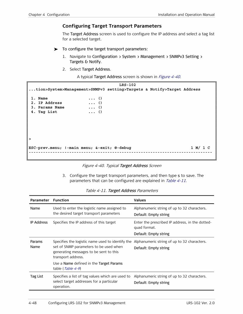
Chapter 4 Configuration Installation and Operation Manual
4-48 Configuring LRS-102 for SNMPv3 Management LRS-102 Ver. 2.0
Configuring Target Transport Parameters
The Target Address screen is used to configure the IP address and select a tag list for a selected target.
To configure the target transport parameters:
1. Navigate to Configuration > System > Management > SNMPv3 Setting > Targets & Notify.
2. Select Target Address.
A typical Target Address screen is shown in Figure 4-40.
LRS-102 ...tion>System>Management>SNMPv3 setting>Targets & Notify>Target Address 1. Name ... () 2. IP Address ... () 3. Params Name ... () 4. Tag List ... () > ESC-prev.menu; !-main menu; &-exit; @-debug 1 M/ 1 C -----------------------------------------------------------------------------
Figure 4-40. Typical Target Address Screen
3. Configure the target transport parameters, and then type s to save. The parameters that can be configured are explained in Table 4-11.
Table 4-11. Target Address Parameters
Parameter Function Values
Name Used to enter the logistic name assigned to
the desired target transport parameters
Alphanumeric string of up to 32 characters.
Default: Empty string
IP Address Specifies the IP address of this target Enter the prescribed IP address, in the dotted-
quad format.
Default: Empty string
Params
Name
Specifies the logistic name used to identify the
set of SNMP parameters to be used when
generating messages to be sent to this
transport address.
Use a Name defined in the Target Params
table (Table 4-9)
Alphanumeric string of up to 32 characters.
Default: Empty string
Tag List Specifies a list of tag values which are used to
select target addresses for a particular
operation.
Alphanumeric string of up to 32 characters.
Default: Empty string
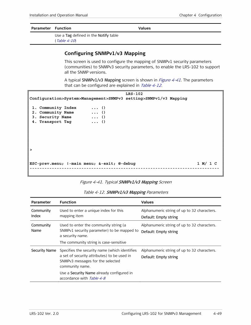
Installation and Operation Manual Chapter 4 Configuration
LRS-102 Ver. 2.0 Configuring LRS-102 for SNMPv3 Management 4-49
Parameter Function Values
Use a Tag defined in the Notify table
(Table 4-10)
Configuring SNMPv1/v3 Mapping
This screen is used to configure the mapping of SNMPv1 security parameters (communities) to SNMPv3 security parameters, to enable the LRS-102 to support all the SNMP versions.
A typical SNMPv1/v3 Mapping screen is shown in Figure 4-41. The parameters that can be configured are explained in Table 4-12.
LRS-102 Configuration>System>Management>SNMPv3 setting>SNMPv1/v3 Mapping 1. Community Index ... () 2. Community Name ... () 3. Security Name ... () 4. Transport Tag ... () > ESC-prev.menu; !-main menu; &-exit; @-debug 1 M/ 1 C -----------------------------------------------------------------------------
Figure 4-41. Typical SNMPv1/v3 Mapping Screen
Table 4-12. SNMPv1/v3 Mapping Parameters
Parameter Function Values
Community
Index
Used to enter a unique index for this
mapping item
Alphanumeric string of up to 32 characters.
Default: Empty string
Community
Name
Used to enter the community string (a
SNMPv1 security parameter) to be mapped to
a security name.
The community string is case-sensitive
Alphanumeric string of up to 32 characters.
Default: Empty string
Security Name Specifies the security name (which identifies
a set of security attributes) to be used in
SNMPv3 messages for the selected
community name.
Use a Security Name already configured in
accordance with Table 4-8
Alphanumeric string of up to 32 characters.
Default: Empty string
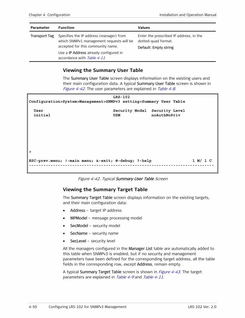
Chapter 4 Configuration Installation and Operation Manual
4-50 Configuring LRS-102 for SNMPv3 Management LRS-102 Ver. 2.0
Parameter Function Values
Transport Tag Specifies the IP address (manager) from
which SNMPv1 management requests will be
accepted for this community name.
Use a IP Address already configured in
accordance with Table 4-11
Enter the prescribed IP address, in the
dotted-quad format.
Default: Empty string
Viewing the Summary User Table
The Summary User Table screen displays information on the existing users and their main configuration data. A typical Summary User Table screen is shown in Figure 4-42. The user parameters are explained in Table 4-8.
LRS-102 Configuration>System>Management>SNMPv3 setting>Summary User Table User Security Model Security Level initial USM noAuthNoPriv > ESC-prev.menu; !-main menu; &-exit; @-debug; ?-help 1 M/ 1 C -----------------------------------------------------------------------------
Figure 4-42. Typical Summary User Table Screen
Viewing the Summary Target Table
The Summary Target Table screen displays information on the existing targets, and their main configuration data:
• Address – target IP address
• MPModel – message processing model
• SecModel – security model
• SecName – security name
• SecLevel – security level
All the managers configured in the Manager List table are automatically added to this table when SNMPv3 is enabled, but if no security and management parameters have been defined for the corresponding target address, all the table fields in the corresponding row, except Address, remain empty.
A typical Summary Target Table screen is shown in Figure 4-43. The target parameters are explained in Table 4-9 and Table 4-11.
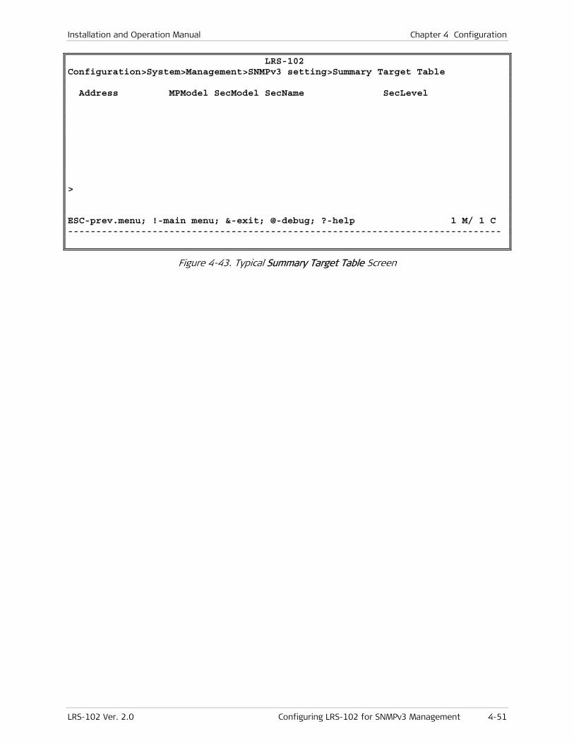
Installation and Operation Manual Chapter 4 Configuration
LRS-102 Ver. 2.0 Configuring LRS-102 for SNMPv3 Management 4-51
LRS-102 Configuration>System>Management>SNMPv3 setting>Summary Target Table Address MPModel SecModel SecName SecLevel > ESC-prev.menu; !-main menu; &-exit; @-debug; ?-help 1 M/ 1 C -----------------------------------------------------------------------------
Figure 4-43. Typical Summary Target Table Screen
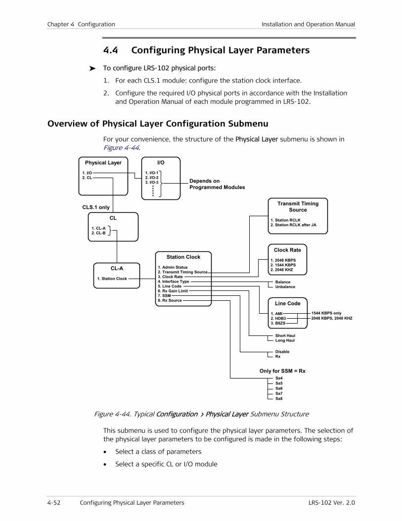
Chapter 4 Configuration Installation and Operation Manual
4-52 Configuring Physical Layer Parameters LRS-102 Ver. 2.0
4.4 Configuring Physical Layer Parameters
To configure LRS-102 physical ports:
1. For each CLS.1 module: configure the station clock interface.
2. Configure the required I/O physical ports in accordance with the Installation and Operation Manual of each module programmed in LRS-102.
Overview of Physical Layer Configuration Submenu
For your convenience, the structure of the Physical Layer submenu is shown in Figure 4-44.
Station Clock
1. Admin Status 2. Transmit Timing Source 3. Clock Rate 4. Interface Type 5. Line Code 6. Rx Gain Limit 7. SSM 8. Rx Source
Physical Layer
1. I/O 2. CL
I/O
1. I/O-1 2. I/O-2 3. I/O-3 . . . . .
Depends onProgrammed Modules
CL
1. CL-A 2. CL-B
CL-A
1. Station Clock
Transmit TimingSource
1. Station RCLK 2. Station RCLK after JA
Clock Rate
1. 2048 KBPS 2. 1544 KBPS 2. 2048 KHZ
Short HaulLong Haul
BalanceUnbalance
Line Code
1. AMI 2. HDB3 3. B8ZS
1544 KBPS only2048 KBPS, 2048 KHZ
CLS.1 only
Only for SSM = Rx
DisableRx
Sa4Sa5Sa6Sa7Sa8
Figure 4-44. Typical Configuration > Physical Layer Submenu Structure
This submenu is used to configure the physical layer parameters. The selection of the physical layer parameters to be configured is made in the following steps:
• Select a class of parameters
• Select a specific CL or I/O module
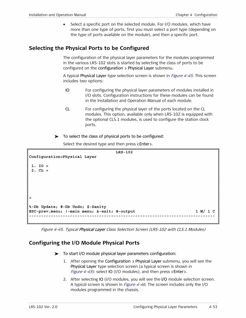
Installation and Operation Manual Chapter 4 Configuration
LRS-102 Ver. 2.0 Configuring Physical Layer Parameters 4-53
• Select a specific port on the selected module. For I/O modules, which have more than one type of ports, first you must select a port type (depending on the type of ports available on the module), and then a specific port.
Selecting the Physical Ports to be Configured
The configuration of the physical layer parameters for the modules programmed in the various LRS-102 slots is started by selecting the class of ports to be configured on the configuration > Physical Layer submenu.
A typical Physical Layer type selection screen is shown in Figure 4-45. This screen includes two options:
IO For configuring the physical layer parameters of modules installed in I/O slots. Configuration instructions for these modules can be found in the Installation and Operation Manual of each module.
CL For configuring the physical layer of the ports located on the CL modules. This option, available only when LRS-102 is equipped with the optional CLS.1 modules, is used to configure the station clock ports.
To select the class of physical ports to be configured:
Select the desired type and then press <Enter>.
LRS-102 Configuration>Physical Layer 1. IO > 2. CL > > %-Db Update; #-Db Undo; $-Sanity ESC-prev.menu; !-main menu; &-exit; @-output 1 M/ 1 C -----------------------------------------------------------------------------
Figure 4-45. Typical Physical Layer Class Selection Screen (LRS-102 with CLS.1 Modules)
Configuring the I/O Module Physical Ports
To start I/O module physical layer parameters configuration:
1. After opening the Configuration > Physical Layer submenu, you will see the Physical Layer type selection screen (a typical screen is shown in Figure 4-45): select IO (I/O modules), and then press <Enter>.
2. After selecting IO (I/O modules, you will see the I/O module selection screen. A typical screen is shown in Figure 4-46. The screen includes only the I/O modules programmed in the chassis.

Chapter 4 Configuration Installation and Operation Manual
4-54 Configuring Physical Layer Parameters LRS-102 Ver. 2.0
LRS-102 Configuration>Physical Layer>I/O 1. I/O 1 (OP108C/B)> 2. I/O 2 (OP106C/B)> 3. I/O 3 (ASMi54C)> > %-Db Update; #-Db Undo; $-Sanity ESC-prev.menu; !-main menu; &-exit; @-output 1 M/ 1 C -----------------------------------------------------------------------------
Figure 4-46. Typical I/O Module Selection Screen
3. Select a module from the list by typing the number corresponding to its slot, and then press <Enter>.
4. For I/O modules that have more than one type of physical ports, you will see the port type selection screen.
Refer to the module Installation and Operation Manual for detailed configuration instructions.
Configuring the CLS.1 Station Clock Port
To configure the physical layer parameters of the station clock port located on a selected CLS.1 module, use the Configuration > Physical Layer > CL screen. For LRS-102 equipped with two CLS.1 modules, each station clock port can be separately configured.
To select the CLS.1 configuration task:
1. Select CL on the Physical Layer submenu. A typical CLS.1 module selection screen is shown in Figure 4-47. This screen is used to select between the two CLS.1 modules that can be installed in the LRS-102.
LRS-102 Configuration>Physical Layer>CL 1. CL-A> 2. CL-B> > %-Db Update; #-Db Undo; $-Sanity ESC-prev.menu; !-main menu; &-exit; @-output 1 M/ 1 C -----------------------------------------------------------------------------
Figure 4-47. Configuration > Physical Layer > CL Selection Screen
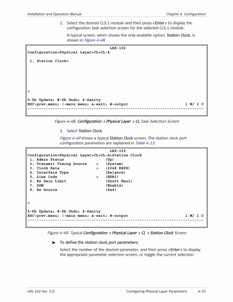
Installation and Operation Manual Chapter 4 Configuration
LRS-102 Ver. 2.0 Configuring Physical Layer Parameters 4-55
2. Select the desired CLS.1 module and then press <Enter> to display the configuration task selection screen for the selected CLS.1 module.
A typical screen, which shows the only available option, Station Clock, is shown in Figure 4-48.
LRS-102 Configuration>Physical Layer>CL>CL-A 1. Station Clock> > %-Db Update; #-Db Undo; $-Sanity ESC-prev.menu; !-main menu; &-exit; @-output 1 M/ 1 C -----------------------------------------------------------------------------
Figure 4-48. Configuration > Physical Layer > CL Task Selection Screen
3. Select Station Clock.
Figure 4-49 shows a typical Station Clock screen. The station clock port configuration parameters are explained in Table 4-13.
LRS-102 Configuration>Physical Layer>CL>CL-A>Station Clock 1. Admin Status (Up) 2. Transmit Timing Source > (System) 3. Clock Rate > (2048 KBPS) 4. Interface Type (Balance) 5. Line Code > (HDB3) 6. Rx Gain Limit (Short Haul) 7. SSM (Enable) 8. Rx Source (Sa4) > %-Db Update; #-Db Undo; $-Sanity ESC-prev.menu; !-main menu; &-exit; @-output 1 M/ 1 C -----------------------------------------------------------------------------
Figure 4-49. Typical Configuration > Physical Layer > CL > Station Clock Screen
To define the station clock port parameters:
Select the number of the desired parameter, and then press <Enter> to display the appropriate parameter selection screen, or toggle the current selection.

Chapter 4 Configuration Installation and Operation Manual
4-56 Configuring Physical Layer Parameters LRS-102 Ver. 2.0
Table 4-13. Station Clock Parameters
Parameter Function Values
Admin Status Used to enable/disable the station
clock interface
DOWN – The station clock interface on the
corresponding CLS.1 module is disabled. This state
should be selected as long as the port configuration
has not yet been completed, or to stop using this port.
UP – The station clock interface on the corresponding
CLS.1 module is enabled.
Default: DOWN
Transmit Timing
Source
Selects the source of the clock
output signal provided in the
station clock connector, for
connection to other equipment
SYSTEM – the output (transmit) clock is derived from
the LRS-102 internal oscillator timing, operating in the
free-running mode. In this case, the nominal frequency
of the output clock is always 2048 kbps, irrespective of
the Clock Rate selection. This option is not available
when Clock Rate is 1544 KBPS.
STATION RCLK – the external clock signal applied to the
station clock receive input is returned through the
transmit output.
STATION RCLK AFTER JA – the external clock signal
applied to the station clock receive input is regenerated
and filtered by a jitter attenuator, before being
returned through the transmit output. This is the
recommended selection.
Default: SYSTEM
Clock Rate Selects the rate and type of signal
accepted and transmitted via the
station clock port
2048 KBPS – 2.048 Mbps signal per ITU-T Rec. G.703
Para. 6.
2048 KHZ – 2.048 MHz signal per ITU-T Rec. G.703
Para. 10.
1544 KBPS – 1.544 Mbps signal per ITU-T Rec. G.703
Para. 2. This option is not available when Transmit
Timing Source is SYSTEM.
Default: 2048 KBPS
Interface Type Selects the clock signal interface
type.
This parameter is displayed only
when Clock Rate is 2048 KBPS
BALANCE – balanced interface (nominal impedance of
100 Ω for 1544 KBPS, and 120 Ω for 2048 KBPS and
2048 kHz).
UNBALANCE – 75 Ω unbalanced (coaxial) interface. This
selection is available only for 2048 KBPS.
Default: BALANCE
Line Code Selects the line code.
This parameter is displayed only
when Clock Rate is 2048 KBPS or
1544 KBPS
The available selections depend on Clock Rate:
• When Clock Rate is 2048 KBPS or 2048 kHz, the
only selection is HDB3.
• When Clock Rate is 1544 KBPS:
AMI – alternate mark inversion coding
B8ZS – Binary-8 zero suppression coding
Default: HDB3

Installation and Operation Manual Chapter 4 Configuration
LRS-102 Ver. 2.0 Configuring Physical Layer Parameters 4-57
Parameter Function Values
Rx Gain Limit Determines the maximum
attenuation of the receive signal
that can be compensated for by
the station port receive path.
This parameter is displayed only
when Clock Rate is 2048 KBPS or
1544 KBPS, and Interface Type is
BALANCE
SHORT HAUL – Maximum allowable attenuation of
10 dB, relative to the nominal transmit level (similar to
DSU capabilities).
LONG HAUL – Maximum allowable attenuation of 34 dB,
relative to the nominal transmit level (similar to DSU
capabilities).
Default: SHORT HAUL
SSM Enables/disables the use of SSM
messages received through this
station clock interface
DISABLE – SSM messages received through this station
clock interface are ignored.
RX – SSM messages received through the station clock
interface can be displayed, to read station clock quality.
Default: DISABLE
Rx Source Specifies the national bit (located
in timeslot 0 of E1 streams) from
which the SSM message is read.
This parameter is displayed only
when Clock Rate is 2048 KBPS and
SSM is Rx Source
Sa4, Sa5, Sa6, Sa7, Sa8 – the national bit carrying the
SSM.
Default: Sa4

Chapter 4 Configuration Installation and Operation Manual
4-58 Configuring Ethernet Applications LRS-102 Ver. 2.0
4.5 Configuring Ethernet Applications
Ethernet traffic is forwarded within LRS-102 (or flows) among specified end points (referred to as bridge ports) in accordance with user-configured rules that define Ethernet Virtual Connections (flows). Therefore, Ethernet applications are configured by defining flows within the LRS-102. A flow interconnects at least two bridge ports, however a given bridge port can serve as the termination point of several flows. The maximum number of flows that can be defined on an LRS-102 is 250.
The current LRS-102 version supports E-line flows (an E-line is a type of Ethernet virtual connection that interconnects exactly two bridge ports).
The bridge ports that can be defined depend on the installed module types:
• For OP-108C and OP-106C modules, the following types of bridge ports can be defined:
One bridge port can be defined on each Ethernet physical interface.
One bridge port can be defined on each external link (actually, this bridge port is configured on an internal logical Ethernet port, which supports the Ethernet traffic to the OP-108C or OP-106C external link). Note that external link A is served by the LINK 1 and LINK 2 ports, and external link B is served by the LINK 3 and LINK 4 ports.
Thus, each OP-108C and OP-106C has two bridge ports defined on Ethernet ports, and two bridge ports defined on the external links.
• For ASMi-54C modules, two types of bridge ports can be defined:
Each PCS configured on the module SHDSL ports.
Each Ethernet physical port can also serve as a bridge port.
The maximum number of bridge ports that can be defined on an ASMi-54C module, together with the two Ethernet ports, is up to 10.
The total number of bridge ports supported by a LRS-102 is 370.
Use the Configuration > Applications submenu to configure Ethernet traffic flows.

Installation and Operation Manual Chapter 4 Configuration
LRS-102 Ver. 2.0 Configuring Ethernet Applications 4-59
Overview of Applications Submenu
Figure 4-50 shows the detailed structure of the Applications submenu.
Applications 1. Ethernet Services
Ethernet Services 1. Flows
Flows 1. Flow 2. Name 3. Flow Type 4. Bridge Port Mapping
Flow Type 1. E-LINE 2. E-LAN
Add (A)
Bridge Port Mapping
BP C-VLAN Type C-VLAN ID SP-VLAN Slot Port Rate BP Name
C-VLAN Type 1. Unaware 2. Aware
Reserved
Bridge Port Mapping
Flow Flow Name C-VLAN ID SP-VLAN
Display List (U)
Bridge Port Mapping BP 1. C-VLAN Type C-VLAN ID 2. SP-VLAN 3. Slot Port Rate BP Name
Figure 4-50. Configuration > Applications Submenu Structure
Configuring Ethernet Flows
Two types of flows can be configured:
• Traffic flows
• Management flows.
Traffic Flow Configuration Guidelines
The maximum number of traffic flows that can be defined on an LRS-102 is 250 (an additional flow, assigned the identifier 251, can be configured for management only). The following configuration rules apply to flows and bridge ports:
1. A bridge port can terminate either only traffic flows from local ports (ports on the same module).
2. It is not possible to configure flows between Ethernet ports on the same I/O module, but only flows between different type of bridge ports on the same I/O module, in accordance with the following rules:

Chapter 4 Configuration Installation and Operation Manual
4-60 Configuring Ethernet Applications LRS-102 Ver. 2.0
For OP-108C and OP-106C, you can configure only flows between an Ethernet port and the internal (virtual) Ethernet port associated with the corresponding external link, Int_Eth1 or Int_Eth2.
For ASMi-54C modules, you can configure only flows between an Ethernet port and a PCS configured on a module SHDSL port, and flows between two different PCSs of the same module.
3. A bridge port can terminate only one traffic flow classified as unaware (i.e., which does not discriminate Ethernet traffic in accordance with customer’s and service provider’s VLANs).
4. When a bridge port is mapped to more than one traffic flow, the bridge port can terminate several traffic flows with specific VLAN IDs, but only one traffic flow classified as unaware.
5. A bridge port can terminate any number of traffic flows with specific VLAN IDs (aware mode), up to the maximum supported per system.
LRS-102 flow configuration menu allows selecting between E-line flows and E-LAN flows. The current LRS-102 version does not support E-LAN flows.
6. For E-line flows, the following VLAN assignment rules apply:
1. The bridge ports terminating a flow must use the same VLAN mode (either unaware or aware).
2. When using the aware mode:
The same VLAN ID must be configured at both bridge ports.
A given VLAN ID can be configured on only one Ethernet flow per module.
Traffic Flow Configuration Procedure
To add a new traffic flow:
1. On the Configuration > Applications menu, select Ethernet Services.
2. On the Ethernet Services screen, select Flows.
You will see the traffic flow configuration screen. A typical screen is shown in Figure 4-51. If no flow is yet defined, it is always necessary to add a new flow.
Note
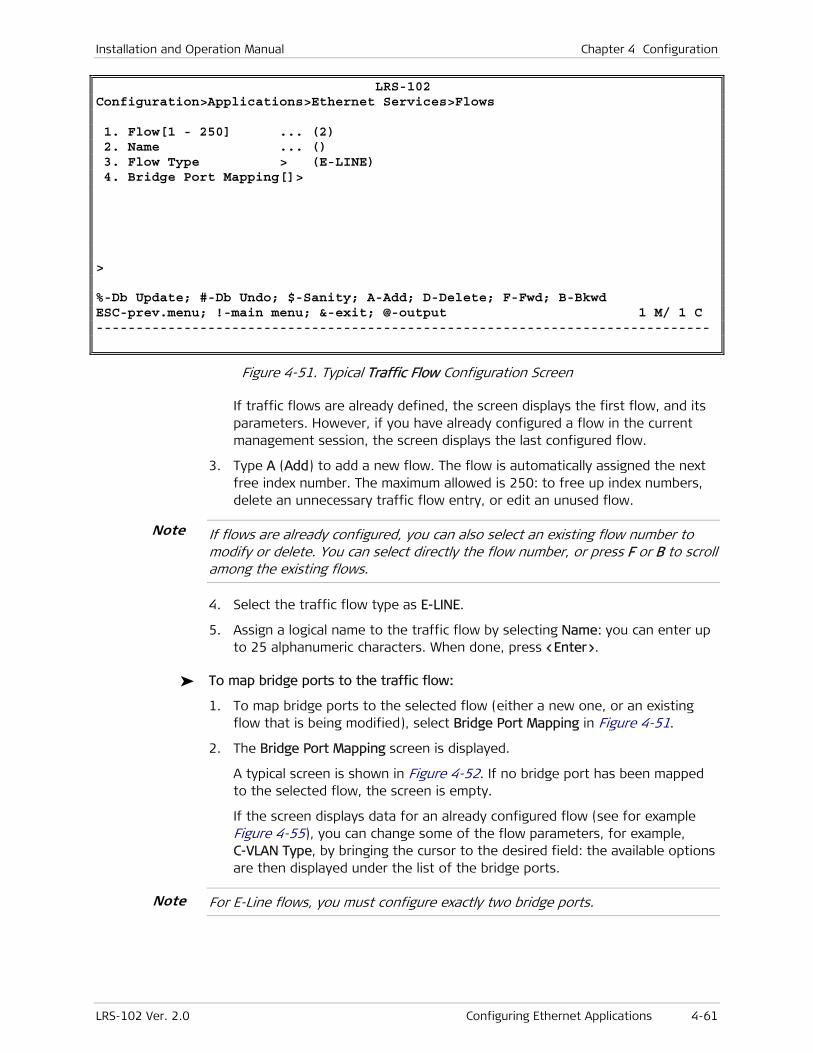
Installation and Operation Manual Chapter 4 Configuration
LRS-102 Ver. 2.0 Configuring Ethernet Applications 4-61
LRS-102 Configuration>Applications>Ethernet Services>Flows 1. Flow[1 - 250] ... (2) 2. Name ... () 3. Flow Type > (E-LINE) 4. Bridge Port Mapping[]> > %-Db Update; #-Db Undo; $-Sanity; A-Add; D-Delete; F-Fwd; B-Bkwd ESC-prev.menu; !-main menu; &-exit; @-output 1 M/ 1 C -----------------------------------------------------------------------------
Figure 4-51. Typical Traffic Flow Configuration Screen
If traffic flows are already defined, the screen displays the first flow, and its parameters. However, if you have already configured a flow in the current management session, the screen displays the last configured flow.
3. Type A (Add) to add a new flow. The flow is automatically assigned the next free index number. The maximum allowed is 250: to free up index numbers, delete an unnecessary traffic flow entry, or edit an unused flow.
If flows are already configured, you can also select an existing flow number to modify or delete. You can select directly the flow number, or press F or B to scroll among the existing flows.
4. Select the traffic flow type as E-LINE.
5. Assign a logical name to the traffic flow by selecting Name: you can enter up to 25 alphanumeric characters. When done, press <Enter>.
To map bridge ports to the traffic flow:
1. To map bridge ports to the selected flow (either a new one, or an existing flow that is being modified), select Bridge Port Mapping in Figure 4-51.
2. The Bridge Port Mapping screen is displayed.
A typical screen is shown in Figure 4-52. If no bridge port has been mapped to the selected flow, the screen is empty.
If the screen displays data for an already configured flow (see for example Figure 4-55), you can change some of the flow parameters, for example, C-VLAN Type, by bringing the cursor to the desired field: the available options are then displayed under the list of the bridge ports.
For E-Line flows, you must configure exactly two bridge ports.
Note
Note

Chapter 4 Configuration Installation and Operation Manual
4-62 Configuring Ethernet Applications LRS-102 Ver. 2.0
LRS-102 ...ration>Applications>Ethernet Services>Flows>Bridge Port Mapping-Flow3 BP C-VLAN Type C-VLAN ID SP-VLAN Slot Port Rate BP Name > A-Add;%-Db Update; #-Db Undo; $-Sanity; F-Fwd; B-Bkwd; U-BP-Flow ESC-prev.menu; !-main menu; &-exit; @-output; ?-help 1 M/ 1 C -----------------------------------------------------------------------------
Figure 4-52. Typical Bridge Port Mapping Screen for Traffic Flow (Before Configuration)
3. On the Bridge Port Mapping screen, type A (Add) to add a new bridge port.
4. You will see the bridge port mapping data form. A typical screen with the default values is shown in Figure 4-53.
LRS-102 ...ration>Applications>Ethernet Services>Flows>Bridge Port Mapping-Flow1 BP[1 - 512] ... (68) 1. C-VLAN Type > (Aware) 2. C-VLAN ID[1 - 4094] ... (3) SP-VLAN[0 - 4094] ... (0) Slot > (IO-2) Port > (ETH 1) Rate > (100Mbps) BP Name ... () > #-Db Undo; F-Fwd; B-Bkwd ESC-prev.menu; !-main menu; &-exit; @-output 1 M/ 1 C -----------------------------------------------------------------------------
Figure 4-53. Typical Bridge Port Mapping Data Form for Traffic Flow
5. Start by selecting an available bridge port, by pressing F or B: the Slot and Port fields are automatically scrolled to display the available bridge ports.
The Slot field displays only slots of modules on which bridge ports are still available.

Installation and Operation Manual Chapter 4 Configuration
LRS-102 Ver. 2.0 Configuring Ethernet Applications 4-63
The Port field displays the port type, followed by its index number on the selected slot. Bridge ports that are already not available are automatically skipped as you configure flows, for example:
1. Any bridge port configured as VLAN-unaware in one flow cannot be reused in another flow. A sanity error message will be generated if you try including the same bridge port in another flow.
2. The maximum allowed number of traffic flows is 250, and therefore after reaching this number, no more flows can be added.
Alternatively, select manually the desired Slot number, and scroll the bridge ports available on the selected module.
6. Select the prescribed flow parameters, taking into consideration the configuration guidelines presented on page 4-59. Table 4-14 lists the available parameters. The fields displayed on the screen automatically adjust to the selected values.
Table 4-14. Traffic Flow Bridge Port Mapping Parameters
Parameter Function Values
BP Displays the internal index number of
the bridge port being defined. The
port number is automatically assigned
by the LRS-102 management
subsystem.
The index number indicates the
location and type of the bridge port
for the internal processor, and
therefore it changes when you make
changes to the Slot field
The available range is 1 to 512.
Default: 1
C-VLAN Type Specifies the classification method for
customer’s edge traffic arriving at the
selected bridge port
The selection is made on a submenu with the
following options:
AWARE – Only frames with the VLAN ID selected
in the C-VLAN ID field are accepted by this
bridge port.
UNAWARE – All frames are accepted.
Default: UNAWARE
C-VLAN ID Specifies the VLAN ID accepted when
the C-VLAN Type is AWARE.
This field can be modified only when
C-VLAN Type is AWARE
The allowed range is 1 to 4094. The selected
VLAN ID must be unique per bridge port, but can
be reused on different bridge ports.
0 means that no VLAN ID has been selected (this
is also the only value displayed when C-VLAN
Type is UNAWARE).
Default: 1
SP-VLAN Specifies the service provider’s edge
VLAN ID for the traffic at the selected
bridge port
The only allowed value is 0.
Default: 0
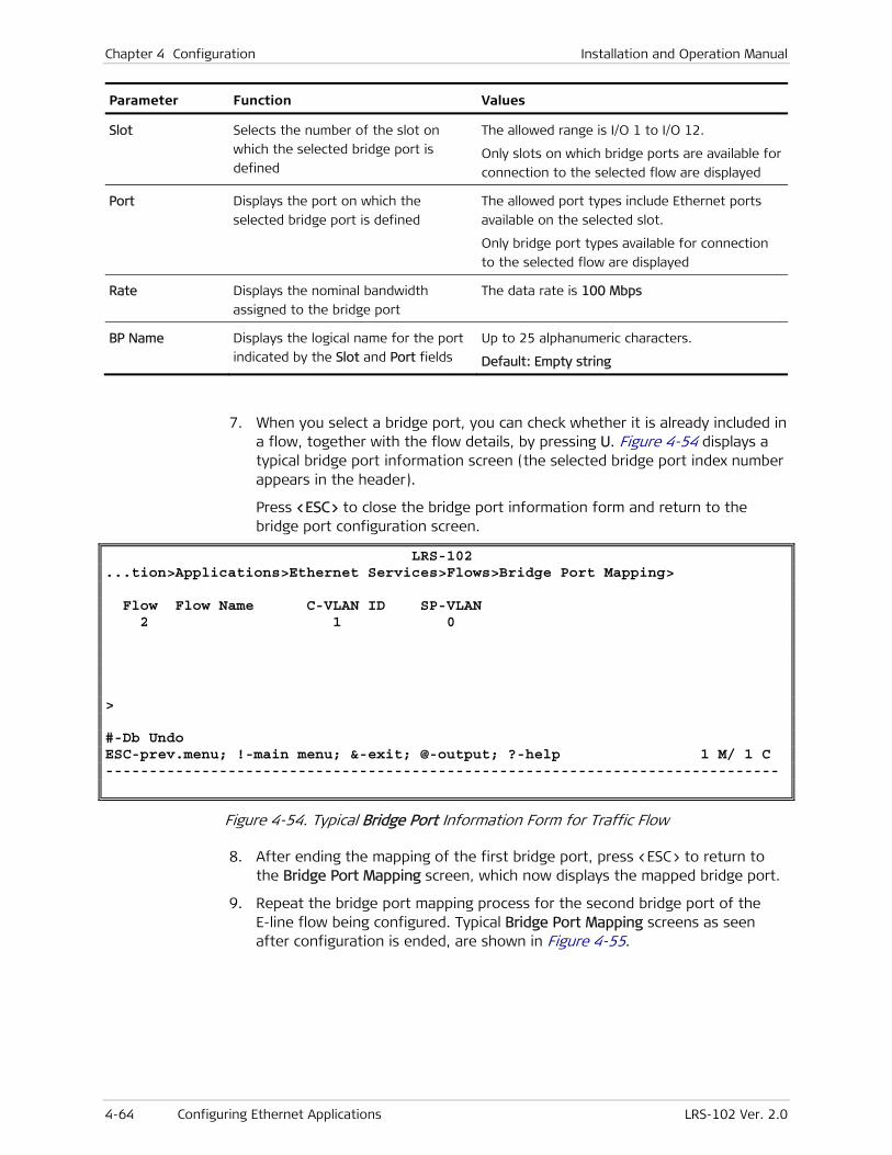
Chapter 4 Configuration Installation and Operation Manual
4-64 Configuring Ethernet Applications LRS-102 Ver. 2.0
Parameter Function Values
Slot Selects the number of the slot on
which the selected bridge port is
defined
The allowed range is I/O 1 to I/O 12.
Only slots on which bridge ports are available for
connection to the selected flow are displayed
Port Displays the port on which the
selected bridge port is defined
The allowed port types include Ethernet ports
available on the selected slot.
Only bridge port types available for connection
to the selected flow are displayed
Rate Displays the nominal bandwidth
assigned to the bridge port
The data rate is 100 Mbps
BP Name Displays the logical name for the port
indicated by the Slot and Port fields
Up to 25 alphanumeric characters.
Default: Empty string
7. When you select a bridge port, you can check whether it is already included in a flow, together with the flow details, by pressing U. Figure 4-54 displays a typical bridge port information screen (the selected bridge port index number appears in the header).
Press <ESC> to close the bridge port information form and return to the bridge port configuration screen.
LRS-102 ...tion>Applications>Ethernet Services>Flows>Bridge Port Mapping> Flow Flow Name C-VLAN ID SP-VLAN 2 1 0 > #-Db Undo ESC-prev.menu; !-main menu; &-exit; @-output; ?-help 1 M/ 1 C -----------------------------------------------------------------------------
Figure 4-54. Typical Bridge Port Information Form for Traffic Flow
8. After ending the mapping of the first bridge port, press <ESC> to return to the Bridge Port Mapping screen, which now displays the mapped bridge port.
9. Repeat the bridge port mapping process for the second bridge port of the E-line flow being configured. Typical Bridge Port Mapping screens as seen after configuration is ended, are shown in Figure 4-55.

Installation and Operation Manual Chapter 4 Configuration
LRS-102 Ver. 2.0 Configuring Ethernet Applications 4-65
LRS-102 ...ration>Applications>Ethernet Services>Flows>Bridge Port Mapping-Flow1 BP C-VLAN Type C-VLAN ID SP-VLAN Slot Port Rate BP Name 33 Aware 3 0 IO-1 ETH 1 100Mbps 34 Aware 3 0 IO-1 Int_Eth1 100Mbps 1. Unaware 2. Aware > A-Add;R-Remove;%-Db Update; #-Db Undo; $-Sanity; F-Fwd; B-Bkwd; U-BP-Flow ESC-prev.menu; !-main menu; &-exit; @-output; ?-help 1 M/ 1 C -----------------------------------------------------------------------------
Figure 4-55. Typical Bridge Port Mapping Screen (After Traffic Flow Configuration)
Management Flow Configuration Procedure
Management traffic flowing through Ethernet connections is normally assigned a dedicated VLAN. Within the LRS-102, inband management traffic can reach the management subsystem on the CL modules through Ethernet ports, or through the external links when carrying Ethernet traffic.
To control the flow of Ethernet inband management traffic within LRS-102 and enable its distribution, through the LRS-102 ports, to other equipment, it is necessary to configure a dedicated management flow, which is always assigned the flow identifier 251. The maximum number of bridge ports that can be added to a management flow is 96.
In addition to selecting the bridge ports connected to the management flow, when the same management traffic can be received through more than one bridge port, it is also necessary to specify which bridge ports may accept management traffic from managers (such ports are referred to as host NMS sources). If management communication through the currently selected port fails, another port is automatically selected.
When selecting host NMS source ports, make sure to plan ahead how to avoid forming loops in the Ethernet communication topology.
The traffic flow configuration rules listed in the Traffic Flow Configuration Guidelines section on page 4-59 also apply to the management flow.
To configure the management flow:
1. On the Configuration > System > Management menu, select Flow.
You will see the management flow configuration screen. A typical screen, as seen before a flow is configured, is shown in Figure 4-56. If no flow is yet defined, it is always necessary to add this flow.
Note
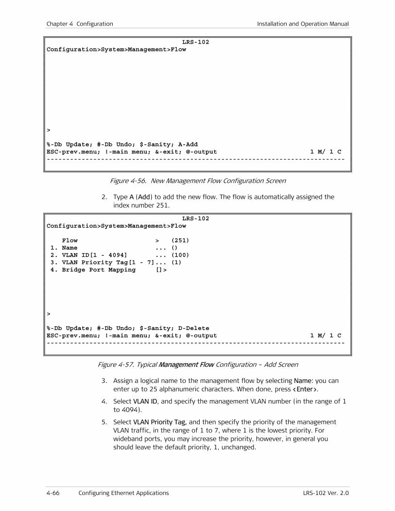
Chapter 4 Configuration Installation and Operation Manual
4-66 Configuring Ethernet Applications LRS-102 Ver. 2.0
LRS-102 Configuration>System>Management>Flow > %-Db Update; #-Db Undo; $-Sanity; A-Add ESC-prev.menu; !-main menu; &-exit; @-output 1 M/ 1 C -----------------------------------------------------------------------------
Figure 4-56. New Management Flow Configuration Screen
2. Type A (Add) to add the new flow. The flow is automatically assigned the index number 251.
LRS-102 Configuration>System>Management>Flow Flow > (251) 1. Name ... () 2. VLAN ID[1 - 4094] ... (100) 3. VLAN Priority Tag[1 - 7]... (1) 4. Bridge Port Mapping []> > %-Db Update; #-Db Undo; $-Sanity; D-Delete ESC-prev.menu; !-main menu; &-exit; @-output 1 M/ 1 C -----------------------------------------------------------------------------
Figure 4-57. Typical Management Flow Configuration – Add Screen
3. Assign a logical name to the management flow by selecting Name: you can enter up to 25 alphanumeric characters. When done, press <Enter>.
4. Select VLAN ID, and specify the management VLAN number (in the range of 1 to 4094).
5. Select VLAN Priority Tag, and then specify the priority of the management VLAN traffic, in the range of 1 to 7, where 1 is the lowest priority. For wideband ports, you may increase the priority, however, in general you should leave the default priority, 1, unchanged.
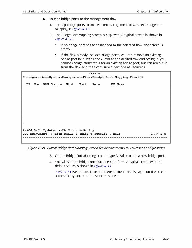
Installation and Operation Manual Chapter 4 Configuration
LRS-102 Ver. 2.0 Configuring Ethernet Applications 4-67
To map bridge ports to the management flow:
1. To map bridge ports to the selected management flow, select Bridge Port Mapping in Figure 4-57.
2. The Bridge Port Mapping screen is displayed. A typical screen is shown in Figure 4-58.
If no bridge port has been mapped to the selected flow, the screen is empty.
If the flow already includes bridge ports, you can remove an existing bridge port by bringing the cursor to the desired row and typing R (you cannot change parameters for an existing bridge port, but can remove it from the flow and then configure a new one as required).
LRS-102 Configuration>System>Management>Flow>Bridge Port Mapping-Flow251 BP Host NMS Source Slot Port Rate BP Name > A-Add;%-Db Update; #-Db Undo; $-Sanity ESC-prev.menu; !-main menu; &-exit; @-output; ?-help 1 M/ 1 C -----------------------------------------------------------------------------
Figure 4-58. Typical Bridge Port Mapping Screen for Management Flow (Before Configuration)
3. On the Bridge Port Mapping screen, type A (Add) to add a new bridge port.
4. You will see the bridge port mapping data form. A typical screen with the default values is shown in Figure 4-53.
Table 4-15 lists the available parameters. The fields displayed on the screen automatically adjust to the selected values.
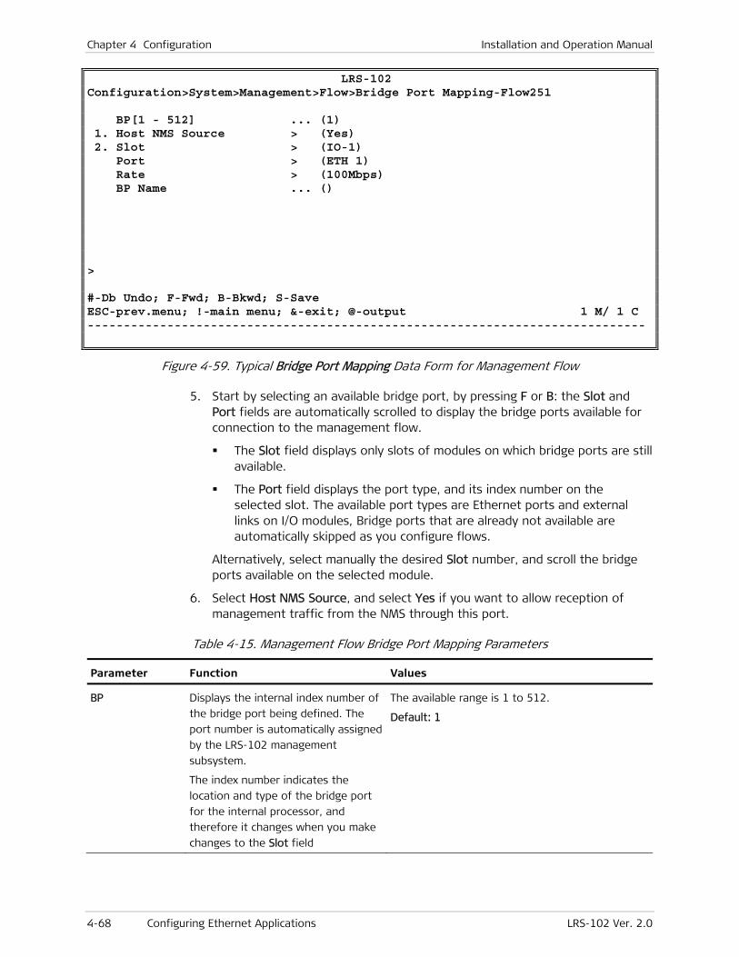
Chapter 4 Configuration Installation and Operation Manual
4-68 Configuring Ethernet Applications LRS-102 Ver. 2.0
LRS-102 Configuration>System>Management>Flow>Bridge Port Mapping-Flow251 BP[1 - 512] ... (1) 1. Host NMS Source > (Yes) 2. Slot > (IO-1) Port > (ETH 1) Rate > (100Mbps) BP Name ... () > #-Db Undo; F-Fwd; B-Bkwd; S-Save ESC-prev.menu; !-main menu; &-exit; @-output 1 M/ 1 C -----------------------------------------------------------------------------
Figure 4-59. Typical Bridge Port Mapping Data Form for Management Flow
5. Start by selecting an available bridge port, by pressing F or B: the Slot and Port fields are automatically scrolled to display the bridge ports available for connection to the management flow.
The Slot field displays only slots of modules on which bridge ports are still available.
The Port field displays the port type, and its index number on the selected slot. The available port types are Ethernet ports and external links on I/O modules, Bridge ports that are already not available are automatically skipped as you configure flows.
Alternatively, select manually the desired Slot number, and scroll the bridge ports available on the selected module.
6. Select Host NMS Source, and select Yes if you want to allow reception of management traffic from the NMS through this port.
Table 4-15. Management Flow Bridge Port Mapping Parameters
Parameter Function Values
BP Displays the internal index number of
the bridge port being defined. The
port number is automatically assigned
by the LRS-102 management
subsystem.
The index number indicates the
location and type of the bridge port
for the internal processor, and
therefore it changes when you make
changes to the Slot field
The available range is 1 to 512.
Default: 1
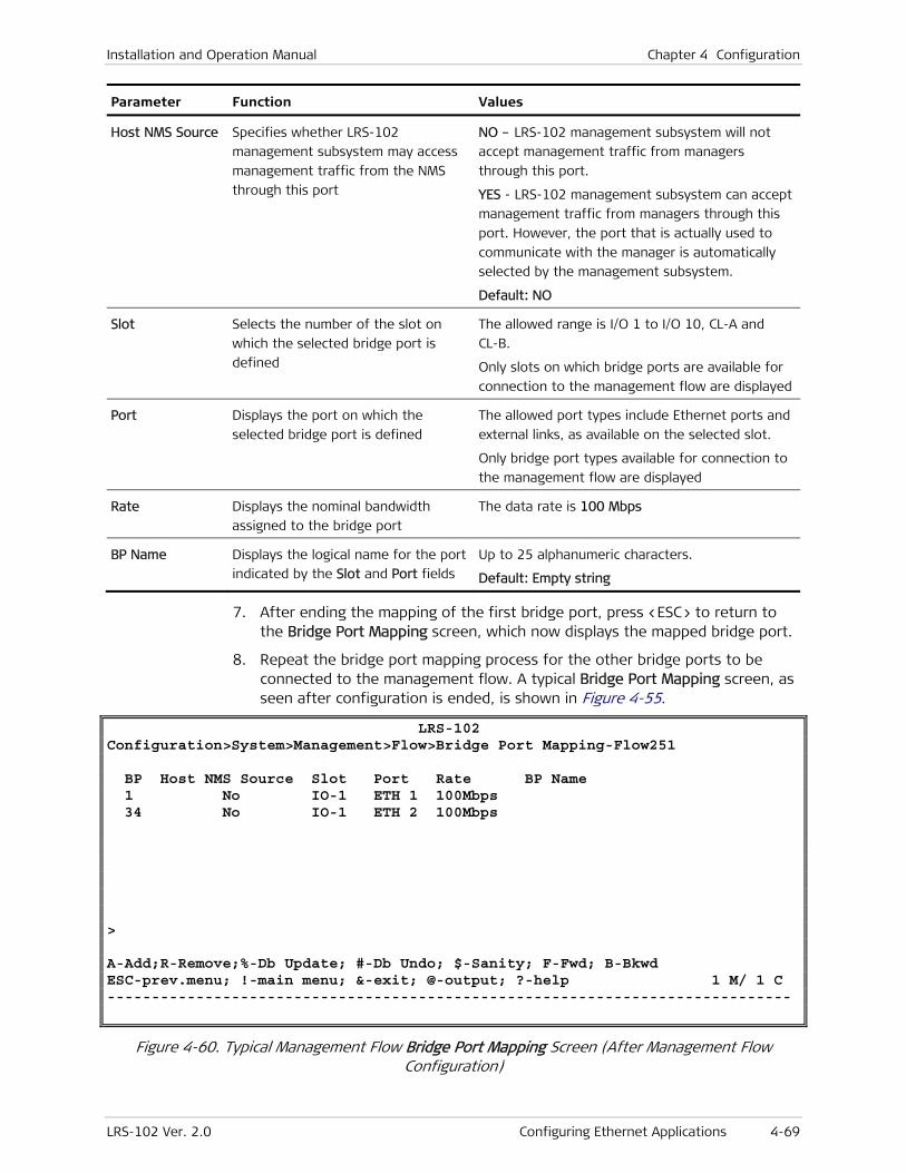
Installation and Operation Manual Chapter 4 Configuration
LRS-102 Ver. 2.0 Configuring Ethernet Applications 4-69
Parameter Function Values
Host NMS Source Specifies whether LRS-102
management subsystem may access
management traffic from the NMS
through this port
NO – LRS-102 management subsystem will not
accept management traffic from managers
through this port.
YES - LRS-102 management subsystem can accept
management traffic from managers through this
port. However, the port that is actually used to
communicate with the manager is automatically
selected by the management subsystem.
Default: NO
Slot Selects the number of the slot on
which the selected bridge port is
defined
The allowed range is I/O 1 to I/O 10, CL-A and
CL-B.
Only slots on which bridge ports are available for
connection to the management flow are displayed
Port Displays the port on which the
selected bridge port is defined
The allowed port types include Ethernet ports and
external links, as available on the selected slot.
Only bridge port types available for connection to
the management flow are displayed
Rate Displays the nominal bandwidth
assigned to the bridge port
The data rate is 100 Mbps
BP Name Displays the logical name for the port
indicated by the Slot and Port fields
Up to 25 alphanumeric characters.
Default: Empty string
7. After ending the mapping of the first bridge port, press <ESC> to return to the Bridge Port Mapping screen, which now displays the mapped bridge port.
8. Repeat the bridge port mapping process for the other bridge ports to be connected to the management flow. A typical Bridge Port Mapping screen, as seen after configuration is ended, is shown in Figure 4-55.
LRS-102 Configuration>System>Management>Flow>Bridge Port Mapping-Flow251 BP Host NMS Source Slot Port Rate BP Name 1 No IO-1 ETH 1 100Mbps 34 No IO-1 ETH 2 100Mbps > A-Add;R-Remove;%-Db Update; #-Db Undo; $-Sanity; F-Fwd; B-Bkwd ESC-prev.menu; !-main menu; &-exit; @-output; ?-help 1 M/ 1 C -----------------------------------------------------------------------------
Figure 4-60. Typical Management Flow Bridge Port Mapping Screen (After Management Flow Configuration)
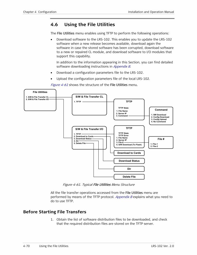
Chapter 4 Configuration Installation and Operation Manual
4-70 Using the File Utilities LRS-102 Ver. 2.0
4.6 Using the File Utilities
The File Utilities menu enables using TFTP to perform the following operations:
• Download software to the LRS-102. This enables you to update the LRS-102 software when a new release becomes available, download again the software in case the stored software has been corrupted, download software to a new or repaired CL module, and download software to I/O modules that support this capability.
In addition to the information appearing in this Section, you can find detailed software downloading instructions in Appendix B.
• Download a configuration parameters file to the LRS-102.
• Upload the configuration parameters file of the local LRS-102.
Figure 4-61 shows the structure of the File Utilities menu.
TFTP
TFTP State 1. File Name 2. Server IP 3. Command
File Utilities
1. S/W & File Transfer CL 2. S/W & File Transfer I/O
Command
1. SW Download 2. Config Download 3. Config Upload 4. No Command
S/W & File Transfer I/O
1. TFTP 2. Download to Cards 3. Download Status 4. Dir 5. Delete File
TFTP
TFTP State TFTP Error 1. File Name 2. Server IP 3. File # 4. S/W Download (To Flash)
Download to Cards
Dir
Delete File
Download Status
File #
1. File-1 2. File-2
S/W & File Transfer CL
1. TFTP
Figure 4-61. Typical File Utilities Menu Structure
All the file transfer operations accessed from the File Utilities menu are performed by means of the TFTP protocol. Appendix B explains what you need to do to use TFTP.
Before Starting File Transfers
1. Obtain the list of software distribution files to be downloaded, and check that the required distribution files are stored on the TFTP server.

Installation and Operation Manual Chapter 4 Configuration
LRS-102 Ver. 2.0 Using the File Utilities 4-71
2. Make sure that the TFTP server can communicate with the LRS-102, for example, by sending pings to the IP address assigned to the LRS-102 management entity (the host IP address).
File Transfers to CL Modules
File transfers to the CL modules are managed by means of the S/W & File Transfer CL submenu. Valid software image files have the extension .img, and configuration files have the extension .dat.
To select a file transfer task:
1. Open the File Utilities menu. A typical screen is shown in Figure 4-62.
LRS-102 File Utilities 1. S/W & File Transfer CL > 2. S/W & File Transfer I/O > > File system and File transfer operations %-Db Update; #-Db Undo; $-Sanity ESC-prev.menu; !-main menu; &-exit; @-output 1 M/ 1 C -----------------------------------------------------------------------------
Figure 4-62. Typical File Utilities Menu
2. Select S/W & File Transfer CL on the File Utilities menu. You will see the S/W & File Transfer CL submenu. A typical screen is shown in Figure 4-63.
LRS-102 File Utilities>S/W & File Transfer CL 1. TFTP > > File Transfer operations %-Db Update; #-Db Undo; $-Sanity ESC-prev.menu; !-main menu; &-exit; @-output 1 M/ 1 C -----------------------------------------------------------------------------
Figure 4-63. Typical S/W & File Transfer CL Submenu

Chapter 4 Configuration Installation and Operation Manual
4-72 Using the File Utilities LRS-102 Ver. 2.0
Updating the CL Management Software
The following procedure is separately performed on each CL module, starting with the on-line module.
To start a TFTP transfer:
1. On the S/W & File Transfer CL screen, select TFTP to display the TFTP control screen. Initially, the screen includes only the File Name and Server IP items.
2. On the TFTP control screen, select each of the items to define the parameters needed to perform the TFTP transfer:
Select File Name, and enter the name of the desired software distribution file (make sure to include the path, when necessary). When done, press <Enter> to continue.
Select Server IP, and enter the IP address of the server that will download the software distribution file. Enter the desired IP address in the dotted quad format, and then <Enter> to continue.
After the previous two items are configured, a third item, Command, appears, together with a TFTP State field that displays the state of the TFTP operations. Initially, this field displays NoOp (no operation).
A typical screen, as seen after completing Step 2, is shown in Figure 4-64.
LRS-102 File Utilities>S/W & File Transfer CL>TFTP TFTP State > (NoOp) 1. File Name ... (cx101.img) 2. Server IP ... (172.17.65.12) 3. Command > > TFTP operations %-Db Update; #-Db Undo; $-Sanity ESC-prev.menu; !-main menu; &-exit; @-output 1 M/ 1 C -----------------------------------------------------------------------------
Figure 4-64. Typical TFTP Control Screen (S/W & File Transfer CL)
Select Command to display the Command task selection screen (see typical screen in Figure 4-65). The screen provides the following selections:
SW Download Download a software distribution file from the specified TFTP server to the LRS-102.
Config Download Download a configuration parameters file from the specified TFTP server to the LRS-102.

Installation and Operation Manual Chapter 4 Configuration
LRS-102 Ver. 2.0 Using the File Utilities 4-73
Config Upload Upload the current configuration parameters file of the LRS-102 to the specified TFTP server.
No Command Do not perform any operation.
LRS-102 File Utilities>S/W & File Transfer CL>TFTP>Command 1. SW Download 2. Config Download 3. Config Upload 4. No Command > Please select item <1 to 4> %-Db Update; #-Db Undo; $-Sanity ESC-prev.menu; !-main menu; &-exit; @-output 1 M/ 1 C -----------------------------------------------------------------------------
Figure 4-65. Typical TFTP Command Screen (S/W & File Transfer CL)
3. On the Command screen, select SW Download to start the software downloading.
If no errors are detected, the downloading process starts, and its progress is displayed in the TFTP State field. Errors (for example, a protocol time-out) are reported in a separate TFTP Error field: if you see an error message, check and correct the error cause, and then select again the SW Download command.
4. After the transfer is successfully completed, the active CL module stores the file in its flash memory. Now the LRS-102 is automatically reset and the new software is decompressed. After the resetting is successfully completed, you will see the LRS-102 log in screen again.
If downloading failed, repeat the whole procedure.
5. Log in with the default parameters as follows:
In the Name field, type the default user name, su, and then press <Enter>
In the Password field, type the default, 1234, and then press <Enter>.
6. You will see the main menu screen. The LRS-102 now uses the downloaded software.
7. Repeat the transfer to download the same file to the other CL module. For this purpose, first switch the other CL module on-line (use Config > System > Reset Device to send a reset command to the on-line module).
Note
Chapter 4 Configuration Installation and Operation Manual
4-74 Using the File Utilities LRS-102 Ver. 2.0
Downloading a Configuration File
Configuration files are downloaded to the LRS-102 edit buffer. After the TFTP transfer is successfully completed, the contents of the downloaded file replace the edit database, and can be further modified as required by any of the management facilities supported by the LRS-102.
After the configuration file is ready in the edit buffer, it can be saved as a database, or it can be made the active LRS-102 database by entering the DB Update command.
To download a configuration file:
Perform Steps 1, 2, 3 of the Updating the CL Management Software procedure (starting on page 4-72), but in Step 3 select Config Download.
Uploading a Configuration File
The contents of the LRS-102 edit buffer can also be uploaded to the management station as a standard disk file. The management station can then distribute this file, as a configuration file, to other units which use similar configuration. The configuration of each unit can then be customized as required.
To upload a configuration file:
Perform Steps 1, 2, 3 of the Updating the CL Management Software procedure (starting on page 4-72), but in Step 3 select Config Upload.
File Transfers to I/O Modules
The current LRS-102 version also enables downloading software to I/O modules.
The CL module flash memory includes two dedicated software storage areas (identified as File 1 and File 2 on the supervision terminal screens), where each area can store two independent image files, in accordance with user’s requirements: for example, each area can hold a different version of I/O modules software. Moreover, the user can specify from which area to download software to each module or subsystem.
The contents of these storage areas are not checked for consistency between the two CL modules.
File transfers to I/O modules are managed by means of the S/W & File Transfer I/O submenu. This submenu is used to download the required software image to a selected software storage area of the CL modules, and then download the stored software image to each I/O module:
A single CL module (the on-line module) can download software to any number of I/O modules. Therefore, it is not mandatory to download I/O modules software to both CL modules (but this is still a recommended procedure). Moreover, the CL module can be configured to download the software to the desired modules in one step (the downloading itself is sequentially performed).
After the software is successfully downloaded to an I/O module, that module is automatically reset, and then starts using the new software version. This process
Note

Installation and Operation Manual Chapter 4 Configuration
LRS-102 Ver. 2.0 Using the File Utilities 4-75
momentarily disrupts the traffic flowing through the I/O module that is being updated.
To download an I/O module software image to a CL module:
1. Open the File Utilities menu.
2. Select the S/W & File Transfer I/O option on the File Utilities menu.
You will see the S/W & File Transfer I/O submenu. A typical submenu is shown in Figure 4-66.
LRS-102 File Utilities>S/W & File Transfer I/O 1. TFTP > 2. Download To Cards > 3. Download Status > 4. Dir > 5. Delete File > > Please select item <1 to 5> %-Db Update; #-Db Undo; $-Sanity ESC-prev.menu; !-main menu; &-exit; @-output 1 M/ 1 C -----------------------------------------------------------------------------
Figure 4-66. Typical S/W & File Transfer I/O Submenu
3. On the S/W & File Transfer I/O submenu, select TFTP to display the TFTP control screen (a typical screen is shown in Figure 4-67). Initially, the screen includes only the File Name, Server IP, and File # items.
LRS-102 File Utilities>S/W & File Transfer I/O>TFTP TFTP State > (NoOp) 1. File Name ... (mlx101.img) 2. Server IP ... (172.171.55.75) 3. File # > (File-1) 4. S/W Download (To Flash) > Please select item <1 to 4> %-Db Update; #-Db Undo; $-Sanity ESC-prev.menu; !-main menu; &-exit; @-output 1 M/ 1 C -----------------------------------------------------------------------------
Figure 4-67. Typical TFTP Control Screen (S/W & File Transfer I/O)
4. On the TFTP control screen, select each of the items to define the parameters needed to perform the TFTP transfer:
Chapter 4 Configuration Installation and Operation Manual
4-76 Using the File Utilities LRS-102 Ver. 2.0
Select File Name, and enter the name of the desired software distribution file (make sure to include the path, when necessary). When done, press <Enter> to continue.
Select Server IP, and enter the IP address of the server that will download the software distribution file. Enter the desired IP address in the dotted quad format, and then <Enter> to continue.
Select File # to open the storage area selection screen for the current CL module. Select the desired storage area, File-1 or File-2, and then <Enter> to continue.
After the previous items are configured, a fourth item, S/W Download (To Flash), appears, together with a TFTP State field that displays the state of the TFTP operations. Initially, this field displays NoOp (no operation).
5. On the TFTP control screen, select SW Download (To Flash), to start the software downloading.
If no errors are detected, the downloading process starts, and its progress is displayed in the TFTP State field. Errors (for example, a protocol time-out) are reported in a separate TFTP Error field: if you see an error message, check and correct the error cause, and then select again SW Download (To Flash).
6. After the transfer is successfully completed, the active CL module stores the file in the selected storage area of its flash memory.
If downloading failed, repeat the whole procedure.
7. Repeat the transfer to download the same file to the other CL module. For this purpose, first switch the other CL module on-line (use Config > System > Reset Device to send a reset command to the on-line module).
To load a software image to an I/O module:
1. On the File Utilities menu, select S/W & File Transfer I/O.
2. On the S/W & File Transfer I/O screen, select Download to Cards to display the downloading target selection screen. A typical screen is shown in Figure 4-68.
Note

Installation and Operation Manual Chapter 4 Configuration
LRS-102 Ver. 2.0 Using the File Utilities 4-77
LRS-102 File Utilities>S/W & File Transfer I/O>Download To Cards 1. I/O-2 > (Disable) 2. I/O-5 > (Disable) > Please select item <1 to 3> %-Db Update; #-Db Undo; $-Sanity ESC-prev.menu; !-main menu; &-exit; @-output 1 M/ 1 C -----------------------------------------------------------------------------
Figure 4-68. Typical Download to Cards Screen
3. On the Download to Cards screen, select the desired target, and then press <Enter> to open the source storage area selection screen.
4. The source storage area selection screen provides the following selections:
Disable No software downloading to the corresponding target.
FIle-1 The software downloaded to the corresponding target is taken from the File-1 storage area.
File-2 The software downloaded to the corresponding target is taken from the File-2 storage area.
Select the storage area (File-1 or File-2) that stores the desired file, and then press <Enter>.
If you are not sure of the image file location, use File Utilities > S/W & File Transfer I/O > Dir (page 4-78) to find it.
5. Repeat Steps 3, 4 for each I/O module, as necessary, or continue to Step 6.
6. After Step 4, an additional item, SW Download, appears on the Download to Cards screen. When ready to start the software downloading, select SW Download.
If no errors are detected, the downloading process starts. You can select Download Status on the S/W & File Transfer I/O screen to display the progress (a typical screen, as seen after successfully downloading the software, is shown in Figure 4-69). If you see an error message, check and correct the error cause, and then select again the SW Download command.
Note
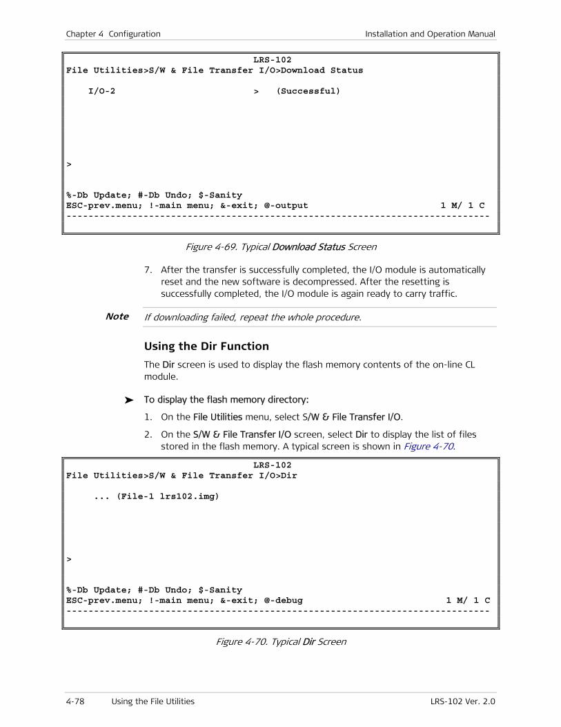
Chapter 4 Configuration Installation and Operation Manual
4-78 Using the File Utilities LRS-102 Ver. 2.0
LRS-102 File Utilities>S/W & File Transfer I/O>Download Status I/O-2 > (Successful) > %-Db Update; #-Db Undo; $-Sanity ESC-prev.menu; !-main menu; &-exit; @-output 1 M/ 1 C -----------------------------------------------------------------------------
Figure 4-69. Typical Download Status Screen
7. After the transfer is successfully completed, the I/O module is automatically reset and the new software is decompressed. After the resetting is successfully completed, the I/O module is again ready to carry traffic.
If downloading failed, repeat the whole procedure.
Using the Dir Function
The Dir screen is used to display the flash memory contents of the on-line CL module.
To display the flash memory directory:
1. On the File Utilities menu, select S/W & File Transfer I/O.
2. On the S/W & File Transfer I/O screen, select Dir to display the list of files stored in the flash memory. A typical screen is shown in Figure 4-70.
LRS-102 File Utilities>S/W & File Transfer I/O>Dir ... (File-1 lrs102.img) > %-Db Update; #-Db Undo; $-Sanity ESC-prev.menu; !-main menu; &-exit; @-debug 1 M/ 1 C -----------------------------------------------------------------------------
Figure 4-70. Typical Dir Screen
Note

Installation and Operation Manual Chapter 4 Configuration
LRS-102 Ver. 2.0 Using the File Utilities 4-79
Deleting Files
The Delete File screen is used to delete a file stored in the flash memory of the on-line CL module.
To delete a file from the flash memory:
1. On the File Utilities menu, select S/W & File Transfer I/O.
2. On the S/W & File Transfer I/O screen, select Delete File to display the file selection screen. A typical Delete File screen is shown in Figure 4-71.
LRS-102 ile Utilities>S/W & File Transfer I/O>Delete File 1. File-1 > Please select item <1 to 1> #-Db Undo ESC-prev.menu; !-main menu; &-exit; @-debug 1 M/ 1 C -----------------------------------------------------------------------------
Figure 4-71. Typical Delete File Screen
3. Select the file to be deleted (File-1 or File-2), and then press <Enter>.
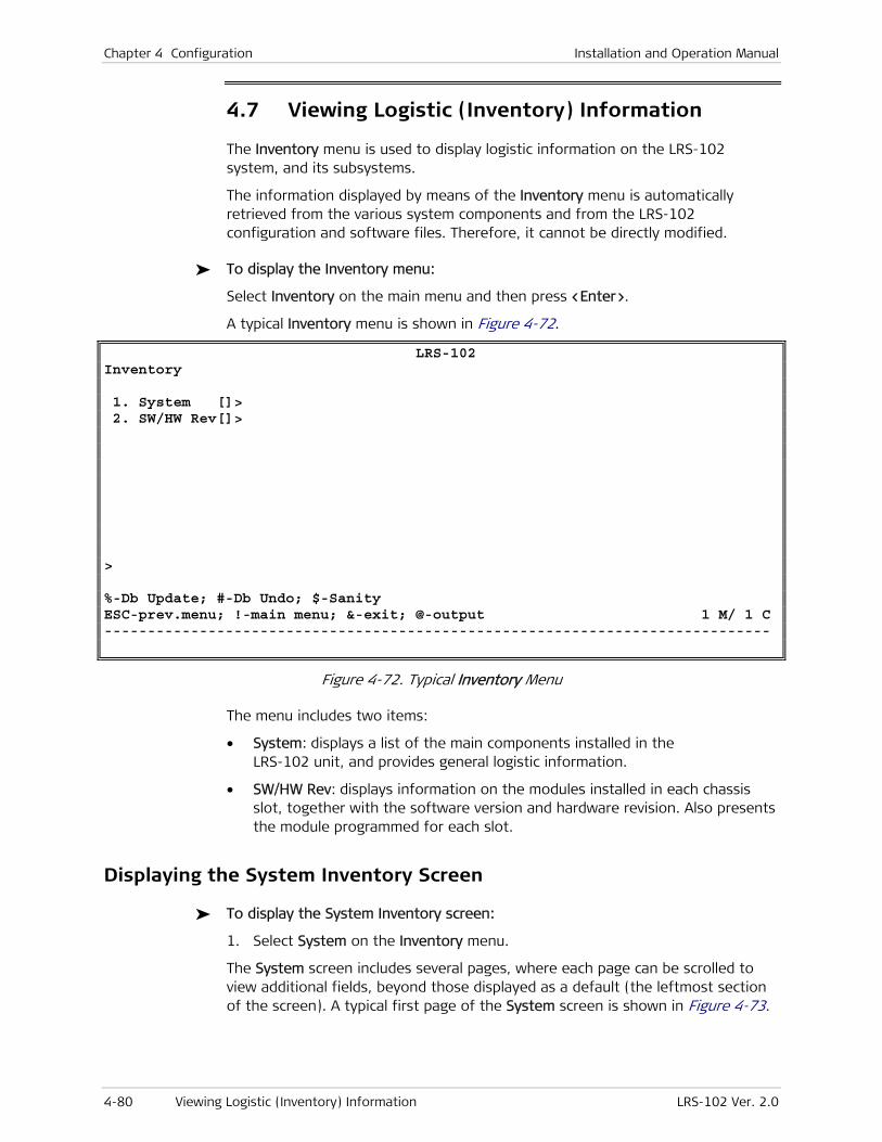
Chapter 4 Configuration Installation and Operation Manual
4-80 Viewing Logistic (Inventory) Information LRS-102 Ver. 2.0
4.7 Viewing Logistic (Inventory) Information
The Inventory menu is used to display logistic information on the LRS-102 system, and its subsystems.
The information displayed by means of the Inventory menu is automatically retrieved from the various system components and from the LRS-102 configuration and software files. Therefore, it cannot be directly modified.
To display the Inventory menu:
Select Inventory on the main menu and then press <Enter>.
A typical Inventory menu is shown in Figure 4-72.
LRS-102 Inventory 1. System []> 2. SW/HW Rev[]> > %-Db Update; #-Db Undo; $-Sanity ESC-prev.menu; !-main menu; &-exit; @-output 1 M/ 1 C -----------------------------------------------------------------------------
Figure 4-72. Typical Inventory Menu
The menu includes two items:
• System: displays a list of the main components installed in the LRS-102 unit, and provides general logistic information.
• SW/HW Rev: displays information on the modules installed in each chassis slot, together with the software version and hardware revision. Also presents the module programmed for each slot.
Displaying the System Inventory Screen
To display the System Inventory screen:
1. Select System on the Inventory menu.
The System screen includes several pages, where each page can be scrolled to view additional fields, beyond those displayed as a default (the leftmost section of the screen). A typical first page of the System screen is shown in Figure 4-73.
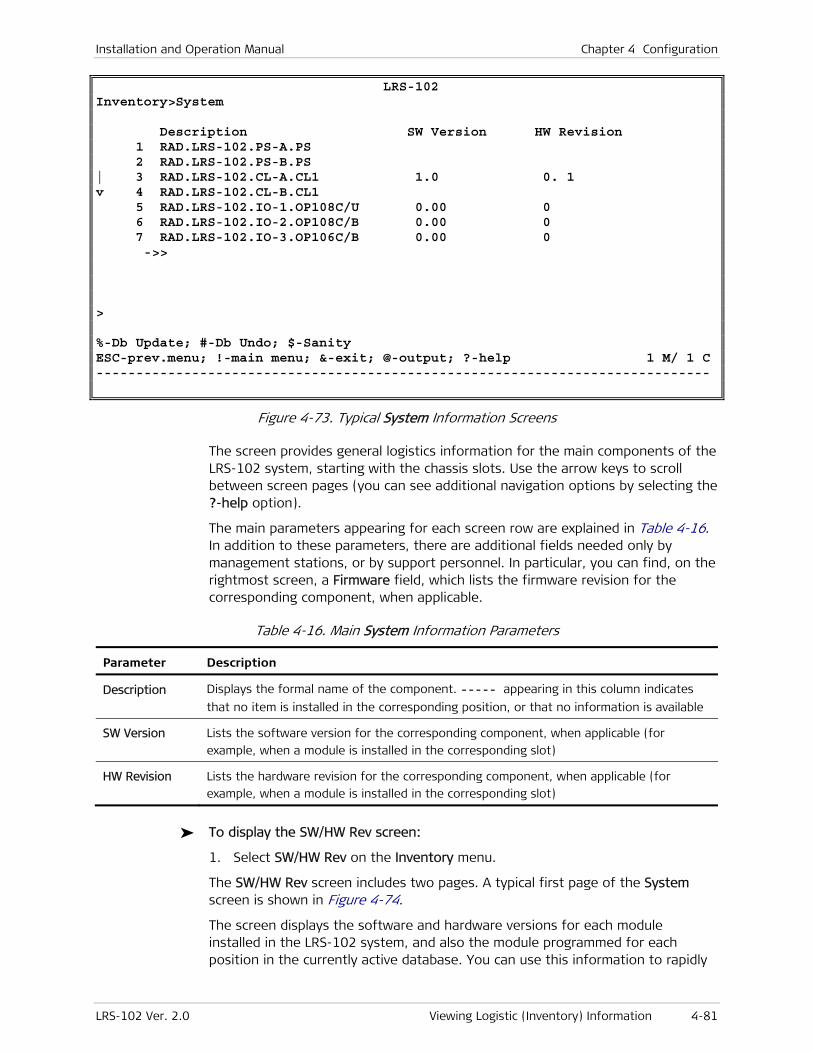
Installation and Operation Manual Chapter 4 Configuration
LRS-102 Ver. 2.0 Viewing Logistic (Inventory) Information 4-81
LRS-102 Inventory>System Description SW Version HW Revision 1 RAD.LRS-102.PS-A.PS 2 RAD.LRS-102.PS-B.PS | 3 RAD.LRS-102.CL-A.CL1 1.0 0. 1 v 4 RAD.LRS-102.CL-B.CL1 5 RAD.LRS-102.IO-1.OP108C/U 0.00 0 6 RAD.LRS-102.IO-2.OP108C/B 0.00 0 7 RAD.LRS-102.IO-3.OP106C/B 0.00 0 ->> > %-Db Update; #-Db Undo; $-Sanity ESC-prev.menu; !-main menu; &-exit; @-output; ?-help 1 M/ 1 C -----------------------------------------------------------------------------
Figure 4-73. Typical System Information Screens
The screen provides general logistics information for the main components of the LRS-102 system, starting with the chassis slots. Use the arrow keys to scroll between screen pages (you can see additional navigation options by selecting the ?-help option).
The main parameters appearing for each screen row are explained in Table 4-16. In addition to these parameters, there are additional fields needed only by management stations, or by support personnel. In particular, you can find, on the rightmost screen, a Firmware field, which lists the firmware revision for the corresponding component, when applicable.
Table 4-16. Main System Information Parameters
Parameter Description
Description Displays the formal name of the component. ----- appearing in this column indicates
that no item is installed in the corresponding position, or that no information is available
SW Version Lists the software version for the corresponding component, when applicable (for
example, when a module is installed in the corresponding slot)
HW Revision Lists the hardware revision for the corresponding component, when applicable (for
example, when a module is installed in the corresponding slot)
To display the SW/HW Rev screen:
1. Select SW/HW Rev on the Inventory menu.
The SW/HW Rev screen includes two pages. A typical first page of the System screen is shown in Figure 4-74.
The screen displays the software and hardware versions for each module installed in the LRS-102 system, and also the module programmed for each position in the currently active database. You can use this information to rapidly

Chapter 4 Configuration Installation and Operation Manual
4-82 Viewing Logistic (Inventory) Information LRS-102 Ver. 2.0
check for inconsistencies between the modules installed in the chassis, and those programmed in the active database.
LRS-102 Inventory>SW/HW rev Slot Installed Card HW Revision SW Version Programmed Card PS-A PS PS PS-B PS PS | CL-A CL1 0. 1 1.0 CL1 v CL-B CL1 CL1 IO-1 OP108C/U 0 0.00 OP108C/U IO-2 OP108C/B 0 0.00 OP108C/B IO-3 OP106C/B 0 0.00 OP106C/B IO-4 ------------- ------------- IO-5 ------------- ------------- IO-6 ------------- ------------- IO-7 ------------- ------------- IO-8 ------------- ------------- > %-Db Update; #-Db Undo; $-Sanity ESC-prev.menu; !-main menu; &-exit; @-output; ?-help 1 M/ 1 C -----------------------------------------------------------------------------
Figure 4-74. Typical SW/HW Rev Screen
The information presented in Figure 4-74 displays logistics data that may be needed by RAD technical support personnel when servicing the unit. The information is retrieved from the modules installed in chassis.
Table 4-17. SW/HW Rev Information Parameters
Parameter Description
Slot Displays the chassis slot designation
Installed Card Lists the module installed in the corresponding chassis slot.
----- in this column indicates that no module is installed in the corresponding slot
HW Revision When a module is installed in the corresponding slot, lists its hardware revision
SW Version When a module is installed in the corresponding slot, lists its software version
Programmed Card Lists the module programmed in the currently active database for the corresponding
chassis slot

LRS-102 Ver. 2.0 Outline of Configuration Sequence 5-1
Chapter 5
Configuring Typical Applications
5.1 Overview
This Chapter provides basic configuration guidelines for LRS-102 systems, which prepare the LRS-102 for use in typical applications.
In addition to the configuration information appearing in this Chapter, it is necessary to configure the I/O modules installed in the chassis in accordance with their Installation and Operation Manuals.
Unless otherwise specified, all the parameter values appearing in the following screens are given for illustration purposes only, for the specific configuration examples presented in this Chapter. They do not reflect recommended values for other operating conditions.
The configuration activities presented in this Chapter assume that LRS-102 is being configured using a standard ASCII terminal, and that you are familiar with the LRS-102 management, as described in Chapter 3. Detailed descriptions and instructions for using each screen identified below appear in Chapter 4.
For your convenience, you can find below an outline of the general configuration sequence.
5.2 Outline of Configuration Sequence
Preliminary Configuration Sequence
The purpose of the preliminary configuration is to prepare the minimal set of parameters needed to manage the LRS-102. In particular, after preliminary configuration you will enable management access by Telnet hosts and Web browsers that are attached to a LAN directly connected to the Ethernet port of the LRS-102 CL module, or at a remote location from which IP communication with the CL module is possible.
The preliminary configuration sequence is presented in Section 3.4.
After completing the preliminary configuration, you may also use Telnet hosts and Web browsers to manage the LRS-102.
Note
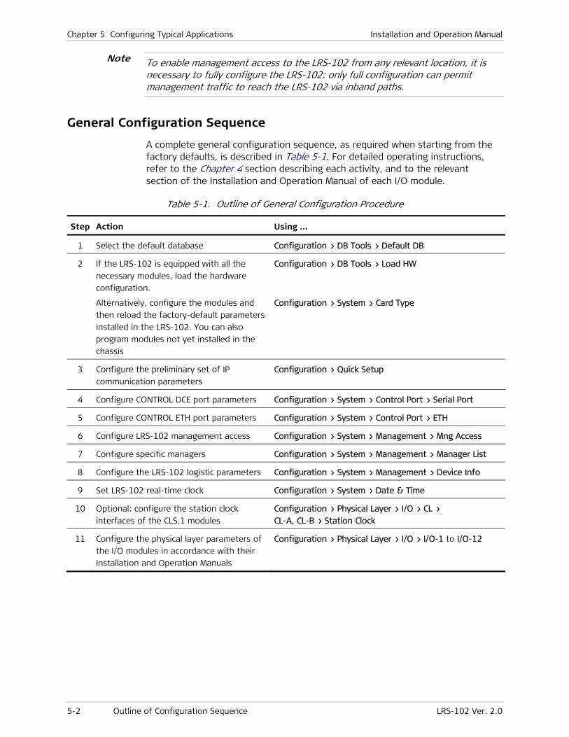
Chapter 5 Configuring Typical Applications Installation and Operation Manual
5-2 Outline of Configuration Sequence LRS-102 Ver. 2.0
To enable management access to the LRS-102 from any relevant location, it is necessary to fully configure the LRS-102: only full configuration can permit management traffic to reach the LRS-102 via inband paths.
General Configuration Sequence
A complete general configuration sequence, as required when starting from the factory defaults, is described in Table 5-1. For detailed operating instructions, refer to the Chapter 4 section describing each activity, and to the relevant section of the Installation and Operation Manual of each I/O module.
Table 5-1. Outline of General Configuration Procedure
Step Action Using …
1 Select the default database Configuration > DB Tools > Default DB
2 If the LRS-102 is equipped with all the
necessary modules, load the hardware
configuration.
Alternatively, configure the modules and
then reload the factory-default parameters
installed in the LRS-102. You can also
program modules not yet installed in the
chassis
Configuration > DB Tools > Load HW
Configuration > System > Card Type
3 Configure the preliminary set of IP
communication parameters
Configuration > Quick Setup
4 Configure CONTROL DCE port parameters Configuration > System > Control Port > Serial Port
5 Configure CONTROL ETH port parameters Configuration > System > Control Port > ETH
6 Configure LRS-102 management access Configuration > System > Management > Mng Access
7 Configure specific managers Configuration > System > Management > Manager List
8 Configure the LRS-102 logistic parameters Configuration > System > Management > Device Info
9 Set LRS-102 real-time clock Configuration > System > Date & Time
10 Optional: configure the station clock
interfaces of the CLS.1 modules
Configuration > Physical Layer > I/O > CL >
CL-A, CL-B > Station Clock
11 Configure the physical layer parameters of
the I/O modules in accordance with their
Installation and Operation Manuals
Configuration > Physical Layer > I/O > I/O-1 to I/O-12
Note

Installation and Operation Manual Chapter 5 Configuring Typical Applications
LRS-102 Ver. 2.0 Outline of Configuration Sequence 5-3
Step Action Using …
12 Prepare the LRS-102 for SNMP
management:
1. Select the SNMP support mode
(enable/disable SNMPv3).
If SNMP support mode is changed, save
to activate the change before
continuing.
2. When SNMPv3 is Disabled, configure
SNMPv1 community names.
3. When SNMPv3 is Enabled, configure
parameters in the following order:
– SNMP Engine ID
– SNMPv3 users
– SNMPv3 target parameters
– SNMPv3 notification tags
– SNMPv3 notification tags
– SNMPv3 target transport parameters
– Configure SNMPv1/SNMPv3 mapping
Configuration > System > Management > SNMPv3
Configuration > System > Management > Host IP
Configuration > System > Management > SNMP Engine ID
Configuration > System > Management > SNMPv3
Setting > Users
Configuration > System > Management > SNMPv3
Setting > Targets & Notify > Target Params
Configuration > System > Management > SNMPv3
Setting > Targets & Notify > Notify
Configuration > System > Management > SNMPv3
Setting > Targets & Notify > Traps
Configuration > System > Management > SNMPv3
Setting > Targets & Notify > Target Address
Configuration > System > Management > SNMPv3
Setting > SNMPv1/v3 Mapping
13 Configure Ethernet traffic flows Configuration > Applications > Ethernet Services > Flows
14 Configure the Ethernet management flow Configuration > System > Management > Flow
15 Configure LRS-102 alarm handling Configuration > System > Alarms Configuration
16 Save the final configuration as a database Configuration > DB Tools > Update DB
17 If necessary, prepare additional databases To start from an existing database, use Configuration >
DB Tools > Load DB. Repeat the relevant steps as needed
to create a new database
Chapter 5 Configuring Typical Applications Installation and Operation Manual
5-4 Outline of Configuration Sequence LRS-102 Ver. 2.0

LRS-102 Ver. 2.0 Monitoring Performance 6-1
Chapter 6
Troubleshooting and Diagnostics
This Chapter describes the LRS-102 monitoring and diagnostic functions. The available functions include:
• Collection of performance monitoring data
• Detection of configuration (sanity) errors
• Alarm and event collection, and reporting of relevant alarms. You can also customize alarm handling
• Diagnostic tests for checking transmission paths and IP connectivity.
These functions can be used to identify problems in the network incorporating LRS-102 units, test the proper operation of each LRS-102 unit, and locate rapidly the cause of the fault: within the LRS-102 itself, in its connections to the network or to a user’s equipment unit, or in the another network component.
In addition to the general LRS-102 functions described in this Chapter, you can find information on the module-specific diagnostic functions in the Installation and Operation Manual of each module.
If you need additional support for this product, see Section 6.6 for technical support information.
6.1 Monitoring Performance
LRS-102 supports two types of monitoring activities:
• System monitoring tasks:
Monitoring the CL module status, and, for CLS.1 modules, the status of the station clock port
Displaying information on remote management agents.
Reading current alarms, and alarms history (see Section 6.3).
• Physical layer monitoring tasks, used to display transmission performance statistics for the LRS-102 ports. The collected data enables the system administrator to monitor the transmission performance, and thus the quality of service provided to users, for statistical purposes. In addition, when problems are reported by users served by LRS-102, the collected data can be used for diagnostic purposes, because it can help identify the source of the problem.

Chapter 6 Troubleshooting and Diagnostics Installation and Operation Manual
6-2 Monitoring Performance LRS-102 Ver. 2.0
The data is continuously collected during equipment operation. For TDM ports, the basic performance data is calculated for each second, and accumulated and displayed over a 15-minute (900 second) interval. The data accumulated within the last 24-hour interval is also stored and displayed.
The selection of the desired type of monitoring activity is made on the Monitoring task selection screen. A typical screen is shown in Figure 6-1.
LRS-102 Monitoring 1. System > 2. Physical Layer > > %-Db Update; #-Db Undo; $-Sanity ESC-prev.menu; !-main menu; &-exit; @-output 1 M/ 1 C -----------------------------------------------------------------------------
Figure 6-1. Monitoring – Task Selection Screen
Overview of Monitoring Menu
Figure 6-2 shows the typical structure of the Monitoring menu.
Monitoring
1. System 2. Physical Layer
System
1. Active Alarms (ON) 2. Active Alarms (ALL) 3. Clear Alarms 4. History Alarms 5. All History Alarms 6. CL Status 7. Remote Agents
History Alarms
All Alarms
Active Alarms (ALL) 1. All Alarms 2. System Alarms 3. Slot Alarms
All Alarms
System Alarms
Slot Alarms
Physical Layer
1. I/O 2. CL
I/O
1. I/O-1 2. I/O-2 3. I/O-3 . . . . .
Depends onInstalled Modules
Remote Agents
CL Status
CL-A
1. Station Clock
CL
1. CL-A 2. CL-B
Station Clock
CLS.1 only
All History Alarms
Figure 6-2. Typical Monitoring Menu Structure

Installation and Operation Manual Chapter 6 Troubleshooting and Diagnostics
LRS-102 Ver. 2.0 Monitoring Performance 6-3
Monitoring the CL Module Status
Use the following procedure to display information on the CL modules installed in the LRS-102, and the system status information.
To display the CL module status:
1. Select CL Status on the Monitoring > System menu, and then press <Enter>.
2. You will see the CL Status screen. A typical CL Status screen is shown in Figure 6-3.
LRS-102 Monitoring>System>CL Status CL-A CL-B System Control Activity ON LINE OFF LINE Test Status OFF OFF Alarm Severity MAJOR OFF Configuration File Usage (%) 7 0 Active DB 1 (in use) -- DB Checksum 0D86 0000 Last DB Update 24/02/2008 11:13:40 00/00/00 00:00:00 CL Temperature (C) 44 0 > %-Db Update; #-Db Undo; $-Sanity ESC-prev.menu; !-main menu; &-exit; @-output; ?-help 1 M/ 1 C -----------------------------------------------------------------------------
Figure 6-3. Typical CL Status Screen
3. The screen displays the following information:
System Control Activity
Displays the state of each CL module used by the system:
• ON LINE – indicates the active (master) module.
• OFF LINE – indicates the standby (slave) module.
• NOT EXISTS – the module is not installed.
Test Status Indicates whether tests are present in the system.
Alarm Severity Indicates the type of the most severe alarm that exists in the system: CRITICAL, MAJOR, MINOR, or EVENT. OFF means that no alarm has been reported.
Configuration File Usage
Displays the percentage of the total capacity of the corresponding CL module flash memory currently assigned to configuration files.
Active DB Displays the database number currently in use.
DB Checksum Displays the database checksum, used to detect corruption.
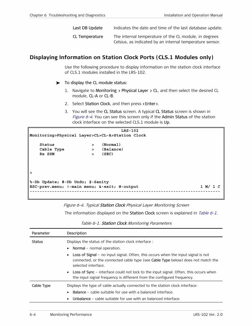
Chapter 6 Troubleshooting and Diagnostics Installation and Operation Manual
6-4 Monitoring Performance LRS-102 Ver. 2.0
Last DB Update Indicates the date and time of the last database update.
CL Temperature The internal temperature of the CL module, in degrees Celsius, as indicated by an internal temperature sensor.
Displaying Information on Station Clock Ports (CLS.1 Modules only)
Use the following procedure to display information on the station clock interface of CLS.1 modules installed in the LRS-102.
To display the CL module status:
1. Navigate to Monitoring > Physical Layer > CL, and then select the desired CL module, CL-A or CL-B.
2. Select Station Clock, and then press <Enter>.
3. You will see the CL Status screen. A typical CL Status screen is shown in Figure 6-4. You can see this screen only if the Admin Status of the station clock interface on the selected CLS.1 module is Up.
LRS-102 Monitoring>Physical Layer>CL>CL-A>Station Clock Status > (Normal) Cable Type > (Balance) Rx SSM > (SEC) > %-Db Update; #-Db Undo; $-Sanity ESC-prev.menu; !-main menu; &-exit; @-output 1 M/ 1 C -----------------------------------------------------------------------------
Figure 6-4. Typical Station Clock Physical Layer Monitoring Screen
The information displayed on the Station Clock screen is explained in Table 6-1.
Table 6-1. Station Clock Monitoring Parameters
Parameter Description
Status Displays the status of the station clock interface :
• Normal – normal operation.
• Loss of Signal – no input signal. Often, this occurs when the input signal is not
connected, or the connected cable type (see Cable Type below) does not match the
selected interface.
• Loss of Sync – interface could not lock to the input signal. Often, this occurs when
the input signal frequency is different from the configured frequency.
Cable Type Displays the type of cable actually connected to the station clock interface:
• Balance – cable suitable for use with a balanced interface.
• Unbalance – cable suitable for use with an balanced interface.
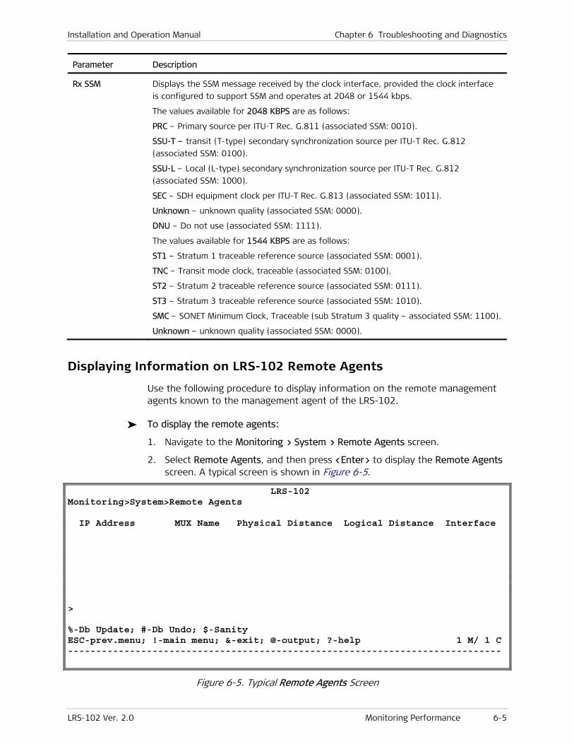
Installation and Operation Manual Chapter 6 Troubleshooting and Diagnostics
LRS-102 Ver. 2.0 Monitoring Performance 6-5
Parameter Description
Rx SSM Displays the SSM message received by the clock interface, provided the clock interface
is configured to support SSM and operates at 2048 or 1544 kbps.
The values available for 2048 KBPS are as follows:
PRC – Primary source per ITU-T Rec. G.811 (associated SSM: 0010).
SSU-T – transit (T-type) secondary synchronization source per ITU-T Rec. G.812
(associated SSM: 0100).
SSU-L – Local (L-type) secondary synchronization source per ITU-T Rec. G.812
(associated SSM: 1000).
SEC – SDH equipment clock per ITU-T Rec. G.813 (associated SSM: 1011).
Unknown – unknown quality (associated SSM: 0000).
DNU – Do not use (associated SSM: 1111).
The values available for 1544 KBPS are as follows:
ST1 – Stratum 1 traceable reference source (associated SSM: 0001).
TNC – Transit mode clock, traceable (associated SSM: 0100).
ST2 – Stratum 2 traceable reference source (associated SSM: 0111).
ST3 – Stratum 3 traceable reference source (associated SSM: 1010).
SMC – SONET Minimum Clock, Traceable (sub Stratum 3 quality – associated SSM: 1100).
Unknown – unknown quality (associated SSM: 0000).
Displaying Information on LRS-102 Remote Agents
Use the following procedure to display information on the remote management agents known to the management agent of the LRS-102.
To display the remote agents:
1. Navigate to the Monitoring > System > Remote Agents screen.
2. Select Remote Agents, and then press <Enter> to display the Remote Agents screen. A typical screen is shown in Figure 6-5.
LRS-102 Monitoring>System>Remote Agents IP Address MUX Name Physical Distance Logical Distance Interface > %-Db Update; #-Db Undo; $-Sanity ESC-prev.menu; !-main menu; &-exit; @-output; ?-help 1 M/ 1 C -----------------------------------------------------------------------------
Figure 6-5. Typical Remote Agents Screen
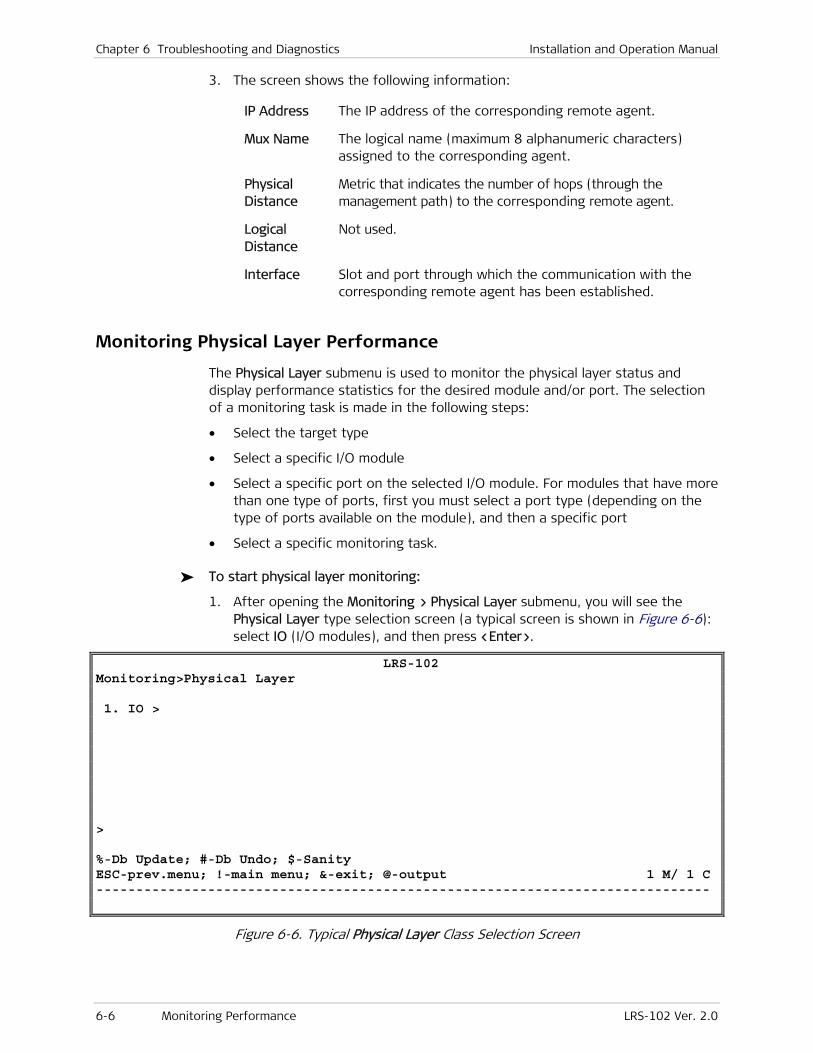
Chapter 6 Troubleshooting and Diagnostics Installation and Operation Manual
6-6 Monitoring Performance LRS-102 Ver. 2.0
3. The screen shows the following information:
IP Address The IP address of the corresponding remote agent.
Mux Name The logical name (maximum 8 alphanumeric characters) assigned to the corresponding agent.
Physical Distance
Metric that indicates the number of hops (through the management path) to the corresponding remote agent.
Logical Distance
Not used.
Interface Slot and port through which the communication with the corresponding remote agent has been established.
Monitoring Physical Layer Performance
The Physical Layer submenu is used to monitor the physical layer status and display performance statistics for the desired module and/or port. The selection of a monitoring task is made in the following steps:
• Select the target type
• Select a specific I/O module
• Select a specific port on the selected I/O module. For modules that have more than one type of ports, first you must select a port type (depending on the type of ports available on the module), and then a specific port
• Select a specific monitoring task.
To start physical layer monitoring:
1. After opening the Monitoring > Physical Layer submenu, you will see the Physical Layer type selection screen (a typical screen is shown in Figure 6-6): select IO (I/O modules), and then press <Enter>.
LRS-102 Monitoring>Physical Layer 1. IO > > %-Db Update; #-Db Undo; $-Sanity ESC-prev.menu; !-main menu; &-exit; @-output 1 M/ 1 C -----------------------------------------------------------------------------
Figure 6-6. Typical Physical Layer Class Selection Screen
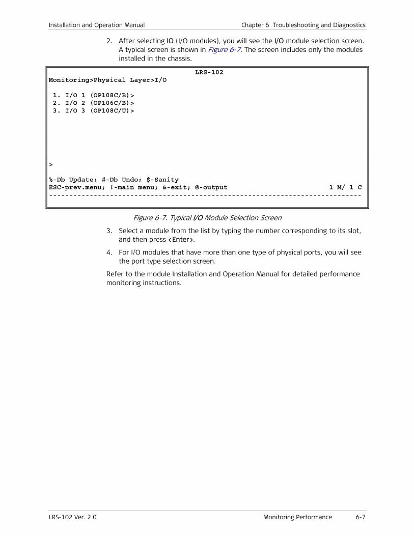
Installation and Operation Manual Chapter 6 Troubleshooting and Diagnostics
LRS-102 Ver. 2.0 Monitoring Performance 6-7
2. After selecting IO (I/O modules), you will see the I/O module selection screen. A typical screen is shown in Figure 6-7. The screen includes only the modules installed in the chassis.
LRS-102 Monitoring>Physical Layer>I/O 1. I/O 1 (OP108C/B)> 2. I/O 2 (OP106C/B)> 3. I/O 3 (OP108C/U)> > %-Db Update; #-Db Undo; $-Sanity ESC-prev.menu; !-main menu; &-exit; @-output 1 M/ 1 C -----------------------------------------------------------------------------
Figure 6-7. Typical I/O Module Selection Screen
3. Select a module from the list by typing the number corresponding to its slot, and then press <Enter>.
4. For I/O modules that have more than one type of physical ports, you will see the port type selection screen.
Refer to the module Installation and Operation Manual for detailed performance monitoring instructions.
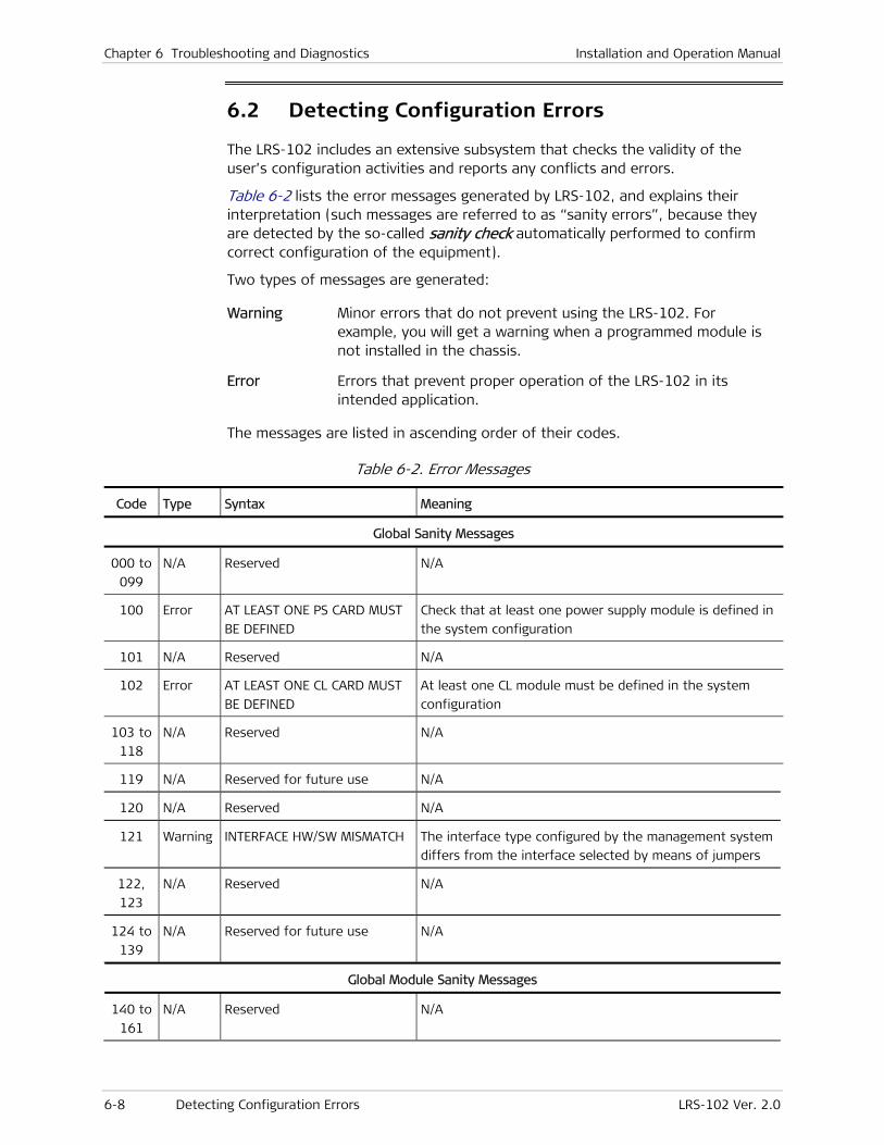
Chapter 6 Troubleshooting and Diagnostics Installation and Operation Manual
6-8 Detecting Configuration Errors LRS-102 Ver. 2.0
6.2 Detecting Configuration Errors
The LRS-102 includes an extensive subsystem that checks the validity of the user’s configuration activities and reports any conflicts and errors.
Table 6-2 lists the error messages generated by LRS-102, and explains their interpretation (such messages are referred to as “sanity errors”, because they are detected by the so-called sanity check automatically performed to confirm correct configuration of the equipment).
Two types of messages are generated:
Warning Minor errors that do not prevent using the LRS-102. For example, you will get a warning when a programmed module is not installed in the chassis.
Error Errors that prevent proper operation of the LRS-102 in its intended application.
The messages are listed in ascending order of their codes.
Table 6-2. Error Messages
Code Type Syntax Meaning
Global Sanity Messages
000 to
099
N/A Reserved N/A
100 Error AT LEAST ONE PS CARD MUST
BE DEFINED
Check that at least one power supply module is defined in
the system configuration
101 N/A Reserved N/A
102 Error AT LEAST ONE CL CARD MUST
BE DEFINED
At least one CL module must be defined in the system
configuration
103 to
118
N/A Reserved N/A
119 N/A Reserved for future use N/A
120 N/A Reserved N/A
121 Warning INTERFACE HW/SW MISMATCH The interface type configured by the management system
differs from the interface selected by means of jumpers
122,
123
N/A Reserved N/A
124 to
139
N/A Reserved for future use N/A
Global Module Sanity Messages
140 to
161
N/A Reserved N/A
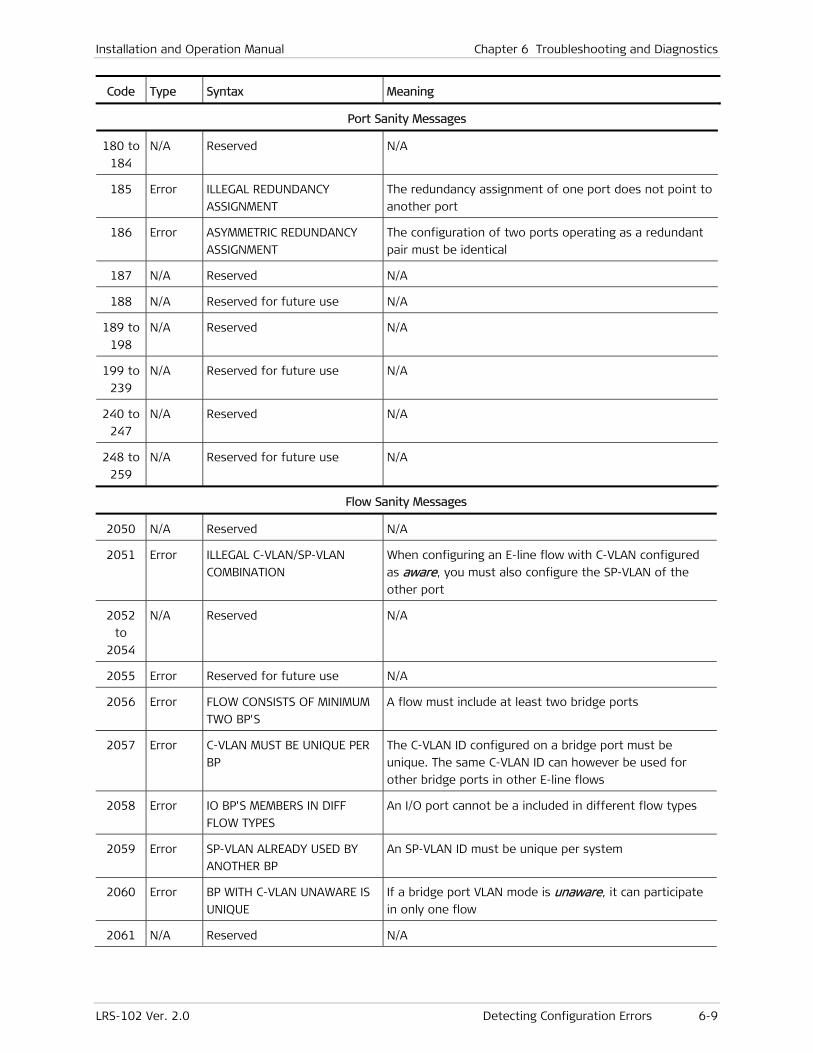
Installation and Operation Manual Chapter 6 Troubleshooting and Diagnostics
LRS-102 Ver. 2.0 Detecting Configuration Errors 6-9
Code Type Syntax Meaning
Port Sanity Messages
180 to
184
N/A Reserved N/A
185 Error ILLEGAL REDUNDANCY
ASSIGNMENT
The redundancy assignment of one port does not point to
another port
186 Error ASYMMETRIC REDUNDANCY
ASSIGNMENT
The configuration of two ports operating as a redundant
pair must be identical
187 N/A Reserved N/A
188 N/A Reserved for future use N/A
189 to
198
N/A Reserved N/A
199 to
239
N/A Reserved for future use N/A
240 to
247
N/A Reserved N/A
248 to
259
N/A Reserved for future use N/A
Flow Sanity Messages
2050 N/A Reserved N/A
2051 Error ILLEGAL C-VLAN/SP-VLAN
COMBINATION
When configuring an E-line flow with C-VLAN configured
as aware, you must also configure the SP-VLAN of the
other port
2052
to
2054
N/A Reserved N/A
2055 Error Reserved for future use N/A
2056 Error FLOW CONSISTS OF MINIMUM
TWO BP'S
A flow must include at least two bridge ports
2057 Error C-VLAN MUST BE UNIQUE PER
BP
The C-VLAN ID configured on a bridge port must be
unique. The same C-VLAN ID can however be used for
other bridge ports in other E-line flows
2058 Error IO BP'S MEMBERS IN DIFF
FLOW TYPES
An I/O port cannot be a included in different flow types
2059 Error SP-VLAN ALREADY USED BY
ANOTHER BP
An SP-VLAN ID must be unique per system
2060 Error BP WITH C-VLAN UNAWARE IS
UNIQUE
If a bridge port VLAN mode is unaware, it can participate
in only one flow
2061 N/A Reserved N/A
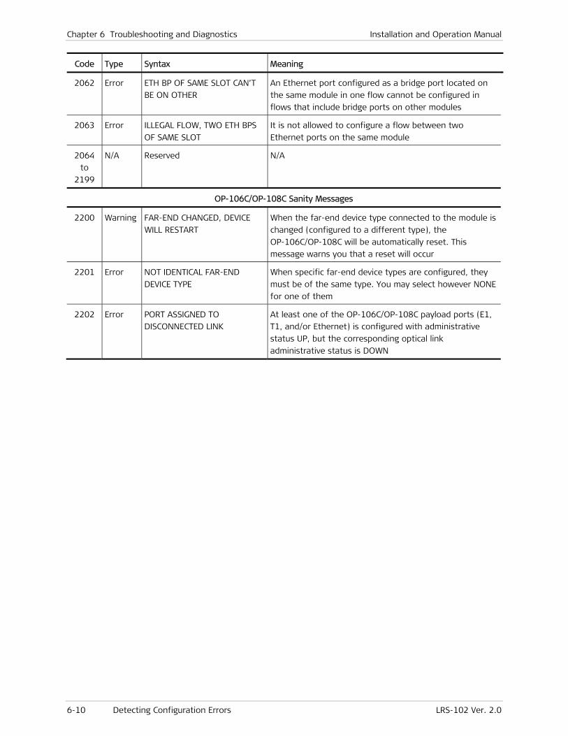
Chapter 6 Troubleshooting and Diagnostics Installation and Operation Manual
6-10 Detecting Configuration Errors LRS-102 Ver. 2.0
Code Type Syntax Meaning
2062 Error ETH BP OF SAME SLOT CAN’T
BE ON OTHER
An Ethernet port configured as a bridge port located on
the same module in one flow cannot be configured in
flows that include bridge ports on other modules
2063 Error ILLEGAL FLOW, TWO ETH BPS
OF SAME SLOT
It is not allowed to configure a flow between two
Ethernet ports on the same module
2064
to
2199
N/A Reserved N/A
OP-106C/OP-108C Sanity Messages
2200 Warning FAR-END CHANGED, DEVICE
WILL RESTART
When the far-end device type connected to the module is
changed (configured to a different type), the
OP-106C/OP-108C will be automatically reset. This
message warns you that a reset will occur
2201 Error NOT IDENTICAL FAR-END
DEVICE TYPE
When specific far-end device types are configured, they
must be of the same type. You may select however NONE
for one of them
2202 Error PORT ASSIGNED TO
DISCONNECTED LINK
At least one of the OP-106C/OP-108C payload ports (E1,
T1, and/or Ethernet) is configured with administrative
status UP, but the corresponding optical link
administrative status is DOWN
Installation and Operation Manual Chapter 6 Troubleshooting and Diagnostics
LRS-102 Ver. 2.0 Handling Alarms and Traps 6-11
6.3 Handling Alarms and Traps
Alarm Collection and Reporting
Alarm Buffer
The LRS-102 continuously monitors critical signals and signal processing functions. In addition, it can also monitor an external alarm line, connected to the ALARM connector.
In case a problem is detected, the LRS-102 generates time-stamped alarm messages. The time stamp is provided by an internal real-time clock.
The alarm messages generated by the LRS-102 are explained below.
Internally, the LRS-102 stores alarms in an alarm buffer. This alarm buffer can store up to 256 alarm messages, together with their time stamps. The alarm history buffer is organized as a FIFO queue, therefore after 256 alarms are written into the buffer, new alarms overwrite the oldest alarms.
Alarm messages can also be automatically sent as traps to the user-specified network management stations.
The alarms can be read on-line by the network administrator using the network management station, a Telnet host, a Web browser or a supervision terminal. The network administrator can then use the various diagnostic tests to determine the causes of the alarm messages and to return the system to normal operation.
When the LRS-102 is powered down, the alarm messages are erased, and therefore old alarms will not reappear after the LRS-102 is powered up again. When using the terminal, a Web browser or a Telnet host, the user also can clear (delete) the alarms stored in this buffer, after reading them.
Alarm Relays
In addition to the alarm collection and reporting facility, the LRS-102 has two alarm relays with floating change-over contacts: one relay for indicating the presence of major alarms and the other for minor alarms. Each relay changes state whenever the first alarm is detected, and returns to its normal state when all the alarms of the corresponding severity disappear.
The relay contacts can be used to report internal system alarms to outside indicators, e.g., lights, buzzers, bells, etc., located on a bay alarm or remote monitoring panel.
Customizing Alarm Handling (Alarm Configuration)
LRS-102 allows to customize alarm handling, and adapt the factory-default alarm indications and reporting capabilities to specific application requirements. During maintenance activities, you can also modify temporarily the alarm reporting criteria, to reduce cluttering by alarms generated during troubleshooting, or as a result of an intentional configuration change, while waiting for service, etc.
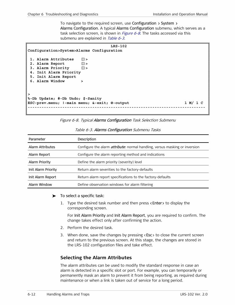
Chapter 6 Troubleshooting and Diagnostics Installation and Operation Manual
6-12 Handling Alarms and Traps LRS-102 Ver. 2.0
To navigate to the required screen, use Configuration > System > Alarms Configuration. A typical Alarms Configuration submenu, which serves as a task selection screen, is shown in Figure 6-8. The tasks accessed via this submenu are explained in Table 6-3.
LRS-102 Configuration>System>Alarms Configuration 1. Alarm Attributes []> 2. Alarm Report []> 3. Alarm Priority []> 4. Init Alarm Priority 5. Init Alarm Report 6. Alarm Window > > %-Db Update; #-Db Undo; $-Sanity ESC-prev.menu; !-main menu; &-exit; @-output 1 M/ 1 C -----------------------------------------------------------------------------
Figure 6-8. Typical Alarms Configuration Task Selection Submenu
Table 6-3. Alarms Configuration Submenu Tasks
Parameter Description
Alarm Attributes Configure the alarm attribute: normal handling, versus masking or inversion
Alarm Report Configure the alarm reporting method and indications
Alarm Priority Define the alarm priority (severity) level
Init Alarm Priority Return alarm severities to the factory-defaults
Init Alarm Report Return alarm report specifications to the factory-defaults
Alarm Window Define observation windows for alarm filtering
To select a specific task:
1. Type the desired task number and then press <Enter> to display the corresponding screen.
For Init Alarm Priority and Init Alarm Report, you are required to confirm. The change takes effect only after confirming the action.
2. Perform the desired task.
3. When done, save the changes by pressing <Esc> to close the current screen and return to the previous screen. At this stage, the changes are stored in the LRS-102 configuration files and take effect.
Selecting the Alarm Attributes
The alarm attributes can be used to modify the standard response in case an alarm is detected in a specific slot or port. For example, you can temporarily or permanently mask an alarm to prevent it from being reporting, as required during maintenance or when a link is taken out of service for a long period.
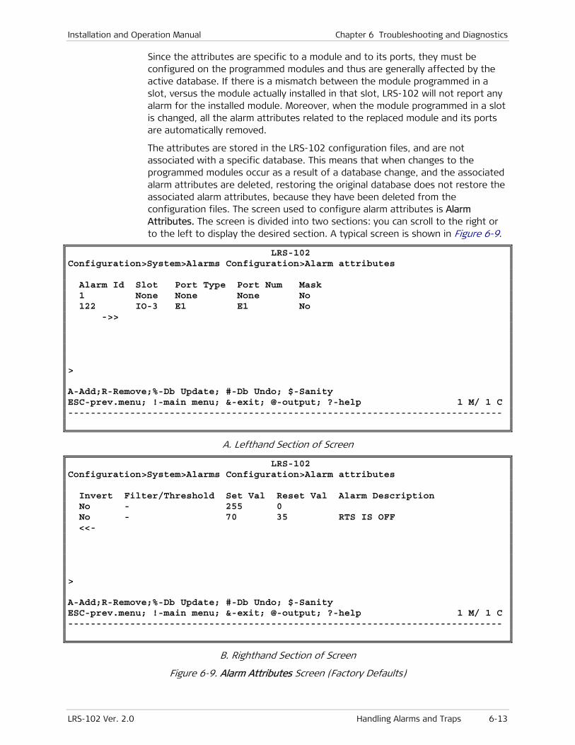
Installation and Operation Manual Chapter 6 Troubleshooting and Diagnostics
LRS-102 Ver. 2.0 Handling Alarms and Traps 6-13
Since the attributes are specific to a module and to its ports, they must be configured on the programmed modules and thus are generally affected by the active database. If there is a mismatch between the module programmed in a slot, versus the module actually installed in that slot, LRS-102 will not report any alarm for the installed module. Moreover, when the module programmed in a slot is changed, all the alarm attributes related to the replaced module and its ports are automatically removed.
The attributes are stored in the LRS-102 configuration files, and are not associated with a specific database. This means that when changes to the programmed modules occur as a result of a database change, and the associated alarm attributes are deleted, restoring the original database does not restore the associated alarm attributes, because they have been deleted from the configuration files. The screen used to configure alarm attributes is Alarm Attributes. The screen is divided into two sections: you can scroll to the right or to the left to display the desired section. A typical screen is shown in Figure 6-9.
LRS-102 Configuration>System>Alarms Configuration>Alarm attributes Alarm Id Slot Port Type Port Num Mask 1 None None None No 122 IO-3 E1 E1 No ->> > A-Add;R-Remove;%-Db Update; #-Db Undo; $-Sanity ESC-prev.menu; !-main menu; &-exit; @-output; ?-help 1 M/ 1 C -----------------------------------------------------------------------------
A. Lefthand Section of Screen
LRS-102 Configuration>System>Alarms Configuration>Alarm attributes Invert Filter/Threshold Set Val Reset Val Alarm Description No - 255 0 No - 70 35 RTS IS OFF <<- > A-Add;R-Remove;%-Db Update; #-Db Undo; $-Sanity ESC-prev.menu; !-main menu; &-exit; @-output; ?-help 1 M/ 1 C -----------------------------------------------------------------------------
B. Righthand Section of Screen
Figure 6-9. Alarm Attributes Screen (Factory Defaults)
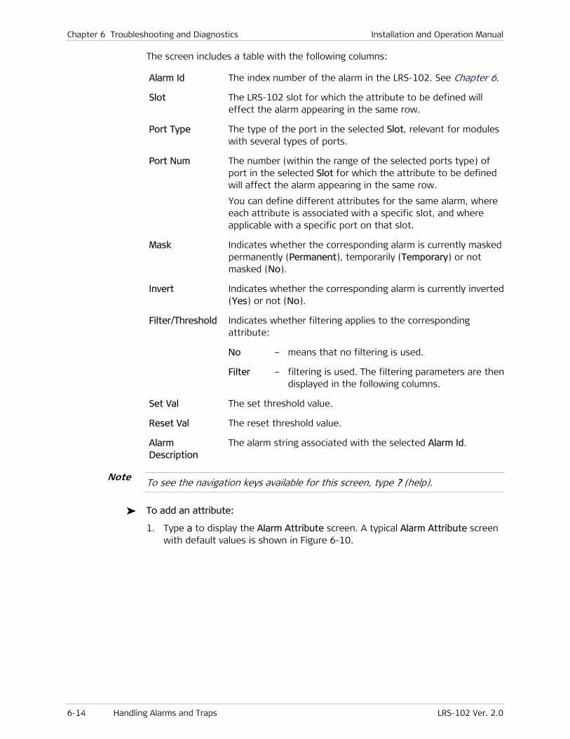
Chapter 6 Troubleshooting and Diagnostics Installation and Operation Manual
6-14 Handling Alarms and Traps LRS-102 Ver. 2.0
The screen includes a table with the following columns:
Alarm Id The index number of the alarm in the LRS-102. See Chapter 6.
Slot The LRS-102 slot for which the attribute to be defined will effect the alarm appearing in the same row.
Port Type The type of the port in the selected Slot, relevant for modules with several types of ports.
Port Num The number (within the range of the selected ports type) of port in the selected Slot for which the attribute to be defined will affect the alarm appearing in the same row.
You can define different attributes for the same alarm, where each attribute is associated with a specific slot, and where applicable with a specific port on that slot.
Mask Indicates whether the corresponding alarm is currently masked permanently (Permanent), temporarily (Temporary) or not masked (No).
Invert Indicates whether the corresponding alarm is currently inverted (Yes) or not (No).
Filter/Threshold Indicates whether filtering applies to the corresponding attribute:
No – means that no filtering is used.
Filter – filtering is used. The filtering parameters are then displayed in the following columns.
Set Val The set threshold value.
Reset Val The reset threshold value.
Alarm Description
The alarm string associated with the selected Alarm Id.
To see the navigation keys available for this screen, type ? (help).
To add an attribute:
1. Type a to display the Alarm Attribute screen. A typical Alarm Attribute screen with default values is shown in Figure 6-10.
Note

Installation and Operation Manual Chapter 6 Troubleshooting and Diagnostics
LRS-102 Ver. 2.0 Handling Alarms and Traps 6-15
LRS-102 Configuration>System>Alarms Configuration>Alarm attributes Set Val[1 - 100] ... (0) Reset Val[1 - 100] ... (0) Alarm Description ... () 1. Alarm Id[1 - 2104] ... (0) 2. Slot > (None) 3. Port Type > (None) 4. Port Num > (None) 5. Mask > (No) 6. Invert > (No) 7. Filter/Threshold > (No) > #-Db Undo; S-Save ESC-prev.menu; !-main menu; &-exit; @-output 1 M/ 1 C -----------------------------------------------------------------------------
Figure 6-10. Typical Alarm Attributes Configuration Screen
2. Use Alarm Id to select the desired alarm. The corresponding alarm description appears in the Alarm Description field. If you need a description of the various alarms, refer to Chapter 5.
3. Select Slot to open the slot selection screen, and then select the slot for which the attribute will be in effect Make sure to select only slots for which modules have already been programmed..
4. Select Port Type to open the port type selection screen for the selected Slot, and then select the desired type of ports. The displayed options depend on the module programmed in the selected slot.
5. Select Port Num to open the port selection screen (only ports of the selected Port Type will be displayed), and then select a specific port for which the attribute will be in effect. Make sure to select a configured port with Admin Status=UP.
You need to define separately the attribute for each required port, even when the attribute applies to the same alarm.
6. Select Mask to open the masking attribute selection screen. You can change the masking attribute by typing the item number for the new attribute, and then pressing <Enter>. To cancel the permanent masking of an alarm, select the Normal attribute.
The meaning of the various masking attributes is as follows:
Normal The alarms are generated in accordance with the conditions defined in Chapter 5, and reported in accordance with the selections made using the Alarm Report screen.
Selecting Normal for an alarm effectively deletes any special masking attribute defined for this alarm.
Note
Chapter 6 Troubleshooting and Diagnostics Installation and Operation Manual
6-16 Handling Alarms and Traps LRS-102 Ver. 2.0
Temporary The alarm is temporarily masked, and therefore if the LRS-102 is reset or is turned off and then back on, the masking is automatically canceled.
A masked alarm does not effect the LRS-102 alarm status. As a result, the various alarm indicators of the LRS-102 will not turn on as a result of a masked alarm, and the generation of the corresponding trap is disabled.
Masking an alarm cancels the Invert attribute, if currently defined for this alarm.
Permanent The alarm is permanently masked: the masking information is stored in the non-volatile memory, and therefore masking is still active after the LRS-102 is reset, or is turned off and then back on.
7. Select Invert to open the inversion attribute selection screen: you can select between No and Yes.
It is not possible to invert event alarms, but only state alarms. A state alarm is an alarm that is in the ON state while a certain condition is present, and automatically changes to OFF when the condition is no longer present. This type of alarm cannot be cleared (removed from the alarm buffer) while it is in the ON state.
Selecting Yes for an alarm cancels the masking attribute, if currently defined for this alarm.
The meaning of the inversion attributes is as follows:
No Normal interpretation of the alarm condition: an alarm is interpreted as being active when the associated condition, is present (true).
Yes The interpretation of a selected alarm condition is inverted with respect to LRS-102 visual indicators and alarm relays.
When the alarm is inverted, the normal condition is the presence of an alarm condition, and the condition that requires alerting is the absence of the alarm state.
For example, when an E1 port is temporarily out of service, the alarm indication related to loss-of-signal on the corresponding port can be inverted. As a result, the general LRS-102 alarm indicators and the port indicator on the E1 module will be turned off as long as the loss-of-signal condition is present, and will turn on when the port returns to normal operation.
The same is true with respect to the alarm relays: if one of the alarm relays is to be activated by that alarm, then inverting the alarm returns the alarm relay to its non-alarm state while the alarm state is present.
Alarm inversion does not effect the state of the alarm recorded in the LRS-102 alarm buffer (the alarm buffer shows the true state).
Note
Installation and Operation Manual Chapter 6 Troubleshooting and Diagnostics
LRS-102 Ver. 2.0 Handling Alarms and Traps 6-17
When alarms are displayed, masked alarms are identified by an M appearing at the righthand side of the alarm line, and inverted alarms are identified by an I.
8. Select Filter/Threshold to open the filtering control screen. The screen includes two options:
No No filtering is used.
Yes Filtering is enabled. This option appears only when the selected alarm is a state alarm.
The purpose of filtering is to reduce the number of alarms generated under marginal conditions, when the alarm changes state often. For this purpose, the system monitors the alarm state during a fixed time window, defined by means of the Alarm Window screen:
• If the alarm is active for a specified fraction of the observation window (the set threshold), the alarm is declared active, and is reported.
• To cancel the alarm condition, it must be found active for a smaller fraction of the observation window (the reset threshold).
Threshold Enable the use of threshold values. This option appears only when the selected alarm is an event alarm.
An event alarm is an alarm that records the occurrence of an event. This type of alarm can be cleared at any time.
The threshold values are used in conjunction with the filtering window defined by means of the Alarm Window screen to determine when to generate an alert because the frequency of the specified events is too high. Alerts generated when the specified threshold is exceeded cannot be masked, even in case the monitored event is masked.
A separately defined threshold is used to cancel the alert when the frequency of the monitored events decreases below that threshold.
For event alarms, select threshold values:
Set Val The minimum number of times the specified alarm must occur during the observation window for the alarm to be declared active. The allowed range is 0 through 100.
Reset Val The maximum number of times the specified alarm must occur during the observation window for the alarm to be declared inactive. The allowed range is 0 through 100, but the number entered in this field must be less than the number entered as the set threshold.
Note
Note

Chapter 6 Troubleshooting and Diagnostics Installation and Operation Manual
6-18 Handling Alarms and Traps LRS-102 Ver. 2.0
For state alarms, select filtering values:
Set Val The minimum percentage of the observation window during which the alarm must remain in the active state to be declared as active. The allowed range is 0 through 100.
Reset Val The maximum percentage of the observation window during which the alarm may remain in the active state to be declared as inactive. The allowed range is 0 through 100, but the number entered in this field must be less than the number entered as the set threshold.
9. After configuring the desired values, the alarm attribute configuration is ended. A typical screen is shown in Figure 6-11.
LRS-102 Configuration>System>Alarms Configuration>Alarm attributes Alarm Description ... (LOST SIGNAL ON E1/T1 LINK ) 1. Alarm Id[1 - 2104] ... (90) 2. Slot > (IO-2 (OP108C/B)) 3. Port Type > (None) 4. Port Num > (None) 5. Mask > (Temporary) 6. Invert > (No) 7. Filter/Threshold > (Yes) 8. Set Val[1 - 100] ... (65) 9. Reset Val[1 - 100] ... (55) > #-Db Undo; S-Save ESC-prev.menu; !-main menu; &-exit; @-output 1 M/ 1 C -----------------------------------------------------------------------------
Figure 6-11. Typical Alarm Attributes Screen (After Parameter Selection)
10. After configuring the desired values, select S – Save. After pressing <ESC>, the new attribute definition appears in the table of the Alarm Attributes screen (Figure 6-9).
11. Repeat the process to configure all the required attributes for all the ports.
Selecting the Alarm Reporting Method
LRS-102 has a factory-default set of reporting rules for alarms. You can change this set, and define different alarm reporting method and indications for each alarm severity (priority) level using the Alarm Report screen.
A typical Alarm Report screen is shown in Figure 6-12. The screen has two pages: use the arrow keys to scroll between screen pages.
To see the navigation keys available for this screen, type ? (help).
Note
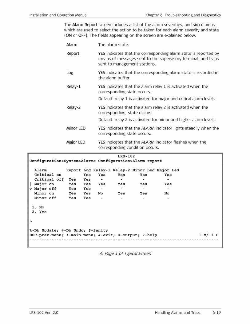
Installation and Operation Manual Chapter 6 Troubleshooting and Diagnostics
LRS-102 Ver. 2.0 Handling Alarms and Traps 6-19
The Alarm Report screen includes a list of the alarm severities, and six columns which are used to select the action to be taken for each alarm severity and state (ON or OFF). The fields appearing on the screen are explained below.
Alarm The alarm state.
Report YES indicates that the corresponding alarm state is reported by means of messages sent to the supervisory terminal, and traps sent to management stations.
Log YES indicates that the corresponding alarm state is recorded in the alarm buffer.
Relay-1 YES indicates that the alarm relay 1 is activated when the corresponding state occurs.
Default: relay 1 is activated for major and critical alarm levels.
Relay-2 YES indicates that the alarm relay 2 is activated when the corresponding state occurs.
Default: relay 2 is activated for minor and higher alarm levels.
Minor LED YES indicates that the ALARM indicator lights steadily when the corresponding state occurs.
Major LED YES indicates that the ALARM indicator flashes when the corresponding condition occurs.
LRS-102 Configuration>System>Alarms Configuration>Alarm report Alarm Report Log Relay-1 Relay-2 Minor Led Major Led Critical on Yes Yes Yes Yes Yes Yes Critical off Yes Yes - - - - | Major on Yes Yes Yes Yes Yes Yes v Major off Yes Yes - - - - Minor on Yes Yes No Yes Yes No Minor off Yes Yes - - - - 1. No 2. Yes > %-Db Update; #-Db Undo; $-Sanity ESC-prev.menu; !-main menu; &-exit; @-output; ?-help 1 M/ 1 C -----------------------------------------------------------------------------
A. Page 1 of Typical Screen
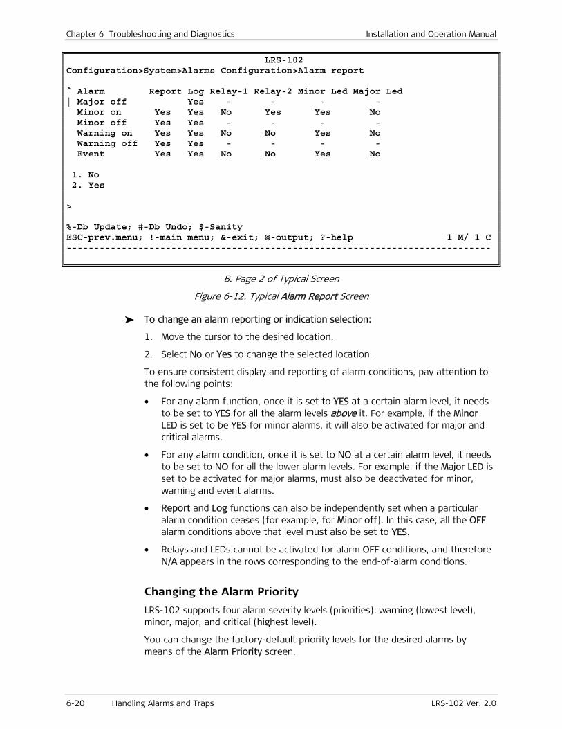
Chapter 6 Troubleshooting and Diagnostics Installation and Operation Manual
6-20 Handling Alarms and Traps LRS-102 Ver. 2.0
LRS-102 Configuration>System>Alarms Configuration>Alarm report ^ Alarm Report Log Relay-1 Relay-2 Minor Led Major Led | Major off Yes Yes - - - - Minor on Yes Yes No Yes Yes No Minor off Yes Yes - - - - Warning on Yes Yes No No Yes No Warning off Yes Yes - - - - Event Yes Yes No No Yes No 1. No 2. Yes > %-Db Update; #-Db Undo; $-Sanity ESC-prev.menu; !-main menu; &-exit; @-output; ?-help 1 M/ 1 C -----------------------------------------------------------------------------
B. Page 2 of Typical Screen
Figure 6-12. Typical Alarm Report Screen
To change an alarm reporting or indication selection:
1. Move the cursor to the desired location.
2. Select No or Yes to change the selected location.
To ensure consistent display and reporting of alarm conditions, pay attention to the following points:
• For any alarm function, once it is set to YES at a certain alarm level, it needs to be set to YES for all the alarm levels above it. For example, if the Minor LED is set to be YES for minor alarms, it will also be activated for major and critical alarms.
• For any alarm condition, once it is set to NO at a certain alarm level, it needs to be set to NO for all the lower alarm levels. For example, if the Major LED is set to be activated for major alarms, must also be deactivated for minor, warning and event alarms.
• Report and Log functions can also be independently set when a particular alarm condition ceases (for example, for Minor off). In this case, all the OFF alarm conditions above that level must also be set to YES.
• Relays and LEDs cannot be activated for alarm OFF conditions, and therefore N/A appears in the rows corresponding to the end-of-alarm conditions.
Changing the Alarm Priority
LRS-102 supports four alarm severity levels (priorities): warning (lowest level), minor, major, and critical (highest level).
You can change the factory-default priority levels for the desired alarms by means of the Alarm Priority screen.
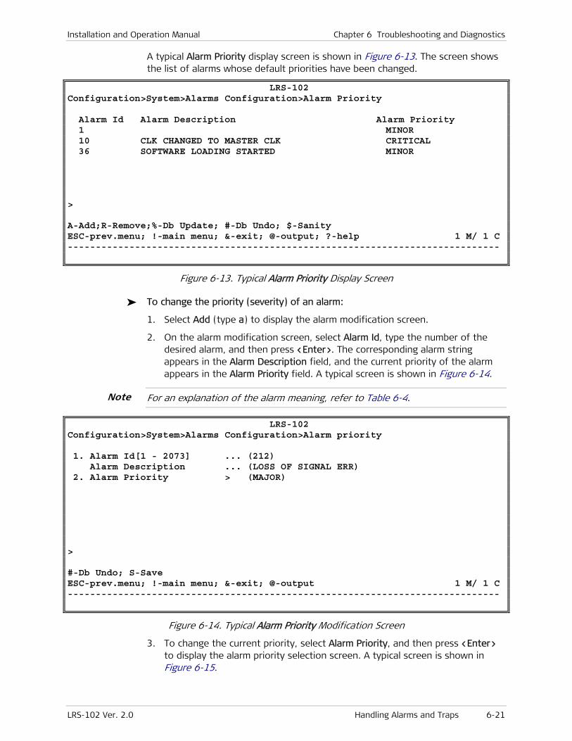
Installation and Operation Manual Chapter 6 Troubleshooting and Diagnostics
LRS-102 Ver. 2.0 Handling Alarms and Traps 6-21
A typical Alarm Priority display screen is shown in Figure 6-13. The screen shows the list of alarms whose default priorities have been changed.
LRS-102 Configuration>System>Alarms Configuration>Alarm Priority Alarm Id Alarm Description Alarm Priority 1 MINOR 10 CLK CHANGED TO MASTER CLK CRITICAL 36 SOFTWARE LOADING STARTED MINOR > A-Add;R-Remove;%-Db Update; #-Db Undo; $-Sanity ESC-prev.menu; !-main menu; &-exit; @-output; ?-help 1 M/ 1 C -----------------------------------------------------------------------------
Figure 6-13. Typical Alarm Priority Display Screen
To change the priority (severity) of an alarm:
1. Select Add (type a) to display the alarm modification screen.
2. On the alarm modification screen, select Alarm Id, type the number of the desired alarm, and then press <Enter>. The corresponding alarm string appears in the Alarm Description field, and the current priority of the alarm appears in the Alarm Priority field. A typical screen is shown in Figure 6-14.
For an explanation of the alarm meaning, refer to Table 6-4.
LRS-102 Configuration>System>Alarms Configuration>Alarm priority 1. Alarm Id[1 - 2073] ... (212) Alarm Description ... (LOSS OF SIGNAL ERR) 2. Alarm Priority > (MAJOR) > #-Db Undo; S-Save ESC-prev.menu; !-main menu; &-exit; @-output 1 M/ 1 C -----------------------------------------------------------------------------
Figure 6-14. Typical Alarm Priority Modification Screen
3. To change the current priority, select Alarm Priority, and then press <Enter> to display the alarm priority selection screen. A typical screen is shown in Figure 6-15.
Note

Chapter 6 Troubleshooting and Diagnostics Installation and Operation Manual
6-22 Handling Alarms and Traps LRS-102 Ver. 2.0
LRS-102 Configuration>System>Alarms Configuration>Alarm Priority 1. WARNING 2. MINOR 3. MAJOR 4. CRITICAL > A-Add;R-Remove;%-Db Update; #-Db Undo; $-Sanity ESC-prev.menu; !-main menu; &-exit; @-output; ?-help 1 M/ 1 C -----------------------------------------------------------------------------
Figure 6-15. Typical Alarm Priority Selection Screen
4. The selection screen offers four options: Warning, Minor, Major, and Critical. Select the desired severity, and then press <Enter>.
5. The updated alarm display appears in the alarm priority display screen.
6. You can repeat Steps 1 to 4 for other alarms, as required.
Selecting the Alarm Threshold Window
LRS-102 uses the alarm Set and Reset values defined by means of the Alarm Attribute Threshold screen, in conjunction with the observation window defined by means of the Alarm Threshold Window screen.
A typical Alarm Threshold Window screen is shown in Figure 6-16.
LRS-102 Configuration>System>Alarms Configuration>Alarm Window 1. Time Window Value (sec)[1 - 255]... (20) > %-Db Update; #-Db Undo; $-Sanity ESC-prev.menu; !-main menu; &-exit; @-output 1 M/ 1 C -----------------------------------------------------------------------------
Figure 6-16. Typical Alarm Threshold Screen
To select the observation window:
1. Select Alarm Window and then enter the desired window duration, in the range of 1 to 255 seconds.
2. When done, press <Enter>.
3. Type % to save and update the database.

Installation and Operation Manual Chapter 6 Troubleshooting and Diagnostics
LRS-102 Ver. 2.0 Handling Alarms and Traps 6-23
Displaying Alarms
To select the type of alarms to be displayed:
1. Open the Monitoring > System submenu.
A typical System task selection submenu is shown in Figure 6-17.
LRS-102 Monitoring>System 1. Active Alarms (ON) []> 2. Active Alarms (ALL)> 3. Clear Alarms 4. Event Log [] 5. CL Status [] 6. Remote Agents [] > %-Db Update; #-Db Undo; $-Sanity ESC-prev.menu; !-main menu; &-exit; @-output 1 M/ 1 C -----------------------------------------------------------------------------
Figure 6-17. Typical System Task Selection Submenu
2. Select one of the following options:
1. To display active alarms, select one of the following:
Active Alarms (ON) – for displaying the currently active (ON) state alarms.
Active Alarms (ALL) – for displaying all the alarms, including events.
2. To display the alarm history (log), select Event Log.
Displaying the Active Alarms in ON State
You can display the currently active state alarms by means of the Active Alarms (ON) item.
• A state alarm is an alarm that is in the ON state while a certain condition is present, and automatically changes to OFF when the condition is no longer present. This type of alarm cannot be cleared (removed from the alarm buffer) while it is in the ON (active) state.
• An event alarm is an alarm that records the occurrence of an event. This type of alarm can be cleared at any time.
Each alarm is displayed in a separate row, which lists from left to right:
• The alarm code
• The module, and where applicable, the port for which the alarm is reported
• The alarm description – a short string that concisely explains the meaning of the alarm code
Note

Chapter 6 Troubleshooting and Diagnostics Installation and Operation Manual
6-24 Handling Alarms and Traps LRS-102 Ver. 2.0
• The alarm severity
• The number of times the alarm occurred
• The masking status of the alarm: an M to the right of the alarm row indicates that the corresponding alarm has been masked.
To display the active alarms (ON):
1. Select Active Alarms (ON) on the Monitoring > System menu, and then press <Enter>.
2. You will see the alarm screen. A typical screen is shown in Figure 6-18.
To see the navigation options for this screen, select the ? (help) option.
LRS-102 Monitoring>System>Active Alarms (ON) B102 Alarm Description (0026)PS-B MODULE TYPE MISMATCH MAJOR 1 M (2021)CL-A CL FAN FAILURE MAJOR 1 | (0026)CL-B MODULE TYPE MISMATCH MAJOR 1 v (2007)IO-1 BUS CLOCK FAILURE MAJOR 1 (0026)IO-2 MODULE TYPE MISMATCH MAJOR 1 (2007)IO-3 BUS CLOCK FAILURE MAJOR 1 (0026)IO-4 MODULE TYPE MISMATCH MAJOR 1 > C-Clear; %-Db Update; #-Db Undo; $-Sanity ESC-prev.menu; !-main menu; &-exit; @-output; ?-help 1 M/ 1 C
Figure 6-18. Typical Active Alarms (ON) Screen
3. You can clear the alarm buffer by typing C (clear). In response, you will see an ALARM BUFFER CLEANED message, and the number of alarms in the history buffer, appearing at the top right-hand corner of the screen, decreases accordingly.
Displaying All the Active Alarms
An alternative display mode for the currently active alarms is the ALL mode, which includes both state alarms and event alarms.
You can display the currently active alarms in three cross-sections:
• All the alarms
• Alarms at the system level
• Alarms related to a specific chassis slot.
In addition, you can mask alarms, and clear the alarm buffer.
Note

Installation and Operation Manual Chapter 6 Troubleshooting and Diagnostics
LRS-102 Ver. 2.0 Handling Alarms and Traps 6-25
To display the active alarms:
1. Select Active Alarms (ALL) on the Monitoring > System menu, and then press <Enter>.
2. You will see the Active Alarms (ALL) type selection screen. A typical screen is shown in Figure 6-19. Next to each option, you can see the highest alarm severity that is currently active.
Where applicable, the highest severity level of the alarms included in the corresponding category is listed in brackets next to each option.
LRS-102 Monitoring>System>Active Alarms (ALL) 1. All Alarms (MAJOR) []> 2. System Alarms (EVENT) []> 3. Slot Alarms > > %-Db Update; #-Db Undo; $-Sanity ESC-prev.menu; !-main menu; &-exit; @-output 1 M/ 1 C -----------------------------------------------------------------------------
Figure 6-19. Typical Active Alarms (ALL) Type Selection Screen
3. Type the desired alarm type number, and then press <Enter>.
To see the navigation options for this screen, select the ? (help) option.
To display all the alarms, or the system alarms:
1. Select All Alarms on the Active Alarms (ALL) type selection screen (Figure 6-19).
A typical screen for the All Alarms selection is shown in Figure 6-20. The System Alarms screen is similar. In most cases, the number of alarms exceeds the maximum that can be displayed on one page, and therefore you may have to scroll down to the page containing the alarm of interest.
2. Each alarm is displayed in a separate row, which lists from left to right:
The alarm code
The module and port for which the alarm is reported
The alarm description – a short string that concisely explains the meaning of the alarm code
The alarm severity
The number of times the alarm occurred.
The screen has an additional field, Alarm Mask, which displays the current attribute of each alarm: No (no mask), Temporary, Permanent.
Note
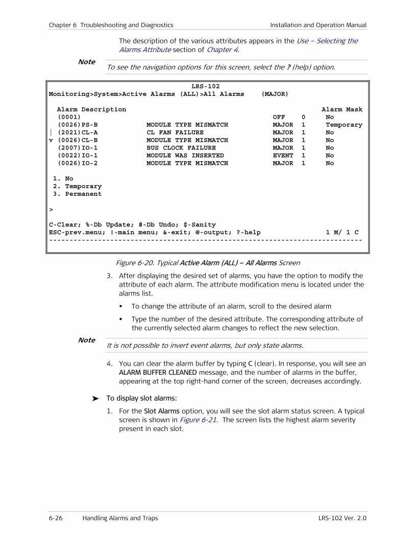
Chapter 6 Troubleshooting and Diagnostics Installation and Operation Manual
6-26 Handling Alarms and Traps LRS-102 Ver. 2.0
The description of the various attributes appears in the Use – Selecting the Alarms Attribute section of Chapter 4.
To see the navigation options for this screen, select the ? (help) option.
LRS-102 Monitoring>System>Active Alarms (ALL)>All Alarms (MAJOR) Alarm Description Alarm Mask (0001) OFF 0 No (0026)PS-B MODULE TYPE MISMATCH MAJOR 1 Temporary | (2021)CL-A CL FAN FAILURE MAJOR 1 No v (0026)CL-B MODULE TYPE MISMATCH MAJOR 1 No (2007)IO-1 BUS CLOCK FAILURE MAJOR 1 No (0022)IO-1 MODULE WAS INSERTED EVENT 1 No (0026)IO-2 MODULE TYPE MISMATCH MAJOR 1 No 1. No 2. Temporary 3. Permanent > C-Clear; %-Db Update; #-Db Undo; $-Sanity ESC-prev.menu; !-main menu; &-exit; @-output; ?-help 1 M/ 1 C -----------------------------------------------------------------------------
Figure 6-20. Typical Active Alarm (ALL) – All Alarms Screen
3. After displaying the desired set of alarms, you have the option to modify the attribute of each alarm. The attribute modification menu is located under the alarms list.
To change the attribute of an alarm, scroll to the desired alarm
Type the number of the desired attribute. The corresponding attribute of the currently selected alarm changes to reflect the new selection.
It is not possible to invert event alarms, but only state alarms.
4. You can clear the alarm buffer by typing C (clear). In response, you will see an ALARM BUFFER CLEANED message, and the number of alarms in the buffer, appearing at the top right-hand corner of the screen, decreases accordingly.
To display slot alarms:
1. For the Slot Alarms option, you will see the slot alarm status screen. A typical screen is shown in Figure 6-21. The screen lists the highest alarm severity present in each slot.
Note
Note
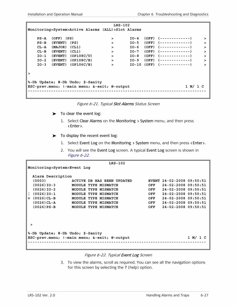
Installation and Operation Manual Chapter 6 Troubleshooting and Diagnostics
LRS-102 Ver. 2.0 Handling Alarms and Traps 6-27
LRS-102 Monitoring>System>Active Alarms (ALL)>Slot Alarms PS-A (OFF) (PS) > IO-4 (OFF) (-------------) > PS-B (EVENT) (PS) > IO-5 (OFF) (-------------) > CL-A (MAJOR) (CL1) > IO-6 (OFF) (-------------) > CL-B (EVENT) (CL1) > IO-7 (OFF) (-------------) > IO-1 (EVENT) (OP108C/U) > IO-8 (OFF) (-------------) > IO-2 (EVENT) (OP108C/B) > IO-9 (OFF) (-------------) > IO-3 (EVENT) (OP106C/B) > IO-10 (OFF) (-------------) > > %-Db Update; #-Db Undo; $-Sanity ESC-prev.menu; !-main menu; &-exit; @-output 1 M/ 1 C -----------------------------------------------------------------------------
Figure 6-21. Typical Slot Alarms Status Screen
To clear the event log:
1. Select Clear Alarms on the Monitoring > System menu, and then press <Enter>.
To display the recent event log:
1. Select Event Log on the Monitoring > System menu, and then press <Enter>.
2. You will see the Event Log screen. A typical Event Log screen is shown in Figure 6-22.
LRS-102 Monitoring>System>Event Log Alarm Description (0003) ACTIVE DB HAS BEEN UPDATED EVENT 24-02-2008 09:50:51 (0026)IO-3 MODULE TYPE MISMATCH OFF 24-02-2008 09:50:51 (0026)IO-2 MODULE TYPE MISMATCH OFF 24-02-2008 09:50:51 | (0026)IO-1 MODULE TYPE MISMATCH OFF 24-02-2008 09:50:51 v (0026)CL-B MODULE TYPE MISMATCH OFF 24-02-2008 09:50:51 (0026)CL-A MODULE TYPE MISMATCH OFF 24-02-2008 09:50:51 (0026)PS-B MODULE TYPE MISMATCH OFF 24-02-2008 09:50:51 > %-Db Update; #-Db Undo; $-Sanity ESC-prev.menu; !-main menu; &-exit; @-output 1 M/ 1 C -----------------------------------------------------------------------------
Figure 6-22. Typical Event Log Screen
3. To view the alarms, scroll as required. You can see all the navigation options for this screen by selecting the ? (help) option.
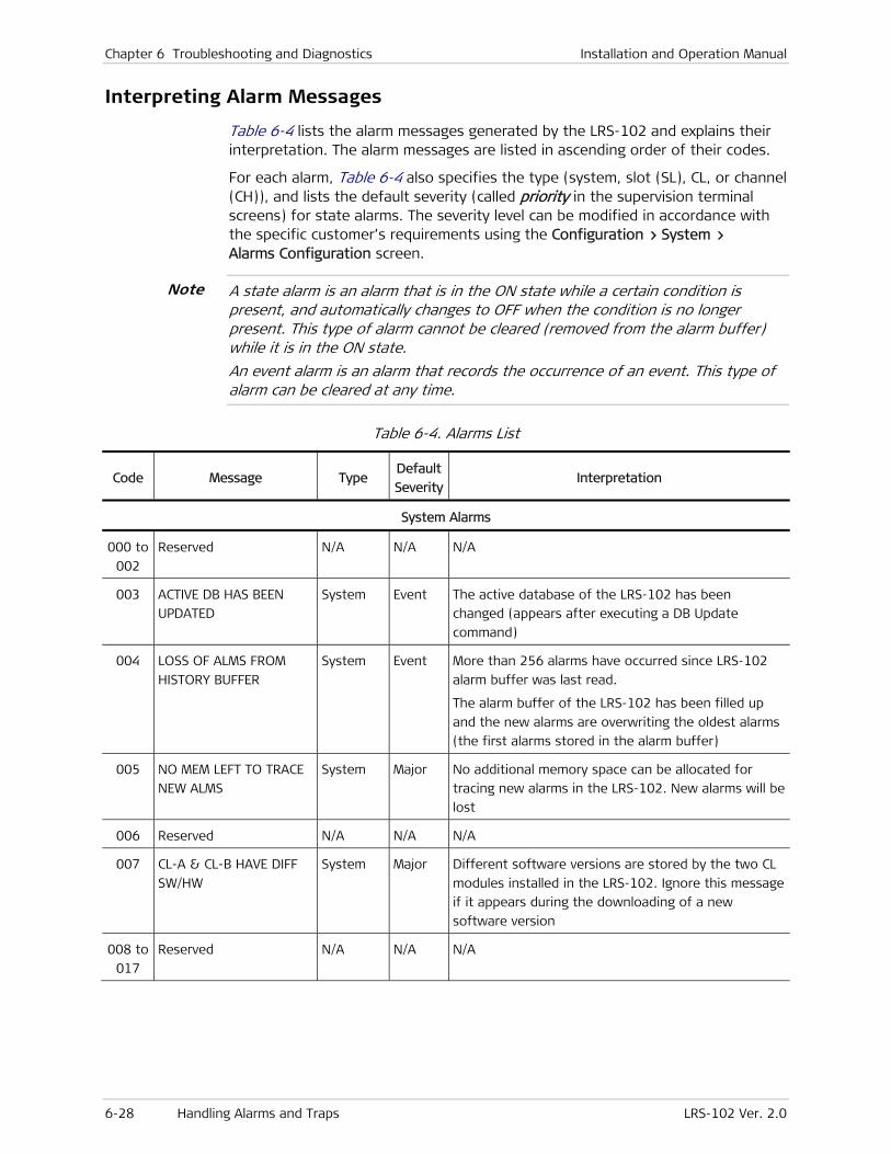
Chapter 6 Troubleshooting and Diagnostics Installation and Operation Manual
6-28 Handling Alarms and Traps LRS-102 Ver. 2.0
Interpreting Alarm Messages
Table 6-4 lists the alarm messages generated by the LRS-102 and explains their interpretation. The alarm messages are listed in ascending order of their codes.
For each alarm, Table 6-4 also specifies the type (system, slot (SL), CL, or channel (CH)), and lists the default severity (called priority in the supervision terminal screens) for state alarms. The severity level can be modified in accordance with the specific customer’s requirements using the Configuration > System > Alarms Configuration screen.
A state alarm is an alarm that is in the ON state while a certain condition is present, and automatically changes to OFF when the condition is no longer present. This type of alarm cannot be cleared (removed from the alarm buffer) while it is in the ON state.
An event alarm is an alarm that records the occurrence of an event. This type of alarm can be cleared at any time.
Table 6-4. Alarms List
Code Message Type Default
SeverityInterpretation
System Alarms
000 to
002
Reserved N/A N/A N/A
003 ACTIVE DB HAS BEEN
UPDATED
System Event The active database of the LRS-102 has been
changed (appears after executing a DB Update
command)
004 LOSS OF ALMS FROM
HISTORY BUFFER
System Event More than 256 alarms have occurred since LRS-102
alarm buffer was last read.
The alarm buffer of the LRS-102 has been filled up
and the new alarms are overwriting the oldest alarms
(the first alarms stored in the alarm buffer)
005 NO MEM LEFT TO TRACE
NEW ALMS
System Major No additional memory space can be allocated for
tracing new alarms in the LRS-102. New alarms will be
lost
006 Reserved N/A N/A N/A
007 CL-A & CL-B HAVE DIFF
SW/HW
System Major Different software versions are stored by the two CL
modules installed in the LRS-102. Ignore this message
if it appears during the downloading of a new
software version
008 to
017
Reserved N/A N/A N/A
Note
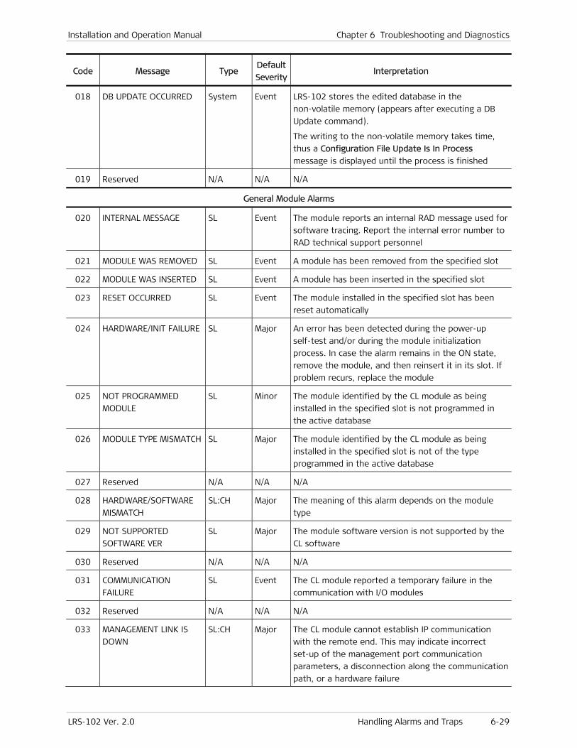
Installation and Operation Manual Chapter 6 Troubleshooting and Diagnostics
LRS-102 Ver. 2.0 Handling Alarms and Traps 6-29
Code Message Type Default
SeverityInterpretation
018 DB UPDATE OCCURRED System Event LRS-102 stores the edited database in the
non-volatile memory (appears after executing a DB
Update command).
The writing to the non-volatile memory takes time,
thus a Configuration File Update Is In Process
message is displayed until the process is finished
019 Reserved N/A N/A N/A
General Module Alarms
020 INTERNAL MESSAGE SL Event The module reports an internal RAD message used for
software tracing. Report the internal error number to
RAD technical support personnel
021 MODULE WAS REMOVED SL Event A module has been removed from the specified slot
022 MODULE WAS INSERTED SL Event A module has been inserted in the specified slot
023 RESET OCCURRED SL Event The module installed in the specified slot has been
reset automatically
024 HARDWARE/INIT FAILURE SL Major An error has been detected during the power-up
self-test and/or during the module initialization
process. In case the alarm remains in the ON state,
remove the module, and then reinsert it in its slot. If
problem recurs, replace the module
025 NOT PROGRAMMED
MODULE
SL Minor The module identified by the CL module as being
installed in the specified slot is not programmed in
the active database
026 MODULE TYPE MISMATCH SL Major The module identified by the CL module as being
installed in the specified slot is not of the type
programmed in the active database
027 Reserved N/A N/A N/A
028 HARDWARE/SOFTWARE
MISMATCH
SL:CH Major The meaning of this alarm depends on the module
type
029 NOT SUPPORTED
SOFTWARE VER
SL Major The module software version is not supported by the
CL software
030 Reserved N/A N/A N/A
031 COMMUNICATION
FAILURE
SL Event The CL module reported a temporary failure in the
communication with I/O modules
032 Reserved N/A N/A N/A
033 MANAGEMENT LINK IS
DOWN
SL:CH Major The CL module cannot establish IP communication
with the remote end. This may indicate incorrect
set-up of the management port communication
parameters, a disconnection along the communication
path, or a hardware failure

Chapter 6 Troubleshooting and Diagnostics Installation and Operation Manual
6-30 Handling Alarms and Traps LRS-102 Ver. 2.0
Code Message Type Default
SeverityInterpretation
034 NOT SUPPORTED
HARDWARE VER
SL Major The module hardware version is not supported by the
CL software
035 Reserved N/A N/A N/A
036 SOFTWARE LOADING
STARTED
SL Event Informative message – indicates that software
downloading using TFTP has been started
037 SOFTWARE LOADING
COMPLETED
SL Event Informative message – indicates that software
downloading has been successfully completed
038 ABORT SOFTWARE
LOADING
SL Event Informative message – indicates that software
downloading has been stopped before its successful
completion
039 Reserved N/A N/A N/A
Power Supply Alarms
040 MAIN VOLTAGE FAIL SL (PS) Major The +5V or +3V voltage is missing. Turn the
LRS-102 off and then on again. If problem recurs,
replace the power supply unit
041 -5V POWER SUPPLY
FAILURE
SL (PS) Major The -5V voltage is missing. Turn the LRS-102 off and
then on again. If problem recurs, replace the power
supply unit
042 12V POWER SUPPLY
FAILURE
SL (PS) Major The 12V voltage is missing. Turn the LRS-102 off and
then on again. If problem recurs, replace the power
supply unit
043 POWER SUPPLY’S FAN
FAILURE
SL (PS) Major The internal cooling fan of the power supply failed.
Replace the module as soon as possible (you can
always replace the module when another PS module
is installed in the chassis)
044 to
049
Reserved for future use N/A N/A N/A
Additional Agent Alarms
050 CL FLIP OCCURRED System Event LRS-102 has switched to the other CL module
051 Reserved for future use N/A N/A N/A
052 to
054
Reserved N/A N/A N/A
055 DBS UPDATED BY TFTP System Event Informative message – indicates that after the
downloading of all the databases is successfully
completed, all the databases have been automatically
updated
056,
057
Reserved N/A N/A N/A
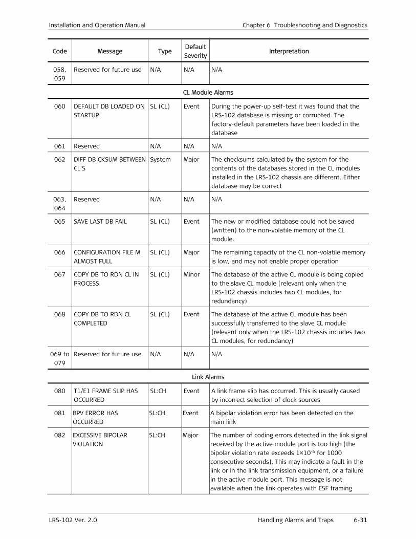
Installation and Operation Manual Chapter 6 Troubleshooting and Diagnostics
LRS-102 Ver. 2.0 Handling Alarms and Traps 6-31
Code Message Type Default
SeverityInterpretation
058,
059
Reserved for future use N/A N/A N/A
CL Module Alarms
060 DEFAULT DB LOADED ON
STARTUP
SL (CL) Event During the power-up self-test it was found that the
LRS-102 database is missing or corrupted. The
factory-default parameters have been loaded in the
database
061 Reserved N/A N/A N/A
062 DIFF DB CKSUM BETWEEN
CL'S
System Major The checksums calculated by the system for the
contents of the databases stored in the CL modules
installed in the LRS-102 chassis are different. Either
database may be correct
063,
064
Reserved N/A N/A N/A
065 SAVE LAST DB FAIL SL (CL) Event The new or modified database could not be saved
(written) to the non-volatile memory of the CL
module.
066 CONFIGURATION FILE M
ALMOST FULL
SL (CL) Major The remaining capacity of the CL non-volatile memory
is low, and may not enable proper operation
067 COPY DB TO RDN CL IN
PROCESS
SL (CL) Minor The database of the active CL module is being copied
to the slave CL module (relevant only when the
LRS-102 chassis includes two CL modules, for
redundancy)
068 COPY DB TO RDN CL
COMPLETED
SL (CL) Event The database of the active CL module has been
successfully transferred to the slave CL module
(relevant only when the LRS-102 chassis includes two
CL modules, for redundancy)
069 to
079
Reserved for future use N/A N/A N/A
Link Alarms
080 T1/E1 FRAME SLIP HAS
OCCURRED
SL:CH Event A link frame slip has occurred. This is usually caused
by incorrect selection of clock sources
081 BPV ERROR HAS
OCCURRED
SL:CH Event A bipolar violation error has been detected on the
main link
082 EXCESSIVE BIPOLAR
VIOLATION
SL:CH Major The number of coding errors detected in the link signal
received by the active module port is too high (the
bipolar violation rate exceeds 1×10⁻⁶ for 1000
consecutive seconds). This may indicate a fault in the
link or in the link transmission equipment, or a failure
in the active module port. This message is not
available when the link operates with ESF framing

Chapter 6 Troubleshooting and Diagnostics Installation and Operation Manual
6-32 Handling Alarms and Traps LRS-102 Ver. 2.0
Code Message Type Default
SeverityInterpretation
083 EXCESSIVE ERROR RATIO SL:CH Major The error rate detected on the frame synchronization
bits is high as defined by ITU-T Rec. G.732. This may
indicate hardware problems or defective connections
(appears only when an E1 link is used)
084 ALARM INDICATION
SIGNAL
SL:CH Major The Alarm Indication Signal (AIS), a framed “all ones”
sequence, is received on the corresponding link
085 AIS RED ALARM SL:CH Major The local frame synchronization has been lost because
of AIS reception
086 LOCAL SYNC LOSS SL:CH Major Local module port lost synchronization to incoming
data stream. May indicate a configuration error or a
technical failure. For T1 links, this condition is the red
alarm
087 REM SYNC LOSS SL:CH Major Remote module port lost synchronization to the
incoming data stream. May indicate a configuration
error or a technical failure. For T1 links, this condition
is the yellow alarm
088 E1 MULTIFRAME LOCAL
SYNC LOSS
SL:CH Minor On an E1 link operating with G732S framing, the
corresponding local module port has lost multiframe
synchronization
089 E1 MULTIFRAME REMOTE
SYNC LOSS
SL:CH Minor On an E1 link operating with G732S framing, the
corresponding remote module port has lost multiframe
synchronization
090 LOST SIGNAL ON E1/T1
MODULE
SL:CH Major The corresponding module port does not receive the
link signal
091 T1/E1 DRIVER FAILURE SL Major Hardware failure on the corresponding module port
(defective transmit line driver)
092 NETWORK LLB SL:CH Minor A network-initiated line loopback has been activated
on the corresponding module port. This loopback
cannot be disconnected by the system management
093 NETWORK PLB SL:CH Minor A network-initiated payload loopback has been
activated. This loopback cannot be disconnected by
the system management. This message may appear
only when using a link with ESF framing
094 CRC ERROR SL:CH Event The corresponding module port reports the detection
of a CRC error. This message may appear only for E1
links using the CRC-4 option
095 AIS WAS DETECTED SL:CH Major The Alarm Indication Signal (AIS), a framed “all ones”
sequence, is received on the corresponding port
096 to
100
Reserved N/A N/A N/A
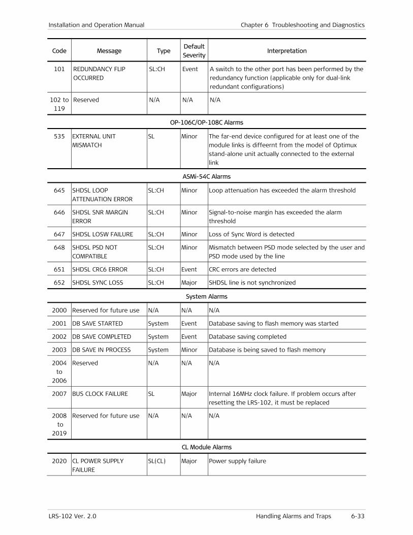
Installation and Operation Manual Chapter 6 Troubleshooting and Diagnostics
LRS-102 Ver. 2.0 Handling Alarms and Traps 6-33
Code Message Type Default
SeverityInterpretation
101 REDUNDANCY FLIP
OCCURRED
SL:CH Event A switch to the other port has been performed by the
redundancy function (applicable only for dual-link
redundant configurations)
102 to
119
Reserved N/A N/A N/A
OP-106C/OP-108C Alarms
535 EXTERNAL UNIT
MISMATCH
SL Minor The far-end device configured for at least one of the
module links is diffeernt from the model of Optimux
stand-alone unit actually connected to the external
link
ASMi-54C Alarms
645 SHDSL LOOP
ATTENUATION ERROR
SL:CH Minor Loop attenuation has exceeded the alarm threshold
646 SHDSL SNR MARGIN
ERROR
SL:CH Minor Signal-to-noise margin has exceeded the alarm
threshold
647 SHDSL LOSW FAILURE SL:CH Minor Loss of Sync Word is detected
648 SHDSL PSD NOT
COMPATIBLE
SL:CH Minor Mismatch between PSD mode selected by the user and
PSD mode used by the line
651 SHDSL CRC6 ERROR SL:CH Event CRC errors are detected
652 SHDSL SYNC LOSS SL:CH Major SHDSL line is not synchronized
System Alarms
2000 Reserved for future use N/A N/A N/A
2001 DB SAVE STARTED System Event Database saving to flash memory was started
2002 DB SAVE COMPLETED System Event Database saving completed
2003 DB SAVE IN PROCESS System Minor Database is being saved to flash memory
2004
to
2006
Reserved N/A N/A N/A
2007 BUS CLOCK FAILURE SL Major Internal 16MHz clock failure. If problem occurs after
resetting the LRS-102, it must be replaced
2008
to
2019
Reserved for future use N/A N/A N/A
CL Module Alarms
2020 CL POWER SUPPLY
FAILURE
SL(CL) Major Power supply failure
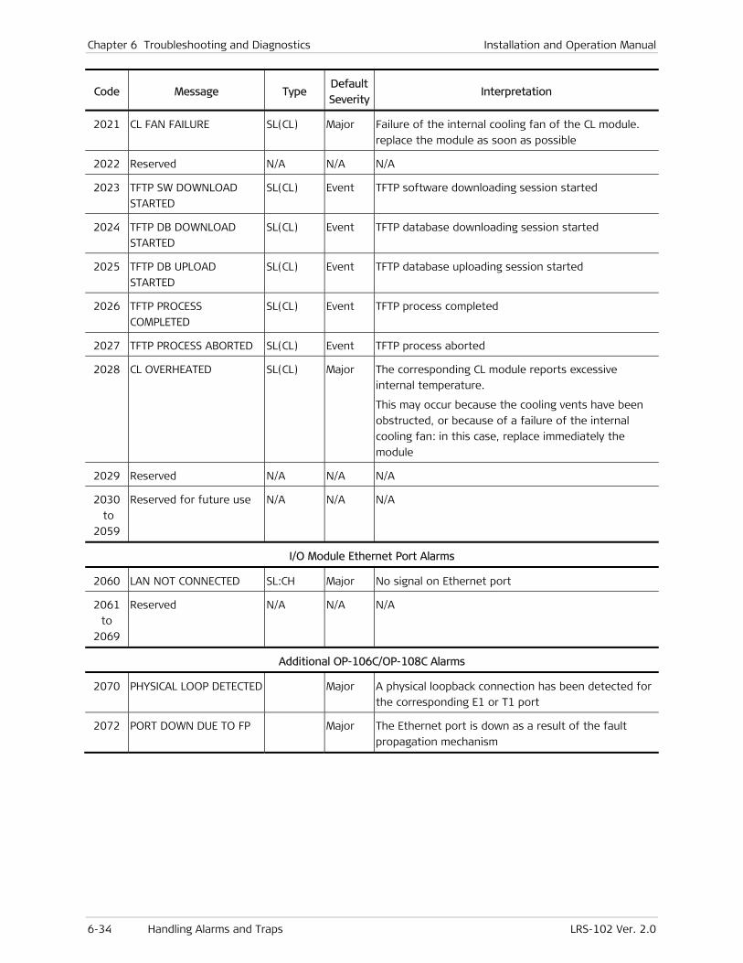
Chapter 6 Troubleshooting and Diagnostics Installation and Operation Manual
6-34 Handling Alarms and Traps LRS-102 Ver. 2.0
Code Message Type Default
SeverityInterpretation
2021 CL FAN FAILURE SL(CL) Major Failure of the internal cooling fan of the CL module.
replace the module as soon as possible
2022 Reserved N/A N/A N/A
2023 TFTP SW DOWNLOAD
STARTED
SL(CL) Event TFTP software downloading session started
2024 TFTP DB DOWNLOAD
STARTED
SL(CL) Event TFTP database downloading session started
2025 TFTP DB UPLOAD
STARTED
SL(CL) Event TFTP database uploading session started
2026 TFTP PROCESS
COMPLETED
SL(CL) Event TFTP process completed
2027 TFTP PROCESS ABORTED SL(CL) Event TFTP process aborted
2028 CL OVERHEATED SL(CL) Major The corresponding CL module reports excessive
internal temperature.
This may occur because the cooling vents have been
obstructed, or because of a failure of the internal
cooling fan: in this case, replace immediately the
module
2029 Reserved N/A N/A N/A
2030
to
2059
Reserved for future use N/A N/A N/A
I/O Module Ethernet Port Alarms
2060 LAN NOT CONNECTED SL:CH Major No signal on Ethernet port
2061
to
2069
Reserved N/A N/A N/A
Additional OP-106C/OP-108C Alarms
2070 PHYSICAL LOOP DETECTED Major A physical loopback connection has been detected for
the corresponding E1 or T1 port
2072 PORT DOWN DUE TO FP Major The Ethernet port is down as a result of the fault
propagation mechanism
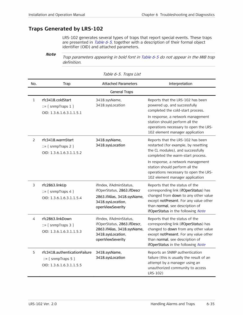
Installation and Operation Manual Chapter 6 Troubleshooting and Diagnostics
LRS-102 Ver. 2.0 Handling Alarms and Traps 6-35
Traps Generated by LRS-102
LRS-102 generates several types of traps that report special events. These traps are presented in Table 6-5, together with a description of their formal object identifier (OID) and attached parameters.
Trap parameters appearing in bold font in Table 6-5 do not appear in the MIB trap definition.
Table 6-5. Traps List
No. Trap Attached Parameters Interpretation
General Traps
1 rfc3418.coldStart
::= { snmpTraps 1 }
OID: 1.3.6.1.6.3.1.1.5.1
3418.sysName,
3418.sysLocation
Reports that the LRS-102 has been
powered up, and successfully
completed the cold-start process.
In response, a network management
station should perform all the
operations necessary to open the LRS-
102 element manager application
2 rfc3418.warmStart
::= { snmpTraps 2 }
OID: 1.3.6.1.6.3.1.1.5.2
3418.sysName,
3418.sysLocation
Reports that the LRS-102 has been
restarted (for example, by resetting
the CL modules), and successfully
completed the warm-start process.
In response, a network management
station should perform all the
operations necessary to open the LRS-
102 element manager application
3 rfc2863.linkUp
::= { snmpTraps 4 }
OID: 1.3.6.1.6.3.1.1.5.4
ifIndex, ifAdminStatus,
ifOperStatus, 2863.ifDescr
2863.ifAlias, 3418.sysName,
3418.sysLocation,
openViewSeverity
Reports that the status of the
corresponding link (ifOperStatus) has
changed from down to any other value
except notPresent. For any value other
than normal, see description of
ifOperStatus in the following Note
4 rfc2863.linkDown
::= { snmpTraps 3 }
OID: 1.3.6.1.6.3.1.1.5.3
ifIndex, ifAdminStatus,
ifOperStatus, 2863.ifDescr,
2863.ifAlias, 3418.sysName,
3418.sysLocation,
openViewSeverity
Reports that the status of the
corresponding link (ifOperStatus) has
changed to down from any other value
except notPresent. For any value other
than normal, see description of
ifOperStatus in the following Note
5 rfc3418.authenticationFailure
::= { snmpTraps 5 }
OID: 1.3.6.1.6.3.1.1.5.5
3418.sysName,
3418.sysLocation
Reports an SNMP authentication
failure (this is usually the result of an
attempt by a manager using an
unauthorized community to access
LRS-102)
Note

Chapter 6 Troubleshooting and Diagnostics Installation and Operation Manual
6-36 Handling Alarms and Traps LRS-102 Ver. 2.0
No. Trap Attached Parameters Interpretation
radGen Traps
6 rad.tftpStatusChangeTrap
OID: 1.3.6.1.4.1.164.6.1.0.1
tftpStatus Reports a change in the status of the
TFTP protocol (used by the RADView
map application SWDL function)
7 rad.agnStatusChangeTrap
::= { systemsEvents 2 }
OID: 1.3.6.1.4.1.164.6.1.0.2
agnIndication,
agnTestStatus,
openViewSeverity (same
value as agnIndication)
Indicates the LRS-102 alarm severity
associated with the reported trap or
event. Used by RADView HPOV map
application to provide the node status
indication (for example, select the
node color on the map)
WAN Traps
8 rad.alarmsTrap
::= { muxHubEvents 1 }
1.3.6.1.4.1.164.3.2.0.1
alrBufDescription,
alrBufCode, alrBufSlot,
alrBufPort, alrBufSeverity,
alrBufState, 3418.sysName,
3418.sysLocation,
openViewSeverity,
2863.ifAlias (only for alarms
related to interfaces)
Provides information on alarms in a
format that includes the information
explained in Table 6-4.
This trap is used by the RADView TDM
Service Center.
9 rad.sanityTrap
::= { muxHubEvents 2 }
1.3.6.1.4.1.164.3.2.0.2
agnSSanityCheckStatus,
agnCSaveCnfgIdxCmd,
mngIP (of the manager that
initiated the Update
command)
Provides information on sanity
warnings and errors detected by the
LRS-102 sanity check function, in a
format that includes the information
explained in Table 6-2
10 rad.cnfgFlipTrap
::= { muxHubEvents 3 }
OID 1.3.6.1.4.1.164.3.2.0.3
agnSActiveCnfg,
mngIP (of the manager that
initiated the Update
command)
Reports that a configuration update,
initiated by the specified manager, is
being performed. A network
management station that detects this
trap should display an Update
Performed message, and should take
steps to avoid errors as a result of the
configuration change (for example,
close windows associated with the
LRS-102 being updated)
11 rad.flipDbChangeTrap
::= { muxHubEvents 4 }
OID: 1.3.6.1.4.1.164.3.2.0.4
agnSAlrStatusAll,
agnSAlrStatus
Reports that a configuration update
has been initiated by an automatic
database flip. This trap is not in use
Installation and Operation Manual Chapter 6 Troubleshooting and Diagnostics
LRS-102 Ver. 2.0 Troubleshooting 6-37
For your convenience, RFC2863 definitions of ifOperStatus are presented below:
• up (1) – If ifAdminStatus is changed to up(1), ifOperStatus will change to up(1) if the interface is ready to transmit and receive network traffic.
• down (2) – If ifAdminStatus is down(2), ifOperStatus must be down(2). If ifAdminStatus is changed to up(1), ifOperStatus should remain in the down(2) state if and only if there is a fault that prevents it from going to the up(1) state. ifOperStatus will change from up(1) to down(2) if the interface cannot pass packets to/from the network.
• testing (3) – A test is active on the interface. The testing(3) state indicates that no operational packets can be passed.
• unknown (4) – Interface status cannot be determined.
• dormant (5) – If ifAdminStatus is changed to up(1), ifOperStatus should change to dormant(5) if the interface is waiting for external actions (such as a serial line waiting for an incoming connection).
• notPresent (6) – Some component is missing. If ifAdminStatus is changed to up(1), ifOperStatus should remain in the notPresent(6) state if the interface has missing (typically, hardware) components.
• lowerLayerDown (7) – The interface is down due to the state of lower-layer interface(s).
6.4 Troubleshooting
Preliminary Checks
In case a problem occurs, perform the following preliminary checks:
• If the problem is detected the first time the LRS-102 is put into operation, first perform the following checks:
Check for proper chassis and module installation, and correct cable connections, in accordance with the system installation plan.
Check the system and module configuration parameters in accordance with the specific application requirements, as provided by the system administrator.
• When two CL modules are installed, check the ON LINE indicators: the ON LINE indicator of the active module must light, and that of the standby must flash. If not, first check the configuration.
• Check the displayed alarm messages and refer to Section 6.3 for their interpretation and associated corrective actions.
Note
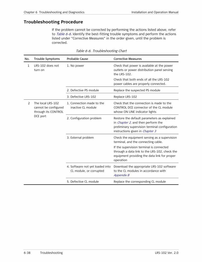
Chapter 6 Troubleshooting and Diagnostics Installation and Operation Manual
6-38 Troubleshooting LRS-102 Ver. 2.0
Troubleshooting Procedure
If the problem cannot be corrected by performing the actions listed above, refer to Table 6-6. Identify the best-fitting trouble symptoms and perform the actions listed under “Corrective Measures” in the order given, until the problem is corrected.
Table 6-6. Troubleshooting Chart
No. Trouble Symptoms Probable Cause Corrective Measures
1 LRS-102 does not
turn on
1. No power Check that power is available at the power
outlets or power distribution panel serving
the LRS-102.
Check that both ends of all the LRS-102
power cables are properly connected.
2. Defective PS module Replace the suspected PS module
3. Defective LRS-102 Replace LRS-102
2 The local LRS-102
cannot be configured
through its CONTROL
DCE port
1. Connection made to the
inactive CL module
Check that the connection is made to the
CONTROL DCE connector of the CL module
whose ON LINE indicator lights
2. Configuration problem Restore the default parameters as explained
in Chapter 2, and then perform the
preliminary supervision terminal configuration
instructions given in Chapter 3
3. External problem Check the equipment serving as a supervision
terminal, and the connecting cable.
If the supervision terminal is connected
through a data link to the LRS-102, check the
equipment providing the data link for proper
operation
4. Software not yet loaded into
CL module, or corrupted
Download the appropriate LRS-102 software
to the CL modules in accordance with
Appendix B
5. Defective CL module Replace the corresponding CL module
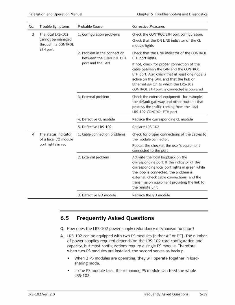
Installation and Operation Manual Chapter 6 Troubleshooting and Diagnostics
LRS-102 Ver. 2.0 Frequently Asked Questions 6-39
No. Trouble Symptoms Probable Cause Corrective Measures
3 The local LRS-102
cannot be managed
through its CONTROL
ETH port
1. Configuration problems Check the CONTROL ETH port configuration.
Check that the ON LINE indicator of the CL
module lights
2. Problem in the connection
between the CONTROL ETH
port and the LAN
Check that the LINK indicator of the CONTROL
ETH port lights.
If not, check for proper connection of the
cable between the LAN and the CONTROL
ETH port. Also check that at least one node is
active on the LAN, and that the hub or
Ethernet switch to which the LRS-102
CONTROL ETH port is connected is powered
3. External problem Check the external equipment (for example,
the default gateway and other routers) that
process the traffic coming from the local
LRS-102 CONTROL ETH port
4. Defective CL module Replace the corresponding CL module
5. Defective LRS-102 Replace LRS-102
4 The status indicator
of a local I/O module
port lights in red
1. Cable connection problems Check for proper connections of the cables to
the module connector.
Repeat the check at the user’s equipment
connected to the port
2. External problem Activate the local loopback on the
corresponding port. If the indicator of the
corresponding local port lights in green while
the loop is connected, the problem is
external. Check cable connections, and the
transmission equipment providing the link to
the remote unit
3. Defective I/O module Replace the I/O module
6.5 Frequently Asked Questions
Q. How does the LRS-102 power supply redundancy mechanism function?
A. LRS-102 can be equipped with two PS modules (either AC or DC). The number of power supplies required depends on the LRS-102 card configuration and capacity, but most configurations require a single PS module. Therefore, when two PS modules are installed, the second serves as backup.
When 2 PS modules are operating, they will operate together in load-sharing mode.
If one PS module fails, the remaining PS module can feed the whole LRS-102.
Chapter 6 Troubleshooting and Diagnostics Installation and Operation Manual
6-40 Frequently Asked Questions LRS-102 Ver. 2.0
You should connect each PS module to a separate power circuit: thus, in case of a power source failure, the other PS module continues receiving power.
Q. How do I connect equipment with an E1 or T1 interface to modules with external E1 or T1 interfaces, for example, OP-108C and OP-106C?
A. LRS-102 modules with external E1 or T1 interfaces use a 44-pin D-type connector. To connect the individual E1 or T1 ports to equipment with RJ-45 connectors, order the following adapter cables:
CBL-G703-8/RJ45: adapter cable terminated in RJ-45 plugs at the user’s end, for use when all the ports are connected to equipment with balanced E1 or T1 interfaces using pins 1, 2 for the receive (RX) pair and pins 4,5 for the transmit (TX) pair
CBL-G703-8/RJ45/X: adapter cable terminated in RJ-45 plugs at the user’s end, for use when all ports are connected to equipment with balanced E1 or T1 interfaces using pins 4,5 for the receive (RX) pair and pins 1, 2 for the transmit (TX) pair
CBL-G703-8/COAX: adapter cable terminated in BNC connectors at the user’s end, for use when all the ports are connected to equipment with unbalanced E1 interfaces
CBL-G703-8/OPEN/2M: adapter cable terminated in free leads at the user’s end. The leads can be connected to any terminal block, or to any connector appropriate for your application. These cables can be used for connection to both balanced and unbalanced interfaces.
Q. What is the difference between the LRS-102 Active Alarms (ON), Active Alarms (ALL), and Event Log screens?
A. Alarm Active (ALL) screen contains all the events and active alarms (along with a brief description) that happened until the last device reset or the last Clear Log command. The alarm status is displayed as a table with the alarm number at the left, followed by the alarm source (for example, slot and port), description, status of the alarm, the number of times the alarm occurred, and an indicator for special conditions (masking or inversion). You can filter the display in accordance with various criteria, for example, source slot or port.
Alarm Active (ON) screen is similar to the Alarm Active (ALL) screen, except that it contains only state alarms in the ON state.
Event Log contains more information than the alarm screens, because each alarm has its own entry. LRS-102 can hold up to 256 entries in the log file, where each entry represent an alarm. The event log is cyclic, meaning after 256 alarms, the old ones are overwritten and the alarm ALARM BUFFER OVERFLOW is added (only once). Each entry (alarm) contains the following information: alarm number, alarm module (I/O slot), port number, description, status (Event, Off, Critical, Major, Minor or Warning), timestamp and date.
Q. How many different configuration databases can the LRS-102 hold?
A. Up to 10 different databases are supported. Switching between databases is done on the fly, without the need for device reset.
Q. How many simultaneous Telnet sessions does LRS-102 support?
A. Up to six.
Installation and Operation Manual Chapter 6 Troubleshooting and Diagnostics
LRS-102 Ver. 2.0 Technical Support 6-41
6.6 Technical Support
Technical support for this product can be obtained from the local distributor from whom it was purchased.
For further information, please contact the RAD distributor nearest you or one of RAD's offices worldwide. This information can be found at www.rad.com (offices – About RAD > Worldwide Offices; distributors – Where to Buy > End Users).

Chapter 6 Troubleshooting and Diagnostics Installation and Operation Manual
6-42 Testing LRS-102 Operation LRS-102 Ver. 2.0
6.7 Testing LRS-102 Operation
When a problem occurs, LRS-102 offers a set of diagnostic functions that permit to efficiently locate the problem (in the LRS-102 chassis, one of LRS-102 modules, a connecting cable, or external equipment) and rapidly restore full service.
The diagnostic functions include:
• Diagnostic tests for checking transmission paths. These tests include loopbacks at the various ports, which enable to identify whether a malfunction is caused by the LRS-102 or by an external system component (for example, an equipment unit, cable, or transmission path connected to the LRS-102).
The available diagnostic functions depend on the installed modules. For specific instructions, refer to the corresponding module Installation and Operation Manual.
• Ping for IP connectivity testing.
Overview of Diagnostics Menu
Figure 6-23 shows the structure of the Diagnostics menu.
Diagnostics
1. Physical Layer 2. Active Tests 3. Ping Test
Physical Layer
1. I/O
Active Tests
Slot Port Test Type Time Out
I/O-1
1. Port 2. Test Type 3. Timeout
I/O
1. I/O-1 2. I/O-2 3. I/O-3 . . . . .
Port 1
1. Link 1 2. Link 2 3. Link 3 4. Link 4 . . . . .
Test Type
Timeout
Ping Test
1. Destination IP Address 2. Number of Frames to Send 3. Send Ping
Figure 6-23. Typical Diagnostics Menu Structure
The Diagnostics menu is used to:
• Enable/disable a test or loopback
• Display the tests and loopbacks that are currently active.
To navigate to the required screen, use Diagnostics.
A typical Diagnostics task selection screen is shown in Figure 6-24.
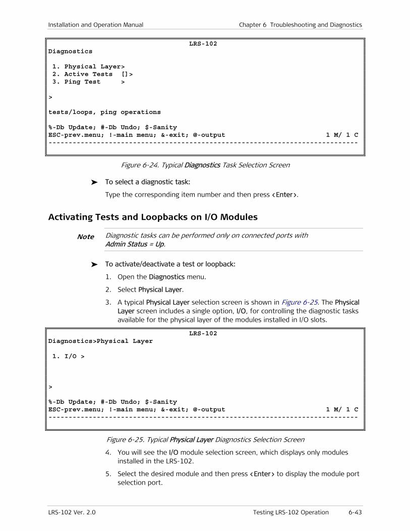
Installation and Operation Manual Chapter 6 Troubleshooting and Diagnostics
LRS-102 Ver. 2.0 Testing LRS-102 Operation 6-43
LRS-102 Diagnostics 1. Physical Layer> 2. Active Tests []> 3. Ping Test > > tests/loops, ping operations %-Db Update; #-Db Undo; $-Sanity ESC-prev.menu; !-main menu; &-exit; @-output 1 M/ 1 C -----------------------------------------------------------------------------
Figure 6-24. Typical Diagnostics Task Selection Screen
To select a diagnostic task:
Type the corresponding item number and then press <Enter>.
Activating Tests and Loopbacks on I/O Modules
Diagnostic tasks can be performed only on connected ports with Admin Status = Up.
To activate/deactivate a test or loopback:
1. Open the Diagnostics menu.
2. Select Physical Layer.
3. A typical Physical Layer selection screen is shown in Figure 6-25. The Physical Layer screen includes a single option, I/O, for controlling the diagnostic tasks available for the physical layer of the modules installed in I/O slots.
LRS-102 Diagnostics>Physical Layer 1. I/O > > %-Db Update; #-Db Undo; $-Sanity ESC-prev.menu; !-main menu; &-exit; @-output 1 M/ 1 C -----------------------------------------------------------------------------
Figure 6-25. Typical Physical Layer Diagnostics Selection Screen
4. You will see the I/O module selection screen, which displays only modules installed in the LRS-102.
5. Select the desired module and then press <Enter> to display the module port selection port.
Note
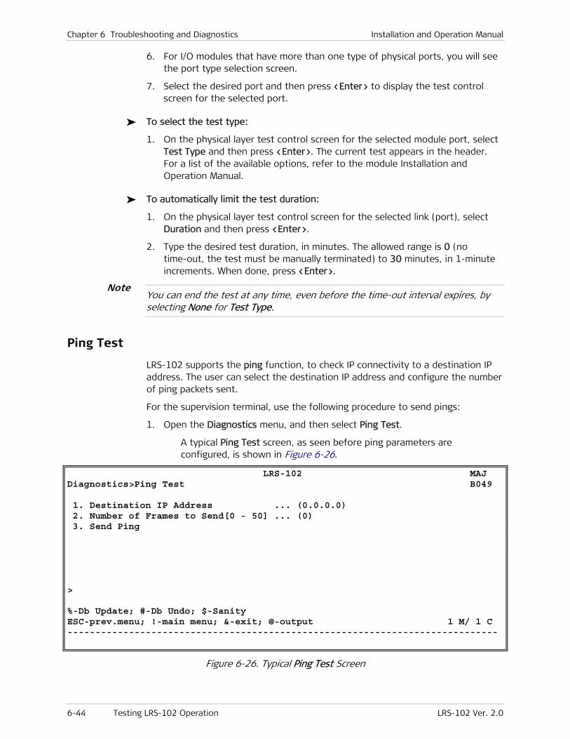
Chapter 6 Troubleshooting and Diagnostics Installation and Operation Manual
6-44 Testing LRS-102 Operation LRS-102 Ver. 2.0
6. For I/O modules that have more than one type of physical ports, you will see the port type selection screen.
7. Select the desired port and then press <Enter> to display the test control screen for the selected port.
To select the test type:
1. On the physical layer test control screen for the selected module port, select Test Type and then press <Enter>. The current test appears in the header. For a list of the available options, refer to the module Installation and Operation Manual.
To automatically limit the test duration:
1. On the physical layer test control screen for the selected link (port), select Duration and then press <Enter>.
2. Type the desired test duration, in minutes. The allowed range is 0 (no time-out, the test must be manually terminated) to 30 minutes, in 1-minute increments. When done, press <Enter>.
You can end the test at any time, even before the time-out interval expires, by selecting None for Test Type.
Ping Test
LRS-102 supports the ping function, to check IP connectivity to a destination IP address. The user can select the destination IP address and configure the number of ping packets sent.
For the supervision terminal, use the following procedure to send pings:
1. Open the Diagnostics menu, and then select Ping Test.
A typical Ping Test screen, as seen before ping parameters are configured, is shown in Figure 6-26.
LRS-102 MAJ Diagnostics>Ping Test B049 1. Destination IP Address ... (0.0.0.0) 2. Number of Frames to Send[0 - 50] ... (0) 3. Send Ping > %-Db Update; #-Db Undo; $-Sanity ESC-prev.menu; !-main menu; &-exit; @-output 1 M/ 1 C -----------------------------------------------------------------------------
Figure 6-26. Typical Ping Test Screen
Note

Installation and Operation Manual Chapter 6 Troubleshooting and Diagnostics
LRS-102 Ver. 2.0 Testing LRS-102 Operation 6-45
2. On the Ping Test screen, select the following parameters:
The desired destination IP address
The number of ping packets (up to 50) to be sent. Pinging will be automatically stopped after sending the specified number of ping packets.
3. To start ping sending, select Send Ping, and then press <Enter>.
4. The prompt area at the bottom of the screen starts displaying the results of each ping packet. After the selected number of packets, you will see the test summary, which indicates:
The number of ping packets sent
The number of ping packets received
The number of lost ping packets (packets not answered before the standard time-out interval expires).
Displaying the Active Tests
You can display the currently active tests using the Diagnostics > Active Tests item.
The active tests are presented in a table that includes the following columns:
• Slot and port on which a test is active
• The test type
• The time-out interval.

Chapter 6 Troubleshooting and Diagnostics Installation and Operation Manual
6-46 Testing LRS-102 Operation LRS-102 Ver. 2.0

LRS-102 Ver. 2.0 CONTROL DCE Connector A-1
Appendix A
Connection Data
A.1 CONTROL DCE Connector
Connector Data
The CONTROL DCE connector is a 9-pin D-type female connector with RS-232 asynchronous DCE interface, intended for direct connection to a supervision terminal. The connector is wired in accordance with Table A-1.
Table A-1. CONTROL DCE Connector Wiring
Pin Function Direction
1 Data Carrier Detect (DCD) From LRS-102
2 Receive Data (RD) From LRS-102
3 Transmit Data (TD) To LRS-102
4 Data Terminal Ready (DTR) To LRS-102
5 Signal Ground (SIG) Common reference and DC power supply ground
6 Data Set Ready (DSR) From LRS-102
7 Request to Send (RTS) To LRS-102
8 Clear to Send (CTS) From LRS-102
9 Ring Indicator (RI) To LRS-102
Connection Data
The connections to the CONTROL DCE connector are made as follows:
• Connection to supervision terminal with 9-pin connector: by means of a straight cable (a cable wired point-to-point).
• Connection to supervision terminal with 25-pin connector: by means of a cable wired in accordance with Figure A-1.
• Connection to modem with 25-pin connector (for communication with remote supervision terminal): by means of a cable wired in accordance with Figure A-1
• Connection to modem with 9-pin connector (for communication with remote supervision terminal): by means of a crossed cable wired in accordance with Figure A-2.
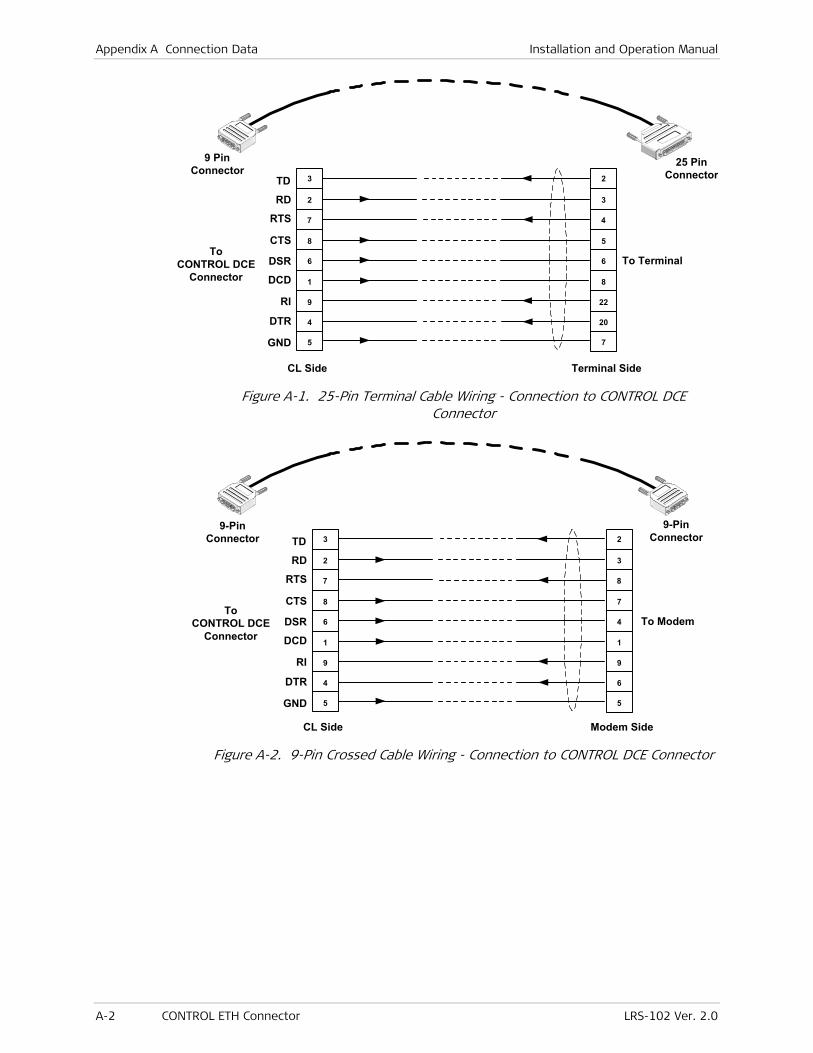
Appendix A Connection Data Installation and Operation Manual
A-2 CONTROL ETH Connector LRS-102 Ver. 2.0
To TerminalTo
CONTROL DCEConnector
CL Side Terminal Side
TD
RTS
CTS
DSR
DCD
RI
DTR
GND
RD
3
2
7
8
6
1
9
4
5
2
3
4
5
6
8
22
20
7
25 PinConnector
9 PinConnector
Figure A-1. 25-Pin Terminal Cable Wiring - Connection to CONTROL DCE Connector
To Modem
Modem Side
TD
RTS
CTS
DSR
DCD
RI
DTR
GND
RD
3
2
7
8
6
1
9
4
5
2
3
8
7
4
1
9
6
5
9-PinConnector
9-PinConnector
ToCONTROL DCE
Connector
CL Side
Figure A-2. 9-Pin Crossed Cable Wiring - Connection to CONTROL DCE Connector
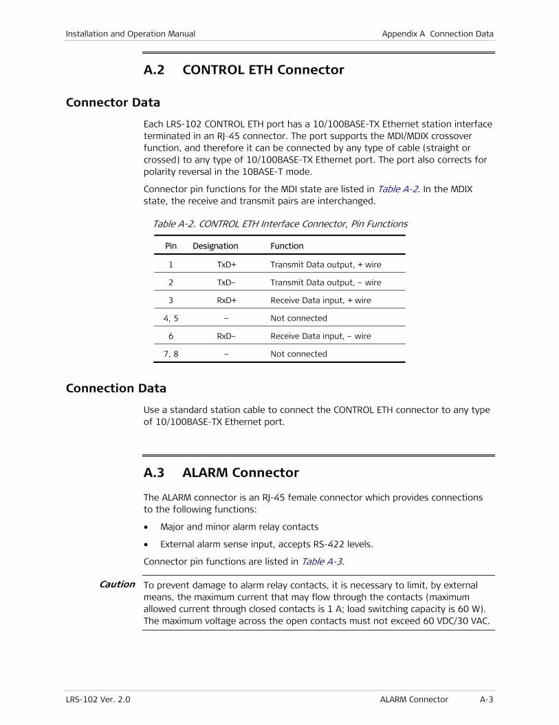
Installation and Operation Manual Appendix A Connection Data
LRS-102 Ver. 2.0 ALARM Connector A-3
A.2 CONTROL ETH Connector
Connector Data
Each LRS-102 CONTROL ETH port has a 10/100BASE-TX Ethernet station interface terminated in an RJ-45 connector. The port supports the MDI/MDIX crossover function, and therefore it can be connected by any type of cable (straight or crossed) to any type of 10/100BASE-TX Ethernet port. The port also corrects for polarity reversal in the 10BASE-T mode.
Connector pin functions for the MDI state are listed in Table A-2. In the MDIX state, the receive and transmit pairs are interchanged.
Table A-2. CONTROL ETH Interface Connector, Pin Functions
Pin Designation Function
1 TxD+ Transmit Data output, + wire
2 TxD– Transmit Data output, – wire
3 RxD+ Receive Data input, + wire
4, 5 – Not connected
6 RxD– Receive Data input, – wire
7, 8 – Not connected
Connection Data
Use a standard station cable to connect the CONTROL ETH connector to any type of 10/100BASE-TX Ethernet port.
A.3 ALARM Connector
The ALARM connector is an RJ-45 female connector which provides connections to the following functions:
• Major and minor alarm relay contacts
• External alarm sense input, accepts RS-422 levels.
Connector pin functions are listed in Table A-3.
To prevent damage to alarm relay contacts, it is necessary to limit, by external means, the maximum current that may flow through the contacts (maximum allowed current through closed contacts is 1 A; load switching capacity is 60 W). The maximum voltage across the open contacts must not exceed 60 VDC/30 VAC.
Caution
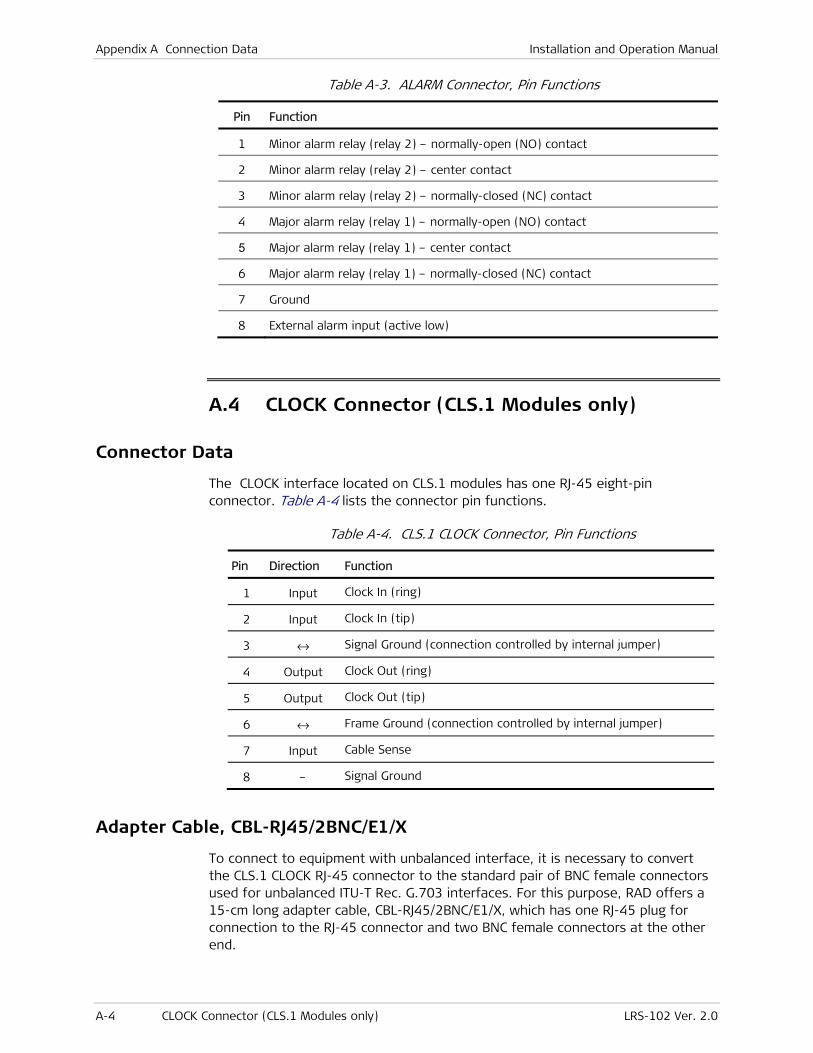
Appendix A Connection Data Installation and Operation Manual
A-4 CLOCK Connector (CLS.1 Modules only) LRS-102 Ver. 2.0
Table A-3. ALARM Connector, Pin Functions
Pin Function
1 Minor alarm relay (relay 2) – normally-open (NO) contact
2 Minor alarm relay (relay 2) – center contact
3 Minor alarm relay (relay 2) – normally-closed (NC) contact
4 Major alarm relay (relay 1) – normally-open (NO) contact
5 Major alarm relay (relay 1) – center contact
6 Major alarm relay (relay 1) – normally-closed (NC) contact
7 Ground
8 External alarm input (active low)
A.4 CLOCK Connector (CLS.1 Modules only)
Connector Data
The CLOCK interface located on CLS.1 modules has one RJ-45 eight-pin connector. Table A-4 lists the connector pin functions.
Table A-4. CLS.1 CLOCK Connector, Pin Functions
Pin Direction Function
1 Input Clock In (ring)
2 Input Clock In (tip)
3 ↔ Signal Ground (connection controlled by internal jumper)
4 Output Clock Out (ring)
5 Output Clock Out (tip)
6 ↔ Frame Ground (connection controlled by internal jumper)
7 Input Cable Sense
8 – Signal Ground
Adapter Cable, CBL-RJ45/2BNC/E1/X
To connect to equipment with unbalanced interface, it is necessary to convert the CLS.1 CLOCK RJ-45 connector to the standard pair of BNC female connectors used for unbalanced ITU-T Rec. G.703 interfaces. For this purpose, RAD offers a 15-cm long adapter cable, CBL-RJ45/2BNC/E1/X, which has one RJ-45 plug for connection to the RJ-45 connector and two BNC female connectors at the other end.
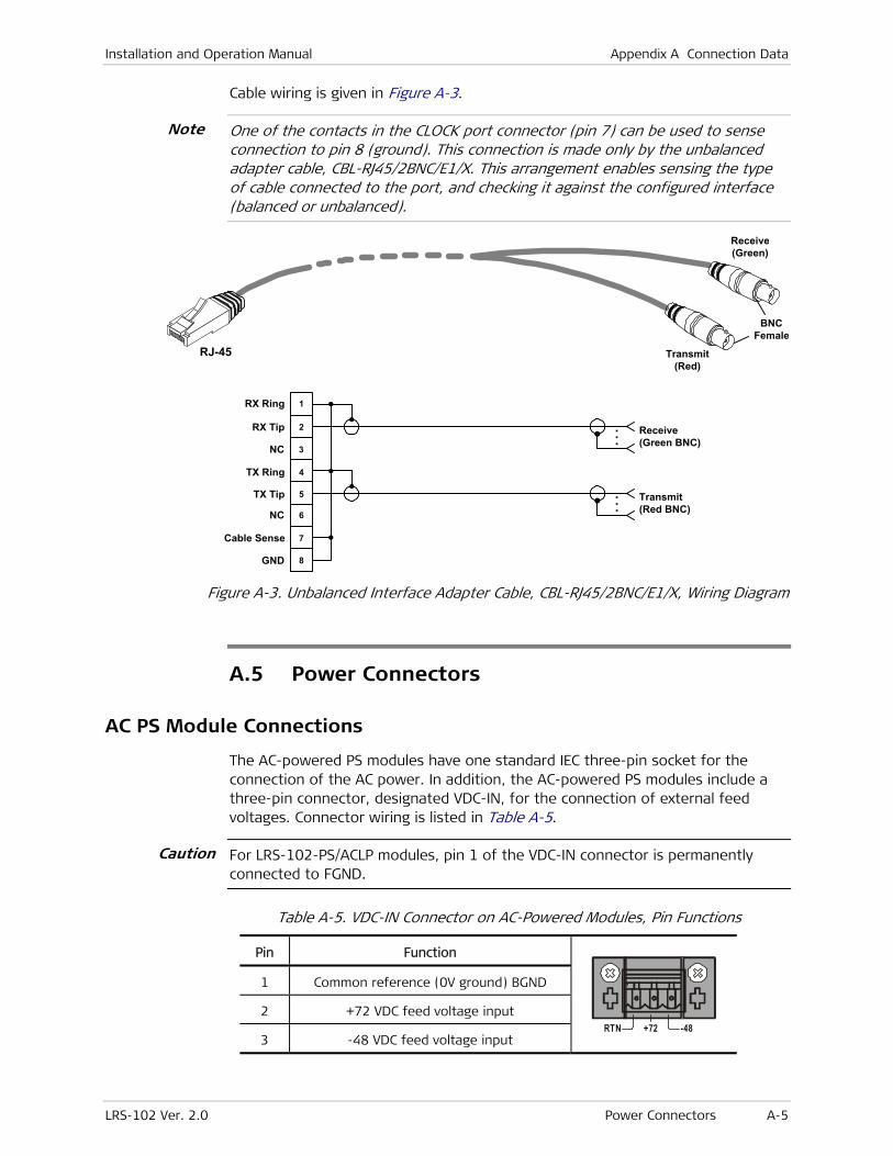
Installation and Operation Manual Appendix A Connection Data
LRS-102 Ver. 2.0 Power Connectors A-5
Cable wiring is given in Figure A-3.
One of the contacts in the CLOCK port connector (pin 7) can be used to sense connection to pin 8 (ground). This connection is made only by the unbalanced adapter cable, CBL-RJ45/2BNC/E1/X. This arrangement enables sensing the type of cable connected to the port, and checking it against the configured interface (balanced or unbalanced).
RJ-45
BNCFemale
Receive(Green)
Transmit(Red)
1
2
3
4
5
6
7
8
Transmit(Red BNC)
Receive(Green BNC)
RX Ring
RX Tip
NC
TX Ring
TX Tip
NC
Cable Sense
GND
...
...
Figure A-3. Unbalanced Interface Adapter Cable, CBL-RJ45/2BNC/E1/X, Wiring Diagram
A.5 Power Connectors
AC PS Module Connections
The AC-powered PS modules have one standard IEC three-pin socket for the connection of the AC power. In addition, the AC-powered PS modules include a three-pin connector, designated VDC-IN, for the connection of external feed voltages. Connector wiring is listed in Table A-5.
For LRS-102-PS/ACLP modules, pin 1 of the VDC-IN connector is permanently connected to FGND.
Table A-5. VDC-IN Connector on AC-Powered Modules, Pin Functions
Pin Function
RTN +72 -48
1 Common reference (0V ground) BGND
2 +72 VDC feed voltage input
3 -48 VDC feed voltage input
Note
Caution
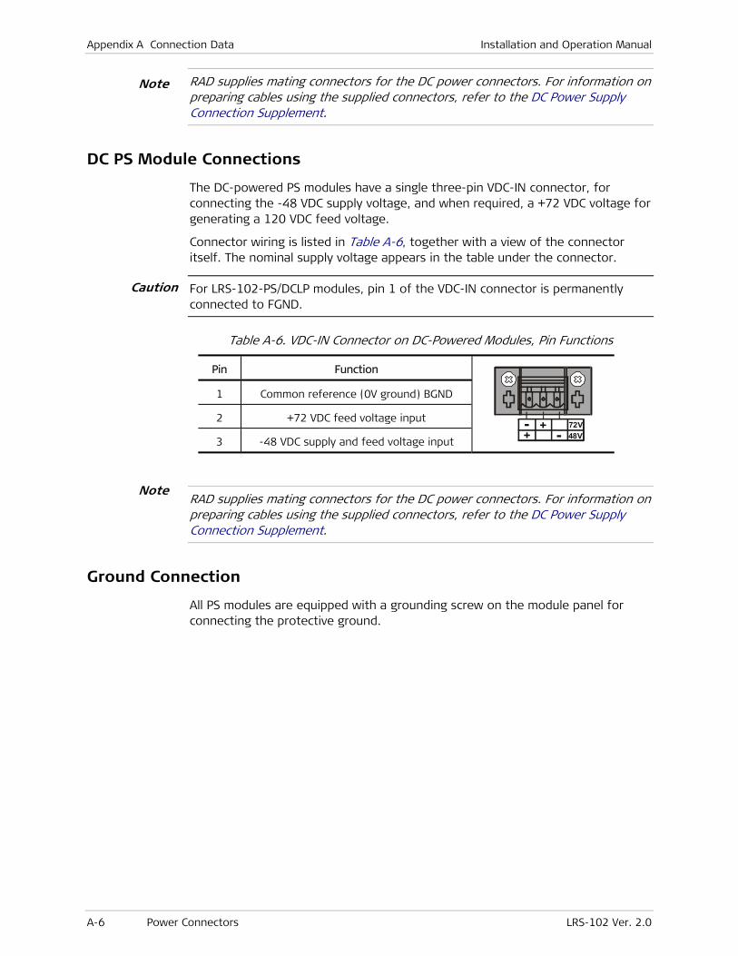
Appendix A Connection Data Installation and Operation Manual
A-6 Power Connectors LRS-102 Ver. 2.0
RAD supplies mating connectors for the DC power connectors. For information on preparing cables using the supplied connectors, refer to the DC Power Supply Connection Supplement.
DC PS Module Connections
The DC-powered PS modules have a single three-pin VDC-IN connector, for connecting the -48 VDC supply voltage, and when required, a +72 VDC voltage for generating a 120 VDC feed voltage.
Connector wiring is listed in Table A-6, together with a view of the connector itself. The nominal supply voltage appears in the table under the connector.
For LRS-102-PS/DCLP modules, pin 1 of the VDC-IN connector is permanently connected to FGND.
Table A-6. VDC-IN Connector on DC-Powered Modules, Pin Functions
Pin Function
72V48V
- + -
+
1 Common reference (0V ground) BGND
2 +72 VDC feed voltage input
3 -48 VDC supply and feed voltage input
RAD supplies mating connectors for the DC power connectors. For information on preparing cables using the supplied connectors, refer to the DC Power Supply Connection Supplement.
Ground Connection
All PS modules are equipped with a grounding screw on the module panel for connecting the protective ground.
Note
Note
Caution
LRS-102 Ver. 2.0 Overview B-1
Appendix B
Installing New Software Releases This Appendix presents procedures for downloading software to the LRS-102.
The procedures appearing in this Appendix can be used to:
1. Update the LRS-102 software when a new release becomes available.
2. Download again the software in case the stored software has been corrupted.
3. Download software to a new or repaired CL module.
4. Download software to I/O modules that support this capability.
B.1 Overview
LRS-102 operation is controlled by its management subsystem, located on the CL module, which cooperates with the local management subsystems of the other modules installed in the chassis. The software needed by the CL module is stored in flash memory, and therefore can be loaded by external means. This enables distributing software updates from remote locations, or from PCs used by technical support and maintenance personnel.
In addition to the CL module software, LRS-102 also enables downloading software to I/O modules.
Each of these subsystems can be independently updated, using separate software image files: these files have the extension .img, and their prefix depends on the target type.
The prefix is usually followed by a four-digit number that identifies a specific version (additional letters used for RAD internal purposes may follow the version number).
The CL module flash memory includes three software storage areas, one for each type of software image file:
• One area is automatically reserved for the CL module software.
The same software version must be stored in both CL modules: an alarm is generated if the CL modules hold different software versions.
• The other two areas (identified as File 1 and File 2 on the supervision terminal screens) can store two independent image files, in accordance with user’s requirements (for example, each area can hold a different version of

Appendix B Installing New Software Releases Installation and Operation Manual
B-2 Overview LRS-102 Ver. 2.0
link modules software). Moreover, the user can specify from which area to download software to each module.
The contents of these storage areas are not checked for consistency between the two CL modules.
The File Utilities menu provides the tools necessary to control downloading, and to manage the stored software files (refer to Chapter 4 for details).
Downloading Options for CL Modules Software
The CL module contains the most critical part of the system software, and therefore LRS-102 provides two options for downloading software to the CL modules:
• Using the File Utilities menu
• Using the boot menu.
Using the File Utilities Menu
The recommended software downloading method, explained in Section B.2, is downloading by means of the TFTP protocol, using SW & File Transfer CL option of the File Utilities menu.
Network administrators can use this procedure to distribute new software releases to all the managed LRS-102 units in the network from a central location.
When downloading by TFTP, the new software is always downloaded into the on-line CL module, and is stored in its flash memory.
After software decompression is completed, the on-line CL module is automatically reset. Resetting the on-line CL module has two effects:
• The new software is activated
• The other CL module (which currently stores the previous software version) is switched on-line.
Therefore, after receiving the messages that indicate flipping (switching) to the other CL module, repeat the downloading procedure: this time the new software will be downloaded into the other module. Following the resetting of the second CL module at the end of software downloading, the original CL module returns on-line.
Using the Boot Menu
Software downloading may also be performed using the boot menu, as explained in Section B.3. The boot menu can be reached while LRS-102 performs initialization, for example, after power-up.
You may need to start the loading from the boot menu whenever it is not possible to activate TFTP from the File Utilities menu (for example, because the LRS-102 software has not yet been downloaded or is corrupted).

Installation and Operation Manual Appendix B Installing New Software Releases
LRS-102 Ver. 2.0 Overview B-3
It is recommended that only authorized personnel use the boot menu procedures, because this menu provides many additional options that are intended for use only by technical support personnel.
The boot menu enables downloading two types of files:
• Boot manager files. The boot manager is a critical function that controls the power-up initialization and ensures that the application program is automatically run upon power-up. The boot manager also includes several utilities (some of them are used to download files, as explained in this Appendix). This type of file is seldom updated.
Downloading a boot manager file should be performed only by technical support personnel.
• Application files. These files carry the regular version updates. The following sections provide instructions for downloading application files.
Two software downloading options are available from the boot menu:
• Downloading using the Xmodem protocol. This is usually performed by downloading from a PC directly connected to the CONTROL DCE port of the CL module.
• Downloading using the TFTP protocol. This is usually performed by downloading from a host connected to the CONTROL ETH port of the active CL module, or from a remote location that provides an IP communication path to this LRS-102 port.
When downloading from the boot menu, you connect to only one CL module (the module to be loaded). Therefore, when updating the software to a new release, always repeat the process for the second module.
Downloading Options for Other Software
The other types of software are downloaded to the CL module using TFTP (using the File Utilities menu), and stored into the user-specified software storage area. As for the CL module software, downloading must be separately performed for each module (preferably starting with the on-line module).
After a software image is stored in the CL module, it can be downloaded to the desired modules using the SW & File Transfer I/O submenu of the File Utilities menu. As part of the downloading process, the CL module checks that the file being downloaded to a specific I/O module is a valid software image file for that target.
Note

Appendix B Installing New Software Releases Installation and Operation Manual
B-4 Software Updating Using File Utilities Menu LRS-102 Ver. 2.0
B.2 Software Updating Using File Utilities Menu
Unless otherwise specified, all the parameter values appearing in the following screens are given for illustration purposes only, and do not reflect recommended values.
Preparations for Using TFTP
The following conditions must be fulfilled before the TFTP protocol can be used for software downloading:
1. The required suite of protocols (which includes as a minimum the TCP/IP stack and the TFTP server and client software) must be installed on the other computer (the computer used to download files and/or accept uploaded files).
2. The LRS-102 must be assigned IP parameters for its management entity (that is, IP address, the associated subnet mask and a default gateway IP address for the online CL module) using the Configuration > Quick Setup or Configuration > System > Management > Host IP screen.
3. The management access options must be properly configured.
4. You must obtain the IP address of the other computer.
5. The TFTP protocol runs over IP, therefore it is necessary to ensure IP connectivity between the LRS-102 and the other computer. For example:
The Ethernet port of the other computer may be directly connected to one of the LRS-102 CONTROL ETH ports. In this case, their IP addresses must be in the same subnet.
The CONTROL ETH port and the other computer may be attached to the same LAN. In this case, their IP addresses must be in the same subnet.
The LRS-102 and the other computer may be attached to interconnected LANs.
IP connectivity can be checked using standard tools such as ping.
6. If you intend to initiate TFTP transfer using a supervision terminal connected to the LRS-102 CONTROL DCE connector, make sure that the LRS-102 supervisory port is properly configured. This is performed by means of the Configuration > System > Control Port > Serial Port screen.
Alternatively, you may use a Telnet host that can communicate with LRS-102 either through the CONTROL ETH ports, or through the one of the external links.
Note
Note

Installation and Operation Manual Appendix B Installing New Software Releases
LRS-102 Ver. 2.0 Software Updating Using File Utilities Menu B-5
Software Updating Procedure for CL Modules
Before Starting
1. Obtain the list of distribution files to be downloaded, and check that the required distribution files are stored on the TFTP server. Valid files have the extension .img, and the prefix depends on the image type.
2. Make sure that the TFTP server can communicate with the LRS-102, for example, ping the IP address assigned to the LRS-102 management entity (the host IP address).
Updating the CL Management Software
The following procedure is separately performed on each CL module, starting with the on-line module.
1. Open the File Utilities menu.
RS-102 File Utilities 1. S/W & File Transfer CL > 2. S/W & File Transfer I/O > > File system and File transfer operations ESC-prev.menu; !-main menu; &-exit; @-output 1 M/ 1 C -----------------------------------------------------------------------------
2. Select S/W & File Transfer CL on the File Utilities menu. You will see the S/W & File Transfer CL submenu.
RS-102 File Utilities>S/W & File Transfer CL 1. TFTP > > File Transfer operations %-Db Update; #-Db Undo; $-Sanity ESC-prev.menu; !-main menu; &-exit; @-output 1 M/ 1 C -----------------------------------------------------------------------------
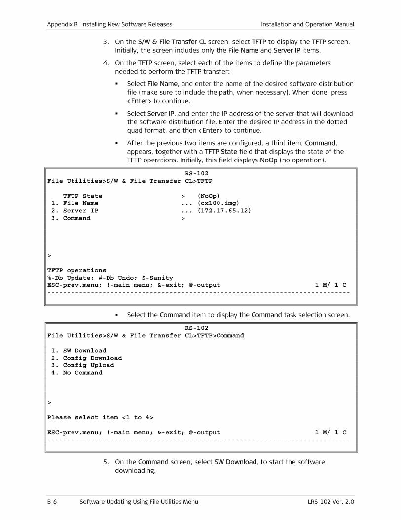
Appendix B Installing New Software Releases Installation and Operation Manual
B-6 Software Updating Using File Utilities Menu LRS-102 Ver. 2.0
3. On the S/W & File Transfer CL screen, select TFTP to display the TFTP screen. Initially, the screen includes only the File Name and Server IP items.
4. On the TFTP screen, select each of the items to define the parameters needed to perform the TFTP transfer:
Select File Name, and enter the name of the desired software distribution file (make sure to include the path, when necessary). When done, press <Enter> to continue.
Select Server IP, and enter the IP address of the server that will download the software distribution file. Enter the desired IP address in the dotted quad format, and then <Enter> to continue.
After the previous two items are configured, a third item, Command, appears, together with a TFTP State field that displays the state of the TFTP operations. Initially, this field displays NoOp (no operation).
RS-102 File Utilities>S/W & File Transfer CL>TFTP TFTP State > (NoOp) 1. File Name ... (cx100.img) 2. Server IP ... (172.17.65.12) 3. Command > > TFTP operations %-Db Update; #-Db Undo; $-Sanity ESC-prev.menu; !-main menu; &-exit; @-output 1 M/ 1 C -----------------------------------------------------------------------------
Select the Command item to display the Command task selection screen.
RS-102 File Utilities>S/W & File Transfer CL>TFTP>Command 1. SW Download 2. Config Download 3. Config Upload 4. No Command > Please select item <1 to 4> ESC-prev.menu; !-main menu; &-exit; @-output 1 M/ 1 C -----------------------------------------------------------------------------
5. On the Command screen, select SW Download, to start the software downloading.

Installation and Operation Manual Appendix B Installing New Software Releases
LRS-102 Ver. 2.0 Software Updating Using File Utilities Menu B-7
If no errors are detected, the downloading process starts, and its progress is displayed in the TFTP State field. Errors (for example, a protocol time-out) are reported in a separate TFTP Error field: if you see an error message, check and correct the error cause, and then select again the SW Download command.
6. After the transfer is successfully completed, the active CL module stores the file in its flash memory. Now the LRS-102 is automatically reset and the new software is decompressed. After the resetting is successfully completed, you will see the LRS-102 log in screen again.
If downloading failed, repeat the whole procedure.
7. Log in with the default parameters as follows:
In the User Name field, type the default user name, su, and then press <Enter>
In the Password field, type the default, 1234, and then press <Enter>.
8. You will see the main menu screen. The LRS-102 now uses the downloaded software.
9. Repeat the transfer to download the same file to the other CL module. For this purpose, first switch the other CL module on-line (use Config > System > Reset Device to send a reset command to the on-line module).
Software Updating Procedure for I/O Modules
To update the software of I/O modules that have this capability, first download the required software image to a selected software storage area of the CL module, and then download the stored software image to each I/O module.
A single CL module (the on-line module) can download software to any number of I/O modules. Therefore, it is not mandatory to download I/O modules software to both CL modules.
Moreover, the CL module can be configured to download the software to the desired modules in one step (the downloading itself is sequentially performed).
After the software is successfully downloaded to an I/O module, that module is automatically reset, and then starts using the new software version. This process momentarily disrupts the traffic flowing through the module that is being updated.
To download an I/O module image to a CL module:
1. Open the File Utilities menu.
2. Select the S/W & File Transfer I/O option on the File Utilities menu.
You will see the S/W & File Transfer I/O submenu.
Note
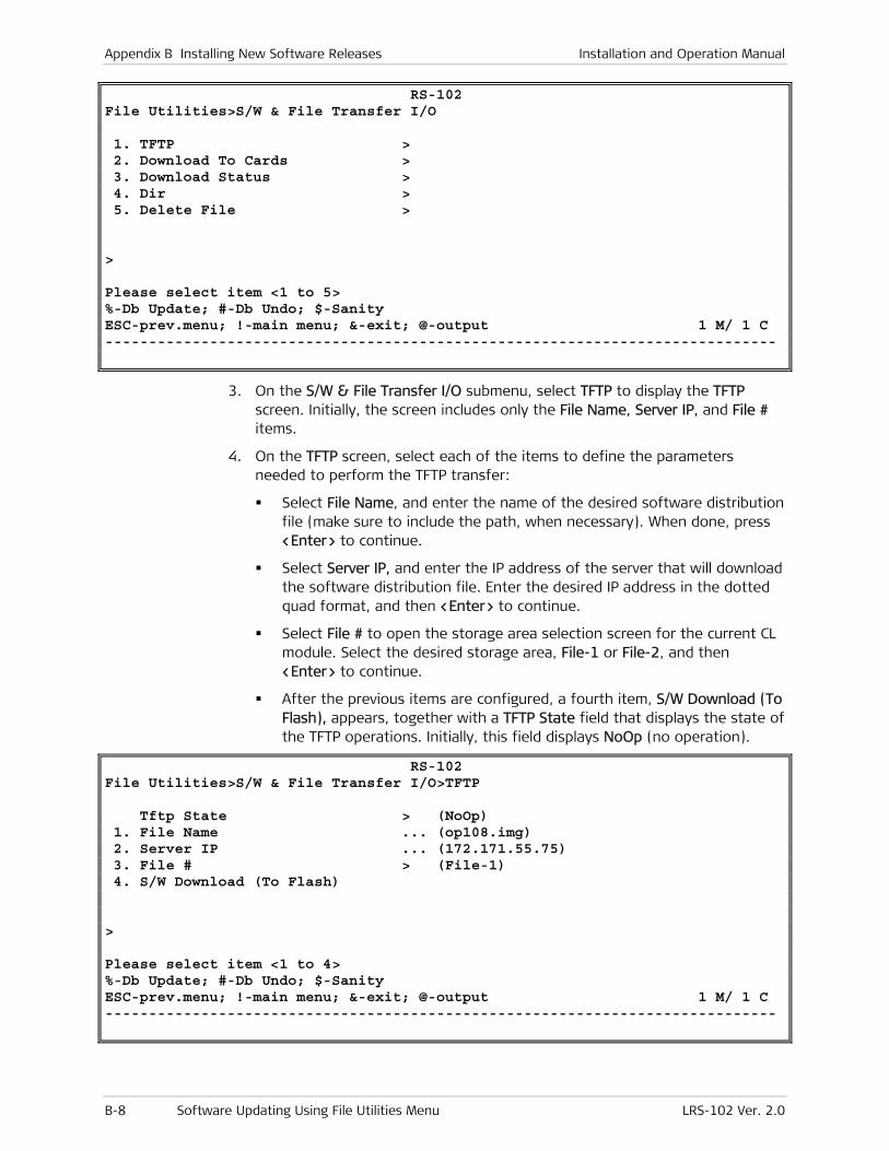
Appendix B Installing New Software Releases Installation and Operation Manual
B-8 Software Updating Using File Utilities Menu LRS-102 Ver. 2.0
RS-102 File Utilities>S/W & File Transfer I/O 1. TFTP > 2. Download To Cards > 3. Download Status > 4. Dir > 5. Delete File > > Please select item <1 to 5> %-Db Update; #-Db Undo; $-Sanity ESC-prev.menu; !-main menu; &-exit; @-output 1 M/ 1 C -----------------------------------------------------------------------------
3. On the S/W & File Transfer I/O submenu, select TFTP to display the TFTP screen. Initially, the screen includes only the File Name, Server IP, and File # items.
4. On the TFTP screen, select each of the items to define the parameters needed to perform the TFTP transfer:
Select File Name, and enter the name of the desired software distribution file (make sure to include the path, when necessary). When done, press <Enter> to continue.
Select Server IP, and enter the IP address of the server that will download the software distribution file. Enter the desired IP address in the dotted quad format, and then <Enter> to continue.
Select File # to open the storage area selection screen for the current CL module. Select the desired storage area, File-1 or File-2, and then <Enter> to continue.
After the previous items are configured, a fourth item, S/W Download (To Flash), appears, together with a TFTP State field that displays the state of the TFTP operations. Initially, this field displays NoOp (no operation).
RS-102 File Utilities>S/W & File Transfer I/O>TFTP Tftp State > (NoOp) 1. File Name ... (op108.img) 2. Server IP ... (172.171.55.75) 3. File # > (File-1) 4. S/W Download (To Flash) > Please select item <1 to 4> %-Db Update; #-Db Undo; $-Sanity ESC-prev.menu; !-main menu; &-exit; @-output 1 M/ 1 C -----------------------------------------------------------------------------
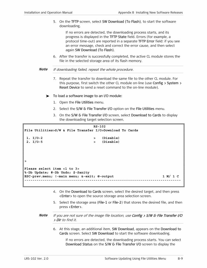
Installation and Operation Manual Appendix B Installing New Software Releases
LRS-102 Ver. 2.0 Software Updating Using File Utilities Menu B-9
5. On the TFTP screen, select SW Download (To Flash), to start the software downloading.
If no errors are detected, the downloading process starts, and its progress is displayed in the TFTP State field. Errors (for example, a protocol time-out) are reported in a separate TFTP Error field: if you see an error message, check and correct the error cause, and then select again SW Download (To Flash).
6. After the transfer is successfully completed, the active CL module stores the file in the selected storage area of its flash memory.
If downloading failed, repeat the whole procedure.
7. Repeat the transfer to download the same file to the other CL module. For this purpose, first switch the other CL module on-line (use Config > System > Reset Device to send a reset command to the on-line module).
To load a software image to an I/O module:
1. Open the File Utilities menu.
2. Select the S/W & File Transfer I/O option on the File Utilities menu.
3. On the S/W & File Transfer I/O screen, select Download to Cards to display the downloading target selection screen.
RS-102 File Utilities>S/W & File Transfer I/O>Download To Cards 1. I/O-2 > (Disable) 2. I/O-5 > (Disable) > Please select item <1 to 3> %-Db Update; #-Db Undo; $-Sanity ESC-prev.menu; !-main menu; &-exit; @-output 1 M/ 1 C -----------------------------------------------------------------------------
4. On the Download to Cards screen, select the desired target, and then press <Enter> to open the source storage area selection screen.
5. Select the storage area (File-1 or File-2) that stores the desired file, and then press <Enter>.
If you are not sure of the image file location, use Config > S/W & File Transfer I/O > Dir to find it.
6. At this stage, an additional item, SW Download, appears on the Download to Cards screen. Select SW Download to start the software downloading.
If no errors are detected, the downloading process starts. You can select Download Status on the S/W & File Transfer I/O screen to display the
Note
Note

Appendix B Installing New Software Releases Installation and Operation Manual
B-10 Software Downloading From the Boot Menu LRS-102 Ver. 2.0
progress. If you see an error message, check and correct the error cause, and then select again the SW Download command.
7. After the transfer is successfully completed, the I/O module is automatically reset and the new software is decompressed. After the resetting is successfully completed, the I/O module is again ready to carry traffic.
If downloading failed, repeat the whole procedure.
B.3 Software Downloading From the Boot Menu
Software Downloading Procedure Using Xmodem Protocol
Before starting, copy the prescribed software file to the PC disk.
Preparations for Using Xmodem Protocol
1. Connect the serial RS-232 communication port of a PC running a terminal emulation program (for example, the HyperTerminal utility available with most Microsoft Inc. Windows™ releases) to the LRS-102 CONTROL DCE connector. Select the emulated terminal type as VT-100.
2. Configure the communication parameters of the selected serial port for asynchronous communication for 115.2 kbps, no parity, one start bit, eight data bits and one stop bit. Turn flow control off.
3. If the LRS-102 operates, disconnect its power.
Procedure
1. Start the terminal emulation program in accordance with the configuration parameters described above.
2. When ready, turn the LRS-102 on, and immediately start pressing the <Enter> key many times in sequence until you see the boot manager screen. A typical screen is shown below (the exact version and date displayed by your LRS-102 may be different).
If you miss the timing, the LRS-102 will perform a regular reboot process (this process starts with Loading and ends with a Running message).
Note
Note

Installation and Operation Manual Appendix B Installing New Software Releases
LRS-102 Ver. 2.0 Software Downloading From the Boot Menu B-11
MPCLX boot version 2.00 (Jun 5 2005) Boot manager version 10.00 (Jun 5 2005) 0 - Exit boot-manager 1 - Dir 2 - Set active software copy 3 - Delete software copy 4 - Download boot manager or an application by XMODEM 5 - Format Flash 6 - Show basic hardware information 7 - Reset board 8 - System configuration 9 - Download boot manager or an application by TFTP Press the ESC key to return to the main menu Select:
3. Select Download boot manager or an application by XMODEM. You are now prompted to select the type of file to be downloaded.
Choose the software you want to work on 0 - boot-manager 1 - application file Select: 1
4. Type 1 to download a LRS-102 software update.
5. You will see a message that requests the partition number to which the new software is to be downloaded, and offers a recommended value. If there is no special reason to select a different value, type the recommended number and then press <Enter>. A typical display is shown below:
Select Copy number for download ( 1 ) Select: 1
6. The process starts, and you will see:
Delete Partition please wait ....
Please start the XMODEM download.
7. Start the transfer in accordance with the program you are using. For example, if you are using the Windows HyperTerminal utility:
Select Transfer in the HyperTerminal menu bar, and then select Send File on the Transfer menu.
You will see the Send File window:
Select the prescribed LRS-102 software file name (you may use the Browse function to find it).
In the Protocol field, select Xmodem.
When ready, press Send in the Send File window. You can now monitor the progress of the downloading in the Send File window. The ON LINE indicator of the CL module flashes in green during the downloading.
If downloading fails, repeat the whole procedure.
Note
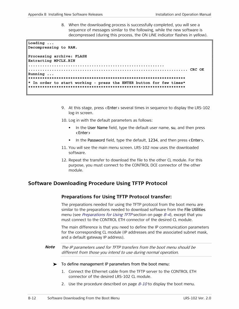
Appendix B Installing New Software Releases Installation and Operation Manual
B-12 Software Downloading From the Boot Menu LRS-102 Ver. 2.0
8. When the downloading process is successfully completed, you will see a sequence of messages similar to the following, while the new software is decompressed (during this process, the ON LINE indicator flashes in yellow).
Loading ... Decompressing to RAM. Processing archive: FLASH Extracting MPCLX.BIN .......................................................... .................................................................... CRC OK Running ... ******************************************************************* * In order to start working - press the ENTER button for few times* *******************************************************************
9. At this stage, press <Enter> several times in sequence to display the LRS-102 log-in screen.
10. Log in with the default parameters as follows:
In the User Name field, type the default user name, su, and then press <Enter>
In the Password field, type the default, 1234, and then press <Enter>.
11. You will see the main menu screen. LRS-102 now uses the downloaded software.
12. Repeat the transfer to download the file to the other CL module. For this purpose, you must connect to the CONTROL DCE connector of the other module.
Software Downloading Procedure Using TFTP Protocol
Preparations for Using TFTP Protocol transfer:
The preparations needed for using the TFTP protocol from the boot menu are similar to the preparations needed to download software from the File Utilities menu (see Preparations for Using TFTP section on page B-4), except that you must connect to the CONTROL ETH connector of the desired CL module.
The main difference is that you need to define the IP communication parameters for the corresponding CL module (IP addresses and the associated subnet mask, and a default gateway IP address).
The IP parameters used for TFTP transfers from the boot menu should be different from those you intend to use during normal operation.
To define management IP parameters from the boot menu:
1. Connect the Ethernet cable from the TFTP server to the CONTROL ETH connector of the desired LRS-102 CL module.
2. Use the procedure described on page B-10 to display the boot menu.
Note
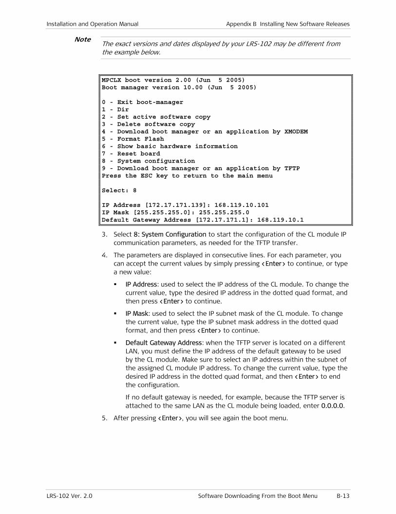
Installation and Operation Manual Appendix B Installing New Software Releases
LRS-102 Ver. 2.0 Software Downloading From the Boot Menu B-13
The exact versions and dates displayed by your LRS-102 may be different from the example below.
MPCLX boot version 2.00 (Jun 5 2005) Boot manager version 10.00 (Jun 5 2005) 0 - Exit boot-manager 1 - Dir 2 - Set active software copy 3 - Delete software copy 4 - Download boot manager or an application by XMODEM 5 - Format Flash 6 - Show basic hardware information 7 - Reset board 8 - System configuration 9 - Download boot manager or an application by TFTP Press the ESC key to return to the main menu Select: 8 IP Address [172.17.171.139]: 168.119.10.101 IP Mask [255.255.255.0]: 255.255.255.0 Default Gateway Address [172.17.171.1]: 168.119.10.1
3. Select 8: System Configuration to start the configuration of the CL module IP communication parameters, as needed for the TFTP transfer.
4. The parameters are displayed in consecutive lines. For each parameter, you can accept the current values by simply pressing <Enter> to continue, or type a new value:
IP Address: used to select the IP address of the CL module. To change the current value, type the desired IP address in the dotted quad format, and then press <Enter> to continue.
IP Mask: used to select the IP subnet mask of the CL module. To change the current value, type the IP subnet mask address in the dotted quad format, and then press <Enter> to continue.
Default Gateway Address: when the TFTP server is located on a different LAN, you must define the IP address of the default gateway to be used by the CL module. Make sure to select an IP address within the subnet of the assigned CL module IP address. To change the current value, type the desired IP address in the dotted quad format, and then <Enter> to end the configuration.
If no default gateway is needed, for example, because the TFTP server is attached to the same LAN as the CL module being loaded, enter 0.0.0.0.
5. After pressing <Enter>, you will see again the boot menu.
Note
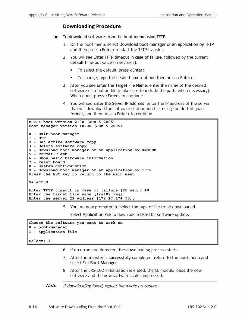
Appendix B Installing New Software Releases Installation and Operation Manual
B-14 Software Downloading From the Boot Menu LRS-102 Ver. 2.0
Downloading Procedure
To download software from the boot menu using TFTP:
1. On the boot menu, select Download boot manager or an application by TFTP and then press <Enter> to start the TFTP transfer.
2. You will see Enter TFTP timeout in case of failure, followed by the current default time-out value (in seconds):
To select the default, press <Enter>
To change, type the desired time-out and then press <Enter>.
3. After you see Enter the Target File Name, enter the name of the desired software distribution file (make sure to include the path, when necessary). When done, press <Enter> to continue.
4. You will see Enter the Server IP address: enter the IP address of the server that will download the software distribution file, using the dotted quad format, and then press <Enter> to continue.
MPCLX boot version 2.00 (Jun 5 2005) Boot manager version 10.00 (Jun 5 2005) 0 - Exit boot-manager 1 - Dir 2 - Set active software copy 3 - Delete software copy 4 - Download boot manager or an application by XMODEM 5 - Format Flash 6 - Show basic hardware information 7 - Reset board 8 - System configuration 9 - Download boot manager or an application by TFTP Press the ESC key to return to the main menu Select:9 Enter TFTP timeout in case of failure [20 sec]: 40 Enter the target file name [lrs102.img]: Enter the server IP address [172.17.174.50]:
5. You are now prompted to select the type of file to be downloaded.
Select Application File to download a LRS-102 software update.
Choose the software you want to work on 0 - boot-manager 1 - application file Select: 1
6. If no errors are detected, the downloading process starts.
7. After the transfer is successfully completed, return to the boot menu and select Exit Boot-Manager.
8. After the LRS-102 initialization is ended, the CL module loads the new software and the new software is decompressed.
If downloading failed, repeat the whole procedure.
Note
Installation and Operation Manual Appendix B Installing New Software Releases
LRS-102 Ver. 2.0 Software Downloading From the Boot Menu B-15
9. At this stage, press <Enter> several times in sequence to display the LRS-102 log-in screen.
10. Log in with the default parameters as follows:
In the User Name field, type the default user name, su, and then press <Enter>
In the Password field, type the default, 1234, and then press <Enter>.
11. You will see the main menu screen.
12. If necessary, repeat the process for the second CL module.

Appendix B Installing New Software Releases Installation and Operation Manual
B-16 Software Downloading From the Boot Menu LRS-102 Ver. 2.0
LRS-102 Ver. 2.0 I-1
Index
—A—
AC power connector, A-5 Administrative features, 4-35 Alarm Attributes
Alarm Description, 6-14 Alarm ID, 6-14 Filter/Threshold, 6-14 Invert, 6-14 Mask, 6-14 Port Num, 6-14 Port Type, 6-14 Reset Val, 6-14 Set Val, 6-14 Slot, 6-14
ALARM connector, 2-15, A-3 Alarms, 6-11
alarm attributes, 6-12 alarm buffer, 6-11 alarm priority, 6-20 alarm relays, 6-11 alarm reporting, 6-18
Alarm, 6-19 Log, 6-19 Major LED, 6-19 Minor LED, 6-19 Relay-1, 6-19 Relay-2, 6-19 Report, 6-19
alarm threshold window, 6-22 configuring alarm handling, 6-11 displaying, 6-23 interpreting, 6-28 list, 6-28 monitoring, 6-23, 6-24
Alarms Configuration Alarm Attributes, 6-12 Alarm Priority, 6-12 Alarm Report, 6-12 Alarm Window, 6-12 Init Alarm Priority, 6-12 Init Alarm Report, 6-12
ALM indicator, 2-15 ASMi-54C, 1-9
—B—
Blank panels, 2-17 BNC patch panel, 2-21 Boot menu
TFTP transfer default gateway address, B-13 downloading procedure, B-14 IP address, B-13 IP mask, B-13 preparations, B-12
X-modem transfer preparations, B-10
procedure, B-10 Protocol, B-11 Send File, B-11 Transfer, B-11
Brackets, 2-17, 2-18 Bridge ports
mapping to management flow, 4-67 add new bridge port to flow, 4-67
mapping to traffic flows, 4-61 add new bridge port to flow, 4-62 Port, 4-63 Slot, 4-62
—C—
CBL-RJ45/2BNC/E1/X, 2-3, 2-20, A-4 CL modules, 1-7
ALARM connector, 2-15 ALM indicator, 2-15 CL panel, 2-13 CLOCK connector (CLS.1 only)
LOS indicator, 2-15 ON indicator, 2-15
connections management, 2-19 supervision terminal, 2-19
CONTROL DCE connector, 2-15
CONTROL ETH ACT indicator, 2-15 connector, 2-15 LINK indicator, 2-15
functions, 1-10 installation, 2-15 models, 1-1 module installation, 2-13 normal indications, 3-3 ON LINE indicator, 2-14 redundancy, 1-13 removing, 2-16 replacing during operation
chassis with 1 CL module, 2-16 chassis with 2 CL modules, 2-16
CLOCK connector (CLS.1 only) connections
management, 2-19 supervision terminal, 2-19
connector data, A-4 LOS indicator, 2-15 ON indicator, 2-15
CLS.1 module, 1-7 ConfiguRAD, 1-12, 3-9, 3-32, 3-33 Configuration errors, 6-8 Configuration menu, 3-24 Configuration procedure
Alarms, 6-11 alarm attributes, 6-12 alarm priority, 6-20

Index Installation and Operation Manual
I-2 LRS-102 Ver. 2.0
alarm reporting, 6-18 alarm threshold window, 6-22
control port parameters, 4-16 date & time parameters, 4-31 device info, 4-31 ETH port parameters, 4-23 Ethernet flows, 4-59
management flow, 4-65 traffic flow, 4-60
host IP parameters, 4-25 management access parameters, 4-27 manager list, 4-28
Alarms Trap, 4-30 IP Address, 4-30 Managers ID, 4-29
physical layer parameters, 4-52 serial port parameters, 4-17 SNMPv3 management, 4-33
configuration sequence, 4-38 enabling/disabling, 4-37 Notify, 4-45 SNMP Engine ID, 4-35 SNMPv1/v3 Mapping, 4-49 SNMPv3 setting, 4-38 Target Params, 4-44 Targets & Notify, 4-43 Users, 4-40
system parameters, 4-9 Configuration>Applications, 3-29, 4-59 Configuration>DB Tools, 3-29, 4-3 Configuration>Physical Layer, 3-28, 4-52 Configuration>System, 3-25, 4-10 Connections
alarm port, 2-4 CL modules, 2-3 E1 port, 2-2 feed voltages, 2-19 ground, A-6 optical ports, 2-2 power, 2-19 station clock (CLS.1 only), 2-3 T1 port, 2-2
CONTROL DCE, 2-15 connection data, A-1
CONTROL ETH, 2-15 ACT indicator, 2-15 connection data, A-3 LINK indicator, 2-15
—D—
DB Tools, 3-29, 4-3 DC power connector, A-6 Default DB, 4-4 Delete DB, 4-4 Deleting files, 4-79 Device Info
Contact Person, 4-31 Device Name, 4-31 Location ID, 4-31 Object ID, 4-31 Sys Description, 4-31
Diagnostics, 1-14, 6-42 active tests, 6-45 menu, 3-30, 6-42
physical layer, 6-43 ping test, 6-44
Dir function, 4-78 Download to Cards, B-9 Downloading
Boot menu, B-2, B-10 X-modem transfer, B-10
File Utilities, B-2, B-4 downloading to CL modules, B-2 downloading to I/O modules, B-3
software image types, B-1
—E—
ESD, 2-6 ETH port
Admin Status, 4-24 Name, 4-24
Ethernet flows configuration, 4-59
management flow, 4-65 traffic flow, 4-60
—F—
Factory defaults, 3-4 Feed voltage connections, 2-19 Feed voltage sources, 1-16 File Utilities, 4-70
Download/upload by TFTP Config Download, 4-72 Config Upload, 4-73 SW Download, 4-72
File system Delete File, 4-79 Dir function, 4-78
TFTP Command, B-6 download configuration files, 4-74 downloading to CL modules, B-5 downloading to I/O modules, B-7 File #, 4-76, B-8 File Name, 4-72, 4-76, B-6, B-8 preparations for transfer, B-4 Server IP, 4-72, 4-76, B-6, B-8 to I/O modules, 4-74 update CL software, 4-72, B-5 upload configuration files, 4-74
Flows, 4-59 Ethernet management flow configuration, 4-65
add new management flow, 4-66 BP, 4-68 BP Name, 4-69 Host NMS Source, 4-69 mapping bridge ports, 4-67 Name, 4-66 Port, 4-69 Rate, 4-69 Slot, 4-69 VLAN ID, 4-66 VLAN Priority Tag, 4-66
Ethernet traffic flow configuration add new traffic flow, 4-61 BP, 4-63 BP Name, 4-64 C-VLAN ID, 4-63
Installation and Operation Manual Index
LRS-102 Ver. 2.0 I-3
C-VLAN Type, 4-63 E-LINE, 4-61 mapping bridge ports, 4-61 Name, 4-61 Port, 4-64 Rate, 4-64 Slot, 4-64 SP-VLAN, 4-63
Frequently Asked Questions, 6-39 Front panel, 2-9
—G—
Grounding, 2-6, 2-18
—H—
Hardware Problems troubleshooting, 6-38
Host IP Default Gateway, 4-26 Host IP Address, 4-26 Read community, 4-27 Subnet Mask, 4-26 Traps community, 4-27 Write community, 4-27
—I—
I/O modules, 1-8 ASMi-54C, 1-9 connections, 2-21 installation, 2-17 OP-106C, 1-9 OP-108C, 1-9
Indications normal, 3-3
CLOCK interface status, 3-3 CONTROL ETH interface, 3-3 system, 3-3
Indicators, 2-9 Installation
blank panels, 2-17 bracket attachment, 2-17, 2-18 cable connections, 2-18 CL modules, 2-13, 2-15
connections, 2-19 module panel, 2-13
CLOCK connector (CLS.1 only) connections, 2-19
connecting to BNC patch panel, 2-21 connecting to I/O modules, 2-21 feed voltage connections, 2-19 front panel, 2-9 grounding, 2-18 I/O modules, 2-17 LRS-102 enclosure, 2-17
brackets for 19 in. racks, 2-17 brackets for 23 in. racks, 2-18
power connections, 2-19 PS modules, 2-10
internal setting, 2-12 panels, 2-10
rear panel, 2-8 requirements
AC power, 2-1
ambient, 2-4 DC power, 2-1, A-5, A-6 electromagnetic compatibility, 2-4 front and rear panel clearance, 2-4 site requirements, 2-1
Inventory menu, 3-23, 4-80 SW/HW Rev, 4-81
Hardware Revision, 4-82 Installed Card, 4-82 Programmed Card, 4-82 Slot, 4-82 Software Version, 4-82
System, 4-80 Hardware Revision, 4-81 Software Version, 4-81 System Description, 4-81
—L—
Load DB, 4-4 Load HW, 4-4 Log-in, 3-9 Logistic (inventory) information, 4-80 LRS-102
applications, 1-2 ASMi-54C, 1-3 OP-108C, OP-106C, 1-2
brackets for 19 in. racks, 2-17 brackets for 23 in. racks, 2-18 CL module, 1-7 CLS.1 module, 1-7 enclosure description, 1-5, 2-17 features, 1-3 feed voltage sources, 1-16 functional description, 1-10 management functions, 1-10 mounting the unit, 2-5 overview, 1-1 physical description, 1-5 power supply subsystem, 1-15 product options, 1-1 PS modules, 1-7 technical specifications, 1-17
—M—
Main menu, 3-22 Management subsystem, 1-10
access options, 1-11 alarm collection, 1-13 alarm reporting, 1-13 Ethernet port, 1-12 serial port, 1-12 SNMP, 1-11 statistics support, 1-13
Menu structure Configuration menu, 3-24 Configuration>Applications, 3-29, 4-59 Configuration>DB Tools, 3-29, 4-3 Configuration>Physical Layer, 3-28, 4-52 Configuration>System, 3-25, 4-10 Diagnostics menu, 3-30, 6-42 File Utilities menu, 4-70 Inventory menu, 3-23 Main menu, 3-22 Monitoring menu, 3-30, 6-2
Index Installation and Operation Manual
I-4 LRS-102 Ver. 2.0
Monitoring menu, 3-30, 6-2 active alarms, 6-23, 6-24 Alarms, 6-23 CL physical layer
station clock (CLS.1 only), 6-4 CL Status
Active DB, 6-3 Alarm Severity, 6-3 CL Temperature, 6-4 Configuration File Usage, 6-3 DB Checksum, 6-3 Last DB Update, 6-4 System Control Activity, 6-3 Test Status, 6-3
physical layer, 6-6 system
CL status, 6-3 remote agents, 6-5
Monitoring power-up sequence, 3-1
—O—
ON LINE indicator, 2-14 OP-106C, 1-9 OP-108C, 1-9 overview, 4-33
—P—
Package contents, 2-5 required equipment, 2-5
Physical layer configuration, 4-52 diagnostics, 6-43 monitoring, 6-6
Ping test, 6-44 Power
AC, 2-1 DC, 2-1, A-5, A-6
floating source, 2-2 positive source terminal grounded, 2-2
Power connections, 2-19 POWER SUPPLY indicator, 2-9 Power supply subsystem, 1-15 Preliminary configuration, 3-12
supervision terminal, 3-10 PS modules, 1-7
installation, 2-10 internal settings, 2-12 panels, 2-10 removing, 2-13
—R—
Rear panel, 2-8 Redundancy, 1-13 Remote agents, 6-5
Interface, 6-6 IP Address, 6-6 Logical Distance, 6-6 Mux Name, 6-6 Physical Distance, 6-6
Reset, 6-29
—S—
S/W & File Transfer CL, 4-72, 4-75, B-6
S/W & File Transfer I/O, 4-76, 4-78, B-8, B-9 Safety
ESD, 2-6 grounding, 2-6 laser, 2-20 module handling, 2-7
Sanity errors errors, 6-8 list, 6-8 warnings, 6-8
Security level, 4-34 Serial Port
Baud Rate, 4-18 Security Timeout, 4-18
Site requirements, 2-1 AC power, 2-1 ambient, 2-4 connections
alarm port, 2-4 E1, 2-2 Ethernet management port, 2-3 optical cables, 2-3 optical ports, 2-2 serial port, 2-4 station clock (CLS.1 only), 2-3 T1, 2-2
DC power, 2-1 electromagnetic compatibility, 2-4 front and rear panel clearance, 2-4
SNMP Engine ID, 4-35 IPv4, 4-36 MAC Address, 4-36 Text, 4-36
SNMP management, 3-33 MIBs, 3-33 preparing for, 3-34
SNMP support, 1-11 SNMPv3, 1-11, 4-33
administrative features, 4-35 enabling/disabling, 4-37 security level, 4-34 VACM, 4-35
SNMPv3 Setting, 4-38 Engine Boots, 4-39 Engine Time, 4-39 Notify, 4-45 SNMP Factory Defaults, 4-40 SNMP Message Size, 4-39 SNMPv1/v3 Mapping, 4-49
Community Index, 4-49 Community Name, 4-49 Security Name, 4-49 Transport Tag, 4-50
Summary Target Table, 4-50 Summary User Table, 4-50 Target Params, 4-44
Message Processing Model, 4-45 Name, 4-45 Security Level, 4-45 Security Model, 4-45 Security Name, 4-45
Targets & Notify, 4-43 Notify, 4-45, 4-46 Notify - Name, 4-46 Notify - Tag, 4-46

Installation and Operation Manual Index
LRS-102 Ver. 2.0 I-5
Notify - Type, 4-46 Target Address, 4-48 Target Address – IP Address, 4-48 Target Address - Name, 4-48 Target Address – Params Name, 4-48 Target Address – Tag List, 4-48 Target Params, 4-44 Trap, 4-47 Trap - Notify Name, 4-47 Trap - Trap Name, 4-47
Users, 4-40 Authentication Password, 4-42 Authentication Protocol, 4-42 Privacy Password, 4-43 Privacy Protocol, 4-42 Security Name, 4-42
SSM values, 6-5
Station Clock Admin Status, 4-56 Cable Type, 6-4 Clock Rate, 4-56 Interface Type, 4-56 Line Code, 4-56 Rx Gain Limit, 4-57 Rx Source, 4-57 Rx SSM, 6-5 SSM, 4-57 Status, 6-4 Transmit Timing Source, 4-56
Statistics, 1-13 Supervision terminal, 3-15, 3-21
ending terminal session, 3-21 general procedures, 3-19 menu structure
Configuration menu, 3-24 Configuration>Applications, 3-29, 4-59 Configuration>DB Tools, 3-29, 4-3 Configuration>Physical Layer, 3-28, 4-52 Configuration>System, 3-25, 4-10 Diagnostics menu, 3-30, 6-42 File Utilities menu, 4-70 Inventory menu, 3-23 Main menu, 3-22 Monitoring menu, 3-30, 6-2
power-up process, 3-17 saving changes, 3-21 terminal screen description, 3-17
bottom line, 3-19 header, 3-18 save, 3-19 status indicator, 3-18 work area, 3-18
SYSTEM ALARM indicator, 2-9 System configuration
Alarms, 6-11 alarm attributes, 6-12 alarm priority, 6-20 alarm reporting, 6-18 alarm threshold window, 6-22
Card Type, 3-13, 4-14 configuration and management options, 3-9 Control Port, 3-13, 4-16 Date & Time, 3-15, 4-31 Default DB, 3-13
device info, 4-31 ETH port, 4-23 Factory Default, 3-13, 4-13 Host IP, 3-14
parameters, 4-25 Load HW, 3-13 log-in, 3-9 Management, 3-14 management access, 4-27 Manager List, 3-14, 4-28 managing databases, 4-2 Mng Access, 3-14 preliminary configuration
sequence, 3-12 reloading factory defaults, 4-12 reset device, 4-13 serial port parameters, 4-17 Set Date Format, 3-15 Speed, 3-14 supervision terminal, 3-15 Telnet, 3-31 Telnet Access, 3-14 Update DB, 3-13, 3-15 Web Access, 3-14 working with supervision terminal, 3-10
SYSTEM TEST indicator, 2-9
—T—
Targets & Notify, 4-43 Technical specifications, 1-17 Technical support, 6-41 Telnet, 3-31 Testing, 6-42 TFTP, 4-72, 4-75, B-6, B-8
Client file name, 4-72, 4-76, B-6, B-8 Command, B-6 Config Download, 4-72 Config Upload, 4-73 downloading/uploading files, 4-72 File #, 4-76, B-8 Server IP, 4-72, 4-76, B-6, B-8 SW Download, 4-72
Timing, 1-14 internal timing, 1-14 station clock interface (CLS.1 only), 1-15 station timing (CLS.1 only), 1-14
Traps, 6-11, 6-35 list, 6-35 OID, 6-35
Troubleshooting hardware problems, 6-38 preliminary checks, 6-37
Turn off, 3-35 Turn on, 3-1
—U—
Update DB, 4-4 Users, 4-40 USM, 4-34
—V—
VACM, 4-35
Index Installation and Operation Manual
I-6 LRS-102 Ver. 2.0
—W—
Working with SNMP management stations SNMP management, 3-33
preparing for, 3-34 Working with supervision terminal, 3-10
Working with Telnet, 3-31 Working with Web Browsers, 3-32
general procedures, 3-32 guidelines, 3-32 preparations, 3-32

24 Raoul Wallenberg Street, Tel Aviv 69719, Israel
Tel: +972-3-6458181, Fax +972-3-6483331, +972-3-6498250
E-mail: [email protected], Web site: http://www.rad.com
Customer Response Form
RAD Data Communications would like your help in improving its product documentation. Please complete and return this form by mail or by fax or send us an e-mail with your comments.
Thank you for your assistance!
Manual Name: LRS-102 Ver. 2.0
Publication Number: 416-200-12/08
Please grade the manual according to the following factors:
Excellent Good Fair Poor Very Poor
Installation instructions � � � � �
Operating instructions � � � � �
Manual organization � � � � �
Illustrations � � � � �
The manual as a whole � � � � �
What did you like about the manual?


Error Report
Type of error(s) or problem(s):
� Incompatibility with product
� Difficulty in understanding text
� Regulatory information (Safety, Compliance, Warnings, etc.)
� Difficulty in finding needed information
� Missing information
� Illogical flow of information
� Style (spelling, grammar, references, etc.)
� Appearance
� Other
Please list the exact page numbers with the error(s), detail the errors you found (information missing, unclear or inadequately explained, etc.) and attach the page to your fax, if necessary.
Please add any comments or suggestions you may have.
You are: � Distributor
� End user
� VAR
� Other
Who is your distributor?
Your name and company:
Job title:
Address:
Direct telephone number and extension:
Fax number:
E-mail:


Publication No. 416-200-12/08
Order this publication by Catalog No. 803831
International Headquarters 24 Raoul Wallenberg Street
Tel Aviv 69719, Israel
Tel. 972-3-6458181
Fax 972-3-6498250, 6474436
E-mail [email protected]
North America Headquarters 900 Corporate Drive
Mahwah, NJ 07430, USA
Tel. 201-5291100 Toll free 1-800-4447234
Fax 201-5295777
E-mail [email protected]
www.rad.com The Access Company