Embed Size (px)
DESCRIPTION
This manual explains how different systems from CAT994F works individually. It is a great manual for those who need information about LOADERS CAT 994F
Citation preview

SERVXXXXMarch 2005
TECHNICAL PRESENTATION
994F WHEEL LOADERINTRODUCTION
Service Training Meeting Guide(STMG)
SERVICE TRAINING

994F WHEEL LOADER - INTRODUCTIONMEETING GUIDE XXXX SLIDES ANDSCRIPT
AUDIENCEService personnel who understand the principles of machine systems operation, diagnosticequipment, and testing and adjusting procedures.
CONTENTThis presentation describes the location of the basic components on the engine, and theoperation of the power train, implement, steering, and brake systems for the 994D WheelLoader.
OBJECTIVESAfter learning the information in this presentation, the serviceman will be able to:
1. locate and identify the major components in the engine, power train, implement, steering,and brake systems;
2. explain the operation of each component in the power train, implement, steering, andbrake systems; and
3. trace the flow of oil through the power train, implement, steering, and brake systems.
REFERENCES994F Wheel Loader SpecalogXXXXX994F Wheel Loader Service ManualRENR2500994F Wheel Loader Parts BookSEBP2793Video "994F Wheel Loader - Introduction"SEVN4643TIM "994 Wheel Loader - Power Train"SEGV2596TIM "994 Wheel Loader - Implement Hydraulic, Air, and Lube Systems"SEGV2601TIM "994 Wheel Loader - Steering and Brake Systems"SEGV2602TIM "992G Wheel Loader - Steering and Brake Systems "SERV2632-01Estimated Time: 1 HourIllustrations: 32Handouts: 4Form: SERV7104-05Date: 04/04
© 2004 Caterpillar Inc.

TABLE OF CONTENTS
INTRODUCTION ..................................................................................................................5Similarities and Differences .............................................................................................6Component Location.........................................................................................................9
ENGINE................................................................................................................................13Electrical Block Diagram ...............................................................................................16
COOLING SYSTEM............................................................................................................22
POWER TRAIN ...................................................................................................................27Power Flow.....................................................................................................................27Transmission Hydraulic System .....................................................................................32Power Train Electrical System .......................................................................................51Component Locations and Functions .............................................................................54
IMPLEMENT HYDRAULIC SYSTEM..............................................................................71Pilot System ....................................................................................................................73Main Hydraulic System ..................................................................................................79Implement Hydraulic System Schematics......................................................................87Implement Oil Cooling System ......................................................................................90Autolube System.............................................................................................................91
STEERING HYDRAULIC SYSTEM..................................................................................93Steering System Components ........................................................................................93Steering Hydraulic System Schematics .......................................................................100
STEERING AND BRAKE OIL COOLING SYSTEM .....................................................107
BRAKE HYDRAULIC SYSTEM .....................................................................................108Brake System Schematic ..............................................................................................108Brake Component Locations .......................................................................................110
CONCLUSION...................................................................................................................114
SLIDE LIST........................................................................................................................115
HANDOUTS.......................................................................................................................117
SERVXXXX - 3 - STMG03/05

NOTES
SERVXXXX - 4 - STMG03/05

INTRODUCTION
This presentation discusses the component locations and systems operation of the 994F WheelLoader. Basic engine and machine component locations will be discussed. Also, the powertrain, the implement hydraulics, the steering, and the braking system’s component location andoperation will be covered.
The 994F is the largest wheel loader in the Caterpillar product line. The loading capacity ismatched with the 785 Off-Highway Truck (Standard Machine), the 789 Off-highway Trucks(High Lift) and 793 Off-highway Truck (Super High Lift). The new 994F Super High Lift canbe equipped with a 35.9 cubic meter (47 cubic yard) coal application bucket.
The 994F operating weight is approximately 160,200 Kg (429, 300 lbs) for a StandardMachine, 160,800 Kg (430,900 lbs) for the High Lift, and 174,300 Kg (467,000 lbs) for theSuper High Lift.
The serial number prefix for the 994F Wheel Loader is 442.
01
SERVXXXX - 5 - STMG03/05
994F WHEEL LOADERINTRODUCTION
© 2005 Caterpillar Inc.

02
Component Location
This illustration shows the basic component locations on the 994F. The component locations onthe 994F are basically the same as the 994D but are restated in this presentation as a reminder.
Power for the 994F is supplied by the 3516B High Displacement (HD) engine. The engine isconnected to the rear pump drive with a spring coupling. Power flows from the rear pumpdrive to the torque converter, to the input drive shaft, and through the input transfer gear to thetransmission. Power from the transmission flows through the output transfer gears to the driveshafts, to the bevel gears in the differentials, and then to the double reduction final drives.
The 994F also has an auxiliary drive shaft that turns the front pump drive. The front pumpdrive is located in the Non Engine End Frame (NEEF).
The secondary steering pump is splined to the output transfer gears. The secondary steeringpump is ground driven.
SERVxxxx - 6 - STMG03/05
�����
�����
����������
����
����
����
����
��������������� ������������ ��� ��
����
����� �
� ��
����
� ������!��
���!
�����"������
# ������������
���$� �"�� �� �
��������� �� ���
� %�&��'��� ���
�����
��������������
(�)�����'����� �� ���
�� ��* ������ �'&�����%�
++,���-�.�.�(�#"�/��00��.�"(���0
���� � �
1���
���� � �������
�'&�����%���!
�� ��������
���! �����
����������
�����"'��& �
#�&�����
������2
"��� ��
/����������

03
Similarities and Differences
This illustration compares the basic features of the 994F to the previous 994D. The chartillustrates if the features are different, similar, or the same. The major systems on the 994F aresimiliar to the 994D.
The machine appearance and the implement hydraulic system are basically the same as the994D with the addition of a variable displacement piston pump in tandem with the center fixeddisplacement piston pump on the front pump drive. The main relief pressure have beenincreased from 30360 kPa (4700 psi) on the 994D to 32775 kPa (4750 psi) on the 994F. Accessto the implement pump case drain filters and the transmission and torque converter filters hasimproved from the previous version of the 994D. The 994F is installed with a lift linkageposition sensor supporting in the cab control of the variable lift kickouts. Also, the 994F isequipped with remote pressure taps for the various hydraulic systems.
SERVxxxx - 7 - STMG03/05
��/�.(#�����(0������#0"�
�(�3#� ����#0��������/�.(#������(/
/�% � �(�� ���%
�� �����4��������
�� � ��5
����������
���� � ���'&�����%��'�� � ��5
�� �����'�� �
���! ��'�� �
/���������'�� �
/��� �% ��� ���
5
5
5
5
5
5
5

The 994F is equipped with a 3516B HD EUI as compared to the 3516B EUI in the 994D. Thenew engine delivers 1,436 horse power, an increase of 14%. The 994F features newturbocharges, high-capacity air filters, and dual 80-amp alternators. The dual alternatorspromote faster engine response and increase fuel efficiency. The 994F has both starter andtransmission lockout switches and engine shutoff switch at ground level for easy access. Also,the 994F has the option of installing the Caterpillar Oil Renewal System (ORS) which offers ameans to reduce oil changes and increased machine availability.
The power train difference between the 994D and 994F is the removal of the free wheel statorand the torque converter outlet relief valve. The 994F power train is now equipped with twoadded air-to-oil coolers in order to increase cooling of the power train system. The 994F has afully modulated impeller clutch torque converter with flexibility of reducing rimpull using theleft brake pedal. The pedal fully modulates the rimpull through the range of 100% to 25%.Also, the 994F power train has remote pressure taps installed.
The braking system on the 994F has increased increased circuit pressure and now features splitcontrol system.
The operator station on the 994F now has a new and larger cab with an approximate 75dBasound level. A new Caterpillar seat with state of the art suspension is installed. Also, the cabhas a trainer sear with a padded seat and back. The new cab has 50% more glass areaincreasing visibilty. The 994F retains the steering and transmission integrated control (STIC)power train which enables the operator to use small movements of a single hand to steer themachine and make direction/gear changes.
The 994F is equipped with the latest Vital Information Management System (VIMS) that issimiliar to the 994D.
The maintenance items on the 994F are similar to the 994D. The major changes in themaintenance are access to the filters on the 994F.
NOTE: For more information on the VIMS refer to the VIMS Service ManualRENR6318
SERVxxxx - 8 - STMG03/05

ENGINE
This view shows the right side of the engine which can be accessed from the left side of themachine.
Components which can be seen are:
- Turbocharger (1)
- Coolant regulator housing (2)
- Engine oil cooler (3)
- Fuel Filter (4)
- Alternator (5)
- Transmission cooler (coolant-to-oil) (6)
- Engine speed timing sensor (7)
- Crankcase pressure sensor (8)
04
SERVxxxx - 9 - STMG03/05
1
34 5
2
6
78

05
Electrical Block Diagram
This block diagram of the engine electrical system shows the components that are mounted onthe engine which provide input signals to and receive output signals from the Engine ElectronicControl Module (ECM).
Based on the input signals, the Engine ECM energizes the injector solenoid valves to controlfuel delivery to the engine, and the cooling fan proportional solenoid valve to adjust pressure tothe cooling fan clutch.
The two machine interface connectors provide electrical connections from the engine to themachine including the Cat Data Link.
Some of the components connected to the Engine ECM through the machine interfaceconnectors are: the throttle pedal position sensor, the throttle lock switches, the throttle lockenabled indicator, the right brake pedal switch, the ether start control solenoid, and the groundlevel shutdown switch.
SERVxxxx - 10 - STMG03/05
���� %����%
3����6 %����
++,���(��"�0��0��.�"7���(�#(/
�� &�8������
� ���
"���������*
�*��%
. ���) ����
� �� ����� �� ���
#�� ��) ����
� �� ����� �� ���
����&�����
#�� �����9�% ��� �
�� ���� ���� �� ���
. ������9�% ��� �
�� ���� ���� �� ���
���� � &����
�� ���� �� ���
���9�% ��� ������ �
�� ���� �� ���
(����� ��%
�� ���� �� ���
"��!%��
�� ���� �� ���
� ��� �������
"���9������� ���
:�%! ��-�� �
� �� ����� �� ���
:;
:�
��
"/
(�� �%��� ��"�����
� �� ����� �� ���
����. � ��(&&
�*��%
3���� � &����
�� ���� �� ���"��������
�� &�� ���
/�����* �
# ��'�"��� �� �� �����*��*��%
�� �� ��&�*
# ��'����3�
/�% � ��� ���%
"� %���
/�% � ��� ���%
"� %���
"��������
�� &�� ���
"��������
������������1���
Input Components:
Speed timing sensor - The speed timing sensor sends a fixed voltage level, signal to theEngine ECM in order to determine the engine speed, direction, and timing.
Oil level switch - The oil level switch (lower) is a float type switch mounted in the side of theengine oil sump. The Engine ECM monitors the engine oil level switch to alert the operatorwhen the oil level is low.
Coolant flow switch - The coolant flow switch mounts in the coolant passage near the enginecoolant pump. When the coolant is flowing past the switch the paddle moves and closes theswitch contacts. The Engine ECM alerts the operator when there is no coolant flow while theengine is running.
Exhaust temperature sensors - The exhaust temperature sensors have an analog to digitalconverter that provides a Pulse Width Modulated (PWM) signal.
Cooling fan speed sensor, permanent timing calibration sensor - These speed sensors arepassive speed sensors that provide a signal similar to a sine wave that varies in amplitude andfrequency as speed increases. The permanent timing calibration sensor monitors the speed andposition of the flywheel.
Jacket water temperature sensor, aftercooler coolant temperature sensor - Thesetemperature sensors are analog temperature sensors that provide a voltage signal to the EngineECM.
Crankcase, atmospheric, turbocharger outlet, filtered and unfiltered oil, left and rightturbocharger inlet pressure sensors - These sensors are analog sensors that provide a voltagesignal to the Engine ECM. The voltage varies to a level that corresponds with a calibratedpressure. The Engine ECM calibrates the pressure sensors to the atmospheric pressure whenthe key switch is moved to ON position for 3 seconds without the engine running.
SERVxxxx - 11 - STMG03/05

This illustration shows the machine controls that are located at the rear of the machine.
The following is a list of the ground level components:
- Ground level shutdown (1)
- Hood lamp (2)
- Ground level stair lamp (3)
- VIMS key switch (4)
- VIMS serial download port (5)
- Hour meter (6)
- Start lockout indicator (7)
- Transmission lockout LED (8)
- Transmission lockout switch (9)
- Start lockout switch (10)
- Locks (11)
06
SERVXXXX - 12 - STMG03/05
1 2
3
45 6
78
910
11

Turbocharger Inlet Pressure Sensor
This illustration shows the left turbocharger inlet pressure sensor (2) and right turbochargerinlet pressure sensor (3). The illustration shows the sensors on the turbochargers (1) that areinstalled on the front of the engine (located toward the rear of the machine). These analogsensors read the pressrue in the turbo inlets and send a corresponding voltage signal to theengine ECM. The left turbocharger inlet pressure sensor (2) and the right turbocharger inletpressure sensor (3) communicates with the Engine ECM.
Also shown are the inlet tubes (4).
07
SERVxxxx - 13 - STMG03/05
12
3 4

This illustration shows the two engine oil level switches. Both switches are normally openwhen installed for this application. Level switch (3) communicates with the Engine ECM. Thisswitch opens the circuit when the oil level is below the neccessary level. Level switch (2)communicates with the VIMS module. The level switch signals that oil should be added to theengine. If the machine is equipped with the optional Oil Renewal System, the level switch (2)will disable the Oil Renewal System when the oil level is below the switch.
Also shown is the engine oil filler tube (1).
08
SERVxxxx - 14 - STMG0305
1
2
3

This illustration show the right side turbo inlet exhaust temperature sensor (1). The engine isalso equipped with a turbo inlet exhaust temperature sensor on the left side (not shown). Thesensors communicate with the Engine ECM.
09
SERVxxxx - 15 - STMG03/05
1

The illustration that is above shows the location of the Engine ECM (2) and the atmosphericpressure sensor (1).
The engine ECM is an ADEMIII is equipped two 70 pin connectors.
The Engine ECM (2) is mounted on the engine on the right side of the machine. The engineECM is accessed from under the machine.
The Engine ECM makes decisions based on control program information in memory, switchinputs, analog input signals and sensor input signals.
The Engine ECM responds to machine control decisions by sending a signal voltage to theappropriate circuit which creates an action. For example, as the operator depresses the throttlepedal. The Engine ECM interprets the input signal from the throttle pedal position sensor,evaluates the engine status and sends a signal to the injectors to increase fuel.
The Engine ECM receives three different types of input signals:
1. Switch input: Provides the signal line to battery, ground, or open.
2. PWM input: Provides the signal line with a square wave of a specific frequency and avarying positive duty cycle.
3. Speed signal: Provides the signal line with either a repeating, fixed voltage level patternsignal or a sine wave of varying level and frequency.
10
SERVxxxx - 16 - STMG03/05
1 2

The Engine ECM has three types of output drivers:
1. ON/OFF driver: Provides the output device with a signal level of +Battery voltage(ON) or less than one Volt (OFF).
2. PWM solenoid driver: Provides the output device with a square wave of fixedfrequency and a varying positive duty cycle.
3. Controlled current output driver: The ECM will energize the solenoid with 1.25 ampsfor approximately one half second and then decrease the level to 0.8 amps for theduration of the on time. The initial higher amperage gives the actuator rapid responseand the decreased level is sufficient to hold the solenoid in the correct position. Anadded benefit is an increase in the life of the solenoid.
The Engine ECM receives signals from the speed timing sensors, oil level switch, coolant flowswitch, exhaust temperature sensors, coolant temperatures sensors, engine pressure sensors, andthe current engine operating status. The Engine ECM interprets signals and determines theappropriate output signals to the engine. Different conditions of the inputs affect the outputconditions.
The Engine ECM communicates through the CAT Data Link. The CAT Data Link allows highspeed proprietary serial communications over a twisted pair of wires. The CAT Data Linkallows different systems on the machine to communicate with each other and also with servicetools such as Caterpillar Electronic Technician (ET).
The Engine ECM has built-in diagnostic capabilities. As the Engine ECM detects faultconditions that are developed by the engine, it logs the faults in memory and displays them onthe VIMS. The fault codes can also be accessed using the ET service tool. VIMS software canbe used to view faults logged by the VIMS.
INSTRUCTOR NOTE: Engine ECM faults displayed on the VIMS relating to the EngineECM will have a Module Identifier (MID) of "36." For more information, refer to theService Manual module "Engine, Systems Operation Testing and Adjusting" (FormRENR2211).
SERVXXXX - 17 - STMG03/05

This is a partial view of the front right side of the engine. The illustration is showing thelocation of the following components on the right front side of the engine:
Components which can be seen are:
- Primary fuel filter (1)
- Alternator (2)
- Air conditioning compressor (3)
- Engine oil cooler (4)
- Fuel transfer pump (5)
- Coolant flow switch (6)
- Coolant pump for water jacket (7)
11
SERVxxxx - 18 - STMG03/05
1 2 3
4
56 7

This illustration shows the left side of the engine near the front. This side of the engine can beaccessed by the right side of the machine.
The illustration show the following components:
- Secondary fuel filters (1)
- Electric fuel priming pump and switch (2)
- Fuel differential pressure switch (3)
- Oil pressure sensor filtered (4)
- SOS fluid sampling oil port (engine oil) (5)
- Engine oil dipstick (6)
- Oil pressure sensor unfiltered (behind the secondary fuel filters) (7)
- Engine oil filters (8)
12
SERVxxxx - 19 - STMG03/05
2
6
5
7
8
31 4

13
Fuel System
Fuel is pulled from the tank through a fuel heater, if equipped, and through the primary fuelfilter by the fuel transfer pump. Fuel flows from the transfer pump through the Engine ECM tothe secondary fuel filters.
Fuel flows from the fuel filter base through the fuel injectors in the cylinder heads. Return fuelfrom the injectors flows through the fuel pressure regulator before returning through the fuelheater to the fuel tank.
Engine oil flows from the engine block through an oil filter to the engine oil renewal systemmanifold. A small amount of oil flows from the engine oil renewal system manifold into thereturn side of the fuel pressure regulator. The engine oil returns to the fuel tank with the returnfuel.
The engine oil mixes with the fuel in the tank and flows with the fuel to the injectors to beburned.
SERVXXXX - 20 - STMG03/05
�� �
��!
�� �
����� �
����
������'
�� �
���� �
� %�&��'
�� ������ ��
"'��& �
� �&
"'��& �
� �&
�� �
�� ����
# �������
� %���%
�� �
������
����
�� �
� �� �
<�������=
�3.��>��/
��
���%!
�� ����
# *��
��� ��&
<�������=

14
Engine Oil System
The engine oil pump draws oil from the oil pan through a screen. The engine also has ascavenge pump at the rear of the engine to transfer oil from the rear of the oil pan to the mainsump.
Oil flows from the pump through an engine oil cooler bypass valve to the engine oil cooler.The bypass valve for the engine oil cooler permits oil flow to the system during cold startswhen the oil is thick or if the cooler is plugged. Oil flows from the engine oil cooler to the oilfilters. The oil flows through the filters and enters the engine cylinder block to clean, cool andlubricate the internal components and the turbochargers.
Some trucks are equipped with an optional engine oil renewal system. Engine oil flows fromthe engine block through an oil filter to an engine oil renewal system manifold. A smallamount of oil flows from the engine oil renewal system manifold into the return side of the fuelpressure regulator. The engine oil returns to the fuel tank with the return fuel
SERVXXXX - 21 - STMG03/05
��
����"��� �
��
�������� ��
��
��������
�%�� �
����
�'����
1���
�� �����# *��
�'�� ����� ��&
<�������=
����� �
��!
0��0���.��>��/

This illustration shows the left side of the 3516B HD engine which can be accessed from theright side of the machine
Components that can be seen include:
- Left side alternator (1)
- SOS port for the Coolant (2)
- Secondary fuel filters (3)
- Engine oil filters (4)
- Air compressor (5)
- Separate Circuit After Cooler (SCAC) water pump (6)
- Engine oil fill tube (7)
15
SERVxxx - 22 - STMG03/05
1
2
34
5
6 7
16
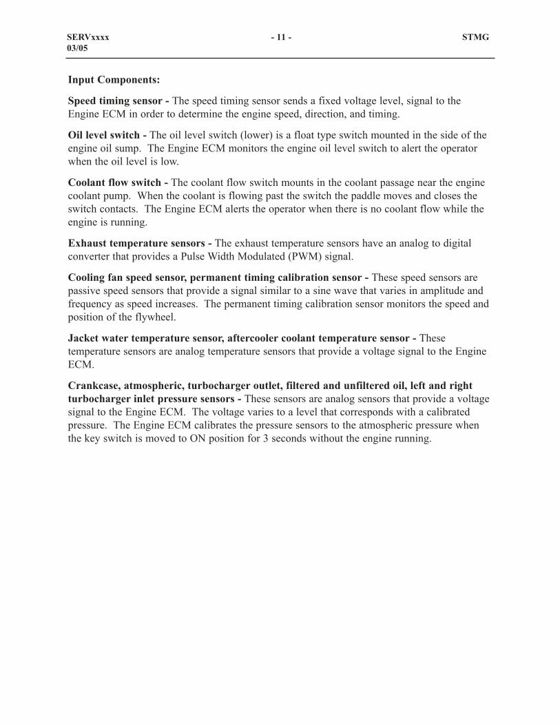
Throttle Lock Circuit
The Throttle Lock feature is very similar to a cruise control system used on automotive andtruck applications. The main difference is that this system uses engine speed as its referenceinstead of vehicle speed. Therefore, engine speed is maintained, unlike other applicationswhich control ground speed.
The Throttle Lock control is within the ECM. The other components are:
- Throttle Lock Enable Switch
- Set/Deceleration Switch
- Resume/Acceleration Switch
- Right Brake Pedal Switch
- Throttle Lock lamp does not communicate with the engine ECM. The Throttle LockLamp ON/OFF is controlled by the Throttle Lock Enable Switch.
SERVxxxx - 23 - STMG03/05
��#���.�.�"7�.(/�
���?�#��(��@
�AB�?�3
0��0�"/:�
;�
;;
�
�,
��
�;
� ����� �.�%!�#�����! �<0�=� ����� �.�%!�#�����! �<0"=��������# ���� ����� �.�%!�� �8� %� ��� � ����� �.�%!�# ��� 8(%% � ��� � ����� �.�%!��08���
++C?�#
#������#(7���(.��-��"�
�A;�?�>�A;;?�#
�A�A?>.
�A�C?�3�A�+?�#
++C?�#
++C?�#
++C?�#
++C?�#
++C?�#
��#���.�.�"7
��8�".#(���0��-
��#���.�.�"7
#�3/8("".#(���0��-
��#���.�.�"7��-
��#���.�.�"7�"�#"3��
;BB?�7��#��#�30�
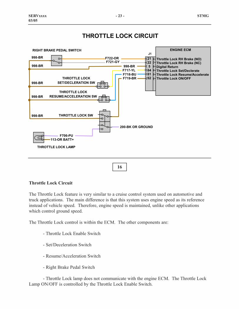
The throttle lock enable switch (1) is located in the dash. The throttle lock switches that aremounted in the cab to the right of the operator's seat are the set/decelerate (2) and theresume/accelerate switch (3).
Also shown are button (4) for the horn and control levers (5)
17
18
SERVxxxx - 24 - STMG03/05
1
2
3
4
5
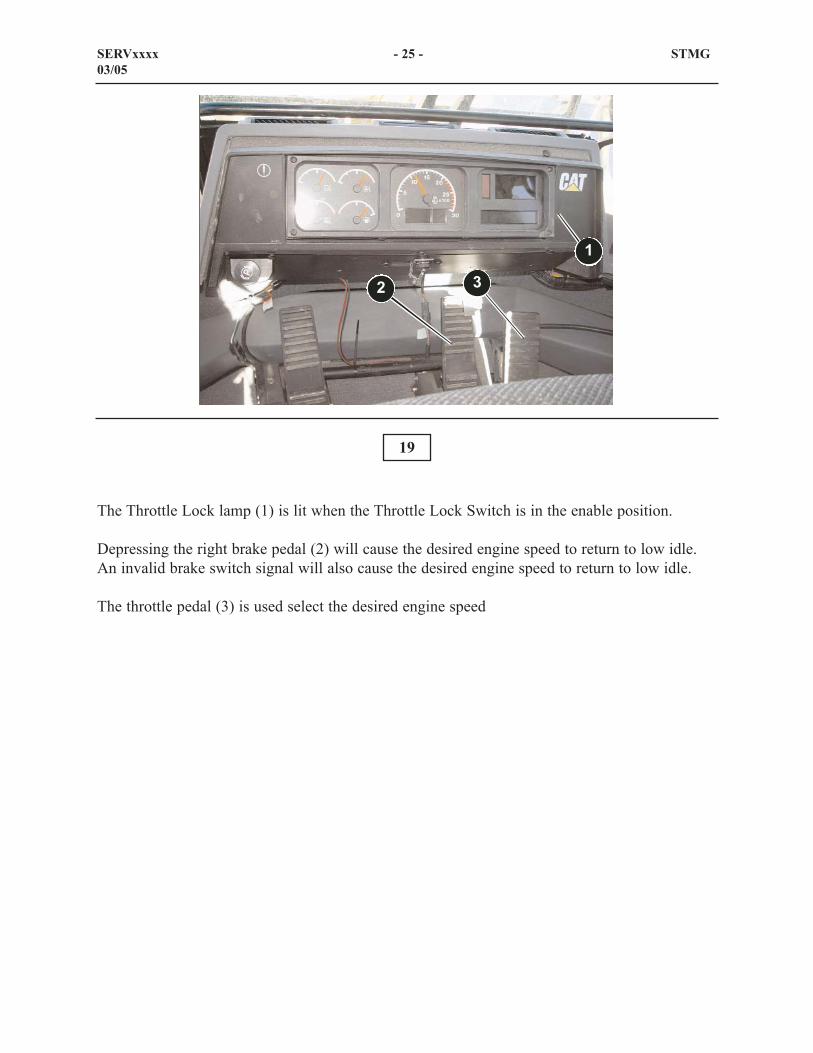
The Throttle Lock lamp (1) is lit when the Throttle Lock Switch is in the enable position.
Depressing the right brake pedal (2) will cause the desired engine speed to return to low idle.An invalid brake switch signal will also cause the desired engine speed to return to low idle.
The throttle pedal (3) is used select the desired engine speed
19
SERVxxxx - 25 - STMG03/05
1
2 3

20
The 994F derates for the 3516B HD Engine are as follows:
- Exhaust Temperature Derate
- Altitude Compensation Derate
- Air Inlet Restriction Derate
SERVXXXX - 26 - STMG03/05
���������0��0��#(��
D��(�����& �"��� �����
D��) ������ �� �����
D��(����� ��# ����%���
21
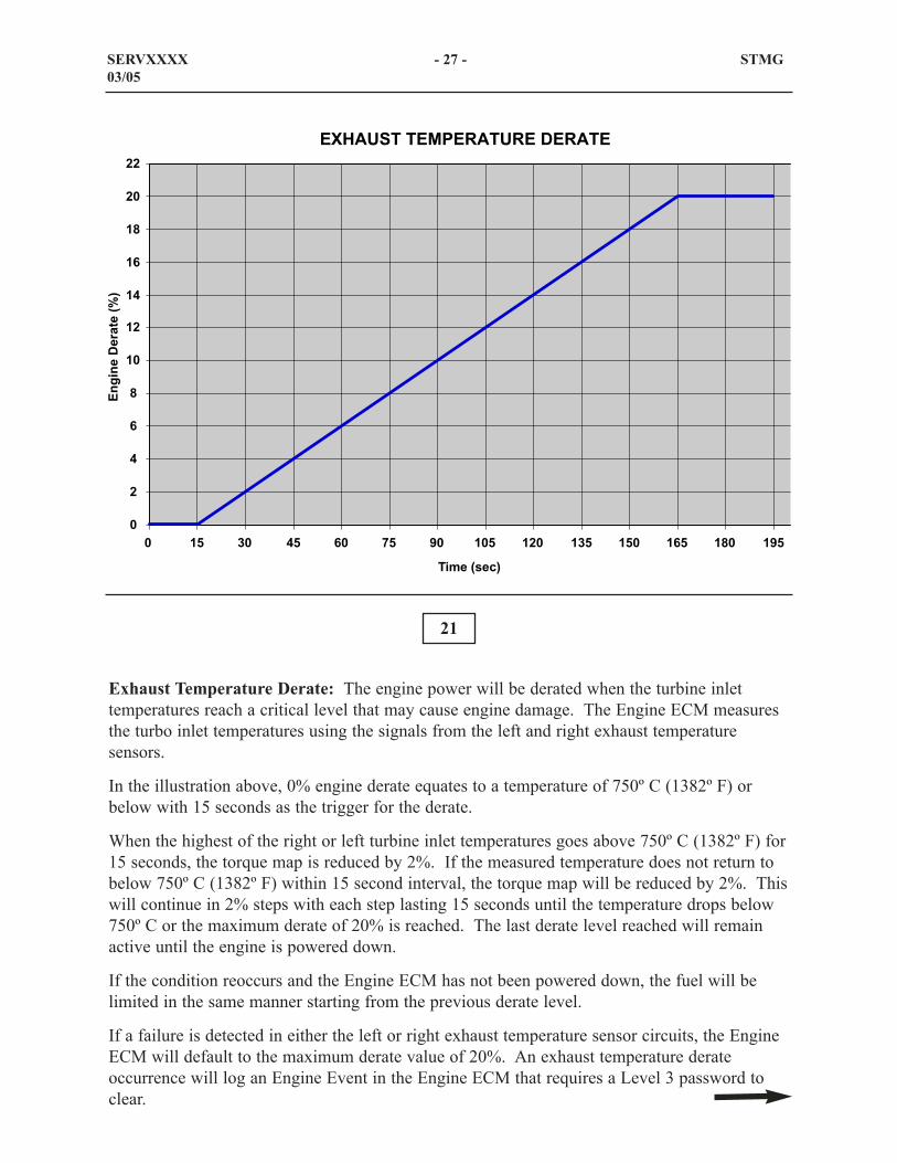
Exhaust Temperature Derate: The engine power will be derated when the turbine inlettemperatures reach a critical level that may cause engine damage. The Engine ECM measuresthe turbo inlet temperatures using the signals from the left and right exhaust temperaturesensors.
In the illustration above, 0% engine derate equates to a temperature of 750º C (1382º F) orbelow with 15 seconds as the trigger for the derate.
When the highest of the right or left turbine inlet temperatures goes above 750º C (1382º F) for15 seconds, the torque map is reduced by 2%. If the measured temperature does not return tobelow 750º C (1382º F) within 15 second interval, the torque map will be reduced by 2%. Thiswill continue in 2% steps with each step lasting 15 seconds until the temperature drops below750º C or the maximum derate of 20% is reached. The last derate level reached will remainactive until the engine is powered down.
If the condition reoccurs and the Engine ECM has not been powered down, the fuel will belimited in the same manner starting from the previous derate level.
If a failure is detected in either the left or right exhaust temperature sensor circuits, the EngineECM will default to the maximum derate value of 20%. An exhaust temperature derateoccurrence will log an Engine Event in the Engine ECM that requires a Level 3 password toclear.
SERVXXXX - 27 - STMG03/05
B
;
,
�
C
�B
�;
�,
��
�C
;B
;;
B �� �B ,� �B A� +B �B� �;B ��� ��B ��� �CB �+�
��� �<� %=
�� �� ��� �<E=
5�(3����/�#(�3#��#(�

22
Altitude Compensation Derate: The Engine ECM derates engine power according tooperating altitude in order to reduce exhaust temperatures. The engine ECM calculates theoperating altitude of the machine based on the signal received from the atmospheric pressuresensor.
The Engine ECM derates the engine power approximately 3% per 305 m (1000 ft) when themachine is operated above 3050 m (10,000 ft). The maximum altitude derate for the engine is24% at 5180m (17,000 ft).
Altitude compensation derate does not log an event in the Engine ECM.
SERVXXXX - 28 - STMG03/05
B
�
�
+
�;
��
�C
;�
;,
;A
�B
��
��
�+
� ; � , � � A C + �B �� �; �� �, �� �� �A �C �+ ;B ;� ;; ;�
����������F��BBB�������(.���3�
�� �� ��� �<E=
(.���3��"�/�0�(���0��#(�
B

23
Air Inlet Restriction Derate: The Engine ECM derates engine power when the air inlet orfilter becomes plugged and restricts air available for combustion resulting in elevated exhausttemperatures. The above illustration shows the engine derates in relation to the air inletrestriction.
The Engine ECM determines inlet air restriction by subtracting the turbocharger inlet airpressure that is measured by the turbocharger inlet air pressure sensors from the atmospheric airpressure.
The Engine ECM derates the power by 1% when the inlet air restriction reaches 6.5kPa (25inches of water). The engine will default to a maximum derate of 20% if the Engine ECMdetects a fault in the circuits for the left or right turbocharger inlet pressure sensors or theatmospheric pressure sensor.
An air inlet restriction event will be logged in the Engine ECM when the engine starts derating.A password is not required to clear an air inlet restriction event.
NOTE: Multiple engine derate percentages can add up and result in a total engine power derategreater than 20%.
SERVXXXX - 29 - STMG03/05
B�;�,��AC+�B���;���,�����A�C�+;B;�;;;�;,;�
B � ; � , � � A C + �B �� �; �� �, �� �� �A �C �+ ;B
�� ��# ����%����<!��=
�� �� ��� �<E=
(�#���.�#�#��#�"���0��#(�

24
COOLING SYSTEM
This illustration shows the flow of the engine coolant through the radiator, the engine, the oilcoolers, and the Separate Circuit After Cooler (SCAC) coolant through the after coolers.
The 994F has been updated with Next Generation Modular Radiator (NGMR) cores for theengine coolant and the SCAC.
Hot engine coolant from the engine enters the half of the bottom tank that is closest to the rearof the machine. The coolant flows up through the dual pass radiator cores, then down throughthe same cores and enters the half of the bottom tank nearest the engine after it has been cooled.
The main coolant pump draws the cooled engine coolant from the radiator, or the regulatorhousing when the regulators are in bypass, and sends it through the engine oil cooler, the brakeoil cooler, the power train oil cooler, and then into the engine block. The engine coolant flowsthrough the engine coolant passages and exits the engine block through the regulator housing.
SERVxxxx - 30 - STMG03/05
���� ��
"��& ��
�����"("�"�����
�%� ����"�����
� �� ����� ��* ����������"��� �
�� ���
"��� �
/��"���������
(�)G�"���������
# �������������
(�� �%��� ��
�� �"�����#�&�����
� ����� �"��%���(�� �%��� ��<�"("=
#�&�����
++,��0��0�"��.�0���>��/05���0#(���0�/��3.(#�#(��(��#�<0�/#=
���! ����"��� �
��� %������(������*
��� %������(������*
#�&������'����

The engine coolant regulators open and allow the engine coolant to bypass the engine radiatorsand flow to the main coolant pump inlet when the engine is cold. The regulators close anddirect engine coolant to the radiator when the engine reaches operating temperature. Theengine coolant regulators and radiator bypass circuit allow coolant flow through the engine andcoolers when the engine is below operating temperature.
The auxiliary coolant pump pulls the coldest coolant from the SCAC radiator cores and sends itto the aftercoolers. The coolant flows through the aftercoolers in series and then returns to theSCAC radiator cores.
The SCAC radiator cores are NGMR radiator cores. The hot coolant enters the split bottomtank and flows up through the tube in the dual pass radiator cores nearest the back of themachine. The coolant then flows down through the same cores to the half of the bottom tanknearest the engine after it has been cooled.
The brake oil cooler has not changed and is mounted below the engine on the inside of the leftrear frame rail. The brake oil cooler is an oil to water cooler and cools the oil from the brakecooling circuit not the brake application hydraulic oil.
SERVxxxx - 31 - STMG03/05
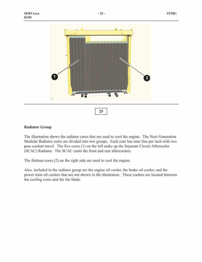
Radiator Group
The illustration shows the radiator cores that are used to cool the engine. The Next GenerationModular Radiator cores are divided into two groups. Each core has nine fins per inch with twopass coolant travel. The five cores (1) on the left make up the Separate Circuit Aftercooler(SCAC) Radiator. The SCAC cools the front and rear aftercoolers.
The thirteen cores (2) on the right side are used to cool the engine.
Also, included in the radiator group are the engine oil cooler, the brake oil cooler, and thepower train oil coolers that are not shown in the illustration. These coolers are located betweenthe cooling cores and the fan blade.
25
SERVxxxx - 32 - STMG03/05
1 2

26
Air Start System
This illustration shows the location of the engine air start components on or near the the rearframe.Components that can be seen include:
- Air dryer (1)- Air horns (2)- Air start tank (3)- Air horn solenoids (4)- Air compressor (5)- Air start motor (6)- Air start solenoid (7)- Air relay (8)- Gauge (service fill) (9)- Socket (service fill) (10)
SERVXXXX - 33 - STMG03/05
1
2
3
45
6 7 89
10

This illustration shows the air engine starter (1) and the air starter solenid valve (2). This photoshows the air engine starter from under the machine on the right side. The air engine startersolenoid valve receives starting current from the Power Train ECM (not shown).
27
SERVxxxx - 34 - STMG03/05
12

28
Air Start System
This illustration shows the air start tank charged with air pressure and the solenoids de-energized. The engine air start system supplies the required amount of air to turn the air startmotor and will in turn start the engine.
At initial start up, the air start tank is bled down, or through leakage the air tank will need to becharged. The socket that is located in the service fill area is used to provide the required air topressurize the tank. The air from the socket flows around the air dryer and into the air tank. Atthis time, the air in the tank will charge the line going to the relay valve. Also, air flows to theair horn solenoids, the gauge, the air start solenoid, and to the unloading valve on the aircompessor. When the air compressor has fully charged the tank and the lines, the unloadingvalve will signal the air compressor to stop.
The pressures switch communicates with contact J1-13 on the VIMS module.
If the pressure on the unloading line (between the air tank and the air compressor) decreases,the unloading valve will signal the compressor to resume supplying air for the air tank.
At this time, no air pressure is directed to the air start motor or to the air horns.
SERVXXXX - 35 - STMG03/05
�� ����
�*��%
�� ����
���� %� ��
1���
(��
����� ���!
(��������
��� ��&
(��
"���� ����
(�����' �
����
# ��'
1���
(��
����� �/����
��%! �
� ���% �����< =
�����1���
� ���% < ����=
" %!�1���
++,��-�.�.�(�#�0��0�(�#���(#���>��/
(������
# ��'
(������
# ��'
��.0�����0���0#��H�

29
Air Start System
This illustration shows the air start tank charged with air pressure and the air start solenoidenergized. When the engine start switch is turned to the ON position, a signal is sent to thePower Train ECM. Then, the Power Train ECM sends a voltage signal to the coil on the airstart solenoid to open and allow air to pass through the solenoid valve. The air will flowthrough the air solenoid valve and flow to the air start motor. The pinnion (not shown) willmove into the fly wheel. Then, the air flows to the relay valve to signal the relay valve to openand allow air to flow directly from the tank to the air start motor. When the engine is started,release the key and the Power Train ECM will de-energize the air start solenoid valve. Also,the Power Train ECM will de-energize the air start solenoid valve when the ECM gets a signalthat the engine is rotating at least 400 rpm for 10 seconds.
SERVXXXX - 36 - STMG03/05
�� ����
�*��%
�� ����
���� %� ��
1���
(��
����� ���!
(��������
��� ��&
(��
"���� ����
(�����' �
����
# ��'
1���
(��
����� �/����
��%! �
� ���% �����< =
�����1���
� ���% < ����=
" %!�1���
++,��-�.�.�(�#�0��0�(�#���(#���>��/
(������
# ��'
(������
# ��'
(�#���(#����.0����0#��H�

30
The air start system is equipped with a socket (2) in the service fill bay to charge the air starttank for an initial startup or in the case of a air leak. The service bay is equipped with a gauge(1) for checking the air pressure in the air start tank.
SERVXXXX - 37 - STMG03/05
1
2

There are several parameters that are monitored to determine if it is appropriate to inject oil. Ifany of these are not true then operation of the ORS strategy is halted until all conditions aremet or the ECM power is recycled.
The parameters that are monitored are as follows:
- Engine Speed – must be greater than 1100 rpm. If engine speed exceeds 1100 rpm, oilwill be injected at the end of the 5 minute sampling period.
- Engine must be running for 5 minutes
- Coolant Temperature – must be between 63°C and 107°C before ORS start up
- Coolant Temperature sensor fault check (open or short to ground)
- Oil pressure sensor fault check (open or short to ground)
- Oil pressure Event check (active or inactive)
- Fuel Level must be equal or greater than 10%
- Fuel Level sender fault from VIMS
- Engine Oil Level Status
The following callouts are locations of the components for the Oil Renewal System.
- Renewal tank (1)
- Metering valve (2)
- Service fill (3)
SERVXXXX - 38 - STMG03/05

31
Oil Renewal System (ORS)
The Oil Renewal System (ORS) is intended to increase the time between oil changes withoutshortening the life of the engine. Also, the system will decrease the amount of oil to bedisposed of. The ORS removes used engine oil from the engine sump and meter that oil intothe fuel return line. The used oil wil be consumed by the engine during the normal process ofcombustion.
Normal Oil Analysis will determine whether the engine oil should be changed.
The Oil Renewal System is an integrated system that requires the installation of additional iron.The Engine ECM monitors fuel rate for 5 minutes to determine an approximate fuel usage.For the next 5 minutes, oil is injected from the crankcase into the engine’s fuel return line basedon the amount of fuel that is burnt. The target concentration for this operation is approximately0.5% oil to fuel. When the fuel tank is filled, the oil concentration will be below target. Whenthe fuel tank is low, the oil concentration will be above target. It should be noted that themonitoring of fuel usage and the injection of oil would be taking place simultaneously with thecorresponding oil injection lagging by 5 minutes.
SERVXXXX - 39 - STMG03/05
1 2
3

32
The Oil Renewal System is filled at the service fill that is located on the right side of the engineend frame (EEF) near the articulation hitch. The tank filler (1) is used in order to fill therenewal tank (not shown). LED (2) will light when the upper level switch in the renewal tank(not shown) is activated. Access the tank filler by openning the cover over the service fill (Theillustration show the cover removed).
SERVXXXX - 40 - STMG03/05
1
2

33
The renewal tank holds oil that will eventually be metered into the engine sump. The tank isequipped with two level switches. The upper level switch (2) is used to illuminate the blueLED that is in the service fill. The lower level switch (3) communicates with the VIMSmodule giving a signal that the renewal tank is empty. VIMS does display a warning sayingORS OIL LVL LO but does not instruct the operator to take any action.
NOTE: The Oil Renewal System will not be shut down until the upper level switch for theengine oil sump shows a low level event.
SERVXXXX - 41 - STMG03/05
1
2
3

The metering valve draws oil from the engine oil sump and sends that oil to to the fuel returnline and eventually to the fuel tank. At the same time, the engine oil sump is back filled withnew oil from the renewal tank.
34
34A
SERVXXXX - 42 - STMG03/05

35
Variable Clutch Fan Control
The variable clutch fan control is use to meet the changing cooling requirements, thus reducingthe horsepower that is used to drive the fan in cooler ambients or light duty cycle workconditions. The Rockford fan controls and limits fan speed by proportally modulating engineoil pressure to the clutch.
The speed of the fan will increase or decrease to compensate for a temperature change throughfeedback from the temperature sensors. The Engine ECM receives feedback from threesensors: the hydraulic oil temperature sensor, coolant temperarture sensor, and the aftercoolertemperature sensor. Each sensor has a target temperature programmed into the ECM. Whenone or more of the sensors read a temperture above the key target temperature, the ECM willsend a signal voltage to the solenoid valve to increase the flow of engine oil through the valveresulting in an increase in pressure to the variable clutch. At the same time, the speed sensorwithin the clutch assembly will monitor the speed of the fan and send feedback to the EngineECM that the fan is rotating at the necessary speed.
SERVXXXX - 43 - STMG03/05
1
2
3
4

The following is a list of components in the variable clutch fan control.
- Fan clutch (1)
- Control valve (2)
- Engine oil pressure supply port (3)
- Return to the engine sump port (4)
SERVXXXX - 44 - STMG03/05

36
SERVXXXX - 45 - STMG03/05
�� �����
���"���%
��������������� ��&�1���
���� ������ ���� �����
�� ���������
�����"���(�� �9�'
1(#�(�.�".3�"���(0��>��/����#�3"���0

37
POWER TRAIN
Power Flow
Power from the diesel engine is sent from the flywheel through the spring coupling to the rearpump drive. The rear pump drive is splined to the torque converter. Other components (notshown on this illustration) that are driven by the rear pump drive are: the two steering pumps,the brake actuation pump, the brake cooling pump, and the steering cooling pump.
Two universal joints and the input drive shaft connect the torque converter to the transmissioninput transfer gear.
The input transfer gear is splined to the transmission input shaft. The transmission output shaftis splined to the output transfer gear. Power from the output transfer gear is sent through thefront drive shaft and it’s respective pinion, bevel gear, differential carrier, and axles to the frontfinal drives and similarly to the rear final drives.
SERVxxxx - 46 - STMG03/05
++,���-�.�.�(�#��-#��#(�0���-#��.�-
�����
�����
����������
����
���� ����
����
����������
����
����
����� �
� ��
����
� ���
���!��
���!
�����"������
# ��
����
����
���$�
"�� �� �����
����
� ���
� %�&��'
�� ������
����������
���� ��
������
����� �
� ���
����������
����"��� ��

38
Power Train Electrical System
This illustration of the Power Train Electrical System shows the components which provideinput signals to the Power Train ECM.
Based on the input signals, the Power Train ECM energizes the appropriate transmission controlvalve solenoids for speed and directional clutch engagement. The Power Train ECM alsoenergizes the starter relay when starting the machine and the back-up alarm when the operatorselects a reverse gear.
When required, the Power Train ECM energizes the impeller clutch control valve solenoid, thelockup clutch control valve solenoid, and the reduced rimpull indicator lamp.
The CAT Data Link connects the Power Train ECM to the Engine ECM. The data link alsoconnects the ECMs to the Vital Information Management System (VIMS) and electronic servicetools such as Caterpillar Electronic Technician (ET).
SERVXXXX - 47 - STMG03/05
��%!?���(����# ��'
�� ����8�����������.�%!��*��%
"���% ����&�� ������ ��&
.�%!���"���% ��� ��&
��� �� ��"���% ��� ��&
"���% �,;&�� ������ ��&
"���% ������� ������ ��&
"���% �;���*��&���� ��&
"���% ��# � �� ���� ��&
"�������&�/������'�� ��
��* �����"/
# &�% &�#�������&�%�����.���
# &�% &�#������� � %�����*��%
���!������! �� ���� ��*��%
.�%!���"���% �9� ��*��%
���$� �"�� �� ��� &������������ ���
(����������� ��&
���"3�� ���I���*� ���I���*��&I�0 �����I
# � ��
7 '��������*��%
���$� �"�� �� ���������� &�� ���
������������������� &�� ������2�;
��� �� ��"���% �� ���� �� ���
"��������.�!
�0�3��"�/��00�� �3��3��"�/��00��
��-#��#(�0
."�#�"(.��>��/�
�� ��� &�� ���
(����.�9 ��� ��&
(����.�9 �� ���� �� ���
���� ������������.�%!�����*��%
���� ������������.�%!����.�
���!������! ���������*��%

Power Train ECM Inputs:
STIC: Combines control of the vehicle steering system and the transmission shifting system ina single input device.
Key Start switch: Provides a signal to the Power Train ECM when the operator wants to startthe engine. The STIC directional switch must be in the NEUTRAL position before the PowerTrain ECM will permit engine starting.
Reduced rimpull selection switch: When enabled by the reduced rimpull enable switch, thisrotary switch determines the maximum rimpull torque.
Park brake pressure switch: Monitors the park brake hydraulic pressure and the Power TrainECM can determine when pressure is applied to release the park brake.
Parking Brake Position Switch: Provides an input the Power Train ECM to signal whetherthe parking brake is engaged or disengaged.
Lockup clutch enable switch: When in the ON position, enables the lockup clutch toENGAGE when the machine operating conditions are correct. The lockup clutch enable lampis turned on by electrical contacts in the switch whenever the lockup clutch is enabled..
Steering and transmission lock switch: When in the LOCK position, causes the Power TrainECM to shift the transmission to NEUTRAL.
Torque converter pedal position sensor: Signals the position of the torque converter pedal tothe Power Train ECM. The Power Train ECM uses the position information to vary torque tothe drive train through the impeller clutch. The actual value of torque reduction is determinedby a combination of different input signals.
Torque converter speed sensor: Provides a signal the Power Train ECM uses to determinethe output speed and direction of the torque converter.
Transmission speed sensors: Provides a signal the Power Train ECM uses to determine theoutput speed of the transmission.
Impeller clutch pressure sensor: Provides a pulse width modulated signal the Power TrainECM uses to determine the impeller clutch hydraulic pressure.
Bumper Transmission Lockout Switch: Provides a ground level input the Power Train ECMthat will neutralize the transmission until the switch is moved to the UNLOCK position.
Engine Speed Sensor: A magnetic switch input that provides the engine speed to the PowerTrain ECM.
Auto Lube Pressure Sensor: Provides a signal the Power Train ECM to determine the statusof the pressure disengage the
SERVxxxx - 48 - STMG03/05

Power Train ECM Outputs:
Air Start Solenoid: The Power Train ECM energizes the air start solenoid valve when theappropriate conditions to start the machine have been met.
Reduced rimpull indicator lamp: The Power Train ECM illuminates the reduced rimpullindicator lamp when the appropriate machine operating conditions are met and the Power TrainECM is providing reduced rimpull.
Clutch solenoids: The solenoids control oil flow to the speed and directional control spools.
Impeller clutch solenoid: The Power Train ECM energizes the impeller clutch modulatingvalve in order to control hydraulic pressure to the impeller clutch.
Lockup clutch solenoid: The Power Train ECM energizes the lockup clutch modulating valvein order to control pressure to the lockup clutch when the correct machine conditions have beenmet.
Back-up alarm relay: The Power Train ECM energizes the back-up alarm when the operatorselects the REVERSE direction with the STIC. The backup alarm relay energizes the twobackup alarms.
Auto Lube Solenoid: The energizes the auto lube solenoid for the next lube cycle.
Bumper Transmission Lockout LED: The Power Train ECM illuminates the bumpertransmission lockout LED when the bumper transmission lockout switch is in the LOCKEDposition.
SERVXXXX - 49 - STMG03/05

Power Train Electronic Control Module (ECM)
The Power Train ECM (1) is located on the left side of the machine under the door on theplatform (cover must be removed).
The Power Train ECM makes decisions based on control program information in memory andswitch and sensor input signals.
The Power Train ECM responds to machine control decisions by sending a signal to theappropriate circuit which initiates an action. For example, the operator selects an upshift usingthe STIC. The Power Train ECM interprets the input signals from the STIC, evaluates thecurrent machine operating status and energizes the appropriate solenoid valve.
The Power Train ECM receives three different types of input signals:
1. Switch input: Provides the signal line to battery, ground, or open.
2. PWM input: Provides the signal line with a square wave of a specific frequency and avarying positive duty cycle.
3. Speed signal: Provides the signal line with either a repeating, fixed voltage level patternsignal or a sine wave of varying level and frequency.
39
SERVXXXX - 50 - STMG03/05
1
The Power Train ECM has three types of output drivers:
1. ON/OFF driver: Provides the output device with a signal level of +Battery voltage(ON) or less than one Volt (OFF).
2. PWM solenoid driver: Provides the output device with a square wave of fixedfrequency and a varying positive duty cycle.
3. Controlled current output driver: The ECM will energize the solenoid with 1.25 ampsfor approximately one half second and then decrease the level to 0.8 amps for theduration of the on time. The initial higher amperage gives the actuator rapid responseand the decreased level is sufficient to hold the solenoid in the correct position. Anadded benefit is an increase in the life of the solenoid.
The Power Train ECM controls the transmission speed and directional clutches and theoperation of the impeller clutch and lockup clutch. The Power Train ECM interprets signalsfrom the STIC, the torque converter pedal position sensor, the lockup clutch enable switch, andthe current machine operating status to determine the appropriate output signals to the systems.Different conditions of the inputs affect the output conditions. These conditions will bediscussed later.
The Power Train ECM communicates through the CAT Data Link. The CAT Data Link allowshigh speed proprietary serial communications over a twisted pair of wires. The CAT Data Linkallows different systems on the machine to communicate with each other and also with servicetools such as Caterpillar Electronic Technician (ET).
The Power Train ECM has built-in diagnostic capabilities. As the Power Train ECM detectsfault conditions in the power train system, it logs the faults in memory and displays them onthe VIMS. The fault codes can also be accessed using the ET service tool. VIMS software canbe used to view faults logged by the VIMS.
INSTRUCTOR NOTE: Power Train ECM faults displayed on the VIMS relating to thePower Train ECM will have a Module Identifier (MID) of "81." For additionalinformation, refer to the Service Manual module "994F Wheel Loader Power Train,Troubleshooting, Testing and Adjusting" (Form RENR6306).
SERVXXXX - 51 - STMG03/05

The STIC (1) is bolted to the seat at the front of the left armrest. The transmission directionalcontrol switch (2) is a three position rocker switch that the operator uses to select NEUTRAL,FORWARD, or REVERSE. The transmission speed upshift switch (3) and the transmissionspeed downshift switch (4) are momentary contact switches that the operator uses to select thedesired speed.
When the operator selects REVERSE by depressing the top of the directional control switch,the Power Train ECM energizes the reverse directional solenoid. The Power Train ECM alsoactivates the back-up alarm. When the operator selects FORWARD by depressing the bottomof the directional control switch, the Power Train ECM energizes the forward directionalsolenoid.
When the operator selects NEUTRAL by placing the directional control switch in the centerposition, the Power Train ECM de-energizes both the forward and the reverse directionalsolenoids. After two seconds, the Power Train ECM energizes speed solenoid No. 3 and thetransmission is in NEUTRAL until the operator selects a different gear.
When the operator presses the upshift switch, the Power Train ECM energizes the appropriatespeed clutch solenoid to select the next higher gear, and the transmission upshifts. When theoperator presses the downshift switch, the Power Train ECM energizes the appropriate speedclutch solenoid to select the next lower gear, and the transmission downshifts.
The switches must be released and pressed again to continue shifting. If the operator pressesand holds the upshift or the downshift switch, the transmission will shift once and remain inthat speed until the switch is released and pressed again.
40
SERVXXXX - 52 - STMG03/05
1
2
34
5
6

When the steering and transmission lock lever (5) is moved to the LOCK position (not shown),the STIC is held in the center position and steering is disabled. In the LOCK position, thesteering lock lever depresses the steering and transmission lock switch (not visible). Thesteering and transmission lock switch signals the Power Train ECM to shift the transmission toNEUTRAL.
When the steering and transmission lock lever is moved to the UNLOCK position, the steeringand transmission functions are enabled.
The power train portion of the STIC sends input signals to the Power Train ECM. Certainmachine operating conditions will override the operator desired function of the STIC. If thedirectional switch is in the FORWARD or REVERSE position when the steering andtransmission lock lever is moved to the UNLOCK position, the Power Train ECM will not shiftfrom NEUTRAL. The directional switch must first be moved to the NEUTRAL position, thento the direction desired before the Power Train ECM will engage a directional clutch.
Also shown, is the push/pull parking brake control (6).
SERVXXXX - 53 - STMG03/05

Reduced Rimpull Selection Switch
The Power Train ECM reduces rimpull by increasing the current to the impeller clutchsolenoid, which reduces the hydraulic pressure to the impeller clutch and allows slippagebetween the impeller and the torque converter housing. By additionally decreasing the impellerclutch pressure, the impeller will slip more resulting in lower torque to the power train. Theresulting additional engine horsepower can be used for the implements.
The reduced rimpull selection switch (1) has four positions. Each position corresponds to amaximum allowable percentage of maximum rimpull. The default values for each position areindicated as follows:
Maximum Rimpull (2) 85% Rimpull (3) 70% Rimpull (4) 55% Rimpull (5)
41
42
SERVXXXX - 54 - STMG03/05
1
2
3
4
5

The operator turns the key start switch (1) clockwise to signal the Power Train ECM to start theengine. The key start switch supplies a signal of +Battery to the Power Train ECM. The PowerTrain ECM energizes the air start solenoid and the air start solenoid supplies air to the startingmotor and begin engine cranking. In order to start the engine, the following conditions must bemet before the Power Train ECM will energize the air start solenoid:
1. The key switch is turned to the start position.
2. The transmission directional control switch is in neutral.
3. The system voltage is below +32 Volts.
4. Engine prelube is complete (if equipped).
If the machine is equipped with the optional engine prelubrication the Power Train ECM willrequest prelubrication status from the Engine ECM via the datalink. If the Engine ECMdetermines the need for prelubrication, the Engine ECM will perform the prelubricationfunction and signal the Power Train ECM when prelubrication has been completed.
43
SERVXXXX - 55 - STMG03/05
1

The Power Train ECM monitors the position of the torque converter pedal (1) with the torqueconverter pedal position sensor (2) located behind the panel at the pivot for the pedal. As theoperator depresses the pedal, the Power Train ECM increases the current to the impeller clutchsolenoid and reduces the hydraulic pressure to the impeller clutch. The rimpull will decreasewith pedal travel from the reduced maximum setting to the minimum setting. When theoperator releases the left pedal, the rimpull will return to the maximum percentage as set by thereduced rimpull selector switch (not shown).
When the maximum allowable percentage is in the lower values, the total change of rimpullfrom maximum to minimum is decreased. This condition results in a more gradual change ofrimpull over the travel of the torque converter pedal.
If the machine is not in FIRST GEAR, the impeller clutch pressure will remain at the maximumlevel until the transmission is shifted into FIRST GEAR.
The torque converter pedal functions similarly when the maximum rimpull selector switch is inthe maximum position, except the maximum allowable percentage is now 100%.
NOTE: An increase in current to the impeller clutch solenoid from the Power Train ECMresults in a decrease in pressure to the impeller clutch.
INSTRUCTOR NOTE: To change the setting for each position of the reduced rimpullselection switch, refer to the Service Manual module "994F Wheel Loader Power Train,Troubleshooting, Testing and Adjusting" (Form RENR6306).
44
SERVXXXX - 56 - STMG03/05
1
2

The impeller clutch modulating valve (1) is located on the left side of the torque converterhousing (3).
The Power Train ECM (not shown) monitors the status of the impeller clutch solenoid and candetermine certain faults that may affect operation of the impeller clutch. These faults include:a short to +Battery, a short to ground, an open circuit, or the impeller clutch not respondingproperly.
The Power Train ECM receives a signal from the impeller clutch pressure sensor (5) to monitorthe impeller clutch pressure. The Power Train ECM can compare the control of the impellerclutch solenoid with the response of the impeller clutch pressure to determine if the impellerclutch is responding properly.
45
46
SERVXXXX - 57 - STMG03/05
1
3
4 5
2
6

When a fault is detected, controlled throttle shifting is used. When a directional shift is madeabove 1100 rpm, the Power Train ECM will request a desired engine speed of 1100 rpm fromthe Engine ECM for 1.9 seconds if shifting into forward and a desired engine speed of 1100rpm for 2.5 seconds if shifting into reverse. This feature helps decrease the energies absorbedin the transmission.
When the Power Train ECM detects a fault in the impeller clutch solenoid circuit, a fault willbe displayed on the VIMS message center (not shown).
The torque converter pedal position sensor (not shown) and the impeller clutch solenoid mustbe calibrated through the VIMS to ensure proper operation.
Also shown are the lockup clutch solenoid (2) and the lockup clutch valve. The lockup clutch solenoid and lockup clutch valve look similar to the impeller clutchsolenoid and impeller clutch valve but are different and should not be interchanged.
The lockup clutch solenoid is mounted on the lockup clutch valve. The lockup clutchmodulating valve is located on the left side of the torque converter housing between theimpeller clutch solenoid valve and the torque converter housing.
The Power Train ECM energizes the solenoid for the lockup clutch in order to allow oil to flowto the lockup clutch. The pressure increases in the lockup clutch, causing it to engage and themachine operates in DIRECT DRIVE.
The solenoid for the lockup clutch is a proportional solenoid and is energized by a modulatedsignal from the Power Train ECM. The Power Train ECM varies the amount of current tocontrol the amount of oil flow through the lockup clutch valve to the lockup clutch.
The Power Train ECM receives a signal from the torque converter output speed sensor (4). Thespeed sensor is mounted on the front of the torque converter housing above the output shaft.The signal is a fixed voltage level, patterned waveform which the Power Train ECM uses todetermine the speed and direction of the torque converter output.
If the machine is allowed to roll backwards on an incline when a forward gear is selected thetoque converter output can turn in reverse . This condition is called reverse turbine and canresult in high temperatures inside the torque converter. If the Power Train ECM determines theoutput of the torque converter is turning in the reverse direction greater than 500 rpm, thePower Train ECM will ignore the left pedal position input and increase the impeller clutchpressure to prevent this condition. The Power Train ECM will also override the reducedrimpull setting if necessary to try to eliminate the reverse turbine.
The Power Train ECM monitors the temperature (6) of oil exiting the torque converter with thetorque converter outlet oil temperature sensor (1) which is mounted on the front right of thetorque converter housing, just above the torque converter outlet relief valve.
INSTRUCTOR NOTE: An increase in current to the lockup clutch solenoid from thePower Train ECM results in an increase in pressure to the lockup clutch.
SERVXXXX - 58 - STMG03/05

The lockup clutch enable switch (1) is located on the right side panel in the cab. When theswitch is in the ON (closed) position and the proper conditions have been met, the Power TrainECM will engage the lockup clutch in order to improve the efficiency of the power train.
The Power Train ECM first sends a signal to the lockup clutch modulating valve to enengagethe lockup clutch to a Hold Level for .75 seconds to allow time for the clutch to fill. Then, thecurrent is ramped up to full ON in .65 seconds.
During normal operation, the Power Train ECM will ENERGIZE the torque converter lockupclutch solenoid based on the following conditions:
1. Lockup clutch enable switch state: ON (closed).
2. Torque converter output speed: When the torque converter output speed is greater than1125 ± 50 rpm.
3. Time in gear: The transmission must be in the present speed and direction for at leasttwo seconds.
4. Time since lockup clutch solenoid was de-energized: At least four seconds must havepassed since the Power Train ECM de-energized the lockup clutch solenoid.
5. Left pedal and right brake pedal status: Both pedals must be fully released.
47
SERVXXXX - 59 - STMG03/05
1

Torque Converter Components
The torque converter is installed on the rear pump drive.
- Impeller clutch modulating valve (2)
- Lockup clutch modulating valve (3)
Impeller clutch pressure is monitored by the Power Train ECM via the impeller clutch pressuresensor (5). The lockup clutch pressure and the impeller clutch pressure is measured at thepressure tap panel along with the respective clutches.
The torque converter output speed and direction is monitored by the Power Train ECM via thetorque converter output speed sensor (4) mounted near the torque converter output shaft (6).The torque converter output speed sensor sends a signal to the Power Train ECM.
The temperature of the torque converter output oil is monitored by the torque converter outputsensor (1). The torque converter output temperature sensor sends a pulse width modulatedsignal to the VIMS control module.
48
SERVXXXX - 60 - STMG03/05
1 2 3
4 5
6

This illustration show the transmission pump that is mounted on the torque converter housingbelow the output shaft on the rear pump drive. The transmission pump has two sections. Thefront section (1) supplies oil to the torque converter. The rear section nearest to the torqueconverter housing (2) supplies oil to the priority valve, then the lockup clutch modulating valve,the impeller clutch modulating valve, and the transmission control valve.
49
SERVxxxx - 61 - STMG03/05
2
1

Transmission Oil Filters
The upper illustrations shows the location of the power train filters (1) in the rear frame of themachine. The transmision filters can be accessed by raising the door on the platform that isbehind the cab. Also shown are the torque converter housing (2) and the transmission (3).
The lower illustration shows both filters. The filter on the left filters oil that is flowing to thepriority valve (not shown). The filter on the right filters oil that is flowing to the torqueconverter.
Both filters are equipped with fluid sampling ports (S O S) (4).
50
51
SERVXXXX - 62 - STMG03/05
12 3
4 4

52
Torque Converter
The Illustration shows a sectional view of the torque converter. The major components includethe rotating housing, the impeller, the turbine, the non free wheel stator, the impeller clutch, andthe lockup clutch.
The rotating housing is splined to the engine flywheel and turns with the flywheel.
When the impeller clutch port is pressurized, the impeller is connected to the rotating housingthrough the impeller clutchengagement. The clutch discs are splined to the impeller. Theclutch plates are splined to the rotating housing. Pressure oil at the clutch piston will engagethe discs and plates. The impeller rotates with the housing.
The turbine is splined to the output shaft. In torque converter drive, the turbine is turned by oilfrom the impeller.
In direct drive, the lockup clutch port is pressurized. The lockup clutch connects the turbine tothe rotating housing. The lockup clutch discs are splined to the turbine. The lockup clutchplates are splined to the rotating housing. Pressure oil moves the clutch piston to engage thediscs and plates. When the clutch is engaged, the turbine, the housing, the impeller, and theoutput shaft rotate as a unit at engine rpm.
SERXXXX - 63 - STMG0305
��#J3�"�01#�#
������
.�%!���"���%
���9�
��� �� �
��� �� ��"���% ������
��� �� ��"���% ����
.�%!���"���% ����
���$� �"�� �� ���������
"���% ����%�
"���% ����%�
"���% ������� ���� "�� �� ������
�������� ���

The input transfer gear (not shown) and the basic transmission remains unchanged.
The planetary power shift transmission (1) has three FORWARD and three REVERSE speeds.Electronic solenoids located in the hydraulic control valve (2) shift the transmission. Thesolenoids are actuated by the Power Train Electronic Control Module (ECM) located in theelectronics bay at the rear of the cab.
The transmission output speed sensor (3) monitors the transmission output shaft. The signal issent to the Power Train ECM. The transmission output speed signal indicates when theclutches have engaged.
The two transmission oil screens located in the front of the output transfer gear housing can beaccessed by removing the covers (4).
Also shown here are the secondary steering pump and diverter valve (5) and the output shaft (6)for the rear drive shaft.
The oil sump for the transmission pump (not shown) is located in the bottom of the outputtransfer gear case (7).
53
SERVXXXX - 64 - STMG03/05
1
23
4
5
6
7

54
This illustration is a sectional view of the impeller clutch solenoid valve.
When the impeller clutch solenoid is DE-ENERGIZED, the spring moves the pin assemblyagainst the ball. The ball blocks the pump flow through the orifice to drain. The oil pressureincreases at the left end of the valve spool and moves the valve spool to the right against thespring. The valve spool blocks the passage between the impeller clutch and drain and opens thepassage between the impeller clutch and the pump. Pump oil flows past the valve spool to theimpeller clutch.
When the impeller clutch solenoid is ENERGIZED, the solenoid moves the pin assemblyagainst the spring and away from the ball. Pump oil flows through the center of the valvespool, through the orifice and past the ball to drain. The valve spring moves the valve spool tothe left. The valve spool blocks the passage between the impeller clutch and the pump andopens the passage between the impeller clutch and drain. Pump flow to the impeller clutch isblocked. The oil in the impeller clutch flows past the valve spool to drain.
SERVXXXX - 65 - STMG03/05
����
���������� �� �
"���%
��� ��&
�
(������
(�� �9�'
����1���
����� ����������% �����
� �������
�/�..#�".3�"�
��.0�����?0#��H�
�/�..#�".3�"�
��.0����0#��H�
�/�..#�".3�"�/��3.(��0��1(.1
����
���������� �� �
"���%
��� ��&
�
(������
(�� �9�'
����1���
����� ����������% �����
� �������

55
This illustration is a sectional view of the lockup clutch solenoid valve.
When the lockup clutch solenoid is DE-ENERGIZED, the force that held the pin assemblyagainst the ball is removed. The pump oil flows through the orifice and past the ball to drain.The spring moves the valve spool to the left. The valve spool opens the passage between thelockup clutch and drain and blocks the passage between the lockup clutch and the pump. Pumpflow to the lockup clutch is blocked. The oil in the lockup clutch flows past the valve spool todrain.
When the lockup clutch solenoid is ENERGIZED, the solenoid moves the pin assembly againstthe ball. The ball blocks pump oil flow through the orifice to drain. The oil pressure increasesat the left end of the valve spool and moves the valve spool to the right against the spring. Thevalve spool blocks the passage between the lockup clutch and drain and opens the passagebetween the lockup clutch and the pump. Pump oil flows past the valve spool to the lockupclutch.
SERVXXXX - 66 - STMG03/05
� �������
����
����
����1���
����� ����������%
��� ��& ��
��.0�����?0#��H�
� �������
����
����
����1���
����� ����������%
��� ��& ��
���.0����0#��H�
���"���%
.�"73��".3�"�
��.0����1(.1
���"���%

56
Tansmisison Hydraulic Control Valve
Modulating relief valve: Limits the maximum clutch pressure.
First and third speed selection spool: Directs oil flow to the No. 5 and No. 3 clutches.
Load piston: Works with the modulation relief valve to control the rate of pressure increase inthe clutches.
Second speed selector spool: Directs oil flow to the No. 4 clutch.
Pressure differential valve: Controls speed and directional clutch sequencing.
Directional selection spool: Directs oil to the FORWARD and REVERSE directional clutches.
Converter inlet ratio valve: Limits the pressure to the torque converter.
Passage to Clutch No. 1: Passage to the port to energize clutch No. 1 (Reverse).
Passage to Clutch No. 2: Passage to the port to energize clutch No. 2 (Forward).
Passage to Clutch No. 3: Passage to the port to energize clutch No. 3. (Third Speed)
Passage to Clutch No. 4: Passage to the port to energize clutch No. 4. (Second Speed)
Passage to Clutch No. 5: Passage to the port to energize clutch No. 5 (First Speed).
SERVXXXX - 67 - STMG03/05
�#(0�/�����0�>�#(3.�"�"�0�#�.�1(.1
/�&������
# �� ��1���
�����&���&��� &
� � %���������
.��&������
;&��� &
� � %���������
�� ����
���� � �����1���
��� %�����
� � %���������
"�� �� ���� �
#�����1���
�;
��
��
������
"���% �0�G��
������
"���% �0�G��
������
"���% �0�G�,
������
"���% �0�G�;
������
"���% �0�G��
�������
���$� �"�� �� ���� �
�����" ��9 �
�����" ��9 �

57
Transmission Hydraulic Control Valve
The transmission hydraulic control valve is shown with the transmission shifted to theNEUTRAL position. Supply oil from the transmission filter is directed to either the solenoidvalve manifolds (not shown) or at the top of the modulating relief valve. The pressure of thesupply oil overrides the check valve (at the inlet). Oil flows through the passage (red) aroundthe modulating valve through the ball check valve and fills the slug chamber (red). Thepressure in the slug chamber will override the spring and the modulating valve will movedownward. As the modulating valve moves downward, oil will flow around the modulatingvalve to the cavity (orange). The oil will flow through the passag (orange) to the port for thetorque converter inlet (not shown).
The supply oil flows through the flow control orifice to the chamber for the 1st and 3rd speedselector spool and the chamber for the 2nd speed spool (in neutral, the speed selector spool willbe shifted in order to direct oil flow to the passage clutch No. 3). Also, the oil flows throughthe passage (red) to the slug chamber of the converter ratio valve and the center of the pressuredifferential valve.
Oil that is flowing from the center of the differential valve through the orifice is directed belowthe load piston.
SERVXXXX - 68 - STMG03/05
�#(0�/�����0�>�#(3.�"�"�0�#�.�1(.1
/�&������
# �� ��1���
����(&���&��� &
� � %���������
.��&������
;&��� &
� � %���������
�� ����
���� � �����1���
��� %�����
� � %���������
"�� �� ���� �
#�����1���
�;
��
��
������
"���% �0�G��
������
"���% �0�G��
������
"���% �0�G�,
������
"���% �0�G�;
������
"���% �0�G��
�����" ��9 �
�����" ��9 �
�������
"�� �� ���� �

Movement of the load piston in the upwards direction, begins the modulating cycle. The oil inthe upper cavity of the differential valve shifts the valve downward against the spring. Whenthe supply oil pressure is at approximately 380 kPa (55 psi) the force that is developed by theoil flow to the center of the differential valve moves the differential valve downward andoverrides the spring. Oil can flow around the differential valve and flow through passage(red/white) to cavity (P2). When the pressure at P2 reaches the 380 kPa (55 psi) differential,the differential valve shift upwards in order to block around the differential valve. The oilpressure at P2 will always be approximately 380 kPa (55 psi) less than the pressure at P1. Thedifferential pressure between P1 and P2 will make sure that the speed clutch will alwaysengage before the direction clutch.
With a directional shift out of neutral, the directional selector spool will be shifted in eitherdirection and oil in cavity (P2) will be directed to one of the two directional clutches (notshown).
SERVxxxx - 69 - STMG03/05

58
This illustration is a sectional view that is showing the transmission planetary group. Theplanatary group is equipped with two directional and three speed clutches.
In this sectional view of the transmision, the input shaft and the input sun gear ar shown in redwith the output shaft and the output sun gears shown in blue. The ring gears are shown ingreen. The planetary carriers are shown in brown while the planetary gears and shafts areshown in orange. The clutch discs, clutch plates, pistons, springs, and bearings are shown inyellow. Stationary components are shown in gray.
Speed Engaged Clutches
First/Forward No. 2 and No. 5
Second/Forward No. 2 and No. 4
Third/Forward No. 2 and No. 3
Neutral No. 3
First/Reverse No. 1 and No. 5
Second/Reverse No. 1 and No. 4
SERVXXXX - 70 - STMG03/05
��� ���'
"���� �
�������
� ���
#��
� ���
����
�� ���
������
� ���
���������
�� ���
#��
�� ��
� ; � ,
�
��-#��������#(0�/�����0

59
Power Train Hydraulic System
This illustration shows the components and the oil flow for the power train hydraulic system inNeutral.
In this schematic, the engine is running and the transmission in neutral. With the transmissiondirection switch in the NEUTRAL position, the Power Train ECM energizes the No. 3 clutchsolenoid. The Power Train ECM also de-energizes the lockup clutch solenoid.
The transmission pump (a two section gear pump) draws oil from the sump (located in thebottom of the transmission transfer case) through three magnetic screens that are located in thesump by the transmission pump.
Oil from the left section of the transmission pump flows through the transmission filter (red) tothe priority valve. From the right side of the priority valve, oil flows to the lockup clutchmodulating valve and to the impeller clutch modulating valve.
During a shift, the priority valve maintains 2205 kPa (320 psi) oil pressure to the lockup clutchmodulating valve and impeller clutch modulating valve. When the transmission is in neutral,the lockup clutch is disengaged. Also, the solenoid for the impeller clutch is de-energized andthe impeller clutch is engaged.
SERVXXXX - 71 - STMG03/05
�
�
;
�
; �
� � ,
���$� "�� �� �
.�9 �?�# �����������
;��.8���<�����=�
����������"������1���
��������������
����
�������������� �
���$� "�� �� ����� �
�������'1���
��� �� ��"���% /�&�������1���
.�%!���"���% /�&�������1���
�#(0�/�����0��>�#(3.�"��>��/03�#(.
,
�������-�� ��"��� �
�������-�� ��"��� �
(����������"��� �
(����������"��� �
.�9 �?�# �����������
;��.8��<�����=�
�����������.�9 ;A��.8���<A�����=
����������% +��.8���<;,����=
.�9 �?������������ ��� �����;�A�.8���<A����=�
.�9 �?������������ ��� ��
���.8���<�,����=�
/�� ��%��%� �
�;
��
�;��.8��<�;����=
��;�.8��<+A����=
;��.8��<�����=
��;�!��<CB����=
�B;�.8��<;A����=
.�9 �?���������� �
���.8���<�����=�
������ ����
.�3�"�� ����
��"�� ����
��

When the transmission pump supply pressure increases above the priority valve setting, thepriority valve opens and sends oil flow to the manifold for clutch solenoid valves No. 2 and 3,the manifold for clutch solenoid valves No. 1, 5 and 4, and the inlet passage for the selector andpressure control valves.
The oil at the clutch solenoid valve manifolds becomes the pilot oil for the transmission speedand directional selector spools.
When the No. 3 clutch solenoid is ENERGIZED, the No. 3 solenoid valve sends pilot oil to theupper end of the first and third speed selector spool. The pilot oil pressure overcomes the forceof the selector valve spring and moves the spool from its center position. Oil from the inletpassage flows through the orifice, past the speed selector spool, and into the No. 3 speed clutch.
When directional solenoids No. 1 and 2 are DE-ENERGIZED, pilot oil is blocked at thedirectional solenoid valves. The directional clutch selector spool spring centers the spool. Oilflow between the direction selector spool and the the directional clutches is blocked.
When the oil requirements of the selector and pressure control valve have been satisfied, theremaining power train pump oil flows to the torque converter.
Oil from right side of the transmission pump is directed to the torque converter filter. Oilflows from the filter and joins with the oil from the selector and pressure control valve. Thecombined oil flows to the inlet of the torque converter. Flow continues through the torqueconverter to either the sump or the power train coolers. Then the oil flows to various lubepoints in the transmission lubrication circuit.
When the transmission is in NEUTRAL, the Power Train ECM disengages the optional lockupclutch. The turbine is disconnected from the rotating housing. No power is transmitted fromthe housing through the turbine.
INSTRUCTOR NOTE: Operation of the modulating relief valve, the torque converterinlet ratio valve, and the pressure differential valve is the same as explained in STMG 421"966D Wheel Loader Part 2--Power Train" (Form SERV1421).
SERVxxxx - 72 - STMG0305

60
In this illustration, the engine is running and the transmission is in 1st speed forward in torqueconverter drive.
Flow from the transmission pump is directed through the transmission filter to the priorityvalve, the impeller clutch solenoid valve, and the lockup clutch solenoid valve. The priorityvalve maintains a minimum oil pressure to the impeller clutch solenoid valve and the lockupclutch solenoid valve during transmission shifts. When the transmission pump supply pressureincreases above the spring setting of the priority valve, the priority valve opens and oil isdirected to the speed manifold and the direction manifold. Also, pump supply oil is directedpast the orifice to the inlet port for the 1st and 3rd speed selector spool and the inlet port for the2nd speed selector spool.
When the operator moves the directional switch and upshift or downshift switch to the 1stspeed forward position, the Power Train ECM energizes the impeller clutch solenoid (theimpeller clutch solenoid will be energized and then de-energized). The solenoid for the lockupclutch is also de-energized. Then, the No. 5 solenoid is energized first and No. 2 solenoid willbe energized next.
SERVXXXX - 73 - STMG03/05
�
�
;
�
; �
� � ,
���$� "�� �� �
.�9 �?�# �����������
;;�.8���<�����=�
����������"������1���
��������������
����
�������������� �
���$� "�� �� ����� �
�������'1���
��� �� ��"���% /�&�������1���
.�%!���"���% /�&�������1���
�#(0�/�����0��>�#(3.�"��>��/��#���������#-(#�
�"�01#�#��#�1
,
�������-�� ��"��� �
�������-�� ��"��� �
(������-�� ��"��� �
(������-�� ��"��� �
.�9 �?�# �����������
;��.8��<�����=�
�����������.�9 ;A��.8���<A�����=
����������% +��.8���<;,����=
.�9 �?������������ ��� �����;A�.8���<A����=�
.�9 �?������������ ��� ��
���.8���<�,����=�
/�� ��%��%� �
�;
��
�;��.8��<�;����=
��;�.8��<+A����=
;��.8��<�����=
��;�!��<CB����=
�B;�.8��<;A����=
.�9 �?���������� �
���.8���<�����=�
������ ����
.�3�"�� ����
��"�� ����
��

When the No. 5 solenoid is ENERGIZED, oil pressure is directed to the lower end of the 1stand 3rd speed selector spool. The force of the oil pressure overcomes the force of the speedselector spool spring, the spool shifts upwards and No. 5 clutch is engaged. The No. 2 solenoidis ENERGIZED, pilot oil is directed to the upper end of the directional selection spool. The oilpressure overcomes the force of the selector spool spring and the spool shifts downward.TheNo. 2 clutch will be engaged.
When the oil requirements of the selector and pressure control valve have been satisfied, theremaining oil combines with the oil from the transmission pump (orange). The combined oilflows to the torque converter. Flow continues through the torque converter through the powertrain coolers to the transmission lubrication circuit.
When the transmission is in NEUTRAL, the Power Train ECM pressurizes the impeller clutchin response to the engine speed. When the engine speed is less than 1100 rpm, the impellerclutch pressure is maintained at a holding pressure of 550 ± 207 kPa (80 ± 30 psi). When theengine rpm increases from 1100 to 1300 rpm, the Power Train ECM increases the impellerclutch pressure from 550 ± 207 kPa (80 ± 30 psi) to 2580 ± 207 kPa (375 ± 30 psi) for onesecond. The Power Train ECM then reduces the impeller clutch pressure to 2274 ± 207 kPa (330 ± 30 psi). The impeller clutch pressure remains at 2274 ± 207 kPa (330 ±30 psi) for all engine speeds above 1300 rpm. The torque converter housing and impeller rotateat engine speed.
When the engine rpm decreases from 1300 to 1100 rpm, the Power Train ECM decreases theimpeller clutch pressure from 2274 ± 207 kPa (330 ± 30 psi) to 550 ± 207 kPa (80 ± 30 psi). The impeller clutch pressureremains at a holding pressure of 550 ± 207 kPa (80 ± 30 psi) for all engine speeds below 1100 rpm. The low pressure allowsthe impeller clutch to remain filled without engaging. The torque converter housing rotateswith the engine while the torque converter impeller is only partially engaged withouttransmitting torque.
NOTE: The impeller clutch pressure is reduced because the pressure to the impellerclutch is reduced after the first second (1/60 of a minute) of engagement to extend the lifeof the seals and pistons in the impeller clutch. This can be demonstrated by connecting apressure gauge to the impeller clutch pressure tap and viewing the gauge during adirectional shift. Caterpillar Electronic Technician (ET) can also be used to view theimpeller clutch pressure and the impeller clutch solenoid valve current during adirectional shift.
SERVXXXX - 74 - STMG03/05

61
When the transmissionis shifted from FIRST SPEED FORWARD to SECOND SPEEDFORWARD (speed shift), the Power Train ECM de-energizes the No. 5 clutch solenoid, andenergizes the No. 4 clutch solenoid. The Power Train ECM also continues to de-energize theimpeller clutch solenoid and the lockup clutch solenoid.
When de-energized, the No. 5 clutch solenoid valve interrupts the flow of pilot oil to the speedselector spool and directs the pilot oil to the sump.
When energized, the No. 4 clutch solenoid valve sends oil to the end of the 2nd speed selectorspool. The force of the oil pressure overcomes the force of the selector valve spring and movesthe spool from its center position. Oil from the inlet passage flows through the orifice, into theNo. 4 speed clutch.
The empty No. 4 clutch causes the pressure at P1 and P2 to be less than 375 kPa (55 psi). Thedecrease in P1 oil pressure allows the pressure differential valve spring to move the differentialvalve up. When the differential valve moves up, the differential valve opens a passage for oil inthe differential valve spring chamber and the load piston cavity to flow to drain. Thetransmission control valve then repeats the fill and modulation cycle.
During a speed shift, the Power Train ECM maintains maximum pressure in the impeller clutch.The transmission directional clutch picks up the load after a dirction shift.
SERVXXXX - 75 - STMG03/05
���$� "�� �� �
.�9 �?�# ����������� �
��������������
����
�������������� �
���$� "�� �� ����� �
�������'1���
��� �� ��"���% /�&�������1���
.�%!���"���% /�&�������1���
�#(0�/�����0��>�#(3.�"��>��/�"�0��������#-(#�
�"�01#�#��#�1
�������-�� ��"��� �
�������-�� ��"��� �
(������-�� ��"��� �
(������-�� ��"��� �
.�9 �?�# ����������� �
�����������.�9
����������%
.�9 �?������������ ��� ������
.�9 �?������������ ��� ���
/�� ��%��%� �
;��.8���<�����=
;A�.8���<A����=
;A��.8���<A�����=
+��.8���<;,����=;��.8���<�����=���.8���<�,����=
�;��.8���<�;����=
��;!���<CB���=
��;�.8���<+A����=
��
�B;��.8���<;A����=
.�9 �?���������� �
���.8���<�����=
��� ���
;
�
�#(0�/�����0"�0�#�.�1(.1
�;
��
�
�

62
When the transmission is shifted from First Speed Forward to Second Speed Reverse(directional shift), the Power Train ECM de-energizes clutch solenoids No. 2 and 5 andenergizes clutch solenoids No. 1 and 4. The ECM also energizes the impeller clutch solenoidand de-energizes the lockup clutch solenoid.
When the Power Train ECM de-energizes the No. 2 clutch solenoid, the No. 2 clutch solenoidvalve blocks the pilot oil flow and sends the pilot oil at the end of the selector spool to drain.The force of the selector valve spring moves the spool to its center position. When the selectorspool moves to the center position, oil in the No. 2 clutch flows to the sump.
When the Power Train ECM energizes the No.1 clutch solenoid, the No. 1 clutch solenoid valvesends pilot oil to the lower end of the directional selector spool. The force of the oil pressureovercomes the force of the selector valve spring and shifts the spool from its center position.Directional clutch oil flows from the pressure differential valve, past the directional selectorspool, and into the REVERSE clutch (No. 1).
SERVXXXX - 76 - STMG03/05
���$� "�� �� �
.�9 �?�# ����������� �
��������������
����
�������������� �
���$� "�� �� ����� �
�������'1���
��� �� ��"���% /�&�������1���
.�%!���"���% /�&�������1���
�#(0�/�����0��>�#(3.�"��>��/�"�0������#1#�
�"�01#�#��#�1
�������-�� ��"��� �
�������-�� ��"��� �
(������-�� ��"��� �
(������-�� ��"��� �
.�9 �?�# ����������� �
�����������.�9
����������%
.�9 �?������������ ��� ������
.�9 �?������������ ��� ���
/�� ��%��%� �
;��.8���<�����=
;A�.8���<A����=
;A��.8���<A�����=
+��.8���<;,����=;��.8���<�����=���.8���<�,����=
�;��.8���<�;����=
��;!���<CB���=
��;�.8���<+A����=
�B;��.8���<;A����=
.�9 �?���������� �
���.8���<�����=
��� ���
�
�
;
�
; �
� � ,
,
����������"������1���
�;
��
��
;��.8��������=
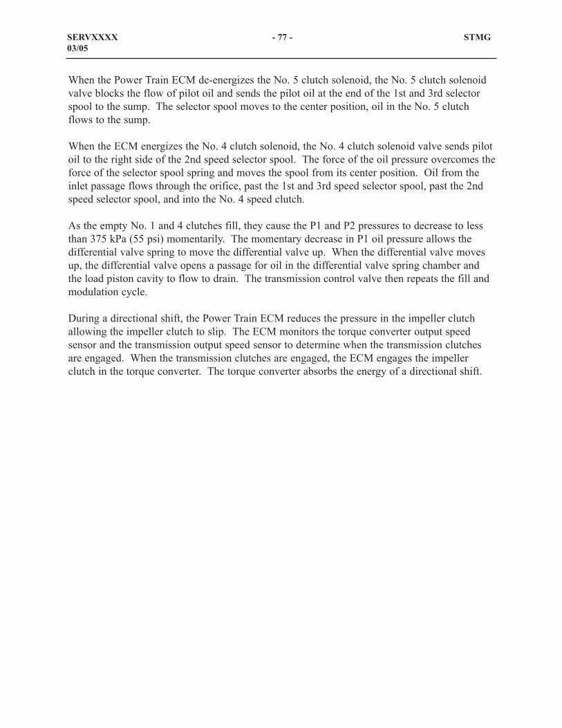
When the Power Train ECM de-energizes the No. 5 clutch solenoid, the No. 5 clutch solenoidvalve blocks the flow of pilot oil and sends the pilot oil at the end of the 1st and 3rd selectorspool to the sump. The selector spool moves to the center position, oil in the No. 5 clutchflows to the sump.
When the ECM energizes the No. 4 clutch solenoid, the No. 4 clutch solenoid valve sends pilotoil to the right side of the 2nd speed selector spool. The force of the oil pressure overcomes theforce of the selector spool spring and moves the spool from its center position. Oil from theinlet passage flows through the orifice, past the 1st and 3rd speed selector spool, past the 2ndspeed selector spool, and into the No. 4 speed clutch.
As the empty No. 1 and 4 clutches fill, they cause the P1 and P2 pressures to decrease to lessthan 375 kPa (55 psi) momentarily. The momentary decrease in P1 oil pressure allows thedifferential valve spring to move the differential valve up. When the differential valve movesup, the differential valve opens a passage for oil in the differential valve spring chamber andthe load piston cavity to flow to drain. The transmission control valve then repeats the fill andmodulation cycle.
During a directional shift, the Power Train ECM reduces the pressure in the impeller clutchallowing the impeller clutch to slip. The ECM monitors the torque converter output speedsensor and the transmission output speed sensor to determine when the transmission clutchesare engaged. When the transmission clutches are engaged, the ECM engages the impellerclutch in the torque converter. The torque converter absorbs the energy of a directional shift.
SERVXXXX - 77 - STMG03/05
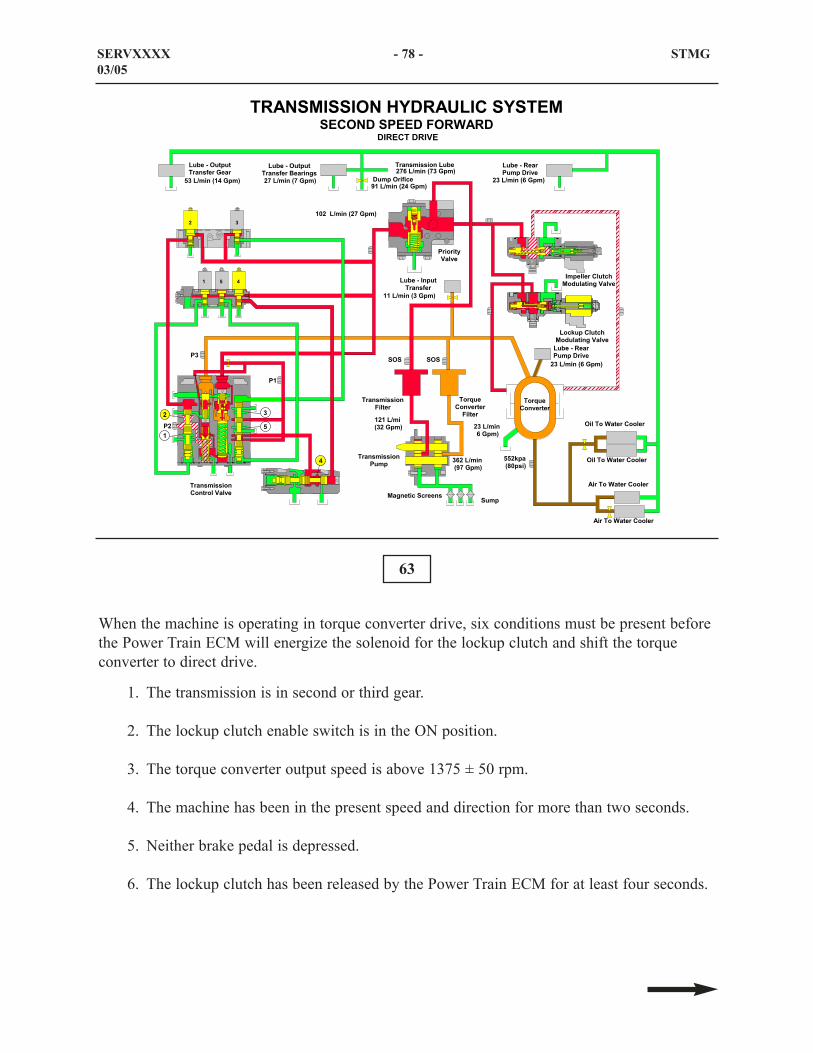
63
When the machine is operating in torque converter drive, six conditions must be present beforethe Power Train ECM will energize the solenoid for the lockup clutch and shift the torqueconverter to direct drive.
1. The transmission is in second or third gear.
2. The lockup clutch enable switch is in the ON position.
3. The torque converter output speed is above 1375 ± 50 rpm.
4. The machine has been in the present speed and direction for more than two seconds.
5. Neither brake pedal is depressed.
6. The lockup clutch has been released by the Power Train ECM for at least four seconds.
SERVXXXX - 78 - STMG03/05
���$� "�� �� �
.�9 �?�# ����������� �
��������������
����
�������������� �
���$� "�� �� ����� �
�������'1���
��� �� ��"���% /�&�������1���
.�%!���"���% /�&�������1���
�#(0�/�����0��>�#(3.�"��>��/�"�0��������#-(#�
���#"���#�1
�������-�� ��"��� �
�������-�� ��"��� �
(������-�� ��"��� �
(������-�� ��"��� �
.�9 �?�# ����������� �
�����������.�9
����������%
.�9 �?������������ ��� ������
.�9 �?������������ ��� ���
/�� ��%��%� �
;��.8���<�����=
;A�.8���<A����=
;A��.8���<A�����=
+��.8���<;,����=;��.8���<�����=���.8���<�,����=
�;��.8���<�;����=
��;!���<CB���=
��;�.8���<+A����=
�B;��.8���<;A����=
.�9 �?���������� �
���.8���<�����=
��� ���
�;
�
; �
� � ,
,
����������"������1���
�;
��
��
;��.8��������=�

When the solenoid for the lockup is energized, the lockup clutch modulating valve opens. Thetransmission pump oil flows past the lockup clutch modulating valve and fills the lockupclutch. The lockup clutch engages and connects the turbine to the rotating housing.
In DIRECT DRIVE, both the impeller clutch and the lockup clutch are engaged. The torqueconverter rotating housing, the impeller, and the turbine turn as a unit. When the solenoid forthe lockup is energized, the lockup clutch modulating valve opens. The transmission pump oilflows past the lockup clutch modulating valve and fills the lockup clutch. The lockup clutchengages and connects the turbine to the rotating housing.
SERVxxxx - 79 - STMG03/05

The 994F Wheel Loader is equipped with two oil-to-coolant coolers (1) and two oil-to-aircoolers (2 and 3). The oil-to-coolant coolers are located on the left side of the engine. Thesetwo coolers use engine coolant to cool the transmission oil as the oil passes through the coolers.In line with the transmission oil flow through the two oil-to-coolant, an orifice is installed todivide the flow of oil between the oil-to-coolant and two oil-to-air coolers. Approximately twothirds of the torque converter outlet oil flow through the oil-to-coolant coolers.
The two oil-to-air coolers are located in the cooler package at the rear of the machine. Cooler(3) has an orifice (not shown) that divides the other one-third of the transmission oil in half.One half of the oil flows through cooler (2) and one half of the torque converter oil flowsthrough cooler (3). The oil from the coolers flow back to the transmission and lubricate thetransmission bearings before returning to the transmission sump.
64
65
SERVXXXX - 80 - STMG03/05
1
2 3
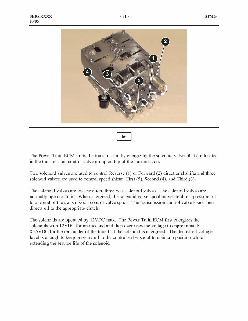
The Power Train ECM shifts the transmission by energizing the solenoid valves that are locatedin the transmission control valve group on top of the transmission.
Two solenoid valves are used to control Reverse (1) or Forward (2) directional shifts and threesolenoid valves are used to control speed shifts: First (5), Second (4), and Third (3).
The solenoid valves are two-position, three-way solenoid valves. The solenoid valves arenormally open to drain. When energized, the solenoid valve spool moves to direct pressure oilto one end of the transmission control valve spool. The transmission control valve spool thendirects oil to the appropriate clutch.
The solenoids are operated by 12VDC max. The Power Train ECM first energizes thesolenoids with 12VDC for one second and then decreases the voltage to approximately8.25VDC for the remainder of the time that the solenoid is energized. The decreased voltagelevel is enough to keep pressure oil to the control valve spool to maintain position whileextending the service life of the solenoid.
66
SERVXXXX - 81 - STMG03/05
1
2
34
5
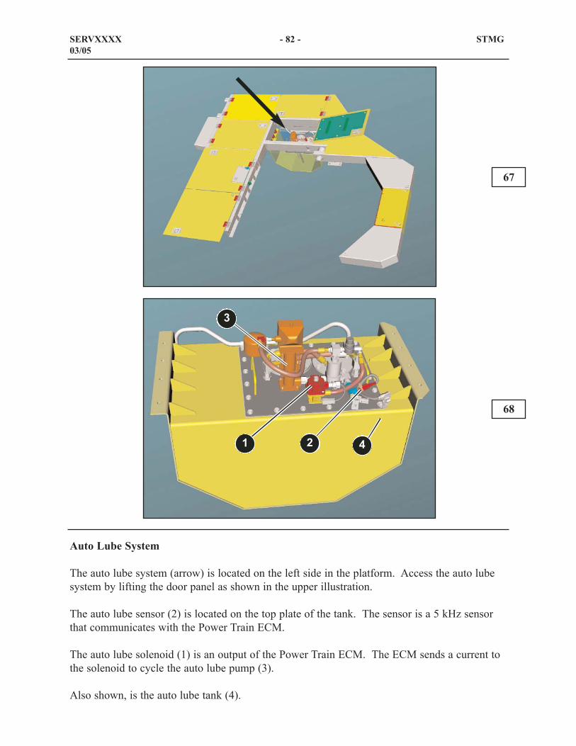
Auto Lube System
The auto lube system (arrow) is located on the left side in the platform. Access the auto lubesystem by lifting the door panel as shown in the upper illustration.
The auto lube sensor (2) is located on the top plate of the tank. The sensor is a 5 kHz sensorthat communicates with the Power Train ECM.
The auto lube solenoid (1) is an output of the Power Train ECM. The ECM sends a current tothe solenoid to cycle the auto lube pump (3).
Also shown, is the auto lube tank (4).
67
68
SERVXXXX - 82 - STMG03/05
1 2
3
4

69
This illustration shows the lubrication points on the rear frame (EEF) of the machine. The autolube pump and tank assembly (1) is located on the left side of the machine in the platform. Theprevious illustration shows the components of the auto lube pump. Also shown is the enginefan system and pulley (2).
The following is a list of the lube points on the EEF.
- Fan drive shaft bearing
- Pulley (support group alternator)
- Rear trunnion (rear axle) (Qty 2)
- Front trunnion (rear axle) (Qty 2)
- Head end of the steering cylinders (Qty 2)
- Lower bearing articulation hitch
Hose (3) supplies auto lubrication to the components on the loader frame (NEEF).
Note: The upper drive shaft bearing is not an auto lube point. This point is greased manuallyby the operator.
SERVXXXX - 83 - STMG03/05
1
3
2

70
This illustration shows the locaton of the auto lube points on the pulley shaft and the fan driveshaft.
SERVXXXX - 84 - STMG03/05

71
This illustration shows the lubrication points on the loader frame (NEEF) of the machine. Theloader arms and the draw bar lube points are not shown in this illustration and will be shown inthe following illustration.
The following is a list of the lube points on the EEF.
- Tilt cylinder head end pins (Qty 2)
- Steering cylinder rod end pins (Qty 2)
- Lift cylinder head end pins (Qty 2)
- Upper bearing articulation hitch
Divider block (1) supplies auto lubrication to the left side of the lift linkage and divider block(2) supplies auto lubrication to the right side of the lift linkage.
Note: The lower drive shaft bearing is not an auto lube point. This point is greased manuallyby the operator.
SERVXXXX - 85 - STMG03/05
12
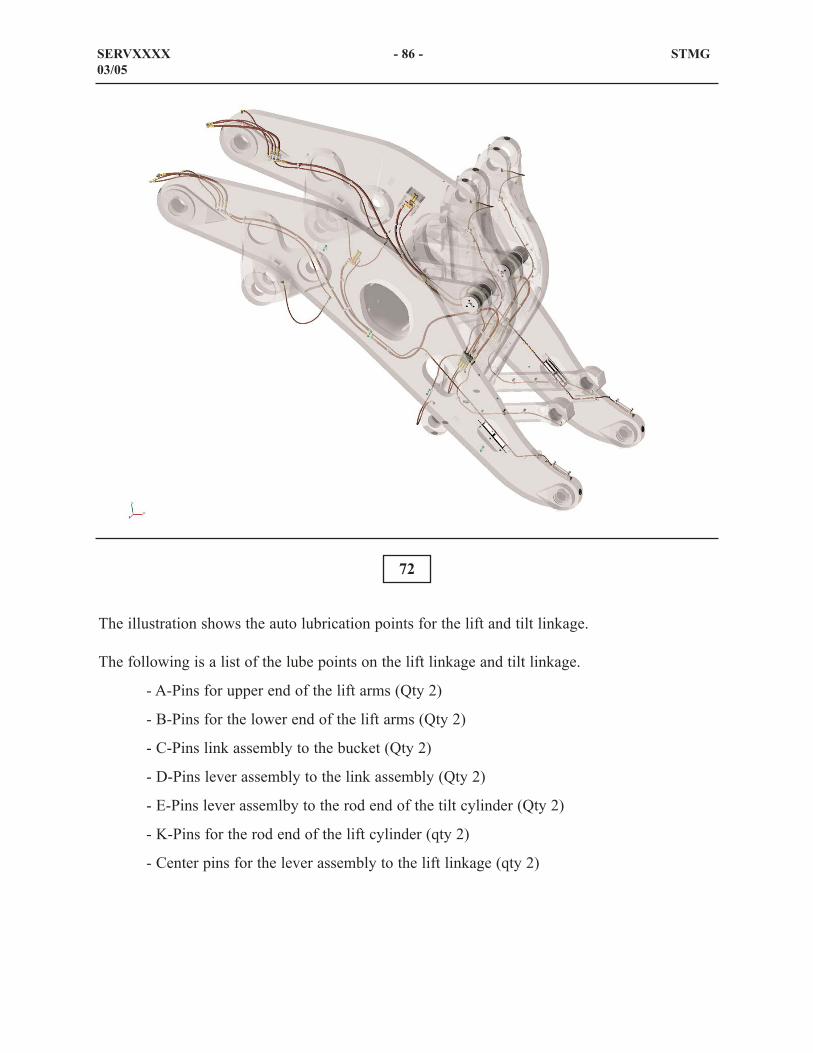
72
The illustration shows the auto lubrication points for the lift and tilt linkage.
The following is a list of the lube points on the lift linkage and tilt linkage.
- A-Pins for upper end of the lift arms (Qty 2)
- B-Pins for the lower end of the lift arms (Qty 2)
- C-Pins link assembly to the bucket (Qty 2)
- D-Pins lever assembly to the link assembly (Qty 2)
- E-Pins lever assemlby to the rod end of the tilt cylinder (Qty 2)
- K-Pins for the rod end of the lift cylinder (qty 2)
- Center pins for the lever assembly to the lift linkage (qty 2)
SERVXXXX - 86 - STMG03/05

The power train hydraulic system is equipped with remote pressure taps. The remote pressuretaps are located in the service bay, behind the cab. The remote pressure taps are:
Rear brake pressure (1)Front brake pressure (2)Brake cooling pump pressure (3)Front brake accumulator pressure (4)Rear brake accumulator pressure (5)Implement pilot pressure (6)Implement cooling pump pressure (7)Left steering pump pressure (8)Right steering pump pressure (9)Steering cooling pump pressure (10)Speed clutch pressure (11)Directional clutch pressure (12)Torque converter inlet pressure (13)Torque converter outlet pressure (14)Transmission lube pressure (15)Impeller clutch control pressure (16)Lock-up clutch control pressure (17)Transmission fluid sampling port (SOS) (18)
73
SERVXXXX - 87 - STMG03/05
1 23 4
5 6
7
8
9
10
11 12 13
14
17
1615
18

74
Implement Hydraulic System
The 994F Wheel Loader implement hydraulic system consists of two basic systems with anadditional common cooling system.
The systems are divided in the following color codes:
Orange Pilot hydraulic system
Red Main hydraulic system
Green Common cooling system for the Implement hydraulic oil
SERVXXXX - 88 - STMG03/05
���� � �������
/����'�� � "�������'�� ��������'�� �
����������
/���# �� ��1��� �
/���"������1��� �
������# �� ��1���
���������� �
������"������1��� ���� � ������"����������
���� � ���'&�����%���!
���� � ��"������������� �
���� � �����"��� �
.���"'��& ��
�����"'��& ��
���� � �������"�� ���������� ��
��� ��� ���� �����%� �
++,���-�.�.�(�#�/�./0���>�#(3.�"��>��/
��������������

75
Implement Electronic Control System
This diagram of the Implement Electronic Control System shows the components whichprovide input signals to the Implement ECM and output signals from the Implement ECM.
The Implement Electronic Control Module (ECM) receives input signals from the varioussensors and switches on the machine. The Implement ECM processes the input signals, makesdecisions, and provides a corresponding signal voltages to the proportional solenoid valves anddetent coils. The Implement ECM stores information from the calibrations, machine settingsand operational functions. The Implement ECM monitors diagnostic conditions and reportsevents to the Cat Monitoring System or to Cat Electronic Technician. Also, the ImplementECM provides a means of calibrating the mechanical components for optimal operation.
The Implement ECM shares operational data with the other ECMs and the Cat MonitoringSystem through the Cat data link.
SERVXXXX - 89 - STMG03/05
������ � ��"���
#��� �� � ��"���
.�* ��� � ��"���
7�%!����� ���*��%
.����.�!��
��������� ��� �1����9� ��������� ��&�1���
.�* ��7�%!����"�� ������ ��&�
"��������.�!
���� � ��� %����%
"������/�&�� �<"/=�
�/�./0��."�#�0�""�0�#�.��>��/
�����"���� �� �������"���� ��
�����7�%!�����*��%
���� � ������
�� ���� �� ���
#��� ��������� ��&��

The input components to the Implement ECM are:
Lift linkage Position Sensor: Sends a PWM signal to the Implement ECM communicatingthe position of the lift linkage in relation to the loader frame.
Kickout set switch: Sends the raise and lower kickout position to the Implement ECM
Tilt kickout switch: Sends a signal to the Implement ECM to de-energize the tilt detent coil atthe exact set position.
Implement pump pressure sensor: Sends the implement pump pressure to the ImplementECM as a pulse width modulated signal.
The output components which receive signals from the Power Train ECM are:
Variable Pump Solenoid Valve: This solenoid valve is an output from the Implement ECMthat controls the signal flow from the implement pump. The solenoid valve controls theupstroke and destroke of the variable piston pump
Lower kickout cushion solenoid: This proportional solenoid valve is an output from theImplement ECM. The lower solenoid directs pilot oil through an orfice to the lower end of thelift stems.
Raise stop solenoid: This proportional solenoid valve is an output from the Implement ECM.Blocks pilot oil flow to the raise end of the lift stems.
Raise kickout detent coil: The coil is an electromagnetic component that retains the liftcontrol lever in the full raise position.
Lower kickout detent coil: The coil is an electromagnetic component that retains the liftcontrol lever in the full lower position.
Tilt kickout detent coil: The coil is an electromagnetic component that retains the tilt controllever in the full tilt back position.
SERVxxx - 90 - STMG03/05

The upper illustration shows the lift linkage position sensor (1). Lift linkage position sensor islocated on the right side of the loader frame. The sensor sends a PWM signal to theImplement ECM reflecting the position of the lift linkage.
NOTE: To calibrate the lift linkage position sensor, refer to the Service Manual module"994F Wheel Loader Hydraulic System, Troubleshooting, Testing and Adjusting PositionSensor (Lift Linkage - (Calibrate)" (Form RENR6323).
The lower illustration shows the tilt kickout switch (2). The tilt kickout switch is located on theright side tilt cylinder. The switch sends a signal to the Implement ECM to de-energize the tiltdetent coil (not shown) as the magnet (3) passes under the switch. Normally, the magnet isadjusted to position the bucket at the proper dig angle.
76
77
SERVXXXX - 91 - STMG03/05
1
2
3

The upper illustration shows the implement pump pressure sensor (1). The pressure sensor islocated on the right side inside the loader frame. Access the pressure sensor from under thefront frame. The sensor sends the pressure through a PWM signal to the Implement ECM.
The lower illustration shows the raise/lower kickout set switch (2) on the panel inside the cab.The switch sends the Implement ECM the position to set the kickout for the raise position andthe lower cushion
78
79
SERVXXXX - 92 - STMG03/05
2
1

The above illustration shows the location of the variable pump solenoid valve (1) in the NEEF(2).
The lower illustration shows the variable pump solenoid valve (1). The valve controls thesignal pressure for the variable displacement piston pump (center section). When the solenoidis de-energized , the valve is closed and the pressure in the signal line instructs the pump to goto maximum flow. When the conditions are met to activate Dig Trigger, the Implement ECMsends current to the solenoid valve. The solenoid is energized and the solenoid valve shifts tothe OPEN position. The signal oil goes tank pressure and the variable pump will be instructedto go to standby.
Also shown are the check valve (3) and the selector and pressure control valve (4)
80
81
SERVXXXX - 93 - STMG03/05
1
3
2
4
1

The upper illustration shows the location of the raise stop solenoid valve and the lower kickoutcushion solenoid valve (1) in releation to the transmission control valve (2).
The lower kickout cushion solenoid valve (3) controls the flow of pilot oil from the pilotcontrol valve to the main control valves. When the solenoid is de-energized, the pilot oil freeflows through the valve. When the solenoid is energized by a signal from the Implement ECM,the flow of pilot oil through the valve is blocked. The pilot oil flows around the solenoid valvethrough orifice (5). The orifice will cause a drop in pilot pressure to the lower end of the liftstem. The lift stems in the main control valves (not shown) will decrease the flow of supply oilto the rod end of the lift cylinder.
82
83
SERVXXXX - 94 - STMG03/05
12
3 4
5

When the lift cylinders approach the raise stop at approximately 20 mm ( 0.8 inch) away fromfull extension, the Implement ECM sends a voltage signal to the raise stop solenoid valve toblock pilot oil to the raise end of the lift stem. The lift stem will shift to the CENTER positionblock supply oil to the head end of the lift cylinders.
SERVXXXX - 95 - STMG03/05

84
The above illustration shows the location of the pumps on the 994F front pump drive.
The implement system has three fixed displacement piston pumps (1) and one variabledisplacement piston pump (2).
The implement oil cooling pump (3), the implement pilot pump (4), and the front pump drivelubrication pump (5) are fixed displacement gear pumps.
SERVxxxx - 96 - STMG03/05
������
/�% � � ��
�
,
�
++,���������������
�����) &�������% � ��������������<���� � �=;��1����9� �������% � �������������<���� � �=������� � ������"����������,������ � ��������������������������������� �.�9��%���������
;

Front Pump Drive Lubrication System
The front pump drive system is located in the loader frame (NEEF). The front pump drivelubrication system lubricates the bearings and gears and filters the oil in the front pump drive.Access the front pump drive (1) from the articulation hitch area.
85
SERVxxxx - 97 - STMG03/05
1

Front Pump Drive System
The oil is drawn from the front pump drive (1) by the front drive lubrication pump (4) and issent through the filter (3). The oil from the filter is sent to the divider block (2) and the oil isdirected to the individual bearing and gear lubrication points in the front pump drive.
The oil filter group consists of the filter base and filter, the SOS fluid sampling port (7), filterbypass switch (5), and the temperature sensor (6). The front pump drive oil filter bypass switchand the front pump drive oil temperature sensor communicate with the VIMS module.
86
87
SERVXXXX - 98 - STMG03/05
1 2
3
4
5
6
7
3

88
Pilot System
This illustration shows a block diagram of the pilot hydraulic system. In this illustration, theengine is running and the control levers are in the HOLD position.
The pilot system is a closed center design. Oil is drawn from the implement hydraulic tank bythe pilot pump. Pump oil is directed through the pilot filter group and is divided into twodirections. One pathe flows to the the pilot relief valve and the other path flows to the selectorvalves . The pilot hydraulic system will constantly operate at the relief valve setting. When thepilot pump pressure reaches the relief valve setting, the relief valve opens. Oil over the reliefvalve flows to the implement oil cooler (not shown) before returning to the hydraulic tank.
The pilot oil flows over an opened check valve 2 to the pilot control valves. Check valve 2blocks oil from returning back to the pump. The pilot oil will be blocked at the pilot controlvalves until either the tilt or lift control lever is moved. Check valve 1 is installed between thepilot line and the selector and pressure control valve in order to block the pilot oil from flowingto the selector and pressure control valve.
Pilot oil from the filter is also directed to the selector valves for the lift and tilt pilot lines.When the control levers are in the HOLD position, the pressure at each end of the selectorvalves is equal.
SERVxxxx - 99 - STMG03/05
���.���
"�����
1��� �
�������
"�����
1��� �
������# �� �
1���
�����
���� �
�����
����
" %!
1��� ��
" %!
1��� �;
� � %���
(&
�� ����
"�����
1���
���� � �
�'&�����%���!
�� � %����1��� �
�++,���/�./0�
��.����>�#(3.�"��>��/
��.������
1��� .�* �
7�%!���
"�� ��
��� ��&
1���
� $� %
1���
.���
����
��� ��&
1���
.���
����
.����"'��& ��
����
��
���� � �
"��� �
�����/�! ���(&�1 ��1���

The selector valves will be in the CENTER position. Pilot oil flows through the selector valvesand through the orifices. The selector valve is used in order to circulate a small amount ofwarm pilot oil from the pilot pump into the pilot lines when the pilot control valve controlsaren't being used to help out with cold weather conditions. As soon as the operator moveseither control lever, in either direction, the valve shifts and blocks the flow to the pilot lines. It'scalled a thermal purge because it "purges" warm pilot oil into the pilot system. In the HOLDposition, the pilot oil flows back through the tank port on the pilot control valve to thehydraulic tank.
The selector and pressure control valve is used in the pilot system to control the pilot pressurethat is provided when the lift cylinders are extended and there is pressure in the head end of thelift cylinders. The selector valve blocks the flow of oil through the selector valve when thepilot oil pressure provided by the pilot pump is greater than the pressure at the output end ofthe selector valve. In the event that the engine is not running and the lift cylinders areextended, the oil at the output of the selector valve will be greater than the pilot oil and checkvalve 1 will unseat. The oil from the head end of the lift cylinders flows through the selectorvalve, over the check valve 1, and flow to the pilot control valve. The pilot system will havesufficient pilot oil to lower the lift linkage.
SERVXXXX - 100 - STMG03/05

89
In the event the engine is not running and the bucket is raised and must be lowered, the pilotsystem will use oil pressure in the head end of the lift cylinders for the necessary pilot pressure.Oil in the head end of the lift cylinders (blue) flows to the selector and pressure control valve.The pilot oil will open check valve 1 and flow the the pilot control valves. Pilot oil will flow tocheck valve 2 and be blocked.
When the oil pressure in the head end of the lift cylinders goes above the adjusted pressure ofthe selector valve, the valve will shift and the excess oil pressure will be directed to tank. Theselector and pressure control valve reduces the pressure and makes the low pressure oilavailable for emergency use in the pilot system.
When the lift control lever is moved in the lower direction, the reduced pilot oil will flow fromthe lift control valve through the lower kickout cushion solenoid valve to the lower ends of thelift stems (not shown) in the main control valve.
SERVXXXX - 101 - STMG03/05
���.���
"�����
1��� �
�������
"�����
1��� �
������# �� �
1���
�����
���� �
�����
����
" %!
1��� ��
" %!
1��� �;
� � %���
(&
�� ����
"�����
1���
���� � �
�'&�����%���!
�� � %����1��� �
�++,���/�./0�
��.����>�#(3.�"��>��/
0��0�0���#300�0�
.���
�����
1��� .�* �
7�%!���
"�� ��
��� ��&
1���
� $� %
1���
.���
����
��� ��&
1���
����
.����"'��& ��
����
��
���� � �
"��� �
������/�! ���(&�1 ��1���

The implement hydraulic system is made up of the following components. The illustrationshows the location of the components in the NEEF
Pilot Filter Group (1)Non-Engine-End-Frame (2)Pilot pump (gear) (3)Selector and pressure reducing valve (4)Float sequence valve (5)Pilot relief valve (6)Selector valve (thermal bypass) (7)Selector valve (thermal bypass) (8)
90
SERVXXXX - 102 - STMG03/05
12
3
4 5
6
7 8

The upper illustration shows the pilot filter group that is located in the NEEF (1). The pilotfilter group is equipped with a filter (3) that is rated at 33 micron and a pressure switch (2).The pressure switch communicates with the VIMS module relaying that the pilot oil is belowthe required pressure.
The lower illustration shows the location of the pilot components the Selector and pressurecontrol valve (6), check valve (7), check valve (8), float sequence valve (9), pilot relief valve(10), and selector valves (thermal purge) (11 and 12).
Also shown are the implement hydraulic tank (4) and the variable pump solenoid valve (5)
91
92
SERVXXXX - 103 - STMG03/05
1
2
567
3
8
9
4
11 1210

Pilot Control Valve
The pilot control is located in the cab to the right of the operator's seat. The control consists ofthe tilt control lever (2), the lift control lever (3) and the implement lever lock (1). When theimplement lever lock is in the forward position, the control levers are unlocked. When thelever lock is pulled back, the control levers are locked.
The pilot control valve is also equipped with detent coils (not shown). The detent coils willhold the lift control lever in full RAISE and full LOWER and the tilt control lever in the fullTILT BACK positions until the linkage has reached the set kickout position.
93
SERVXXXX - 104 - STMG03/05
1
23

94
Tilt Pilot Control Valve
This illustration shows a sectional view of the tilt pilot control valve in the HOLD position.When the engine is running and the control lever is in the HOLD position, pilot oil from thepilot pump enters the pilot control valve and is blocked by the dump and tilt back meteringstems. At the same time, a path for any pilot oil in the system to flow back to the hydraulictank through pilot control valve. The lift pilot control valve operates the same way as the tiltpilot control valve.
The tilt pilot control valve is equipped with a detent coil for the tilt back function only. Whenthe tilt control lever is pulled to the full travel, the retainer will engage the detent coil. Thedetent coil will hold the retainer until the current to the detent coil is interupted. The lift pilotcontrol valve is equipped with a detent coil for both raise and lower functions as shown in thenext illustration.
SERVXXXX - 105 - STMG03/05
3�� ������ ��<����=
3�� ��" � ���������
.�* ������ �
# ��� �
/ � ���������
�������%!�/ � ������ �
# ��� �
3�� ��" � ���������
.�* ������ �
# ��� �
.�* ��" � ���������
/ � ������ �������
�����/ � ������ �
# ��� �
����������
� � ��"�����
/ � ������ �������
3�� ������ ��<�������%!=
���/���"������1���
���������������
����'&�����%���!
��.����.���"�0�#�.�1(.1��.�

95
Lift Pilot Control Valve
This illustration shows a sectional view of the lift pilot control valve in the RAISE position. Inthe RAISE position, the pilot oil (orange) from the pilot pump enters the control valve. Whenthe When the operator moves the lift control lever into the raise direction, the pivot plate isrotated and the upper plunger, the upper retainer, lower plunger, metering spring, the lowerretainer and the metering stem moves downward. As the metering stem moves downward, theport holes in the stem pass over the oil passage from the pilot pump. Pilot oil flows from thepassage through the center of the metering stem to the end of the lift stem in the main controlvalve (not shown). At the same time, the metering stem spring is adding an upward forceagainst the upper edge of the metering stem. Return oil from the main control valve throug thelowermetering stem, the center of the metering stem and to the tank port.
The objective of the metering stem is to allow movement of the stem in the main control valveproportionally with the movement of the pilot control lever. The metering stem and themetering spring function as a pressure reducing valve and control the pilot oil pressure at theend of the main control valve stem.
As the metering stem moves downward, pilot oil flows through the orifice, the center of themetering stem and out to the main control valve.
SERVxxxx - 106 - STMG03/05
���/��
"������1���
���������������
����'&�����%���!
.������.���"�0�#�.�1(.1#(��
#��� �/ � ������ �
.�* �8�����
�/ � ������ �
� � ��"����<#��� =
�����/��
"������1���
� � ��"����<�����=
/ � ������ �������
/ � ���������
" � ��# ��� �
.�* ������ �
3�� ��" � ���������
3�� ������ ��
3�� ��# ��� ��
���������� �
.�* ��# ��� �

The flow of pilot oil is blocked at the main control valve stem causing the pilot pressure toincrease. The pressure increase overcomes the centering spring for the main control valve stemand shifts the stem. Then, supply oil is directed to the actuator.
The pressure increase is also sensed against the lower end of the metering stem. When thepressure increase overcomes the applied force, the metering stem moves up and compresses themetering spring. The upward movement restricts the flow of pilot through the orifice in themetering stem. Restricting the pilot oil flow controls the signal pressure at the stem of themain control valve . The metering spring therefore adjusts the pressure at the main controlvalve stem in proprtion to the movement of the pilot control lever.
When the lift control lever is moved to full travel and the detent coil is energized, the upperretainer (raise) will be held in position by electromagnetic force of the detent coil. The detentcoil will be energized until the position sensor (not shown) recognizes the kickout position.The lever can be removed from a detent position manually.
When the operator moves the lift control lever to the full LOWER position, the lower side ofthe pilot control valve will operated similiar to the raise side and the float detent coil will holdthe control valve in the FLOAT position.
SERVXXXX - 107 - STMG03/05

96
Implement Hydraulic System
The implement hydraulic system is equipped with three fixed displacement piston pumps andone variable displacement piston pump. The three fixed displacement pumps draw oil from theimplement hydraulic tank. The supply oil is directed through the high pressure screens and theindividual relief valves. The individual relief valves limits the supply oil pressure that isflowing to the left and right control valves. This illustration shows the main control valve withno signal pressure from the pilot control valve (not shown). The oil that is between the maincontrol valve and both ends of the lift and tilt cylinders is blocked.
Each individual piston pump is equipped with its own case drain filter.
Oil flow from the three fixed displacement pumps operate the lift and tilt cylinders. Oil flow ismetered to the cylinders by the main control valve stems. The oil flow around the stems iscontrolled by the movement of the stems in the valve through the pressure that is applied to theends of the stems. The operator controls the pilot oil flow and pressure that shifts the stems.Also, movement of the valve stems opens a passage for the oil in the opposite end of thecylinders to return to tank.
SERVXXXX - 108 - STMG03/05
���.���
"�����
1��� �
�������
"�����
1��� �
������# �� �
1���
�����
���� �
�����
����
" %!
1��� ��
" %!
1��� �;
� � %���
(&
�� ����
"�����
1���
���� � �
�'&�����%���!
�� � %����1��� �
�++,���/�./0�
��.����>�#(3.�"��>��/
��.������
1��� .�* �
7�%!���
"�� ��
��� ��&
1���
� $� %
1���
.���
����
��� ��&
1���
.���
����
.����"'��& ��
����
��
���� � �
"��� �
�����/�! ���(&�1 ��1���

97
Implement Hydraulic System
In the illustration, the graphic shows the machine in dig trigger mode. The machine is in firstspeed forward, the ground speed is less than 6.8 kmh (4.25 mph), and the B-Pin is above thehorizontal line of the A-Pin.
The three fixed displacement piston pumps and one variable displacement piston pump aresupplying the oil flow to the implement hydraulic system. The four pumps draw oil from theimplement hydraulic tank. The supply oil is directed through the high pressure screens and theindividual relief valves. The individual relief valves limits the supply oil pressure that isflowing to the left and right control valves. This illustration shows the main control valve witha raise signal from the pilot control valve (not shown).
Also, each individual piston pump is equipped with its own case drain filter.
An increased oil flow will be directed to the head end of the lift cylinders until the lift stopsolenoid valve is energized and pilot oil to the end of the lift stem in the main control valve isblocked or the operator releases the lift control lever.
SERVXXXX - 109 - STMG03/05
���� � �
�'&�����%���!
. ��
"������1���
. ��
���� � �
����
#�� �
���� � �
����
��&��
���� � �
����
# �� �
1���
# �� �
1���
++,�
�/�./0�
�>�#(3.�"��>��/
# �� �
1���
#�� �
"������1���
# �� �
1���
���
�� ���� ��%�
��� ��� ����
��%� �
���
�� ����
�%� �
1(#�(�.�����.("/0�
�����0���3/��3���#�7�

98
The implement hydraulic system is built into the Non-Engine-end-Frame (1). The followingcomponents are shown in the NEEF: case drain filters and bypass switches (2), the implementpumps and pump drive (3), the high pressure screen groups and relief valves (5, 6, 7, 9), andthe hydraulic tank (4). High pressure screen (7) filters supply oil for the left side fixeddisplacement pump. High pressure screen (9) filters supply oil for the right side fixed pistonpump. High pressure screen (5) filters supply oil for the variable displacement pump (sectionof the tandem pump). High pressure screen (6) filters supply oil for the center fixeddisplacement pump (section of the tandem pump).
The main control valve is made up of two valve sections. The right control valve (8) and theleft control valve (10).
SERVXXXX - 110 - STMG03/05
1
2
3
4
5 67
8910

The implement hydraulic system is equipped with four case drain filters with bypass switches.These filter groups filter the case drain oil from the four implement pumps. The followingfilter and bypass switch are in line with the following pump.
Filter (2) and bypass switch (1) are in line with the left side fixed displacment pump.
Filter (4) and bypass switch (3) are in line with the center fixed displacment pump.
Filter (6) and bypass switch (5) are in line with the variable displacment pump.
Filter (8) and bypass switch (7) are in line with the right side fixed displacment pump.
99
SERVxxxx - 111 - STMG03/05
1
2
3
4
5
6
7
8

High pressure screen (2) is a 200 micron filter that is between the implement pump and therelief valve group (3). Each individual implement pump is equipped with it own high pressurescreen and relief valve. The relief valve pressure is adjusted by rotating the adjustment screw(1). The factory pressure setting for the relief valves is approximately 32800 kPa (4760 psi).
The relief valve is also equipped with a check valve (not shown) with free flow out of thevalve.
100
SERVxxxx - 112 - STMG03/05
1
2
3

This illustration shows the front pump drive (2) and implement pumps removed from the Non-Engine-Engine Frame. The right fixed pump (1) and left fixed pump (3) are installed on eachside of the tandem pump (4). The tandem pump is a combination of a fixed piston pump(nearest to the pump drive) and a variable displacement piston pump. The variabledisplacement piston pump is equipped with a pump control valve (5) that controls theupstroking and de-stroking of the pump when the machine requirements are met.
101
102
SERVxxxx - 113 - STMG03/05
1 2 3
4
5 4

103
The 994F Wheel Loader is now equipped with a new center pump on the front pump drive.The new pump is a two section piston type pump. The tandem pump is equipped with animpeller pump (charge) that draws oil from the implement hydraulic tank (not shown) anddirects oil to the inlet cavities of each pump section.
The pump section that is located next to the pump drive is a fixed displacement piston pump.This section will continuously supply oil to the main control valve when the engine is running.The displacement for the fixed pump is predetermined by the locking bolts that retain theswashplate at the fixed angle.
The other pump section is a variable displacement piston pump. This section will supply eitherminimum flow or maximum flow to the main control valve depending on the signal pressure atthe pump control valve. The pump control valve will control the output of the variable pumpusing pump pressure to shift either the flow control spool (not shown) and the pressurecompensator spool (not shown). In this illustration showing minimum flow, oil pressure isdirected to the large piston and the force against the piston moves the piston rod and theswashplate against the stop. At the same time, the spring and the pressure that is behind thesmall piston will be overridden. Small piston will allow the swashplate to rotate against thestop. The pump will supply sufficient oil pressure to lubricate the pump and supplyinstantaneous response to a request for maximum flow.
SERVXXXX - 114 - STMG03/05
��) &�������% � ������������
������� �
�/�./0���3/���(0��>
�����"������1���
�����������
����������
������� �
.�%!�����
1����9� �������% � ������������
�*�� ����
.��� (%�����������
��� �� �����
��������� ���������� �
�*�� ���� .�%!�����
.�%!�����

104
The signal for the control of the upstroke and destroke of the variable displacement pistonpump is through a voltage signal from the Implement ECM to the solenoid valve (not shown)for variable displacement piston pump. The solenoid valve relieves or retains the oil pressurein the signal line to the pump control valve. In this illustration, the signal oil pressure isreleived to tank pressure.
When the oil at the signal line goes to tank pressure, oil pressure at the right end of the flowcompensator spool decreases. The spring force on the right side of the flow compensator spoolis overridden by the force that is developed by the system pressure on the left side of the spool.The spool shifts to the right. System pressure is allowed to flow over the flow compensatorspool to the large actuator piston. The increased pressure in the large actuator piston overcomesthe combined force of the small actuator and bias spring and moves the swashplate to a reducedangle.
As pump flow decreases, supply pressure also decreases. When the supply pressure decreasesand equals the sum of the oil pressure at the right end of the flow compensator spool and springforce, the flow compensator spool moves to a metering position and the system stabilizes.
SERVXXXX - 115 - STMG03/05
��/��
"�����1���
����� ��&1���
�����) &������% � ������
1(#�(�.��3/��(0���3/��"�0�#�.�1(.1
��(0��>
���*"��� �����
�����
�� ���� "��� �����
�����
������(%�����������
.��� (%�����������
1����9� ������% � �
����
�����"������1���
�����%
�����%
�����%
��� �� ������
����������

105
The fixed displacement pump supplies oil to the main control valve continuously when theengine is running. The displacement for the fixed pump is predetermined by the stops thatretain the swashplate at the fixed angle.
The pump section on the right is a variable displacement piston pump. This section will supplyeither minimum flow or maximum flow to the main control valve depending on the signalpressure at the pump control valve. In this illustration, the pump is showing maximum oilflow. The oil pressure that is behind the large piston is relieved to tank. At the same time, thespring and the pressure that is behind the small piston will override the large piston and thesmall piston will rotate the swashplate against the lock stop. The variable pump will upstroketo maximum flow. The pump will continue to provide maximum flow until the pressure at thesignal pressure at the pump control valve changes.
SERVXXXX - 116 - STMG03/05
��) &�������% � ������������
������� � �����"������1���
�����������
����������
.�%!�����
1����9� �������% � ������������
�*�� ����
.��� (%�����������
��� �� �����
��������� ���������� �
�*�� ���� .�%!�����.�%!�����
������� �
�/�./0���3/�/(5�/3/��.�-

106
The signal for the control of the upstroke and destroke of the variable displacement pistonpump is through a voltage signal from the Implement ECM to the solenoid valve (not shown)for variable displacement piston pump. The solenoid valve relieves or retains the oil pressurein the signal line to the pump control valve. In this illustration, the signal oil pressure isretained at system pressure.
When the oil at the signal line increases to system pressure, oil pressure at the right end of theflow compensator spool is increased. The combination of the spring force and the systempressure on the right side of the flow compensator spool overrides by the force that isdeveloped by the system pressure on the left side of the spool. The flow compensator spoolshifts to the left. Oil at the large actuator piston is allowed to flow over the flow compensatorspool and the pressure compensator spool. The large actuator piston is at tank pressure. Theforce of the bias spring and the system pressure on the small piston enables the small piston tooverride the large piston and the swashplate will move to maximum angle.
The pump will upstroke and add an oil source to the main control valve to increase the cycletime of the raise function and the dump cycle time if the following conditions are met. Themachine is in first speed forward, the ground speed is below 4.25 mph, and the B-Pin is abovethe horizontal line of the A-Pin.
SERVXXXX - 117 - STMG03/05
��/��
"�����1���
����� ��&1���
�����) &������% � ������
1(#�(�.��3/��(0���3/��"�0�#�.�1(.1
/(5�/3/��.�-
���*"��� �����
�����
�� ���� "��� �����
�����
��� �� ������
.��� (%�����������
1����9� ������% � �
����
������(%�����������
�����%
�����%
�����%
�����"������1���

107
This illustration shows the components in the right side implement control valve. The controlvalve is accessed from the articulation hitch. The following is a list of the components.
- Inlet port for the right fixed displacement implement pump (1)- Tilt rod end port (2)- Tilt load check valve(3)- Check valve (4)- Tilt head end port (5)- Check valve (6)- Lift rod end port (7)- Lift head end port (8)- Check valve (9)- Makeup and vent valve (10)- Lift load check valve (11)- Hydraulic tank port (12)
SERVXXXX - 118 - STMG03/05
1
2 3
4 5 6
78
9
1011
12

108
This illustration shows the back side of the right implement control valve. Port (1) is the inletconnection for the center variable displacement piston pump.
SERVXXXX - 119 - STMG03/05
1

109
The 994F Wheel Loader main control valve is made up of two control sections, the rightcontrol section and the left control section. The above illustration shows the right side controlvalve in the float position including the makeup and vent valve. The makeup and vent valve isshown in both the makeup and float operation.
In the makeup operation, the pressure in the hydraulic tank exceeds the pressure in the rod endof the lift cylinder. Lowering the bucket faster than the pump can fill the rod end of the liftcylinder the piston displacement causes a vacuum in the rod end of the lift cylnders. Themakeup valve allows oil from the tank line to flow into the rod end of the lift cylinders and fillthe void.
In the float operation, the makeup and vent valve allows the oil that is holding the vent valveagainst the seat to flow through the float sequence valve (not shown) to the hydraulic tank. Thesmall orifices in the base of the vent valve (in the left control vent valve) restrict oil flow to thchamber that is behind the valve. With the oil flowing from behind the vent valve faster thatnthe oil flowing in, the pressure difference between the oil around the vent valve and the oilbehind the vent valve increases enough to lift the vent valve off its seat. When the vent valvemoves off the seat, the oil from the implemnt pumps flow past the vent valve to the hydraulictank. Both ends of the lift cylinders are open to the hydraulic tank allowing the bucket to floatalong the contour of the ground.
SERVXXXX - 120 - STMG03/05
�����!
�.�(�
����
#�&�&
"'��& �
�������!
/(73�
��
#�&�&
"'��& �
��������
� $� % �1���
#�����"�0�#�.�1(.1#����������0��.�(�
��������
� $� % �1���
������ �&�&
%'��& �
���#�&�&
"'��& �
�����1����9�
������% � �
����
�����#�� ����) &
������% � ������
����'&�����%
��!

In the float operation, the makeup and vent valve allows the oil that is holding the vent valveagainst the seat to flow through the float sequence valve (not shown) to the hydraulic tank. Thepressure of the supply oil that is flowing to the rod end of the lift cylinders acts against the ventvalve and the force overrides the spring and the valve opens. When the vent valve shifts to theOPEN position and the supply oil flows to the hydraulic tank. At that time, both ends of the liftcylinders will be open to the tank. This will allow the bucket to follow the contour of theground.
SERVXXXX - 121 - STMG03/05

110
This illustration shows the components in the left side implement control valve. The controlvalve is accessed from the articulation hitch. The following is a list of the components.
- Inlet port for the left fixed displacement implement pump (1)- Check valve (2)- Lift head end drain port (3)- Tilt load check valve (4)- Relief and makeup valve (5)- Tilt head end port (6)- Tilt rod end port (7)- Relief and makeup valve (8)- Lift rod end port Check valve (9)- Lift head end port (10)- Makeup and vent valve (11)- Relief and makeup valve (12)- Lift load check valve (13)- Hydraulic tank port (14)
SERVXXXX - 122 - STMG03/05
12 3
5 67
8
9 1011
12
13 14
4

111
This illustration shows the back side of the left implement control valve. Port (1) is the inletconnection for the center fixed displacement piston pump.
SERVXXXX - 123 - STMG03/05
1

112
The 994F Wheel Loader main control valve is made up of two control sections, the rightcontrol section and the left control section. The above illustration shows the left side controlvalve in the float position including the makeup and vent valve. The makeup and vent valve isshown in both the makeup and float operation.
In the makeup operation, the pressure in the hydraulic tank side of the vent valve exceeds thepressure in the rod end of the lift cylinder. Lowering the bucket faster than the pump can fillthe rod end of the lift cylinder the piston displacement causes a vacuum in the rod end of thelift cylnders. The vent valve on the left control valve is equipped with an orifice. The makeupvalve allows oil from the tank line to flow into the rod end of the lift cylinders and fill the void.
In the float operation, the makeup and vent valve allows the oil that is holding the vent valveagainst the seat to flow through the float sequence valve (not shown) to the hydraulic tank. Thesmall orifices in the base of the vent valve restrict oil flow to the chamber that is behind thevalve. With the oil flowing from behind the vent valve faster than the oil flowing in, thepressure difference between the oil around the vent valve and the oil behind the vent valveincreases enough to lift the vent valve off its seat. When the vent valve moves off the seat, theoil from the implemnt pumps flow past the vent valve to the hydraulic tank. Both ends of thelift cylinders are open to the hydraulic tank allowing the bucket to float along the contour of theground.
SERVXXXX - 124 - STMG03/05
.���"�0�#�.�1(.1.��������0��.�(�
�����. �� ���) &
�������% � � �����
�����" � ����) &
������% � � �����
������ �&�&
%'��& �
���#�&�&
"'��& �
�����!
�.�(�
����
#�&�&
"'��& �
�������!
/(73�
��
#�&�&
"'��& �
��������
� $� % �1���
��������
� $� % �1���
������ �&�&
�.��� �"'��& ��
(�)�����'��� �
.��� ��� �
/�! ���(&�1 � �1���

113
The left control valve on the 994F Wheel Loader is now equipped with an auxiliary stem thatuses pilot oil pressure from the lower pilot valve to control when the stem will be shifted.When the lower pilot oil reaches reaches the required pressure, the force that is developed bythe pilot oil pressure will override the springs on the right side of the auxiliary stem. Theauxiliary stem will start to shift to the right. Return oil from the head end of the lift cylinderswill be allowed to flow around the auxiliary stem through the passage in the valve to thehydraulic tank. This will increase the lower cycle time by approximately 10%.
SERVXXXX - 125 - STMG03/05
.���"�0�#�.�1(.1.�-#
�����. �� ���) &
�������% � � �����
�����" � ����) &
������% � � �����
������ �&�&
%'��& �
���#�&�&
"'��& �
������ �&�&
�.��� �"'��& ��
(�)�����'��� �

114
Implement Hydraulic System Schematic HOLD
This schematic shows the hydraulic flow with the control levers in the HOLD position.
When the engine is running, pilot oil that flows from the pilot pump through the pilot reliefvalve and is blocked at the pilot control valve. At the same time, oil from the pilot pump flowsthrough the tilt selector valve and lift selector valve. With no signal pressure at either end ofthe selector valves, the selector valves are in the CENTER position. The pilot oil that isflowing out of the selector valves pass through orifices. Then, the oil flows back through thepilot control valves to the hydraulic tank.
The two fixed displacement piston pumps draw oil from the hydraulic tank. The pumps directoil through high pressure screens, over the individual relief valves and supply hydraulic oil tothe main control valve. The open center valve directs the supply oil through the main controlvalve to the hydraulic tank. Also, the tandem pump draws oil from the hydraulic tank. Thefixed displacement pump draws oil from the hydraulic tank and directs supply oil to the maincontrol valve. With the B-Pin below the horizontal level of the A-Pin, the variabledisplacement pump will be at zero flow.
SERVxxxx - 126 - STMG03/05
���������
���� �
�����
����
������# �� �
1���
" %!
1���
" %!
1���
� � %���
(&
��� ����
�"�����
1���
�����
� � %���
1���
������"������1���
.�* �
7�%!���
"�� ��
��� ��&
1���
�����
� $� %
1���
#���
����
��� ��&
1���
.�������
"��
����
���� �
"��
����
���� �
"��
����
���� �
"��
����
���� �
��) &
������% � �
����
��) &
������% � �
����
��) &�(&
1����9�
������% � �
����
��� ��� ����
�%� �
��� ��� ����
�%� �
��� ��� ����
�%� �
��� ��� ����
�%� �
# �� �
1���
# �� �
1���
# �� �
1���
# �� �
1���
�� ����
� ���
1����9�
����
��� ��&
1���
���� � ���'&�����%���!
���� � �
���
. � �
� ���
.�$��&
. � �
���
�������%! �������%!���� ����
#��� .�* � .�* �#���
��
���� � �
���
"��� �
)��������!)��������! )��������!
�� �! ��# �� ��1���
�� �! ��# �� ��1���
.����� �&
&�� ���
.� �# �� ��1���
.�
# �� ��1���
.�
# �� ��1���
.�* �
� $� %
�.���
� � %���
1���
��.�
1(#�(�.������0��3/�����#�7�
++,��-�.�.�(�#��/�./0���>�#(3.�"��>��/
.������ � .������ �
������� � ������� �
/�! ��
(&
1 ��1���
/�! ��
(&
1 ��1���
������%

115
This illustration shows the hydraulic oil flow with the variable displacement piston pumpdestroked.
When the lift control lever is in the RAISE position, pilot oil is directed through lift stopsolenoid valve to the raise ends of the individual lift stems in the main control valve. Also, thepilot oil pressure to the right side of the lift selector valve increases, the lift selector valve shiftsto the left. The flow of pilot oil through the lift selector valve is blocked. All the pilot oil isdirected to the ends of the raise end of the lift stems. The force of the oil pressure on the liftstems cause the spools to move against the centering springs. The lift stems shift to the RAISEposition. At this time, the lift stems direct supply oil flow to the head end of the lift cylinders.
When the lift linkage position sensor communicate that the lift cylinders are at approximately70 mm (2.75 inch) from the end of stroke, the Implement ECM energizes the raise stopsolenoid valve and the flow of pilot oil to the end of the lift stems is blocked. The lift stemswill shift back to the CENTER position. The supply oil to the lift cylinders will be blocked.
SERVxxxx - 127 - STMG03/05
���������
���� �
�����
����
������# �� �
1���
" %!
1���
" %!
1���
� � %���
(&
��� ����
�"�����
1���
�����
� � %���
1���
������"������1���
.�* �
7�%!���
"�� ��
��� ��&
1���
�����
� $� %
1���
#���
����
��� ��&
1���
.�������
"��
����
���� �
"��
����
���� �
"��
����
���� �
"��
����
���� �
��) &
������% � �
����
��) &
������% � �
����
��) &�(&
1����9�
������% � �
����
��� ��� ����
�%� �
��� ��� ����
�%� �
��� ��� ����
�%� �
��� ��� ����
�%� �
# �� �
1���
# �� �
1���
# �� �
1���
# �� �
1���
�� ����
� ���
1����9�
����
��� ��&
1���
���� � ���'&�����%���!
���� � �
���
. � �
� ���
.�$��&
. � �
���
�������%! �������%!���� ����
#��� .�* � .�* �#���
��
���� � �
���
"��� �
)��������!)��������! )��������!
�� �! ��# �� ��1���
�� �! ��# �� ��1���
.����� �&
&�� ���
.� �# �� ��1���
.�
# �� ��1���
.�
# �� ��1���
.�* �
� $� % �
�.���
� � %���
1���
#(��
1(#�(�.������0��3/�����#�7�
++,��-�.�.�(�#��/�./0���>�#(3.�"��>��/
������� � ������� �
.������ � .������ �
/�! ��
(&
1 � �1���
/�! ��
(&
1 � �1���
������%

116
Implement Hydraulic System RAISE
This illustration shows the hydraulic oil flow when the control lever is moved to the RAISEposition and the variable displacement piston pump upstroked.
When the pilot control lever is in the RAISE position, pilot oil is directed through lift stopsolenoid valve to the raise ends of the lift stems. Also, the pilot oil that is flowing to the liftselector increases in pressure, the lift selector valve shifts to the left. The flow of pilot oilthrough the lift selector valve is blocked. All the pilot oil is directed to the raise end of the liftstems. The force of the oil pressure on the lift stems push the lift stems to move against thecentering springs to the RAISE position. The lift stems send supply oil flow to the head end ofthe lift cylinders.
When the lift arms raise to the B-Pin over the horizontal line of the A-Pin, 1st speed forwardfor at least 2.0 seconds, and ground speed is less than 6.8 kilometers/hr (4.25 mph), theimplement ECM sends a signal to energize the variable pump solenoid valve. Pump control oilis relieved to tank. The variable displacement piston pump will upstroke.
When the lift cylinders are at approximately 70 mm (2.75 inch) from the end of stroke, theImplement ECM energizes the raise stop solenoid valve and the flow of pilot oil to the end ofthe lift stems is blocked. The lift stems will shift to the CENTER position. The supply oil tothe head end of the lift cylinders will be blocked.
SERVxxxx - 128 - STMG03/05
���������
���� �
�����
����
������# �� �
1���
" %!
1���
" %!
1���
� � %���
(&
��� ����
�"�����
1���
�����
� � %���
1���
������"������1���
.�* �
7�%!���
"�� ��
��� ��&
1���
�����
� $� %
1���
#���
����
��� ��&
1���
.�������
"��
����
���� �
"��
����
���� �
"��
����
���� �
"��
����
���� �
��) &
������% � �
����
��) &
������% � �
����
��) &�(&
1����9�
������% � �
����
��� ��� ����
�%� �
��� ��� ����
�%� �
��� ��� ����
�%� �
��� ��� ����
�%� �
# �� �
1���
# �� �
1���
# �� �
1���
# �� �
1���
�� ����
� ���
1����9�
����
��� ��&
1���
���� � ���'&�����%���!
���� � �
���
. � �
� ���
.�$��&
. � �
���
�������%! �������%!���� ����
#��� .�* � .�* �#���
��
���� � �
���
"��� �
)��������!)��������! )��������!
�� �! ��# �� ��1���
�� �! ��# �� ��1���
.����� �&
&�� ���
.� �# �� ��1���
.�
# �� ��1���
.�
# �� ��1���
.�* �
� $� %
�.���
� � %���
1���
#(��
1(#�(�.������0��3/��3���#�7�
++,��-�.�.�(�#��/�./0���>�#(3.�"��>��/
.������ � .������ �
������� �������� �

117
The supply oil to the head end of the lift cylinders will be blocked.This illustration shows thehydraulic flow when the lift control lever is moved to the LOWER position and the pilotpressure is greater than 900 kPa (130 psi). When the lift control lever is in the LOWERposition, pilot oil is directed to the lower end of the lift stems. Also, the pilot oil that is flowingto the lift selector increases in pressure, the lift selector valve shifts to the right. The flow ofpilot oil through the lift selector valve is blocked. All the pilot oil is directed to the lower endof the lift stems. The lift stems shift and the lift stems open passages for oil flow from theimplement pumps, through the load check valves, the lift control spools and the rod end of thelift cylinders to lower the bucket.
The position of the lift stem also opens a passage for the oil in the head end of the lift cylindersto flow to the implement hydraulic tank.
When the pilot pressure is greater than 900 kPa (130 psi) pilot oil pressure, the lower sequencestem starts to shift to the right. Oil in the head end of the lift cylinder is allowed to flowthrough the sequence stem, through the main control valve and return to the implementhydraulic tank. This will increase the cycle time for lowering the lift linkage.
The lower circuit is equipped with a lower kickout cushion solenoid valve. When the liftlinkage is lowered to a predetermined position that is set by the lower kickout, the solenoidvalve is energized by the Implement ECM. The solenoid valve shifts and blocks the flow ofpilot oil through the valve.
SERVxxxx - 129 - STMG03/05
���������
���� �
�����
����
������# �� �
1���
" %!
1���
" %!
1���
� � %���
(&
��� ����
�"�����
1���
�����
� � %���
1���
������"������1���
.�* �
7�%!���
"�� ��
��� ��&
1���
�����
� $� %
1���
#���
����
��� ��&
1���
.�������
"��
����
���� �
"��
����
���� �
"��
����
���� �
"��
����
���� �
��) &
������% � �
����
��) &
������% � �
����
��) &�(&
1����9�
������% � �
����
��� ��� ����
�%� �
��� ��� ����
�%� �
��� ��� ����
�%� �
��� ��� ����
�%� �
# �� �
1���
# �� �
1���
# �� �
1���
# �� �
1���
�� ����
� ���
1����9�
����
��� ��&
1���
���� � ���'&�����%���!
���� � �
���
. � �
� ���
.�$��&
. � �
���
�������%! �������%!���� ����
#��� .�* � .�* �#���
��
���� � �
���
"��� �
)��������!)��������! )��������!
�� �! ��# �� ��1���
�� �! ��# �� ��1���
.����� �&
&�� ���
.� �# �� ��1���
.�
# �� ��1���
.�
# �� ��1���
.�* �
� $� %
�.���
� � %���
1���
.�-#
1(#�(�.������0��3/�����#�7�
++,��-�.�.�(�#��/�./0���>�#(3.�"��>��/
.������ �
������� � ������� �
.������ �

All the pilot oil flows through the orifice causing a pressure drop at the lower end of the liftstems. The drop in the lower pilot pressure will allow the lower stems to shift toward theHOLD position for one second, and reducing the flow of system oil to the rod end of the liftcylinders. This cushions the the lift cylinders as the bucket nears the set kickout position.
SERVXXXX - 130 - STMG03/05

118
This illustration shows the hydraulic oil flow when the lift control lever is moved to the FLOATposition.
When the lift control lever is in the FLOAT position, pilot oil is directed to the lower end of thelift stems. The force that is developed by the pilot oil pressure causes the lift stems to moveagainst the centering springs to the FLOAT position. The lift stems open passages for supplyoil flow from the implement pumps, to flow to the rod end of the lift cylinders.
With the lift control lever is in the FLOAT position, the oil pressure in the pilot line develops aforce on the spool in the sequence valve. The sequence valve shifts, and allows the oil in thespring cavity for the makeup and vent valve to flow through the sequence valve and back to thehydraulic tank. The makeup and vent valve shifts to allow oil that is directed to the rod end ofthe lift cylinder to flow to the hydraulic tank. When the makeup and vent valves move off theirseats, oil intended of the rod end of the lift cylinders flows past the makeup valves to the tank.At this time, both ends of the lift cylinders are open to the tank allowing the bucket to floatalong the ground. Also, the position of the lift stem also opens a passage for the oil in the headend of the lift cylinders to flow to the implement hydraulic tank.
The detent coil will hold the lift control lever in the FLOAT position until the lever is movedfrom the FLOAT position or the current to the detent coil is interuppted.
SERVxxxx - 131 - STMG03/05
���������
���� �
�����
����
������# �� �
1���
" %!
1���
" %!
1���
� � %���
(&
��� ����
�"�����
1���
�����
� � %���
1���
������1���
.�* �
7�%!���
"�� ��
��� ��&
1���
�����
� $� %
1���
#���
����
��� ��&
1���
.�������
"��
����
���� �
"��
����
���� �
"��
����
���� �
"��
����
���� �
��) &
������% � �
����
��) &
������% � �
����
��) &�(&
1����9�
������% � �
����
��� ��� ����
�%� �
��� ��� ����
�%� �
��� ��� ����
�%� �
��� ��� ����
�%� �
# �� �
1���
# �� �
1���
# �� �
1���
# �� �
1���
�� ����
� ���
1����9�
����
��� ��&
1���
���� � ���'&�����%���!
���� � �
���
. � �
� ���
.�$��&
. � �
���
�������%! �������%!���� ����
#��� .�* � .�* � #���
��
���� � �
���
"��� �
)��������!)��������! )��������!
�� �! ��# �� ��1���
�� �! ��# �� ��1���
.����� �&
&�� ���
.� �# �� ��1���
.�
# �� ��1���
.�
# �� ��1���
.�* �
�.���
� � %���
1���
�.�(�
1(#�(�.������0��3/�����#�7�
++,��-�.�.�(�#��/�./0���>�#(3.�"��>��/
/�! ��
(&
1 ��1��� /�! ��
(&
1 ��1���

119
This illustration shows the hydraulic flow when the tilt control lever is moved to the DUMPposition and the variable displacement piston pump upstroked.
When the tilt control lever is in the DUMP position, pilot oil is directed to the dump end of thetilt stems. Also, Pilot oil is flowing to the tilt selector valve.. As the pilot pressure at the tiltselector valve increases, the tilt selector valve shifts to the right. The flow of pilot oil throughthe tilt selector valve is blocked. All the pilot oil is directed to the dump end of the tilt stems.The force of the oil pressure on the tilt stems cause the stems to move against the centeringsprings to the DUMP position. The tilt stems send supply oil flow to the rod end of the tiltcylinders.
The dump circuit is equipped with makeup valve. As the speed of the bucket rotating aroundthe B-Pin increases, the effect of gravity on the bucket changes the force from the rod end ofthe tilt cylinder to the head end. The implement pumps are not able to supply the required oil.There will be void in the rod end of the tilt cylinder. The pressure in the dump circuit willdecrease. The increased pressure on the lower side of the make up valve will be greater thanthe pressure on the upper side. The poppet will come off the seat and return oil from the headend of the tilt cylinder flows into the rod end to fill the void.
SERVxxxx - 132 - STMG03/05
���������
���� �
�����
����
������# �� �
1���
" %!
1���
" %!
1���
� � %���
(&
��� ����
�"�����
1���
�����
� � %���
1���
������1���
.�* �
7�%!���
"�� ��
��� ��&
1���
�����
� $� %
1���
#���
����
��� ��&
1���
.�������
"��
����
���� �
"��
����
���� �
"��
����
���� �
"��
����
���� �
��) &
������% � �
����
��) &
������% � �
����
��) &�(&
1����9�
������% � �
����
��� ��� ����
�%� �
��� ��� ����
�%� �
��� ��� ����
�%� �
��� ��� ����
�%� �
# �� �
1���
# �� �
1���
# �� �
1���
# �� �
1���
�� ����
� ���
1����9�
����
��� ��&
1���
���� � ���'&�����%���!
���� � �
���
. � �
� ���
.�$��&
. � �
���
�������%! �������%!���� ����
#��� .�* � .�* � #���
��
���� � �
���
"��� �
)��������!)��������! )��������!
�� �! ��# �� ��1���
�� �! ��# �� ��1���
.����� �&
&�� ���
.� �# �� ��1���
.�
# �� ��1���
.�
# �� ��1���
.�* �
�.���
� � %���
1���
�3/�
1(#�(�.������0��3/��3���#�7�
++,��-�.�.�(�#��/�./0���>�#(3.�"��>��/

Implement Hydraulic Oil Cooling System
The upper illustration shows the components of the implement hydraulic oil cooing system inthe loader frame (NEEF).
In the system, the implement oil cooling gear pump (1) on the front pump drive (2) drawshydraulic oil from the hydraulic tank (4) and directs the oil to check valve (3). Also, the tankoil from the pilot relief valve (5) is directed to the check valve (3). The combined oil flows outof the check valve to the implement oil filter (7), and through the implement oil cooler (1) inthe lower illustration (EEF) and then back to the hydraulic tank (4) in the NEEF. Also shown isthe hydraulic tank (9) for the brake oil cooler system and the main control valve (6). The filtergroup is equipped with a bypass switch (8) that communicates with the VIMS module.
120
121
SERVXXXX - 133 - STMG03/05
1 2
3
4
5
6
78 9
10

Implement Hydraulic Oil Cooling System
The upper illustration shows the filter group. In the filter group is the filter (1) and the filterbypass switch (3). Also shown are the steering and brake hydraulic tank (2) and the brakecooler tank (4).
The filter bypass switch communicates with the VIMS module.
The lower illustration shows the location of the implement hydraulic oil cooler (5) within theradiator package (6).
122
123
SERVXXXX - 134 - STMG03/05
1
2
3
4
5
6

The upper illustration shows the location of the diagnostic ports for the loader frame (NEEF).
The lower illustration shows the location for the following pressure taps.- Parking brake pressure (1) - Center fixed displacement pump(2)
- Left fixed displacement pump (3) - Center variable displacement pump (4)
- Right fixed displacement pump (5) - Lift head end pressure (6)
- Tilt head end pressure (7) - Lift rod end pressure (8)
- Tilt rod end pressure (9)
124
125
SERVXXXX - 135 - STMG03/05
1
23
4 5
6 7
8 9

126
STEERING HYDRAULIC SYSTEM
Steering System Components
This illustration shows the components in the steering hydraulic system on the 994F WheelLoader. The color codes for the components in the steering hydraulic system are:
Orange- Steering pilot system
Red - Main steering system
Green - Steering cooling system
SERVxxxx - 136 - STMG03/05
�� ���
"'��& �
�� ���
�'&�����%
��!
�� ���
"��� ��
�� ���
"�����
����
�� ����"������1���
�� ���
�����
"��� �����
1��� ������
�� ���� �# &�%���1��� �
0 ������K ��1��� �
������1���
�� ���
"�����
���� �
� %�&��'
�� ���
����
��� �� �
1���
��� ��� ����
�%� �
"��
����
���� ��
++,���-�.�.�(�#��#�0���>��/
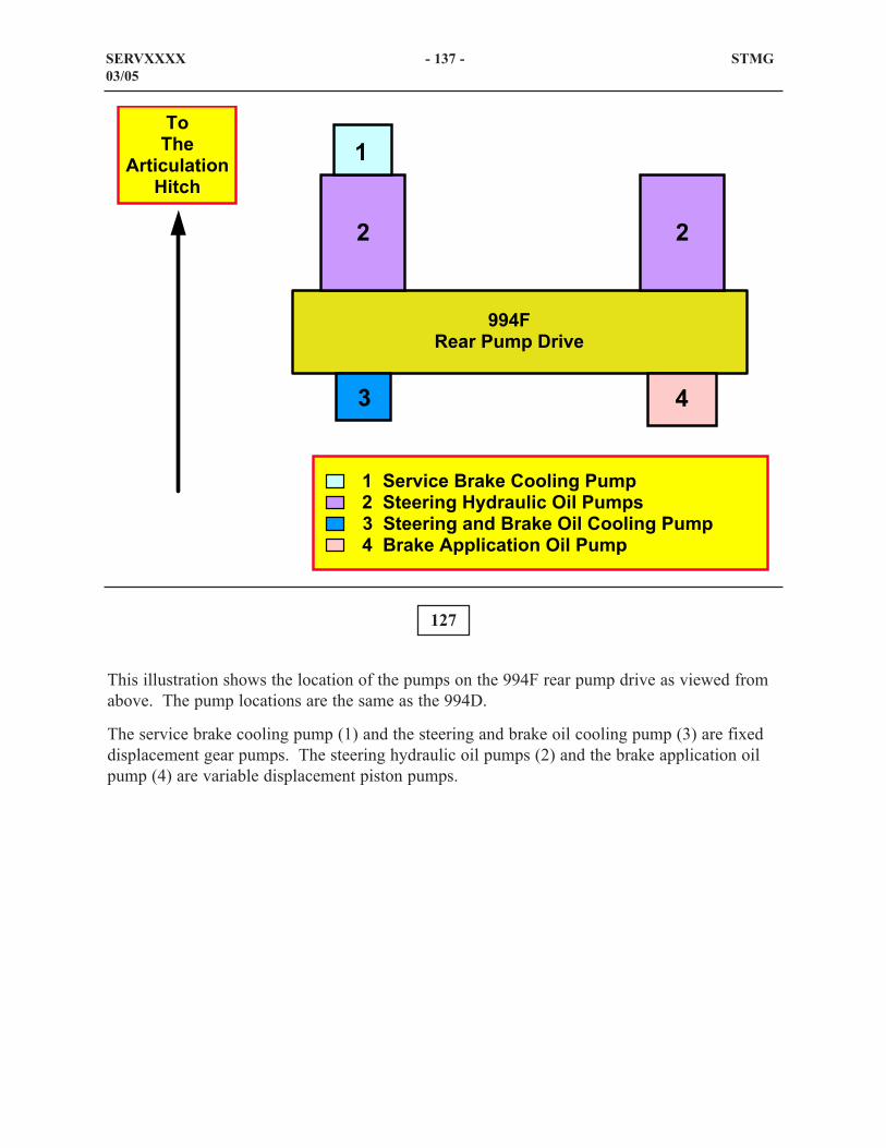
127
This illustration shows the location of the pumps on the 994F rear pump drive as viewed fromabove. The pump locations are the same as the 994D.
The service brake cooling pump (1) and the steering and brake oil cooling pump (3) are fixeddisplacement gear pumps. The steering hydraulic oil pumps (2) and the brake application oilpump (4) are variable displacement piston pumps.
SERVXXXX - 137 - STMG03/05
���
(���%���������%
++,�# ������������
���� ���% ����! �"����������;���� �����'&�����%��������������� �����&����! �����"����������,�����! �(����%�������������
; ;
,
�
�

128
The Steering System
The steering system is made up of the following components that are located on therear frame (1).
- Neutralizers and quad check valves (2)
- High pressure screens (3)
- Steering Valves (control and reducing) (4)
- Case drain filters (5)
- Steering and brake hydraulic tank (6)
- Right steering cylinder (7)
- Left steering cylinder (8)
- Steering pumps (9)
SERVXXXX - 138 - STMG03/05
23 4 5 6
7
8
9
1

The steering neutralizers and quad check valve is located at the articulation hitch between thecab and frame (EEF) (1). The bracket for the strikers (2) and (5) are attached to the loaderframe (NEEF).
The neutralizer valve is normally open between the pilot control valve (not shown) and thequad check valve. Pilot oil is allowed to flow through the neutralizer valve when the operatormoves the pilot valve to articulate the machine. When the adjusted striker makes contact withthe neutralizer, the valve will block pilot oil through the neutralizer valve. The machine willstop articulating.
In a right turn, neutralizer (3) will contact striker (2). In a left turn, neutralizer (6) will contactstriker (5).
Quad check valve (4) is between the neutralizer valves and the ends of the stem in the steeringcontrol valve (not shown). The quad check valve has two check valves for each pilot line. Onecheck valve is free flow through and the second is will block pilot oil flow to the steeringcontrol valve. When pilot oil is directed to the steering control valve, the pilot oil flowsthrough the free flow check valve. When the pilot control valve is returned to the HOLDposition, the free flow check valve will seat and block pilot oil between the check valve and thesteering control valve. The stem in the steering control valve will be held in the articulatedposition until the pilot control valve is moved in either direction. The second check valve willallow the trapped pilot oil to flow back to the pilot control valve when the valve is moved to theopposite direction (the opposite direction).
129
SERVXXXX - 139 - STMG03/05
1
2 34
56

130
This illustration shows a sectional view of the neutralizer valve.
During a less than maximum turn, oil from the steering control lever flows through theneutralizer valve to the steering control valve.
When the striker comes in contact with the neutralizer valve spool, the valve stem shifts and oilflow to the steering control valve is blocked. Pilot oil at the steering control valve flows backthrough the orifice and center passage in the spool valve to drain. The centering spring centersthe steering control valve and stops the machine from turning.
SERVXXXX - 140 - STMG03/05
��
��#�0�
"�0�#�.
1(.1
�#�/
��#
.1#
���������������� ���
��������������
���� ��
������� �����
� ��������� ������� �� �
�������� ��������
������� �����
� ��������� ������� �� �
������! ��" #��$���$��
" #��$���$��
���� ��

The upper illustration shows the case drain filters that are located in the pump bay. The lowerillustration show the high pressure screens. Access to the filters and screens is gained throughthe doors in the platform behind the cab.
The steering hydraulic system is equipped with two case drain filters (1) and (3). They filterthe oil that is in the steering pump case that will flow back to the steering hydraulic tank. Eachfilter is equipped with a bypass switch (2) and (4). The switch will send a signal to the VIMSmodule if one of the filters becomes plugged.
High pressure screens (5, 6) strain the system oil that is flowing from the steering pumps to theinlet port on the steering control valve.
131
132
SERVXXXX - 141 - STMG03/05
1 2 3 4
5 6

133
This illustration shows the location of the following components of the steering hydaulicsystem that are located on the inside of the right frame. Access these components through thedoor that is behind the cab in the platform.
Steering control valve (4) sends system oil supplied by the two steering pumps to the steeringcylinders (not shown) when a pilot oil signals the valve to shift. The steering control valve alsosends a signal to the margin spool in each pump control valve on the steering pumps.
Selector and pressure reducing valve 1 (6) reduces oil that is supplied by the steering pump tothe unloading valve in the steering control valve. Orifice (3) meters the reduced oil that flowsto the pressure switch (5). The pressure switch sends a signal to the VIMS module if theprimary steering pressure is lost. Adapter (2) is equipped with an orifice and that restricts theflow of steering pump oil to tank in order build up pressure behind the orifice to shift thediverter spool in the secondary steering valve. Also, the orifice opens a free path to dischargethe oil between the reducing valve and the diverter valve to drain in case of a loss of steeringpump oil.
Selector and pressure reducing valve 2 (1) reduces the pressure of the steering oil pressure tothe pilot pressure level. Then, that oil is directed to the pilot control valve.
SERVXXXX - 142 - STMG03/05
12 3
4
5
6

134
Shown is a schematic and sectional view of the steering pump and pump control valve.
The pump has two actuator pistons which work together to continually adjust the angle of theswashplate. The small actuator piston that that is assisted by the bias spring is used to upstrokethe pump. The large actuator piston is used to destroke the pump.
The pump control valve consists of a flow compensator (margin) spool and a pressurecompensator (cutoff) spool. The valve keeps the pump flow and pressure at a level needed tofulfill the demands of the steering system.
The margin compensator spring maintains the pump supply pressure at2100 ± 105 kPa (305 ± 15 psi) above the signal pressure. The pressure compensator springlimits the system pressure to 29000 ± 350 kPa (4200 ± 50 psi).When the engine is OFF, the bias spring in the small actuator piston moves the swashplate tomaximum angle.
SERVXXXX - 143 - STMG03/05
�� ���
����
������� ���
"������1���
���*
"��� �����
�����
�� ����
"��� �����
�����
����
������
.���
(%������
�����
�����
(%������
�����
�*�� ����
.���
(%������
�����
�3/�
�3��3�
���*
"��� �����
�����
�� ����
"��� �����
�����
�����
(%������
�����
/������(��
����/�)�����(��
����
��#�0���3/��(0��3/��"�0�#�.�1(.1
0��0����
����
%�����
1���
����������
������� ���
"������1���

135
At machine start-up, the small actuator spring holds the swashplate at maximum angle. Whenthe steering control valve is in the HOLD position, pump flow is blocked at the steering controlvalve and no signal pressure is generated. As the pump produces flow, the system pressurebegins to increase. This pressure is felt at the lower end of both the flow compensator spooland the pressure compensator spool. The flow compensator spool moves up against springforce and permits system oil to go to the large actuator piston. The oil pressure at the largeactuator piston overcomes the combined force of the bias spring and system oil pressure at thesmall actuator piston.
The large actuator piston moves the swashplate to the LOW PRESSURE STANDBY position.In LOW PRESSURE STANDBY, the pump produces enough flow to compensate for systemleakage at sufficient pressure to provide instantaneous response when the steering control valveis moved.
SERVXXXX - 144 - STMG03/05
�*�� ����
��#�0���3/��(0�
"�/�0�(��#�1(.1.�-���#��3#���(0��>
�����
(%������
�����
/������(��
����/�)�����(��
����
" ��� �����
�� ���
����
������� ���
"������1���
�����������
.���
(%������
�����
�����
(%������������
.���
(%������
�����
����
������
���*
"��� �����
�����
�� ����
"��� �����
�����
����������
���*
"��� �����
�����
�� ����
"��� �����
�����
������� ���
"������1���
����
"�����
1���

136
When the load on the steering system decreases, signal oil pressure at the right end of the flowcompensator valve decreases. This decreased pressure causes the force (flow compensatorvalve spring plus signal oil pressure) at the right end of the flow compensator spool to decreasebelow the pump supply pressure at the left end of the spool. The decreased pressure at the rightend of the flow compensator spool causes the spool to shift and allows more flow to the largeactuator causing the pressure in the large actuator piston to increase. The increased pressure inthe large actuator piston overcomes the combined force of the small actuator and bias springand moves the swashplate to a reduced angle.
As pump flow decreases, supply pressure also decreases. When the supply pressure decreasesand equals the sum of the oil pressure at the right end of the flow compensator spool and springforce, the flow compensator spool moves to a metering position and the system stabilizes.
SERVXXXX - 145 - STMG03/05
�� ���
����
������� ���
"������1���
�����������
.���
(%������
�����
�����
(%������
�����
����
"�����
1���
��#�0���3/��(0��3/��"�0�#�.�1(.1
���#�7
���*
"��� �����
�����
�� ����
"��� �����
�����
����������

137
During a turn, signal pressure at the steering control valve increases. This increased pressurecauses the force (flow compensator valve spring plus signal oil pressure) at the right end of theflow compensator spool to become greater than the pump supply pressure at the left end of thespool.
The increased pressure at the right end of the flow compensator spool causes the spool to shiftleft. The spool reduces or blocks pump output oil flow to the large actuator piston, and opens apassage to drain. Reducing or blocking oil flow to the large actuator piston reduces oreliminates the pressure acting against the large actuator piston. When the pressure in the largeactuator piston decreases, the bias spring and small actuator piston move the swashplate to anincreased angle causing the pump to UPSTROKE.
SERVXXXX - 146 - STMG03/05
�� ���
����
������� ���
"������1���
�����������
.���
(%������
�����
�����
(%������
�����
����
"�����
1���
��#�0���3/��(0��3/��"�0�#�.�1(.1
3���#�7
���*
"��� �����
�����
�� ����
"��� �����
�����
����������

138
The pressure compensator spool limits the maximum system pressure for any given pumpdisplacement. The pressure compensator spool is held in the left position during normaloperation by spring force.
When steering hydraulic system pressure is at maximum, pump supply pressure increases andthe pressure compensator spool moves right against spring force. The pressure cutoff spoolblocks oil in the large actuator piston from returning to the tank and allows supply oil to go tothe large actuator piston.
The increase in pressure allows the large actuator piston to overcome the combined force of thesmall actuator piston and spring to destroke the pump. The pump is now at minimum flow andpump supply pressure is at maximum.
This feature eliminates the need for a main relief valve in the steering hydraulic system.Maximum system pressure is adjusted by turning the pressure compensator adjustment screw.
SERVXXXX - 147 - STMG03/05
�� ���
����
������� ���
"������1���
�����������
.���
(%������
�����
�����
(%������
�����
����
"�����
1���
��#�0���3/��(0��3/��"�0�#�.�1(.1
������#��3#�"3����
���*
"��� �����
�����
�� ����
"��� �����
�����
����������

Steering Pilot Valve
The steering pilot valve (2) for the steering system is mounted below the STIC (1) on the leftside of the operator's seat. When the steering pilot valve is moved side to side, the valve directspilot oil through the neutralizer valves (not shown) to one of the ends of the directional controlvalve stem in the steering valve body (not shown).
The STIC lock lever (3) is shown in the LOCKED position. At this time, the STIC will not notmove. Push the STIC lock lever forward to the UNLOCK position in order to shift the steeringpilot valve.
139
SERVXXXX - 148 - STMG03/05
1
23

140
This illustration shows the major components in the steering pilot valve. The steering pilotvalve directs pilot oil to both ends of the stem in the steering control valve.
With the engine running and the control lever in the HOLD position, pilot oil enters the pilot oilpassage and is blocked by the pilot stems. Any return pilot oil in the lines that is between thesteering control valve and the steering pilot valve will be vented to the drain passage throughthe center of the metering stems.
SERVXXXX - 149 - STMG03/05
��#�0����.���1(.1
��&�
. ������������ �
#�� ����������� �" � ���������
# �������������
�����������
����������������
�������� �
. �������#�� ������
"��������* ��.�!��
0���3#0
# ���������
�����% �����%
�������� �

141
When the handle for the steering pilot valve is moved to the left, the cam follower linkagepushes the left port plunger downward against the regulating spring. The force of theregulating spring is greater than the return spring so the pilot stem moves downward. At thesame time, the return spring adds an upward force against the pilot stem to stabilize themovement.
When the hole through the pilot stem moves over the port from the pilot oil passage, the pilotoil flows through the center of the pilot stem. Then, the pilot oil flows through the orifice tothe quad check valve and then to the end of the stem in the steering control valve.
As the handle is moved further to the left more pilot oil is allowed to flow through the pilotstem. The pilot oil that is directed to the end of the stem will build up pressure and override theforce of the centering spring in the steering control valve (not shown) in order to move thestem. The pressure will build up a force in the center of the pilot stem. The combination of thereturn spring and that force will push upward against the regulating spring. The oil flowbetween the hole in the pilot stem and the pilot oil passage will be blocked. The pilot stem willact like a reducing valve. As more articulation speed is required, the regulating spring forcepushing down must be increased by more handle movement.
As the stem in the steering control valve is shifted, return pilot oil will be directed through theorfice in the right port, through the center of the pilot stem.
SERVXXXX - 150 - STMG03/05
��#�0����.���1(.1
��&�
. ������������ �
#�� ����������� �" � ���������
# �������������
�����������
����������������
�������� �
. ������� #�� ������
"��������* ��.�!�� .����3#0
# ���������
�����% �����%

The force that is developed by the pressure of the return oil will override the regulating spring.The pilot stem will move upward far enough to allow the return oil to flow out of the drainpassage.
NOTE: The shims that were previously used to change the adjudtment of the capsules at thebase of the valve have been removed. Also, the adjustment procedure has been changed. Toadjust the capsules, loosen the bolts that hold the steering control valve and raise the bracket.Then, rotate the capsules to the desired amount, lower the bracket over the capsules andtighten the bolts. The recommended amount of movement of the steering lever in bothdirections before the machine starts to turn is 15 ± 3 mm (0.59 ± 0.120 inch).
SERVXXXX - 151 - STMG03/05

142
This sectional view of the steering control valve identifies the various components. The controlvalve is in the HOLD position. When system oil from the steering pumps enters the steeringcontrol valve, the oil is blocked by the control stem. The oil flows through the hole in the reliefvalve and into the spring cavity. The pressue in the spring cavity will be equal to the pressureat the inlet of the control valve. The relief valve will block any oil flow between the inlet of thecontrol valve and the tank port.
The function of the control stem is to direct oil to the respective ends of the steering cylinderswhen making a turn. When in the steering control valve is in the HOLD position, the oilbetween the steering cylinders and the control valve will be blocked. System oil flow enteringthe steering valve is blocked by the control stem.
SERVXXXX - 152 - STMG03/05
"�������� �
# �� �1��� ��#�0�
"�0�#�.�1(.1��.�
����� ���������"������1��� �
�����"����'
���� �
" � ��������
"������� �# �� ��1���
�����# ���� �
#�� �����������"����'
. ������������"����'

143
This sectional view shows the steering control valve with the control stem shifted for a left turn.When the steering control lever is moved to the left, pilot oil is directed to the left turn pilotcavity. Then, the control stem is shifted to the left. System oil from the inlet of the valve flowsaround the control stem to the head end of the right cylinder and the rod end of the left cylinder.Also, the system oil flows to the ball resolver. The ball shifts to the and system oil flow aroundthe ball resolver to the steering control valve in each steering pump.
Continual movement of the steering control lever sends pilot oil to keep the steering controlspool in the open position. Steering pump oil flow is blocked at the cylinders. The pressure inthe spring chamber will increase over the relief valve setting. The force that is developed bypressure in the spring chamber exceeding the spring force on the poppet. The poppet willunseat. The force of the oil pressue in the spring cavity and the spring force will drop belowthe pressure at the valve inlet. The relief valve will shift to the right and all allow the extrapressure to flow out of the tank port. When the pressures are equalized, the poppet will seatand the the relief valve shifts to the left and stops all flow to the tank.
When an external force acts on the wheels when the control stem is in the HOLD position, ahydraulic spike is induced in the steering system. At this time the pressure at the crossoverrelief valve will open and allow the higher pressure to flow to the steering cylinder that is notbeing controlled.
SERVXXXX - 153 - STMG03/05
"�������� �
# �� �1��� ��#�0�
"�0�#�.�1(.1.����3#0
����� ���������"������1��� �
�����"����'
���� �
" � ��������
"������� �# �� ��1���
�����# ���� �
#�� �����������"����'
. ������������"����'

144
Steering Hydraulic System
When the engine is running and the steering system is in HOLD, pilot oil from the right pumpis blocked at the steering control valve spool. Oil from the left and right steering pumps flowsthrough the respective check valves to the steering control valve. The control valve spoolblocks oil flow to the steering cylinders and no signal pressure is generated.
System pressure is sensed at the margin spool, the pressure compensator spool, and the smallactuator piston (rod end symbol) of each pump . As system pressure increases, the marginspool moves against the spring force and opens a passage for pump oil to flow to the largeactuator piston (head end symbol). The pressure in the large actuator piston overcomes thecombined force of the actuator spring and the pressure in the small piston and moves theswashplate to the LOW PRESSURE STANDBY position.
In LOW PRESSURE STANDBY, the pump produces adequate flow to compensate for systemleakage and sufficient pressure to provide for instantaneous response when the steering controlvalve is moved.
The pilot steering system receives system oil from the output of the steering pumps. System oilflows from the steering pumps to the selector and pressure reducing valve 2. The valve reducesthe system pressure to pilot pressure and pilot oil flows to the steering pilot valve.
SERVxxxx - 154 - STMG03/05
� � %���
(&��� ����
# &�%��
1��� �;
�� ���
"'��& ��
"������ �
# �� �
1���
����
# ���� �
1���
. ��
0 ������K �
1���
#�� ������
"�����
1���
. �������
"������1���
" %!
1���
" %!
1���
#�� ��������
����
. ��������
����
�� �����&
���! ���!
��%!?��
# �� �
1���
��� �� ��1���
# �� �
1���
��� %����"�����������
3���& �
������
J��&
" %!�����
�� ���
�����
1��� �� ���
-����
�*��%
��#�0�
�>��/��.�
#�� �
0 ������K �
1���
� %�&��'
�� ���
����
"�����
�����
�� ���
"������1���
��� ��� ����
�%�
��� ��� ����
�%�
� � %���
(&��� ����
# &�%��
1��� ��

145
When the operator moves the STIC to the right, pilot oil flows through the pilot control valveand the right neutralizer valve to the right side of the steering control spool. Pilot oil pressuremoves the steering control spool to the right.
System oil from the steering pumps flows through the check valves and the high pressurescreens. Then, the system oil flows around the control spool to the steering cylinders. Aspressure increases in the steering cylinders, the pressure (signal pressure) is sensed in themargin valve spring chamber at each pump.
The signal pressure combines with the force of the margin spool spring and moves the marginspool down. The margin spool restricts the flow of oil to the large actuator piston (head end).The spring and pressure in the small actuator piston overcome the pressure in the large piston tomove the swashplate toward maximum angle.
The increase in swashplate angle increases pump oil flow. The increase in oil flow through thecontrol spool orifice increases the system pressure. The system pressure is sensed at the marginspool.
The increased pressure moves the margin spool against the combined forces of the spring andsignal pressure and sends oil to the large actuator piston. The actuator piston moves theswashplate to a reduced angle that produces flow relative to the position of the control spool.
SERVxxxx - 155 - STMG03/05
��#�0�
�>��/�#(�3(.�#������3#0
�� ���
"'��& ��
"������ �
# �� �
1���
����
# ���� �
1���
. ��
0 ������K �
1���
� � %���
(&��� ����
# &�%��
1��� ��
#�� ������
"�����
1���
. �������
"������1���
" %!
1���
" %!
1���
#�� �������
. �������
�� �����&
���! ���!
��%!?��
# �� �
1���
��� �� ��1���
# �� �
1���
��� %����"�����������
3���&��
������
J��&
" %!�����
�� ���
�����
1��� �� ���
-����
�*��%
#�� �����
#�� �
0 ������K �
1���
� %�&��'
�� ���
����
"�����
�����
�� ���
"������1���
���
�� ����
�%�
���
�� ����
�%�
� � %���
(&��� ����
# &�%��
1��� �;

146
When making a FULL RIGHT TURN, the right striker (not shown) contacts the rightneutralizer valve. Oil flow from the pilot control valve to the steering control valve is blockedby the movement of the neutralizer valve.
The steering control spool returns to the center position. Flow to the steering cylinders isblocked and the machine stops turning. The steering pumps return to the LOW PRESSURESTANDBY position.
The neutralizer valves prevent the machine front frame from contacting the machine rear framewhen turning FULL RIGHT or FULL LEFT. Refer to the Service Manual for the correctprocedue for any adjustments to the steering system.
SERVxxxx - 156 - STMG03/05
��#�0�
�>��/�3..�#������3#0
� � %���
(&��� ����
# &�%��
1��� �;
�� ���
"'��& ��
"������ �
# �� �
1���
����
# ���� �
1���
. ��
0 ������K �
1���
#�� ������
"�����
1���
. �������
"������1���
" %!
1���
" %!
1���
#�� �������
. �������
�� �����&
���! ���!
��%!?��
# �� �
1���
��� �� ��1���
# �� �
1���
��� %����"�����������
3���&��
������
J��&
" %!�����
�� ���
�����
1���
�� ���
-����
�*��%
#�� �����
#�� �
0 ������K �
1���
� %�&��'
�� ���
����
"�����
�����
�� ���
"������1���
���
�� ����
�%�
���
�� ����
�%�
� � %���
(&��� ����
# &�%��
1��� ��

147
The illustration shows the 994F steering system when the Secondary Steering System is active.The bi-directional secondary steering pump is splined to the output transfer gears and turnswhenever the machine is rolling.
The diverter valve directs oil from the tank to the input side of the pump and the oil from theoutput side of the pump to the main steering system depending on if the machine is rollingFORWARD or REVERSE.
The secondary steering relief valve limits the maximum pressure in the secondary steeringsystem. The unloader spool senses the pressure in the primary steering system from thepressure and selector valve 1. If there is steering system pressue, the unloader spool directssecondary steering oil to the hydraulic tank.
When the machine is rolling with the engine not running, the main steering pumps are notproviding flow to the steering system. The main steering pump output is blocked and thepressure is zero. The pressure that is acting on the top of the unloader valve is relieved. Springforce moves the unloader spool up and blocks the flow of secondary steering oil to tank. Thepressure unseats the check valve and directs secondary steering oil into the main steeringsystem. The check valves on the output of the main steering pumps seat and block the oil fromentering the pumps.
SERVXXXX - 157 - STMG03/05
��#�0�
�>��/�"�0�(#>���#�0�
� � %���
(&��� ����
# &�%��
1��� �;
�� ���
"'��& ��
"������ �
# �� �
1���
����
# ���� �
1���
. ��
0 ������K �
1���
#�� ������
"��� �����
1���
. �������
"��� ������1���
" %!
1���
" %!
1���
#�� �������
. �������
�� �����&
���! ���!
��%!?��
# �� �
1���
��� �� ��1���
# �� �
1���
��� %����"�����������
3���& �
������
J��&
" %!�����
�� ���
�����
1��� �� ���
-����
�*��%
#�� �
0 ������K �
1���
� %�&��'
�� ���
����
"�����
�����
�� ���
"������1���
� � %���
(&��� ����
# &�%��
1��� ��
���
�� ����
�%�
���
�� ����
�%�

The secondary steering oil flows to the steering control valve and the selector and pressurereducing valve. The selector and pressure reducing valve reduces the secondary steeringpressure to a pilot level. The steering pilot control valve can use that oil in order to shift thespool in the steering control valve.
The steering warning switch senses the main steering system pressure after the selector andpressure control valve. The steering warning switch is monitored by VIMS. When the mainsystem pressure drops, the switch opens. The VIMS alerts the operator with a Level 3 warningthat the main steering system pressure is low.
SERVXXXX - 158 - STMG03/05

148
The above illustration shows the location of the pumps on the 994F rear pump drive. Thepump locations are the same as the 994D.
The service brake cooling pump (1) and the steering and brake oil cooling pump (3) are fixeddisplacement gear pumps. The steering hydraulic oil pumps (2) and the brake application oilpump (4) are variable displacement piston pumps.
SERVxxxx - 159 - STMG03/05
���
(���%���������%
++,�# ������������
���� ���% ����! �"����������;���� �����'&�����%��������������� �����&����! �����"����������,�����! �����
; ;
,
�
�

149
STEERING AND BRAKE OIL COOLING SYSTEM
Shown is a block diagram of the steering and brake hydraulic oil cooling system.
The gear pump draws oil from the steering and brake hydraulic tank. Pump oil flows past thefluid sampling valve, through the filter, through the three oil cooler cores, and back to thesteering and brake hydraulic tank.
The cooler bypass valve allows pump oil to bypass the coolers at machine start-up or when theoil is cold. The cooler bypass valve is set to open at approximately 345 kPa (50 psi).
SERVxxxx - 160 - STMG03/05
++,���#�0��(0���#(7��.�"��.�0���>��/
�� �����&����!
����%��� ������
����&��������
1���
���� ��
���� ���'����
1���
����"��� �
"��� ���'����
1���
�� �� �
���� ��� �����&
���! ���!
���� �
�'����
�*��%

Steering And Brake Hydraulic Oil Cooling System
This illustration shows the location in the Engine-End-Frame of the components that are used tocool the steering and brake hydraulic oil. In the cooling system, oil is drawn from thesteering/brake hydraulic tank (1) by the gear pump (4). The oil is directed through the filtergroup (2) and then through the steering/brake oil cooler (radiator group) (3) and back to thehydraulic tank.
Also shown are the left steering cylinder (5) and the torque converter housing (6).
150
SERVxxxx - 161 - STMG03/05
12
34
5 6

The upper illustration shows the components that are in the area of the rear pump drive. Thegear pump (1) and the fluid sampling port (2) are located on the rear pump drive towards therear of the machine. The filter group is located on the right side of the machine next to thesteering and brake oil tank. Installed on the filter is the bypass switch (4). Steering oil coolerfilter bypass switch cmmunicates with the VIMS module.
Also shown is the implement hydraulic oil cooler filter.
In the lower illustration, the steering and brake oil cooler (5) is located in the radiator group atthe rear of the machine.
151
152
SERVxxxx - 162 - STMG03/05
1
2 3
4
5

153
This illustrations shows the brake component locations on the 994F Wheel Loader. The axlecomponents are retained from the 994D Wheel Loader. The service brakes now feature anincreased circuit pressure and a split control system.
SERVXXXX - 163 - STMG03/05
++,���-�.�.�(�#�#(7�"�/��00��
�� ����(&
���!�����!
� ���% ����! �1���
� ���%
���! �� ���%
���! ����!��
���!
���! �����
# ������������
���!������! �1���
���!������! �7�9
���! �(%%���������
���! ��'�� ��

154
Brake System Components
This illustration shows a schematic of the brake system with the engine not running and thepumps not rotating. The brake system component functions are:
Brake pump: The brake pump is a variable displacement piston pump with a pressurecompensated pump control valve. The pump draws oil from the steering and brake hydraulicoil tank and sends supply oil to through the check valves to the accumulators.
Check valves: Allows oil flow in one direction between the brake pump and the accumulators.
Brake accumulators: When the engine is running, the front and rear brake accumulatorssupply oil within a controlled pressure range to the brake valve and to the parking brake valve.If the engine stops running, the accumulators provide an emergency oil supply to providebraking.
Service brake valve: Controls the flow of brake oil to the front and rear service brakes.
Parking brake valve: Controls the engagement and disengagement of the parking brake.
SERVXXXX - 164 - STMG03/05
���!
� &���
� ���%
���!
1���
���!������!
1���
���!
(%%���������
. �������
� ���% ����!
���!��
���!
���! ����
"��� ��"��
�����
���!
"�����
����
�� �� �
�� �� �
1����9�
������% � �
����������
�� ����
"������1���
����
(%������
�� �����&
���! ��'&�����%�������!
++,��#(7��>��/0��0�0���#300�0�
�(#7�0���#(7�0�(���#1�"��#(7��0���0�(��
���! �.�*��� ����
-������*��% �
#�� ������
� ���% ����!
#�� ��# ��
� ���% ����!
. ���# ��
� ���% ����!
" %!
1���
���!��
���!
�� ����
�*��% ���!��
����!
�� ���%!
��*��%
���! �"�����
������!

Parking brake: Prevents the machine from moving when parked.Parking brake pressure switch: The pressure switch sends a signal to the Power Train ECMif a low pressure event occurs at in the parking brake circuit.
Brake low pressure warning switches: The pressure switch sends a signal to the VIMSmodule if a low pressure event occurs at either brake accumulator.
SERVXXXX - 165 - STMG03/05

155
BRAKE SYSTEM
Brake System Schematic
Shown is a schematic of the service brake system, the parking brake system, and the brakecooling system.
In the illustration, the parking brake is disengaged and the service brakes are not engaged.
SERVxxxx - 166 - STMG03/05
���!
� &���
� ���%
���!
1���
���!������!
1���
���!
(%%���������
. �������
� ���% ����!
���!��
���!
���! ����
"��� ��"��
�����
���!
"�����
����
�� �� �
�� �� �
1����9�
������% � �
����������
�� ����
"������1���
����
(%������
�� �����&
���! ��'&�����%�������!
++,��#(7��>��/
0��0�#300�0��(#7�0���#(7����0�(���#1�"��#(7��0���0�(��
���! �.�*��� ����
-������*��% �
#�� ������
� ���% ����!
#�� ��# ��
� ���% ����!
. ���# ��
� ���% ����!
" %!
1���
���!��
���!
�� ����
�*��% ���!��
����!
�� ���%!
��*��%
���! �"�����
������!

156
Brake System Schematic
Shown is a schematic is the service brake system, the parking brake system, and the brakecooling system.
In the illustration, the service brakes are engaged and the parking brake is disengaged.
SERVXXXX - 167 - STMG03/05
���!
� &���
� ���%
���!
1���
���!������!
1���
���!
(%%���������
. �������
� ���% ����!
���!��
���!
���! ����
"��� ��"��
�����
���!
"�����
����
�� �� �
�� �� �
1����9�
������% � �
����������
�� ����
"������1���
����
(%������
�� �����&
���! ��'&�����%�������!
++,��#(7��>��/
0��0�#300�0��(#7�0���#(7����0�(���#1�"��#(7��0�(��
���! �.�*��� ����
-������*��% �
#�� ������
� ���% ����!
#�� ��# ��
� ���% ����!
. ���# ��
� ���% ����!
" %!
1���
���!��
���!
�� ����
�*��% ���!��
����!
�� ���%!
��*��%
���! �"�����
������!
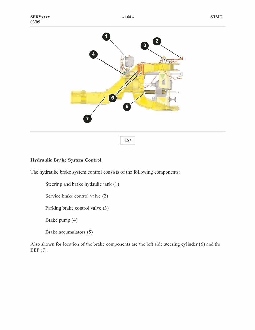
Hydraulic Brake System Control
The hydraulic brake system control consists of the following components:
Steering and brake hydaulic tank (1)
Service brake control valve (2)
Parking brake control valve (3)
Brake pump (4)
Brake accumulators (5)
Also shown for location of the brake components are the left side steering cylinder (6) and theEEF (7).
157
SERVxxxx - 168 - STMG03/05
12
3
4
56
7

This illustration shows the service brake valve (3) and the parking brake control valve (4). Theservice brake control is attached below the cab frame at the articulation hitch.
The parking brake valve group is located one EEF at the articulation hitch. Installed on theparking brake control valve group is the parking brake interlock switch (7) and the parkingbrake pressure switch (5). These two switches communicate with the Power Train ECM.
Service brake low pressure switches (1) and (2) are installed in the brake lines between theservice brake control valve and the brake accumulators (not shown). Front brake pressureswitch (2) and the rear brake pressure switch (1) communicate a drop in pressure to the VIMSmodule.
Also, hose (8) is connected to the rear service brakes in the EEF (not shown), hose (9) isconnected to the front service brakes in the NEEF (not shown), and hose (6) is connected to theparking brake in the NEEF (not shown).
158
SERVxxxx - 169 - STMG03/05
12
3
4
5
678
9

159
This illustration shows the service brake valve operation with the right service brake pedalapplied and also not applied.
When the operator depresses either brake pedal (right view), the upper spring moves the twobrake spools down. The brake spools close the passages to the tank and open the passages fromthe two accumulators. The oil from the rear accumulator flows through the upper brake spoolto ENGAGE the rear service brakes and to fill the chamber between the upper brake spool andthe lower brake spool. The oil from the front brake accumulator flows through the lower brakespool to ENGAGE the front service brakes and to fill the chamber at the bottom of the lowerspool.
The pressure at the bottom of the lower brake spool and the force of the spring move the lowerbrake spool up against the pressure in the chamber between the upper brake spool and the lowerbrake spool. The pressure in the chamber between the upper brake spool and the lower brakespool moves the upper brake spool up against the force on the brake pedal.
The force at the bottom of each brake spool balances that brake spool against the force at thetop of the brake spool. Each brake spool acts as a pressure reducing valve to limit the pressurein the brakes proportionally to the force at the top of the respective brake spool.
SERVXXXX - 170 - STMG03/05
���#(#��#(7�
����#�0���#(7�
�#(7���(.
(��.��
3��#�����.��#�0��
�#�/
(""3/3.(��#
�#�/
(""3/3.(��#
�#(7���(.
���
�����0
.�-#�����.
��#�0�
�#1�"��#(7�1(.1
����(07 ����(07
���#(#��#(7�
����#�0���#(7�

When the brake pedal is RELEASED (left view), the oil passages from the accumulators to thebrakes are closed, and the passages from the brakes to the tank are opened. Oil in the rear andfront service brakes flows through the respective brake spools to the tank. Spring force at thebottom of the lower brake spool moves the brake spools up.
SERVXXXX - 171 - STMG03/05

This illustration shows the service brake accumulators and the check valves. Accumulator (2)and check valve (4) is in the circuit for the front service brakes. Accumulator (1) and checkvalve (6) is in the circuit for the rear service brakes.
The accumulators are piston type that is charged with dry nitrogen. The charge pressure for theaccumulators at 160 °C (70 °F) is 5520 ± 280 kPa (800 ± 40 psi).
Also, hose (5) is the supply line that is feeding the two accumulators. The hose is installedbetween the brake pump (not shown) and the divider block (5).
160
SERVxxxx - 172 - STMG03/05
12
3
4 5 6

This illustration shows the location of the brake pump (4) and the check valve (9) on the rearpump drive (6). The brake pump is a pressure compensated piston pump that is adjusted tosupply 16000 ± 345 kPa (2300 ± 50 psi) pressure. The check valve has a cracking pressure of448 ± 55 kPa (65 ± 8 psi).
Also shown is the steering and brake hydraulic tank (1) and brake cooling tank (5). Installed onthe steering and brake hydraulic tank are the temperature sensor (3) and the liquid level switch(2) (the liquid level switch is located on the opposite side of the tank). Temperature sensor forthe steering and brake hydraulic oil (3) reports to J2-54 on the VIMS module. Liquid levelswitch (2) for the oil in the steering and brake hydraulic tank reports to the VIMS module.
Also shown are the steering and brake oil cooling pump (8) and the hose (7) that is connectedto the dividing block for the brake accumulators (not shown).
161
SERVxxxx - 173 - STMG03/05
1 2
3
45
6 7
8 9

162
Brake Pump
Shown in this illustration are the main components of the brake pump.The components are:
- Pump control valve
- Control piston
- Spring
- Swashplate
- Piston assembly
- Barrel
- Drive shaft
When pressure in the brake system is less than 16000 ± 345 kPa (2300 ± 50 psi), the springkeeps the swashplate at maximum angle. The pump piston stroke is longest and pumpdisplacement is maximum. A small amount of pressure oil from the outlet passage flows to thepressure compensator. A spool in the pressure compensator blocks the flow of oil to the control
SERVXXXX - 174 - STMG03/05
�����"������1���
"�����������
"�����������
������
�����
�*�� ���� ������(�� �9�'
���� �� ���
���� �
���� �������� �
�� ��������
�#(7��3/�.�-��#��3#

163
This illustration shows the main components and the operation of the pump control valve. Thecomponents are:
- Adjustment bolt
- Locknut
- Spring
- Pressure compensator pool
The left illustration shows the operation of the pressure compensator valve when the brakesystem pressure is less than 16000 ± 345 kPa (2300 ± 50 psi). Pump output oil flows aroundthe right land of the pressure compensator spool and into the chamber at the right end of thespool.
When the brake system pressure increases to 16000 ± 345 kPa(2300 ± 50 psi), the pressure of the oil in the chamber is high enough to move the spool againstthe spring. Movement of the spool permits oil to flow past the spool to the control piston in thepump.
SERVXXXX - 175 - STMG03/05
(&6���� �
����
.�%!���0�� �� ���� �"��� ������������
���������
���� �
���"�����
�����
(&6���� �
����
.�%!���0�� �� ���� �"��� �����������
���������
���� �
���"�����
�����
.�-��#(7��>��/���#��3# ������#(7��>��/���#��3#
�3/��"�0�#�.�1(.1�

164
When the brake system pressure reaches 16000 ± 345 kPa (2300 ± 50 psi), oil from the pumpcontrol valve fills the chamber in the control piston. As the brake system pressure increasesabove 16000 ± 345 kPa (2300 ± 50 psi), the oil pressure from the pump control valve movesthe control piston against the control spring. This movement decreases the angle of theswashplate, the stroke of the pistons, and the displacement of the pump. The amount of oil perpump revolution is decreased to the amount needed to maintain the system pressure at 16000 ±345 kPa (2300 ± 50 psi).
SERVXXXX - 176 - STMG03/05
�����"������1���
"�����������
"�����������
������
�����
�*�� ���� ������(�� �9�'
���� �� ���
���� �
���� �������� �
�� ��������
�#(7��3/�������#��3#

This illustration shows the brake pads and spacers being assembled into the final drive.
165
SERVXXXX - 177 - STMG03/05
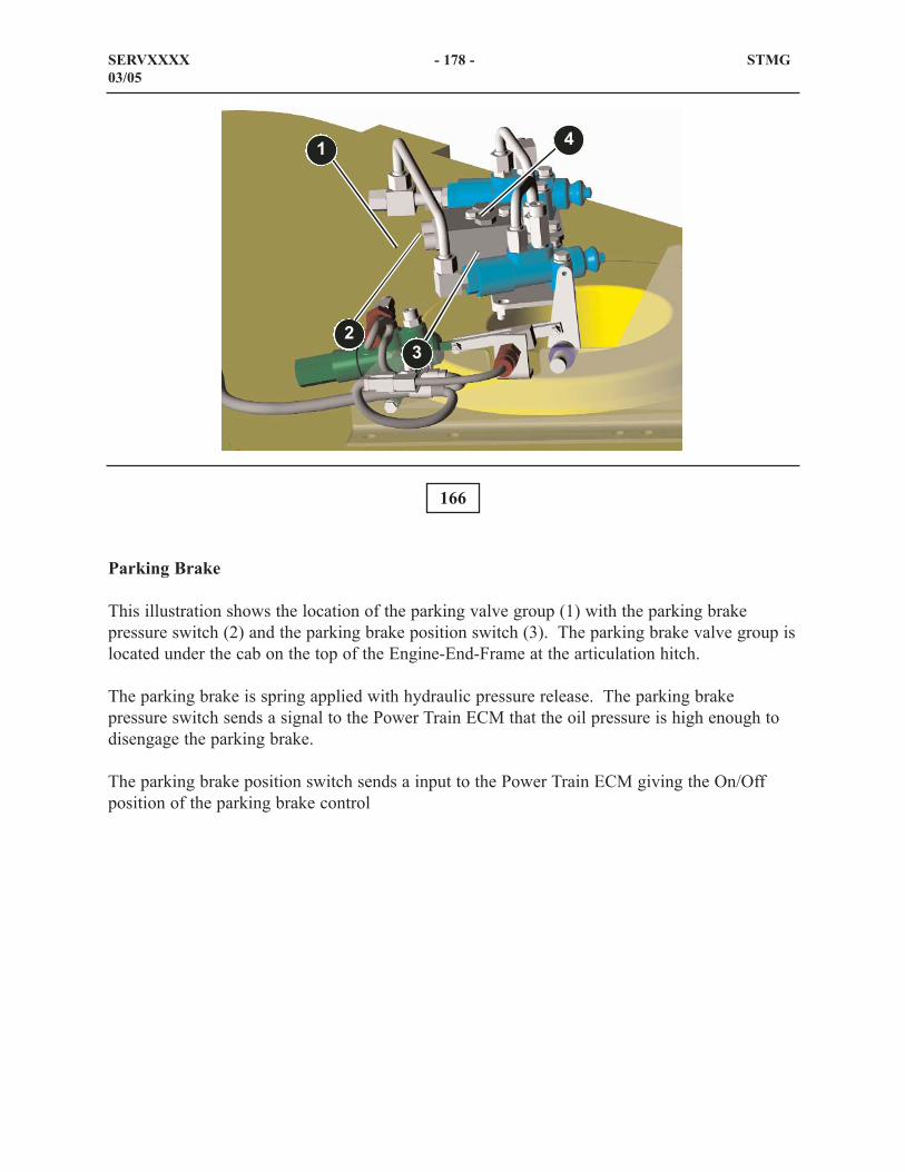
Parking Brake
This illustration shows the location of the parking valve group (1) with the parking brakepressure switch (2) and the parking brake position switch (3). The parking brake valve group islocated under the cab on the top of the Engine-End-Frame at the articulation hitch.
The parking brake is spring applied with hydraulic pressure release. The parking brakepressure switch sends a signal to the Power Train ECM that the oil pressure is high enough todisengage the parking brake.
The parking brake position switch sends a input to the Power Train ECM giving the On/Offposition of the parking brake control
166
SERVXXXX - 178 - STMG03/05
1
23
4

The parking brake assembly (2) is located at the articulation hitch on the loader frame (1). Theparking brake is spring activated and hydraulic oil pressure released through cylinders (3). Thecylinders are equipped with air purge screws (4).
167
SERVXXXX - 179 - STMG03/05
12
3
4

The front axle (1) and the rear axle (3) are equipped with temperature sensors. The pressuresensor (2) and the pressure sensor (4) report the temperature of the respective axles to theVIMS module through a PWM signal. The VIMS module interputs the information and reportsa warning if necessary to the operator panel.
168
169
SERVXXXX - 180 - STMG03/05
2
1
3
4

Brake Oil Cooler System
The hydraulic brake system control consists of the following components:
Brake oil cooler tank (1)
Brake cooler pump (2)
Brake oil cooler (3)
Engine-End-Frame (4)
Also shown is the transmission (5).
170
SERVxxxx - 181 - STMG03/05
12
3 45

Brake Oil Cooler System
This illustration shows the line routing through the Non-Engine-End-Frame
The brake oil cooler system in the NEEF consists of two hoses that are connected to the frontaxle (not shown). Hose (5) directs flow to the divider block (not shown) on the front axle.Hose (4) is the return line to the brake oil cooler tank that is located in the Engine-End-Frame.
Also shown is the implement hydraulic oil tank (1) and the front pump drive (2) on the loaderframe (3).
171
SERVxxxx - 182 - STMG03/05
1 2
3
4 5

The screens (2) for the front service brakes are mounted to the front axle housing. Each screenhas a check valve (1) not shown to prevent oil from flowing in the reverse direction.
The brake cooling screens are canister type screens with replaceable 500 micron elements.
172
SERVxxxx - 183 - STMG03/05
1
2
1
2

This view shows the screen (arrow) for the right rear wheel brake cooling circuit. It is mountedto the axle housing between the axle housing and the trunion.
The rear brake cooling screens are also equipped with check valves (not shown) to prevent theoil from flowing in the wrong direction.
The rear brake cooling screens are also canister type screens with replaceable 500 micronelements.
173
SERVxxxx - 184 - STMG03/05

This illustration shows the screen (arrow) for the rear left wheel brake cooling circuit. It ismounted to the axle housing between the axle housing and the trunion. The rear brake coolingscreens are also equipped with check valves (not shown) to prevent the oil from flowing in thewrong direction.
174
SERVxxxx - 185 - STMG03/05

The 994F Wheel Loader can be equipped with an optional rear vision camera. The camera thatis mounted on the rear of the machine gives the operator a look at what is behind the machine.
The upper illustration shows the location of the rear vision camera at the rear of the EEF. Theoperator can view what is behind the machine through the display in the cab (shown in thelower illustration).
175
176
SERVXXXX - 186 - STMG03/05

177
Hydraulic Schematic Color Code
The table above shows the color code for hydraulic schematics and cross-sectional views thatare shown in this presentation.
SERVXXXX - 187 - STMG03/05
���!����'�?�"���*�'�� %���
.�� �����'�?�������% �%�����
# &�?���� ��� ���� ����
# &8- �� ������ ��?�������� ���� �� &�%���
# &�"���� ��% �?�;&�� &�%�������� ����
��!�?���&�� &�%�������� ����
# &8��!������ ��?�� %�&��'�����% ������� ����
���� �?������I������I�������$� �"�� �� �����
���� 8- �� ������ ��?
# &�% &������I������I�����"������� ����
�� �?���!I�����I����� ������� ��� �?������ &����
���*�?�.�9��%��������
����� �?�� �����%��� ���� �
���� �"���� ��% �?�;&�� &�%�����
�����I������I�����"������� ���� G
- �� �?��(����� � ���
(���<���� ���� =
> ���*�?�/���������%����� &�%���� ���
"���> ���*�?�<� ����%� &����� =
�& ����%��������%���� ��
*�� ����������������
���%!�?�/ % ��%���%� %�������� ���
�� 8- �� ������ ��?
�%�� � ���������'&�����%�1��&
�>�#(3.�"��"�/(��"�"�.�#�"��