Embed Size (px)
Citation preview
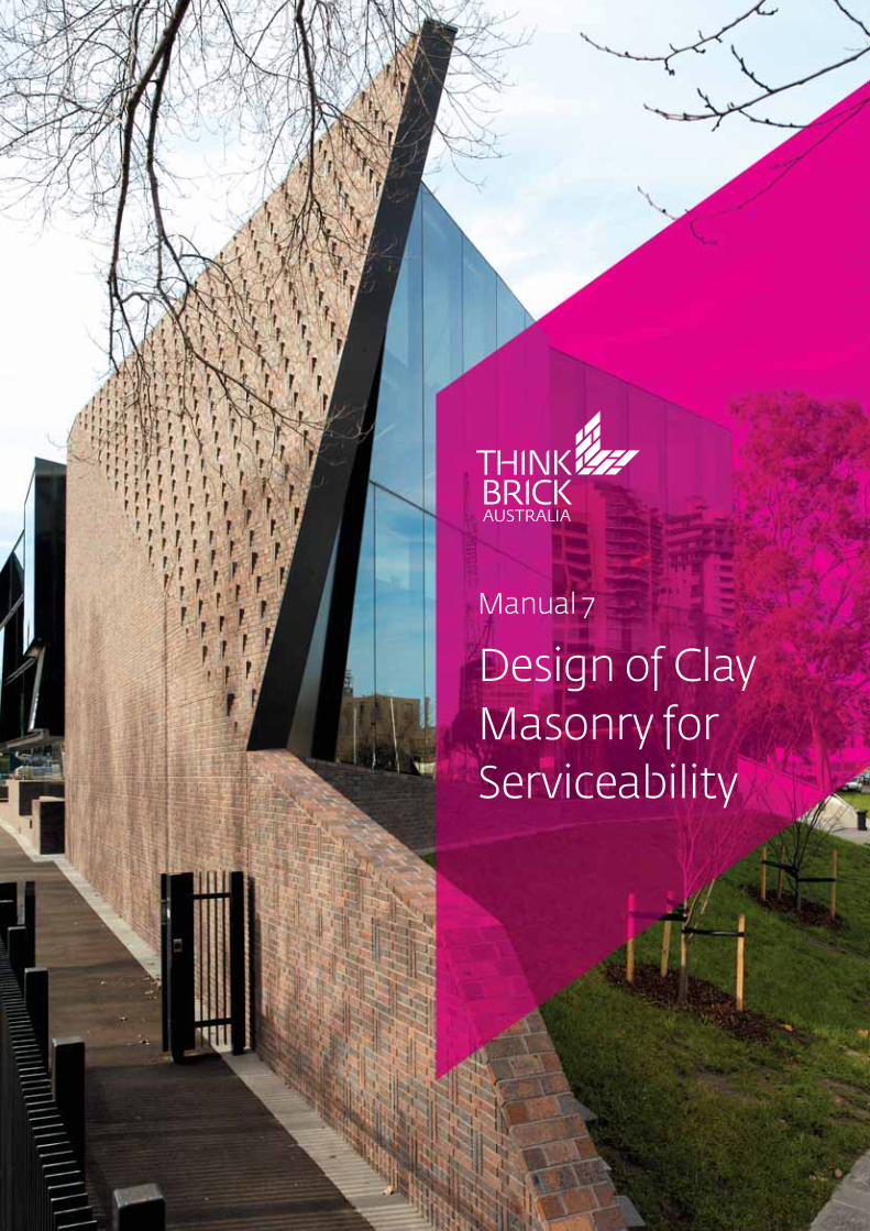
Manual 7
Design of ClayMasonry forServiceability
This publication updates and supersedes the publication of the same name published by the Clay Brickand Paver Institute in October 2001.
While the contents of this publicationare believed to be accurate and complete, the information given isintended for general guidance and does not replace the services of professional advisers on specific projects. Local or state regulations may require variation from the practices and recommendations contained in this publication. ThinkBrick Australia disclaims any liabilitywhatsoever regarding the contents of this publication.
This publication, its contents and format are copyright © 2009 of Think Brick Australia and may not be reproduced, copied or stored in anymedium without prior, written authorisation from Think BrickAustralia. ABN 30 003 873 309.
Cover: Melbourne Grammar School’sNigel Peck Centre for Learning andLeadership creates a new campus entryas well as consolidating library facilitiesand providing lecture theatre and seminar spaces. The elaborate brickpatterning of the book stack pavilioncontinues above the ‘fold,’ with a singleshaped brick allowing a seamless transition. Book-like vertical bricks project at the upper level. Bricks byDaniel Robertson Australia, design byJohn Wardle Architects, construction by Probuild Constructions, bricklayingby Deca Constructions. Photograph by Roger du Buisson.
Published October 2009
Prepared by Dr Stephen Lawrence,SPL Consulting Pty LtdProfessor Adrian Page,The University of Newcastle
PO Box 6567, Baulkham Hills Business Centre NSW 2153, Australia
Telephone (02) 9629 4922 Fax (02) 9629 7022
www.thinkbrick.com.au
12
3
Introduction 7
The Use of Clay Masonry in Structures 8
2.1 General 8
2.2 Houses 8
2.3 Multiple-occupancy domestic units 8
2.4 Low-rise commercial and industrial buildings 8
2.5 Multi-storey framed structures 8
2.6 Types of masonry elements 9
2.6.1 General 9
2.6.2 Loadbearing walls 9
2.6.3 Veneer walls 9
2.6.4 Cavity walls 9
2.6.5 Single-skin walls 10
2.6.6 Masonry infill panels 10
2.6.7 Piers 10
2.6.8 Freestanding elements 10
2.6.9 Other wall types 10
Masonry Properties 11
3.1 General 11
3.2 Masonry units 11
3.2.1 Category and type 11
3.2.2 Dimensions 11
3.2.3 Compressive strength 11
3.2.4 Lateral modulus of rupture 12
3.2.5 Salt attack resistance grade 12
3.2.6 Coefficient of expansion 12
3.3 Mortar properties 12
3.4 Masonry properties 12
3.4.1 Compressive strength 12
3.4.2 Tensile strength of masonry 13
3.4.3 Shear strength of masonry 13
3.4.4 Elastic modulus 13
3.4.5 Density 14
3.4.6 Bedding 14
3.5 Wall ties and connectors 14
3.6 Damp-proof courses and flashings 14
ContentsClick on any entry
4
5
6
7
8
9
Causes of Masonry Cracking 15
4.1 Introduction 15
4.2 Cracking due to external effects 16
4.2.1 General 16
4.2.2 Moisture movement in reactive soils 17
4.2.3 Differential settlement of foundations 18
4.2.4 Mine subsidence 18
4.2.5 Extreme loading 18
4.3 Cracking from dimensional changes in masonry 18
4.3.1 General 18
4.3.2 Thermal changes 19
4.3.3 Wetting and drying changes 19
4.3.4 Long-term permanent expansion in clay products (brick growth) 19
4.3.5 The Influence of render 20
4.4 Cracking from interaction with other structural elements 21
Design to Avoid Cracking 22
5.1 General 22
5.2 Foundation design 22
5.3 Masonry quality 23
5.3.1 General 23
5.3.2 Bond strength 23
5.4 Masonry detailing 24
5.4.1 General 24
5.4.2 Locations of articulation joints 24
5.4.3 Detailing of articulation joints 25
5.4.4 Control joints 26
5.5 Isolation and slip joints 26
Crack Repair Techniques 27
6.1 Introduction 27
6.2 Stabilisation of the cause of cracking 27
6.3 Repair methods 27
6.3.1 Raking and re-pointing 27
6.3.2 Reconstruction of selected areas 28
6.3.3 Epoxy injection 28
Design for Durability 29
7.1 General 29
7.2 Masonry units 30
7.3 Mortar 31
7.4 Ties, connectors and lintels 31
7.5 Reinforcement 32
Robustness 33
8.1 Design principles 33
8.2 Limiting dimensions for robustness 33
References 39

Figures
1. Crack types in masonry 16
2. Typical cracking from a doming foundation 17
3. Typical cracking from a dishing foundation 17
4. Cracking at offsets and corners caused by expansion 19
5. Oversailing of DPC caused by expansion 19
6. Failure of biscuit bricks caused by bowing and restrained expansion 19
7. Effect of foundation movement on articulated walls (doming foundation) 24
8. Effect of foundation movement on articulated walls (dishing foundation) 24
9. Typical methods of sealing articulation and control joints 25
10. Typical flexible masonry anchors for articulation joints 26
11. Typical slip joint between brickwork and a concrete slab 26
12. Salt attack damage to clay masonry units 30
13. Salt attack damage to mortar 30
14. Corroded tie exposed by a failure during the Newcastle earthquake 31
Click on any entry
1. Masonry wall damage classification 15
2. Relative differential movement limits for footings and rafts supporting houses 22
3. Recommended maximum spacing of articulation joints in walls up to 2.7m high 25
TablesClick on any entry
1. Robustness limits for clay masonry walls supported on four edges and loaded by a concrete slab 34
2. Robustness limits for clay masonry walls supported on four edges and loaded by other than a concrete slab 35
3. Robustness limits for clay masonry walls supported on three edges and with the top free 35
4. Robustness limits for clay masonry walls with one side free and loaded by a concrete slab 36
5. Robustness limits for clay masonry walls with one side free and loaded by other than a concrete slab 36
6. Robustness limits for clay masonry walls supported on two edges 37
7. Robustness limits for clay masonry walls supported at top and bottom and loaded by a concrete slab 37
8. Robustness limits for clay masonry walls supported at top and bottom and loaded by other than a concrete slab 38
ChartsClick on any entry
This manual provides guidance forthe serviceability design of claymasonry in buildings. The guidanceis of a general nature and represents industry recommendations for good practice. Alternative methods,where they exist, might be preferred in some situations forarchitectural, geographical orother reasons.
In conjunction with this manual,appropriate reference should bemade to the Building Code ofAustralia (BCA)1 and the various relevant Australian standards,including Masonry Structures (AS 3700)2 with its Commentary3,Masonry in Small Buildings: Design(AS 4773.1)4 and Masonry in SmallBuildings – Construction (AS 4773.2)5. (Both standards arepending publication.)
For structures to remain serviceable, their deflections andany tendency to crack must becontrolled. Little guidance is givenin the standards on appropriatedeflection limits, but the robustness provisions in AS 3700for individual walls and piers aredesigned to restrict the sizes ofmembers to ensure that serviceability will be satisfactory.There is also a range of semi-empirical procedures to minimisecracking from external effects andthese are discussed in this manual.
Appropriate load factors and thedesign provisions of AS 3700should be used to check serviceability limit states for particular load conditions imposed on the structure, such as serviceability wind loading.
The following movements shouldbe considered in design for serviceability:
• Expansion or shrinkage of themasonry caused by moisture
• Thermal expansion or contraction
• Deflection, creep and othermovements in associated materials
• Foundation movements
• Deformations during the construction process
Calculation of deflections inmasonry structures must be inaccordance with accepted engineering principles and the relevant properties of the materials. The code AS 3700 givesvalues for elastic modulus that canbe used for serviceability design.
The primary means of controllingcracking in masonry structures arethe use of footings with adequatestiffness and the inclusion of control joints, the design of whichis discussed in this manual. Whilesome minor cracks can often betolerated, crack widths should bekept to a minimum for aestheticreasons and to avoid jeopardisingdurability, especially in reinforcedmasonry.
1. Introduction
Design of Clay Masonry for Servicability / 7

2.1 General
Clay masonry is a versatile mediumthat is used for a wide variety ofstructures. Design for serviceabilityis important for all types of structure, although differentaspects of design will assume primary importance for differentstructural types. The followingsummarises the various types ofconstruction where clay masonry is used and the various structuralelements that are employed.
2.2 Houses
The most common form of domestic construction in Australiais the single-occupancy house. Thevast majority of these are clad withclay masonry, with brick-veneerthe most popular form of construction in the eastern states.Full-brick cavity construction ispopular in Western Australia andsingle-leaf construction using hollow units is popular in northQueensland. Because the walls ofhouses generally support only alight roof load or no load at all, thecritical design condition is usuallylateral load from wind or earthquake.
In a veneer-wall house, the frame(timber or steel) is relied upon toresist the main forces, includingvertical (gravity) forces and lateralshear from wind and earthquake.On the other hand, in a cavity-wallhouse and single-leaf construction,the masonry walls must providethe resistance to all lateral forces,usually by in-plane shear. The lattercan be the governing action whereearthquake forces are high.
The most common serviceabilityproblems with masonry houses arecracking (caused by foundationmovements) and durability failures. Means of preventing theseare discussed later in this manual.
2.3 Multiple-occupancydomestic units
Loadbearing masonry structuresgreater than four storeys in heightare common in other parts of theworld (for example Europe) andhave been built in Australia in thepast. However, because of theincreased emphasis on earthquakeloading, the vast majority of multiple-occupancy units inAustralia are less than five storeysin height.
Multiple-occupancy domestic unitsof loadbearing masonry (commonly called three or four-storey walk-ups) are commonin Australia and two-storey semi-detached townhouses are becoming increasingly popular. Inthese buildings, the masonry wallsusually support concrete floorslabs and the roof structure, andthe wall sizes are determinedaccordingly. However, wall designscan be governed by resistance toout-of-plane forces, especially inthe upper storeys.
In these structures, the masonrywalls must also provide the resistance to lateral in-plane(shear) forces from wind or earthquake, with the floor and roofacting as diaphragms to distributeforces to the walls. This requires acellular form of structure.
When serviceability problemsoccur with these structures theytend to be related to differentialmovement (dimensional changes)or durability; these are discussedlater in this manual.
2.4 Low-rise commercialand industrial buildings
Where masonry panels are used ascladding for commercial and industrial buildings their structuraldesign is usually governed byresistance to wind and earthquakeforces. Economy in design is vitalfor these walls. The design flexibility, aesthetics and excellentfire resistance of masonry make itan ideal material for these applications.
In these buildings, the frame ofconcrete or steel provides the overall resistance to lateral forcesand the walls must have sufficientflexural resistance to span betweenframe members and other supports. Deflection compatibilitybetween frames and walls is animportant consideration and, if nottreated properly, is the main causeof serviceability problems for thesestructures.
2.5 Multi-storey framedstructures
Masonry cladding is popular formulti-storey structures where theframe is made of reinforced concrete or steel. In these cases,the walls provide the envelope toprotect the interior against theweather and are only required toresist lateral out-of-plane wind andearthquake forces, which are then
2. The Use of Clay Masonry in Structures
Design of Clay Masonry for Servicability / 8
transferred by the connections tothe supporting frame. Often, theinner leaf is an infill wall tied to theframe. The external leaf is usually aveneer, supported by angles or nibson the floor slabs. Masonry is alsoextensively used for internal partition walls in these buildings.
The walls in the upper storeys ofmulti-storey buildings can be subjected to high wind loadsbecause of their height above theground and this will usually governtheir design.
The main sources of serviceabilityproblems for masonry in thesestructures are improper treatmentof joints, inadequate tyingbetween the masonry and thestructural frame and insufficientprovision for differential movement, especially relating tolong-term moisture expansion ofclay masonry.
2.6 Types of masonry elements
2.6.1 GeneralVarious types of masonry elementsare used to make up a typicalmasonry structure. These includewalls (which might be of veneer,cavity, solid or diaphragm construction), piers and freestanding elements such asparapets and chimneys. These various types of elements behavein different ways and their designmust take into account their particular characteristics.
The types are briefly described inthis section as background to thelater discussion of serviceabilitydesign.
2.6.2 Loadbearing wallsLoadbearing walls rely on theircompressive load resistance tosupport other parts of the structure. Buckling and crushingeffects, which depend on the wall slenderness and interaction withthe slab or roof above, determinethe compressive capacity of a wall.Compressive strength is influencedby the shape of the units,particularly the presence and sizeof hollow cores. External loadbearing walls will usually be of cavity construction (see Section2.6.4) to ensure adequate waterpenetration resistance, but single-skin walls are used in someareas.
2.6.3 Veneer wallsUnreinforced masonry is widelyused as a veneer in residential,light commercial and multi-storeyframed construction. Veneer wallsconsist of a single skin of masonryattached to a timber or steel frameby wall ties. Clay brick is by far themost common choice of masonryfor veneer walls.
As the name suggests, the veneeris non-structural, so that the backing frame must be designed to resist the total applied load.Although they are non-structural,veneers are nevertheless subject towind and earthquake loading. Inparticular, the seismic performance of veneers is important because of their widespread use and the high costof repair if their performanceproves to be inadequate. Any lateral loads on the veneer must betransferred to the structural frameby the wall ties, which thereforeplay an essential role. The ties must
have adequate strength and stiffness, and be located at anappropriate spacing to transfer theload effectively. Attention must alsobe given to the durability of the tiematerial.
A veneer wall relies on flashing anddamp-proof courses, in conjunctionwith weep-holes, to act as an effective barrier to moisture entering the building. The presenceof flashing and a damp-proof coursewill influence behaviour under lateral load.
It is important to note thatalthough veneer walls are non-structural, they still have the potential to crack from the causesdescribed in Section 4, and must be detailed and constructed accordingly.
2.6.4 Cavity wallsCavity wall construction is a traditional form of building, whichis still common in some parts ofAustralia. It provides a wall havinggood thermal and strength properties, without the need tomaintain an external coating.Cavity walls are constructed of twoleaves of masonry separated by acavity, which is typically 50mm inwidth and is intended primarily toprevent water penetration into thebuilding. The two leaves are connected by wall ties. Usually onlyone of the leaves is loadbearing(normally the inner leaf). The twoleaves can be of different materialsand thicknesses. As for the case ofveneer walls, the non–loadbearingleaf must be adequately supportedby wall ties so that lateral loads areeffectively transmitted to the loadbearing leaf.
Design of Clay Masonry for Servicability / 9
In resisting applied loads normal tothe face, cavity walls rely on theinteraction between the two leavesthrough the ties. Behaviour of thewhole system is complex and adetailed structural analysis wouldbe required in order to predict accurately the forces in individualcomponents. This is usually impractical and simplified rules areemployed to design the masonryleaves and the ties. Essentially, theties act as springs to transmit axialforces only.
Proper detailing of flashings,damp-proof courses and weep-holes is essential to ensure that acavity wall remains an effectivewaterproof barrier. As for the caseof veneer walls, the presence offlashing and a damp-proof coursewill affect behaviour under lateralload.
Cavity walls must be suitablydetailed to avoid distress andcracking in the masonry from thecauses described in Section 4.
2.6.5 Single-skin wallsThis form of construction has beenused in recent years, particularly innorthern Australia, utilizing hollowclay units similar to traditional hollow concrete units. A singleloadbearing leaf of masonry is usedfor the external walls and waterpenetration is prevented by the useof suitable coatings or render onthe surface of the masonry, oftencombined with a roof system incorporating overhanging eaves.In cyclonic areas, hollow clay unitscan be used to permit partial or full wall reinforcement by incorporating reinforcing steel inthe cores of the hollow units.Hollow units also accommodatethe roof tie–downs that extendfrom the roof to the footing system.
2.6.7 PiersMasonry piers can either be isolated (supporting a slab) orengaged (providing enhanced loadresistance to a wall). Isolated piersare designed for compressive loadcapacity in the same way as loadbearing walls. The effect ofengaged piers is taken intoaccount by the use of an effectivethickness for the wall/pier combination.
2.6.8 Freestanding elementsParapets and other freestandingelements are commonly used inunreinforced masonry structures.Because of the low flexuralstrength of the masonry, these elements have little resistance tolateral load and must rely on gravity for stability. The presence ofa flashing or damp-proof course atthe base exacerbates the situation.In addition, these elements areusually located at or near the topof the structure where the windloading is highest and the effects of seismic ground motion are magnified by the dynamic responseof the building.
It is desirable to avoid the use offreestanding elements, or, if theymust be used, for them to be supported or locally reinforced toprovide flexural strength.
2.6.9 Other wall typesThere are various other structuralforms for walls, includingdiaphragm walls, zigzag orchevron walls, fin walls, and wallswith staggered engaged piers in acavity space. These forms are usually used when it is necessaryto achieve a high resistance to lateral out-of-plane load.
Single-skin walls rely on the external coating to provide moisture penetration and durability protection but they mustbe correctly detailed to avoidcracking from the causes outlinedin Section 4.
2.6.6 Masonry infill panelsUnreinforced masonry infill panelshave the potential to add considerably to the strength andrigidity of a framed structure ifthey are designed and detailed forcomposite action. The extent ofcomposite action will depend onthe level of lateral load, the degreeof bond or anchorage at the interfaces, the geometry, and thestiffness characteristics of theframe and infill masonry. The possibility of mobilising the infill,especially to resist seismic loads,can be considered in design.However, this is not usually done in Australia and it is generally considered good practice to leavegaps at the vertical edges and topof infill panels to allow for long-term movements in the masonry.The infill panels are secured to theframe by ties, which permit thedesired relative movements, andflexible sealant fills the gaps. Inthese cases, composite action willnot occur until large frame deflections have taken place.
If not designed for compositeaction, infill wall panels must becorrectly detailed to avoid serviceability problems from unintended structural interactions.
Design of Clay Masonry for Servicability / 10
3.1 General
This section summarises theimportant properties of masonryand its constituents, particularly asthey affect its serviceability performance. Masonry units,mortar, assembled masonry, wallties and connectors, and damp-proof courses and flashingsare each considered separately.This subject is discussed in greaterdetail in TBA Manual 2, TheProperties of Clay Masonry Units6.
3.2 Masonry units
3.2.1 Category and typeWhereas the terms brick and blockhave been traditionally used todescribe masonry units, recenttrends towards highly perforatedclay units have made precise definition of these terms increasingly difficult.Consequently, AS 3700 does notuse the terms and refers only tomasonry units. To distinguishbetween units of different behaviour (and treatment indesign) they are categorised assolid, cored, and hollow.
Solid units can contain recesses(frogs) up to 10% of their volume,whereas cored units have holesthat are intended to be orientedvertically in the wall. Both solidand cored units are laid with fullmortar bedding. There is no limitation on the area of cores in acored unit; the category dependson the manufacturer’s intention asto how the units are laid, and theunits must be tested in that orientation.
Hollow units also have holes thatare intended to be oriented vertically in the wall. These unitsare laid with mortar strips coveringthe face shells only, not the crosswebs, a practice known as face-shell bedding. The manufacturer’stests to establish a strength ratingand the designer’s calculations areboth based upon face-shell bedding and this ensures that the correct design capacities areobtained for the masonry members.
Horizontally cored masonry unitsare becoming increasingly popular.These units have holes that areintended to be oriented horizontally in the wall. They arelaid with full bed joints.
The type of a masonry unit refersto the material of manufacture.The types included in AS 3700 areclay, concrete, calcium silicate,autoclaved aerated concrete andnatural stone.
3.2.2 DimensionsMasonry unit dimensions can varywithin a range according to themasonry unit standard AS/NZS 4455.17. All design calculations are based on the worksize dimensions nominated by themanufacturer and used to determine strength ratings. Thework size dimensions are thelength, width and height, as wellas the face-shell width for hollowunits.
3. Masonry Properties
3.2.3 Compressive strengthIn masonry design, the most commonly used property is thecompressive strength of themasonry units. The symbol usedfor the characteristic unconfinedcompressive strength of units is f 'uc. For clay units, values of thisproperty can range from about 12 MPa to 40 MPa or more.
Like other materials, masonryunits expand laterally when subjected to vertical compressionforces. Because of the wide difference between the tensilestrength and the true compressivestrength of the material, failureoccurs by tensile splitting causedby this lateral expansion.
The compressive strength used forunits is called an unconfinedstrength because the effects ofplaten restraint have been eliminated by introducing a factorbased on the height-to-width ratioof the unit. The correction factor iscalled the aspect ratio factor and istabulated in AS 3700 Appendix C.For hollow units the aspect ratiofactor is based on the height-to-thickness ratio of the face shell and is usually 1.0.
The dimensions used for findingthe aspect ratio factor are the worksize dimensions of the unit. It isimportant to use the right dimension for hollow units, wherethe face shells might be taperedbut the manufacturer nominates a single work size dimension.
Design of Clay Masonry for Servicability / 11
3.2.4 Lateral modulus of ruptureWhen a wall is loaded in out-of-plane flexure caused by wind orearthquake, the masonry units aresubjected to tensile stresses at thesurface of the wall. The strength inthis mode of bending is referred toas the lateral modulus of rupture.Values of this property can varyfrom less than 1 MPa to over 2 MPa,depending on the shape, core pattern, and material of the unit.A value of 0.8 MPa is permitted byAS 3700 in the absence of testdata.
3.2.5 Salt attack resistance gradeThe resistance of masonry units to salt attack is measured by astandard salt cycling test and therequirement for a particular jobshould always be stipulated by thedesigner and given on the documents. The available gradesare protected, general-purpose,and exposure. Requirements forvarious exposure conditions aregiven in AS 3700. The mechanism of salt attack and measures to prevent degradation are discussedin Section 7.2.
3.2.6 Coefficient of expansionClay masonry units expand aftermanufacture because of an irreversible time-dependent dimensional change in the materialcaused by absorbing moisture intothe structure of the brick. Moisturein the atmosphere is usually sufficient for this mechanism. Themagnitude of expansion dependson the particular clays and manufacturing process and isassessed by a standard test tomeasure coefficient of expansion.
The movements are accommodated by the use of control joints, which can be placedat nominal spacing or designedbased on the material properties.If the spacing of control joints is calculated from a coefficient ofexpansion, the value should begiven on the documents to ensurethat the units used for constructionare appropriate. Design of controljoints for clay masonry expansion isdiscussed in TBA Manual 9 Detailingof Clay Masonry8.
3.3 Mortar properties
Mortar has traditionally been specified in a prescriptive way bygiving the proportions of cement,lime and sand. Properties such ascompressive strength and workability, while having somevalue in a research environment,have proved to be of little value fortypical design and construction andwould only be specified in exceptional circumstances. Tensilebond strength is strongly affectedby mortar type, is usually enhancedby the presence of lime, and may bereduced by workability admixtures.
AS 3700 is entirely based on a mortar classification of M1, M2, M3and M4; it gives typical mixesdeemed to achieve these classes.The masonry designer shouldchoose an appropriate class for themortar and specify it on the documents. In many cases, theactual composition of the mortarmix can be decided on site to suitthe required classification and theavailable cement and sand types.Design for durability of mortar isdiscussed in Section 7.3.
3.4 Masonry properties
3.4.1 Compressive strengthThe compressive strength ofmasonry is a function of themasonry units, the mortar composition and the slendernessof the member. Even without slenderness effects, the compressive strength of masonryis usually less than that of the units alone.
Although mortar is substantiallyweaker than are masonry units,failure of masonry in compressiondoes not occur in the mortar.This is because the mortar joints usually have a lower elastic modulus than the units, and therefore a higher Poisson’s Ratio.The tendency of the mortar jointsto expand laterally under load to a greater degree than the unitsinduces tensile stresses in theunits, causing them to split.
This effect is provided for in AS 3700 by relating compressivestrength of masonry to thestrength of the units and the typeof mortar, resulting in a masonrycompressive strength f 'mb. Thevalue f 'mb is adjusted by a factorthat expresses the effect of themortar joint thickness relative tothe masonry unit height. This factor is 1.0 for traditional bricksized units of 76 mm height withmortar joints of 10 mm thickness.For units with a greater height,where a smaller number of jointswill be used in a given wall height,the strength is enhanced. Similarly,for units of lower height thestrength will be reduced because of the greater number of joints.The resulting characteristic compressive strength of themasonry is referred to by the symbol f 'm.
Design of Clay Masonry for Servicability / 12
conditions, there is still a high levelof random variation in strengthfrom joint to joint. It is importantto remember that flexural tensilestrength is a property of themasonry, not just the mortar.Flexural tensile strength is usuallymeasured by the bond wrench, asspecified in AS 3700 Appendix D.
The characteristic flexural tensilestrength is referred to as f 'mt.Values up to 0.2 MPa are permittedto be used in design without on-site quality control testing.However, the designer should besatisfied that the strength chosencan be achieved with the availablematerials under the site conditionsprevailing. Higher values ofstrength, up to 1.0 MPa, can beused provided site tests are carriedout during construction. Themasonry is then classified as Special Masonry for tensile strength.
At interfaces between masonryand other materials, the tensilestrength is usually taken as zero,but it is possible to derive a valuefrom the results of tests with theactual materials to be used in theconstruction.
3.4.3 Shear strength of masonrySimilar to the case for tensilestrength, shear strength is relatedto the bond at the unit/mortarinterface. It is usually taken as adirect proportion of the flexuraltensile strength and is identified bythe symbol f 'ms. For bed joints inmasonry built with clay units, theshear strength f 'ms is taken as 1.25 f 'mt . For the default value of f 'mt equal to 0.2 MPa, shearstrength f 'ms will therefore be 0.25 MPa.
For most cases, the values for f 'mbgiven in AS 3700 will be adequate.These values are based on the characteristic unconfined compressive strength of the unit,the material of manufacture, andthe class of the mortar, and havebeen established from a lowerbound fit to a wide range of testscarried out in Australia.
3.4.2 Tensile strength of masonryTensile strength of masonry canonly be relied upon when theaction is flexure caused by transient loads such as wind andearthquake. In all other cases, thetensile strength should be assumedas zero.
When a masonry unit contacts amortar bed, moisture is drawnfrom the mortar into the unit by its suction. This movement of moisture carries with it some ofthe fine particles of cement, limeand sand, which enter the pores on the surface of the unit. As hardening of the mortar occurs byhydration of the cement and otherchemical reactions, the productslock into the pores in the units andprovide the tensile bond strength.This clearly requires a fine balancebetween the mortar properties,such as water content and presence of fine material, and theunit properties, such as short-termand long-term suction.
Because of this complex mechanism of bond formation,the flexural tensile strength ofmasonry is influenced by many factors, including the unit suctionand surface characteristics, thesand grading, mortar compositionand water content, as well as theconditions at the time of laying.Even under closely controlled
At interfaces between masonryand other materials and at damp-proof courses and flashings,the shear strength of the interfaceis taken as zero unless it is basedon the results of tests with theactual materials to be used in theconstruction.
The other contribution to the overall shear strength on a horizontal plane is through theshear (or friction) factor. The valueof shear factor for mortar bedjoints in clay masonry is 0.3.Factors are also tabulated in AS 3700 for various interfaces anddamp-proof courses. These valueshave been derived from tests carried out in Australia. This shearfactor is combined with the vertical compressive force acrossthe bed joint to calculate the frictional component in the overallshear strength.
3.4.4 Elastic modulusValues for elastic modulus arerequired for calculation of deflections and relative movements in a structure. If themasonry is assumed to behave in alinear-elastic way, that is, at working stress levels, and if testdata are not available, tabulatedvalues in AS 3700 can be used.For unreinforced masonry theseare related to the compressivestrength of the masonry f 'm.Different values are given for short-term and long-term loading.
Design of Clay Masonry for Servicability / 13
3.5 Wall ties and connectorsWall ties are the most commonaccessories built into masonrywalls. They are of two basic types:
• Cavity ties, which connect twoleaves of a cavity wall to ensurethat the out-of-plane lateral forceis shared between the leaves.
• Veneer ties, which connect a leafof masonry to a backup frame oftimber or steel studs and ensurethat the out-of-plane lateral forceis transferred from the masonryto the structural framework.
Other types of connectors are usedto tie masonry walls to columnsand beams of structural frames,and to tie across control joints.These are designed to transferforces in the principal direction,while allowing freedom of movement in the other twoorthogonal directions. Ties andconnectors cannot generally berelied on to transfer shear forcesacross a cavity.
The properties of wall ties and connectors are controlled by themanufacturing standard AS/NZS 269910. A test procedure isapplied, leading to the establishment of a strength ratingfor the ties based on their performance under tensile andcompressive load. This rating isdetermined from tests for a particular cavity width and can beused for any smaller cavity. The ratings are Light Duty, Medium Duty,and Heavy Duty.
The grade of tie required in a particular application is a functionof the type of wall, the loading andthe tie spacing. For most commonapplications medium duty ties areadequate. AS 3700 includes tablesgiving characteristic strengths ofveneer ties and cavity ties that canbe used for design, as well as tablesshowing the required ratings fordomestic construction.
For other types of connector, suchas ties connecting masonry wallsto columns and beams, thestrengths should be obtained fromthe manufacturer. A wide range ofsuch connectors is available.
Designing for durability of wall tiesand connectors is discussed inSection 7.3.
3.6 Damp-proof courses and flashings
The documents for a job shouldindicate the type of materials usedfor damp-proof courses and flashings, their locations and therequirement that the materialsmust comply with the relevantstandard AS/NZS 290411.Recommended locations for damp-proof courses and flashingsare given in TBA Manual 9,Detailing of Clay Masonry Walls.
3.4.5 DensityWhere the density of masonry isrequired and in the absence ofmore accurate data, the valuesgiven in Appendix A of AS/NZS1170.19 can be used as a guide. Forexample, in the case of solid burnt-clay brick masonry the masscan be taken as 0.19 kN/m2 foreach 10 mm thickness.
3.4.6 BeddingThe other important parameterassumed in design is the beddingof the units (with either full bedjoints or face shells only). It isimportant that the beddingassumed in the design is consistentwith the manufacturer’s intentionand with the actual construction.The testing on which the manufacturer has based the nominated unit strength will havebeen carried out consistent withthe intended form of construction.For a given type of unit, testing byfull bedding and face-shell beddingwill give quite different strengths.
Solid and cored units are intendedto be laid with full bedding; hollowunits are intended to be laid withface-shell bedding. Any raking ofthe joints must also be allowed forin design as a reduction in the bedded area.
Design of Clay Masonry for Servicability / 14
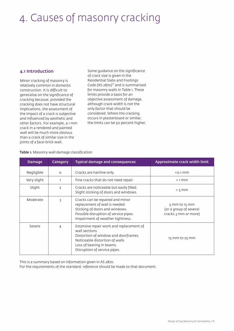
Damage Category Typical damage and consequences Approximate crack width limit
Negligible 0 Cracks are hairline only. <0.1 mm
Very slight 1 Fine cracks that do not need repair. < 1 mm
Slight 2 Cracks are noticeable but easily filled.< 5 mm
Slight sticking of doors and windows.
Moderate 3 Cracks can be repaired and minor replacement of wall is needed. 5 mm to 15 mmSticking of doors and windows. (or a group of severalPossible disruption of service pipes. cracks 3 mm or more)Impairment of weather tightness.
Severe 4 Extensive repair work and replacement of wall sections.Distortion of window and doorframes.
15 mm to 25 mmNoticeable distortion of wallsLoss of bearing in beams.Disruption of service pipes.
Table 1. Masonry wall damage classification
4.1 Introduction
Minor cracking of masonry is relatively common in domesticconstruction. It is difficult to generalise on the significance ofcracking because, provided thecracking does not have structuralimplications, the assessment ofthe impact of a crack is subjectiveand influenced by aesthetic andother factors. For example, a 1 mmcrack in a rendered and paintedwall will be much more obviousthan a crack of similar size in thejoints of a face-brick wall.
Some guidance on the significanceof crack size is given in theResidential Slabs and FootingsCode (AS 2870)12 and is summarisedfor masonry walls in Table 1. Theselimits provide a basis for an objective assessment of damage,although crack width is not theonly factor that should be considered. Where the crackingoccurs in plasterboard or similar,the limits can be 50 percent higher.
4. Causes of masonry cracking
Design of Clay Masonry for Servicability / 15
This is a summary based on information given in AS 2870.For the requirements of the standard, reference should be made to that document.
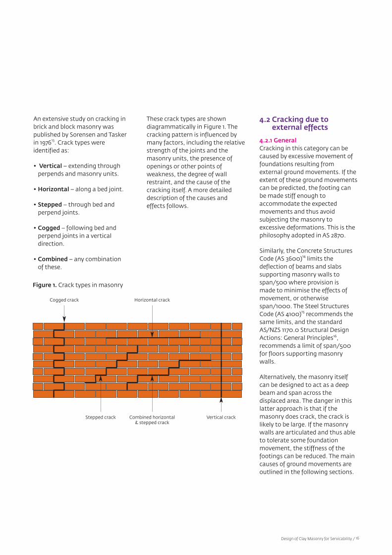
An extensive study on cracking inbrick and block masonry was published by Sorensen and Taskerin 197613. Crack types were identified as:
• Vertical – extending through perpends and masonry units.
• Horizontal – along a bed joint.
• Stepped – through bed and perpend joints.
• Cogged – following bed and perpend joints in a vertical direction.
• Combined – any combination of these.
These crack types are shown diagrammatically in Figure 1. Thecracking pattern is influenced bymany factors, including the relativestrength of the joints and themasonry units, the presence ofopenings or other points of weakness, the degree of wallrestraint, and the cause of thecracking itself. A more detaileddescription of the causes andeffects follows.
Figure 1. Crack types in masonry
4.2 Cracking due to external effects
4.2.1 GeneralCracking in this category can becaused by excessive movement offoundations resulting from external ground movements. If theextent of these ground movementscan be predicted, the footing canbe made stiff enough to accommodate the expected movements and thus avoid subjecting the masonry to excessive deformations. This is thephilosophy adopted in AS 2870.
Similarly, the Concrete StructuresCode (AS 3600)14 limits the deflection of beams and slabs supporting masonry walls tospan/500 where provision is made to minimise the effects ofmovement, or otherwisespan/1000. The Steel StructuresCode (AS 4100)15 recommends thesame limits, and the standardAS/NZS 1170.0 Structural DesignActions: General Principles16,recommends a limit of span/500for floors supporting masonrywalls.
Alternatively, the masonry itselfcan be designed to act as a deepbeam and span across the displaced area. The danger in thislatter approach is that if themasonry does crack, the crack islikely to be large. If the masonrywalls are articulated and thus ableto tolerate some foundation movement, the stiffness of thefootings can be reduced. The maincauses of ground movements areoutlined in the following sections.
Cogged crack Horizontal crack
Combined horizontal& stepped crack
Stepped crack Vertical crack
Design of Clay Masonry for Servicability / 16
with the foundation beam. If themasonry is capable of spanningacross the void created by thebeam deflections, no further distress occurs. Otherwise, thewall will crack and follow the curvature of the beam.
To eliminate the effects of soil reactivity, either the moisture variation must be stabilised, or thefoundations must be supported byunderpinning (or both). Variationsin moisture content can be reducedby the removal of offending trees,suitable drainage, and the placement of an impermeableground moisture barrier aroundthe building. If desired, a verticalbarrier can also be installed to adepth at which the soil moisturecontent is constant.
4.2.2 Moisture movement in reactive soils
Reactive (or plastic) soils compriseclays and very fine silts that swelland shrink as their moisture content increases or decreases.These movements can be quitelarge. Sorensen and Tasker13
indicate that movements of 50 mm are common, and inextreme cases movements as highas 100 mm have been recorded.The soil moisture content near thesurface is influenced by seasonalchanges in rainfall, watering ofgardens, leakage from water pipes,the presence of trees and shrubs,and solar radiation.
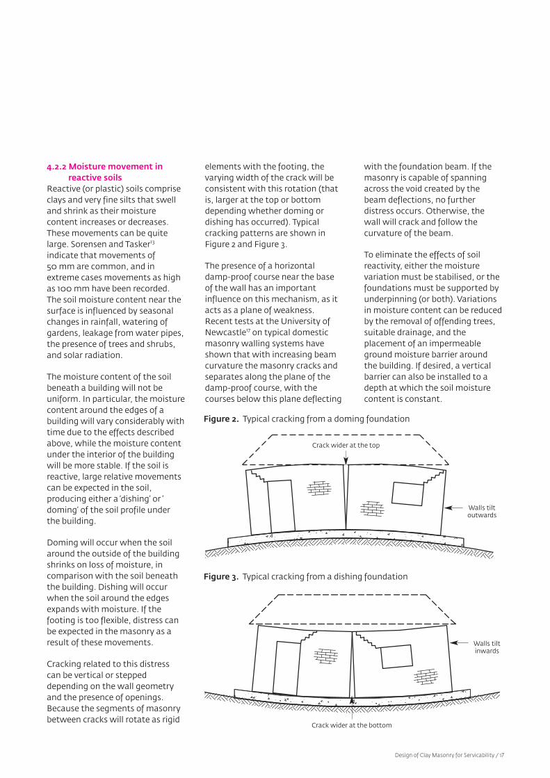
The moisture content of the soilbeneath a building will not be uniform. In particular, the moisturecontent around the edges of abuilding will vary considerably withtime due to the effects describedabove, while the moisture contentunder the interior of the buildingwill be more stable. If the soil isreactive, large relative movementscan be expected in the soil,producing either a ‘dishing’ or ‘doming’ of the soil profile underthe building.
Doming will occur when the soilaround the outside of the buildingshrinks on loss of moisture, in comparison with the soil beneaththe building. Dishing will occurwhen the soil around the edgesexpands with moisture. If the footing is too flexible, distress canbe expected in the masonry as aresult of these movements.
Cracking related to this distresscan be vertical or stepped depending on the wall geometryand the presence of openings.Because the segments of masonrybetween cracks will rotate as rigid
elements with the footing, thevarying width of the crack will beconsistent with this rotation (thatis, larger at the top or bottomdepending whether doming ordishing has occurred). Typicalcracking patterns are shown inFigure 2 and Figure 3.
The presence of a horizontal damp-proof course near the baseof the wall has an important influence on this mechanism, as itacts as a plane of weakness.Recent tests at the University ofNewcastle17 on typical domesticmasonry walling systems haveshown that with increasing beamcurvature the masonry cracks andseparates along the plane of thedamp-proof course, with thecourses below this plane deflecting
Figure 2. Typical cracking from a doming foundation
Figure 3. Typical cracking from a dishing foundation
Design of Clay Masonry for Servicability / 17
Crack wider at the top
Walls tiltoutwards
Crack wider at the bottom
Walls tiltinwards
4.2.3 Differential settlement of foundations
Differential settlement of foundations can result from a variety of causes, includingnon–uniform consolidation,construction of the building overvariable ground conditions, andlocal shear failure of part of thefoundation.
Cracks resulting from uneven settlement can take several forms,but are usually a combination ofstepped and vertical cracks. Theyare similar in many respects to themechanisms described in Section4.2.2, although the extent of thedistress will depend upon the location and nature of the differential settlement.
4.2.4 Mine subsidenceSeveral areas of Australia have, orcan expect to have, coal miningunder residential areas. The traditional method of coal removalhas been by the ‘bord and pillar’system, where initially only 30% to40% of the coal is mined, with substantial pillars of coal left tosupport the strata above. Thesepillars may then be removed lateras part of the secondary extractionprocess. Subsidence of the surfacewill occur shortly after this secondary extraction is complete.
A more recently developed alternative process is ‘retreat longwall mining’ in which the complete coal seam is removedprogressively, with the strataabove the removed section of theseam temporarily supported by amoveable propping system. Thistemporary propping systemadvances with the longwall andsurface subsidence occurs progressively18.
4.2.5 Extreme loadingAn additional potential source ofcracking in masonry housing isfrom severe loads caused by anunusual event such as a severestorm or an earthquake. Althoughthe likelihood of these events inthe life of the structure might besmall, the consequences can belarge. For example, the total costof damage from the 1989Newcastle earthquake exceeded $1 billion, with the bulk of the damage being to masonry21.
Although it might not be economical to design domesticstructures to emerge unscathedfrom this level of loading, theextent of damage can be minimised by good design,detailing and construction practices. This was illustrated bythe Newcastle experience, where a significant proportion of the damage to masonry in housingwas the result of lack of tying ofwalls, bad workmanship, poordetailing and general buildingdeterioration22.
4.3 Cracking from dimensional changes in masonry
4.3.1 GeneralMasonry will undergo changes indimensions due to variation intemperature, cycles of wetting and drying, and long-term changesassociated with moisture. If thewall detailing is such that thesedimensional changes arerestrained, then cracking canresult. The main sources of movement are briefly describedbelow. Further details are given inthe Australian Masonry Manual23.This subject is also discussed in TBAManual 2, The Properties of ClayMasonry Units.
Mine subsidence can subject houses and their footing systemsto severe movements. The groundmovements include lateral strains,settlement, curvature and tilt.A typical sequence of events as ahouse is undermined by the longwall process is for upward curvature (doming) to be followedby tilting, downward curvature(dishing), and finally a return tolevel at some distance below theoriginal ground profile, as the subsidence wave moves beyondthe dwelling.
Cracking in masonry walls resulting from mine subsidencewill often have a form similar tothat resulting from soil shrink-swell, as upward and downwardfoundation curvatures areinvolved. In this case, the influenceof tensile ground strains can alsobe significant, particularly if thefooting system is not isolated fromthe effects of these strains. Theeffects of ground strains can beminimised by keeping the footingsas shallow as possible to avoid keying into the ground, and incorporating slip layers to isolatethe footing from the ground movements19,20. In order to reducethe effects of curvature, the samephilosophy of footing designshould be adopted as that used for footings subjected to soilshrink-swell. That is, the stiffnessand strength of the footing aredesigned to accommodate theexpected curvatures so that distress to masonry walls abovethe footing system is kept withinacceptable limits12.
Design of Clay Masonry for Servicability / 18
4.3.2 Thermal changesThe thermal expansion coefficientof masonry units depends upon thematerial, the method of manufacture and the colour, and islikely to be in the range of 0.008 to0.01 mm/m/°C. Cracking fromthermal effects can result from thedifferential thermal movementscaused by temperature fluctuations between the externaland internal components of thebuilding. Temperature gradientsthrough the wall thickness mayalso produce flexural cracking.
4.3.3 Wetting and drying changesAll masonry units expand on wetting and contract on drying.The magnitude of these movements is less for clay than forconcrete and calcium silicate products. This is a reversibleprocess, which normally does notrequire consideration in commondesign of masonry.
4.3.4 Long-term permanent expansion in clay products (brick growth)
All clay products undergo a permanent long-term expansion,which for practical purposes is irreversible. The change is theresult of chemical reactionsbetween water and certain minerals in the clay. This moistureexpansion, or growth, occurs at ahigher rate initially and graduallydiminishes, with approximately50% of the total growth occurringin the first 6 months. The vastmajority of the growth will haveoccurred within a period of 15years. Growth occurs in both thehorizontal and vertical directions.
Cracking patterns from brickgrowth are usually quite distinctiveand reflect three mechanisms: differential movement betweenwalls, the restraining effects of surrounding elements, and relativemovements between sections ofthe same wall. Expansion occursboth horizontally and vertically, sothat the effects of restraint in thevertical direction can be just asimportant as restraint in the horizontal direction. The rate ofgrowth in restrained walls is lessthan in unrestrained walls such asparapets.
Cracking patterns characteristic ofbrick growth include:
• Vertical cracks or distress close tothe corners of long walls.
• Over-sailing of upper portions ofwalls over lower parts.
• Bowing and arching of parapetsor walls where expansion isrestrained.
• Distortion of window frames anddoorframes.
• Diagonal cracking adjacent toopenings, caused by differentialmovements within different sections of the wall.
Some examples of problems thatcan occur if expansion is not properly accommodated areshown in Figure 4, Figure 5 andFigure 6.
Figure 4. Cracking at offsets andcorners caused by expansion
Figure 5. Oversailing of DPCcaused by expansion
Figure 6. Failure of biscuit brickscaused by bowing and restrainedexpansion
Design of Clay Masonry for Servicability / 19
Crack at or near externalcorner or offset
Oversailingat DPC
Failure of biscuitscaused bywall rotation
In recent years, a more completeunderstanding of the mechanismof brick growth has been obtainedand AS 3700 requires that appropriate control joints beplaced in masonry to prevent possible adverse effects. A 4-houraccelerated test can be performedto predict the 15-year characteristicunrestrained expansion value forbrick units (em) and manufacturerscan provide these values whenrequired. This coefficient of expansion can range from less than0.6 mm/m for a low expansionunit, up to 1.8 mm/m in someextreme cases.
Once the coefficient of expansionis known, the spacing, size andlocation of suitable control jointscan be determined to ensure thatthe expansion of the brickwork canoccur without distress. These procedures are described in TBAManual 9, Detailing of ClayMasonry.
4.3.5 The Influence of renderCement-based render is a commonly used finish in domesticmasonry construction, and thechoice of an appropriate render isimportant if it is to perform adequately in service. Failure ofrender can occur either by loss ofbond with the backing wall (drumminess) or by cracking. It isalso possible for render shrinkageto cause distress in the masonrybacking. Whether or not failureoccurs by loss of bond or crackingwill depend upon the degree ofshrinkage of the render, the qualityof the bond, and the movement ofthe backing. Where the adhesion ofthe render is good, the restraint ofthe wall will absorb a proportion ofthe shrinkage stresses, with theremainder of the stresses dissipated by cracking. A goodreview of render properties hasbeen given by Jones24.
Rendering is a wet process with ahigh content of water to provideworkability. Drying after placement causes shrinkage in therender, which creates tensilestresses that may cause the renderto crack. The potential degree ofcracking depends upon:
• The amount of water in the mix –the higher the water content, thegreater the potential for cracking.
• The rate of water loss from themix – the faster the drying rate,the greater the likelihood ofcracking.
• The cement content of the mix –shrinkage tends to increase withhigher cement content, highertemperatures and more finelyground cements.
• The sand grading – this significantly affects the mixwater demand and the plasticproperties of the mix. The waterdemand influences the subsequent behaviour of the render, particularly its shrinkagecharacteristics.
• The standards of workmanship,the accuracy of batching of thematerials and the possible abuseof plasticising and other additives.
In addition to these shrinkageeffects, cracking of cement renderscan result from:
• Structural movements.
• Restraints provided by intersecting walls, door and window openings.
• Joints in the background material.
• Interaction with the backgroundmasonry (particularly if the render undergoes dimensionalvariation at a different rate fromthat of the masonry).
Design of Clay Masonry for Servicability / 20
4.4 Cracking from interaction with otherstructural elements
Cracking in masonry is sometimescaused by interaction with otherstructural elements rather than bythe properties of the masonryitself. In most cases, the potentialfor cracking can be eliminated byappropriate detailing.
External effects that might lead tocracking include the following:
• Shrinkage of concrete slabsConcrete slabs supported by orsupporting masonry walls willundergo drying shrinkage and, ifthey are bonded to the masonry,this will lead to undesirablestresses in the walls. This distresswill act to exacerbate the effectsof simultaneous moisture expansion of clay masonry.Cracking of this type can beavoided by incorporating a suitable slip joint between theslab and the wall. In the case of awall supported on a slab orbeam, the inclusion of a slip jointacts as a bond breaker, which willprevent unintended compositeaction that can crack the wall(see Section 5.5).
• Thermal movements of associated elementsIf steel trusses or beams areattached to masonry walls withno provision for relative move-ments, the expansion and con-traction of the members cancause distress in the masonrysimilar to that described above.
• Spreading of pitched roofsPitched roofs, particularly if tiled,have a tendency to spread andcause flexural stresses in the supporting masonry walls, whichcould lead to cracking. Struttingshould be provided to avoid thisproblem.
• Corrosion of embedded steelSteel fitments in the form of lintels, arch bars and bolts arecommonly embedded in masonry. If corrosion occurs, therusting process increases the volume of the steel, causing localdisplacement and cracking of themasonry in its vicinity. The resulting cracking is usually horizontal or stepped, and generally originates from thepoint of embedment. Cracking ofthis type can be avoided by usingsteel fitments having the appropriate corrosion resistancerating. This can be determinedfrom the provisions of AS 3700,which specifies the required corrosion resistance rating as afunction of geographical locationand proximity to the sea orsources of industrial pollution.
Design of Clay Masonry for Servicability / 21
5.1 General
If the causes and mechanisms ofcracking are understood, masonrycan be constructed to perform satisfactorily and remain essentially free of cracks for itsdesign life. Many of the problemsdescribed in Section 4 can beavoided by good design and detailing, combined with reasonable standards of workmanship.
soil reactivity and decreasing structural ductility. In most casesthe deemed-to-comply provisionsof AS 2870 can be applied.
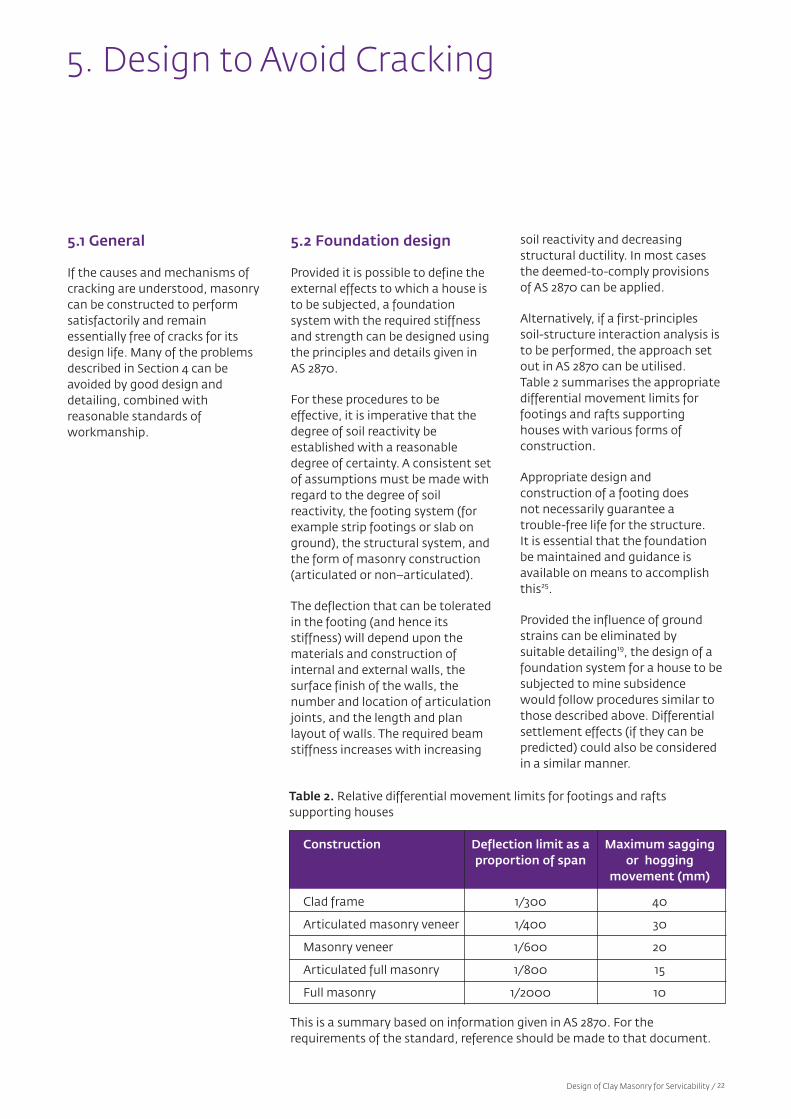
Alternatively, if a first-principlessoil-structure interaction analysis isto be performed, the approach setout in AS 2870 can be utilised.Table 2 summarises the appropriatedifferential movement limits forfootings and rafts supporting houses with various forms of construction.
Appropriate design and construction of a footing does not necessarily guarantee a trouble-free life for the structure.It is essential that the foundationbe maintained and guidance isavailable on means to accomplishthis25.
Provided the influence of groundstrains can be eliminated by suitable detailing19, the design of afoundation system for a house to besubjected to mine subsidencewould follow procedures similar tothose described above. Differentialsettlement effects (if they can bepredicted) could also be consideredin a similar manner.
5.2 Foundation design
Provided it is possible to define theexternal effects to which a house isto be subjected, a foundation system with the required stiffnessand strength can be designed usingthe principles and details given inAS 2870.
For these procedures to be effective, it is imperative that thedegree of soil reactivity be established with a reasonabledegree of certainty. A consistent setof assumptions must be made withregard to the degree of soil reactivity, the footing system (forexample strip footings or slab onground), the structural system, andthe form of masonry construction(articulated or non–articulated).
The deflection that can be toleratedin the footing (and hence its stiffness) will depend upon thematerials and construction of internal and external walls, the surface finish of the walls, the number and location of articulationjoints, and the length and plan layout of walls. The required beamstiffness increases with increasing
5. Design to Avoid Cracking
Construction Deflection limit as a Maximum sagging proportion of span or hogging
movement (mm)
Clad frame 1/300 40
Articulated masonry veneer 1/400 30
Masonry veneer 1/600 20
Articulated full masonry 1/800 15
Full masonry 1/2000 10
Table 2. Relative differential movement limits for footings and rafts supporting houses
Design of Clay Masonry for Servicability / 22
This is a summary based on information given in AS 2870. For the requirements of the standard, reference should be made to that document.

guidance on bond strength is givenin TBA Manual 10, ConstructionGuidelines for Clay Masonry26 andthe Cement and ConcreteAssociation Technical Note 6527.
Unit suction and mortar waterretentionAn effective match of the suctionproperties of the unit and thewater retention properties of themortar is essential if good bond isto be achieved. The bonding mechanism is critically dependenton the chemical and mechanicalprocesses that take place at themicroscopic scale at the interfaceof mortar and brick. In most cases,units should be laid dry and highwater demand should be balancedby adding extra water to the mortar, or by including lime in themix. In a few cases, the units mayhave to be wetted before laying. Amethyl-cellulose water-thickeningadditive can also be used to offsetthe effects of high suction units.
Mortar compositionA mortar must have adequateworkability during laying and adequate strength and durabilityin service. With the exception of proprietary thin-bed mortars,mortar should be mixed fromcement, lime and sand, with theproportion of cement increasing asthe durability requirementsincrease. Any materials used inaddition to these ingredientsshould be used with care and strictly in accordance with themanufacturer’s instructions.Overdosing with plasticising additives can seriously reduce themasonry bond strength and affectthe mortar durability. Clear evidence of this was given in theexamination of damaged buildingsafter the Newcastle earthquake22.
WorkmanshipPoor workmanship practices candrastically affect masonry bondstrength. Mortar ingredientsshould be accurately volumebatched using a box or bucket (nota shovel) or by adding a fixed volume of cement (for example a20 kg bag) to a mixer of known volume. The mixing process shouldbe controlled, particularly the useof additives. Bonding surfacesshould be clean, both bed and perpend joints should be completely filled, and freshly laidunits should not be disturbed afterinitial placement.
Tying and support of masonryMasonry is a brittle material withrelatively low tensile strength. Itmust therefore be adequately supported to ensure that anyapplied loads can be resisted satisfactorily and that crackingdoes not result. Masonry veneerwalls, which are non–structural,must be adequately supported byties that will transfer the loads tothe supporting structure. It isessential that these ties have adequate strength and stiffness,and be spaced and installed correctly. Ties for domestic construction are usually either lightor medium duty as categorised byAS/NZS 2699.1. Deemed–to–complydetails for tie placement are givenin AS 3700 and further guidance isgiven in TBA Manual 4, Design ofClay Masonry for Wind andEarthquake28. The durabilityrequirements for wall ties are particularly important if the structure is located near the coastor industry, because ties with inadequate protection can bedestroyed by corrosion. Design for durability is discussed in Section 7.4.
5.3 Masonry quality
5.3.1 GeneralCracking results from tensileand/or shear stresses induced inthe masonry. The causes of cracking have been described inSection 4. The ability of the masonry to resist cracking under agiven set of circumstances isdirectly related to its tensilestrength. For typical clay masonry,the tensile bond strength of thejoints is significantly lower thanthe compressive strength of themasonry units. The achievement ofgood bond between the mortarand the masonry units is thereforeessential, if cracking is to be minimised.
5.3.2 Bond strengthThe bond strength between mortar and masonry units is influenced by many factors, ofwhich the main ones are:
• Initial rate of absorption (suction) of the masonry units.
• Water retention properties of themortar.
• Composition of the mortar andthe presence of additives.
• Standards of workmanship.
Values of bond strength can varywidely because of these effects(particularly workmanship) butcharacteristic flexural tensile bondstrengths will usually lie in therange of 0.2 MPa to 0.5 MPa.However, if workmanship is poor,and the mix is overdosed withplasticiser, there is no guaranteethat this level of bond will beachieved. The various factors arediscussed in what follows; further
Design of Clay Masonry for Servicability / 23
5.4 Masonry detailing
5.4.1 GeneralApart from effective tying and support, masonry must also bedetailed correctly if cracking is tobe avoided. Provided the masonryis of sufficient quality, masonrycracking can be avoided by theprovision of various forms of control joints and adequate detailing. The nature, location andspacing of the joints will dependupon the movements for whichthey are inserted, and in manycases can compensate for severaltypes of movement at once. Forexample, articulation joints inserted to cater for foundationmovements will also function asexpansion joints for clay masonry.This section gives a brief overviewof suitable jointing and detailingtechniques. Further guidance canbe found in TBA Manual 9,Detailing of Clay Masonry.
5.4.2 Locations of articulation joints
Articulation joints are used in conjunction with a foundation tocontrol the effects of ground movements. The joints articulatethe masonry components of thebuilding into separate elements,which undergo rigid body rotations as the footing deflects,without causing distress in themasonry. The more flexible thefooting, or the more susceptiblethe surface finish is to cracking,the closer the required spacing ofthe joints will be. Articulation notonly limits cracking of walls, butalso avoids the potential jammingof windows and doors caused byfoundation movement.
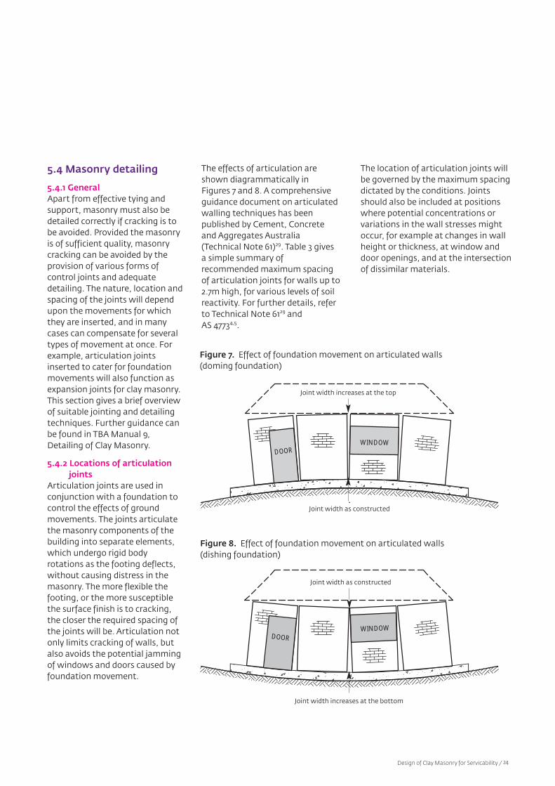
The effects of articulation areshown diagrammatically in Figures 7 and 8. A comprehensive guidance document on articulatedwalling techniques has been published by Cement, Concreteand Aggregates Australia(Technical Note 61)29. Table 3 givesa simple summary of recommended maximum spacingof articulation joints for walls up to2.7m high, for various levels of soilreactivity. For further details, referto Technical Note 6129 and AS 47734,5.
The location of articulation joints willbe governed by the maximum spacingdictated by the conditions. Jointsshould also be included at positionswhere potential concentrations or variations in the wall stresses mightoccur, for example at changes in wallheight or thickness, at window anddoor openings, and at the intersectionof dissimilar materials.
Figure 7. Effect of foundation movement on articulated walls (doming foundation)
Figure 8. Effect of foundation movement on articulated walls(dishing foundation)
DOORWINDOW
DOORWINDOW
Design of Clay Masonry for Servicability / 24
Joint width increases at the top
Joint width increases at the bottom
Joint width as constructed
Joint width as constructed

Site class Wall construction Joint spacing (m)
A and S Any not required
M and H Masonry veneer 7.0
Full masonry
• Sheeted and/or faced finish 6.5
• Rendered or painted finish 5.5
E Masonry veneer 6.0
(deflection ratio 1/400)
Full masonry
• Sheeted and/or faced finish 5.5
(deflection ratio 1/600)
• Rendered or painted finish 5.0
(deflection ratio 1/800)
This is a summary covering simple cases. For more information,
refer to TN 61 and AS 4773.
Notes:
1.Site classes are as follows:
A = Most sand and rock sites
S = Most silt and some clay sites
M = Moderately reactive clay sites
H = Highly reactive clay sites
E = Extremely reactive clay sites
2.For E class sites, a footing design prepared by an engineer is recommended. Joint spacing will depend on the deflection ratio adopted.
Table 3. Recommended maximum spacing of articulation joints in wallsup to 2.7m high
5.4.3 Detailing of articulation joints
For obvious reasons, articulationjoints must be capable of expanding or contracting to caterfor the rigid body displacements ofthe walls as they rotate with thefootings. As wall rotation isinvolved, the joint thickness willvary with height and open or closeat the top or bottom of the walldepending on whether the footingis subjected to ‘doming’ or ‘dishing’curvature (see Figure 7 and Figure8). The joint is usually packed witha compressible filler to provide abacking for the flexible sealantcompound applied to the surface ofthe joint. Alternatively, a circularpolyethylene backer-rod can beused as backing for the sealant. It isextremely important that the jointbe free of mortar droppings orother obstructions that will impedethe closing of the joint. Typicalmethods of sealing joints areshown in Figure 9.
Figure 9. Typical methods of sealing articulation and controljoints
Design of Clay Masonry for Servicability / 25
Closed cell polyethylenerod backing
Caulkingcompound
Impregnatedfoam seal
Articulation joints might also berequired for internal walls. With good planning, the joints can beincorporated at full height openingssuch as doorways. Where joints areunavoidable, for example in long
unbroken lengths of wall, theyshould be of the same form asjoints in the external walls.More details of these aspects are discussed in Technical Note 6129.
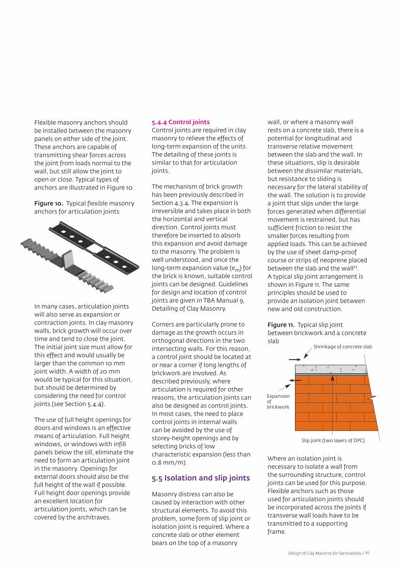
Flexible masonry anchors shouldbe installed between the masonrypanels on either side of the joint.These anchors are capable oftransmitting shear forces acrossthe joint from loads normal to thewall, but still allow the joint toopen or close. Typical types ofanchors are illustrated in Figure 10.
Figure 10. Typical flexible masonryanchors for articulation joints
In many cases, articulation jointswill also serve as expansion or contraction joints. In clay masonrywalls, brick growth will occur overtime and tend to close the joint.The initial joint size must allow forthis effect and would usually belarger than the common 10 mmjoint width. A width of 20 mmwould be typical for this situation,but should be determined by considering the need for controljoints (see Section 5.4.4).
The use of full height openings fordoors and windows is an effectivemeans of articulation. Full heightwindows, or windows with infillpanels below the sill, eliminate theneed to form an articulation jointin the masonry. Openings forexternal doors should also be thefull height of the wall if possible.Full height door openings providean excellent location for articulation joints, which can becovered by the architraves.
5.4.4 Control jointsControl joints are required in claymasonry to relieve the effects oflong-term expansion of the units.The detailing of these joints is similar to that for articulationjoints.
The mechanism of brick growthhas been previously described inSection 4.3.4. The expansion is irreversible and takes place in boththe horizontal and vertical direction. Control joints musttherefore be inserted to absorbthis expansion and avoid damageto the masonry. The problem iswell understood, and once thelong-term expansion value (em) forthe brick is known, suitable controljoints can be designed. Guidelinesfor design and location of controljoints are given in TBA Manual 9,Detailing of Clay Masonry.
Corners are particularly prone todamage as the growth occurs inorthogonal directions in the twointersecting walls. For this reason,a control joint should be located ator near a corner if long lengths ofbrickwork are involved. Asdescribed previously, where articulation is required for otherreasons, the articulation joints canalso be designed as control joints.In most cases, the need to placecontrol joints in internal walls can be avoided by the use of storey-height openings and byselecting bricks of low characteristic expansion (less than0.8 mm/m).
5.5 Isolation and slip joints
Masonry distress can also becaused by interaction with otherstructural elements. To avoid thisproblem, some form of slip joint orisolation joint is required. Where aconcrete slab or other elementbears on the top of a masonry
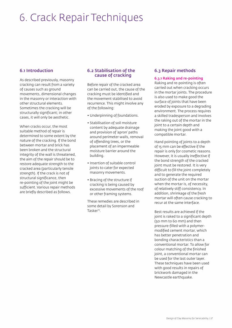
wall, or where a masonry wallrests on a concrete slab, there is apotential for longitudinal andtransverse relative movementbetween the slab and the wall. Inthese situations, slip is desirablebetween the dissimilar materials,but resistance to sliding is necessary for the lateral stability ofthe wall. The solution is to providea joint that slips under the largeforces generated when differentialmovement is restrained, but hassufficient friction to resist thesmaller forces resulting fromapplied loads. This can be achievedby the use of sheet damp-proofcourse or strips of neoprene placedbetween the slab and the wall23.A typical slip joint arrangement isshown in Figure 11. The same principles should be used to provide an isolation joint betweennew and old construction.
Figure 11. Typical slip jointbetween brickwork and a concreteslab
Where an isolation joint is necessary to isolate a wall fromthe surrounding structure, controljoints can be used for this purpose.Flexible anchors such as thoseused for articulation joints shouldbe incorporated across the joints iftransverse wall loads have to betransmitted to a supportingframe.
Design of Clay Masonry for Servicability / 26
Shrinkage of concrete slab
Slip joint (two layers of DPC)
Expansionof brickwork
6.1 Introduction
As described previously, masonrycracking can result from a varietyof causes such as ground movements, dimensional changesin the masonry or interaction withother structural elements.Sometimes the cracking will bestructurally significant; in othercases, it will only be aesthetic.
When cracks occur, the most suitable method of repair is determined to some extent by thenature of the cracking. If the bondbetween mortar and brick hasbeen broken and the structuralintegrity of the wall is threatened,the aim of the repair should be torestore adequate strength to thecracked area (particularly tensilestrength). If the crack is not ofstructural significance, then re-pointing of the joint might besufficient. Various repair methodsare briefly described as follows.
6.2 Stabilisation of thecause of cracking
Before repair of the cracked areacan be carried out, the cause of thecracking must be identified andthe movement stabilised to avoidrecurrence. This might involve anyof the following:
• Underpinning of foundations.
• Stabilisation of soil moisture content by adequate drainageand provision of ‘apron’ pathsaround perimeter walls, removalof offending trees, or the placement of an impermeablemoisture barrier around thebuilding.
• Insertion of suitable controljoints to cater for expectedmasonry movements.
• Bracing of the structure if cracking is being caused byexcessive movements of the roofor other framing systems.
These remedies are described insome detail by Sorenson andTasker13.
6.3 Repair methods
6.3.1 Raking and re-pointingRaking and re-pointing is oftencarried out when cracking occursin the mortar joints. The procedureis also used to make good the surface of joints that have beeneroded by exposure to a degradingenvironment. The process requiresa skilled tradesperson and involvesthe raking out of the mortar in thejoint to a certain depth and making the joint good with a compatible mortar.
Hand pointing of joints to a depthof 15 mm can be effective if therepair is only for cosmetic reasons.However, it is usually ineffective ifthe bond strength of the crackedjoint must be restored. It is verydifficult to fill the joint completelyand to generate the required suction of the unit on the mortarwhen the mortar is, of necessity,of relatively stiff consistency. In addition, shrinkage of the freshmortar will often cause cracking torecur at the same interface.
Best results are achieved if thejoint is raked to a significant depth(50 mm to 60 mm) and then pressure-filled with a polymer-modified cement mortar, whichhas better penetration and bonding characteristics than aconventional mortar. To allow forcolour matching of the finishedjoint, a conventional mortar canbe used for the last outer layer.These techniques have been usedwith good results in repairs ofbrickwork damaged in theNewcastle earthquake.
6. Crack Repair Techniques
Design of Clay Masonry for Servicability / 27

6.3.2 Reconstruction of selected areas
For obvious reasons demolitionand re–building of a damaged section of masonry should restoreits structural integrity. However,problems are often encountered atthe junction of new and existingwork unless a control joint can beused to isolate new from old. Inmany instances, the new masonryis toothed into the existing workto create a key. In these cases,similar problems to thosedescribed in raking and re-pointingcan be encountered, as bond hasto be established at the junction ofthe new and old masonry.
Bond can usually be achieved inthe bed joints below the bricks inthe toothed area. However, at thevertical junction of the last perpend joints and the existingconstruction, and for the top bedjoint of the new constructionbelow the existing masonry above,bond depends upon the effectiveplacement of the mortar for thefull joint depth and thickness.Unless polymer-modified mortarsare used, this is very difficult toachieve.
As for the case of re-pointing,mortar shrinkage can also createsubsequent cracking at the interface of new and old. For effective repair work, it is therefore important that skilledtradespeople and the correctmaterials are used.
6.3.3 Epoxy injectionThis method has been used effectively in repairs to damagedmasonry housing in Newcastle following the 1989 earthquake.However, it is a skilled operationrequiring specialist equipment andpersonnel, and is usually moreexpensive than the more conventional repair methodsdescribed above. Despite the extracost, full penetration of cracks andeffective bond can be achieved.The technique also has the advantage of being applicable tocracks in the masonry units as wellas the mortar joints.
If epoxy repair techniques are to be used, it is important that thecorrect epoxy mix is chosen. Theepoxy must have adequate penetration and wetting characteristics, have sufficientbond capacity, and be of compatible stiffness to the material being repaired. The last of these requirements is to avoidthe creation of local regions ofhigh stiffness, which might createlocal concentrations of stressunder subsequent movementsfrom thermal and other causes.Mixes with the appropriate characteristics are available.
Design of Clay Masonry for Servicability / 28
7. Design for Durability
7.1 General
For a structure to remain serviceable, it must be durablethroughout its life, assuming a reasonable level of building maintenance is carried out. Themain causes of durability failureare corrosion of embedded steelitems and the effects of crystallinesalts in the masonry. Salts can bedrawn in from the atmosphere,drawn up from the ground, or bepresent in building materials suchas the sand used to mix the mortar.
To ensure adequate serviceability,AS 3700 requires that membersand structures have the necessarydurability to withstand the expected wear and deteriorationthroughout the intended life without the need for excessivemaintenance. The required durability depends on the exposureenvironment and importance ofthe structure. A typical design lifeis 50 years.
While AS 3700 is not explicit aboutthe intended life or the importanceof the structure, it gives extensivedeemed-to-satisfy solutions foreach of the wall components andfor a range of environmental conditions. In order to satisfy therequirements, each componentmust be graded in accordance withits respective durability.
The exposure environmentsreferred to in Table 5.1 of AS 3700are described in more detail in theinformative Appendix E of thestandard. They are as follows:
• Mild – typically inland, not in thetropics and away from industrialareas.
• Exterior – exposed walls in non-marine locations. Both the exterior leaf of a cavity wall andthe cavity space are regarded asbeing in an exterior environment.
• Interior – all internal walls of abuilding, including the interiorleaf of a cavity wall that isexposed on the exterior.
• Marine – between 100 metresand 1 kilometre from a non-surfcoast and between 1 kilometreand 10 kilometres from a surfcoast. The coast is defined as themean high-water mark.
• Severe marine – up to 100metres from a non-surf coast andup to 1 kilometre from a surfcoast. As before, the coast isdefined as the mean high-watermark.
It is important to realise that theclassification of exposure environments should be applied toindividual elements or members.It cannot be argued, for example,that the cavity space of an externalcavity wall is in an interior environment. An external cavitywall of a building is a member inan above-ground exterior environment and the cavity spacetherefore has this classification.
The design of each of the components of masonry to provide the necessary durability is discussed in the following.
Design of Clay Masonry for Servicability / 29
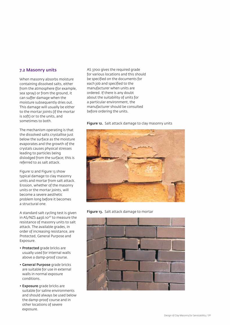
7.2 Masonry units
When masonry absorbs moisturecontaining dissolved salts, eitherfrom the atmosphere (for example,sea spray) or from the ground, itcan suffer damage when the moisture subsequently dries out.This damage will usually be eitherto the mortar joints (if the mortaris soft) or to the units, and sometimes to both.
The mechanism operating is thatthe dissolved salts crystallise justbelow the surface as the moistureevaporates and the growth of thecrystals causes physical stressesleading to particles being dislodged from the surface; this isreferred to as salt attack.
Figure 12 and Figure 13 show typical damage to clay masonryunits and mortar from salt attack.Erosion, whether of the masonryunits or the mortar joints, willbecome a severe aesthetic problem long before it becomes a structural one.
A standard salt cycling test is givenin AS/NZS 4456.1030 to measure theresistance of masonry units to saltattack. The available grades, inorder of increasing resistance, areProtected, General Purpose andExposure.
• Protected grade bricks are usually used for internal wallsabove a damp-proof course.
• General Purpose grade bricksare suitable for use in externalwalls in normal exposure conditions.
• Exposure grade bricks are suitable for saline environmentsand should always be used belowthe damp-proof course and inother locations of severe exposure.
Figure 12. Salt attack damage to clay masonry units
Figure 13. Salt attack damage to mortar
AS 3700 gives the required grade for various locations and this shouldbe specified on the documents for each job and specified to the manufacturer when units areordered. If there is any doubt about the suitability of units for a particular environment, the manufacturer should be consultedbefore ordering the units.
Design of Clay Masonry for Servicability / 30
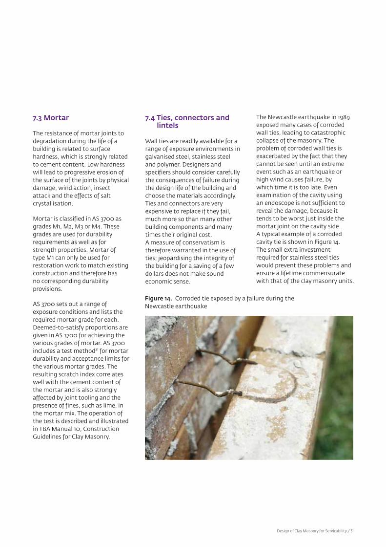
7.3 Mortar
The resistance of mortar joints todegradation during the life of abuilding is related to surface hardness, which is strongly relatedto cement content. Low hardnesswill lead to progressive erosion ofthe surface of the joints by physicaldamage, wind action, insect attack and the effects of salt crystallisation.
Mortar is classified in AS 3700 asgrades M1, M2, M3 or M4. Thesegrades are used for durabilityrequirements as well as forstrength properties. Mortar of type M1 can only be used forrestoration work to match existingconstruction and therefore has no corresponding durability provisions.
AS 3700 sets out a range of exposure conditions and lists therequired mortar grade for each.Deemed-to-satisfy proportions aregiven in AS 3700 for achieving thevarious grades of mortar. AS 3700includes a test method31 for mortardurability and acceptance limits forthe various mortar grades. Theresulting scratch index correlateswell with the cement content ofthe mortar and is also stronglyaffected by joint tooling and thepresence of fines, such as lime, inthe mortar mix. The operation ofthe test is described and illustratedin TBA Manual 10, ConstructionGuidelines for Clay Masonry.
7.4 Ties, connectors andlintels
Wall ties are readily available for arange of exposure environments ingalvanised steel, stainless steeland polymer. Designers and specifiers should consider carefullythe consequences of failure duringthe design life of the building andchoose the materials accordingly.Ties and connectors are veryexpensive to replace if they fail,much more so than many otherbuilding components and manytimes their original cost.A measure of conservatism istherefore warranted in the use ofties; jeopardising the integrity ofthe building for a saving of a fewdollars does not make sound economic sense.
Figure 14. Corroded tie exposed by a failure during theNewcastle earthquake
The Newcastle earthquake in 1989exposed many cases of corrodedwall ties, leading to catastrophiccollapse of the masonry. The problem of corroded wall ties isexacerbated by the fact that theycannot be seen until an extremeevent such as an earthquake orhigh wind causes failure, by which time it is too late. Evenexamination of the cavity using an endoscope is not sufficient toreveal the damage, because it tends to be worst just inside themortar joint on the cavity side.A typical example of a corroded cavity tie is shown in Figure 14.The small extra investment required for stainless steel tieswould prevent these problems andensure a lifetime commensuratewith that of the clay masonry units.
Design of Clay Masonry for Servicability / 31
Wall ties and other built-in components such as connectorsfor control joints, connectors forattachment of masonry to buildingframes, and lintels, are required tohave a rating for durability (calleda durability class) relevant to theexposure conditions. The durabilityratings required by AS 3700 are R0,R1, R2, R3, R4 and R5. AS 3700 setsout a series of locations for masonry elements, related tothese environments, and gives arequired durability rating for each,using the symbols R0 to R5.
AS/NZS 2699 includes test procedures for establishing durability ratings for wall ties10,connectors and accessories32 andlintels33. However, these tests arenot intended for routine use onindividual projects. AS/NZS 2699 isa manufacturing standard and it isthe responsibility of manufacturersto establish ratings for their products. This should be done atthe time of product development,before bringing the product tomarket. To ease the burden onmanufacturers, the standard contains deemed-to-satisfy durability ratings for steel tiesmanufactured from sheet andwire. These provisions will be reliedupon in most cases and provide asimple means of satisfying therequirements of AS 3700.
Durability class R5 is intended forcritical applications in special situations such as tidal and splashzones or areas of heavy chemicalpollution. No test criteria ordeemed-to-satisfy solutions aregiven for the R5 rating.
Wall ties manufactured from non-metallic materials such aspolymers are also available andcan be used provided they havebeen shown to satisfy the exposure conditions set out inAS/NZS 2699.1 corresponding tothe requirements of AS 3700.
AS/NZS 2699.1 requires all ties to be marked on the packaging andon individual ties with the durability rating. For the packaging, this must consist of areference to AS/NZS 2699.1 and arating (R0 to R5). For individualties, they should be stamped with 0 to 4, indicating the corresponding rating R0 to R4,or colour coded as follows:
• R0 and R1 green
• R2 yellow
• R3 red
• R4 white or blue
Wall ties without the appropriatemarkings should be assumed notto comply with the standard andshould not be used.
7.5 Reinforcement
Reinforcing bars can be providedwith a corrosion-resistant coatingto achieve the required durabilityrating, but will usually rely on aminimum grout cover to ensure anacceptable level of resistance.The required covers, which do notinclude the face shell thickness ofthe unit, are given in AS 3700. Forthis purpose, the grout is requiredto have at least 300 kg/m3 cementcontent.
Reinforcement embedded in mortar joints must have corrosionprotection to achieve a durabilityrating of R0 to R5, as for ties andaccessories, plus a minimum coverof 15 mm of mortar to the outsideof the masonry. The requirementfor separate protection to providethe durability rating is in recognition of the fact that mortardoes not give the same degree ofprotection to the steel as doescement-rich grout. Similarly, inprestressed masonry, unbondedtendons must be protected to givethe required durability rating.No deemed-to-satisfy solutions are provided in AS 3700 for reinforcement in mortar joints orunbonded tendons. The designermust therefore assess the durability rating for each particularmaterial.
Design of Clay Masonry for Servicability / 32

Where –
H = Clear height of the member(in metres)
tr = Minimum thickness of themember (for a cavity wall =two-thirds the sum of thethicknesses of the two leaves)(in metres)
kt = thickness coefficient forengaged piers (tabulated inAS 3700)
Cv = Robustness coefficient forvertical span (tabulated in AS3700)
Ch = Robustness coefficient forhorizontal span (tabulated inAS 3700)
Lr = Clear length of the wall, orlength to the centre of anopening (in metres)
The stiffening action of engagedpiers is only taken into account forwalls in pure vertical spanning.Even then, the piers must be quitesubstantial before they are effective. Note that both leaves ofa cavity wall are considered to acttogether for the purposes ofrobustness, unlike for compressivestrength design.
These design rules can beexpressed as limiting heights andlengths for a given wall thickness.These are shown as charts for various wall configurations inSection 8.2.
The equations for walls with sidesupport (leading to two-way bending or panel action) result in a smooth curve, unlike the caseswith only top and bottom support,and this recognises the importance and effect of having at least one vertical support to stabilise the wall.
8. Robustness
8.1 Design principles
AS 3700 requires masonry members and their connections to have an adequate degree ofrobustness, regardless of the levelof load to which they are subjected, but it does not definewhat is meant by robustness.
The principle is that even if a wallis designed to satisfy all the prescribed loads, it should not beso slender as to fail under someunintended or accidental load andit should have adequate stiffness.If the wall is capable of withstanding a minimum level oflateral load of about 0.5 kPa, it willusually have the necessary robustness. Since calculations forlateral load are quite complex,deemed-to-satisfy rules are givenin AS 3700, based on simplifiedslenderness ratios.
It is important to realise that allwalls, irrespective of their level of loading (and including non-loadbearing walls) must satisfy the robustness requirements of AS 3700.
The rules take a simplifiedapproach to restraint conditions,by considering only three commoncases:
• A wall with a free top
• A wall or pier with any loading orsupport other than a concreteslab
• A wall carrying a concrete slab
Unreinforced isolated piers aremore vulnerable than walls andthe limiting slenderness ratio foran isolated pier is therefore halfthe value for a similar wall. A pierhas both length and width lessthan one-fifth of the height.
Robustness is controlled by a set of equations, which give limits onheight for one-way and two-wayspanning members as follows:
1. For isolated piers –
2. For walls spanning vertically –
3. For walls with at least one vertical edge laterally supportedand
= No limit
4. For walls with at least one vertical edge laterally supportedand
Design of Clay Masonry for Servicability / 33
H Cvtr
<
H Cvkttr
<
<
Lr Chtr
H tr
<
Lr Chtr
>
H Cv +tr
< ChLr - Chtr
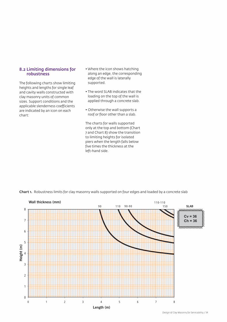
8.2 Limiting dimensions forrobustness
The following charts show limitingheights and lengths for single leafand cavity walls constructed withclay masonry units of commonsizes. Support conditions and theapplicable slenderness coefficientsare indicated by an icon on eachchart:
• Where the icon shows hatchingalong an edge, the correspondingedge of the wall is laterally supported.
• The word SLAB indicates that theloading on the top of the wall isapplied through a concrete slab.
• Otherwise the wall supports aroof or floor other than a slab.
The charts for walls supportedonly at the top and bottom (Chart7 and Chart 8) show the transitionto limiting heights for isolatedpiers when the length falls belowfive times the thickness at the left-hand side.
Chart 1. Robustness limits for clay masonry walls supported on four edges and loaded by a concrete slab
8
7
6
5
4
3
2
1
00 1 2 3 4 5 6 7 8
Length (m)
Hei
ght
(m)
90Wall thickness (mm)
110 15090-90110-110
Cv = 36Ch = 36
SLAB
Design of Clay Masonry for Servicability / 34
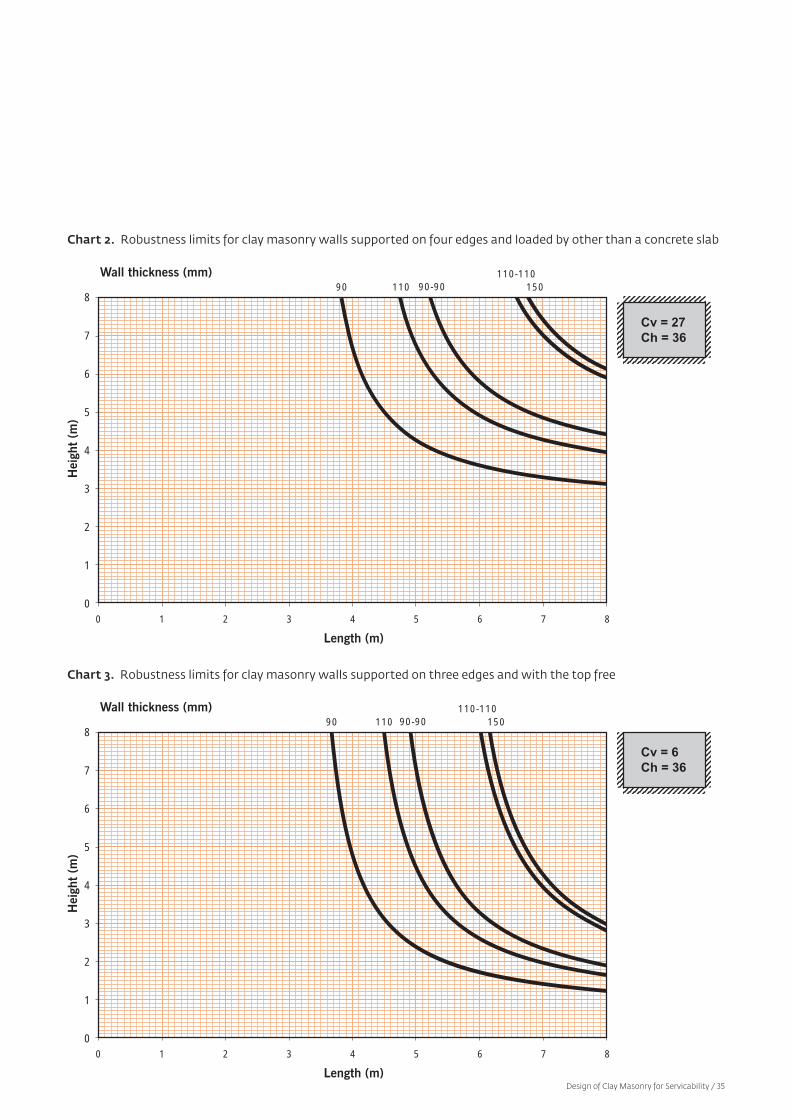
Chart 2. Robustness limits for clay masonry walls supported on four edges and loaded by other than a concrete slab
Chart 3. Robustness limits for clay masonry walls supported on three edges and with the top free
8
7
6
5
4
3
2
1
00 1 2 3 4 5 6 7 8
Length (m)
Hei
ght
(m)
Cv = 27Ch = 36
90Wall thickness (mm)
110 15090-90110-110
8
7
6
5
4
3
2
1
00 1 2 3 4 5 6 7 8
Length (m)
Hei
ght
(m)
Cv = 6Ch = 36
90Wall thickness (mm)
110 15090-90110-110
Design of Clay Masonry for Servicability / 35
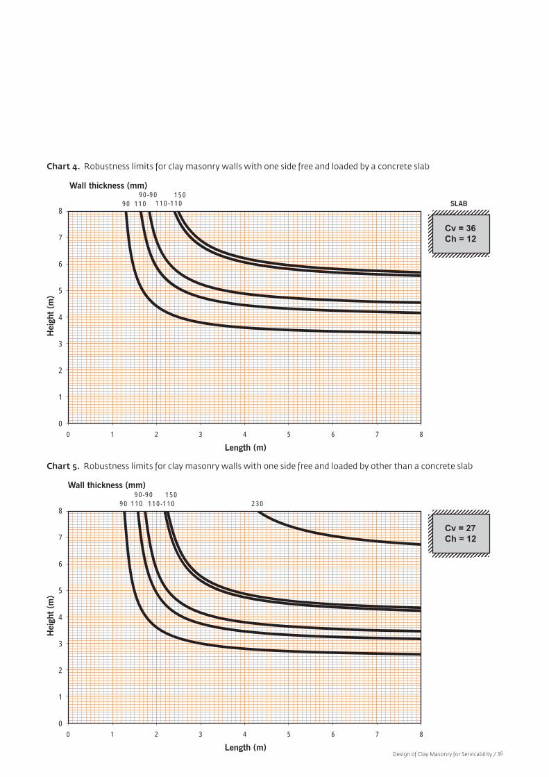
Chart 4. Robustness limits for clay masonry walls with one side free and loaded by a concrete slab
Chart 5. Robustness limits for clay masonry walls with one side free and loaded by other than a concrete slab
8
7
6
5
4
3
2
1
00 1 2 3 4 5 6 7 8
Length (m)
Hei
ght
(m)
90
Wall thickness (mm)
SLAB11015090-90
110-110
Cv = 36Ch = 12
8
7
6
5
4
3
2
1
00 1 2 3 4 5 6 7 8
Length (m)
Hei
ght
(m)
90
Wall thickness (mm)
11015090-90
110-110 230
Cv = 27Ch = 12
Design of Clay Masonry for Servicability / 36

Chart 6. Robustness limits for clay masonry walls supported on two edges
Chart 7. Robustness limits for clay masonry walls supported at top and bottom and loaded by a concrete slab
8
7
6
5
4
3
2
1
00 1 2 3 4 5 6 7 8
Length (m)
Hei
ght
(m)
Cv = 6Ch = 12
90
Wall thickness (mm)
11015090-90
110-110 230
8
7
6
5
4
3
2
1
00 1 2 3 4 5 6 7 8
Length (m)
Hei
ght
(m)
90
230Wall Thickness (mm)
110
150
90-90
110-110
Cv = 36
SLAB
Design of Clay Masonry for Servicability / 37
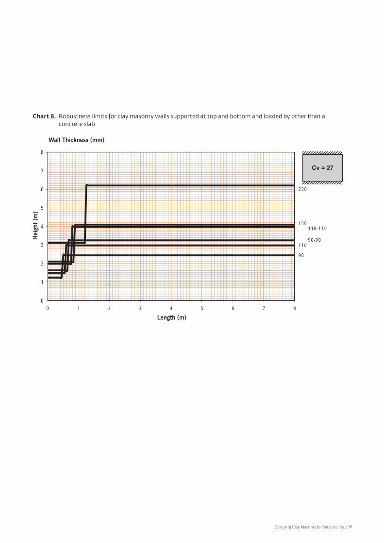
Chart 8. Robustness limits for clay masonry walls supported at top and bottom and loaded by other than a concrete slab
8
7
6
5
4
3
2
1
00 1 2 3 4 5 6 7 8
Length (m)
Hei
ght
(m)
90
230
Wall Thickness (mm)
110
150
90-90
110-110
Cv = 27
Design of Clay Masonry for Servicability / 38
9. References
1 Building Code of Australia Volume 1:Class 2 to Class 9 Buildings andVolume 2: Class 1 and Class 10Buildings (Housing Provisions),Australian Building Codes Board,Canberra, 2007.
2 AS3700:2001, Masonry Structures,Standards Australia, Sydney 2001.
3 AS 3700 Supplement 1, MasonryStructures – Commentary, StandardsAustralia, Sydney, 2004.
4 AS 4773.1, Masonry in SmallBuildings – Design), StandardsAustralia, Sydney, (publicationpending).
5 AS 4773.2, Masonry in SmallBuildings – Construction, StandardsAustralia, Sydney, (publicationpending).
6 Manual 2, The Properties of ClayMasonry Units, Clay Brick andPaver Institute, Sydney, 2001.
7 AS/NZS 4455 Part 1:2008, MasonryUnits, Pavers, Flags and SegmentalRetaining Wall Units – Part 1:Masonry Units, StandardsAustralia, Sydney, 2008.
8 Manual 9, Detailing of ClayMasonry, Think Brick Australia,Sydney, 2008.
9 AS/NZS 1170.1:2002, StructuralDesign Actions Part 1: Permanent,Imposed and Other Actions,Standards Australia, Sydney,2002.
10 AS/NZS 2699.1:2000, Built-inComponents for MasonryConstruction, Part 1: Wall Ties,Standards Australia, Sydney,2000.
21 Melchers, R.E. & Page, A.W.The Newcastle Earthquake,Proceedings – Civil EngineeringStructures and Building, V94,May 1992, pp.143–156.
22 Page, A.W. The Design, Detailingand Construction of Masonry –The Lessons From the NewcastleEarthquake, Australian CivilEngineering Transactions, TheInstitution of EngineersAustralia, VCE34, N4,December 1992, pp.343–353.
23 Baker, L.R., Lawrence, S.J. &Page, A.W. Australian MasonryManual, NSW Public WorksDepartment and Association ofConsulting StructuralEngineers of NSW, Sydney,1991.
24 Jones, I. Render – TheTechnologists Viewpoint,External Rendered SurfacesSymposium, Concrete Instituteof Australia, Melbourne, March1979.
25 Guide to Home Owners onFoundation Maintenance andFooting Performance,Information Sheet 10-91, CSIRODivision of BuildingConstruction and Engineering,Melbourne, 1995.
26 Manual 10, ConstructionGuidelines for Clay Masonry,Think Brick Australia, Sydney,February 2008.
27 Bond Strength in MasonryConstruction, Technical Note 65,Cement and ConcreteAssociation of Australia,Sydney, May 2001.
11 AS/NZS 2904–1995, Damp-proofCourses and Flashings, StandardsAustralia, Sydney, 1995.
12 AS 2870-1996, Residential Slabs andFootings – Construction, StandardsAustralia, Sydney, 1996.
13 Sorenson, C.P. & Tasker, H.E.Cracking in Brick and Block Masonry,Technical Study 43, ExperimentalBuilding Station, Sydney, 1976.
14 AS 3600:2001, Concrete Structures,Standards Australia, Sydney,2001.
15. AS 4100–1998, Steel Structures,Standards Australia, Sydney,1998.
16 AS/NZS 1170.0–2002, StructuralDesign Actions Part 0: GeneralPrinciples, Standards Australia,Sydney, 2002.
17 Page, A.W.; Kleeman, P.W. &Bryant, I. Development ofServiceability Criteria for MasonryStructures - a Preliminary Report,Proceedings of the 6th NorthAmerican Masonry Conference,Philadelphia, June 1993.
18 NSW Coal Association MineSubsidence – A CommunityInformation Booklet, Departmentof Minerals and Energy and theMine Subsidence Board, 1989.
19 Hanson, R.G. Designing forSubsidence, Mine SubsidenceBoard Annual Review, 1988–1989.
20 Holla, L. The Response of DomesticStructures to Ground MovementsCaused by Mining Subsidence,National Structural EngineeringConference, The Institution ofEngineers, 1987, pp.472–477.
Design of Clay Masonry for Servicability / 39
28 Manual 4, Design of Clay Masonryfor Wind and Earthquake, ClayBrick and Paver Institute,Sydney, March 1999.
29 Articulated Walling, TechnicalNote 61, Cement, Concrete andAggregates Australia, Sydney,2008.
30 AS/NZS 4456.10:2003, MasonryUnits, Segmental Pavers and Flags –Methods of Test, Method 10:Determining Resistance to SaltAttack, Standards Australia,Sydney, 2003.
31 Lawrence, S.J., & Samarasinghe,W. A New Method for Assessing theService Life of Masonry Mortars,Rehabilitation of Structures:Proceedings of the 2ndInternational RILEM/CSIRO/ACRA Conference, Melbourne,September 1998: pp.481-488.
32 AS/NZS 2699.2:2000,Built-in Components for MasonryConstruction, Part 2: Connectorsand Accessories, StandardsAustralia, Sydney, 2000.
33 AS/NZS 2699.3:2000,Built-in Components for MasonryConstruction, Part 3: Lintels andShelf Angles (DurabilityRequirements), StandardsAustralia, Sydney, 2000.
Design of Clay Masonry for Servicability / 40