Embed Size (px)
Citation preview

Managing Stormwater for Urban Sustainability Using Trees and Structural Soils
A new space-saving infiltration BMP that mitigates runoff from paved areas
Susan Downing Day and Sarah B. Dickinson, Editors

This manual was made possible in part by a grant from the United States Department of Agriculture Forest Service Urban & Community Forestry Program on the recommendation of the National Urban & Community Forestry Advisory Council (NUCFAC).
Project title: “Development of a Green Infrastructure Technology that Links Trees and Engineered Soil to Minimize Runoff from Pavement”.
Editors: Susan Downing Day, and Sarah Beth Dickinson
Contributing Authors: Nina Bassuk, Julia Bartens, Laurence Costello, Joseph E. Dove, Jason Grabosky, Ted Haff ner, J. Roger Harris, E. Gregory McPherson, Peter Trowbridge, Theresa Wynn, and Qingfu Xiao
Design & Production: Sarah Beth Dickinson
How to cite this manual:
Day, S.D, and S.B. Dickinson (Eds.) 2008. Managing Stormwater for Urban Sustainability using Trees and Structural Soils. Virginia Polytechnic Institute and State University, Blacksburg, VA.
Copyright © 2008, Susan Downing Day and Sarah Beth Dickinson

Acknowledgements
This manual is the culmination of a four-year project that has relied on the hard work and insight of many people. We appreciate the work of John O. James, Stephanie Worthington, Mona Dollins, Liz Crawley, Velva Groover, Félix Rubén Arguedas, Andy Hillman, and many others in bringing this project to completion.
Contributing Authors
Nina Bassuk, Ph.D., Professor and Program Leader of the Urban Horticulture Institute, Cornell University
Julia Bartens, Graduate Research Assistant, Department of Horticulture, Virginia Tech (current position: Ph.D. student, Department of Forestry, Virginia Tech)
Laurence Costello, Ph.D., Extension Specialist, University of California at Davis
Susan Downing Day, Ph.D., Assistant Professor, Departments of Forestry and Horticulture, Virginia Tech
Sarah B. Dickinson, Research Associate, Department of Horticulture, Virginia Tech
Joseph E. Dove, Ph.D., P.E., Research Assistant Professor, Department of Civil and Environmental Engineering, Virginia Tech
Jason Grabosky, Ph.D., Associate Professor, Department of Ecology, Evolution and Natural Resources, Rutgers University
Ted Haff ner, Graduate Research Assistant, Department of Horticulture, Cornell University (current position: Associate Landscape Architect, Terry Guen Design Associates, Chicago, IL)
J. Roger Harris, Ph.D., Professor and Head, Department of Horticulture, Virginia Tech
E. Gregory McPherson, Ph.D., Director, Center for Urban Forestry Research PSW, USDA Forest Service
Peter Trowbridge, MLA, Professor and Chair, Landscape Architecture, Cornell University
Theresa Wynn, Ph.D., Assistant Professor, Biological Systems Engineering, Virginia Tech
Qingfu Xiao, Ph.D., Research Water Scientist, Department of Land, Air, and Water Resources, University of California at Davis

ContentsIntroduction 1
Chapter 1— Trees and Structural Soils- A System Overview 5
Trees— Mimicking the Hydrologic Benefits of a Forest in the City 6
Structural Soi ls— Supporting Tree Growth and Pavement 7
Subsoi ls 10
Limitations concerning subsoi l inf i l trat ion 11
Chapter 2— System Design to Meet Site Requirements 13
Specif icat ions 13
Surface Treatments 13
Reservoir Sizing and Overf low Pipe Design 14
Geotexti les 18By Joseph E. Dove
Trees and Other Plants 20
Chapter 3— Surface Treatments 25
Structural Soi ls and Turf 25By Nina Bassuk, Ted Haffner, Jason Grabosky, and Peter Trowbridge
Using Porous Pavement on Structural Soi ls 30By Ted Haffner, Nina Bassuk, Jason Grabosky, and Peter Trowbridge
Chapter 4— Research and Recommendations 33
Tree Root Penetration into Compacted Soi ls Increases Inf i l trat ion 33Based on Research by Jul ia Bartens , Susan Day, Joseph E . Dove , J . Roger Harris , and Theresa Wynn, Virginia Tech
Tree Development in Structural Soi ls at Dif ferent Drainage Rates 34Based on Research by Jul ia Bartens , Susan Day, J . Roger Harris , Joseph E . Dove , and Theresa Wynn, Virginia Tech
Drainage Rate at the Mini Parking Lot Demonstration Site in Blacksburg, VA 35Based on Research by Mona Dol l ins , Virginia Tech
System Effects on Water Qual ity 36Based on Research by Qingfu Xiao, Universit y of Cal i fornia at Davis
Helpful Resources 39
Appendices 43
CU-Soi l Specif icat ion and Mixing Procedure 44
Carol ina Stal i te Structural Soi l Specif icat ion 51
Carol ina Stal i te Mixing Specif icat ion 54

FiguresFigure 1 . Typical runoff from a parking lot going into a storm sewer. 1
Figure 2 . This system both serves as a parking lot and as a stormwater management faci l i ty. 2
Figure 3 . An example of a retention/detention pond adjacent to a conference center on the Virginia Tech campus in Blacksburg, Virginia . 5
Figure 4 . This photograph shows the ef fect of soi l volume on tree growth. 7
Figure 5 . Compacted soi l from a typical construction site . Lack of structure prohibits root penetration and growth. 8
Figure 6 . CU-Soi l , the structural soi l developed at Cornel l University in the 1990s. 8
Figure 7 . Conceptual diagram of structural soi l including stone-on-stone compaction and soi l in interst it ial spaces . 10
Figure 8 . The top i l lustration shows a diversion mound system as used on a roadway. The photo to the left shows the instal lat ion of diversion mounds and the r ight photo is the same divestion mounds with structural soi l being instal led. 16
Figure 9 . Enlarged view of woven and nonwoven geotexti les . 19
Figure 10. Visual comparison of a healthy pin oak leaf ( left) and a chlorotic leaf (r ight) . 20
Figure 11. Davis Soi l , a non-loadbearing soi l ( i .e . not a structural soi l) with high inf i l trat ion rate and high potential for water storage. 21
Figure 12. Area of park used for a weekly farmers market in Chicago. 25
Figure 13. Photo simulation of turf-covered perimeter parking at a big box lot in I thaca, NY. 25
Figure 14. Aerial view of structural soi l and turf

experimental plots at Cornel l University in I thaca, NY. 26
Figure 15. Construction detai l for turfgrass and structural soi l prof i le . 27
Figure 16. In winter when the sod is dormant , the median serves as addit ional storage and display space for the dealership inventory. 29
Figure 17. The left f igure shows rain on a tradit ional asphalt parking lot . The r ight f igure shows rain on a porous asphalt parking lot . 30
Figure 18. A comparison of tradit ional asphalt ( left) and porous asphalt (r ight) when wet . 31
Figure 19. Ash roots penetrating geotexti le after compacted subsoi l has been washed away. 33
TablesTable 1 . Comparison of physical properties of CU-Soi l , Carol ina Stal i te and a s i l t - loam soi l . 9
Table 2 . Reservoir depths and the corresponding levels of mit igated rain events based on the 30% void space within the structural soi l mix (assuming an empty reservoir) . 14
Table 3 . Pol lutant removal of s ingle storm event . 37
Table 4 . Pol lutant removal of mult iple storm events . 37

Introduction 1
Introduction
Urbanization disrupts natural soil profiles, increases impervious surfaces and decreases vegetative cover. These disruptions increase stormwater
runoff at the expense of groundwater recharge, degrading water quality and impairing aquatic habitats. The repercussions of this non point source pollution are being felt worldwide. Creative Best Management Practices (BMPs) that harness the ability of vegetation and soils to mitigate urban runoff are needed. This material is a culmination of four years of research at Virginia Tech, Cornell University and the University of California at Davis investigating how a novel stormwater BMP that relies on shade trees and structural soils can be designed and how it will function. We do not have the answer to every question but the approach presented here works and is in place now at our demonstration sites around the country. We developed this guide to assist others in implementing this BMP. We hope it will expand your toolbox and create new approaches for harnessing the power of trees in urban settings.
Challenges for Stormwater Management in Urban Areas
Urban areas are challenged by extensive impervious surfaces, damaged soils, and little room for greenspace or for stormwater management facilities. The goals of stormwater BMP’s are to reduce peak flow, reduce runoff volume and remove pollutants. The system described in this manual addresses all three of these goals by utilizing trees and structural soils to aid in water interception, storage, and infiltration while increasing evapotranspiration potential.
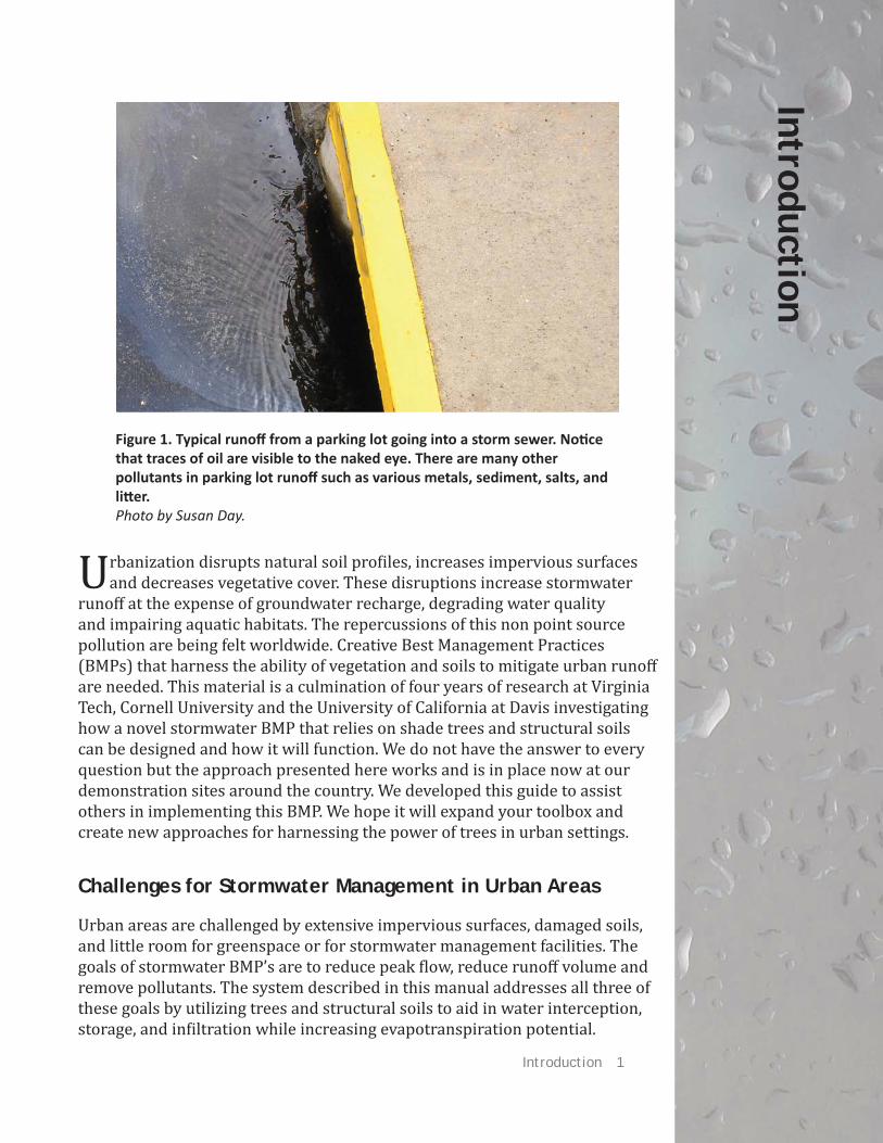
Figure 1. Typical runoff from a parking lot going into a storm sewer. Noti ce that traces of oil are visible to the naked eye. There are many other pollutants in parking lot runoff such as various metals, sediment, salts, and litt er. Photo by Susan Day.

2 Day, S.D. and S.B. Dickinson (eds.) 2008. Managing Stormwater for Urban Sustainability Using Trees and Structural Soils.
Figure 2. This system both serves as a parking lot and as a stormwater management facility. In additi on to this double use of space, the structural soils also provide vastly greater soil volumes for tree root growth than traditi onal parking lot constructi on. Note: Gravel base course is opti onal, since the structural soil is designed to be as strong as a base.Figure by Sarah Dickinson.
Introduction 3
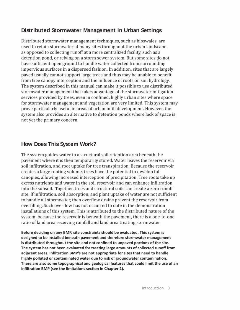
How Does This System Work?
The system guides water to a structural soil retention area beneath the pavement where it is then temporarily stored. Water leaves the reservoir via soil infiltration, and root uptake for tree transpiration. Because the reservoir creates a large rooting volume, trees have the potential to develop full canopies, allowing increased interception of precipitation. Tree roots take up excess nutrients and water in the soil reservoir and can enhance infiltration into the subsoil. Together, trees and structural soils can create a zero runoff site. If infiltration, soil absorption, and plant uptake of water are not sufficient to handle all stormwater, then overflow drains prevent the reservoir from overfilling. Such overflow has not occurred to date in the demonstration installations of this system. This is attributed to the distributed nature of the system: because the reservoir is beneath the pavement, there is a one-to-one ratio of land area receiving rainfall and land area treating stormwater.
Before deciding on any BMP, site constraints should be evaluated. This system is designed to be installed beneath pavement and therefore stormwater management is distributed throughout the site and not confi ned to unpaved porti ons of the site. The system has not been evaluated for treati ng large amounts of collected runoff from adjacent areas. Infi ltrati on BMP’s are not appropriate for sites that need to handle highly polluted or contaminated water due to risk of groundwater contaminati on. There are also some topographical and geological features that could limit the use of an infi ltrati on BMP (see the limitati ons secti on in Chapter 2).
Distributed Stormwater Management in Urban Settings
Distributed stormwater management techniques, such as bioswales, are used to retain stormwater at many sites throughout the urban landscape as opposed to collecting runoff at a more centralized facility, such as a detention pond, or relying on a storm sewer system. But some sites do not have sufficient open ground to handle water collected from surrounding impervious surfaces in a dispersed fashion. In addition, sites that are largely paved usually cannot support large trees and thus may be unable to benefit from tree canopy interception and the influence of roots on soil hydrology. The system described in this manual can make it possible to use distributed stormwater management that takes advantage of the stormwater mitigation services provided by trees, even in confined, highly urban sites where space for stormwater management and vegetation are very limited. This system may prove particularly useful in areas of urban infill development. However, the system also provides an alternative to detention ponds where lack of space is not yet the primary concern.

4 Day, S.D. and S.B. Dickinson (eds.) 2008. Managing Stormwater for Urban Sustainability Using Trees and Structural Soils.
Project Background and Resources
This manual is the result of a series of research studies carried out at Virginia Tech, Cornell University, and the University of California at Davis. This research evaluated multiple aspects of the novel stormwater BMP described here. Work at Virginia Tech focused on tree health and root development in the system, as well as the ability of tree roots to enhance subsurface infiltration in stormwater BMPs. Multiple projects at Cornell examined the physical characteristics of the structural soil mixes as they pertain to storing stormwater, and the feasibility of a wide variety of surface treatments—everything from porous asphalt to turf. Research at Davis in the Department of Land and Water Resources produced baseline evaluations of the ability of several structural soil mixes to remove typical urban runoff contaminants. Each university partnered with private groups or municipalities and installed one or more demonstration sites to evaluate the system as a whole. Overall, the system presented here has been successful. We have prepared this manual to help stormwater engineers, public works departments, and others to put this new approach—or elements of it—into practice.
How this Manual is Organized
The manual is designed to guide you through the features of the system, including its limitations, and how to design a system to suit the site’s needs. Original research papers are referenced and are available from university libraries or by contacting the authors. Brief summaries of this research appear in the manual.
Chapter 1 introduces the stormwater management system, its attributes and limitations.
Chapter 2 provides information on designing a system with structural soils and trees based on the needs of individual sites.
Chapter 3 describes surface treatments that can be used in conjunction with this stormwater management BMP, namely turf and porous pavement. All the information in this section is based on a series of publications from Cornell University’s Urban Horticulture Institute.
Chapter 4 summarizes several original research projects related to the development and evaluation of this system which were conducted by the contributors of this manual. The research in this section was made possible in part through a grant from the United States Department of Agriculture Forest Service Urban & Community Forestry Grants Program on the recommendation of the National Urban & Community Forestry Advisory Council (NUCFAC).

Chapter 1— Trees and Structural Soils- A System Overview 5
Chapter 1— Trees and Structural
Soils- A System O
verview
Stormwater management in urbanized settings faces special challenges: paved surfaces and buildings generate high amounts of runoff while at
the same time leaving little space for constructed stormwater management facilities or for the soil and vegetation combination that could reduce the need for these facilities.
The system described in this manual seeks to address these limitations by using structural soils to simultaneously allow healthy tree growth, water infiltration, and pavement—all on the same land area. Tree root systems and the structural soil that supports them combine to form a shallow but extensive reservoir for capturing and storing stormwater. Structural soils are engineered soil mixes with a high porosity that allow tree roots to penetrate freely, and stormwater to infiltrate rapidly and then be stored until it percolates into the soil beneath. Tree canopies eff ectively intercept rainfall, reducing throughfall to the ground and lengthening the time of runoff concentration into stormwater systems. Trees also actively transpire, taking up water and nutrients present within the reservoir. As runoff infiltrates into the subsoil, pollutants and contaminants can be removed from the stormwater via filtration and/or adsorption (especially in clay soils).
This double use of land surface area (e.g. parking lot and stormwater management) increases land-use efficiency and allows water infiltration over a large area, which more closely mimics natural hydrology than stormwater
Figure 3. An example of a retenti on/detenti on pond adjacent to a conference center on the Virginia Tech campus in Blacksburg, Virginia. This treatment uses space that could be otherwise directed towards other uses. Photo by Susan Day.

6 Day, S.D. and S.B. Dickinson (eds.) 2008. Managing Stormwater for Urban Sustainability Using Trees and Structural Soils.
management systems that concentrate storm flow. In addition, a full tree canopy increases opportunities for returning rainfall to the atmosphere via evapotranspiration and through canopy interception and storage of precipitation. The remainder of this section will introduce the specific components of this system, namely trees and structural soils.
Additi onal benefi ts of trees
• Shading, reducing ambient temperature
• Removing pollutants from the air
• Improve aestheti cs
See htt p://www.fs.fed.us/psw/programs/cufr/ for more informati on
“... trees intercept rainfall, direct precipitation into the ground through trunk flow, and take up stormwater through their roots.”
Trees— Mimicking the Hydrologic Benefi ts of a Forest in the City
Natural forests with their complete canopy cover, large leaf areas, and permeable soils handle rainwater eff ectively through interception and infiltration, returning water to groundwater and the atmosphere and protecting water quality in surface waterways. Replicating elements of this hydrologic cycle in urban settings, however, is difficult—because buildings, infrastructure, people, and other urban denizens compete for land and soil resources.
Urban forests are also widely recognized as an eff ective means of handling stormwater. Like their forestland counterparts, urban trees intercept rainfall, direct precipitation into the ground through trunk flow, and take up stormwater through their roots. In addition, urban tree roots penetrating through typically impermeable urban soil layers into more permeable zones have the potential to increase stormwater infiltration rates. However, urban canopy cover (and thus rain interception) is greatly limited by urban soil conditions such as compaction, reduced rooting volume, and elevated pH. Even open ground in urbanized areas is commonly disturbed or compacted, limiting normal soil hydrologic functions. This system directly addresses the limitations of urban soils to support vegetation and handle water. The system provides a highly permeable rooting environment that can support large trees, thus making these forest benefits available in the city.
“...urban canopy cover (and thus rain interception) is greatly limited by urban soil conditions such as compaction, reduced rooting volume, and elevated pH.”

Chapter 1— Trees and Structural Soils- A System Overview 7
Structural Soils— Supporting Tree Growth and Pavement
Why were structural soils designed?
Typically, soils beneath pavement are compacted to meet engineering requirements to support the loads from vehicles, pavement and structures. Unfortunately, most plant life cannot survive in soils compacted for these purposes. Roots cannot penetrate extremely strong soils. In addition, compacting soil destroys soil structure, collapsing the large pore spaces needed to provide the balance of air and water that roots require. The result is soil that can support pavement but cannot support trees. Structural soils were designed to meet requirements for pavement support while still allowing adequate pore space to support tree roots. Structural soils must be carefully constructed and tested according to verified specifications in order to meet these requirements.
Figure 4. This photograph shows the eff ect of soil volume on tree growth. Both rows of willow oaks were planted at the same ti me on Pennsylvania Avenue, Washington, D.C. The trees on the left are in tree pits, and those on the right are in an open grassed area. Photo by Nina Bassuk.
A good structural soil will have known water-holding, drainage, structural and load-bearing characteristi cs. It should be able to be compacted to 95% of standard Proctor density and sti ll support plant growth. It will also have a research-based track record of success and body of best practi ces. Just any mix of a stone and soil is not a structural soil. Some so-called structural soils have failed miserably when practi ti oners thought they were purchasing a good soil but were just purchasing an untested mix with no research verifi cati on. The two discussed here have been thoroughly tested yet each product should sti ll be required to undergo testi ng aft er installati on to ensure that the fi nal product meets the standards of the specifi cati on. In the case of CU-Structural Soil it must be purchased from licensed producers who are required to test their materials to adhere to a research-based specifi cati on.

8 Day, S.D. and S.B. Dickinson (eds.) 2008. Managing Stormwater for Urban Sustainability Using Trees and Structural Soils.
How do structural soils work ?
Structural soils are engineered to meet compaction requirements for parking lots, roads and other paved surfaces and, at the same time, allow tree root penetration under the pavement. Excavated root systems from structural soils have illustrated that deep rooting of trees in these soils appears to prevent heaving of sidewalks, curbs and gutters by tree roots. Structural soil can therefore expand the soil volume available for the roots of trees in plazas and parking lots and other paved areas.
There are many types of structural soils, but they are based on the same principal: large “structural” particles, typically an angular stone, form a matrix that distributes the load from pavement and structures through stone-to-stone contact ultimately spreading the load across the supporting subsoil. The gaps between the structural particles are then filled with a high quality mineral soil with good water-holding capacity and tilth. Hydrogel is often used in addition to the mineral soil as a tackifier—preventing segregation of the soil during mixing and installation. When structural soils are compacted, they form a rigid matrix while suspending soil as a rooting medium within the interconnected voids of the stone matrix. Roots are able to easily penetrate this uncompacted mineral soil within the compacted stone matrix. As roots expand in the structural soil, they appear to encapsulate, rather than displace the stone matrix or deform temporarily to move between the smallest pores. Because stone is the load-bearing component of the structural soil, the aggregates used should meet regional or state department of transportation standards for pavement base courses.
-Adapted from Bassuk, et al. 2005
Figure 5. Compacted soil from a typical constructi on site. Lack of structure prohibits root penetrati on and growth. Photo by John W. Layman.
Figure 6. CU-Soil, the structural soil developed at Cornell University in the 1990s. Soil parti cles within the media are clearly visible and allow soil nutrients and water holding capacity for healthy root growth. Photo by Ted Haff ner.

Chapter 1— Trees and Structural Soils- A System Overview 9
Table 1 . Comparison of physical properti es of CU-Soil, Carolina Stalite and a silt-loam soil. Note: The Stalite specifi cati ons usually call for sandy loam but plant available moisture with Stalite was tested using the same intersti ti al silty clay loam as was used with the CU-Soil. Table based on informati on from Haff ner, E.C. 2008.
The history of structural soil
This manual examines stormwater management techniques that detain stormwater in under-pavement reservoirs of structural soil. The first of these soils, CU-Soil (Amereq Inc., New York, NY) was developed at Cornell University in Ithaca, New York, in the mid 1990s to address insufficient soil volumes for tree root development. This new type of soil mix resulted from research exploring a means to create a substrate that would both allow adequate tree root growth and support pavement for sidewalks, streets, and parking lots. It is this load-bearing ability that defines structural soils and diff erentiates them from other types of tree soils. Since then, other structural soils have been developed that use other components (e.g. Carolina Stalite, a heat expanded shale (Carolina Stalite Company, Salisbury, NC). The structural component of Carolina Stalite is porous and lightweight in comparison to the gravel used in CUSoil . Because the stone matrix has a rough surface, a tackifier is not required to prevent segregation during mixing.

10 Day, S.D. and S.B. Dickinson (eds.) 2008. Managing Stormwater for Urban Sustainability Using Trees and Structural Soils.
Figure 7. Conceptual diagram of structural soil including stone-on-stone compacti on and soil in intersti ti al spaces. Figure by Sarah Dickinson, adapted from Nina Bassuk.
Contact points where load is transferred
Soil aggregate
Stone particle
Air or water pore spacesaround the soil aggregates
Compactive force
Subsoils
The final component of this system is the existing subsoil upon which the structural soil reservoir will be constructed. For optimum functioning of the system, including healthy root development, the stormwater reservoir should drain within two days. If the subsoil is permeable, or has some permeable areas, infiltration is likely to be rapid because lateral water movement through structural soils is extremely rapid. If soils are impermeable but have permeable layers beneath them, root penetration into the subsoil base may ultimately improve infiltration (see Chapter 4, Tree Root Penetration into Compacted Soils Increases Infiltration), but designs should accommodate the lack of infiltration via placement of overflow pipes (see the blue box on page 15). Although a separation geotextile is not normally required below structural soil sections, when the structural soil is being used as a reservoir for stormwater, subsoil may be saturated at times, resulting in lower soil strength. Therefore, a geotechnical engineer should always be consulted to determine if a separation geotextile is advisable between the subsoil and structural soil components (see Geotextiles section).
Chapter 1— Trees and Structural Soils- A System Overview 11
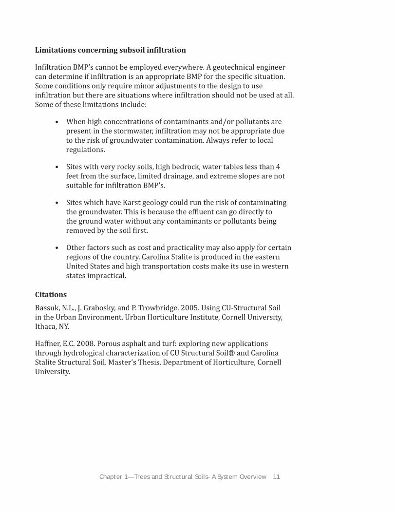
Limitations concerning subsoil infiltration
Infiltration BMP’s cannot be employed everywhere. A geotechnical engineer can determine if infiltration is an appropriate BMP for the specific situation. Some conditions only require minor adjustments to the design to use infiltration but there are situations where infiltration should not be used at all. Some of these limitations include:
• When high concentrations of contaminants and/or pollutants are present in the stormwater, infiltration may not be appropriate due to the risk of groundwater contamination. Always refer to local regulations.
• Sites with very rocky soils, high bedrock, water tables less than 4 feet from the surface, limited drainage, and extreme slopes are not suitable for infiltration BMP’s.
• Sites which have Karst geology could run the risk of contaminating the groundwater. This is because the effluent can go directly to the ground water without any contaminants or pollutants being removed by the soil first.
• Other factors such as cost and practicality may also apply for certain regions of the country. Carolina Stalite is produced in the eastern United States and high transportation costs make its use in western states impractical.
Citations
Bassuk, N.L., J. Grabosky, and P. Trowbridge. 2005. Using CU-Structural Soil in the Urban Environment. Urban Horticulture Institute, Cornell University, Ithaca, NY.
Haff ner, E.C. 2008. Porous asphalt and turf: exploring new applications through hydrological characterization of CU Structural Soil® and Carolina Stalite Structural Soil. Master’s Thesis. Department of Horticulture, Cornell University.

12 Day, S.D. and S.B. Dickinson (eds.) 2008. Managing Stormwater for Urban Sustainability Using Trees and Structural Soils.

Chapter 2— System Design to Meet Site Requirements 13
Chapter 2— System
Design to
Meet Site Requirem
ents
Specifi cations
Surface Treatments
The intent of this BMP is to manage stormwater from the immediate vicinity— it is not meant to handle large amounts of stormwater concentrated from surrounding land areas. Regardless, the system requires that water be directed into a structural soil reservoir beneath the soil surface. There are two options for this that can be used alone or in combination:
• Local rainfall data and runoff calculati ons will determine the minimum depth for the structural soil reservoir. The reservoir can be designed to store the desired rain event (e.g. a 25-year storm).
• For opti mal growth of trees, designs must provide adequate depth and extent of structural soil (see Reservoir Sizing).
• Determine the type of soil and the seasonal water table levels underneath the reservoir. Clay soils will drain much more slowly than sandy soils and will infl uence how much water the reservoir can take and will also determine infi ltrati on and groundwater recharge rates from the reservoir into the subsoil below the reservoir.
• Infi ltrometer measurements may not accurately refl ect drainage rates of the reservoir as a whole. This is because water moves laterally very quickly in structural soils and zones of rapid infi ltrati on can have a disproporti onately large eff ect.
Sustainable site design requires coordination and consultation with diverse professions. For instance, a geotechnical engineer can determine if this
infiltration BMP can be used on your site based on underlying geology and site topography.
A stormwater engineer may determine the quantity of water that the system will need to be able to handle. In addition to water quantity, they should be familiar with the contaminants and pollutants that will be present in the stormwater and local regulation and permit requirements.
Horticulturists, foresters and other qualified plant professionals should be consulted during the design process for choosing tree species and other plantings that will perform well for a given system design and climate.
14 Day, S.D. and S.B. Dickinson (eds.) 2008. Managing Stormwater for Urban Sustainability Using Trees and Structural Soils.
Option 1: Pervious Pavement
Pervious pavement allows rainfall that hits the pavement to infiltrate directly through the wearing surface and into the structural soil reservoir below. Infiltration rates are typically extremely high, much higher than most rainfall rates. There are many types of pervious pavement and the choices continue to expand. For more information on alternatives to traditional impervious pavement, see Chapter 3.
Option 2: Traditional, Impervious Pavement
Water can easily be directed beneath traditional pavement as well. Structural soils allow rapid lateral water movement, so water entering at one point in a structural soil system will seek its own level, spreading out in the reservoir in accordance with the subsoil topography. Gravel swales on the edges of impervious areas allow water to enter the system. This design also can be used as a “backup” system for pervious pavement if there are concerns of clogging.
Reservoir Sizing and Overflow Pipe Design
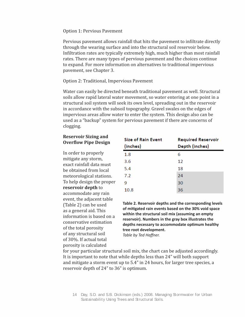
In order to properly mitigate any storm, exact rainfall data must be obtained from local meteorological stations. To help design the proper reservoir depth to accommodate any rain event, the adjacent table (Table 2) can be used as a general aid. This information is based on a conservative estimation of the total porosity of any structural soil of 30%. If actual total porosity is calculated for your particular structural soil mix, the chart can be adjusted accordingly. It is important to note that while depths less than 24” will both support and mitigate a storm event up to 5.4” in 24 hours, for larger tree species, a reservoir depth of 24” to 36” is optimum.
Table 2. Reservoir depths and the corresponding levels of miti gated rain events based on the 30% void space within the structural soil mix (assuming an empty reservoir). Numbers in the gray box illustrates the depths necessary to accommodate opti mum healthy tree root development. Table by Ted Haff ner.

Chapter 2— System Design to Meet Site Requirements 15
Although a structural soil reservoir is a great way to collect rainwater and runoff as regulated by the National Pollution Discharge Elimination System (NPDES) guidelines and decrease demands on existing municipal storm water systems, there may be rain events that generate more runoff than the reservoir below can handle. Installing an overflow pipe above the design stormwater retention level of the reservoir can prevent system failure during extreme weather events.
Placement of the overflow pipe should be determined based on the infiltration rate of the subsoil. Ideally this infiltration rate is calculated for the site as a whole, since rapid infiltration in one area can drain water from less permeable areas. However, if this is not possible, a series of infiltrometer tests should be made after excavation of the reservoir. If infiltration is not adequate to remove water from the rooting zone (the top 18 to 24 inches of structural soil) within 48 hours, the depth of the structural soil reservoir should be increased, or the overflow pipe should be placed such that if water rises to the level of the rooting zone it will be removed by the pipe.
Two systems combined insure against system failure.
1. The structural soil reservoirs at a predetermined depth allow water storage and infi ltrati on to recharge groundwater, if soil conditi ons below the reservoir permit.
2. Traditi onal piping infrastructure located at a level high enough that water will not backup under the pavement if the reservoir is overfi lled by multi ple storm events. The combinati on of the two ensures the system will work during storm events that are larger than the design capacity of the system.
Helpful Hints
• Design to capture all the runoff from the desired storm event. The system can easily be designed to capture all of the runoff from a 100— year storm in most cases. At a minimum, design the reservoir to handle the “water quality storm” for your region. This is the threshold which encompasses 90% of the yearly runoff producti on.
• Infi ltrati on expectati ons: water should not stay in the upper 18 to 24 inches of the reservoir for more than 48 hours. Longer residencies in the tree rooti ng zone may interfere with tree establishment, growth, health, and stability of the rooti ng system.

16 Day, S.D. and S.B. Dickinson (eds.) 2008. Managing Stormwater for Urban Sustainability Using Trees and Structural Soils.
Figure 8. The top illustrati on shows a diversion mound system as used on a roadway. The photo to the left shows the installati on of diversion mounds for an access road. The diversion mounds are circled in red. In the photo to the right you can see the mounds during the structural soil installati on process. Figure by Joe Dove. Photos by Susan Day.
Use additi onal drainage as necessary to decrease fl ooding and inundati on from extreme storm events. Although structural soil is highly porous, fl ooding will occur if the rate of water leaving via infi ltrati on is slower than the rate that water enters the system via rain and runoff (see Reservoir Sizing above).
CU-Soil specifi cati ons require that the mineral soil component of the mix be heavy clay loam or loam with a minimum of 20% clay, because of its greater water- and nutrient-holding capacity. Carolina Stalite structural soil mixes specify a sandy loam since the porous structural parti cles also hold water, but soils with a fi ner texture (i.e. more clay) can also be used. Structural soil should also have organic matt er content ranging from 2-5% to ensure nutrient and water holding while encouraging benefi cial microbial acti vity.

Chapter 2— System Design to Meet Site Requirements 17
Level and Unlevel Sites
Does the reservoir need to be level? A level or nearly level reservoir will promote the maximum distribution of stormwater, allowing the infiltration capacity of the entire subsoil floor to be utilized. However, a sloped system can be designed in two ways. First the subsoil can be excavated in a series of terraces. This is appropriate for a slightly sloped parking area, for example. Alternately, diversion mounds (Figure 8) can be used to direct water under pavement on a slope. This technique was employed at an access road installation in Blacksburg, Virginia. Runoff collected in roadside swales and was then directed under the road pavement with diversion mounds that intersected the swales. In such cases, hydrostatic buildup under the pavement must be prevented by appropriate drainage. Because the reservoir will allow water movement down the slope, it will not store water and infiltration may be minimal.
Designing for Trees to Thrive is Key to System Success
A good, well drained topsoil may be used around the newly installed tree if the pavement opening allows. If this is not practical, structural soil can be used right up to the tree root ball. In drier climates, establishing some tree species directly in structural soil may require frequent irrigation because of the high porosity of the soil. Tree roots need to establish good root-soil contact before they can efficiently extract water from the soil matrix. Tree species that are sensitive to drought during establishment (e.g. swamp white oak (Quercus bicolor) may need close attention to irrigation during the first year or two after planting. Because structural soil gives tree roots a larger volume of soil, irrigation may not be necessary after establishment. Again, this is climate dependent and the expertise of a plant professional with local knowledge should be sought.
While structural soils may have less total moisture on a per volume basis than in conventional soil (around 16% versus a normal 25% in a agricultural soil), the plant available moisture within the structural soil matrix is actually quite comparable to a normal landscape soil (in the range of 8-11% by volume). Traditional planting designs in paved areas surround the planting hole with materials which restrict root penetration and growth. Because the use of structural soils expands total rooting volume, trees have access to greater water resources and can usually be managed very similarly to trees planted in landscape soils. Similar to trees in the landscape, supplemental water should be provided until the tree is established and then irrigation practices should follow local climatic requirements.

18 Day, S.D. and S.B. Dickinson (eds.) 2008. Managing Stormwater for Urban Sustainability Using Trees and Structural Soils.
Geotextiles
By Joseph E. Dove
Geotextiles are part of the broad class of materials called Geosynthetics, which are synthetic polymer materials that are used in a wide range of geotechnical engineering applications such as reinforcement, erosion control, separation, filtration and drainage. General information and educational materials for geosynthetics are available from the International Geosynthetics Society (http://www.geosyntheticssociety.org/guideance.htm).
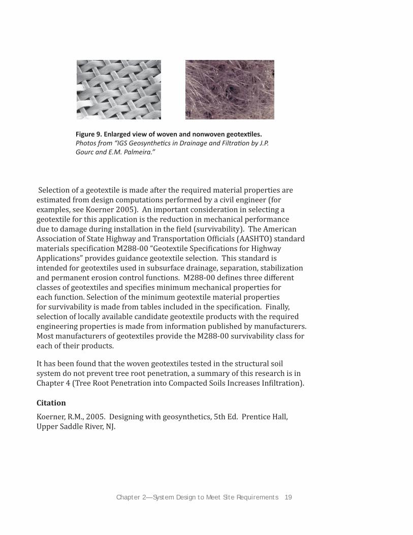
Geotextiles are continuous sheets of flexible, permeable material which have the general appearance of a cloth fabric. They are typically manufactured from polypropylene or polyester and are categorized as either woven or nonwoven. Woven geotextiles are produced by interweaving two orthogonal sets of yarns. They typically have high tensile strength and resistance to elongation. Non-woven geotextiles are manufactured by extruding individual filaments randomly onto a horizontal surface to form a mat. The filaments are then interlocked through needle punching or heat bonding processes. Needlepunched geotextiles typically have high permeability; whereas heat bonded non-woven geotextiles have higher tensile strength characteristics.
In the structural soil system, possible locations for a geotextile include (Figure 8): 1) between the top of the natural (subgrade) soil and the base of the structural soil, and/or 2) below the aggregate base soil supporting the pavement or other surface treatment and the top of the structural soil. In the first case, the geotextile potentially could provide both reinforcing and separation functions. However in the second case, the geotextile provides a separation function only. The reinforcing function arises when the subgrade soil is weak and loads applied by traffic cause deformation of the subgrade, resulting in rutting at the ground surface. This function typically requires geotextiles with high tensile strength. A civil engineer can determine if a reinforcing geotextile is required and recommend tensile strengths for selecting candidate materials, if needed. The separation function in the second case arises to prevent the aggregate base from commingling with the structural soil below. This downward migration can result in decreased pavement performance and a separation geotextile may be warranted as a mitigation measure. A check can be made to assess if the aggregate base soil has a particle size gradation sufficiently fine to permit portions of the base soil to fall into the voids between the underlying structural soil particles. Fortunately, migration of aggregate base soil has not proved to be a problem in other installations. Geotextiles are not be required if the above consequences are not significant to the owner.
Chapter 2— System Design to Meet Site Requirements 19
Figure 9. Enlarged view of woven and nonwoven geotexti les. Photos from “IGS Geosyntheti cs in Drainage and Filtrati on by J.P. Gourc and E.M. Palmeira.”
Selection of a geotextile is made after the required material properties are estimated from design computations performed by a civil engineer (for examples, see Koerner 2005). An important consideration in selecting a geotextile for this application is the reduction in mechanical performance due to damage during installation in the field (survivability). The American Association of State Highway and Transportation Officials (AASHTO) standard materials specification M288-00 “Geotextile Specifications for Highway Applications” provides guidance geotextile selection. This standard is intended for geotextiles used in subsurface drainage, separation, stabilization and permanent erosion control functions. M288-00 defines three diff erent classes of geotextiles and specifies minimum mechanical properties for each function. Selection of the minimum geotextile material properties for survivability is made from tables included in the specification. Finally, selection of locally available candidate geotextile products with the required engineering properties is made from information published by manufacturers. Most manufacturers of geotextiles provide the M288-00 survivability class for each of their products.
It has been found that the woven geotextiles tested in the structural soil system do not prevent tree root penetration, a summary of this research is in Chapter 4 (Tree Root Penetration into Compacted Soils Increases Infiltration).
Citation
Koerner, R.M., 2005. Designing with geosynthetics, 5th Ed. Prentice Hall, Upper Saddle River, NJ.

20 Day, S.D. and S.B. Dickinson (eds.) 2008. Managing Stormwater for Urban Sustainability Using Trees and Structural Soils.
Trees and Other Plants
Trees are an integral component of this stormwater system and must grow well in order to realize maximum stormwater mitigation. By enlarging the rooting volume typically available to trees in paved areas, canopy size has the potential to increase faster and trees may ultimately reach a greater size. Rainfall interception, storage, and ultimately evapotranspiration from leaf surfaces, are directly related to canopy size. In addition, rainfall captured by tree canopies is often directed down limbs and trunks into the soil at the base of the tree—eff ectively bypassing the pavement.
Trees are living organisms and have certain requirements in order to grow well and provide long-term environmental benefits. Here we will outline issues with specific tree selection and site design of special relevance to this stormwater system. However, tree selection should never be undertaken without qualified professional assistance (an urban forester, horticulturist, arborist, or related professional). Pest resistance, urban forest diversity, regional climate factors, growth form, invasive potential and numerous other factors need to be weighed in the final selection.
Soil Chemistry
Structural soils can have very diff erent pHs than local mineral soils. Structural soils with a limestone base will typically have high pH. A structural soil with a granite base may have lower pH. The soil pH determines nutrient availability among other things. A pH of 7 is neutral, with lower pH being acid and a higher pH, basic or alkaline. The ideal pH for most trees is about 5 to 6.5, but urban soils are typically very basic (pH 7.5 to 8.5) because of disturbance, including concrete and limestone debris mixed into the soil. A typical symptom of nutrient deficiency caused by high pH is interveinal chlorosis, or yellowing, of the leaves (Figure 10). If the structural soil used in the system has a high pH, then a “pH tolerant” tree species should be used. These include many elms and ashes and certain maples and oaks as well as a variety of other species (see the tree guide sources at the end of this chapter). The key is to test the structural soil pH and select trees that tolerate it.
Figure 10. Visual comparison of a healthy pin oak leaf (left ) and a chloroti c leaf (right). This chlorosis ulti mately interferes with carbohydrate producti on in the plant and is a result of nutrient defi ciencies stemming from elevated soil pH. Photo by Susan Day.
Chapter 2— System Design to Meet Site Requirements 21
Soil Volume
Trees need enough room to grow—for their roots as well as their canopy. Tree pits (a.k.a. cutouts, planters) should be as large as possible—but how large is that? The key to designing sites that support large trees is to have essentially unlimited rooting space. A typical 4 × 4 ft. cutout with no access to surrounding soil limits tree growth almost immediately. A 25× 25 ft. cutout limits growth very little until the tree is quite large. The usable rooting space provided by any cutout can be expanded by a continuous structural soil bed under pavement. Some species are more adept at exploiting weakness in pavement, penetrating compacted soils, or reaching nearby open spaces. However, the system should be designed to support the tree fully without infrastructure damage. Structural soils have been shown to support deeper root systems than conventional pavement profiles and therefore should supply rooting space without compromising structural integrity. Again, species selection and site conditions must be compatible so a plant professional should be consulted. Always consider local regulations and permitting requirements.
Innovati ve Soluti on: High Shipping Costs of Structural Soils for Western States
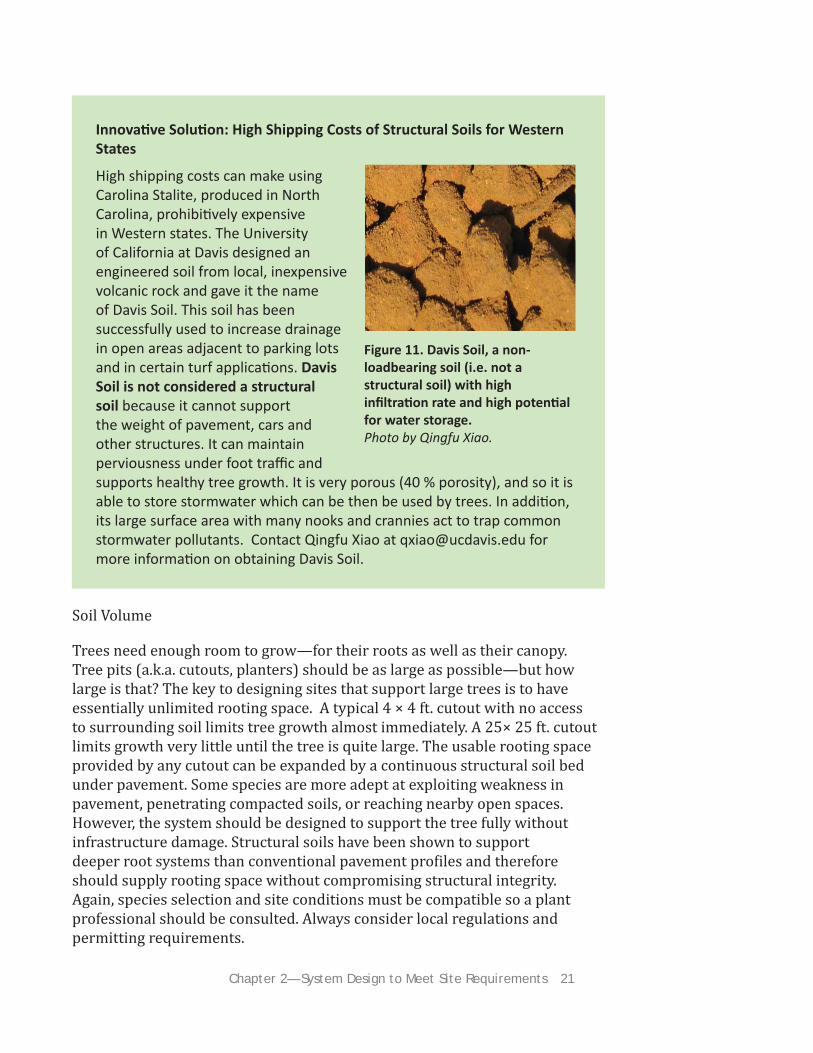
High shipping costs can make using Carolina Stalite, produced in North Carolina, prohibiti vely expensive in Western states. The University of California at Davis designed an engineered soil from local, inexpensive volcanic rock and gave it the name of Davis Soil. This soil has been successfully used to increase drainage in open areas adjacent to parking lots and in certain turf applicati ons. Davis Soil is not considered a structural soil because it cannot support the weight of pavement, cars and other structures. It can maintain perviousness under foot traffi c and supports healthy tree growth. It is very porous (40 % porosity), and so it is able to store stormwater which can be then be used by trees. In additi on, its large surface area with many nooks and crannies act to trap common stormwater pollutants. Contact Qingfu Xiao at [email protected] for more informati on on obtaining Davis Soil.
Figure 11. Davis Soil, a non-loadbearing soil (i.e. not a structural soil) with high infi ltrati on rate and high potenti al for water storage.Photo by Qingfu Xiao.

22 Day, S.D. and S.B. Dickinson (eds.) 2008. Managing Stormwater for Urban Sustainability Using Trees and Structural Soils.
Drainage and Reservoir Capacity Influence Tree Growth
This stormwater system collects water, and how it is designed will influence tree root development. In experiments conducted with flood tolerant species (see Chapter 4, Tree Development in Structural Soils at Diff erent Drainage Rates), root systems developed best when water was retained in the rooting zone no more than 48 hours. Many flood tolerant species, such as swamp white oak (Quercus bicolor) or American elm (Ulmus americana) can survive many months with inundated root systems, but survival alone is not sufficient in urban settings. If infiltration into the soil below the reservoir is rapid, less flood-tolerant species may be selected. If infiltration into the soil below is slow and overflow pipes must be relied upon, then flood-tolerant species should be selected. Depending upon the final use of the space, other plants such as turf or groundcovers can be used if climate permits. See Chapter 3 for more information on surface treatments.
Although high water tables may limit tree rooting depth, when species selection and site design allow trees to root into lower soil regions and penetrate through impervious zones, they may be an eff ective tool to increase infiltration (see Chapter 4, Tree Root Penetration into Compacted Soils Increases Infiltration). This increase can be expected to be most dramatic in highly restrictive soils. To ease establishment, trees should ideally be established in mineral topsoil, with the structural soil components being reserved for under the pavement. However, establishing trees directly in structural soil can simplify installation. If trees will be irrigated regularly during establishment and climatic conditions are appropriate, this approach can be used.
Tree root systems are wide spreading. For maximum tree growth, provide rooting area about twice the diameter of the ultimate canopy for which you are designing.

Chapter 2— System Design to Meet Site Requirements 23
General tree guide sources:
Dirr, Michael. Woody Landscape Plants.
PLANTS Database, htt p://www.plants.usda.gov/
Northern Trees, htt p://orb.at.ufl .edu/TREES/index.html
Tree guide sources for the Eastern United States:
Appleton, B. 2001. New York / Mid Atlanti c Gardener’s Book of Lists. Taylor Publishing Company, Dallas.
Bassukm N.L. Cornell Department of Horti culture Woody Plant Database, htt p://hosts.cce.cornell.edu/woody_plants/
Bassuk, N.L., J. Grabosky, and P. Trowbridge, 2005. Using CU-Structural Soil in the Urban Environment, htt p://www.hort.cornell.edu/uhi/outreach/csc/index.html
Day, S.D. Virginia Urban Tree Selector, htt p://www.cnr.vt.edu/dendro/treeselector/
Trowbridge, P.J. and N.L. Bassuk. 2004. Trees in the Urban Landscape: Site Assessment, Design, and Installati on. Wiley and Sons, New York.
Tree guide sources for the Western United States:
McPherson, E.G., J.R. Simpson, P.J. Peper, Q. Xiao, D.R. Pitt enger and D.R. Hodel. 2001. Tree Guidelines for Inland Empire Communiti es. Sacramento, CA: Local Government Commission
McPherson, E.G., J.R. Simpson, P.J. Peper, K.I. Scott and Q. Xiao. 2000. Tree Guidelines for Coastal Southern California Communiti es. Sacramento, CA: Local Government Commission
McPherson, E.G., J.R. Simpson, P.J. Peper and Q. Xiao. 1999. Tree Guidelines for San Joaquin Valley Communiti es. Sacramento, CA: Local Government Commission

24 Day, S.D. and S.B. Dickinson (eds.) 2008. Managing Stormwater for Urban Sustainability Using Trees and Structural Soils.
Special Concerns
Soil Migrati on
The excavati on of a seven-year-old traditi onal installati on of a London plane (Platanus x acerifolia) tree in CU-Soil with a pervious surface did not show any aggregate migrati on. The pores between stones in the structural soils are mostly fi lled with soil so there are few empty spaces for soil to migrate to.
Frost Heave
By design, structural soils are gap-graded to provide rapid drainage, and limits the silt fracti on to be consistent with very low frost heave suscepti bility as defi ned by the US Corp of Engineers Cold Weather Research Laboratories. However, two important issues are related to this questi on. First, if the design system is installed as a trench under the pavement, there needs to be an awareness of the depths of layers in each pavement layer profi le, and their diff erent frost heave potenti als. The designer needs to be sure there is not a major diff erence in frost heave potenti al at the interface of the two systems or else the pavement surface will move and crack as the total layered systems will behave diff erently. Secondarily, frost concerns also suggest snow removal concerns, so the placement of trees in the system and the needs of snow removal and storage on site need to be addressed with the maintenance authority to prevent the loss of the trees or damage to the system.
Observati on of structural soil throughout the US and Canada shows that the depth of the reservoir negates any heaving due to consequent freezing and thawing. Additi onally, there have been no observed instances of freeze/thaw damage in any structural soil installati ons in the fi ft een plus years since its incepti on.

Chapter 3— Surface Treatments 25
Chapter 3— Surface Treatm
entsThis section describes two surface treatments that can be used with this
system: turf and porous pavement. The sections in this chapter are summaries from manuals published by the Urban Horticulture Institute (Cornell University). A citation to the complete manual is provided at the end of each section.
Structural Soils and TurfBy Nina Bassuk, Ted Haffner, Jason Grabosky, and Peter Trowbridge
Introduction
Turf is primarily used as a ground cover in residential lawns, parks, playgrounds and athletic fields. It is used both for providing a sense of open space and as a protective surface for recreation. If turf is properly installed, it can have additional uses such as limited access fire lanes, and parking lots. In these instances, turf can contribute to a sense of open green space and reduce temperatures in urban settings that may otherwise be paved.
When turf is used for these applications, however, it is susceptible to traffic which will compact the soil. These situations also limit drainage, healthy root growth, and the ability of turf to grow at all.
Cornell Developments in Turf Use
Cornell University has combined turf with structural soil to create a healthy growing medium for the grass that withstands traffic, is designed
Figure 12. Area of park used for a weekly farmers market in Chicago. Compacti on from foot and vehicle traffi c has denuded the grass in this secti on of the park. Photo by Ted Haff ner.
Figure 13. Photo simulati on of turf-covered perimeter parking at a big box lot in Ithaca, NY. For best results, turf should be only placed in parking stalls and not in driving lanes of the parking lot. Photosimulati on by Ted Haff ner.

26 Day, S.D. and S.B. Dickinson (eds.) 2008. Managing Stormwater for Urban Sustainability Using Trees and Structural Soils.
to be virtually maintenance free, and can be used in areas that receive high levels of both pedestrian and vehicular traffic. These areas include open field public gathering spaces, fire lanes, and parking lots.
Structural soils have two benefits. The first is that structural soil is designed to be compacted, and will therefore withstand heavy amounts of traffic, allowing both people, cars and temporary structures to safely use a turf covered surface installed on structural soil. In addition, the system can allow water to infiltrate the turf surface and hold it in a reservoir underneath the grass. Increased water and air within the structural soil media not only allows for healthier root and shoot growth for the grass, but also allows rainwater and runoff to be collected and held within the reservoir in large amounts until it can slowly infiltrate into the ground below. This reduces the need for drainage and sewer system infrastructure and also recharges the groundwater levels over time. This combination, then, not only serves the environment from a water quality standpoint, but also adds a “sustainably green” component to highly urbanized areas.
Figure 14. Aerial view of structural soil and turf experimental plots at Cornell University in Ithaca, NY. Surface Treatments: PA= Porous Asphalt, Z= Zoysia Grass, F= Tall Fescus, C= Traditi onal Asphalt. Graphics by Ted Haff ner. Underlying photo by Google Earth.

Chapter 3— Surface Treatments 27
Figure 15. Constructi on detail for turfgrass and structural soil profi le. Note that the 24” reservoir depth was based on local rainfall data and will vary by region according to the local rainfall data and/or anti cipated runoff amounts.Figure by Ted Haff ner.
• Minimize vehicular wear on the turf as much as possible. To do this, place turf only in parking stalls and not the driving lanes of the lot.
• Angle parking stalls to minimize turning from automobile wheels. Excessive turning causes the turf grass leaf blades to tear and can create bare patches in the turf. Research indicates that turf can recover from this damage but it takes extra ti me.
• Use turf only in overfl ow parking areas on the outskirts of large parking lots.
• Use inset stonework between stalls, or posts to demark parking stalls. This design maneuver may cost more upfront to install, but will save ti me and money during post-installati on maintenance.
• Specify proper post-installati on maintenance regimes. Mowing every 10 days is necessary, as is the applicati on of annual fall ferti lizati on with proper applicati on rates.
• Never snow plow the turf porti on of the parking lot. The blades from the plow will damage the turf surface, removing the turf and necessitati ng costly replacement.

28 Day, S.D. and S.B. Dickinson (eds.) 2008. Managing Stormwater for Urban Sustainability Using Trees and Structural Soils.
Designing and Working with Turf and Structural Soil
Contrary to popular belief, growing healthy turfgrass is very difficult to achieve. With many diff erent factors involved in the process, it is not as simple as spreading seed or unfurling a roll of sod. Proper decision making at every step of the planning, design, installation, and post-installation process are absolutely necessary.
Working with turf and structural soil requires a change in the way that designers and contractors go about their work. Rather than just installing sod or seeding grass directly onto existing soil, entire areas will need to be excavated to a depth of at least 18” to 24” (to accomodate stormwater- see Table 2), depending on the desired reservoir depth, and filled with structural soil. Once the structural soil mix is in place it must be compacted with a vibratory or rolling compactor. Once compacted, the sod should be installed directly onto the structural soil and then irrigated for a number of weeks until established. Once established, research indicates that maintenance requirements are minimal, other than regular mowing and periodic fertilization.
With the previous guidelines, a few simple construction details will provide the bulk of information needed for bidding and installation of a construction project. While a few simple drawings are helpful, keep in mind that every design is diff erent and will necessitate the level of detail appropriate for each diff erent design scenario. Additional details will be needed for, ADA compliance curbing, tree planting and staking, hydrant water supply, signage
FAQs
What type of maintenance is needed for a turfgrass and structural soil system?
Our research was performed with the idea of the most basic maintenance regime in mind. Test plots on the Cornell campus received no maintenance other than routi ne mowing once every 7 to 10 days during the growing season. Additi onal annual ferti lizati on in the fall is recommended with the proper applicati on rates.
What happens when neighboring tree roots expand in structural soil?
There will come a ti me when the roots will likely displace the stone because there are no pavement layers above the structural soil, but if the roots are, as we have observed, deep down in the profi le, the pressure they generate during expansion would be spread over a larger surface area. We have seen roots move around the stone and actually surround some stones in older installati ons, rather than displace the stones.

Chapter 3— Surface Treatments 29
Case Study
Turf on CU-Soil has been successfully used at a Mercedes dealership (Crown Automobile) in Alabama. At this installati on, the soil in an enti re median was excavated and replaced with CU-Soil and then sod was placed on top. The median can now properly withstand the compacti on from the weight of the cars and serves as a fl exible open space for the dealership, providing impromptu space to display inventory, or as overfl ow parking for the dealership. Aft er three years, this installati on is maintenance free and as healthy as the day it was installed.
Figure 16. In winter when the sod is dormant, the median serves as additi onal storage and display space for the dealership inventory. This fl exibility is invaluable to the dealership. Photo by Bill Isaacs.
Citation:
Haff ner, E.C. 2008. Porous asphalt and turf: exploring new applications through hydrological characterization of CU Structural Soil and Carolina Stalite Structural Soil. Master’s Thesis. Department of Horticulture, Cornell University.

30 Day, S.D. and S.B. Dickinson (eds.) 2008. Managing Stormwater for Urban Sustainability Using Trees and Structural Soils.
Using Porous Pavement on Structural Soils By Ted Haffner, Nina Bassuk, Jason Grabosky, and Peter Trowbridge
A porous asphalt system allows water to flow through the pavement and into a reservoir of structural soil beneath the surface. There water can slowly filter into the subgrade below, naturally recharging groundwater levels.
Porous asphalt is similar to traditional asphalt in every way but the mix specification. Unlike traditional asphalt, porous asphalt leaves out fine particles in the mix. Leaving out these finer particles leaves gaps within the profile of the asphalt that allow water to flow through the pavement, rather than over the pavement. In order for the water to properly infiltrate, slopes on porous pavements should be limited to 1-6%.
Figure 17. The left fi gure shows rain on a traditi onal asphalt parking lot- aft er it hits the surface it typically runs off into a storm sewer system. The right fi gure shows rain on a porous asphalt parking lot- aft er it its the surface it infi ltrates through the pavement into the structural soil reservoir below. Water then infi ltrates into the ground, recharging the groundwater over ti me. Both fi gures by Ted Haff ner.
Structural soil and porous asphalt are a new combination of 15- and 30-year-old technologies. As such, the first installation of this combination exists in Ithaca, NY and was installed in 2005. Porous asphalt parking lots are numerous and the oldest include the Walden Pond Reservation in Concord, MA, the Morris Arboretum in Philadelphia, PA, as well as an ever expanding list of corporations and universities across the United States. Structural soil has been used extensively without porous asphalt pavement and the two oldest installations date to 1994; the first is a honeylocust (Gleditsia triacanthos) planting at the Staten Island Esplanade Project in New York City, the second is a London planetree (Platanus acerifolia) planting on Ho Plaza on the Cornell campus, Ithaca, NY. There are now hundreds of installations of various sizes across the United States and Canada.

Chapter 3— Surface Treatments 31
Figure 18. A comparison of traditi onal asphalt (left ) and porous asphalt (right) when wet. The gaps created by leaving out the fi ner parti cles in porous asphalt allow water to infi ltrate pavement and into the structural soil reservoir below. As a result, porous asphalt appears dull when wet, because water runs through and does not pond, which creates a high fricti on surface. Photo by Ted Haff ner.
Concerns of Clogging
The best maintenance for any type of porous pavement is a vacuum treatment every two to five years to remove sediment from the pores within the pavement, although the oldest installations have never been vacuumed and show little eff ects of clogging. Porous asphalt systems should not be pressure washed since this treatment further embeds sediment within the surface. Additionally, porous asphalt systems should never be sealed. Once a sealant is applied, the system will not work ever again.
Porous Bituminous Asphalt Specification
Ithaca, NY Porous Asphalt Medium Duty Parking Lot
1. Bituminous surface course for porous paving shall be two and one-half (2.5) inches thick with a bituminous mix of 5.5% to 6% by weight dry aggregate. In accordance with ASTM D6390, draindown of the binder shall be no greater than 0.3%. If more absorptive aggregates, such as limestone, are used in the mix then the amount of bitumen is to be based on the testing procedures outlined in the National Asphalt Pavement Association’s Information Series 131 – “Porous Asphalt Pavements” (2003) or NYSDOT equivalent.

32 Day, S.D. and S.B. Dickinson (eds.) 2008. Managing Stormwater for Urban Sustainability Using Trees and Structural Soils.
2. Use neat asphalt binder modified with an elastomeric polymer to produce a binder meeting the requirements of PG 76-22. The elastomeric polymer shall be styrene-butadiene-styrene (SBS), or approved equal, applied at a rate of 3% by total weight of the binder. The composite materials shall be thoroughly blended at the asphalt refinery or terminal prior to being loaded into the transport vehicle. The polymer modified asphalt binder shall be heat and storage stable.
3. Aggregate in the asphalt mix shall be minimum 90% crushed material and have a gradation of:
U.S. Standard
Sieve Size Percent Passing
½” (12.5mm) 100
3/8” (9.5mm) 92-98
4 (4.75mm) 32-38
8 (2.36mm) 12-18
16 (1.18mm) 7-13
30 (600 mm) 0-5
200 (75 mm) 0-3
4. Add hydrated lime at a dosage rate of 1.0% by weight of the total dry aggregate to mixes containing granite. Hydrated lime shall meet the requirements of ASTM C 977. The additive must be able to prevent the separation of the asphalt binder from the aggregate and achieve a required tensile strength ratio (TSR) of at least 80% of the asphalt mix.
The asphaltic mix shall be tested for its resistance to stripping by water in accordance with ASTM D-3625. If the estimated coating area is not above 95 percent, anti-stripping agents shall be added to the asphalt.
Citation:
Haff ner, T., Bassuk, N.L., Grabosky, J., and P. Trowbridge. 2007. Using Porous Asphalt and CU-Structural Soil. http://www.hort.cornell.edu/uhi/outreach/csc/index.html Urban Horticulture Institute, Cornell University, Ithaca, NY.

Chapter 3— Surface Treatments 33Chapter 4— Research and Recommendations 33
Chapter 4— Research and
Recomm
endationsTree Root Penetration into Compacted Soils Increases Infi ltration Based on Research by Julia Bartens, Susan Day, Joseph E. Dove, J. Roger Harris, and Theresa Wynn, Virginia Tech
Research Summary
A container experiment with recently transplanted black oak (Quercus velutina) and red maple (Acer rubrum) tested whether roots can penetrate into compacted soil and once they penetrate, if they can increase water infiltration. Both tree species were grown in pine bark and surrounded on all sides and the bottom with compacted soils. Within 12 weeks, both tree species were able to penetrate into compacted soil and increase infiltration. Roots penetrating into subsoil increased infiltration by 153%. There was no diff erence in performance between black oak (coarse roots) and red maple (fine roots).
In a second container experiment, green ash (Fraxinus pennsylvanica) were grown in CU-Soil and were separated from the compacted subsoil by geotextile. Roots were able to penetrate into compacted subsoil and increase the infiltration rate by a factor of 27.
Next Steps/Research Needs
This research was done in containers and research confirming that this also applies to larger scale trees in the ground needs to be done. Tree species with diff erent requirements should also be observed.
Citation
Bartens, J., S. D. Day, J. R. Harris, J. E. Dove, and T. M. Wynn. 2008. Can urban tree roots improve infiltration through compacted subsoils for stormwater management? Journal of Environmental Quality, 37 (6):2048-2057.
Figure 19. Ash roots penetrati ng geotexti le aft er compacted subsoil has been washed away. Roots increased infi ltrati on by a factor of 27. Photo by Susan Day.

34 Day, S.D. and S.B. Dickinson (eds.) 2008. Managing Stormwater for Urban Sustainability Using Trees and Structural Soils.
Tree Development in Structural Soils at Different Drainage Rates Based on Research by Julia Bartens, Susan Day, J. Roger Harris, Joseph E. Dove, and Theresa Wynn, Virginia Tech
Research Summary
A container experiment involving 2 tree species (swamp white oak (Quercus bicolor), and green ash (Fraxinus pennsylvanica), 3 drainage rates (slow, medium, rapid), and 2 structural soils (CU-Soil and Carolina Stalite) evaluated the optimal reservoir detention times for tree root development and water uptake from the reservoir. Structural soils had an impact on root distribution— tree roots grew wider in Carolina Stalite than with CU-Soil. Drainage rate also had an impact on tree growth; Root:shoot ratios for swamp white oak were much higher for the slow drainage treatment and trees were smaller with shallow root systems. Green ash trees were more flood tolerant and no diff erence in Root:shoot ratios for the diff erent drainage rates was observed but roots did grow deepest in the rapidly draining treatment.
Recommendations based on this research
In general, water should drain from the parking lot within 2 days so adequate root systems can develop. For water uptake from the reservoir it is clearly beneficial to have root systems explore the full reservoir depth. Prolonged inundation can prevent this deeper root exploration, depending upon species. Transpiration rates were varied but similar to trees grown in traditional landscapes. Of course, size of tree canopy is important in determining amount of water that can be removed. In general, the largest trees with the best developed root systems removed the greatest amount of water from the stormwater reservoirs.
Next Steps/Research Needs
Temperatures of the structural soils could be compared in future experiments because this could also be aff ecting the root growth and maybe of interest if water does exit the system through an overflow pipe (because of the potential for thermal pollution of waterways). In addition, a field study would give more information about lateral root growth (which was limited in this experiment because of containers). Although tree species with similar flood/drought tolerances can be expected to respond similarly, more species trials would be useful.

Chapter 4— Research and Recommendations 35
Citation
Bartens, J., J. R. Harris, S. D. Day, J. E. Dove, and T. M. Wynn. 2008 Ecologically integrated stormwater distribution using urban trees and structural soils. (in review)
Drainage Rate at the Mini Parking Lot Demonstration Site in Blacksburg, VA Based on Research by Mona Dollins, Virginia Tech
Research Summary
A Mini Parking Lot demonstration site which had a Carolina Stalite structural soil reservoir (18’ x 18’ x 23”) was completely filled with water and then allowed to naturally drain into the clay textured subsoil beneath. The water levels were checked from 15 observation wells every 5 minutes (during the first 40 minutes) to 15 minutes (during the remainder of the experiment) to determine the speed of drainage and lateral water movement through the system.
Within 2.5 hours, the water had completely drained from the reservoir. Lateral water movement within the reservoir was very rapid through the structural soil media traveling over 18 feet in a matter of minutes.
Next Steps/Research Needs
Drainage data from larger systems, at varying depths, and diff erent types of subsoils should be tested to gain better understanding of the systems behavior in diff erent conditions.
Note: some fine textured soils will not drain as quickly as they did in this trial. An initial soil drainage test and incorporating an overflow pipe is always recommended (see the blue box on page 15).

36 Day, S.D. and S.B. Dickinson (eds.) 2008. Managing Stormwater for Urban Sustainability Using Trees and Structural Soils.
System Effects on Water Quality Based on Research by Qingfu Xiao, University of California at Davis
Research Summary
Research shows that 97.9-99% of the hydrocarbons found in pollutants such as oil are suspended within the first few inches of the surface. During suspension, microorganisms biodegrade the hydrocarbons into their constituent parts of simple chemical components which cease to exist as pollutants and render them harmless to the environment.
Surface runoff from four types of parking lots was collected (commercial, older institutional (>10 years), newer institutional (<3 years), and residential). Pollutant removal (nutrients, heavy metals, soil column tests) by 3 types of substrates (CU-Soil, Davis Soil, and Carolina Stalite) were compared. Tests: single event test, multiple events test and synthetic runoff test.
All three engineered soils were eff ective at removing nutrients and materials in polluted surface runoff . Pollutant removal rates were strongly related to the type and size of the rainfall event.
Next Steps/Research Needs
Research that determines the pollutant saturation point for these soils should be done. Also, the figures reported are baseline data for structural soils alone. Once tree roots explore the reservoir it is expected that they would enhance pollutant removal— but research is needed to accurately evaluate these eff ects.
How eff ective the system is at removing/degrading nutrients and pollutants with trees in the system.
How can pollutant fluxes be balanced in the system? In heavily polluted areas other BMPs need to be used for pre-treating the surface runoff .

Chapter 4— Research and Recommendations 37
Table 3. Pollutant removal of single storm event. CU= CU Soil, CS= Carolina Stalite, and DS= Davis Soil.Table by Qingfu Xiao.
Table 4. Pollutant removal of multi ple storm events. CU= CU Soil, CS= Carolina Stalite, and DS= Davis Soil.Table by Qingfu Xiao.

38 Day, S.D. and S.B. Dickinson (eds.) 2008. Managing Stormwater for Urban Sustainability Using Trees and Structural Soils.

Resources 39
Helpful Resources
Balages, J.D., L. Legret, and H. Madiec, 1995. Permeable pavements: pollution management tools. Water Science and Technology, 32 (1): 49-56.
Barley, K., 1963. Influence of soil strength on growth of roots. Soil Science, 96: 175-180.
Bartens, J. 2006. Trees and structural soil as a stormwater management system in urban setting. Master’s Thesis. Department of Horticulture, Virginia Tech.
Bartens, J., S. D. Day, J. R. Harris, J. E. Dove, and T. M. Wynn. 2008. Can urban tree roots improve infiltration through compacted subsoils for stormwater management? Journal of Environmental Quality, 37 (6):2048-2057.
Bassuk, N.L., J. Grabosky, and P. Trowbridge. 2005. Using CU-Structural Soil in the Urban Environment. Urban Horticulture Institute, Cornell University, Ithaca, NY. http://www.hort.cornell.edu/uhi/outreach/csc/index.html
Bramley, H., J. Hutson, and S.D. Tyerman, 2003. Floodwater infiltration through root channels on a sodic clay floodplain and the influence on a local tree species Eucalyptus largiflorens. Plant Soil, 253: 275-286.
Bühler, O., P. Kristoff erson, and S.U. Larson, 2007. Growth of street trees in Copenhagen with emphasis on the eff ect of diff erent establishment. Arboriculture & Urban Forestry, 33(5): 330-337.
Cahill, T., 1993. Porous pavement with underground recharge beds, engineering design manual. Cahill Design Associates, West Chester, PA.
Cahill, T., 2008. A second look at porous pavement/underground recharge. Watershed Protection Techniques, US Environmental Protection Agency, 1: 76-78.
Cahill, T., M. Adams, and C. Marm, 2003.Porous asphalt: the right choice for porous pavements, Hot Mix Asphalt Technology, September/October.
Carolina Stalite Specifications, Section 2.1 Structural Soil Mix. www.Stalite.com.
Colandini, V., M. Legret, Y. Brosseaud, and J.D. Balades, 1995. Metallic pollution in clogging materials of urban porous pavements. Water Science and Technology, 32(1): 57-62.
Cresswell, H.P. and J.A. Kirkegaard, 1995. Subsoil amelioration by plant roots: the process and the evidence. Australian Journal of Soil Restoration, 33: 221-239.

40 Day, S.D. and S.B. Dickinson (eds.) 2008. Managing Stormwater for Urban Sustainability Using Trees and Structural Soils.
Day, S. and N. Bassuk, 1994. A review of the eff ects of soil compaction and amelioration treatments on landscape trees. Journal of Arboriculture, 20: 9-17.
Day, S.D., J.R. Seiler, and N. Persaud, 2000. A comparison of root growth dynamics of silver maple and flowering dogwood in compacted soil at diff ering soil water contents. Tree Physiology, 20: 257-263.
Evans, M., N.L. Bassuk, and P.J. Trowbridge, 1990. Street trees and sidewalk construction. Landscape Architecture. 80(3): 102-103.
Ferguson, B.K., 1996. Preventing the problems of urban runoff . Renewable Resources Journal, Winter 1995-1996: 14-18.
Ferguson, B.K., 2005. Porous Pavements. Taylor and Francis Group; Boca Raton, London, New York, Singapore.
Goldstein, J., N.L. Bassuk, P. Lindsey, and J. Urban, 1991. From the ground down. Landscape Architecture, 81(1): 66-68.
Grabosky, J. 1996. Developing a structural soil material with high bearing strength and increased rooting volumes for street trees under sidewalks. Master’s Thesis. Department of Horticulture, Cornell University.
Grabosky, J. 1999. Growth Response of Three Tree Species in Sidewalk Profiles. Doctoral Dissertation. Department of Horticulture, Cornell University.
Grabosky, J. and N. Bassuk, 1995. A new urban tree soil to safely increase rooting volumes under sidewalks. Journal of Arboriculture, 21: 187-200.
Grabosky, J. and N. Bassuk, 1996. Testing of structural urban tree soil materials for use under pavement to increase street tree rooting volumes. Journal of Arboriculture, 22: 255-263.
Grabosky, J. and N. Bassuk, 1998. Urban tree soil to safely increase rooting volume. Patent No. 5,849,069. U.S.P.a.T. Office.
Grabosky, J. and N. Bassuk, 2008. Sixth- and tenth- year growth measurements for three tree species in a load-bearing stone-soil blend under pavement and a tree lawn in Brooklyn, NY, U.S. Arboriculture & Urban Forestry, 34(4): 265-266.
Grabosky, J., N.L. Bassuk, L. Irwin, and H. Van Es, 2001. Shoot and root growth of three tree species in sidewalks. Journal of Environmental Horticulture, 19(4):206-211.
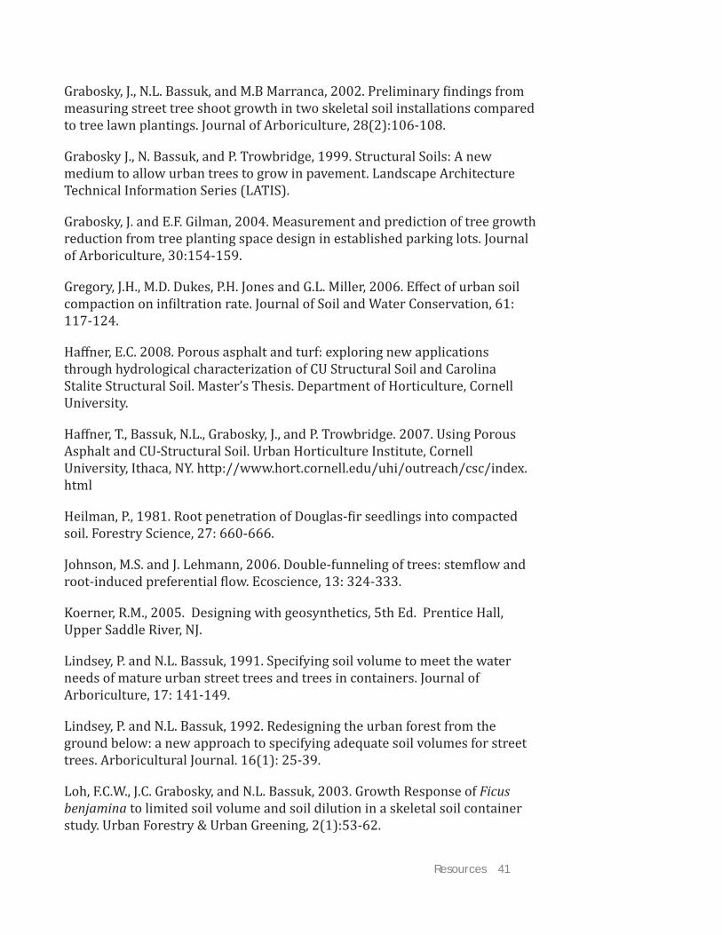
Resources 41
Grabosky, J., N.L. Bassuk, and M.B Marranca, 2002. Preliminary findings from measuring street tree shoot growth in two skeletal soil installations compared to tree lawn plantings. Journal of Arboriculture, 28(2):106-108.
Grabosky J., N. Bassuk, and P. Trowbridge, 1999. Structural Soils: A new medium to allow urban trees to grow in pavement. Landscape Architecture Technical Information Series (LATIS).
Grabosky, J. and E.F. Gilman, 2004. Measurement and prediction of tree growth reduction from tree planting space design in established parking lots. Journal of Arboriculture, 30:154-159.
Gregory, J.H., M.D. Dukes, P.H. Jones and G.L. Miller, 2006. Eff ect of urban soil compaction on infiltration rate. Journal of Soil and Water Conservation, 61: 117-124.
Haff ner, E.C. 2008. Porous asphalt and turf: exploring new applications through hydrological characterization of CU Structural Soil and Carolina Stalite Structural Soil. Master’s Thesis. Department of Horticulture, Cornell University.
Haff ner, T., Bassuk, N.L., Grabosky, J., and P. Trowbridge. 2007. Using Porous Asphalt and CU-Structural Soil. Urban Horticulture Institute, Cornell University, Ithaca, NY. http://www.hort.cornell.edu/uhi/outreach/csc/index.html
Heilman, P., 1981. Root penetration of Douglas-fir seedlings into compacted soil. Forestry Science, 27: 660-666.
Johnson, M.S. and J. Lehmann, 2006. Double-funneling of trees: stemflow and root-induced preferential flow. Ecoscience, 13: 324-333.
Koerner, R.M., 2005. Designing with geosynthetics, 5th Ed. Prentice Hall, Upper Saddle River, NJ.
Lindsey, P. and N.L. Bassuk, 1991. Specifying soil volume to meet the water needs of mature urban street trees and trees in containers. Journal of Arboriculture, 17: 141-149.
Lindsey, P. and N.L. Bassuk, 1992. Redesigning the urban forest from the ground below: a new approach to specifying adequate soil volumes for street trees. Arboricultural Journal. 16(1): 25-39.
Loh, F.C.W., J.C. Grabosky, and N.L. Bassuk, 2003. Growth Response of Ficus benjamina to limited soil volume and soil dilution in a skeletal soil container study. Urban Forestry & Urban Greening, 2(1):53-62.

42 Day, S.D. and S.B. Dickinson (eds.) 2008. Managing Stormwater for Urban Sustainability Using Trees and Structural Soils.
McPherson G., J.R. Simpson, P.J. Peper, S.E. Maco, and Q. Xiao, 2005. Municipal forest benefits and costs in five US cities. Journal of Forestry 103:411-416.
Smiley, T. E., L. Calfee, B. Fraedrich and E.J. Smiley, 2006. Compaction of structural soil and noncompacted soils for trees surrounded by pavement. Arboriculture and Urban Forestry, 32(4): 164-169.
Thelen, E., W.C. Grover, A.J. Hoiberg, and T.I. Haigh, 1972. Investigation of Porous Pavements for Urban Runoff Control. Environmental Protection Agency.
Trowbridge, P. and N.L. Bassuk, 2004. Trees in the urban landscape: site assessment, design and installation. Chapter 3:61-81. Wiley and Sons, Inc.
Trowbridge, P. and N.L. Bassuk, 1999. Redesigning paving profiles for a more viable urban forest. ASLA Proceedings Annual Conference, pp. 350-351. 13(2): 64-71.
Xiao Q., and E. McPherson, 2003. Rainfall interception by Santa Monica’s municipal urban forest. Urban Ecosystems, 6:291-302.

Appendices 43
Appendices
Note: These structural soil specifications are provided as a convenience to the reader and are presented “as is” from resources provided by the manufacturers or licenses. Inclusion of the specifications in no way represents an endorsement of or warranty of these products by Virginia Tech, Cornell University or University of California at Davis or any of their employees.
CU-Soil is a patented material and must be purchased from a licensed supplier. Amereq (http://www.amereq.com/) licenses the manufacturing of CU-Soil to ensure quality control of installations.
Carolina Stalite is composed primarily of a manufactured component available from Carolina Stalite Company (Salisbury, NC). It is available through the horticultural division of Carolina Stalite (www.permatill.com).
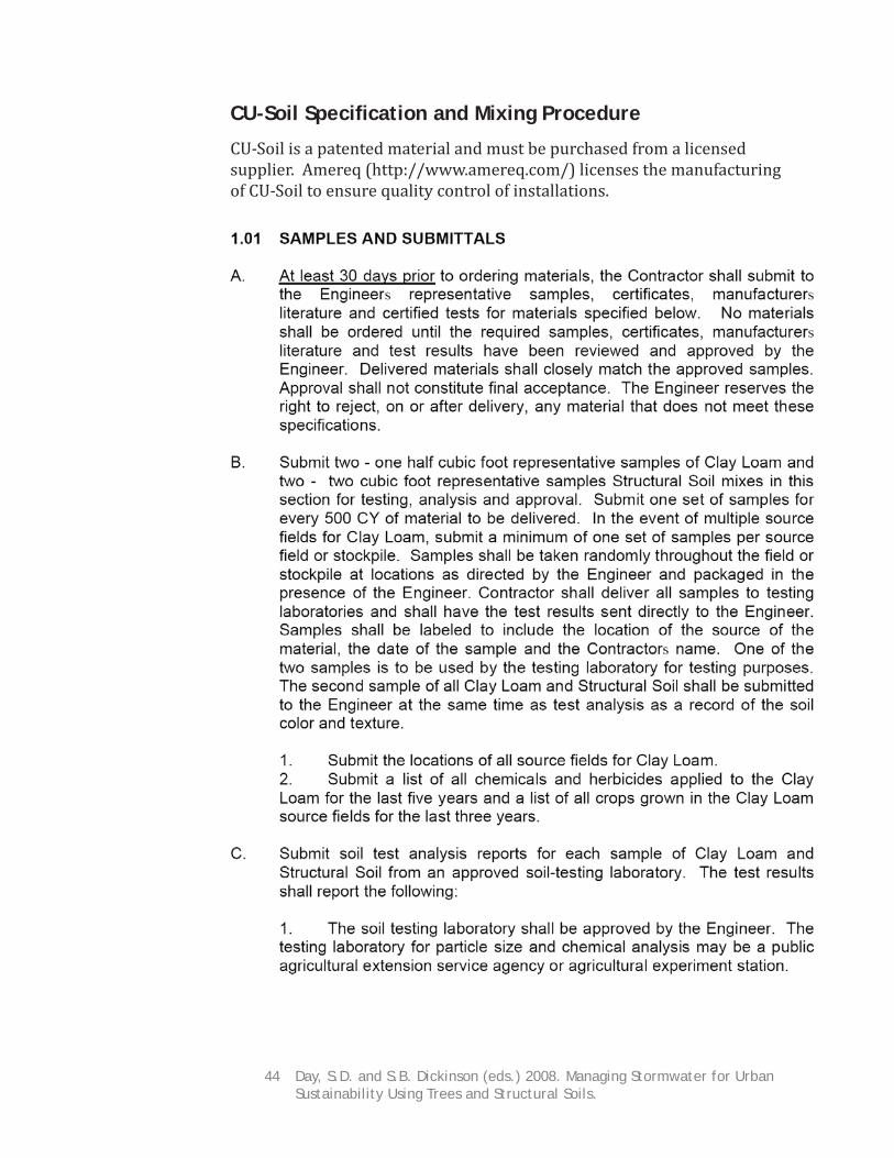
44 Day, S.D. and S.B. Dickinson (eds.) 2008. Managing Stormwater for Urban Sustainability Using Trees and Structural Soils.
CU-Soil Specifi cation and Mixing Procedure
CU-Soil is a patented material and must be purchased from a licensed supplier. Amereq (http://www.amereq.com/) licenses the manufacturing of CU-Soil to ensure quality control of installations.

Appendices 45
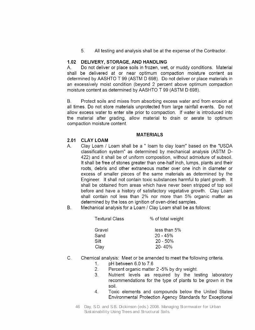
46 Day, S.D. and S.B. Dickinson (eds.) 2008. Managing Stormwater for Urban Sustainability Using Trees and Structural Soils.

Appendices 47

48 Day, S.D. and S.B. Dickinson (eds.) 2008. Managing Stormwater for Urban Sustainability Using Trees and Structural Soils.

Appendices 49

50 Day, S.D. and S.B. Dickinson (eds.) 2008. Managing Stormwater for Urban Sustainability Using Trees and Structural Soils.

Appendices 51
Carolina Stalite Structural Soil Specifi cation

52 Day, S.D. and S.B. Dickinson (eds.) 2008. Managing Stormwater for Urban Sustainability Using Trees and Structural Soils.

Appendices 53

54 Day, S.D. and S.B. Dickinson (eds.) 2008. Managing Stormwater for Urban Sustainability Using Trees and Structural Soils.
Carolina Stalite Mixing Specifi cation

Appendices 55