Embed Size (px)
Citation preview

Managing GPU Concurrency in Heterogeneous Architectures
Onur Kayıran∗ Nachiappan Chidambaram Nachiappan∗ Adwait Jog∗ Rachata Ausavarungnirun†
Mahmut T. Kandemir∗ Gabriel H. Loh‡ Onur Mutlu† Chita R. Das∗∗ The Pennsylvania State University † Carnegie Mellon University ‡ Advanced Micro Devices, Inc.
Email: ∗{onur, nachi, adwait, kandemir, das}@cse.psu.edu, †{rachata, onur}@cmu.edu, ‡[email protected]
Abstract—Heterogeneous architectures consisting of general-purpose CPUs and throughput-optimized GPUs are projectedto be the dominant computing platforms for many classesof applications. The design of such systems is more complexthan that of homogeneous architectures because maximizingresource utilization while minimizing shared resource interfer-ence between CPU and GPU applications is difficult. We showthat GPU applications tend to monopolize the shared hardwareresources, such as memory and network, because of their highthread-level parallelism (TLP), and discuss the limitations ofexisting GPU-based concurrency management techniques whenemployed in heterogeneous systems. To solve this problem, wepropose an integrated concurrency management strategy thatmodulates the TLP in GPUs to control the performance of bothCPU and GPU applications. This mechanism considers bothGPU core state and system-wide memory and network conges-tion information to dynamically decide on the level of GPUconcurrency to maximize system performance. We proposeand evaluate two schemes: one (CM-CPU) for boosting CPUperformance in the presence of GPU interference, the other(CM-BAL) for improving both CPU and GPU performancein a balanced manner and thus overall system performance.Our evaluations show that the first scheme improves averageCPU performance by 24%, while reducing average GPUperformance by 11%. The second scheme provides 7% averageperformance improvement for both CPU and GPU applications.We also show that our solution allows the user to controlperformance trade-offs between CPUs and GPUs.
1 INTRODUCTION
GPUs have made headway as the computationalworkhorses for many throughput-oriented applications com-pared to general purpose CPUs [32]. Traditionally, a GPUoperates in conjunction with a CPU in a master-slave mode,where the CPU offloads parallel parts of a computationto the GPU. Each kernel can spawn thousands of threadsto utilize the full potential of the thread-level parallelism(TLP) available in a GPU. Current programming models likeOpenCL [25] and CUDA [37] facilitate such programmingon GPUs. While this master-slave mode of computation hasbecome more powerful with innovations in both GPU hard-ware and software, it has some limitations that may impedepushing its performance envelope further. These limitationsinclude the high overheads due to separate address spacesthat require explicit data movement between the CPU andthe GPU, and the lack of tight coordination between theCPU and the GPU for dynamically sharing the computation.Although concepts such as dynamic parallelism [39], wherea GPU can generate new work for itself, Hyper-Q [39],where multiple CPUs can launch computations on a GPU,
and HSA (Heterogeneous System Architecture) [2], wherethere is a unified architecture and programming model forCPUs and GPUs, are being explored, these concepts arestill evolving and require effective resource managementframeworks to make GPU-based computing more efficient.
A recent trend in GPU-based computing has been thedesign of heterogeneous multicore architectures consistingof CPUs and GPUs on the same die. AMD’s acceleratedprocessing units (APUs) [3], NVIDIA’s Echelon project [11],and Intel’s Sandybridge/Ivybridge [18] architectures indicatethe commercial interest and future directions in designingsuch heterogeneous multicores. However, the design spacefor such a cohesive but heterogeneous platform is muchmore complex than that of a homogeneous multicore system.For example, the number and placement of the CPU andGPU cores on a chip, the design of the underlying on-chipnetwork fabric, the design of the cache/memory hierarchy,including resource management policies, and concurrency1
management strategies for effectively utilizing the on-chipshared resources are some of the open issues that have notbeen sufficiently explored. In this paper, we focus on under-standing and alleviating the shared-resource contention in aheterogeneous architecture because the contention problemis likely to be more aggravated in a heterogeneous systemdue to resource sharing between CPUs and GPUs, whichhave strikingly different resource demands.
CPU applications tend to be latency sensitive and havelower TLP than GPU applications, while GPU applicationsare more bandwidth sensitive. These disparities in TLPand sensitivity to latency/bandwidth may lead to low andunpredictable performance when CPU and GPU applicationsshare the on-chip network, last-level cache (LLC), andmemory controllers (MCs). To illustrate this, we ran ninedifferent mixes of CPU and GPU applications on an inte-grated 14-core CPU and 28-core GPU platform (describedin Section 5). We also ran these applications in isolationto estimate the performance impact of resource sharingon applications. Figure 1a shows GPU performance whenrunning each GPU application (KM, MM and PVR) with andwithout one of the three different CPU applications (fromthe most memory-intensive to the least: mcf, omnetpp,perlbench). Figure 1b shows CPU performance whenrunning each CPU application with and without one of thethree GPU applications. We observe, from these figures,that the interference between CPU and GPU applications
1We use “concurrency”, “TLP”, and “parallelism” interchangeably.
1

0
0.25
0.5
0.75
1
1.25
KM MM PVR
No
rmali
zed
GP
U IP
C
noCPU mcf omnetpp perlbench
(a) Effect of CPU Applicationson GPU performance.
0
0.25
0.5
0.75
1
1.25
mcf omnetpp perlbench
No
rmali
zed
CP
U I
PC
noGPU KM MM PVR
(b) Effect of GPU Applicationson CPU performance.
Figure 1: Effects of heterogeneous execution on performance.
causes performance losses for both classes. CPU applica-tions, however, are affected much more compared to GPUapplications. For example, when mcf (a CPU application)is run with PVR (a GPU application), mcf’s performancedrops by 84%, whereas PVR’s performance drops by only20%. The performance losses observed on both classes ofapplications are primarily due to contention in shared hard-ware resources. In fact, the high TLP of GPU applicationscauses GPU packets to become the dominant consumers ofshared resources, which in turn degrades CPU performance.Hence, concurrency management for GPUs is essential forcontrolling CPU, GPU, and overall system performance ina heterogeneous CPU-GPU system.
Previous works have explored concurrency control mech-anisms in the context of GPUs. These works either targetperformance improvements only for cache-sensitive appli-cations (CCWS [43]) or propose solutions based on thelatency tolerance of GPU cores (DYNCTA [24]). Thesemechanisms are oblivious to the CPU cores and do nottake into account system-wide information (such as memoryand network congestion). Therefore, they lead to suboptimalCPU performance when applied to heterogeneous CPU-GPUsystems due to the substantial difference between the latencytolerance of GPU and CPU cores.
In this paper, we introduce a new GPU TLP managementmechanism that improves performance of both CPU andGPU applications in a heterogeneous system. The key ideais to regulate the number of active GPU warps (i.e., GPUTLP) to control CPU as well as GPU performance basedon information obtained by monitoring system-wide conges-tion and latency tolerance of GPU cores. We propose twoschemes targeted for different scenarios. Our first scheme,CPU-Centric Concurrency Management (CM-CPU), aimsto improve the performance of CPU applications becausethey are observed to be the worst sufferers in an integratedplatform. CM-CPU limits the number of active warps inGPUs by monitoring two global metrics that reflect memoryand network congestion. While this scheme is very effectivein boosting CPU performance, it causes most of the GPU ap-plications to experience performance degradation. To recoverthe performance loss of such applications, we propose oursecond scheme, Balanced Concurrency Management (CM-BAL), which improves overall system performance based onthe user’s2 preference for higher CPU or GPU performance.To achieve this, CM-BAL observes system-wide congestion
2“User” can be an actual user, an application, or the system software.
metrics as well as the latency tolerance of the GPU cores tomodulate the GPU TLP.
While one may argue that the alternative approach of par-titioning network and memory resources between the CPUand the GPU might solve the contention problem, we showthat such resource isolation actually leads to severe under-utilization of resources, which in turn hurts either CPUor GPU performance, or both, significantly (Section 2.2).For this reason, we use a system with shared resources asour baseline in most of our evaluations, but also show (inSection 6.4) that our proposed schemes work effectively ina system with partitioned resources as well.
Our main contributions are as follows:• We show that existing GPU concurrency managementsolutions [24, 43] are suboptimal for maximizing overall sys-tem performance in a heterogeneous CPU-GPU system dueto the large differences in latency/bandwidth requirementsof CPU and GPU applications.•We introduce two GPU concurrency management schemes,CM-CPU and CM-BAL, which can be implemented withany warp scheduling technique by monitoring memory sys-tem congestion of the heterogeneous architecture and latencytolerance of GPU cores. The key idea is to dynamicallyadjust the number of active warps on the GPU to eitherunilaterally boost the CPU performance or enhance the entiresystem performance based on the importance of CPU orGPU performance as determined by the user.•We show that both of our schemes reduce the monopoliza-tion of the shared resources by GPU traffic. CM-BAL alsoallows the user to control the performance trade-off betweenCPU and GPU applications.• We extensively evaluate our proposals with 36 workloadson an integrated 28-core GPU and 14-core CPU simulationplatform and show that CM-CPU improves CPU perfor-mance by 24%, but reduces GPU performance by 11%. CM-BAL provides 7% performance improvement for both CPUand GPU applications, without hurting GPU applicationsin any workload. We analyze the performance benefitsand provide sensitivity studies, showing that improvementsprovided by the proposed techniques are robust.
To our knowledge, this is the first work that introducesnew GPU concurrency management mechanisms to improveboth CPU and GPU performance in heterogeneous systems.
2 ANALYSIS AND BACKGROUND
Before discussing the necessity of TLP management ina heterogeneous platform and proposing our solution, wedescribe our baseline architecture consisting of cores, anetwork-on-chip (NoC), and memory controllers (MCs).
2.1 Baseline ConfigurationOur baseline architecture configuration places throughput-
optimized GPU cores and latency-optimized CPU cores onthe same chip, and connects these cores to the shared LLCand MCs via an interconnect, as shown in Figure 2a. In orderto provide a scalable design for heterogeneous architectures,we use a “tile-based” architecture, as shown in Figure 2b.
2

On Chip Network
LLC
MC
CPU
L1
L2
CPU
L1
L2
CPU
L1
L2
CPU
L1
L2
GPU GPU GPU GPU
LLC
MC
LLC
MC
LLC
MC
L1 L1 L1 L1
(a) Baseline system configuration
LLC/
MC
LLC/
MC
LLC/
MC
LLC/
MC
LLC/
MC
LLC/
MC
LLC/
MC
CPU CPU
CPU CPU
CPU CPU CPU
CPU CPU CPU
CPU CPU
CPU CPULLC/
MC
GPU
GPU
GPU
GPU
GPU
GPU
GPU
GPU
GPU
GPU
GPU
GPU
GPU
GPU
GPU
GPU
GPU
GPU
GPU
GPU
GPU
GPU
GPU
GPU
GPU
GPU
GPU
GPU
(b) 2D mesh layout
Figure 2: Baseline architecture.
Our baseline configuration consists of 7 processing tiles,where each tile has 4 GPU and 2 CPU cores. We choose aGPU to CPU core ratio of 2:1 because a single GPU core(i.e., streaming multiprocessor, SM) in Fermi GF110 (45nmtechnology) occupies roughly half the area of one NehalemCPU core (45nm technology). We form a tile consisting of4 GPU and 2 CPU cores, and replicate these tiles to providescalability. Section 6.4 analyzes sensitivity to the number ofGPU cores per tile. A total of 14 CPU and 28 GPU cores areconnected to 8 LLC slices through a 6x6 2D mesh NoC.3
The LLC, shared by both CPUs and GPUs, is distributedand each slice is directly attached to an MC. Cache blocksare mapped to LLC tiles and MCs in chunks of 256B.
We use two warp schedulers [38] per GPU core, with theGreedy-then-oldest (GTO) [43] policy. We use GTO becausewe found that it performs better than the round-robin andtwo-level schedulers [36] (also confirmed by Rogers etal. [43]). GTO already has a notion of TLP managementand slightly reduces L1 contention among warps. We usethe Static Wavefront Limiting (SWL) warp scheduler [43]to control the number of warps that can be scheduled tothe pipeline. This scheduler also uses the GTO policy tochoose between the available warps that can be issued tothe pipeline. Due to the available hardware resources, themaximum number of warps in a core is 48.
2.2 Network and Memory Controller ConfigurationDesign of a scalable network and memory system for
heterogeneous architectures is more challenging than forCMPs or GPUs due to the complex interactions and resourcesharing between the two classes of applications. Previouswork on NoCs for heterogeneous architectures either inves-tigated the effects of a ring-based design on the system witha low number of cores [31] or partitioning of the virtualchannels (VCs) [30]. Similarly, previous work on CPUmemory channel/bank partitioning shows that partitioningthe available memory channels/banks across applications canreduce interference between them [13, 20, 35, 49], whileAusavarungnirun et al. assume a shared memory controllerbetween the CPU and GPU to maximize bandwidth utiliza-tion [4]. However, coordinated design of the NoC and thememory controllers for heterogeneous architectures is notsufficiently explored.
To choose a good baseline for studying the impact ofconcurrency management in detail, we start with the 2D
3Each node in the 6x6 mesh contains a router.
mesh based design in Section 2.1 and examine four possiblescenarios: 1) shared NoC and shared memory channels forboth CPUs and GPUs; 2) partitioned NoC (one for CPUsand one for GPUs) and shared memory channels; 3) sharedNoC and dedicated memory channels; and 4) partitionedNoC and dedicated memory channels. We conduct an eval-uation for these scenarios, keeping the network bisectionbandwidth and the amount of resources constant.Shared Network and Shared MCs. This all-shared con-figuration, although resulting in interference of CPU andGPU requests, maximizes resource utilization and providesthe best baseline in terms of performance. Thus, we useit as our baseline and evaluate other configurations withrespect to this. We run representative GPU applications withomnetpp, a high-MPKI CPU application that is sensitiveto GPU traffic.4
Partitioned Network and Shared MCs. This design hassimilarities to some AMD APU implementations [3]. Twoseparate networks for the CPU and GPU traffic reduce CPU-GPU interference and probably helps latency-sensitive CPUapplications, but would lead to resource under-utilization.
The shared network uses 4 VCs for each router output portand has 32B links. The partitioned network uses the sameamount of VC and link resources in total, but divides theseresources among the CPU and GPU traffic. For example,3G1C configuration allocates 3 VCs and 24B links to theGPU network, and 1 VC and 8B links to the CPU network.For all configurations, we employ separate networks forrequest and reply traffic to prevent protocol deadlocks [12].
Figure 3a shows that the shared network is more suitablewhen GPU performance is preferred over CPU performance,because GPU traffic requires more network resources. Also,in the partitioned network, allocating more resources to theGPU traffic results in better GPU performance. On the otherhand, Figure 3b demonstrates that the partitioned network ismore suitable when CPU performance is preferred over GPUperformance, as CPU applications are usually latency sen-sitive, and a dedicated network eliminates the interferencecaused by GPU packets. A counter-intuitive observation hereis that increasing CPU network resources sometimes hurtsCPU performance, because most CPU packets stall at theMCs, blocked by GPU packets that are waiting in MCs to beinjected into the reply network (also observed by others [6]).In this scenario, increasing CPU network resources causesthe system bottleneck to shift from memory to the GPUreply network.Shared Network and Dedicated MCs. In this design, bothCPUs and GPUs share the NoC, but each MC is dedicatedto serve either CPU or GPU traffic. Figure 4 shows theeffects of partitioning MCs. 1G7C denotes that 1 and 7MCs are allocated for GPU and CPU traffic, respectively.We observe that GPU performance tends to degrade withfewer MCs, whereas CPUs always prefer having 4 dedicatedMCs. Allocating more than 4 MCs to CPUs causes GPU
4Using a low-MPKI application (e.g., perlbench) leads to a lowerimpact on CPU performance, but our conclusions do not change.
3

0
0.25
0.5
0.75
1
1.25
KM IIX MST
No
rmali
zed
GP
U IP
C
1G3C 2G2C 3G1C
(a) Effect of network design onGPU performance.
0
0.25
0.5
0.75
1
1.25
KM IIX MST
No
rmali
zed
CP
U I
PC
1G3C 2G2C 3G1C
(b) Effect of network design onCPU performance.
Figure 3: Effect of network design on GPU and CPU performance.Results are normalized to shared network/shared MCs configura-tion. All CPU cores run omnetpp.
packets to congest their own dedicated MCs, eventuallycongesting the shared request network, and thus leading tolower CPU performance. Sharing MCs does not greatly hurtCPU performance compared to equal partitioning of MCs(except when the GPU runs MST) and always provides betterperformance for the GPU. As expected, overall memorybandwidth utilization drops with dedicated MCs.
0
0.25
0.5
0.75
1
1.25
KM IIX MST
No
rmali
zed
GP
U IP
C
1G7C 2G6C 4G4C 6G2C 7G1C
(a) Effect of MC design onGPU performance.
0
0.5
1
1.5
2
KM IIX MST
No
rmali
zed
CP
U I
PC
1G7C 2G6C 4G4C 6G2C 7G1C
(b) Effect of MC design on CPUperformance.
Figure 4: Effect of partitioned MC design on GPU and CPUperformance. Results are normalized to shared network/shared MCsconfiguration. All CPU cores run omnetpp.
Partitioned Network and Dedicated MCs. In this anal-ysis, based on the above discussion, we use the 3G1Cconfiguration for the network, as it is the best-performingnetwork partitioning; and we evaluate 4G4C and 7G1Cconfigurations for MCs as they are the best for CPUs andGPUs, respectively. Figure 5 shows that partitioning boththe network and the MCs is not preferable compared tosharing both the network and the MCs (except for MST whenmemory partitioning is done equally) as such partitioninggreatly degrades both CPU and GPU performance.
0
0.25
0.5
0.75
1
1.25
KM IIX MST
No
rmali
zed
GP
U IP
C
3G1C-7G1C 3G1C-4G4C
(a) Effect of resource partition-ing on GPU performance.
0
0.5
1
1.5
KM IIX MST
No
rmali
zed
CP
U I
PC
3G1C-7G1C 3G1C-4G4C
(b) Effect of resource partition-ing on CPU performance.
Figure 5: Effect of resource partitioning on GPU and CPU per-formance. Results are normalized to shared network/shared MCsconfiguration. All CPU cores run omnetpp.
Based on the above analyses, we conclude that parti-tioning shared resources lead to underutilization of theseresources, and thus we use a baseline with a shared network
and shared MCs as it performs the best. Section 6.4 revisitsthe use of a partitioned network.
3 MOTIVATION
We make a case for a better TLP control technique bydiscussing the limitations of existing techniques and theimpact of TLP in a CPU-GPU environment.
3.1 Limitations of Existing TechniquesWe first discuss the limitations of two existing concur-
rency management techniques proposed for GPUs whenapplied to heterogeneous CPU-GPU platforms.Cache-Conscious Wavefront Scheduling (CCWS). Rogerset al. [43] proposed a throttling technique for GPUs thatprevents warps from issuing loads if high TLP causesthrashing in the L1 data caches. This technique detectsL1D cache thrashing by employing a victim cache. Eachhit in the victim cache increases a score signifying thelevel of thrashing. A hit in a victim cache only happenswhen an evicted cache line is accessed again. Thus, thismechanism works mainly for cache-sensitive applicationsthat benefit significantly from higher cache capacity, and isagnostic of the memory system beyond the L1D cache. Thismeans that CCWS would likely not provide improvementsfor cache-insensitive applications that could still benefit fromthrottling. In fact, Kayiran et al. [24] demonstrate that thereare applications that do not benefit from an L1D cache,but benefit from lower concurrency. Importantly, CCWSis not aware of the interactions of CPU and GPU in thememory system, and does not target managing concurrencyto improve CPU and overall system performance.DYNCTA. Kayiran et al. [24] proposed a CTA schedulerthat limits the number of CTAs executing on a GPU core.This mechanism modulates GPU TLP based on only thelatency tolerance of GPU cores. Because the latency toler-ance of GPU and CPU cores are different, the decision basedon GPU latency tolerance might not be optimal for CPUs.Figure 6 shows an example demonstrating this problem.In this example, GPU performance is mostly insensitiveto the number of concurrently executing warps, except forthe 1 warp-per-core case. Because the latency tolerance ofGPUs does not change drastically with limited concurrency(except when TLP is greatly reduced to 1 warp), and becauseDYNCTA takes into account only the latency tolerance ofthe GPUs to modulate GPU concurrency, DYNCTA rarelyreduces the concurrency level below 8 warps. Changing theconcurrency level between 4 and 48 warps greatly affectsmemory congestion caused by the GPUs, but has littleimpact on GPU performance due to the latency toleranceprovided by ample TLP. However, this memory congestioncauses significant performance losses for CPU applications,which is not taken into account by DYNCTA. Thus, sinceDYNCTA modulates GPU TLP based solely on GPU latencytolerance without taking into account any effect GPU TLPhas on the CPUs, CPU applications perform poorly withDYNCTA. In this example, executing only 4 warps per GPUcore would improve CPU performance by more than 20%
4

without affecting GPU performance significantly, comparedto DYNCTA. This demonstrates that, although DYNCTAis successful in managing GPU TLP to optimize GPUperformance, it fails to do so for CPU or overall systemperformance, motivating the necessity for an integrated con-currency management solution for heterogeneous systems.
0
0.5
1
1.5
2
No
rma
lize
d IP
C
GPU IPC CPU IPC
Figure 6: GPU and CPU IPC with different GPU concurrencylevels, normalized to DYNCTA. GPU cores run BFS, CPU coresrun a High-MPKI application mix (H2 in Table IV).
3.2 CPU-GPU Interaction in Heterogeneous Execution
We analyze the impact of the TLP of GPU applicationson system performance in a CPU-GPU system, to motivatethe necessity of TLP control in GPUs.
3.2.1 Effects of GPU Concurrency on GPU Perfor-mance: The effects of GPU TLP on GPU performance havebeen studied by prior research [24, 43]. Figure 7 shows theeffect of six different concurrency levels (between 4 to 48warps) on GPU performance for representative applications.5
GPU IPC is normalized to the baseline scheduler, wherethere can be at most 48 warps running concurrently. Theresults demonstrate that while some applications, such asBP and MM, benefit from high concurrency (due to improvedparallelism and latency tolerance), other applications suchas MUM, suffer from it. There are two primary reasonsfor reduced GPU performance at high concurrency levels.First, cache-sensitive applications might thrash the caches byissuing many memory requests [43] at higher concurrencylevels, resulting in reduced cache effectiveness, and in turnlower performance. Second, the high number of requestsgenerated by more threads causes congestion in the memorysubsystem [24], degrading overall GPU performance.
00.25
0.50.75
11.25
MUM BP MM PVR MST SSSP HMEAN
No
rma
lize
d
GP
U IP
C
4 warps 6 warps 8 warps 16 warps 24 warps 48 warps
Figure 7: Effect of GPU TLP on GPU performance for represen-tative GPU applications. All CPU cores run omnetpp.
Memory subsystem congestion is observed at two points:1) the MC cannot accept new packets coming from therequest network, as the memory queue is full, 2) the MCcannot inject packets into the reply network because thereply network is congested. To analyze the sources ofcongestion, we examine two metrics:
5This figure shows the effect of GPU TLP on GPU performance. Thechosen CPU workload has little impact on our observations.
1) stallMC = The number of stalled requests (per cycle)due to an MC being full.
2) stallnet = The number of stalled requests (per cycle)due to reply network being full.
Both metrics can take values between 0 and the number ofMCs. Figure 8 shows the value of these congestion metricswhen concurrency is varied between 4 and 48 warps. We runrepresentative GPU applications alongside omnetpp on theCPU side,6 and normalize the results to the 48-warp con-currency level. In MUM, lower concurrency reduces memorycongestion, which improves GPU performance by almost20%. In SSSP, lower concurrency reduces both memory andinterconnect congestion, improving performance. However,reducing the number of warps from 6 to 4 leads to insuf-ficient latency tolerance and thus a drop in performance.In PVR, very low concurrency reduces congestion as wellas latency tolerance of the application, causing a drop inperformance. In MST, memory pressure does not reducewith reduced concurrency, thus not affecting its performance.Performance of MM and BP drops significantly at low con-currency levels because these two applications require highTLP to effectively hide the memory access latencies. Notethat these metrics also reflect the effects of heterogeneousexecution on the shared LLC.
Figure 8 shows that the main performance bottleneck inthe system is likely memory bandwidth as many workloadshave high values for stallMC . The reply network is thebottleneck for SSSP. Applications that do not suffer greatlyfrom MC stalls (BP and MM) strongly prefer higher concur-rency levels for effective latency tolerance (see Figure 7).
0
2
4
6
8
MUM BP MM PVR MST SSSP
sta
llM
C
4 warps 6 warps 8 warps16 warps 24 warps 48 warps
(a) Effect of TLP on stallMC .
0
2
4
6
8
MUM BP MM PVR MST SSSP
sta
lln
et
4 warps 6 warps 8 warps16 warps 24 warps 48 warps
(b) Effect of TLP on stallnet.
Figure 8: Effect of GPU TLP on memory subsystem for represen-tative GPU applications. All CPU cores run omnetpp.
3.2.2 Effects of GPU Concurrency on CPU Perfor-mance: As high GPU TLP leads to congestion in thememory subsystem, it causes longer latencies for memoryrequests. However, because CPUs cannot provide the level ofthread- and memory-level parallelism that GPUs can, to tol-erate long latencies, the increase in memory latencies likelyhurt CPU performance. We observe that GPU applicationspressurize the memory more than CPU applications. Thus,CPUs are highly affected by the GPU applications, whosememory pressure usually depends on their TLP.
Figure 9 shows the effect of GPU TLP on CPU perfor-mance when the CPU cores are running omnetpp (a high-MPKI application) alongside representative GPU applica-tions. CPUs benefit from reduced congestion (see Figure 8)when run with GPU applications MUM, PVR, and SSSP.
6We observe the same trends when all CPU cores run perlbench.
5
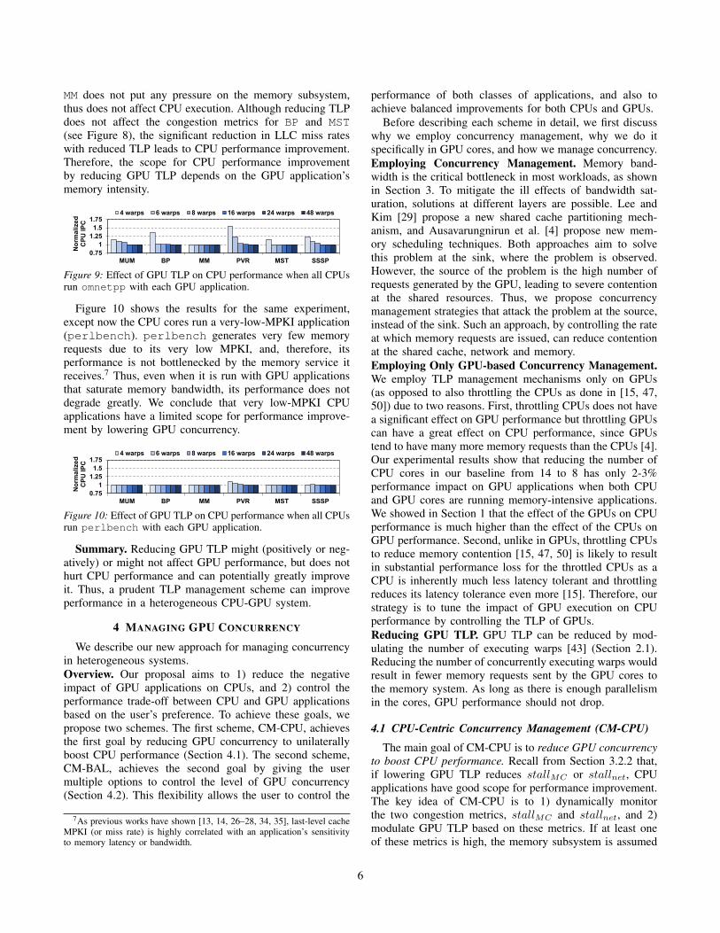
MM does not put any pressure on the memory subsystem,thus does not affect CPU execution. Although reducing TLPdoes not affect the congestion metrics for BP and MST(see Figure 8), the significant reduction in LLC miss rateswith reduced TLP leads to CPU performance improvement.Therefore, the scope for CPU performance improvementby reducing GPU TLP depends on the GPU application’smemory intensity.
0.75
1
1.25
1.5
1.75
MUM BP MM PVR MST SSSP
No
rma
lize
d
CP
U I
PC
4 warps 6 warps 8 warps 16 warps 24 warps 48 warps
Figure 9: Effect of GPU TLP on CPU performance when all CPUsrun omnetpp with each GPU application.
Figure 10 shows the results for the same experiment,except now the CPU cores run a very-low-MPKI application(perlbench). perlbench generates very few memoryrequests due to its very low MPKI, and, therefore, itsperformance is not bottlenecked by the memory service itreceives.7 Thus, even when it is run with GPU applicationsthat saturate memory bandwidth, its performance does notdegrade greatly. We conclude that very low-MPKI CPUapplications have a limited scope for performance improve-ment by lowering GPU concurrency.
0.75
1
1.25
1.5
1.75
MUM BP MM PVR MST SSSP
No
rma
lize
d
CP
U I
PC
4 warps 6 warps 8 warps 16 warps 24 warps 48 warps
Figure 10: Effect of GPU TLP on CPU performance when all CPUsrun perlbench with each GPU application.
Summary. Reducing GPU TLP might (positively or neg-atively) or might not affect GPU performance, but does nothurt CPU performance and can potentially greatly improveit. Thus, a prudent TLP management scheme can improveperformance in a heterogeneous CPU-GPU system.
4 MANAGING GPU CONCURRENCY
We describe our new approach for managing concurrencyin heterogeneous systems.Overview. Our proposal aims to 1) reduce the negativeimpact of GPU applications on CPUs, and 2) control theperformance trade-off between CPU and GPU applicationsbased on the user’s preference. To achieve these goals, wepropose two schemes. The first scheme, CM-CPU, achievesthe first goal by reducing GPU concurrency to unilaterallyboost CPU performance (Section 4.1). The second scheme,CM-BAL, achieves the second goal by giving the usermultiple options to control the level of GPU concurrency(Section 4.2). This flexibility allows the user to control the
7As previous works have shown [13, 14, 26–28, 34, 35], last-level cacheMPKI (or miss rate) is highly correlated with an application’s sensitivityto memory latency or bandwidth.
performance of both classes of applications, and also toachieve balanced improvements for both CPUs and GPUs.
Before describing each scheme in detail, we first discusswhy we employ concurrency management, why we do itspecifically in GPU cores, and how we manage concurrency.Employing Concurrency Management. Memory band-width is the critical bottleneck in most workloads, as shownin Section 3. To mitigate the ill effects of bandwidth sat-uration, solutions at different layers are possible. Lee andKim [29] propose a new shared cache partitioning mech-anism, and Ausavarungnirun et al. [4] propose new mem-ory scheduling techniques. Both approaches aim to solvethis problem at the sink, where the problem is observed.However, the source of the problem is the high number ofrequests generated by the GPU, leading to severe contentionat the shared resources. Thus, we propose concurrencymanagement strategies that attack the problem at the source,instead of the sink. Such an approach, by controlling the rateat which memory requests are issued, can reduce contentionat the shared cache, network and memory.Employing Only GPU-based Concurrency Management.We employ TLP management mechanisms only on GPUs(as opposed to also throttling the CPUs as done in [15, 47,50]) due to two reasons. First, throttling CPUs does not havea significant effect on GPU performance but throttling GPUscan have a great effect on CPU performance, since GPUstend to have many more memory requests than the CPUs [4].Our experimental results show that reducing the number ofCPU cores in our baseline from 14 to 8 has only 2-3%performance impact on GPU applications when both CPUand GPU cores are running memory-intensive applications.We showed in Section 1 that the effect of the GPUs on CPUperformance is much higher than the effect of the CPUs onGPU performance. Second, unlike in GPUs, throttling CPUsto reduce memory contention [15, 47, 50] is likely to resultin substantial performance loss for the throttled CPUs as aCPU is inherently much less latency tolerant and throttlingreduces its latency tolerance even more [15]. Therefore, ourstrategy is to tune the impact of GPU execution on CPUperformance by controlling the TLP of GPUs.Reducing GPU TLP. GPU TLP can be reduced by mod-ulating the number of executing warps [43] (Section 2.1).Reducing the number of concurrently executing warps wouldresult in fewer memory requests sent by the GPU cores tothe memory system. As long as there is enough parallelismin the cores, GPU performance should not drop.
4.1 CPU-Centric Concurrency Management (CM-CPU)
The main goal of CM-CPU is to reduce GPU concurrencyto boost CPU performance. Recall from Section 3.2.2 that,if lowering GPU TLP reduces stallMC or stallnet, CPUapplications have good scope for performance improvement.The key idea of CM-CPU is to 1) dynamically monitorthe two congestion metrics, stallMC and stallnet, and 2)modulate GPU TLP based on these metrics. If at least oneof these metrics is high, the memory subsystem is assumed
6

to be congested either at the MCs or the reply network. Then,we reduce the level of concurrency by reducing the numberof active warps running on GPUs (called, the active warplimit). If both metrics are low, we increase TLP, which mightimprove GPU performance. Otherwise, we keep the activewarp limit unchanged. We use two thresholds, tH and tLto determine if these metrics are low, medium, or high. Weuse a medium range to avoid ping-ponging between differentconcurrency levels. If the active warp limit is between 8 and48, increasing or decreasing concurrency is done in stepsof 2 warps. If the active warp limit is between 1 and 8,the modulation step is 1, because the effect of changingconcurrency is more significant in that range.
Figure 11 shows the architectural diagram of our proposal.To calculate stallMC ( 1 ) and stallnet ( 2 ), we collectthe congestion metrics ( 3 , 4 ) at each memory partitionseparately. A centralized unit, called the CM-CPU logic ( 5 ),periodically (with an interval of 1024 cycles)8 aggregatesthese congestion metrics to calculate stallMC and stallnet,which it compares against tH and tL. Based on the result,it sends the modulation decision to the GPU cores. TheCM-CPU logic is placed next to the global CTA scheduler.The scheduler has a dedicated connection to all the GPUcores [38, 39], and communicates with them frequently. TheCM-CPU logic also needs to communicate with the memorypartitions, where 3 and 4 are calculated, requiring dedicatedconnections with the memory partitions.
CM
-CP
U
logi
c
GTO priority
logic
Ready warps [1:N]
Prioritized warps[1:N]
Warp-limiting scheduler
(SWL)
Warps to be scheduled[1:warp_limit]
N==0
Pipeline register full
Fetch/Decode
I-Buffer/Scoreboard
Warp Issue Arbiter
Registers/Execute
Memory Unit
Fetch/Decode
I-Buffer/Scoreboard
Warp Issue Arbiter
Registers/Execute
Memory Unit
Fetch/Decode
I-Buffer/Scoreboard
Warp Issue Arbiter
Registers/Execute
Memory Unit
GPU cores
Interconnect
CTA
sc
he
du
ler
congestionMC
MC
congestionnet
CPU cores
currentwarp_limit
stallGPU table
1 warp - stallGPU
2 warps - stallGPU
48 warps - stallGPU
…
From CM-CPU logic
CM-BAL logic
LLCLLCLLC
MCMC
congestionMCcongestionMC
congestionnetcongestionnet
stal
l MC
stal
l net
k
10
11
12
34
5
6
7
8
9
13
12
True
Warp Issue Arbiter
Figure 11: Proposed hardware organization. Additional hardwareshown as white components and dashed arrows.
The downside of CM-CPU is that throttling the GPUssolely based on memory/network congestion metrics mighthurt GPU applications that require high TLP for suffi-cient latency tolerance. For such applications, CM-CPU canfail to provide enough latency tolerance due to aggressivethrottling. Because the memory congestion metrics are notcorrelated well with the latency tolerance of the GPU cores,
8We chose an interval of 1024 cycles empirically (but we did not optimizethe value). Such a small interval enables quick adaptation to fast fluctuationsin memory and network congestion.
modifying tH and tL to provide improvements for CPUs aswell as latency tolerance for GPUs is not trivial.
4.2 Balanced Concurrency Management (CM-BAL)
CM-BAL tries to recover the performance of GPU ap-plications that suffer due to insufficient latency toleranceimposed by CM-CPU, up to the extent specified by the user.The key idea of CM-BAL is to: 1) detect whether or notGPU cores have enough latency tolerance, and 2) maintainor increase the number of active warps if GPU coresare not able to hide memory latencies due to insufficientconcurrency. To quantify the latency tolerance of GPU cores,for each core and each monitoring interval, we calculate thenumber of cycles during which the core is not able to issue awarp: stallGPU . We use two warp schedulers per core in ourbaseline, so stallGPU for a core can be between 0 and twicethe number of cycles in an interval. stallGPU is incrementedif there are no ready warps that passed the scoreboard check( 6 ) and the pipeline register for the next stage is full9
( 7 ). CM-BAL logic ( 8 ) calculates the moving average ofstallGPU for each concurrency level in each interval. Thesemoving averages are stored in a table ( 9 ). Depending onthe difference between moving averages of stallGPU of aparticular concurrency level and its neighboring levels, CM-BAL logic either increases or maintains the concurrencylevel ( 10 ). Based on this level, the SWL scheduler ( 11 ) limitsthe number of warps that can be issued to the pipeline.
We observe that the performance difference betweenhigher TLP levels (e.g., between 48 warps and 24 warps,which is negligible in most workloads) is much smaller thanthe performance difference between lower TLP levels. Totake this into account, our algorithm changes the TLP levelnot with fixed steps, but using predetermined levels ( 9 ): 1,2, 3, 4, 6, 8, 16, 24, and 48 warps. We maintain a movingaverage of stallGPU for each of these levels. At the endof an interval, we update the one that has been used duringthat interval. Because during different phases of executionstallGPU for a particular level might have significantlydifferent values, we opted to use moving averages in ordernot to use information coming from only a single intervaland move to a suboptimal level. All moving average entriesare invalidated at the beginning and end of a kernel. A newentry is created for a level with the value of stallGPU of theinterval in which the concurrency level was used for the firsttime. In subsequent intervals during which the same levelis used, CM-BAL logic updates the moving average usingmov avgnew = mov avgold × 0.25 + stallGPU × 0.75.
Figure 12 shows how CM-CPU and CM-BAL work. Thex-axis shows the level of GPU concurrency (TLP), and they-axis denotes stallGPU . This figure illustrates a typicalscenario10 where stallGPU increases with low concurrency,
9This might happen due to instruction latencies and write-back contentionfor ALU instructions, and shared memory bank-conflicts and coalescingstalls for memory instructions.
10This curve does not necessarily have to be parabolic. Its exact shapedepends on the application’s reaction to the variation in TLP.
7

Part 1 of CM-BALPart 2 of CM-BAL
GPU TLP
sta
llG
PU
Lowest TLP that provides enough
latency tolerance
CM-CPU
CM-BAL
R1 R2
CM-CPU’s working domain
1
2
Figure 12: Operation of our schemes. CM-CPU increases/decreasesTLP for all TLP ranges. CM-BAL might use Part 2 to improvelatency tolerance by increasing TLP if TLP is low.
mainly due to low latency tolerance, and increases with highconcurrency, mainly due to high memory contention. R1 isthe region where a GPU application does not have enoughlatency tolerance. R2 is the region where the applicationhas enough latency tolerance, but it might be sufferingfrom memory contention. CM-CPU works on the entireTLP spectrum and increases/decreases concurrency based ontwo congestion metrics, but it does not consider stallGPU .CM-BAL, on the other hand, operates in two parts. Part-1 ( 12 in Figure 11) operates the same way as CM-CPU(with the exception of using concurrency levels, instead offixed steps), and works in R2, as shown in Figure 12. Ifthe application is in R1, Part-2 of CM-BAL overrides anydecision made by CM-CPU, and might increase TLP. Thereare multiple reasons as to why an application moves into R1.First, due to a change in the application’s behavior (the curveshifts on the x-axis), the current TLP point might move intoR1. Second, based on memory contention, CM-CPU mightpush the current TLP point of the application into R1.
We explain how Part-2 of CM-BAL works in R1. This partmakes three decisions. First, as shown in À in Figure 12, ifdecreasing the number of active warps, i.e., moving to theleft on the x-axis, would potentially increase stallGPU bymore than a parameter k ( 13 in Figure 11), i.e., reducingconcurrency might increase stallGPU by more than k, CM-BAL does not allow concurrency to be reduced. Second,as shown in Á in Figure 12, if increasing the number ofactive warps, i.e., moving to the right on the x-axis, wouldpotentially reduce stallGPU by more than k, i.e., increasingconcurrency might decrease stallGPU by more than k, CM-BAL increases concurrency to the next level. In order topredict if changing concurrency would increase/decreasethe value of stallGPU by more than k in either case,CM-BAL logic compares the moving average of stallGPU
of the current level with that of the lower/upper level.11
Third, if the algorithm stays in the same concurrency levelfor 4 consecutive intervals, we increase or decrease TLPif the current concurrency level is less than 6 or greaterthan or equal to 6, respectively (all thresholds empiricallydetermined). We do this to solely update the moving av-erage of stallGPU for neighboring levels as those values
11If the moving average of stallGPU in the lower or upper level isinvalid for this comparison, Part-2 does not override the decision made byPart-1 of CM-BAL.
might become unrepresentative of the current phase of theapplication if not updated.
The higher the k value is, the more difficult it is to im-prove the latency tolerance of GPU cores. Thus, we use thisparameter as a user-controlled knob ( 13 ) to specify the GPUpriority (or, the importance of the GPU relative to the CPU).We provide the user with four different levels of controlfor this knob: CM-BAL1, CM-BAL2, CM-BAL3, and CM-BAL4. CM-BAL1 and CM-BAL4 provide the highest and thelowest GPU performance, respectively. The corresponding kfor each of these four levels is linearly proportional to thenumber of core cycles in an interval. k can take any valuebetween 0 and stallGPU . When k is set to stallGPU , CM-BAL converges to CM-CPU.
5 EXPERIMENTAL METHODOLOGY
Simulated System. Table I provides the configuration detailsof GPU and CPU cores. A GPU core contains 32-wideSIMD lanes and is equipped with an instruction cache,private L1 data cache, constant and texture caches, andshared memory. Each CPU core is a trace-driven, cycle-accurate, 3-issue x86 core; and has a private write-back L1instruction/data and L2 caches. We use a detailed GDDR5DRAM timing model [38].
Table I: Baseline configuration.GPU Core Config. 28 Shader Cores, 1400MHz, SIMT Width = 16 × 2GPU Resources / Core Max.1536 Threads (48 warps, 32 threads/warp),
48KB Shared Memory, 32684 RegistersGPU Caches / Core 16KB 4-way L1 Data Cache, 12KB 24-way Texture,
8KB 2-way Constant Cache, 2KB 4-way I-cache,128B Line Size
CPU Core Config. 14 x86 Cores, 2000MHz,128-entry instruction window, OoO Fetch and Execute3 instructions/cycle, max. 1 memory instruction/cycle
CPU L1 Cache / Core 32KB 4-way, 2-cycle lookup, 128B Line SizeCPU L2 Cache / Core 256KB 8-way, 8-cycle lookup, 128B Line SizeShared LLC Cache 1 MB/Memory Partition, 128B Line, 16-way, 700MHzDefault Warp Scheduler Greedy-then-oldest [43]Features Memory Coalescing, Inter-warp Merging,
Post DominatorInterconnect 6 × 6 Shared 2D Mesh, 1400MHz, XY Routing,
2 GPU cores per node, 1 CPU core per node,32B Channel Width, 4VCs, Buffers/VC = 4
Memory Model 8 Shared GDDR5 MCs, 800 MHz,FR-FCFS [42, 51], 8 DRAM-banks/MC
GDDR5 Timing tCL=12, tRP=12, tRC=40, tRAS=28, tCCD=2,tRCD=12, tRRD=6, tCDLR=5, tWR=12
Evaluation Methodology. To evaluate our proposal, weintegrated GPGPU-Sim v3.2.0 [5] with an in-house cycle-level x86 CMP simulator. The simulation starts with CPUexecution. After the slowest CPU core warms up with500K instructions, GPU execution starts. To measure CPUperformance, we run until the slowest core reaches 5 millioninstructions. To measure GPU performance, we run theapplication until completion or 100 million instructions,whichever comes first.Application Suites for GPUs and Benchmarks for CPUs.
We evaluate a wide range of applications for GPUs andCPUs. Our repertoire of 13 GPU applications, shown inTable II, come from Rodinia [9], Parboil [46], MapRe-duce [17], the CUDA SDK [5] and LonestarGPU [7]. Weclassify these applications into three categories based on
8

their optimal TLP. The applications that perform the bestwith higher TLP values belong to Type-H, and they havehigh latency tolerance. The applications that perform thebest with lower TLP values due to lower congestion andbetter cache performance belong to Type-L. The remainingapplications that are mostly insensitive to TLP belong toType-M. The CPU applications we use include scientific,commercial, and desktop applications drawn from the SPECCPU 2000/2006 INT and FP suites and commercial serverworkloads. We choose representative execution phases fromthese applications using PinPoints [33]. We classify the CPUapplications into three types based on their LLC misses-per-kilo-instruction (MPKI) rates, as shown in Table III.
Table II: GPU applications: Type-H: Applications that benefit fromhigher TLP. Type-M: Applications that are mostly insensitive toTLP. Type-L: Applications that benefit from lower TLP. OptimalTLP (Opt. TLP) is given in number of warps.
# Suite Application Abbr. Type Opt. TLP1 Rodinia Backpropagation BP Type-H 482 Rodinia Hotspot HOT Type-H 16-483 Rodinia Pathfinder PATH Type-H 484 Parboil Matrix Mult. MM Type-H 16-485 CUDA SDK BlackScholes BLK Type-M 166 MapReduce Page View Count PVC Type-M 87 MapReduce Page View Rank PVR Type-M 88 LonestarGPU Breadth-First Src. BFS Type-M 69 LonestarGPU Min. Span. Tree MST Type-M 810 CUDA SDK MUMerGPU MUM Type-L 411 MapReduce InvertedIndex IIX Type-L 112 LonestarGPU Single-Source SP Type-L 4
Shortest Paths13 LonestarGPU Survey Propagation SSSP Type-L 6
Table III: CPU applications: L2 MPKI and classification# App. L2 MPKI Type1 perlbench 0.2 L-MPKI2 povray 0.2 L-MPKI3 tonto 0.2 L-MPKI4 applu 0.3 L-MPKI5 calculix 0.3 L-MPKI6 gcc 0.3 L-MPKI7 namd 0.4 L-MPKI8 barnes 0.7 L-MPKI9 gromacs 0.7 L-MPKI
10 sjeng 0.8 L-MPKI11 dealII 1 L-MPKI12 wrf 1.3 L-MPKI13 h264ref 1.5 L-MPKI14 cactus 1.6 L-MPKI15 gobmk 1.6 L-MPKI16 bzip2 3.1 M-MPKI17 sjas 4 M-MPKI
# App. L2 MPKI Type18 tpcw 4.8 M-MPKI19 Gems 5.2 M-MPKI20 hmmer 7 M-MPKI21 astar 7.1 M-MPKI22 sjbb 7.5 M-MPKI23 swim 10 M-MPKI24 ocean 10.6 M-MPKI25 sphinx3 12 M-MPKI26 libquantum 12.5 M-MPKI27 art 13.6 M-MPKI28 lbm 14 M-MPKI29 leslie3d 14.2 M-MPKI30 xalan 14.6 M-MPKI31 milc 25 H-MPKI32 omnetpp 25.8 H-MPKI33 mcf 49.8 H-MPKI34 soplex 103.2 H-MPKI
Workloads. From the three CPU application types, we formtwo CPU mixes per type,12 listed in Table IV. Each of thesemixes are then coupled with a GPU application to form aworkload. The GPU application is chosen in such a waythat each CPU mix gets paired with two randomly chosenGPU applications from each of the three GPU applicationtypes. Thus, we have six workloads for each CPU mix, fora total of 36 workloads. These workloads cover all possiblecombinations of CPU and GPU application types; 3 CPU
12We limited the number of CPU mixes because we found that thebehavior of the mixes that belong to the same category are similar.
and 3 GPU application types form 9 workload types (e.g.,Type-H/L-MPKI), and 4 workloads for each workload type.
Table IV: List of CPU workloads (application mixes).
CPU Mix Applications in the mixL1 povray, tonto, applu, calculix, gcc, namd, barnes, gromacs,
sjeng, dealII, wrf, h264ref, cactusADM, gobmkL2 sjeng, dealII, wrf, h264ref, cactusADM, gobmk, sjeng,
dealII, wrf, h264ref, cactusADM, gobmk, sjeng, dealIIM1 sjas, tpcw, Gems, hmmer, astar, sjbb, swim, ocean, sphinx3,
libquantum, art, lbm, leslie3d, xalanM2 ocean, sphinx3, libquantum, art, lbm, leslie3d, xalan, ocean,
sphinx3, libquantum, art, lbm, leslie3d, xalanH1 milc, soplex, milc, omnetpp, mcf, soplex, milc, omnetpp,
mcf, soplex, mcf, soplex, omnetpp, mcfH2 omnetpp, omnetpp, omnetpp, omnetpp, omnetpp, milc, milc,
milc, milc, milc, soplex, soplex, mcf, mcf
Performance Metrics.. To capture GPU performance, weuse GPU speedup (SUGPU ), which is the ratio of itsinstructions-per-cycle (IPC) when it runs along with CPUto its IPC when it runs alone. We use weighted speedupto capture CPU performance (WSCPU ) [44]. WSCPU is
defined asn∑
i=1
(IPCi,multiprogram/IPCi,alone), where n is
the number of CPU applications in the workload. All averagespeedup results in the paper use harmonic mean. Based onuser preferences, one might want to change the importancegiven to CPU or GPU when calculating speedup [4]. For thisreason, we use the overall system speedup (OSS) metric [4]:OSS = (1 − α) × WSCPU + α × SUGPU , where α isa number between 0 and 1. A higher α indicates higherGPU importance. Note that α is only an evaluation metricparameter, not an input to our schemes.Mechanism Parameters. k is a user-dependent parameterto specify the relative importance of GPU vs. CPU. Ahigh value of k places less importance on the GPU. In ourevaluations, we use four values for k: 32 (CM-BAL1), 64(CM-BAL2), 96 (CM-BAL3), 128 (CM-BAL4). To achievebalanced improvements for both the CPU and the GPU, theuser can set k to 32 (called the CM-BAL1 configuration).Mechanism Thresholds. We use 1 and 0.25 for tH and tL,respectively. These thresholds are determined empirically,and they correlate well with their effect on CPU applica-tions’ performance, as given in Figure 8. These thresholdsalso correlate well with the memory bandwidth saturationand reply network saturation, as memory access latenciesstart to increase non-linearly beyond the high thresholdcongestion range identified by these thresholds. Monitoringinterval is set to 1024 cycles. The thresholds require cali-bration for different system designs.Hardware Overhead. As shown in Figure 11, in each core,the warp scheduler requires a table ( 9 in Figure 11) with 99-bits13, a 6-bit register ( 10 ), and a comparator ( 6 ). CM-BALlogic ( 8 ) requires two 10-bit adders and two shift registers.The CTA scheduler ( 5 ) requires two 13-bit counters and twoadders to calculate/store the congestion metrics, two 13-bit
13There are nine entries in the table. Each entry requires 11 bits becauseit is incremented by two warp schedulers during a 1024-cycle interval.
9

registers to hold the congestion thresholds, and four com-parators for the CM-CPU decision. Each memory partition( 3 , 4 ) requires two 10-bit counters to sample the congestionmetrics. As such, the total storage cost of our proposal is16 bytes per GPU core, 3 bytes per memory partition, and8 bytes for the CTA scheduler.
6 EXPERIMENTAL RESULTS
6.1 Dynamism of ConcurrencyWe first analyze the effect of our techniques on GPU
concurrency with two studies. First, Figure 13 shows theaverage number of active warps on GPU cores during thecourse of execution. Figure 13a shows the concurrencybehavior of a Type-H GPU application (PATH) when it isexecuted alongside two different CPU mixes (L1 and H1),with CM-CPU. Because higher MPKI CPU applicationsexert more pressure on the memory system than lower MPKIapplications, and because CM-CPU decisions are basedsolely on congestion metrics, the number of active warps islower when a GPU application is executed alongside higherMPKI applications. This causes CM-CPU to hurt the per-formance of Type-H GPU applications when boosting CPUperformance. Figure 13b shows that the TLP in CM-BAL1
is higher than in CM-CPU for the same workloads (exceptfor sudden drops from 48 to 24 warps with the L-MPKIworkload because there are no concurrency levels between24 and 48 warps). As expected, L-MPKI CPU workloadslead to higher TLP compared to H-MPKI workloads. Weobserved similar behavior for Type-M and Type-L GPUapplications when run with L- and H-MPKI CPU mixes.
0
8
16
24
32
40
48
Avera
ge #
of
acti
ve
warp
s
Time
L-MPKI (L1) H-MPKI (H1)
(a) PATH with CM-CPU.
0
8
16
24
32
40
48
Avera
ge #
of
acti
ve
warp
s
Time
L-MPKI (L1) H-MPKI (H1)
(b) PATH with CM-BAL1.Figure 13: Average number of active warps over time.
Second, Figure 14 provides insight into the working ofCM-BAL by showing the relationship between the metricsmonitored by CM-BAL and the number of active warps ona core, over a short period of time, in one of our work-loads (Type-L/H-MPKI – MUM/H1). In this plot, difflow= (stallGPU of the lower concurrency level − stallGPU
of the current concurrency level); and diffup = (stallGPU
of the current concurrency level − stallGPU of the upperconcurrency level). If difflow > k, CM-BAL does notreduce the GPU TLP. If diffup > k, CM-BAL increasesthe GPU TLP (see Section 4.2). At A , since diffup > k,the number of warps is increased for the next interval. Thisworkload stresses the memory, leading to high stallMC . Asa result, at B , Part-1 of CM-BAL wants to reduce TLP.However, because difflow > k (i.e., reducing TLP wouldlikely lead to increased GPU stall time), Part-2 of CM-BALkicks in, and TLP is not reduced. In contrast, a similar
scenario at C leads to lower TLP in the next interval,because the concurrency level has remained unchanged forthe past 4 consecutive intervals. At D , Part-1 of CM-BALreduces TLP because diffup < k, and difflow < k. Thisexample shows that CM-BAL effectively adapts concurrencyto dynamic workload behavior at fine granularity.
A B C D
-4000
-2000
0
2000
4000
0
4
8
12
16
Cyc
les
The
nu
mb
er
of
acti
ve w
arp
s
Time
# of warps diff_low diff_up k
B CDA
Figure 14: Number of active warps over time with CM-BAL.difflow, diffup, and k are shown in the secondary y-axis.
Figure 15 shows the average number of warps in a GPUcore across nine workload types, with CM-CPU and CM-BAL1. As expected, CM-CPU reduces concurrency veryaggressively. CM-BAL1 maintains high TLP for Type-Happlications, low TLP for Type-L applications, and reducesTLP of Type-M applications as much as possible withouthurting them. Hence, our techniques effectively modulateGPU concurrency in an application-aware manner.
08
1624324048
Type-H/ L-
MPKI
Type-H/ M-
MPKI
Type-H/ H-
MPKI
Type-M/ L-
MPKI
Type-M/ M-
MPKI
Type-M/ H-
MPKI
Type-L/ L-
MPKI
Type-L/ M-
MPKI
Type-L/ H-
MPKI
Ave
rag
e #
of
ac
tive
wa
rps
CM-CPU
CM-BAL1
Figure 15: Average number of warps with CM-BAL1.
6.2 Application Performance ResultsFigure 16 shows the average performance of GPU ap-
plications obtained by our schemes for all workload types.The results are normalized to the performance of the sameworkloads when they are executed using the baseline warpscheduler, GTO. We also evaluate DYNCTA after tuning itsparameters. We make several observations. First, DYNCTAworks only for Type-L applications, and improves theirperformance by 7%, while not hurting any workload bymore than 2%. Second, CM-CPU causes significant per-formance losses in Type-H and Type-M applications, asthose applications require high latency tolerance and CM-CPU is aware only of memory congestion, not the latencytolerance of GPU cores. However, CM-CPU improves theperformance of Type-L applications due to successful con-gestion management. We observe high benefits for Type-L/L-MPKI workloads due to two workloads that run IIX.IIX prefers 1-2 active warps, but its CTAs have more warps.Because DYNCTA manages the TLP at the CTA level, itcannot reduce concurrency as much CM-CPU can. Third,CM-BAL1, recovers the losses caused by CM-CPU forType-H and Type-M applications by providing more latencytolerance. As a result, the worst performing GPU application
10
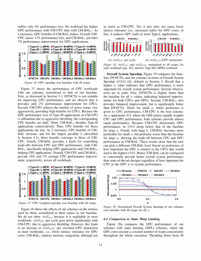
suffers only 4% performance loss. No workload has higherGPU performance with CM-CPU than with CM-BAL1. Ask increases, GPU benefits of CM-BAL reduce. Overall, CM-CPU causes 11% performance loss, and CM-BAL1 provides7% performance improvement for GPU applications.
0
0.5
1
1.5
DYNCTA CM-CPU CM-BAL1 CM-BAL2 CM-BAL3 CM-BAL4
No
rma
lıze
d G
PU
IP
C
Type-H / L-MPKI Type-H / M-MPKI Type-H / H-MPKIType-M / L-MPKI Type-M / M-MPKI Type-M / H-MPKIType-L / L-MPKI Type-L / M-MPKI Type-L / H-MPKI
Figure 16: GPU speedup over baseline with 48 warps.
Figure 17 shows the performance of CPU workloadswith our schemes, normalized to that of our baseline.First, as discussed in Section 3.1, DYNCTA is not suitablefor improving CPU performance, and we observe that itprovides only 2% performance improvement for CPUs.Second, CM-CPU reduces the number of active warps veryaggressively, providing high benefits for CPUs. Because theGPU performance loss of Type-M applications in CM-CPUis substantial due to aggressive throttling, the correspondingCPU benefits are high. Third, CM-BAL1 throttles Type-Happlications conservatively. Thus, CPU benefits for thoseapplications are low. As k increases, CPU benefits of CM-BAL increase, and for the largest possible k (describedin Section 4.2), these benefits converge to those of CM-CPU. Fourth, CM-BAL provides a knob for controllingtrade-offs between CPU and GPU performance, with CM-BAL1 specifically helping GPU applications and CM-BAL4
helping CPU applications. Overall, CM-CPU and CM-BAL1
provide 24% and 7% average CPU performance improve-ment, respectively, across all workloads.
0
0.5
1
1.5
DYNCTA CM-CPU CM-BAL1 CM-BAL2 CM-BAL3 CM-BAL4
No
rma
lıze
d C
PU
WS
Type-H / L-MPKI Type-H / M-MPKI Type-H / H-MPKIType-M / L-MPKI Type-M / M-MPKI Type-M / H-MPKIType-L / L-MPKI Type-L / M-MPKI Type-L / H-MPKI
Figure 17: CPU weighted speedup over baseline with 48 warps.
Figure 18 shows the effects of our schemes on the metricsused by them, normalized to their values in our baseline.We do not show stallnet because it is negligible in mostworkloads. stallMC per cycle goes down significantly withCM-CPU, due to aggressive throttling. However, this leadsto an increase in stallGPU per executed GPU instructionin most workloads, i.e., lower latency tolerance for GPUcores. CM-BAL1 reduces memory congestion, although not
as much as CM-CPU. Yet, it also does not cause lowerlatency tolerance (i.e., increased stalls) for GPU cores; infact, it reduces GPU stalls in most Type-L applications.
00.20.40.60.8
11.2
No
rma
lize
d
sta
llM
C/c
ycle
CM-CPU CM-BAL1
(a) stallMC per cycle.
00.20.40.60.8
11.21.4
No
rmali
ze
d
sta
llG
PU/i
ns
t.
CM-CPU CM-BAL1
(b) stallGPU /GPU instruction.
Figure 18: stallMC and stallGPU normalized to 48 warps, foreach workload type. H-L denotes Type-H/L-MPKI workload.
Overall System Speedup. Figure 19 compares the base-line, DYNCTA, and our schemes in terms of Overall SystemSpeedup (OSS) [4], defined in Section 5. Recall that ahigher α value indicates that GPU performance is moreimportant for overall system performance. Several observa-tions are in order. First, DYNCTA is slightly better thanthe baseline for all α values, indicating balanced improve-ments for both CPUs and GPUs. Second, CM-BAL1 alsoprovides balanced improvement, but is significantly betterthan DYNCTA. Third, for small α, where preference isgiven to CPU performance, CM-CPU is the best scheme.As α approaches 0.5, where the OSS metric equally weightsCPU and GPU performance, both schemes provide almostequal performance. Because CM-CPU deteriorates GPUperformance, its OSS drops below that of the baselinefor large α. Fourth, with large k, CM-BAL becomes morepreferable for small α, but performs worse than the baselinefor large α, showing the trade-off between CPU and GPUperformance in CM-BAL. These results show that the usercan pick a different CM-BAL level (based on preference ofhow important the GPU is relative to the CPU) that wouldlead to the highest OSS. Hence, CM-BAL can be configuredto consistently provide better overall system performancethan state-of-the-art designs regardless of how important theCPU or the GPU is to system performance.
0.875
1
1.125
1.25
0.0 0.5 1.0
No
rmal
ize
d O
SS(α
)
α
48 warps DYNCTA CM-CPU CM-BAL1
CM-BAL2 CM-BAL3 CM-BAL4
Figure 19: Normalized Overall System Speedup of our schemesover baseline with 48 warps for all α.
6.3 Comparison to Static Warp LimitingFigure 20a compares the GPU performance of our
schemes with static limiting (SWL) schemes, where theGPU cores execute a constant number of warps concurrentlythroughout the whole execution. Throttling down from 48
11

0
0.5
1
1.5
No
rmali
zed
GP
U IP
C Type-H Type-M Type-L
(a) GPU performance.
0
0.5
1
1.5
2
No
rmali
zed
CP
U I
PC L-MPKI M-MPKI H-MPKI
(b) CPU performance.Figure 20: Our schemes vs. static warp limiting. Performancecomparisons are clustered based on GPU/CPU application types.
warps to 4 causes performance loss for Type-H applications,improves Type-L applications, and does not affect Type-M applications. Further throttling hurts GPU applicationssignificantly. CM-BAL1 provides better performance forGPUs compared to all static warp limits. Figure 20b showsthe effect of static warp throttling on CPU performance.Although limiting the number of warps to 4 or 6 benefitsCPU performance, this comes at the expense of significantGPU performance degradation.14 We conclude that staticwarp throttling cannot enable flexible performance trade-offbetween the CPU and the GPU and optimization of overallsystem performance as CM-BAL does (Section 6.2).
6.4 Sensitivity Experiments
Scalability. Our scalability analysis shows that varying thenumber of GPU cores in a tile between 2, 4 (default), and6 shows minimal change in performance benefits of ourtechniques. We also evaluated a smaller and less power-hungry system with 4 GPU cores, 3 CPU cores, and 2 MCsconnected via a 3× 3 mesh. This configuration is closer tocurrently available systems in terms of the number of cores.CM-BAL1 provides 13% and 2% average CPU and GPUperformance improvement, respectively, on this system, evenwith unoptimized thresholds.Partitioned vs. Shared Resources. We evaluated CM-BAL1 using a partitioned network and shared MCs. On thisbaseline, which performs significantly worse than the sharednetwork-shared MC baseline (Section 2.2), CM-BAL1 pro-vides 15% GPU and 8% CPU performance improvement.
6.5 Other Analyses and Discussion
LLC Contention. Our mechanisms reduce LLC contentionmainly due to two reasons. First, TLP management reducesthe rate at which memory requests are issued from GPUcores. Second, TLP management reduces L1 miss rates,leading to fewer LLC accesses. Overall, we observe thatCM-BAL1 reduces the number of LLC accesses by 13%.Power Consumption. Recent works [16, 45] show thatconcurrency management in GPUs not only improves per-formance but also increases energy-efficiency for memory-intensive applications. Thus, we expect our schemes toimprove energy-efficiency for memory-intensive workloads,and not reduce it for compute-intensive workloads.
14At the extreme case, completely disabling GPU execution leads to 69%higher CPU performance over the baseline.
Effect of GPU Aggressiveness. Although we evaluate ourproposal with a Fermi-like GPU model (Section 5), we alsoexpect to observe benefits in newer architectures, due toincreased TLP and increased contention for shared memoryresources. For example, in the newer NVIDIA Kepler [39]:1) GPU cores have more processing elements, leading tomore GPU TLP, 2) L1 cache capacity is the same asFermi [38], leading to higher cache contention, 3) GDDR5memory bandwidth [1] has not increased proportionallywith core count, leading to higher memory contention. Weenvision that these three factors, which indicate trends inGPU platform design, will make concurrency managementeven more important in newer and future architectures.
7 RELATED WORK
When CPU and GPU applications are co-scheduled on thesame hardware, they interfere with each other in the sharedresources. In this context, we discuss the prior works thataddress such interference at various points in the hierarchy.Managing Interference at NoC, Caches, and Memory.Lee et al. characterize network contention [31] and proposevirtual channel partitioning [30] to mitigate it. Ausavarung-nirun et al. [4] propose a memory scheduling design that re-duces the interference of CPU and GPU applications. Jeonget al. [19] provide a mechanism that provides QoS for GPUapplications in a CPU-GPU system by aptly prioritizingrequests at the MCs. Lee and Kim [29] observe interferencebetween CPU and GPU applications at the LLC, and proposecache management techniques that also consider TLP ofGPU applications. Jog et al. [21] propose a simple round-robin memory scheduler for reducing contention caused bymultiple GPU applications. The focus of all these works is tohandle the application interference at only one of the levelsof the memory hierarchy. In contrast, we show that GPUscreate interference to CPUs at all parts of the shared memoryhierarchy. To address this interference, we modulate the TLPof GPU applications by considering system-wide congestionmetrics and GPU latency tolerance.Managing Interference from the Core. Kayiran et al. [24]and Rogers et al. [43] modulate TLP in GPUs to reducecontention in the memory system and L1 caches, respec-tively. Jog et al. [22, 23] propose warp scheduling techniquesto address contention in GPU caches and memory. Manysource throttling schemes [8, 10, 15, 40, 41, 48] are proposedin the context of CPUs to address congestion in NoCs andmemory. None of these works are designed or evaluated forCPU-GPU architectures. To our knowledge, this is the firstwork that uses source throttling to 1) to control interferencebetween both CPU and GPU applications, and 2) to reduceinterference both at the NoCs and main memory in aheterogeneous CPU-GPU system.
8 CONCLUSIONS
TLP management in GPUs is essential in hybrid CPU-GPU environments with shared resources to maximize over-all system throughput. In this paper, we introduce a newGPU concurrency throttling strategy that tunes the impact
12

of GPU applications on both CPU applications and systemperformance. Our strategy takes into account both system-wide memory/network congestion and GPU latency toler-ance to dynamically decide the level of GPU concurrency.We propose two different implementations of our strategy: 1)to boost the performance of CPUs, and 2) to flexibly improveoverall system performance based on the user’s preferencefor higher CPU or GPU performance. Experimental eval-uations show that the first scheme significantly improvesaverage CPU performance, but causes some GPU perfor-mance loss. The tunable second scheme, when configured toimprove CPU and GPU performance in a balanced manner,provides 7% performance benefit for both CPU and GPUapplications, without significantly hurting any workload’sperformance. We conclude that our GPU TLP managementframework provides a flexible and efficient substrate tomaximize system performance and control CPU-GPU per-formance trade-offs in modern heterogeneous architectures.
ACKNOWLEDGMENTS
We thank the anonymous reviewers for their valuablefeedback. This research is supported in part by NSF grants#1212962, #1205618, #1213052, #1302225, #1302557,#1317560, #1320478, #1409095, #1439021, #1439057,#1409723, the Intel Science and Technology Center onCloud Computing, SRC and Intel.
REFERENCES
[1] G. Abbas. (2012) NVIDIA CUDA: Kepler vs.Fermi Architecture. Available: http://blog.cuvilib.com/2012/03/28/nvidia-cuda-kepler-vs-fermi-architecture/
[2] Advanced Micro Devices, Inc. (2013) What is HeterogeneousSystem Architecture (HSA)? Available: http://www.amd.com/en-gb/innovations/software-technologies/hsa
[3] AMD. (2014) Compute Cores. Available: http://www.amd.com/Documents/Compute Cores Whitepaper.pdf
[4] R. Ausavarungnirun et al., “Staged Memory Scheduling: AchievingHigh Prformance and Scalability in Heterogeneous Systems,” in ISCA,2012.
[5] A. Bakhoda et al., “Analyzing CUDA Workloads Using a DetailedGPU Simulator,” in ISPASS, 2009.
[6] A. Bakhoda et al., “Throughput-effective On-chip Networks forManycore Accelerators,” in MICRO, 2010.
[7] M. Burtscher et al., “A Quantitative Study of Irregular Programs onGPUs,” in IISWC, 2012.
[8] K. K.-W. Chang et al., “HAT: Heterogeneous Adaptive Throttling forOn-Chip Networks,” in SBAC-PAD, 2012.
[9] S. Che et al., “Rodinia: A Benchmark Suite for HeterogeneousComputing,” in IISWC, 2009.
[10] H. Cheng et al., “Memory Latency Reduction via Thread Throttling,”in MICRO, 2010.
[11] W. Dally, “GPU Computing to Exascale and Beyond,” in SC, 2010.[12] W. Dally and B. Towles, Principles and Practices of Interconnection
Networks. Morgan Kaufmann, 2003.[13] R. Das et al., “Application-to-core Mapping Policies to Reduce
Memory System Interference in Multi-core Systems,” in HPCA, 2013.[14] R. Das et al., “Application-aware prioritization mechanisms for on-
chip networks,” in MICRO, 2009.[15] E. Ebrahimi et al., “Fairness via Source Throttling: A Configurable
and High-performance Fairness Substrate for Multi-core MemorySystems,” in ASPLOS, 2010.
[16] M. Gebhart et al., “Energy-efficient Mechanisms for ManagingThread Context in Throughput Processors,” in ISCA, 2011.
[17] B. He et al., “Mars: A MapReduce Framework on Graphics Proces-sors,” in PACT, 2008.
[18] Intel. (2012) Products (Formerly Ivy Bridge). Available: http://ark.intel.com/products/codename/29902/
[19] M. K. Jeong et al., “A QoS-aware Memory Controller for Dynam-ically Balancing GPU and CPU Bandwidth Use in an MPSoC,” inDAC, 2012.
[20] M. K. Jeong et al., “Balancing DRAM Locality and Parallelism inShared Memory CMP Systems,” in HPCA, 2012.
[21] A. Jog et al., “Application-aware Memory System for Fair andEfficient Execution of Concurrent GPGPU Applications,” in GPGPU,2014.
[22] A. Jog et al., “Orchestrated Scheduling and Prefetching for GPGPUs,”in ISCA, 2013.
[23] A. Jog et al., “OWL: Cooperative Thread Array Aware SchedulingTechniques for Improving GPGPU Performance,” in ASPLOS, 2013.
[24] O. Kayiran et al., “Neither More Nor Less: Optimizing Thread-levelParallelism for GPGPUs,” in PACT, 2013.
[25] Khronos OpenCL Working Group, “The OpenCL Specification,”2008.
[26] Y. Kim et al., “ATLAS: A Scalable and High-Performance SchedulingAlgorithm for Multiple Memory Controllers,” in HPCA, 2010.
[27] Y. Kim et al., “Thread Cluster Memory Scheduling: ExploitingDifferences in Memory Access Behavior,” in MICRO, 2010.
[28] C. J. Lee et al., “Improving Memory Bank-Level Parallelism in thePresence of Prefetching” ,” in MICRO, 2009.
[29] J. Lee and H. Kim, “TAP: A TLP-aware Cache Management Policyfor a CPU-GPU Heterogeneous Architecture,” in HPCA, 2012.
[30] J. Lee et al., “Adaptive Virtual Channel Partitioning for Network-on-chip in Heterogeneous Architectures,” ACM TODAES, 2013.
[31] J. Lee et al., “Design Space Exploration of On-chip Ring Intercon-nection for a CPU-GPU Heterogeneous Architecture,” JPDC, 2013.
[32] E. Lindholm et al., “NVIDIA Tesla: A Unified Graphics and Com-puting Architecture,” Micro, IEEE, vol. 28, no. 2, 2008.
[33] C.-K. Luk et al., “Pin: Building Customized Program Analysis Toolswith Dynamic Instrumentation,” in PLDI, 2005.
[34] A. K. Mishra et al., “A Heterogeneous Multiple Network-on-chipDesign: An Application-aware Approach,” in DAC, 2013.
[35] S. P. Muralidhara et al., “Reducing Memory Interference in MulticoreSystems via Application-aware Memory Channel Partitioning,” inMICRO, 2011.
[36] V. Narasiman et al., “Improving GPU Performance via Large Warpsand Two-level Warp Scheduling,” in MICRO, 2011.
[37] NVIDIA. (2011) CUDA C/C++ SDK Code Samples. Available:http://developer.nvidia.com/cuda-cc-sdk-code-samples
[38] NVIDIA. (2011) Fermi: NVIDIA’s Next Gen-eration CUDA Compute Architecture. Available:http://www.nvidia.com/content/PDF/fermi white papers/NVIDIAFermi Compute Architecture Whitepaper.pdf
[39] NVIDIA. (2012) NVIDIA’s Next Generation CUDA Compute Ar-chitecture: Kepler GK110. Available: http://www.nvidia.com/content/PDF/kepler/NVIDIA-Kepler-GK110-Architecture-Whitepaper.pdf
[40] G. Nychis et al., “Next Generation On-Chip Networks: What Kindof Congestion Control Do We Need?” in Hotnets, 2010.
[41] G. Nychis et al., “On-chip Networks from a Networking Perspective:Congestion and Scalability in Many-core Interconnects,” in SIG-COMM, 2012.
[42] S. Rixner et al., “Memory Access Scheduling,” in ISCA, 2000.[43] T. G. Rogers et al., “Cache-Conscious Wavefront Scheduling,” in
MICRO, 2012.[44] A. Snavely and D. M. Tullsen, “Symbiotic Jobscheduling for a
Simultaneous Multithreaded Processor,” in ASPLOS, 2000.[45] S. Song et al., “Energy-efficient Scheduling for Memory-intensive
GPGPU Workloads,” in DATE, 2014.[46] J. A. Stratton et al., “Parboil: A Revised Benchmark Suite for
Scientific and Commercial Throughput Computing,” Univ. of Illinois,Tech. Rep. IMPACT-12-01, March 2012.
[47] M. A. Suleman et al., “Feedback-driven Threading: Power-efficientand High-performance Execution of Multi-threaded Workloads onCMPs,” in ASPLOS, 2008.
[48] M. Thottethodi et al., “Self-Tuned Congestion Control for Multipro-cessor Networks,” in HPCA, 2001.
[49] M. Xie et al., “Improving System Throughput and Fairness Si-multaneously in Shared Memory CMP Systems via Dynamic BankPartitioning,” in HPCA, 2014.
[50] X. Zhang et al., “Hardware Execution Throttling for Multi-coreResource Management,” in USENIX, 2009.
[51] W. K. Zuravleff and T. Robinson, “Controller for a SynchronousDRAM that Maximizes Throughput by Allowing Memory Requestsand Commands to be Issued Out of Order,” Patent U.S. 5,630,096,1997.
13