Embed Size (px)
Citation preview

1
Management of Correctness Problems in UML Class Diagrams – Towards a Pattern-based Approach∗
Mira Balaban
Department of Computer Science Ben-Gurion University of the Negev, Beer Sheva 84105, Israel
Azzam Maraee
Department of Computer Science, Ben-Gurion University of the Negev, Beer Sheva 84105, Israel
Arnon Sturm+
Department of Information Systems Engineering, Ben-Gurion University of the Negev, Beer Sheva 84105, Israel
ABSTRACT UML is now widely accepted as the standard modeling language for software construction. The
Class Diagram is its core view, having well formed semantics and providing the backbone for
any modeling effort. Class diagrams are widely used for purposes such as software specification,
database and ontology engineering, meta-modeling, and model transformation. The central role
played by class diagrams emphasizes the need for strengthening UML modeling tools with
features such as recognition of erroneous models and the detection of errors’ sources.
Correctness of UML class diagrams refers to the capability of a diagram to denote a finite but not
empty reality. This is a natural, unquestionable requirement. Nevertheless, incorrect diagrams
are often designed, due to the interaction of contradicting constraints and the limitations of
current tools. In this paper we clarify the notion of class diagram correctness, discuss various
approaches for detecting correctness problems, and propose a pattern-based approach for
∗ This work was supported in part by the Paul Ivanir Center for Robotics and Production Management at Ben- Gurion University of the Negev. + Corresponding Author

2
identifying situations in which correctness problems occur, and for providing explanations and
repair advices.
Keywords: Modeling Languages, incorrectness patterns, UML class diagrams, consistency, finite
satisfiability, redundancy, incomplete design, reasoning, detection, identification, model driven
engineering
INTRODUCTION The Unified Modeling Language (UML) is the de facto standard for system development, as it
was developed and adopted by the Object Management Group (OMG-UML, 2009). It consists of
several diagrammatic languages, each describing a different view of object-oriented software; a
system model consists of a collection of such diagrams. The most important view of UML is the
static/structural specification which describes a structural abstraction of the real world. This view
is expressed by class diagrams, which consist of classes and their descriptors, associations
among them, and constraints imposed on both classes and associations. Among the nine visual
UML models, class diagrams appear to be the most clear, intuitive and well defined.
Dobing and Parsons (2006) found that the Class Diagram view is the most frequently used
(73%) in their examination of the usage of UML. It was found to be useful in clarifying technical
understanding, and for maintaining software documentation. The major usage of UML class
diagrams is to specify, visualize, and document systems’ static view. They also serve as a basis
for generating implementation artifacts such as code skeleton (Martin, 2006) and database
schemata (Blaha et al., 1994), as a means for knowledge representation such as specifying
ontologies (Cranefield, 2001; Falkovych et al., 2003; Gasevic et al. 2004; Kabilan &
Johannesson, 2004; Kogut, 2002; Timm & Gannod, 2005), and for defining meta-models of
other programming, modeling, and specification languages.
Class diagrams are models written by people, and therefore, usually suffer from modeling
problems like inconsistency, redundancy, and abstraction errors. Inexperienced designers tend
to create erroneous models, but even experienced ones cannot anticipate the implication of a
change on an overall model (Sunye et al., 2001). Indeed, Lange et al. (2006) show that model
defects often remain undetected, even if practitioners check the model attentively. These

3
problems are empowered when a model originates from different resources. Combined sources
are usually overlapping, and the integration yields redundant inconsistent models (Ackermann &
Turowski, 2006; Huzar et al., 2004). It is a common belief that such problems can best be solved
at the level of models (Jackson & Rinard, 2004).
In view of the wide spread usage of UML class diagrams and the difficulties of producing
high quality models, it is essential to equip UML CASE tools with reasoning capabilities for
identifying problems within models (Berardi et al., 2005; Cadoli et al., 2004; Hartman, 2001;
Jackson & Rinard, 2004). These capabilities can help in detecting design problems, identifying
the reasons for these errors, suggesting possible solutions, and providing advice for design
improvements (Unhelkar, 2005). The quality of models is especially important for the emerging
Model Driven Engineering (MDE) approach, in which software is developed by repeated
transformations of models (Stahl et al., 2006).
The major correctness features of class diagrams involve consistency and finite satisfiability.
They guarantee the natural, unquestionable requirement, that a diagram can denote a finite but
non empty reality: Consistency accounts for non-emptiness, and finite satisfiability accounts for
finiteness. Emptiness is caused by contradicting constraints, such as designing a subclass of two
necessarily disjoint classes. Non-finiteness is caused by interaction among multiplicity
(cardinality) constraints, which restrict the number of interactions between objects of related
classes. Contradicting multiplicity constraints, or a contradiction between multiplicity constraints
to other constraints, like generalization and association class constraints, impose class
multiplicity requirements that can be satisfied only by empty or infinite classes. For example, the
class diagram in Figure 1 is not finitely satisfiable, since in every legal instance of this diagram
the sets denoted by the classes CatalyzedReaction, Enzyme, Protein, Molecule, Chemical, and
GeneralReaction, are either all empty or all infinite.
In this paper we define the consistency and finite satisfiability problems in class diagrams,
describe current approaches for detection of these problems and identification of their cause, and
suggest a pattern-based approach for creating explanations and repair advices. The paper opens
with a presentation of the class diagram model, its semantics and correctness problems, which is
followed by a survey of existing methods for management the correctness of class diagrams. The
core of the paper is devoted to a presentation of the pattern-based approach for detecting

4
correctness problems within class diagrams, and for providing explanations and repair advices.
The summary section draws the line for future research.
UML CLASS DIAGRAMS A class diagram is a structural abstraction of a real world phenomenon. The model consists of
basic elements, descriptors and constraints. Basic elements are classes and associations,
descriptors are class and association attributes, and constraints are restrictions imposed on these
elements. The constraints are (1) multiplicity (cardinality) constraints on associations, with or
without qualifiers; (2) class hierarchy constraints; (3) generalization set constraints; (4)
association class constraints; (5) inter-association constraints; (6) aggregation constraints; and
(7) multiplicity constraints on attributes. The syntax and informal semantics are described in
OMG-UML (2009) and Rumbaugh et al. (2005).
Reaction
Chemical
CatalyzedReaction
Enzyme
Protein DNA
substrate
1..*
1
cataly zed
2
1
BasePair
DNA Segment
Gene Genome
1
1..*
{disjoint, complete}
GeneralReaction
Pathway
1..*
1..* depends on*
*
+input* 1..*
+output1..**
Molecule Element
1
1..*
1..*
1..*
Chromosome
1..*1..*
Organ1 *
Origin
*1
Figure 1. A class diagram describing a partial ontology in the molecular biology domain
Figure 1 is an example of a class diagram, which partially specifies ontology in the molecular
biology domain. It demonstrates the above constraints, apart from multiplicity constraints on
attributes (no attributes in the diagram). The constraints are inter-woven in a complex way: Class
DNASegment is involved in an association class constraint, class hierarchy, generalization set
constraint and a multiplicity constraint. Its subclasses are also involved in aggregation
constraints.

5
The semantics of a class diagram is given by its legal instances. An instance of a class
diagram is an assignment of: (1) set extensions1 to classes; (2) relations among these classes to
associations; and (3) value mappings to attributes. A legal instance is an instance that satisfies all
constraints in the diagram. For example, in Figure 1, the Chemical class represents the set of
chemicals within a cell, and the association between Chemical and Reaction denotes a relation (a
set of links) between the Chemical extension and Reaction extension. In a legal instance of
Figure 1, every Element object must also be a Chemical object, and be related to at least one
Reaction object.
Constraints are used to restrict the otherwise unrestricted extensions of the components of a class
diagram. Class and association constraints restrict the set and relation extensions of classes and
associations, respectively. Attribute constraints restrict attribute values in terms of types and
multiplicity. Association multiplicity constraints specify the number of objects of one class that
can be associated with one object from the other class.
Hierarchy constraints specify subset relations between the extensions of classes or
associations. In Figure 1, the classes DNASegment, Gene, Chromosome and the Genome form a
Generalization Set (GS), with super-class DNASegment, and subclasses Gene, Chromosome and
Genome are presented. It states that the subclass extensions are subsets of the super-class
extension. The GS is constrained by the GS constraint {complete, disjoint}. GS constraints
describe (1) disjointness (or a lack of – overlap) among the subclasses, and (2) completeness (or
lack of – incomplete) of covering the super-class. The {complete, disjoint} constraint on the
above GS indicates that in every legal instance, the extensions of the Gene, Chromosome, and
Genome classes are disjoint, and their union covers the extension of the DNASegment class.
An association class constraint unifies the extension of the association class with that of the
related association. In Figure 1, the extension of the DNASegment class coincides with that of the
unary BasePair association.
Inter association constraints can enforce hierarchy or disjointness among associations. These
include a XOR constraint and four hierarchy constraints: subsets, union, redefinition and
association specialization. For example, the redefinition constraint, which was added in UML 2,
enables overriding of association ends (roles). Figure 2a, q2 redefines the association end r2,
1 The term set extension refers to the set of objects (class instances) that instantiate a class, and to the set of links (association instances) that instantiate an association.

6
meaning that instances of class B can be q2-related to instances of class D, and cannot be r2-
related to instances of class D. Thus, the object diagram in Figure 2b is illegal, while the object
diagram in Figure 2c is legal. More details about inter association constraints appear in OMG-
UML (2009).
Aggregation constraints enforce whole-part relations. They are anti-symmetric and transitive.
Anti-symmetry means that if an object x is part of object y, then y cannot be part of x.
Transitivity means that if x is part of y, and y is part of z, then x is part of z (Rumbaugh et al.,
2005). Altogether, aggregation prohibits cycles: an object cannot be part of itself (directly or
indirectly). Composition is a strong form of aggregation, describing physical aggregation.
Composition requires that an object may be part of at most one composite at a time (Rumbaugh
Rumbaugh et al., 2005; OMG-UML 2009).
Correctness of class diagrams involves consistency and finite-satisfiability. A class is consistent
if it has a non-empty extension in some legal instance; a class diagram is consistent if all of its
classes are consistent2. A class diagram instance is finite if all class extensions are finite. A class
is finitely-satisfiable if it has a non-empty extension in a legal finite instance; a class diagram is
2 Berardi et al. (2005), introduce a weaker notion of consistency. They define a class diagram as consistent if it has a legal instance with at-least one non-empty class extension. But this definition misses the point of consistency, since it implies that every class diagram that has an unconstrained class is consistent. In fact, every realistic class diagram that we have checked proved to have such a class. In the following diagram, the Seminar class is unconstrained and can be freely instantiated, implying that every class diagram that includes it is consistent.
rest of the diagram
Figure 2. A class diagram with a redefinition constraint
A
B
Cr
**
q
1 1
b1 : B
d1 : Dr r2r1
q q2
q1
q2 {redefine r2}q1 {redefine r1}
r1 r2
b1 : B d1 : Dq q2q1
a
b
c
D

7
finitely satisfiable if all of its classes are finitely satisfiable3. The class diagram in Figure 3 is
inconsistent since the {disjoint} constraint on the generalization set {Chemical, Molecule,
Compound} enforces the class MacroMolecule to be empty, implying that all of its subclasses
are also empty.
Chemical
Molecule Compound
MacroMolecule
{disjoint}
Figure 3. A class diagram with an inconsistency problem.
It can be shown that if a class diagram is consistent, then there exists a legal instance in
which all class extensions are non-empty, and if the class diagram is finitely satisfiable, then
there is a legal finite instance in which all class extensions are non-empty (Lenzerini, M. &
Nobili, 1990; Maraee, 2007; Maraee et al., 2008). Therefore, in order to check consistency it is
sufficient to search for a single legal instance, in which all classes are non-empty, and in order to
check finite satisfiability it is sufficient to show that this instance is also finite. Note that finite
satisfiability requires consistency.
Complexity:
Berardi et al. (2005) show that deciding consistency of UML class diagrams is EXPTIME-
complete. This proof is obtained by providing consistency and finite satisfiability preserving
reductions to/from hard Description Logics (DLs): From ALC, which is the least expressive
description logic, and into ALCQI, which is the most expressive description logic that is
supported by tools (Haarslev & Möller, 2001; Horrocks, 1998; Tsarkov & Horrocks, 2006).
Artale et al. (2007) refine these results by considering fragments of ER diagrams. As for finite
satisfiability, it was shown that for ALCQI, it is EXPTIME-complete (Carsten et al., 2005). Since
for ALC, finite satisfiability and consistency coincide (Schild, 1992), it follows that finite
satisfiability of UML class diagrams is also EXPTIME-complete (Berardi et al., 2005; Carsten et
al., 2005; Schild, 1992).
3 Lenzerini and Nobili (1990) and Thalheim (1993) used the term strong satisfiability for this notion.

8
SURVEY OF CORRECTNESS HANDLING TECHNIQUES FOR CLASS DIAGRAMS Inconsistency and lack of finite satisfiability are considered erroneous design; the first, because
an inconsistent class diagram does not have a non-empty extension, and the latter because there
is no finite and non-empty extension. Inconsistency is caused by contradictory constraints that
cannot be simultaneously satisfied. Hartman (2001) specifies three levels of reasoning
concerning these problems: Problem Detection, Cause Identification, and Advice4. Problem
detection refers to notification that a problem exists. Cause identification means pointing to the
problem source (like advanced IDE compilers), and advice amounts to suggesting a solution.
Most reasoning approaches provide problem detection alone.
Consistency of class diagrams has been handled by translation to other reasoning
frameworks. The most notable approach is the translation of UML class diagrams into a
description logic and activation of a description logic reasoner for determining consistency
(Berardi et al., 2005; Cadoli et al, 2004). Other approaches combine reasoning over class
diagrams with OCL reasoning. We are not aware of direct techniques for reasoning about class
diagram consistency.
Reasoning on finite satisfiability of entity relationship and class diagrams has attracted much
attention. The problem was independently identified by Lenzerini and Nobili (1990) and by
Thalheim (1993), and referred to entity relationship diagrams. Subsequently, the methods have
been extended to various fragments of UML class diagrams.
There are two main approaches: the linear inequalities approach and the detection graph
approach. The first approach reduces the finite satisfiability problem to the problem of finding a
solution to a system of linear inequalities. The second approach identifies infinity causing cycles
in the diagram, and possibly suggest repair transformations. All methods apply only to fragments
of UML class diagrams.
The Linear Inequalities Approach The fundamental method of Lenzerini and Nobili (1990) and Thalheim (1993) is defined for an
entity relationship diagram that includes entity types (classes), n-ary relationship types
4 Hartman uses the terminology Problem Recognition, Cause Detection, Problem Repair.
9
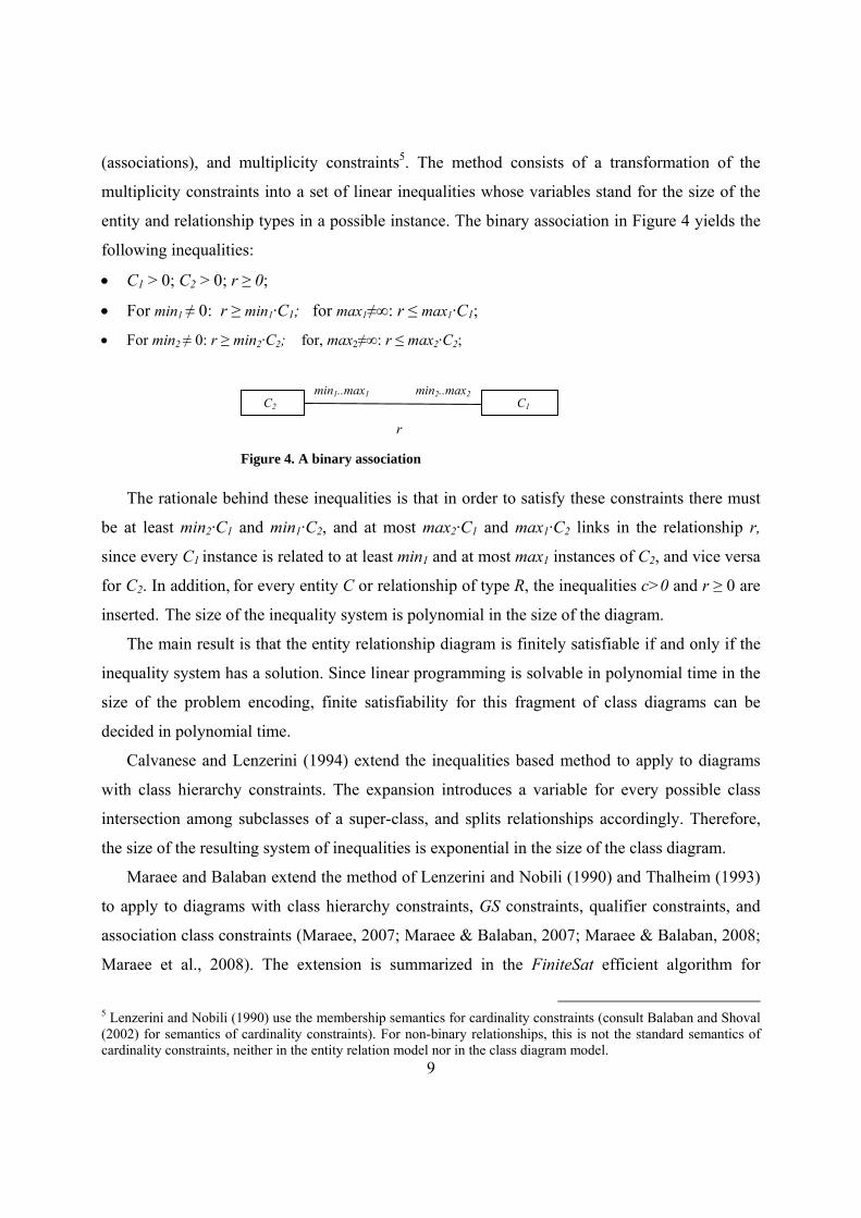
(associations), and multiplicity constraints5. The method consists of a transformation of the
multiplicity constraints into a set of linear inequalities whose variables stand for the size of the
entity and relationship types in a possible instance. The binary association in Figure 4 yields the
following inequalities:
• C1 > 0; C2 > 0; r ≥ 0;
• For min1 ≠ 0: r ≥ min1·C1; for max1≠∞: r ≤ max1·C1;
• For min2 ≠ 0: r ≥ min2·C2; for, max2≠∞: r ≤ max2·C2;
The rationale behind these inequalities is that in order to satisfy these constraints there must
be at least min2·C1 and min1·C2, and at most max2·C1 and max1·C2 links in the relationship r,
since every C1 instance is related to at least min1 and at most max1 instances of C2, and vice versa
for C2. In addition, for every entity C or relationship of type R, the inequalities c>0 and r ≥ 0 are
inserted. The size of the inequality system is polynomial in the size of the diagram.
The main result is that the entity relationship diagram is finitely satisfiable if and only if the
inequality system has a solution. Since linear programming is solvable in polynomial time in the
size of the problem encoding, finite satisfiability for this fragment of class diagrams can be
decided in polynomial time.
Calvanese and Lenzerini (1994) extend the inequalities based method to apply to diagrams
with class hierarchy constraints. The expansion introduces a variable for every possible class
intersection among subclasses of a super-class, and splits relationships accordingly. Therefore,
the size of the resulting system of inequalities is exponential in the size of the class diagram.
Maraee and Balaban extend the method of Lenzerini and Nobili (1990) and Thalheim (1993)
to apply to diagrams with class hierarchy constraints, GS constraints, qualifier constraints, and
association class constraints (Maraee, 2007; Maraee & Balaban, 2007; Maraee & Balaban, 2008;
Maraee et al., 2008). The extension is summarized in the FiniteSat efficient algorithm for
5 Lenzerini and Nobili (1990) use the membership semantics for cardinality constraints (consult Balaban and Shoval (2002) for semantics of cardinality constraints). For non-binary relationships, this is not the standard semantics of cardinality constraints, neither in the entity relation model nor in the class diagram model.
min1..max1 min2..max2 C1 C2
r
Figure 4. A binary association

10
deciding finite satisfiability in UML class diagrams. The scope of the algorithm is defined by the
structure of the class hierarchy in a knowledge base, rather than by a fragment of the language.
Example: The application of FiniteSat to the class diagram in Figure 5 yields the inequality
system below. We use the variables ds for DNASegment, gn for Gene, ch for Chromosome, gm
for Genome and ds-gn for the DNASegment-Genome association.
• Multiplicity constraints: ds-gn ≥ 1·ds, ds-gn ≤ 1·ds, ds-gn ≥ 1·gn, ds-gn ≤ 1·gn
• Class hierarchy constraints: ds ≥ gn, ds ≥ ch, ds ≥ gn
• GS constraint: ds > gn+ch+gm
• Non emptiness inequalities: ds, dn, ch, dm, dg > 0, ds-gn≥0
Figure 5. Non-finite satisfiability due to a generalization set constraint
This system has no solution since the multiplicity inequalities imply ds = gn, while the GS
constraint and the non emptiness inequalities require that ds > gn. Therefore, FiniteSat returns
False.
Correctness of the FiniteSat depends on the structure of class hierarchies in the given class
diagram. For that purpose, class hierarchy constraints are viewed as a graph (directed or not),
whose nodes represent classes and its edges represent class hierarchy constraints, directed from
super-classes to their subclasses. Three class hierarchy structures are analyzed: (1) Tree class
hierarchies: A tree structure as in Figure 1; (2) Acyclic class hierarchies: The undirected graph is
acyclic (a tree), as in Figure 6a; (3) Cyclic class hierarchies: The undirected graph is cyclic, as in
Figure 6b, implying unrestricted multiple inheritance.

11
Figure 6. Unconstrained hierarchy structures
The correctness results for FiniteSat are as follows:
1. If the class hierarchy structure in a class diagram CD does not include cycles with a disjoint
or complete GS constraint, then CD is finitely satisfiable if and only if the inequality system
constructed by FiniteSat is solvable.
2. If the class hierarchy structure in a class diagram CD includes cycles with a disjoint or
complete GS constraint, then CD is not finitely satisfiable if the inequality system constructed
by FiniteSat is unsolvable.
Example: [FiniteSat Limitation] The class diagram in Figure 7a is not finitely satisfiable, since
it implies the semantic inter-relations shown in Figure 7b. Yet, FiniteSat yields the solvable
inequality system in Figure 7c. The reason for the failure of FiniteSat lies in the projection of the
disjoint constraint from the A GS to the E GS, which is not recorded in the inequality system.
Recently, FiniteSat was strengthened with propagation of disjoint and complete GS constraints
(Maraee & Balaban, 2009).
Figure 7. A Finite Satisfiability Problem that is not Recognized by the FiniteSat Algorithm
The construction of the inequalities by FiniteSat, and their number is O(n^2), where n is the
number of constraints in the class diagram (Maraee & Balaban, 2009). The size of the inequality
system is O(n) if there are no association class hierarchies.
The Detection Graph Approach A method for detection of the cause for non finite satisfiability is suggested in Hartmann (2001),
Lenzerini & Nobili (1990) and Thalheim (1993). The method is based on construction of a
directed graph, termed the identification graph, whose nodes stand for classes and associations,
and its edges connect association nodes with their end class nodes. The edges are weighted by
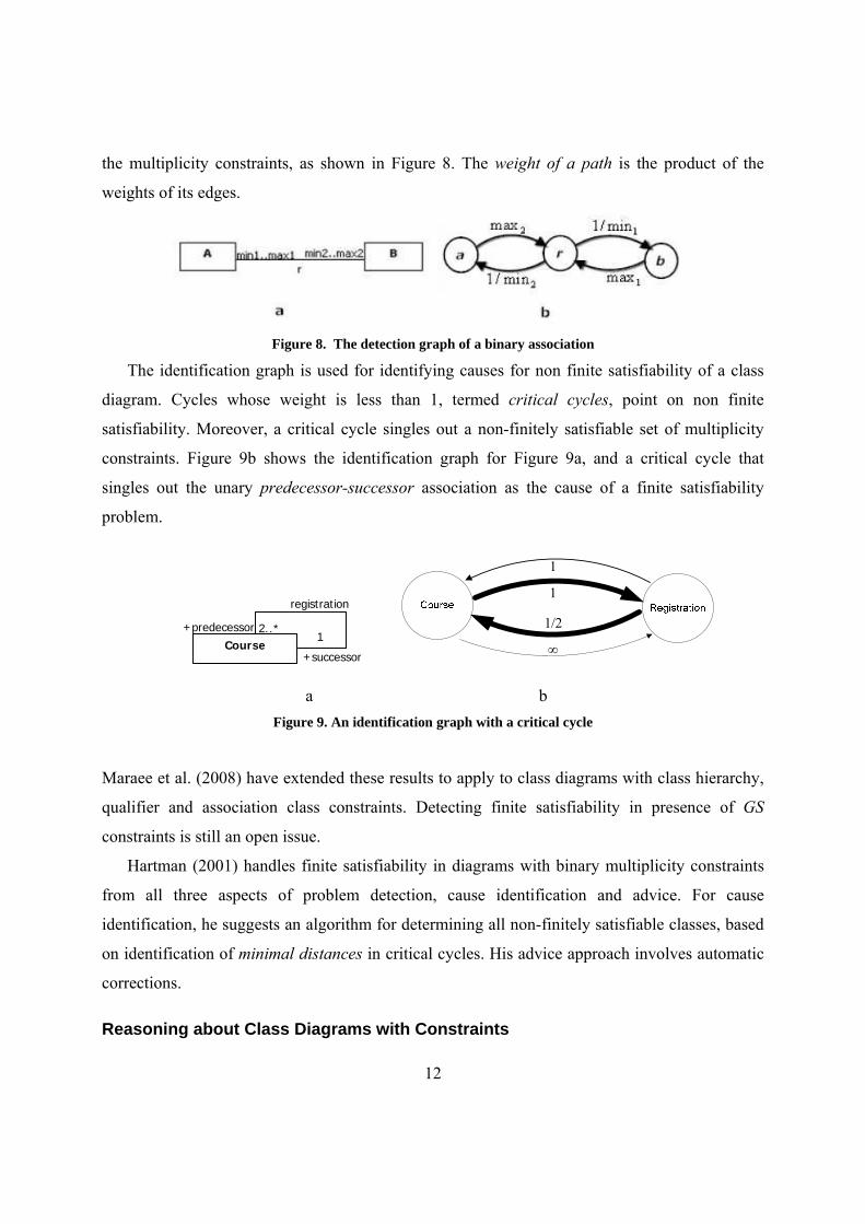
12
the multiplicity constraints, as shown in Figure 8. The weight of a path is the product of the
weights of its edges.
Figure 8. The detection graph of a binary association
The identification graph is used for identifying causes for non finite satisfiability of a class
diagram. Cycles whose weight is less than 1, termed critical cycles, point on non finite
satisfiability. Moreover, a critical cycle singles out a non-finitely satisfiable set of multiplicity
constraints. Figure 9b shows the identification graph for Figure 9a, and a critical cycle that
singles out the unary predecessor-successor association as the cause of a finite satisfiability
problem.
Course
registration
+successor
+predecessor1
2..*
a b
Figure 9. An identification graph with a critical cycle
Maraee et al. (2008) have extended these results to apply to class diagrams with class hierarchy,
qualifier and association class constraints. Detecting finite satisfiability in presence of GS
constraints is still an open issue.
Hartman (2001) handles finite satisfiability in diagrams with binary multiplicity constraints
from all three aspects of problem detection, cause identification and advice. For cause
identification, he suggests an algorithm for determining all non-finitely satisfiable classes, based
on identification of minimal distances in critical cycles. His advice approach involves automatic
corrections.
Reasoning about Class Diagrams with Constraints
1
1
1/2
∞

13
The expressivity of class diagrams is limited to class level interaction and constraints. The
Object Constraint Language OCL (OMG-OCL, 2006; Warmer & Kleppe, 2003) is intended to
extend a UML model (mainly class diagrams) with symbolic constraints. Cabot et al. (2008)
describe a CSP-based tool for reasoning about finite satisfiability of class diagrams that are
extended with OCL constraints. USE is a tool for validation of UML/OCL models (Gogolla et
al., 2001; Richters & Gogolla, 2000). Alloy is a Z based tool for automated analysis of object
structured software specification (Jackson, 2002). Together with the recent UML2Alloy tool
(Anastasakis et al., 2007), it provides a UML/OCL analysis tool. Most UML/OCL tools do not
separate reasoning about visual constraints from symbolic OCL constraints. Therefore, since
OCL, as an unrestricted first order logic language, is undecidable, Cabot et al. (2008) and
Jackson (2002) perform incomplete bounded verification.
EXPLAINING AND REPAIRING CORRECTNESS PROBLEMS USING A PATTERN-
BASED APPROACH
The goal of a model development tool is to help the designer in developing a correct and high
quality model. For this purpose, the tool should point to design problems, explain their cause and
suggest possible repairs. The detection and cause identification methods, surveyed in the
previous section, do not function as advice and explanatory tools. Consider, for example, the non
finite satisfiability problem in Figure 1. The identification graph method (Maraee et al., 2008)
detects the critical cycle CatalyzedReaction, Enzyme, Protein, Molecule, Chemical, Reaction,
CatalyzedReaction. But the critical status of this cycle may be caused by several interactions of
constraints:
1. The Enzyme-Chemical class hierarchy and the multiplicity constraints in the rest of the
critical cycle.
2. The Reaction-CatalyzedReaction class hierarchy and the multiplicity constraints in the
rest of the critical cycle.
3. The multiplicity constraints in the critical cycle.

14
The reason lies in the second interaction: The intended direction of class hierarchy, from the
subclass CatalyzedReaction to the super-class Reaction is reversed. This final conclusion is
domain dependent, and can be made by the designer, based on personal knowledge, or by
consulting appropriate domain ontologies. Therefore, a desirable approach seems to involve
proposing possible explanations, and letting the designer take the final repair decision (in
contrary to the approach of Hartman (2001)).
We suggest bridging the gap between current correctness handling methods and desirable
explanations and advice by using a pattern based approach. This idea is influenced from the
design patterns (Gamma et al, 1994) paradigm. Design patterns function as advices for solving
typical problems that can occur in various contexts. They fulfill an educational role: awareness to
design patterns yields better solutions. By way of analogy, patterns of correctness problems
characterize typical situations in which correctness problems arise, analyze the causes, and
suggest possible solutions. Their educational role is to increase the awareness of designers to
avoid contradictory constraints that cause correctness problems.
The patterns based approach proposed in this paper reminds the anti-patterns (Brown et al,
1998) and the refactoring (Fowler, 1999) techniques for software improvement. Anti-patterns
present bad solutions to typical problems (that possibly cause more problems than they solve),
followed by suggestions of desirable solutions. In that sense, anti-patterns are an extension of
design patterns. The patterns presented in this paper can be viewed as anti-patterns that point to
negative designs, and suggest various repairs.
Refactoring is a change of the internal structure of software that preserves its functional
behavior. Refactorings are usually applied to already running, correct code. Modern IDEs
(Integrated Development Environments) like Eclipse and IntelliJ IDEA offer some automated
refactorings at the code level. Recently, there is also research at the direction of model level
refactoring (Mens and Tourwe, 2004, Mens et al., 2007). France et al. (2003) propose an
approach for refactoring automation, where a metamodel is used for writing refactorings as
pattern transformations (Kim, 2008). The approach proposed in this paper, also consists of
patterns and transformations aimed at model improvement. The major difference is that
correctness handling patterns aim at repairing problems, and might change the meaning of
models.

15
We present incorrectness patterns, which characterize typical cases of erroneous design.
Each pattern describes a correctness problem, caused by problematic interaction of constraints,
and can be identified by characteristic structures within a class diagram. A pattern is also
associated with advices for repairing the identified problem. Each pattern includes proofs that
justify the identification structure and the repair advices.
We distinguish four correctness problem types – inconsistency, non-finite satisfiability,
redundancy, and incomplete design – which represent two aspects of correctness. The first two
are problems of formal correctness, while the last two are problems of design quality, which is
another form of correctness: A low quality design is formally correct, but does not meet some
criteria for desirable design. Such criteria include for example duplication and missing
specifications. In this paper two patterns are described in detail, and few others are presented in a
condensed format, including only concrete examples.
Patterns of Inconsistency and Non-Finite Satisfiability Problems
Inconsistency is caused by contradictory constraints that cannot be simultaneously satisfied.
Finite satisfiability problems are caused by cycles of conflicting multiplicity constraints. The
cycles might involve other constraints, like class hierarchies, generalization sets, association
classes, inter-association and OCL constraints.
Lack of Finite Satisfiability patterns:
1. Multiplicity constraint interaction:
Pattern Name: Pure Multiplicity Cycle (PMC)
Pattern Description: A cycle of associations with multiplicity constraints might introduce a
finite satisfiability problem.
Pattern Identification Structure:
A minimal association cycle in which all multiplicity constraints are different from (0, *). Figure
10 shows the pattern’s identification structure.
Figure 10. The PMC Pattern
C1 C2
Cn
a12 +r'1+r1
m'n1..m'x1mn1..mx1Cn-1
an-1n
+r'n-1
+rn-1
m'n-1..m'xn-1
mn-1..mxn-1
an1+rn
+r'm
mn..mxn
m'n..m'xn
1. All classes are different. 2. All multiplicity constraints are different from (0,*).

16
The identification structure can be symbolically described as follows:
In this expression, [ ] represents an association between Ci and Ci+1, with the designated
multiplicities. The symbolic representation can be formally described using regular expression
notation, where “*” denotes unbounded repetition, “*n..m” denotes bounded repetition, “+”
denotes alternatives, and “,” denotes sequencing (concatenation):
Concrete Examples:
Example 1: Figure 11 presents a class diagram with a minimal association cycle that does not
include a (0,*) multiplicity constraint, and causes a finite satisfiability problem. To see that, note
that each course has a single successor and at least two predecessors. Therefore, if the number of
courses in a legal instance is C, and the number of predecessor-successor links is D, then D must
satisfy: D = C*1 and D ≥ C*2, implying the inequality: C ≥ C*2, that can be satisfied only by an
empty or an infinite extension of the class Course.
Course
registration
+successor
+predecessor1
2..*
Example 2: A class diagram with a non-minimal association cycle that includes a (0,*)
constraint, and has a finite satisfiability problem:
In Figure 12 the finite satisfiability problem is caused by the minimal cycle created by the s and t
associations.
Figure 11. Non-finite satisfiability due to a multiplicity constraint interaction
A Bq 0..*0..*r
0..11..*
Cs 11
t1 3
Figure 12. A non-minimal association cycle that includes a (0,*) constraint

17
A Bq+0..1 2..*
r
0..11..*
Example 3: A class diagram with an association cycle that includes a multiplicity constraint (0,
n) for n ≠ *, and a constraint (m, *), for m ≠ 0, and causes a finite satisfiability problem. Figure
13 present an example of a class diagram with such a cycle.
Pattern justification:
The above examples justify the following requirements in the pattern identification structure:
1. Example 1 shows that a minimal association cycle without a (0,*) multiplicity constraint
can cause a finite satisfiability problem. Example 3 shows that a finite satisfiability
problem can occur even when the cycle includes (0, n) for n ≠ *, or (m, *), for m ≠ 0,
multiplicity constraints.
2. Example 2 shows that dropping the minimality requirement might overlook some
problems.
We still need to justify the "no (0, *) multiplicity constraint” requirement. That is, we have to
show that a minimal association cycle with a (0,*) multiplicity constraint cannot cause a finite
satisfiability problem. The proof relies on properties of the identification graph of the cycle (see
Figure 9, Lenzerini & Nobili (1990), and Maraee et al. (2008)), and on the two propositions
below. It shows that if a minimal association cycle (AC) includes a (0,*) multiplicity constraint,
then its identification graph IGAC does not include a critical cycle.
Proposition 1: Let AC be a minimal association cycle, and IGAC be its identification graph. Then
a cycle in IGAC that includes an edge for a 0 minimum constraint or a * maximum constraint is
not critical.
Proof: The weight of such edges in IGAC is ∞.
Proposition 2: Let AC = be a
minimal association cycle, such that its identification graph IGAC includes a critical cycle. Let
IGcycle be a minimal critical cycle in IGAC , i.e., a critical cycle that cannot be pruned. Then, the
Figure 13. Non-finite satisfiability due to a multiplicity constraint interaction

18
edges of IGcycle correspond to alternating minimum-maximum constraints in AC: max'1, min1,
max'2, min2, …, minn, or maxn, min'n, maxn-1, min'n-1, …, min'1. Proof: A cycle in IGAC results either from traversing an association path in AC forwards and
backwards, or from traversing an association cycle in AC in a single direction. But, IGcycle cannot
include successive edges for a multiplicity constraint (mini, maxi), since such edges create a cycle
whose weight is greater than 1, and therefore can be pruned, in contradiction to the minimality of
IGcycle. Therefore, IGcycle results from traversing an association cycle in AC in a single direction.
Since AC is minimal (does not include inner cycles), IGcycle traverses through all associations in
AC, implying its claimed structure.
The following two claims provide the justification for the pattern identification structure:
Claim 1: A minimal association cycle AC that includes a (0,*) constraint cannot create a finite
satisfiability problem.
Proof: Proposition 2 implies that every minimal cycle in IGAC, that traverses through all
associations of AC, includes an edge, either for the 0 or for the * constraints, and therefore
cannot be critical.
Pattern verification: The pattern identification structure is not tight. That is, it characterizes a
necessary but not sufficient condition on the multiplicity constraints in an association cycle. In
order to find out whether a PMC causes a finite satisfiability problem, there is a need to further
check the conditions introduced in Claim 2.
Claim 2: A minimal association cycle AC (as in Proposition 2) without (0,*) creates a finite
satisfiability problem if and only if one of the following conditions holds:
max'1, · max'2 , ·… max'n ≤ min1 · min2 ·… minn maxn, · maxn‐1 , ·… max1 ≤ min'n · min'n‐1 ·… min'1
Proof: By Proposition 2, the edges of a minimal critical cycle in IGAC correspond to alternating
minimum-maximum constraints in AC: max'1, min1, max'2, min2, …, minn, or maxn, min'n,
maxn-1, min'n-1, …, min'1. The conditions in the claim capture the conditions that the cycle is
critical.
Repair advice: Consider increasing a maximum constraint or decreasing a minimum constraint,
such that one of the conditions in Claim 2 holds. For example, in Figure 11, the minimum
predecessor requirement for a course can be decreased, or alternatively the maximum successor

19
Course
registration
+successor
+predecessor1..2
1..*
requirement can be increased as shown in Figure 14. The repair solves the finite satisfiability
problem since the new inequalities for D and C (see the explanation to Figure 11 in page 16) are
D ≥ C*1 and D ≤ C*2, which are solvable.
2. Interaction of multiplicity and class hierarchy constraints:
Pattern Name: Multiplicity Hierarchy Cycle (MHC).
Pattern Description: A cycle of associations with multiplicity constraints and class hierarchy
constraints might introduce a finite satisfiability problem
Pattern Identification Structure:
A minimal cycle of associations and class hierarchy constraints, in which all multiplicity
constraints are different from (0,*) and all class hierarchy constraints are in the same direction.
Figure 15 shows the pattern’s identification structure.
Figure 15. The MHC Pattern
1. All classes are different. 2. All multiplicity constraints are different from (0,*).
Figure 14. A repaired class diagram of Figure 11
C1
Cl
C2mn1,mx1mn'1,mx'1
Cg
Ch
Cj Ckmn'j,mx'jmnj,mxj
Cn

20
Academic
FacultyMember Graduate
+advisor
+student
1
2
Reaction Chemical
CatalyzedReaction
Enzyme
Protein DNA
substrate
1..* 1
catalyzed2
1
The pattern describes possibly interleaved chains of association and class hierarchy constraints
(in the same direction). The pattern can be precisely described by the regular expression notation,
which supports alternation and sequencing. First, we introduce an expression that captures the
class hierarchy constraint: C D stands for C is a subclass of D. The expression
denotes either an association or a class hierarchy
constraint. The expression { denotes a sequence of
up to n alternating association or class hierarchy constraints. The overall pattern is captured by
the expression:
{ Concrete Examples: Figure 16a presents a multiplicity constraint cycle that involves class Graduate, which is a
subclass of class Academic, and whose instances must be related to Academic instances.
Therefore, assuming that G and A are the number of graduates and academics, respectively, the
number of student-advisor links in every legal instance must be both, G*1 and A*2, implying G
= A*2. In addition, the extensions of Graduate and Academic must satisfy G ≤ A, since Graduate
is a subclass Academic. These constraints can be satisfied only by empty or infinite extensions.
Figure 16b presents a finite satisfiability problem which is a reduced version of the finite
satisfiability problem in Figure 1.
Figure 16. Non-finite satisfiability due to multiplicity and class hierarchy constraints
a b

21
Pattern justification:
The above examples show that an association–class-hierarchy cycle can cause a finite
satisfiability problem. It is left to show that the minimality of the cycle and the “no (0,*)
multiplicity constraint” are necessary conditions. As in the previous pattern, the proof relies on
the identification graph of the cycle (Maraee et al., 2008). The identification graph is constructed
in two steps:
1. First, every class hierarchy constraint in the cycle is replaced by an association with
multiplicity constraints (0, 1) and (1, 1) on the sub-class and super-class sides,
respectively. The intuition is that every object of the sub-class is also an object of the
super-class, but not necessarily vice-versa. Maraee & Balaban (2007) have shown that
this transformation preserves the consistency and finite-satisfiability properties.
2. This replacement creates a plain association cycle, for which the identification graph can
be constructed, following Lenzerini & Nobili (1990). For this cycle, the PMC pattern
already justifies the “no (0,*) multiplicity constraint” requirement.
Since the class hierarchy to association translation does not insert a (0,*) multiplicity constraint,
we conclude that if the original association cycle is minimal and does not include a (0,*)
multiplicity constraint, the cycle might cause a finite satisfiability problem, whilst the presence
of a (0,*) multiplicity constraint guarantees that no finite satisfiability problem can be caused by
the cycle.
Pattern verification:
In order to find out whether an MHC may cause a finite satisfiability problem, there is a need to
check the conditions in Claim 2 described above. Repair advice:
Consider relaxation of the multiplicity constraints, as in the PMC repair advice. A different
advice might be to switch the direction of a class hierarchy constraint in the cycle. The latter
repairs the finite satisfiability as shown in the following proposition.
Proposition 3: A minimal cycle of association with multiplicity constraints and class hierarchy
constraints in opposite direction, cannot introduce a finite satisfiability problem.
22
Reaction Chemical
CatalyzedReaction
Enzyme
Protein DNA
substrate
1..* 1
catalyzed2
1
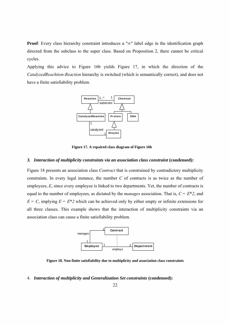
Proof: Every class hierarchy constraint introduces a "∞" label edge in the identification graph
directed from the subclass to the super class. Based on Proposition 2, there cannot be critical
cycles.
Applying this advice to Figure 16b yields Figure 17, in which the direction of the
CatalyzedReachtion-Reaction hierarchy is switched (which is semantically correct), and does not
have a finite satisfiability problem.
3. Interaction of multiplicity constraints via an association class constraint (condensed):
Figure 18 presents an association class Contract that is constrained by contradictory multiplicity
constraints. In every legal instance, the number C of contracts is as twice as the number of
employees, E, since every employee is linked to two departments. Yet, the number of contracts is
equal to the number of employees, as dictated by the manages association. That is, C = E*2, and
E = C, implying E = E*2 which can be achieved only by either empty or infinite extensions for
all three classes. This example shows that the interaction of multiplicity constraints via an
association class can cause a finite satisfiability problem.
Employee Departmentemploys
21
Contractmanages
1
1
Figure 18. Non-finite satisfiability due to multiplicity and association class constraints
4. Interaction of multiplicity and Generalization Set constraints (condensed):
Figure 17. A repaired class diagram of Figure 16b
23
In Figure 19 the {disjoint, incomplete} constraint suggests that the DNASegment extension
properly includes the Gene, Chromosome and the Genome extensions. Yet, DNASegment
instances are mapped in a 1:1 manner to Genome instances, implying that the sets have the same
size. The only solution for proper set inclusion with equal size is that the sets are either empty or
infinite.
Figure 19. Non-finite satisfiability due to multiplicity and generalization set constraints
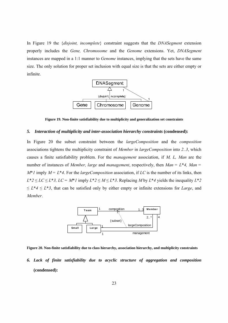
5. Interaction of multiplicity and inter-association hierarchy constraints (condensed):
In Figure 20 the subset constraint between the largeComposition and the composition
associations tightens the multiplicity constraint of Member in largeComposition into 2..3, which
causes a finite satisfiability problem. For the management association, if M, L, Man are the
number of instances of Member, large and management, respectively, then Man = L*4, Man =
M*1 imply M = L*4. For the largeComposition association, if LC is the number of its links, then
L*2 ≤ LC ≤ L*3, LC = M*1 imply L*2 ≤ M ≤ L*3. Replacing M by L*4 yields the inequality L*2
≤ L*4 ≤ L*3, that can be satisfied only by either empty or infinite extensions for Large, and
Member.
MemberT eam
LargeSmall
composition 1..31
largeComposition1
2..*
management1
4{subset}
Figure 20. Non-finite satisfiability due to class hierarchy, association hierarchy, and multiplicity constraints
6. Lack of finite satisfiability due to acyclic structure of aggregation and composition
(condensed):

24
The asymmetric property of aggregation/composition requires that a part of an assembly cannot
aggregate one of its aggregators. Consequently, a legal instance of a class diagram cannot
include aggregation cycles. Figure 21 describes a class whose instances aggregate instances of
the same class.
The whole-part association defines a one-to-one function from the set Origin to itself, which
maps an element of Origin to its single part. If the extension of Origin is a finite non-empty set,
the mapping must be cyclic. Therefore, Origin can have only empty or infinite extensions.
Origin
1
Wahler et al. (2009) present the No-Cyclic-Dependency pattern (NCD pattern), which prevents
cyclic links between objects of classes within a path of associations6. The authors show that in
order to satisfy this constraint, it is sufficient that two association ends in opposite direction in
the association cycle have a zero minimal multiplicity as shown in Figure 22. A repair advice for
this pattern can be based on Wahler's NCD pattern.
Inconsistency patterns (condensed):
1. Contradictory disjoint generalization set constraints:
6 Constraint patterns are parameterized pattern expressions that can be instantiated to form a specific constraint (Ackermann & Turowski, 2006; Wahler 2008).
Figure 21. Unsatisfiability due to the asymmetry of aggregation
Figure 22. An aassociation cycle that satifies Wahler’s NCD pattern

25
Figure 23 presents the diamond class hierarchy, in which the disjoint constraint enforces the
MacroMolecule class to be empty.
Figure 23. Inconsistency due to a generalization-set constraint: disjoint
2. Contradictory disjoint and complete generalization set constraints:
In Figure 24 the interaction of the disjoint and the complete constraints forces class B to be
empty, since an instance of E must be an instance of C or D, which are disjoint from B.
A
B C D
E
{disjoint}
{complete}
Figure 24. Inconsistency due to generalization-set constraints: disjoint and complete
3. Interaction of redefinition and disjoint constraints:
In Figure 25, a common instance e of classes E and F must be r- related to an instance x of class
A. But, since e is an object of F and b1 redefines r1, x must be an instance of B. However, e is
also an instance of E, and since c1 redefines r1, x is also an instance of the C, which violates the
disjoint constraint (Costal & Gómez, 2006). Therefore, the interaction of the disjoint and the
Chemical
Molecule Compound Element
MacroMolecule
{disjoint}

26
redefinition constraints implies that classes F and E must be disjoint. Consequently, in every
legal instance, class G must be empty.
Patterns of Redundant and Incomplete Design (condensed)
Redundancy means that the specification can be simplified without affecting its meaning. For
example, classes or associations that have the same extension in all instances are redundant.
Values that cannot be realized in multiplicity constraints are redundant. In the first case, one of
the equivalent elements can be removed. In the latter case, the multiplicity value range can be
tightened.
Incomplete design means that implied constraints do not appear in the diagram. It reflects
a lack of awareness on the designer’s part, and therefore shows low design quality. In some
cases, incomplete design can prevent the detection of correctness problems, and consequently be
rejected by modeling tools. Some problems of class diagram redundancy and implicit
consequences are identified and discussed by Berardi et al. (2005) and Costal & Gomez (2006).
1. Redundancy due to equivalent classes:
Class redundancy occurs mainly due to class hierarchy. In Figure 26 the class D extension is a
subset of A extension due to the class hierarchy constraint, and the sets have the same size, since
B
A
E F
D
C
{disjoint}
r+r1+r21..**
+b1 {redefine r1}+f1 {redefine r2}11
+c1 {redefine r1}+e1 {redefine r2}
11
G
Figure 25. Inconsistency due to redefinition and disjoint constraints

27
A instances are mapped in a 1:1 manner to D instances. If the sets are finite, they must be equal,
and therefore the D class is redundant and can be removed.
2. Redundancy due to equivalent associations This case is similar to the previous pattern. Association equivalence occurs due to hierarchy of
association classes. In Figure 27, R and Q are associations that constrain the association classes,
P and S, respectively, and are also constrained by a 1:1 multiplicity constraint. Therefore, P and
S have equal extensions in all legal instances, and associations R and Q, and one of the
association classes P and S are redundant.
Figure 27. Redundancy due to equivalent associations
3. Redundancy of multiplicity constraint values:
In Figure 28, the multiplicity constraint 1..* of the Member class in the LargeComposition
association is too loose. The subset constraint between the LargeComposition and the
Composition associations, and the 1..3 multiplicity constraint of Member in Composition, imply
that the maximum multiplicity constraint of Member in LargeComposition can be 3.
Figure 26. Redundancy due to equivalent classes
A
B C D+b
+a
1
1A
B C
+b
+a1
1
A BR
nm
P

28
C4
C2 C3
C1 r
+r2+r10..*0..*
+q2 {subsets r2}+q111
MemberT eam
LargeSmall
Composition 1..31
LargeComposition1
1..*{subset}
MemberT eam
LargeSmall
Composition 1..31
LargeComposition1
1..3{subset}
Figure 28. Redundancy due to cardinality constraints
4. Incomplete deign:
Figure 29 shows an incomplete design: The semantics of the subsets constraint on association
ends requires that it appears on both ends of an association. A modeling tool might add derived
constraints so to provide a more precise model.
Figure 29. Design improvement due to incomplete hierarchy structure class equivalence
SUMMARY In this paper we have analyzed correctness problems in UML class diagrams, surveyed existing
approaches for handling correctness of UML class diagrams, and proposed a pattern-based
approach for identifying correctness problems and for providing explanations and repair advices.
The proposed approach aims to bridge the gap between current correctness handling methods
and desirable explanations and advice. Our work is motivated by the belief that correctness
management is essential for supporting advanced IDE and CASE tools in all application areas of
UML class diagrams. In addition, the emerging model driven development approach requires
reliable models that are equipped with powerful reasoning capabilities for assuring high quality
models.
We intend to develop an on-line catalog of incorrectness patterns. The catalog will
accumulate knowledge regarding design problems. The intention is to use the patterns for
C4
C2 C3
C1r +r2+r1
0..*0..*
+q2 {subsets r2}+q1 {subsets r1}
0..*0..*
29
detecting design problems, as well as for educational purposes. We intend to further develop the
pattern-based approach presented here, examine its computational complexity and programmatic
applicability and combine it within an implementation of existing cause identification methods.
We envision that the next generation of modeling tools will apply some correctness
management facilities. Tools will employ a mixture of reasoning methods, applying simple
scalable methods in an incremental way, and resorting to heavy translation-based reasoning
when other methods fail. Our ultimate goal is to develop a model level IDE that combines the
patterns catalog within its modeling support.
REFERENCES Ackermann, J., & Turowski, K. (2006). A Library of OCL Specification Patterns to Simplify Behavioral Specification of Software Components. In Proceedings of the 18th International Conference on Advanced Information Systems Engineering, CAiSE 2006, Luxembourg (pp. 255-269). Springer, Germany.
Ali, A. B., Boufares, F. & Abdellatif, A. (2006). On the global coherence of integrity constraints in UML class diagrams. In Proceeding of the 24th IASTED international conference on Database and applications, Anaheim, CA (pp. 109-114). ACTA Press,.
Anastasakis, K., Bordbar, B., Georg, & G., Ray, I. (2007). UML2Alloy: A Challenging Model Transformation. In Proceedings of the 10th International Conference Model Driven Engineering Languages and Systems, MoDELS 2007, Nashville, USA (pp. 436-450). Springer, Germany.
Artale A., Calvanese D., Kontchakov R., Ryzhikov V., & Zakharyaschev M. (2007). Complexity of Reasoning over Entity-Relationship Models. In Proceedings of the 20th International Workshop on Description Logic, DL 2007, Brixen-Bressanone, Italy (pp. 163-170). CEUR-WS, Germany.
Balaban, M. & Maraee, A. (2006). Consistency of UML Class Diagrams with Hierarchy Constraints. In Proceedings of the 6th International Conference on Next Generation Information Technologies and Systems, NGITS 2006, Kibbuts Shefayim, Israel (pp. 71-82). Springer, Germany.
Balaban, M. & Shoval, P. (2002). MEER -- An EER Model Enhanced with Structure Methods. Information Systems, 27, 245-275.
Berardi, D., Calvanese, D., & De Giacomo, G. (2005). Reasoning on UML class diagrams. Artificial Intelligence, 168 (1), 70-118.
Blaha, M., Premerlani, W., & Shen, H. (1994). Converting OO Models Into RDBMS Schema. IEEE Software, 11 (3), 28-39.
Boufares, F. & Bennaceur, H. (2004). Consistency Problems in ER-schemas for Database Systems. Information Sciences, 163 (4), 263-274.
30
Brown, W. J., Malveau, R. C., McCormick, H. W., & Mowbray, T. J. (1998), AntiPatterns: Refactoring Software, Architectures, and Projects in Crisis. John Wiley & Sons. Cabot, J. and Clariso, R. & Riera, D. (2008). Verification of UML OCL Class Diagrams using Constraint Programming. In Proceedings of the 2008 IEEE International Conference on Software Testing Verification and Validation Workshop, ICSTW'08, Lillehammer, Norway (73-80). IEEE Computer Society, Washington, DC, USA.
Cadoli, M., Calvanese, D., De Giacomo, G. & Mancini, T. (2004). Finite satisfiability of UML class diagrams by constraint programming. In Proceedings of the CP-04 Workshop on CSP Techniques with Immediate Application, Toronto, Canada.
Calvanese, D., & Lenzerini, M. (1994). On the Interaction between ISA and Cardinality Constraints. In Proceedings of the 10th IEEE International Conference on Data Engineering, Houston, Texas, USA (pp. 204-213). IEEE Computer Society, Washington, DC, USA.
Calvanese, D., De Giacomo, G., Lenzerini, M., Nardi, D., & Rosati, R. (1998). Description Logic Framework for Information Integration. In Proceedings of International Conference on Principles of Knowledge Representation and Reasoning, KR'98, Trento, Italy (pp. 2-13). Morgan Kaufman, Los Altos, CA.
Carsten L., Ulrike S., & Lidia T. (2005). The Complexity of Finite Model Reasoning in Description Logics. Information and Computation, 199, 132-171.
Costal, D., & Gomez, C., (2006). On the Use of Association Redefinition in UML Class Diagrams, Conceptual Modeling. In Proceedings of the 25th International Conference on Conceptual Modeling, ER 2006, Tucson, Arizona, USA (pp. 513-527). Springer, Germany.
Cranefield, S. & Purvis, M. (1999). UML as an ontology modeling language. In Proceedings of the Workshop on Intelligent Information Integration, Stockholm, Sweden (pp. 46-53). CEUR-WS, Germany.
Cranefield, S. (2001). Networked knowledge representation and exchange using UML and RDF. Journal of Digital Information, 1(8).
Dobing, B. & Parsons, J. (2006). How UML is used. Communication of the ACM, 49 (5), 109-113.
Eclipse, http://eclipse-plugins.info/, 2006.
Falkovych, K., Sabou, M., & Stuckenschmidt H. (2003). UML for the Semantic Web: Transformation-Based Approaches. In Knowledge Transformation for the Semantic Web, (92-106). IOS Press; illustrated edition.
Fowler, M. (1999) Refactoring: Improving design of existing code. Addison-Wesley.
France, R., Chosh, S., Song, E., & Kim, D.K. (2003). A metamodeling approach to pattern-based model refactoring, IEEE Software, 20 (5), 52-58.
Gamma, E., Helm, R., Johnson, R., & Vlissides, J. M. (1994) Design Patterns: Elements of Reusable Object-Oriented Software, Addison-Wesley.
31
Gasevic, D., Djuric, D., Devedzic, V., & Damjanovi, V. (2004). Converting UML to OWL ontologies. In Proceedings of the 13th international World Wide Web Conference, New York, USA (pp. 488-489). ACM Press, USA.
Gogolla, M., Bohling, J. & Richters, M. (2001). Validating UML and OCL models in USE by automatic snapshot generation. Journal on Software and System Modeling, 4(4), 386 398.
Haarslev, V., & Möller R. (2001). RACER System Description, In Proceedings of the International Joint Conference on Automated Reasoning, IJCAR'2001, Siena, Italy (pp. 701–705). Springer, Germany.
Hartmann, S. (2001). Coping with Inconsistent Constraint Specifications. In Proceedings of the 20th International Conference on Conceptual Modeling, ER 2001, Yokohama, Japan (pp. 241-255). Springer, Germany.
Heckel, R. & Voigt H. (2003). Towards consistency of web service architectures. In Proceedings of the 7th World Multiconference on Systemics, Cybernetics, and Informatics, Orlando, Florida, USA.
Horrocks, I. (1998). The FaCT system. In Proceedings of the 2nd International Conference on Analytic Tableaux and Related Methods, TABLEAUX'98, Oisterwijk, The Netherlands (pp. 307-312). Springer, Germany
Huzar, Z., Kuzniarz, L., Reggio, G., & Sourrouille, J-L. (2004). Consistency Problems in UML-Based Software Development. UML Modeling Languages and Applications, 1-12. Springer, Germany.
Jackson, D. (2002). Alloy: A New Technology for Software Modelling. In Proceedings of the 8th International Conference on Tools and Algorithms for the Construction and Analysis of Systems, Grenoble, France (pp. 20). Springer, Germany.
Jackson, D., & Rinard, M. (2004). Software analysis: a roadmap. In Proceedings of the Conference on the Future of Software Engineering, (pp. 133-145). Springer, Germany.
Kabilan, V., & Johannesson, P. (2004). UML for Ontology Modeling and Interoperability. In Proceedings of the Open InterOp Workshop on Enterprise Modelling and Ontologies for Interoperability, Riga, Latvia, (pp. 349-354). CEUR-WS, Germany.
Karsai, G., Maroti, M., Ledeczi, A., Gray, J., & Sztipanovits J. (2003). Composition and Cloning in Modeling and Meta-Modeling. IEEE Transactions on Control System Technology, 12 (2), 263- 278.
Kim, D. (2008). Software Quality Improvement via Pattern-Based Model Refactoring. In Proceedings of the 2008 11th IEEE High Assurance Systems Engineering Symposium, Nanjing, China, (pp. 293-302). IEEE Computer Society, Washington, DC, USA.
Kogut, P. A., Cranefield, S., Hart, L., Dutra, M., Baclawski, K., Kokar, M. M., & Smith, J. E. (2002). UML for Ontology Development, The Knowledge Engineering Review, 17 (1), 61 – 64.

32
Kozlenkov, A., & Zisman, A. (2004). Discovering, Recording, and Handling Inconsistencies in Software Specifications. International Journal of Computer and Information Science, 5(2), 89-108.
Lange, C.F.J., Chaudron, M.R.V., & Muskens J. (2006). In Practice: UML Software Architecture and Design Description. IEEE Software, 23 (2), 40-46.
Lenzerini, M. & Nobili, P. (1990). On the satisfiability of dependency constraints in entity-relationship schemata, Information Systems, 15 (4), 453-461.
Maraee A., & Balaban, M. (2006). Efficient Decision of Consistency in UML Diagrams with Constrained Generalization Sets. In Proceedings of the first Workshop on Quality in Modeling, Genova, Italy ().
Maraee, A. (2007). Finite Satisfiabilty Problems in UML Class Diagram. Unpublished Master thesis, Ben-Gurion University of the Negev.
Maraee, A., & Balaban, M. (2007) Efficient Reasoning About Finite Satisfiability of UML Class Diagrams with Constrained Generalization Sets. In Proceedings of the 3rd European Conference Model Driven Architecture - Foundations and Applications, Haifa, Israel (pp. 7-31). Springer, Germany.
Maraee, A., & Balaban, M. (2009). Efficient Recognition of Finite Satisfiability in UML Class Diagrams: Strengthening by Propagation of Disjoint Constraints. In the Second International Conference on Model Based Systems Engineering, MBSE'09, Israel.
Maraee, A., Makarenkov, V., & Balaban, M. (2008). Efficient Recognition and Detection of Finite Satisfiability Problems in UML Class Diagrams: Handling Constrained Generalization Sets, Qualifiers and Association Class Constraints. Paper presented at the 1st International Workshop on Model co-evolution and consistency management.
Martin, R.C. (2006). UML for Java™ Programmers. Prentice Hall.
Mens, T. & Tourwe, T. (2004). A survey of software refactoring. IEEE Transaction on. Software Engineering, 30 (2),126-139.
Mens, T., Taentzer, G., & Müller, D. (2007). Challenges in Model Refactoring. In the International workshop on Object-Oriented Reengineering.
OMG-OCL (2006). OCL 2.0 Specification.
OMG-UML (2009). UML 2.2 Superstructure.
Rector, A., Drummond, N., Horridge, M., Rogers, J., Knublauch, H., Stevens, R., Wang, H., & Wroe, C. (2004). OWL Pizzas: Practical Experience of Teaching OWL-DL: Common Errors & Common Patterns. In Proceedings of the European Conference on Knowledge Acquisition, (pp. 63-81). Springer, Germany.
Richters, M. & Gogolla, M. (2000). Validating UML Models and OCL Constraints. In Proceedings of the 3rd International Conference on The Unified Modeling Language, Advancing the Standard, York, UK, (pp. 265-277). Springer, Germany.
33
Rumbaugh, J., Jacobson, I., & Booch, G. (2005). The Unified Modeling Language Reference Manual, Second Edition, Addison-Wessly, 2005.
Satoh, K., Kaneiwa, K., & Uno, T. (2006). Contradiction Finding and Minimal Recovery for UML Class Diagrams. In Proceedings of the 21st IEEE/ACM International Conference on Automated Software Engineering, Tokyo, Japan (pp. 277-280). IEEE Computer Society, Washington, DC, USA.
Schild, K. (1992). From Terminological Logics to Modal Logics. Description Logics, 101-104.
Stahl, T., Voelter, M., & Czarnecki, K. (2006). Model-Driven Software Development: Technology, Engineering, Management, Wiley.
Sunye, G., Pollet, D., Le Taraon, Y., & Jezkel J.-M. (2001). Refactoring UML models. In Proceedings of the 4th International Conference on The Unified Modeling Language, Modeling Languages, Concepts, and Tools, UML 2001, Toronto, Canada (pp. 134-148). Springer, Germany.
Thalheim, B. (1993). Fundamentals of Entity-Relationship Modeling. Annals Mathematics and Artificial Intelligence, 7, 197-256,
Timm, J.T.E. & Gannod, G., (2005). A model-driven approach for specifying semantic web services. In Proceeding of International Conference of Web Services, Orlando, Florida, USA (pp. 313–320). IEEE Computer Society, Washington, DC, USA.
Tsarkov, D., & Horrocks, I. (2006). FaCT++ description logic reasoner: System description. In Proceedings of the 3rd International Joint Conference on Automated Reasoning, Seattle, WA, USA (pp. 292-297).
Unhelkar, B. (2005). Verification and Validation for Quality of UML 2.0 Models, Addison Wesley. Wahler, M. (2008). Using Patterns to Develop Consistent Design Constraints. PhD thesis, ETH Zurich, Switzerland, No. 17643, 2008.
Wahler, M., Basin, D., Brucker, A. D., & Koehler, J. (2009). Efficient Analysis of Pattern-Based Constraint Specifications, Software and Systems Modeling.
Warmer, J. & Kleppe, A. (2003). The Object Constraint Language: Getting Your Models Ready for MDA, Addison-Wesley.