Embed Size (px)
Citation preview
Protection System with FACTS Device Controllers to
Increase Power Transfer Capability
Achyar Maulana Pratama1, Erdi Nindito Rumono
2, Ginas Alvianingsih
3
1NPM: 1206201422,
2NPM: 1206201523,
3NPM: 1206201580
Departement of Electrical Engineering, Faculty of Engineering, University of Indonesia
Abstract—The aim of the paper is to study power flow control
through transmission lines and the protection system with
FACTS device. FACTS or flexible alternating current
transmission system is a system composed of static equipment
used for the AC transmission of electrical energy. It is meant to
enhance controllability and increase power transfer capability of
the network. It is generally a power electronics-based system.
Index Terms—digital relay; Flexible AC transmission systems
(FACTS) device controllers; power electronics; power flow control;
transient stability; transmission line.
I. INTRODUCTION
Flexibility of electric power transmission is the ability to
accommodate changes in the electric transmission system or
operating conditions while maintaining sufficient steady state
and transient margins. Then, flexible AC transmission system
is an alternating current transmission systems incorporating
power electronic-based and other static controllers to enhance
controllability and increase power transfer capability.
FACTS Controller is a power electronic-based system and
other static equipment that provide control of one or more AC
transmission system parameters [1]. FACTS device can be
used to control power flow, limit short-circuit currents,
mitigate subsynchronous resonance, damp out power
oscillations, and enhance transient stability [2]. In this paper,
FACTS device that will be discused are thyristor controlled
series capasitor (TCSC), thyristor switched series capasitor
(TSSC), distributed power flow controller (DPFC), and
voltage source converter.
There are several types of FACTS controllers. Example of
series connected controllers are Thyristor Controlled Series
Capasitor (TCSC) and Thyristor Switched Series Capasitor
(TSSC). Thyristor Controlled Series Capasitor (TCSC) is a
capasitive reactance compensator which consist of a series
capasitor bank shunted by thyristor controlled reactor in order
to provide a smoothly variable series capasitive reactance.
Thyristor Switched Series Capasitor (TSSC) is a capasitive
reactance compensator which consist of a series capasitor
bank shunted by a thyristor switched reactor to provide a step-
wise control of series capasitive reactance. [1]
One of the combined shunt and series connected
controllers in FACTS is Distributed Power Flow Controller
(DPFC). DPFC emerges from the UPFC (Unified Power Flow
Controller), where UPFC is a combination of a static
synchronous compensator (STATCOM) and a static
synchronous series compensator (S3C) which are coupled via
a common dc link, to allow bi-directional flow of real power
between the series output terminals of the S3C and the shunt
output terminals of the STATCOM, and are controlled to
provide concurrent real and reactive series line compensation
without an external electric energy source. [1]
The employment of series/shunt compensation of
transmission lines by above devices creates certain problems
for their protective relays and fault locators using conventional
techniques because of the rapid changes introduced by the
associated control actions in primary system parameters, such
as line impedances and load currents. There are some
multiline voltage-source (VSC)-based FACTS controllers are
introduced to control the power flows of multilines
simultaneously. [5]
II. DIRECTIONAL RELAYING IN THE PRESENCE OF A
THYRISTOR-CONTROLLED SERIES CAPASITOR
This section addresses the problems with directional
relaying in the presence of TCSC in a line and proposes a
solution. It is found that a single classifier using the phase
information of sequence components is inadequate to provide
direction of fault for all situations for a line with TCSC. More
reliable protection algorithms can be achieved by combining
several protection principles together.
A. TCSC’s four modes of operation
TCSC operates with four modes of operations depending
on the situation:
1. Blocking mode
2. Bypass mode
3. Capasitive boost mode
4. Inductive boost mode
B. Voltage and Current Inversion Condition
Voltage inversion at a relay bus occurs when the total
impedance between the voltage source and the fault is
inductive and simultaneously the impedance between the bus
and the fault point is capacitive. Voltage inversion results in
the relay seeing the forward fault in reverse direction.
For a fault at F and with TCSC in capacitive mode, the
fault current through the relay will be

(1)
Fig 1. Reactance diagram of the line with TCSC
Current lags or leads the voltage by 90 , depending on the
sign of the denominator. Further
(2)
Vm will be inverted when the following conditions are
satisfied:
(3)
For above situation, the directional relay will see the fault
in the reverse side.
For a forward fault in the line, if the current at the relay
location leads the relay voltage by 90 due to the large
capacitive reactance in the fault loop and simultaneously the
relay voltage is in phase with the source voltage, current
inversion occurs. The condition for current inversion becomes
(4)
At this situation also, the relay will see the fault in the reverse
direction.
C. Classifiers
1) Classifier-1: Phase Angle Between the Positive-
Sequence Component of Fault Current and Voltage: The angle
between the positive-sequence fault current and voltage (Φ1)
is a common technique for directional relaying. With
during a fault in the system, the rule of
decision with such a classifier in the normal line will be: a
positive angle corresponds to a fault in the upstream and
negative angle for the downstream fault. During capacitive
mode of operation, for the fault in the Fx side, Φ1x is positive
and provides the correct direction of fault. For a fault in the Fy
side, Φ1y is again positive, resulting in an incorrect direction
of fault due to the voltage inversion. During voltage inversion,
the angle between fault and prefault voltage at the relay
location is much higher as shown in Fig. 2(b) and is used as
the indicator of voltage inversion. During current inversion,
the fault voltage at the relay location is more than the prefault
voltage. The change in magnitude of positive-sequence fault
and prefault voltage and Φ1 are positive and are used as the
indicator of current inversion. For an inductive mode of
operation, for a fault in the Fx side, the positions of phasors
are the same as shown in Fig. 2(a). For fault in the Fy side
during the inductive mode of TCSC, the phasor positions are
shown in Fig. 2(c). Φ’1y in this situation is negative and
provides a correct direction of fault.
Fig. 2. Phasor diagrams for classifier-1. (a) For a fault in
the Fx side. (b) For a fault in the Fy side for capasitive mode
operation (voltage inversion). (c) For a fault in the Fy side for
inductive mode of operation.
2) Classifier-2: Phase Angle Between Positive-Sequence
Superimposed Voltage and Current: The second classifier
determines the direction of fault by considering the angle (Φ2)
between the superimposed relay voltage and current. The
superimposed components are obtained as
(5) (6)
And Φ2 = ∟∆VM - ∟∆IM, where VMF and Vmpre are the fault
and prefault voltages at the relay point, respectively, and IMF
and Impre are the fault and prefault currents at the relay point,
respectively. The decision rule with such a classifier will be: if
the angle difference is positive, then the fault is in the
upstream (Fx side) and if it is negative, then the fault is in the
downstream (Fy side). During capacitive mode of operation,
for a fault in the Fx side, the corresponding phasor positions
are shown in Fig. 3(a). The superimposed component IM lags
the superimposed component VM, providing proper fault
direction (the angle difference Φ2x being positive).
For a fault in the Fy side, the superimposed component IM
leads the superimposed component VM, providing proper fault
direction (the angle difference Φ2y being negative) as shown

in Fig. 3(b). For faults in the Fx and Fy sides during inductive
mode of operation, the phasor diagrams are the same
as for the capacitive mode of operation. The superimposed
component approach has limitations during the load change in
the system.
Fig. 3. Phasor diagrams for classifier-2 for the capasitive
and inductive mode of operation. (a) In the Fx side. (b) In the
Fy side.
3) Classifier-3: Phase Angle Between the Positive-
Sequence Component of Fault Current and Prefault Current:
The third classifier obtains the direction of fault by using the
angle between the fault current and prefault current. For a fault
in the Fx side, the corresponding phasor diagram is provided
in Fig. 4(a). The angle Φ3x between Impre and INF is positive
and the decision for fault direction would be correct. For the
fault in the Fy side during current inversion as shown in Fig.
4(b), the relay fault current ILF leads Ipre, which contradicts the
without inversion condition. This will result in an incorrect
decision by the classifier. During current inversion, the fault
voltage at the relay location is more than the prefault voltage
as shown in Fig. 4(b). At this situation, if Φ3 and ∆V are
positive, then current inversion is assumed.
With the classifier being current based, for voltage
inversion, this classifier will not be affected. For inductive
mode of operation, for a fault in the Fx side, the phasor
diagram is the same as shown in Fig. 4(a). For the Fy side
fault, the corresponding phasor diagram is shown in Fig. 4(c).
In this case, the classifier correctly identifies the fault
direction.
Fig. 4. Phasor diagrams for classifier-3. (a) For a fault in
the Fx side. (b) For a fault in the Fy side for capasitive mode
operation. (c) For a fault in the Fy side for inductive mode of
operation.
D. Voting Method
In case of a line with TCSC, the variation in line reactance
changes the power flow in the line. Due to the variation in
reactance, the fault path may become capacitive or inductive.
It is observed that the voltage and current inversions may
occur at certain situations. From the study, it is found that a
single classifier does not perform correctly for all of the fault
situations. Further, all three classifiers do not fail for a
particular case simultaneously. A voting method is proposed
to combine all three decisions of the classifiers to derive the
final fault direction. In the voting method, the final decision is
based on the maximum votes marked against a particular
decision. The majority voting technique is easy to implement
and is applied to the decision process that produces a unique
class label as output and requires no training.
In a voting technique, suppose are the outputs of each
classifier with C elements, where C is the number of output
decisions. The output of each classifier can be ―1‖ or ― 1‖ for a
two-class problem like directional relaying and in that case.
At time , the decision rule selects the output as the class
that carries the majority vote
(7)
X is derived from di, which is a vector of the same length as
the number of classifiers (N). The matrix D can be formulated
from the data of having different C classes. If the decision of
the classifier belongs to a class, it is assigned ―1‖ or else ―0‖
in the D matrix. y(j) is a vector of length C and each element
indicates the total number of votes for a particular class. The
least square technique using one-cycle data is used to estimate
the phasors. The three classifiers estimate the fault direction
and the majority voting technique provides the direction of
fault at a situation. [2]
III. AN ADAPTIVE CONTROLLER FOR POWER SYSTEM STABILITY
IMPROVEMENT AND POWER FLOW CONTROL BY MEANS OF A
THYRISTOR SWITCHED SERIES CAPASITOR (TSSC)
Thyristor switched series capacitor (TSSC) is a device
capable of changing the apparent reactance of a line in a
number of discrete steps. The controller is developed using a
continuous approach, making it suitable for use also with
devices like the thyristor controlled series capacitor (TCSC)
having continuous reactance control. The proposed controller
is a power-oscillation-damping (POD) controller, which
includes features for transient stability improvement and
power flow control. POD is traditionally performed by power
system stabilizers (PSS) connected to the automatic voltage
regulators (AVR) of the generators in the power system.
Properly tuned, these can effectively damp both local and
inter-area modes of power oscillation. Most approaches are
based on a power system model with full or reduced
complexity, which is linearized. In such a system, linear
control theory can be applied and the poles of the closed-loop
system can be placed such that the damping of the critical
oscillation modes is improved.
The nature of interarea oscillations is often such that there
is a dominant mode of oscillation, which is significantly less
damped than all other modes. With this in mind, a simple way
to reduce the total power grid is to view it as a system split
into two grid areas and the reactances of the lines
interconnecting the areas, as seen in Fig. 1. Here, each area is
represented by a single synchronous machine with a lumped
moment of inertia.
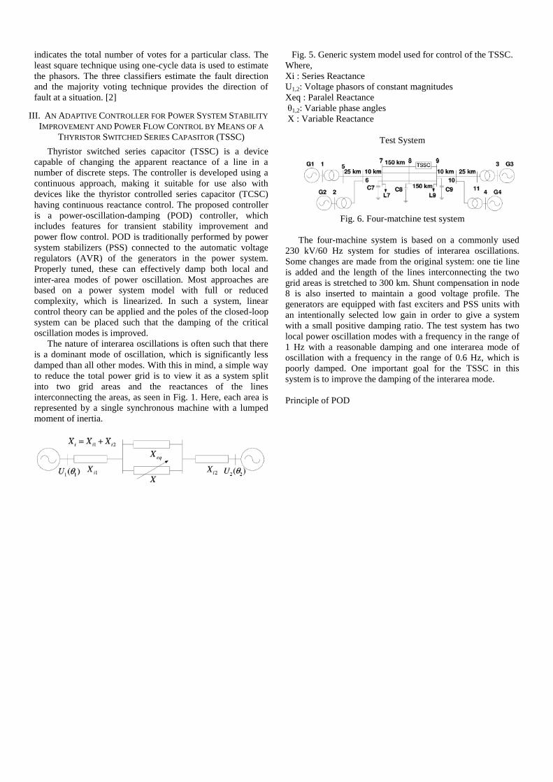
Fig. 5. Generic system model used for control of the TSSC.
Where,
Xi : Series Reactance
U1,2: Voltage phasors of constant magnitudes
Xeq : Paralel Reactance
θ1,2: Variable phase angles
X : Variable Reactance
Test System
Fig. 6. Four-matchine test system
The four-machine system is based on a commonly used
230 kV/60 Hz system for studies of interarea oscillations.
Some changes are made from the original system: one tie line
is added and the length of the lines interconnecting the two
grid areas is stretched to 300 km. Shunt compensation in node
8 is also inserted to maintain a good voltage profile. The
generators are equipped with fast exciters and PSS units with
an intentionally selected low gain in order to give a system
with a small positive damping ratio. The test system has two
local power oscillation modes with a frequency in the range of
1 Hz with a reasonable damping and one interarea mode of
oscillation with a frequency in the range of 0.6 Hz, which is
poorly damped. One important goal for the TSSC in this
system is to improve the damping of the interarea mode.
Principle of POD

If a three-phase to ground fault at node 8 is simulated at t =
1.0 s and cleared after 100 ms with no line disconnection and
no action of the CSC, a poorly damped inter area oscillation is
established, as shown in Fig. 7.Fig. 8 shows that this is indeed
possible. If the controller is limited to act only at times
coinciding with the high and low peaks of the oscillation, it is
theoretically possible to cancel out the oscillation at any given
peak. However, Fig. 8 also shows that a very large change in
the level of compensation is necessary to fulfill the
requirement resulting in a very high level of the power
transmitted on the CSC line. In order to find a practical use of
this principle, it is necessary to extend it to a two-step practice.
Fig. 9 shows this procedure. Here, the controller acts twice on
consecutive peaks in the power oscillation, which results in an
almost total cancellation of the inter area oscillation. With this
technique, it is possible to control the final power on the line
with the CSC since the first step in the sequence can be chosen
with an optional magnitude, whereas the second step can
always cancel the oscillation according to the single-step
argument mentioned earlier. Now, what remains is to find a
way to determine the necessary step magnitudes of the CSC
action to fulfill the requirements. This problem is solved
assuming that the grid can be accurately modeled by the
generic system model in Fig. 5. [4]
IV. DISTRIBUTED POWER FLOW CONTROLLER (DPFC)
The DPFC employs the distributed FACTS (D-FACTS)
concept, which is to use multiple small-size single-phase
converters instead of the one large-size three-phase series
converter in the UPFC. As the D-FACTS converters are
single-phase and floating with respect to the ground, there is
no high-voltage isolation required between the phases.
Fig. 10 Fig. 9
Fig. 8 Fig. 7

The UPFC is the combination of a static synchronous
compensator (STATCOM) and a static synchronous series
compensator (SSSC), which are coupled via a common dc
link, to allow bidirectional flow of active power between the
series output terminals of the SSSC and the shunt output
terminals of the STATCOM. The components of the UPFC
handle the voltages and currents with high rating; therefore,
the total cost of the system is high. Due to the common dc-link
interconnection, a failure that happens at one converter will
influence the whole system. To achieve the required reliability
for power systems, bypass circuits and redundant backups
(backup transformer, etc.) are needed, which on other hand,
increase the cost.
Fig 11. Simplified representation of a UPFC
The DPFC is able to control all system parameters: the line
impedance, the transmission angle, and bus voltage. The
DPFC eliminates the common dc link between the shunt and
series converters. The active power exchange between the
shunt and the series converter is through the transmission line
at the third-harmonic frequency. Comparing with the UPFC,
the DPFC have two major advantages: 1) low cost because of
the low-voltage isolation and the low component rating of the
series converter and 2) high reliability because of the
redundancy of the series converters.
Fig 12. Flowchart from UPFC to DPFC
Fig 13. DPFC configuration
A. DPFC Principle
Two approaches are applied to the UPFC to increase the
reliability and to reduce the cost; they are as follows. First,
eliminating the common dc link of the UPFC and second
distributing the series converter, as shown in Fig. 12. By
combining these two approaches, the new FACTS device—
DPFC is achieved.
The DPFC consists of one shunt and several series-
connected converters. The shunt converter is similar as a
STATCOM, while the series converter employs the D-FACTS
concept, which is to use multiple single-phase converters
instead of one large rated converter. Each converter within the
DPFC is independent and has its own dc capacitor to provide
the required dc voltage. The configuration of the DPFC is
shown in Fig. 13. The DPFC also requires a high-pass filter
that is shunt connected at the other side of the transmission
line, and two Y–Δ transformers at each side of the line.
1. Eliminate DC Link
(8)
Equation above describes that the active power at different
frequencies is isolated from each other and the voltage or
current in one frequency has no influence on the active power
at other frequencies. The independency of the active power at
different frequencies gives the possibility that a converter
without power source can generate active power at one
frequency and absorb this power from other frequencies.
Fig 14. Active power exchange between DPFC converters
By applying this method to the DPFC, the shunt converter
can absorb active power from the grid at the fundamental
frequency and inject the current back into the grid at a
harmonic frequency. According to the amount of required
active power at the fundamental frequency, the DPFC series
converters generate a voltage at the harmonic frequency,
thereby absorbing the active power from harmonic
components.
The high-pass filter within the DPFC blocks the fundament
frequency components and allows the harmonic components
to pass, thereby providing a return path for the harmonic
components. The shunt and series converters, the high-pass
filter, and the ground form the closed loop for the harmonic
current.
Fig 15. Utilize grounded Y-∆ transformer to provide the path
for the zero-sequence third harmonic
Due to the unique characters of third-harmonic frequency
components, the third harmonic is selected to exchange the
active power in the DPFC. In a three-phase system, the third
harmonic in each phase is identical, which is referred to as
―zero-sequence.‖ The zero-sequence harmonic can be
naturally blocked by Y–Δ transformers, which are widely used
in power system to change voltage level. Therefore, there is no
extra filter required to prevent the harmonic leakage to the rest
of the network. In addition, by using the third harmonic, the
costly high-pass filter, as shown in Fig. 14, can be replaced by
a cable that is connected between the neutral point of the Y–Δ
transformer on the right side in Fig. 13 and the ground.
Because the Δ winding appears open circuit to the third-
harmonic current, all harmonic current will flow through the
Y-winding and concentrate to the grounding cable, as shown
in Fig. 15. Therefore, the large-size high-pass filter is
eliminated.
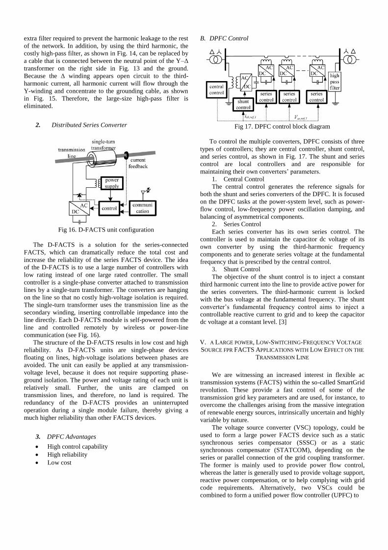
2. Distributed Series Converter
Fig 16. D-FACTS unit configuration
The D-FACTS is a solution for the series-connected
FACTS, which can dramatically reduce the total cost and
increase the reliability of the series FACTS device. The idea
of the D-FACTS is to use a large number of controllers with
low rating instead of one large rated controller. The small
controller is a single-phase converter attached to transmission
lines by a single-turn transformer. The converters are hanging
on the line so that no costly high-voltage isolation is required.
The single-turn transformer uses the transmission line as the
secondary winding, inserting controllable impedance into the
line directly. Each D-FACTS module is self-powered from the
line and controlled remotely by wireless or power-line
communication (see Fig. 16).
The structure of the D-FACTS results in low cost and high
reliability. As D-FACTS units are single-phase devices
floating on lines, high-voltage isolations between phases are
avoided. The unit can easily be applied at any transmission-
voltage level, because it does not require supporting phase-
ground isolation. The power and voltage rating of each unit is
relatively small. Further, the units are clamped on
transmission lines, and therefore, no land is required. The
redundancy of the D-FACTS provides an uninterrupted
operation during a single module failure, thereby giving a
much higher reliability than other FACTS devices.
3. DPFC Advantages
High control capability
High reliability
Low cost
B. DPFC Control
Fig 17. DPFC control block diagram
To control the multiple converters, DPFC consists of three
types of controllers; they are central controller, shunt control,
and series control, as shown in Fig. 17. The shunt and series
control are local controllers and are responsible for
maintaining their own converters’ parameters.
1. Central Control
The central control generates the reference signals for
both the shunt and series converters of the DPFC. It is focused
on the DPFC tasks at the power-system level, such as power-
flow control, low-frequency power oscillation damping, and
balancing of asymmetrical components.
2. Series Control
Each series converter has its own series control. The
controller is used to maintain the capacitor dc voltage of its
own converter by using the third-harmonic frequency
components and to generate series voltage at the fundamental
frequency that is prescribed by the central control.
3. Shunt Control
The objective of the shunt control is to inject a constant
third harmonic current into the line to provide active power for
the series converters. The third-harmonic current is locked
with the bus voltage at the fundamental frequency. The shunt
converter’s fundamental frequency control aims to inject a
controllable reactive current to grid and to keep the capacitor
dc voltage at a constant level. [3]
V. A LARGE POWER, LOW-SWITCHING-FREQUENCY VOLTAGE
SOURCE FPR FACTS APPLICATIONS WITH LOW EFFECT ON THE
TRANSMISSION LINE
We are witnessing an increased interest in flexible ac
transmission systems (FACTS) within the so-called SmartGrid
revolution. These provide a fast control of some of the
transmission grid key parameters and are used, for instance, to
overcome the challenges arising from the massive integration
of renewable energy sources, intrinsically uncertain and highly
variable by nature.
The voltage source converter (VSC) topology, could be
used to form a large power FACTS device such as a static
synchronous series compensator (SSSC) or as a static
synchronous compensator (STATCOM), depending on the
series or parallel connection of the grid coupling transformer.
The former is mainly used to provide power flow control,
whereas the latter is generally used to provide voltage support,
reactive power compensation, or to help complying with grid
code requirements. Alternatively, two VSCs could be
combined to form a unified power flow controller (UPFC) to

provide both series and shunt reactive compensation. In doing
so, both the active and reactive power flow can be controlled.
In addition, the proposed converter could be used as a part of
any large power electronic system where the topology fits the
application requirements.
A. Description of the Converter
1. Parallel Combination of Two Inverter Poles
Fig 18. Parallel connection of two inverter poles using an IPT
The IPT (Inter Phase Transformers) is effectively a single
primary, single secondary transformer, where the two
windings are connected in series. The series connection point
is taken as the output and the remaining terminals are the two
inputs. The two windings, closely coupled, are arranged so
that the flux created by equal currents entering the input
terminals is canceled out, that is, their amp-turns are equal and
of a different sign, leaving in the core the flux created by the
voltage difference between the two input terminals.
2. Series Transformers Connection
Due to the inherent amp-turns balance created in each of
the transformer limbs, as Ampere’s law explains, the currents
iA5 and iA6 have the same shape, but are 30o
out of phase,
leading or lagging depending on the transformer connection.
Moreover, as explained shortly, provided that the converter
outputs are phase-shifted by 30o
to match the phase shift of the
transformer, the overall output voltage will be double to that
of each inverter. That is, the inverters can be considered as
two series-connected voltage sources, which, by virtue of the
galvanic isolation provided by the transformer, are allowed to
share a common and better optimized dc bus.
B. Modulation Strategies
There are 2 ways to made modulation for converter
connection to reduce harmonic. The first one with full-wave
48-pulse modulation and the second one with Selective
Harmonic Elimination of Three Angles (SHE-3).
1. Full-Wave 48-Pulse Modulation
In this strategy, each of the inverter poles produces a
voltage wave form with the lowest possible switching
frequency allowed for in a 3-L NPC inverter. This, which
has an average frequency of 100 Hz over a complete cycle,
consists in applying 0V, only during a short angle of θ,
centered on each of the zero crossings.
The harmonic content of that waveform, expressed in
Fourier coefficients, can be easily calculated as
(9)
This waveform has no even harmonics present.
Moreover, some of the harmonics can be greatly attenuated
by the right choice of the θ angle. For instance, if θ is made
equal to 15o, the 11th 13th, 35th, and 37th harmonics will
be attenuated by a value of 0.1305, whereas the
fundamental component will be merely reduced by a factor
of 0.9915.
2. SHE of Three Angles (SHE-3)
This implementation consists in generating an SHE wave
form where the three switching angles per quarter-cycle
α1, α2, and α3, are chosen such that the harmonics
eliminated at the inverter pole output vA1G is the 11th and
13th, while controlling the waveform amplitude.
Subsequently, the 23rd and 25th
harmonics are mitigated at
the IPT by choosing the γ angle equal to 7.5o. Repeat the
time control for switch to eliminate the others harmonic
distorsion orde until the output waveform like a normal
wave form.
VI. IMPACT OF VSC-BASED MULTILINE FACTS CONTROLLERS
ON DISTANCE PROTECTION OF TRANSMISSION LINES
The employment of series/shunt compensation of
transmission lines by above devices creates certain problems
for their protective relays and fault locators using conventional
techniques because of the rapid changes introduced by the
associated control actions in primary system parameters, such
as line impedances and load currents. There are some multiline
voltage-source (VSC)-based FACTS controllers, such as an
Interline Power-Flow Controller (IPFC), Generalized Interline
Power-Flow Controller (GIPFC), and Generalized Unified
Power-Flow Controller (GUPFC) are introduced to control the
power flows of multilines simultaneously. Multiline VSC
based FACTS controllers can control different variables of the
power system, such as the bus voltage and independent active
and reactive power flows of two lines by combining three or
more converters working together.
Fig 19. Simplified one-line diagram of multiline FACTS
controllers connected to the middle of the transmission lines
Fig. 19 shows the generic representation of a multiline
VSC based FACTS controller. Different controllers are
achieved by the status of the DC switches, as Table I.

According to this table,when all of the DC switches are
closed, it represents a GUPFC. SSSC1 and SSSC2 in Table I
indicate the static synchronous series compensators (SSSCs)
configured in Line 1 and Line 2, respectively.
A. Multiline VSC-Based FACTS Controllers Impact on
Apparent Impedance
To make FACTS controllers at GUPFC condition, all
switch must be closed so the one line diagram will be
Fig 20. Sample system with GUPFC
In this figure, the GUPFC is connected to the middle of the
line to include the series compensators in the fault loop. VSe1
and VSe2 are the series-injected voltages powered by the
shunt converter, represented by impedance Zsh and current
source Ish. If the converter losses are ignored, then the active
power drawn by the shunt leg is equal to the delivered power
to lines 1 and 2. The performance of relays R1 and R2 for
different fault types, fault locations, and fault resistances Rf is
analyzed to show the impact of different multiline VSC-based
FACTS controllers on distance protection. Faults on Line 1 at
point F between K and H with the per-unit distance x from the
relay location are considered. In this sense, x has a value
between 0.5 and 1.0 for faults between K and H in the sample
system. ZL is theimpedance of each line, and VG is the
voltage measured by R1 and R2 which is the same for both
relays.
B. GUPFC Control System
Although GUPFC has many possible operating modes, it is
anticipated that the shunt converter will generally operate in
automatic voltage-control mode and the series converter will
typically be in automatic power-flow control mode. The
control schemes assume that series and shunt converters
generate output voltage with controllable magnitude and
angle, and that the dc bus voltage will be held substantially
constant.The automatic power-flow control for the series
converter is achieved by means of a vector-control scheme
that regulates the transmission-line current, using a
synchronous reference frame in which the control quantities
appear as dc signals in the steadystate. The appropriate real
and reactive current components are determined for a desired
Prefand Qref, compared with the measured line currents, and
used to derive the magnitude and angleof the series converter
voltage.
C. Simulation result of GUPFC Control System
a. Relay Performance for a Single-Phase Fault (A-G)
Fig 21. Trip characteristics of relay R1 for a single-phase fault
A comparison of the characteristics ABCD with its
counterpart A’B’C’D’ (hatched area without GUPFC)
reveals that GUPFC has an impact on R1 to measure
higher apparent reactance/resistance. This means for a
single-phase fault at Zone I reach of the relay, higher
apparent impedance is seen by the relay, so the fault
falsely appears outside Zone I. In other words, GUPFC
causes the relay to under reach.
b. Relay Performance for a Two-Phase Fault (A-B)
Fig 22. Apparent impedance seen by R1 for a phase-to-phase
fault at 225 km
It can be seen that the trajectories of apparent
impedances do not enter the Zone I mho characteristics for
GUPFC/UPFC, while the trajectory does enter the circle
for IPFC. It can be deduced that GUPFC/UPFC caused the
relay to under reach (i.e., not to detect
the fault at Zone I), while the impact of IPFC is not
remarkable.

c. Relay Performance for a Two-Phase-to-Ground Faults
Fig 23. Apparent impedance seen by different measuring units
of the relay for an ABC fault at 225 km witk GUPFC
The impact of GUPFC for ABG faults is less severe
than the single-phase faults. Despite the fact that the A-B
unit does not cross the trip boundary, it is still less affected
than the single-phase measuring units (A-G and B-G).
d. Impact of Pref and Qref on the Apparent Impedance
Fig 24. Apparent impedance seen by distance relay R1 for
different values of active and reactive power-flow reference
values
As can be seen from this figure, for Pref = Qref = 0,
the power flows are 315.6 MW and ----58.1 MVAr. The
solid line in Fig. 24 shows the variation of the apparent
impedance versus the variation of Pref, while keeping Qref
constant. It can be deduced that Pref has an impact on the
apparent impedance for all of the values between 1.8 p.u.
and 1.2 p.u. with a constant Qref. In the next step, Qref is
varied while Pref is held constant. As Fig. 11 shows, Qref
also affects the apparent impedance such as Pref but to a
lesser extent. The impact of Qref is higher for its lower
values. [5]
VII. CONCLUSIONS
FACTS devices that are developed can be used to
increase the power transfer capability by means of
stabilizing the transient and detect any failures.
Directional relaying in the presence of TCSC is
addressed by three positive-sequence-based classifier
outputs and combined with the voting method to
obtain the direction of fault.
Thyristor switched series capacitor (TSSC) as
controller is developed using a continuous approach.
The proposed controller is a power-oscillation-
damping (POD) controller, which includes features
for transient stability improvement and power flow
control.
The DPFC emerges from the UPFC and inherits the
control capability of the UPFC, which is the
simultaneous adjustment of the line impedance, the
transmission angle, and the bus-voltage magnitude.
The voltage source converter (VSC) is mainly used to
provide power flow control, provide voltage support,
reactive power compensation, or to help complying
with grid code requirements.
Multiline VSC- based FACTS controllers, which are
used to simultaneously control the active and reactive
power flows of multilines, have a remarkable
impacton conventional distance protection of
transmission lines due to the rapid changes
introduced by the associated controlactions in
primary system parameters such as line impedances
and load currents.
Acknowledgment
We gratefully acknowledge to our teachers Mr. Faiz
Husnayain, S.T, M.T, and Mr. Ir. I Made Ardita, M.T, and all
of classmates of power engineering for discussing about the
power electronics in our six semester.
References
[1] R. Adapa, M.H Baker, L. Bohmann K. Clark, K. Habashi, L. Gyugyi, J.
Lemay, A.S. Mehraban, A.K Myers, J. Reeve, F. Sener, D.R Torgerson,
and R.R Wood, ―Proposed Terms and Definitions for Flexible AC Transmission System (FACTS),‖ IEEE Trans. Power Del., vol.12, no.4,
Oct. 1997.
[2] P. Jena and A.K. Pradhan, ―Directional Relaying in the Presence of a
Thyristor-Controlled Series Capasitor,‖ IEEE Trans. Power Del., vol.28,
no.2, Apr. 2013.
[3] Z. Yuan, Sjoerd W. H. De Haan, J.B Ferreira and D. Cvoric, ―A FACTS
Device: Distributed Power-Flow Controller (DPFC),‖ IEEE Trans.
Power Elect., vol.25, no.10, Oct. 2010.
[4] N. Johansson, L. Angquist and H.P Nee, ―An Adaptive Controller for
Power System Stability Improvement and Power Flow Control by Means of a Thyristor Switched Series Capasitor (TSSC),‖ IEEE Trans.
Power Syst., vol.25, no.1, Feb. 2010.
[5] M. Khederzadeh and A. Ghorbani, ―Impact of VSC-Based Multiline FACTS Controllers on Distance Protection of Transmission Lines,‖
IEEE Trans. Power Del., vol.27, no.1, Jan. 2012.
[6] J.C Zabalza, M.A.R Vidal, P.I. Moreno and G. Calvo, ―A Large Power,
Low-Switching-Frequency Voltage Source Converter for FACTS
Applications with Low Effects on the Transmission Line,‖ IEEE Trans. Power Elect., vol.27, no.12, Des. 2012.