Embed Size (px)
Citation preview

MM
Inward Gliding Door System 4
Maintenance Manual
Version 2.0
Release date 2020-10-01
Document ID IG4100001
Project name Inward Gliding Door System 4
Project ID IG4
File name InwardGlidingDoor_MM_IG4_100001.PDF
Template version 20200929R1.73
Inward Gliding Door System 4 Revision history
Maintenance Manual
InwardGlidingDoor_MM_IG4_100001.PDF(2.0) 2020-10-01 page 2 of 22
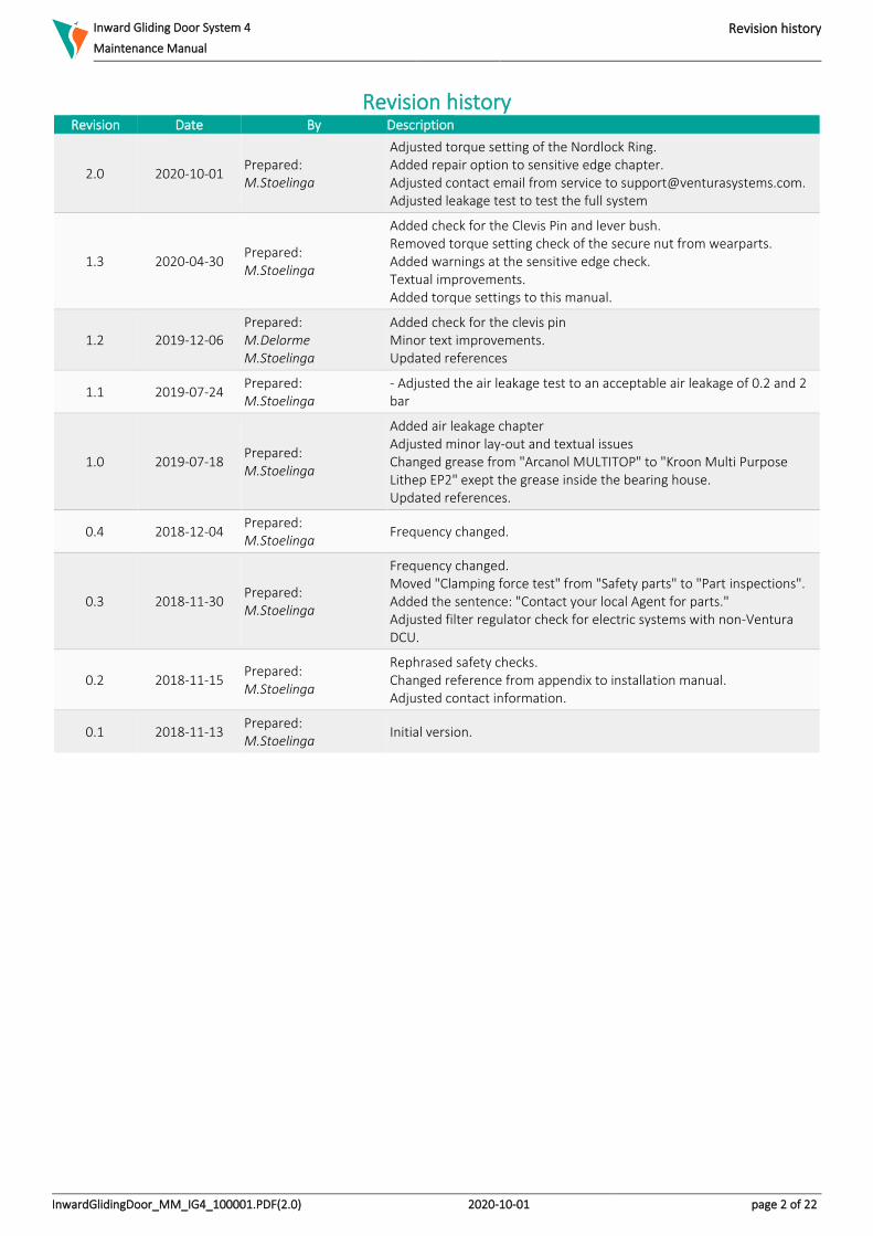
Revision history Revision Date By Description
2.0 2020-10-01 Prepared: M.Stoelinga
Adjusted torque setting of the Nordlock Ring. Added repair option to sensitive edge chapter. Adjusted contact email from service to [email protected]. Adjusted leakage test to test the full system
1.3 2020-04-30 Prepared: M.Stoelinga
Added check for the Clevis Pin and lever bush. Removed torque setting check of the secure nut from wearparts. Added warnings at the sensitive edge check. Textual improvements. Added torque settings to this manual.
1.2 2019-12-06 Prepared: M.Delorme M.Stoelinga
Added check for the clevis pin Minor text improvements. Updated references
1.1 2019-07-24 Prepared: M.Stoelinga
- Adjusted the air leakage test to an acceptable air leakage of 0.2 and 2 bar
1.0 2019-07-18 Prepared: M.Stoelinga
Added air leakage chapter Adjusted minor lay-out and textual issues Changed grease from "Arcanol MULTITOP" to "Kroon Multi Purpose Lithep EP2" exept the grease inside the bearing house. Updated references.
0.4 2018-12-04 Prepared: M.Stoelinga
Frequency changed.
0.3 2018-11-30 Prepared: M.Stoelinga
Frequency changed. Moved "Clamping force test" from "Safety parts" to "Part inspections". Added the sentence: "Contact your local Agent for parts." Adjusted filter regulator check for electric systems with non-Ventura DCU.
0.2 2018-11-15 Prepared: M.Stoelinga
Rephrased safety checks. Changed reference from appendix to installation manual. Adjusted contact information.
0.1 2018-11-13 Prepared: M.Stoelinga
Initial version.

Inward Gliding Door System 4 Preface
Maintenance Manual
InwardGlidingDoor_MM_IG4_100001.PDF(2.0) 2020-10-01 page 3 of 22
Preface The Quality System of Ventura Systems is accredited to EN ISO 9001:2015.
All rights reserved. Disclosure to third parties of this document or any part thereof, or the use of any information contained therein for purposes other than provided for by this document, is not permitted, except with prior and express written
permission from Ventura Systems.

Inward Gliding Door System 4 Table of contents
Maintenance Manual
InwardGlidingDoor_MM_IG4_100001.PDF(2.0) 2020-10-01 page 4 of 22
Table of Contents 1 Introduction ........................................................................................................................................................................................... 6
1.1 Purpose ........................................................................................................................................................................................... 6 1.2 Scope .............................................................................................................................................................................................. 6 1.3 Definitions ...................................................................................................................................................................................... 6 1.4 Acronyms and Abbreviations ......................................................................................................................................................... 6 1.5 References ...................................................................................................................................................................................... 6
1.5.1 External documents ................................................................................................................................................................ 6 1.5.2 Ventura Systems documents .................................................................................................................................................. 6
1.6 Overview ......................................................................................................................................................................................... 6 2 Door installation safety ......................................................................................................................................................................... 7
2.1 General ........................................................................................................................................................................................... 7 2.2 Disclaimer ....................................................................................................................................................................................... 7 2.3 Safety alert symbols ....................................................................................................................................................................... 8 2.4 Safety instructions .......................................................................................................................................................................... 9
3 Maintenance ........................................................................................................................................................................................ 10 3.1 Safety parts ................................................................................................................................................................................... 10
3.1.1 Emergency release ................................................................................................................................................................ 10 3.1.2 Sensitive edge........................................................................................................................................................................ 11
3.2 Wear parts .................................................................................................................................................................................... 12 3.2.1 Clevis pin and lever bush ....................................................................................................................................................... 12 3.2.2 Guide rollers .......................................................................................................................................................................... 13 3.2.3 Bearing bush shaft ................................................................................................................................................................. 13 3.2.4 Bearing bush bottom............................................................................................................................................................. 14 3.2.5 Sliding plate ........................................................................................................................................................................... 14
3.3 Parts inspections .......................................................................................................................................................................... 15 3.3.1 Filter regulator ...................................................................................................................................................................... 15 3.3.2 Clamping force test ............................................................................................................................................................... 16 3.3.3 Air leakage test ...................................................................................................................................................................... 17 3.3.4 grease spiral cable shaft ........................................................................................................................................................ 18
4 Torque Settings.................................................................................................................................................................................... 19 5 Operational checks .............................................................................................................................................................................. 21
5.1 Operation and controls ................................................................................................................................................................ 21 5.2 Safety checks ................................................................................................................................................................................ 21
6 Contact ................................................................................................................................................................................................ 22
List of Figures Figure 1: Spiral cable runs smooth and has no overlength ................................................................................................................... 11 Figure 2: over center position ................................................................................................................................................................ 12 Figure 3: check the clevis pin ................................................................................................................................................................. 12 Figure 4: Guiding shaft ........................................................................................................................................................................... 13 Figure 5: Bottom bearing bush ............................................................................................................................................................... 13 Figure 6: Lever bearing bush .................................................................................................................................................................. 14 Figure 7: Sliding plate ............................................................................................................................................................................. 14 Figure 8: Camozzi filter regulator ........................................................................................................................................................... 15 Figure 9: Camozzi regulator ................................................................................................................................................................... 15 Figure 10: Obstruction test setup .......................................................................................................................................................... 16 Figure 11: Legend for air leakage images .............................................................................................................................................. 17 Figure 12: Testing complete door system .............................................................................................................................................. 17 Figure 13: Spiral cable guiding shaft ...................................................................................................................................................... 18 Figure 14: mark the fasteners with a torque marker. ............................................................................................................................ 19 Figure 15: torque tool VA3860 ............................................................................................................................................................... 19 Figure 16: torque setting overview. ....................................................................................................................................................... 19 Figure 17: World map Ventura locations ............................................................................................................................................... 22
List of Tables

Inward Gliding Door System 4 Table of contents
Maintenance Manual
InwardGlidingDoor_MM_IG4_100001.PDF(2.0) 2020-10-01 page 5 of 22
Table 1: Definitions ................................................................................................................................................................................... 6 Table 2: Acronyms and abbreviations ...................................................................................................................................................... 6 Table 3: External documents .................................................................................................................................................................... 6 Table 4: Ventura Systems documents ...................................................................................................................................................... 6 Table 5: Maintenance frequencies ......................................................................................................................................................... 10 Table 6: General contact information .................................................................................................................................................... 22 Table 7: Parts contact information......................................................................................................................................................... 22

Inward Gliding Door System 4 Introduction
Maintenance Manual Purpose
InwardGlidingDoor_MM_IG4_100001.PDF(2.0) 2020-10-01 page 6 of 22
1 Introduction 1.1 Purpose This maintenance manual describes maintenance and small adjustment procedures for the Ventura inward gliding door system. Together with the installation manual, commissioning manual and system drawings makes a complete set of documentation. It is important to follow all instructions. All instructions must be conducted without air/electric power unless mentioned otherwise. The instructions should be executed for the left and right door leaf when the system contains two door leaves. A well-adjusted door system is less vulnerable to failure. The right maintenance is crucial for the durability of the door system.
1.2 Scope The purpose of this document is to guide trained service mechanics trough the maintenance steps of the inward gliding door system. When repairs have to be made, the mechanic needs to use the repair manual, or the proper service instruction.
1.3 Definitions Definition Description
Wear part Wear is progressive damage to a part caused by relative motion with respect to another substance or part.
Safety part A safety part is a part, which is important to the overall safety of a system.
Table 1: Definitions
1.4 Acronyms and Abbreviations Abbreviation Description
DCU Door Control Unit
HQ Headquarters
IATF International Automotive Task Force
IG Inward Gliding
ISO International Standardization Organization
REG Regulation
PSI Pounds per Square Inch
Table 2: Acronyms and abbreviations
1.5 References 1.5.1 External documents
Reference Description Date
APTA:2013 Standard bus procurement guidelines : A standardized request for proposal contract form for the transit industry
2013-05-01
IATF 16949:2016 Automotive quality management system standard 2016-10-01
ISO 9001:2015 ISO Standard for Quality Management Systems – Requirements. 2015-10-01
REG 107 Rev 08 Uniform provisions concerning the approval of category M2 or M3 vehicles with regard to their general construction (Incorporating all valid text up to: Supplement 1 to 08 series of amendments)
2019-10-15
TS 155 Rev 2 Bus door safety systems 2017-11-23
Table 3: External documents
1.5.2 Ventura Systems documents Reference Type Description Revision Date
IG4100002 IM Inward Gliding Door System 4 : Installation Manual 2.0 2020-05-18 QM000001 DG Documentation Guideline 3.1 2020-01-14
Table 4: Ventura Systems documents
1.6 Overview Section 1 gives an introduction, definitions and overview of this document. Section 2 contains the general door system safety instructions, safety symbols and disclaimer. Section 3 contains the maintenance instructions.

Inward Gliding Door System 4 Door installation safety
Maintenance Manual General
InwardGlidingDoor_MM_IG4_100001.PDF(2.0) 2020-10-01 page 7 of 22
2 Door installation safety 2.1 General Safety of the operator and bystanders is one of the main concerns in designing and developing a new piece of equipment. Ventura's door systems have the proper safety features for common use of the system. An accident can often be avoided by recognizing potentially hazardous situations before an accident occurs. As you install, operate, or maintain the door system, you must be alert to potential hazards. Make sure you have the necessary training, skills and tools to perform any assembly, or maintenance procedures. Improper operation and maintenance of this door system may result in a dangerous situation that may cause injury or death. Ventura Systems cannot anticipate every possible circumstance that may involve a potential hazard. The warnings in this document and on the product are not all-inclusive. If a method of installation or operation is used, which is not specifically recommended by Ventura Systems, you must satisfy yourself that it is safe for you and for others. You should also ensure that the door system will not be damaged or be made unsafe by the installation and/or operational methods you choose. The information, specifications and illustrations in this document are based on the information that was available at the time this document was written and can change at any time without notice.
2.2 Disclaimer The information contained in this maintenance document is based upon reliable technical data at the time the document was published. These instructions are intended for use by persons having the technical knowledge to maintain this door system. The instructions are to be used at the maintenance mechanic’s own discretion and risk. Ventura Systems assumes no responsibility for results obtained or damage incurred from the use of this material either in whole or in part by the installer. This document provides basic instructions for the maintenance of the door system in a step-by-step sequence that will work in most types of maintenances. While effort has been made to ensure the information in this document is correct and complete, we would appreciate it if you would contact us in case of errors.

Inward Gliding Door System 4 Door installation safety
Maintenance Manual Safety alert symbols
InwardGlidingDoor_MM_IG4_100001.PDF(2.0) 2020-10-01 page 8 of 22
2.3 Safety alert symbols This document contains safety messages which alert you to potential personal injury hazards. Obey all safety messages in this document to avoid possible injury or death. The following key words and layouts calls for your attention: DANGER, WARNING, CAUTION and NOTICE. Below are examples of these safety messages. The NOTE message is used for additional information but these are not threatening for the mechanic, bystanders, nor the door system.
DANGER!
Indicates an imminently hazardous situation which, if not avoided, will result in death or serious injury. This signal word is limited to the most extreme situations.
WARNING!
Indicates a potentially hazardous situation which, if not avoided, could result in death or serious injury.
CAUTION!
Indicates a potentially hazardous situation which if not avoided, may result in minor or moderate injury.
NOTICE
Indicates that equipment or property damage can result if instructions are not followed.
NOTE
Additional information important but not threatening for people or to the system.

Inward Gliding Door System 4 Door installation safety
Maintenance Manual Safety instructions
InwardGlidingDoor_MM_IG4_100001.PDF(2.0) 2020-10-01 page 9 of 22
2.4 Safety instructions
WARNING!
This door system is designed for a specific application;
DO NOT modify or use this unit for any application other than for which it was designed.
Door systems operated improperly or by untrained personnel is dangerous. Lack of operation knowledge
may cause high risk.
Do not install this door system if it is damaged. If you are in doubt if the door system has a defect,
immediately stop the installation and contact Ventura Systems.
Do not connect the door system to air or electric supply during the maintenance process. If the manual states otherwise, follow the manual.
Do not attempt to install the door system under influence of drugs or alcohol.
NOTICE
Do not modify the door system or safety devices. Unauthorized modifications may impair its function
and safety.
If equipment has been altered in any way from the original design, Ventura Systems does not accept
any liability for injury or warranty.
If replacement of parts is necessary, genuine factory replacement parts must be used to restore the door
system to its original specifications.
*always disconnect the air and/or electric power while replacing parts. Safety features may not be
active while replacing parts.
Ventura Systems will not accept responsibility for damages as a result of the use of unapproved parts.
While working on the Ventura door systems wear appropriate personal protective equipment.
This list may include but is not limited to: • Protective shoes with slip resistant soles
• Protective goggles, glasses or face shield
• A hard hat
Follow the regional and country laws and safety precautions.

Inward Gliding Door System 4 Maintenance
Maintenance Manual Safety parts
InwardGlidingDoor_MM_IG4_100001.PDF(2.0) 2020-10-01 page 10 of 22
3 Maintenance Maintenance of a door system should only be performed when the bus is positioned on a flat surface to prevent distortion/twisting of the bus body, which can lead to inaccurate measurements of the portal. Whenever the amount of cycles is past, we advise to execute the applicable maintenance. At the table below, we address the chapter names.
Cycles assumption Minimal
maintenance Applicable for
75.000 Every 3 months Safety parts Operational checks
150.000 Every 6 months Wear parts
300.000 Every 12 months Parts inspections
Table 5: Maintenance frequencies
Execute at least the minimal maintenance intervals.
3.1 Safety parts The checks in this chapter are very important. If these parts are not installed correctly, it can have great consequences for the safety of the system. When the system has two door leaves, the checks must be executed for both sides. Ventura Systems recommend to execute all safety checks regularly and at least according to the maintenance intervals mentioned in the table "Maintenance frequencies".
3.1.1 Emergency release Apply power and/or pressure to the system and put the door(s) in closed position.
CAUTION!
Be aware the system could move when applying power and/or pressure to the system.
1. When the system is active, activate the emergency release.
The following events should occur. 2. The power/pressure is released from the system. 3. The door(s) can be opened manually.
• Reset the emergency release.
• Open and close the door(s) using the power source.
WARNING!
Remove the power and/or pressure from the system after executing this step and before you continue.

Inward Gliding Door System 4 Maintenance
Maintenance Manual Safety parts
InwardGlidingDoor_MM_IG4_100001.PDF(2.0) 2020-10-01 page 11 of 22
3.1.2 Sensitive edge Apply power and/or pressure to the system and put the door(s) in closed position.
CAUTION!
Be aware the system could move when applying power and/or pressure to the system.
Do not apply an obstruction with bodyparts. When the safety parts do not function this could result in serious injury.
Put the doors in open position before executing the following steps. Close the doors using the power.
• Press against the right mid seal at a height of 1 meter or less. The doors go to open position.
• Press against the left mid seal at a height of 1 meter or less. The doors go to open position. When the door leaves do not open when pressing the mid seals as described, perform the following checks or execute the repair instruction.
WARNING!
Remove the power and/or pressure from the system before you continue.
• Pull out the cap at the top of the vertical profile. Be aware to not damage the cable, cap or seal.
• Disconnect the sensitive edge from the spiral cable.
• Set the multimeter to continuity mode and connect the multimeter to the connector of the sensitive edge.
Figure 1: Spiral cable runs smooth and has no overlength
1. Be sure there is no force pressing the mid seal which can activate the sensitive edge. Resistance is 8k2Ω or 1k2Ω on the resistor of the sensitive edge.
2. Apply force onto the mid seal of the door leaf. Resistance is approximately 0. ~0 Ω Reconnect the sensitive edge to the spiral cable and perform the following checks.
1. Check if spiral cable moves free on the shaft. 2. Check if all the excess length from the spiral cable is fitted inside the door profile. The spiral cable should be fixed to the
guiding shaft bracket with a tie wrap. Be sure there is a little play. 3. Add multipurpose grease on the spiral cable shaft so the cable moves smoothly.(Use "Kroon Multi Purpose Lithep EP2" or
a grease with similar specifications) When the sensitive edge is not working properly, replace it.
NOTE
The sensitive edge is malfunctioning when the resistance is infinite. ∞ Ω.

Inward Gliding Door System 4 Maintenance
Maintenance Manual Wear parts
InwardGlidingDoor_MM_IG4_100001.PDF(2.0) 2020-10-01 page 12 of 22
3.2 Wear parts These parts wear out and must be replaced when damaged, worn, after the prescribed cycles or after the prescribed time the parts are in usage. When a part has an amount of maximum cycles, it will be mentioned.
3.2.1 Clevis pin and lever bush
• Check if the lever bush is not damaged.
• Check if there are no excessive wear marks on the lever bush.
• Check if there is grease between the clevis pin and the lever bush.
If the bush damaged or worn, replace the bush.
Figure 2: over center position
• Check if the clevis pin is not damaged.
• The Clevis pin has to connect the fork joint to the upper lever of the door shaft.
If the clevis pin is damaged, replace the clevis pin.
Figure 3: check the clevis pin

Inward Gliding Door System 4 Maintenance
Maintenance Manual Wear parts
InwardGlidingDoor_MM_IG4_100001.PDF(2.0) 2020-10-01 page 13 of 22
3.2.2 Guide rollers
Figure 4: Guiding shaft
1. The guide rollers on top of the guiding shafts are not worn or damaged in any way. Check for damage visually and feel if there are no worn places on the guide rollers.
2. The guide rollers do not press against the guide rail while the doors are opening or closing.
3.2.3 Bearing bush shaft • Check if the door shaft is free from vertical play (up and downward movement).
• Check if the door does not squeak. If it does apply some grease between the bearing and bearing bolt. If the door shaft is free from vertical play, continue without executing this step. If there is play, execute the following checks.
Figure 5: Bottom bearing bush
1. Check if the bottom bearing bush is not broken.

Inward Gliding Door System 4 Maintenance
Maintenance Manual Wear parts
InwardGlidingDoor_MM_IG4_100001.PDF(2.0) 2020-10-01 page 14 of 22
3.2.4 Bearing bush bottom
Figure 6: Lever bearing bush
1. Check if the bearing bush on the lever is not broken. 2. Check if the bearing bush on the lever is not blocked by dust and dirt.
3.2.5 Sliding plate The sliding plate at the bottom lever is not heavily worn. when the sliding plate is not worn, continue to the next step.
Figure 7: Sliding plate
1. When the sliding plate is worn, replace the part.

Inward Gliding Door System 4 Maintenance
Maintenance Manual Parts inspections
InwardGlidingDoor_MM_IG4_100001.PDF(2.0) 2020-10-01 page 15 of 22
3.3 Parts inspections These parts can get affected by usage and must be re-adjusted or cleaned when needed. Check the distance settings of the door system in open and closed position following the installation manual. Check the torque settings of the door system following the installation manual.
3.3.1 Filter regulator Check if the system is equipped with a regulator or a filter regulator. If there is no regulator or a filter regulator, skip this step.
1. Check if the pressure of the pneumatic system is 8* bar. *in case of an electric system with a non-Ventura DCU, check if the pressure of the pneumatic system is 6 bar.
2. The Camozzi filter regulator is semi-automatic, meaning the filter will drain itself when the pneumatic pressure drops below 0.3 bar (4.3 PSI) and the drain is open.
3. Replace the filter when it is not clear white.
Figure 8: Camozzi filter regulator
Figure 9: Camozzi regulator
Open drain by turning clockwise Close drain by turning counter clockwise
NOTICE
Depending on the filter regulators location, it is advised to keep the drain closed so it will not spill dirt over vital parts of the bus.

Inward Gliding Door System 4 Maintenance
Maintenance Manual Parts inspections
InwardGlidingDoor_MM_IG4_100001.PDF(2.0) 2020-10-01 page 16 of 22
3.3.2 Clamping force test Be assured all safety features of the system are active. Execute the obstruction test following the applicable regulations for your company. (Regulations Ventura meets are REG107, TS155 or APTA)
Figure 10: Obstruction test setup
1. Setup the measurement system following the user manual included with the measurement tool. 2. Apply power and/or pressure to the system.
CAUTION!
Be aware the system could move when applying power and/or pressure to the system.
3. Put the doors in open position. 4. Execute the test according to the applicable regulations.
When the test is not successful;
• Check the safety parts of system.
• Check adjustments following the installation manual.
WARNING!
Remove the power and/or pressure from the system after executing this step and before you continue.

Inward Gliding Door System 4 Maintenance
Maintenance Manual Parts inspections
InwardGlidingDoor_MM_IG4_100001.PDF(2.0) 2020-10-01 page 17 of 22
3.3.3 Air leakage test All stated air leakage test values are applicable solely on one door system. Only check the leakage on door systems when the door is not functioning properly or air leakage is hearable. Check for damaged air pipes or connectors. Locate the leak by checking air leak noises and feelable airflow coming from the connectors or pipes. To reduce air leakage, maintain the filter regulator at least every 2 months. Manually drain the bowl according to the maintenance manual. Change the filter element inside the bowl, at least every year. Starting pressure of the test is 8 Bars. Test time is one minute. The leakage value is a constant indicator in testing supplied pneumatic parts. The system may leak a maximum of 1 Bar per minute.
To test the air leakage there are three main tests. All of them use a schematic drawing how to connect the Manometer. The icons used are displayed in the legend.
Figure 11: Legend for air leakage images
The testing device can be ordered with number U994. This is a Manometer combined with manual valve. Testing the complete door system
Figure 12: Testing complete door system
1. Connect the testing device between the filter regulator and the rest of the door system as shown in the image above. 2. Start the engine of the bus, air pressure should be 8 Bar. 3. Put the doors in open position. 4. Remove the air pressure at the filter regulator. 5. Set the test device on "open". 6. Turn up the air pressure at the filter regulator till 8 Bar. 7. Turn on the manometer at the testing device by pressing the left button and check the pressure. 8. Set the test device on "testing". 9. Measure the pressure drop for 1 minute in open position, the value from 8 Bar should not drop more than 1 Bar.
Execute the same test but in closed position. 10. Set the test device on "open". 11. Let go of the air pressure at the filter regulator. 12. Remove the testing device and fit the air tubes in their original state. 13. Turn up the air pressure at the filter regulator till 8 Bar. 14. If the value drops more than 1 Bar in one minute, go to the next steps to determine possible cylinder leakage.

Inward Gliding Door System 4 Maintenance
Maintenance Manual Parts inspections
InwardGlidingDoor_MM_IG4_100001.PDF(2.0) 2020-10-01 page 18 of 22
3.3.4 grease spiral cable shaft
Figure 13: Spiral cable guiding shaft
1. The shaft is clean of dirt. 2. There is a layer of grease on the guiding shaft which helps the spiral cable run smoothly over the shaft.
Apply grease when needed. (Use "Kroon Multi Purpose Lithep EP2" or a grease with similar specifications)

Inward Gliding Door System 4 Torque Settings
Maintenance Manual
InwardGlidingDoor_MM_IG4_100001.PDF(2.0) 2020-10-01 page 19 of 22
4 Torque Settings All generic IG settings that require torque tightening are in this chapter. Check all mentioned fasteners on the correct torque settings. In case of a double leaf system, check both sides. The fasteners which connect Ventura parts onto the vehicle are, in most cases, non-Ventura parts. Therefor the torque of these fasteners is not defined by Ventura.
After setting a part to torque specification, mark the connection with a torque marker.
Figure 14: mark the fasteners with a torque marker.
In case the secure nut is hard to reach due to environmental limitations, a special developed tool can be purchased at Ventura. (No. VA3860) This tool ensures far better reachability and much less applicable torque needed, therefore this tool can enhance quality of the final product and reduce lead time.
Figure 15: torque tool VA3860
The position in the system overview have details in the following part of this manual. In the second part the torque settings are described.
Figure 16: torque setting overview.

Inward Gliding Door System 4 Torque Settings
Maintenance Manual
InwardGlidingDoor_MM_IG4_100001.PDF(2.0) 2020-10-01 page 20 of 22
Position 1 Position 2 Position 3
22±2Nm, 2 per side
36±3Nm, 1 per side
35±3Nm, 1 per side
Position 4 Position 5 Position 6
Socket 4mm = 9±1Nm,
Socket 5mm = 15±1Nm, 2 per side
22±2Nm, 2 per side
126 +0/-5Nm, 1 per side
Position 7 Position 8 Position 9
Socket M8 = 22±2Nm,
Torx M10 = 60±5Nm, 1 per side
12±1Nm, 2 per side
Torx m8 = 22±2Nm,
Socket 5mm = 15±1Nm, 2 per side
Position 10 Position 11
45±4Nm, 1 per side
9±1Nm, 4/5 per side

Inward Gliding Door System 4 Operational checks
Maintenance Manual Operation and controls
InwardGlidingDoor_MM_IG4_100001.PDF(2.0) 2020-10-01 page 21 of 22
5 Operational checks Execute these checks before applying power.
WARNING!
Applying power to an unchecked system may result in a potentially hazardous situation which, if not avoided, could result in death or serious injury.
No. Check Verified by Approved
1. Be assured all fasteners are on torque as described in the installation manual of this system.
2. Check if no cables/tubes are loose on the system.
3. Check if all parts are in place.
4. Manually check if the door leaf/leaves open and close without obstructions.
5. All safety parts are connected. After these checks, the power may be applied.
5.1 Operation and controls These checks are all with power and/or pressure.
No. Check Verified by Approved
1. In case of Pneumatic parts: There is no leakage in the pneumatic system. Also, no leakage while opening and closing the doors.
2. In case of electric parts: Check if the electric parts and wires has no short circuits or damages.
3. Check if all settings match the installation manual.
5.2 Safety checks These checks are all with power and/or pressure.
No. Check Verified by Approved
1. All emergency buttons are functioning.
2. Check pneumatic obstruction detections (if applicable)
3. Apply an obstruction while closing. Doors open again. Test left and right separately. *CAUTION!
4. Apply an obstruction while opening. Doors go to half open position. Test left and right separately. (if applicable) *CAUTION!
CAUTION!
Do not use body parts to apply an obstruction.

Inward Gliding Door System 4 Contact
Maintenance Manual
InwardGlidingDoor_MM_IG4_100001.PDF(2.0) 2020-10-01 page 22 of 22
6 Contact
Figure 17: World map Ventura locations
Ventura Systems HQ Ventura Systems
Asia Pacific Ventura Systems
Australia Ventura Systems Inc
North America
De Marne 216 8701MH Bolsward The Netherlands
Unit 10 on the 13/F Fotan Industrial Centre 26-28 Au Pui Wan Street Hong Kong
PO Box 284 Sanctuary Cove QLD 4212 Australia
160 Gibson Ct NC 28034 Dallas
+31 (0) 51 557 7750 +852 2712 6001 +1 704-691-0311
+31 (0) 51 557 3410 +852 2512 2325 +1 704-691-0313
[email protected] [email protected] [email protected]
www.venturasystems.nl
Table 6: General contact information
Ventura Systems HQ Ventura Systems
Asia Pacific Ventura Systems Australia
Ventura Systems Inc North America
[email protected] [email protected] [email protected] [email protected]
+31 (0) 515 577485
Table 7: Parts contact information
Contact your local Agent for parts.