Embed Size (px)
Citation preview

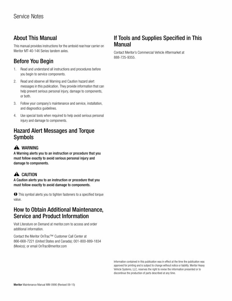
Maintenance Manual MM-0990
Amboid Rear Differential CarrierRear/Rear Carrier on MT-40-14X Series Tandem Drive AxlesRevised 09-15
Service Notes
Information contained in this publication was in effect at the time the publication was approved for printing and is subject to change without notice or liability. Meritor Heavy Vehicle Systems, LLC, reserves the right to revise the information presented or to discontinue the production of parts described at any time.
Meritor Maintenance Manual MM-0990 (Revised 09-15)
About This ManualThis manual provides instructions for the amboid rear/rear carrier on Meritor MT-40-14X Series tandem axles.
Before You Begin1. Read and understand all instructions and procedures before
you begin to service components.
2. Read and observe all Warning and Caution hazard alert messages in this publication. They provide information that can help prevent serious personal injury, damage to components, or both.
3. Follow your company’s maintenance and service, installation, and diagnostics guidelines.
4. Use special tools when required to help avoid serious personal injury and damage to components.
Hazard Alert Messages and Torque Symbols
WARNINGA Warning alerts you to an instruction or procedure that you must follow exactly to avoid serious personal injury and damage to components.
CAUTIONA Caution alerts you to an instruction or procedure that you must follow exactly to avoid damage to components.
@ This symbol alerts you to tighten fasteners to a specified torque value.
How to Obtain Additional Maintenance, Service and Product InformationVisit Literature on Demand at meritor.com to access and order additional information.
Contact the Meritor OnTrac™ Customer Call Center at 866-668-7221 (United States and Canada); 001-800-889-1834 (Mexico); or email [email protected]
If Tools and Supplies Specified in This ManualContact Meritor’s Commercial Vehicle Aftermarket at 888-725-9355.

pg. pg.
Contents
1 Section 1: Exploded View3 Section 2: Introduction
DescriptionAmboid Rear Differential Carrier
4 Stall-Testing Can Damage a Drive AxleUse of Traction ChainsIdentificationModel Number
6 Section 3: Removal and DisassemblyRemovalFasteners Secured with AdhesiveAxle Shafts
8 Differential Carrier from the Axle Housing9 Differential and Ring Gear from the Carrier12 Drive Pinion from the Carrier
14 Section 4: Prepare Parts for AssemblyClean, Dry and Inspect PartsClean Ground and Polished PartsClean Rough PartsClean Axle AssembliesDry Parts Immediately After Cleaning
15 Corrosion ProtectionPrevent Corrosion on Cleaned PartsInspectionInspect Parts
16 RepairRepair or Replace the Parts
17 Repair Welding on Axle HousingsRemovalFasteners Secured with AdhesivePrepare the Differential for ReassemblyCarrier-to-Housing Joint Sealing Procedure
18 InstallationFasteners
19 Applying Adhesive and Silicone Gasket Material20 Identification
Gear Sets21 Check for Mismatched Ratios on Tandem Axles
Gear Set Ratios Listed on the Identification TagsRotate the Forward Drive Shaft to Check the Gear Set Ratio
22 Gear Set Teeth Numbers Stamped on the Forward and Rear Axle Drive Pinions
23 Verify the Actual Gear Set RatiosInspectionYoke
24 Tire Matching for Tandem Axles
25 Section 5: Assembly and InstallationInstallation“Dry Fit” and “Final” Assembly and Installation ProceduresInstalling the Drive Pinion, Adjusting Pinion Depth and
Contact PatternDrive Pinion Shim Pack Thickness
26 Assembly“Dry Fit”Assembly of the Drive Pinion to Verify Shim Pack
28 InstallationDrive Pinion
29 AssemblyMain Differential and Ring Gear
31 Check the Rotating Resistance of the Differential Assembly32 Installation
“Dry Fit” Installation of the Main Differential Case and Ring Gear Assembly Into the Carrier
34 Adjustment of Pinion Shim Pack and Backlash for Contact Pattern
Ring Gear BacklashGear Set Tooth Contact Patterns
38 Installation“Final” Installation of the Drive Pinion and Bearing Preload
Adjustment40 “Final” Installation of the Main Differential Case and Ring
Gear Assembly Into the Carrier42 Adjustment
Differential Bearings Preload44 Ring Gear Runout45 Installation
Unitized Pinion Seal and Yoke47 Install the Differential Carrier into the Axle Housing48 Install the Axle Shafts
50 Section 6: LubricationLubrication
52 Section 7: SpecificationsFasteners
56 Section 8: Vehicle Towing InstructionsBefore Towing or Drive-Away
57 After Towing or Drive-Away
58 Section 9: Special ToolsSpecial ToolsHow to Make a Yoke Bar
59 Carrier Repair Stand Specifications60 Multiple Lip Seals (MLS) and Seal Drivers

1 Exploded View
1Meritor Maintenance Manual MM-0990 (Revised 09-15)
1 Exploded View
Figure 1.1
4007420a
14
28
33
2930
3231
34
45
46
47
48
49
50
51
52
35
33
30
42
40 41
44
43
2928
36
34
37
38
39
14
13
16
15
15
17
17
16
12
8
9
9
21
1920
18
13
1011
1
2
3
4
5
6
7
24
25
26
27
22
23
Item Description
1 Yoke Locknut
2 Flat Washer
3 Yoke
4 Deflector
5 Oil Seal Assembly
6 Bearing Cone
7 Bearing Cup
8 2.25-inch Capscrew
9 Hardened Washer
10 Tapered Dowel
11 Carrier Housing
12 1.75-inch Capscrew
13 Lock Plate
14 Capscrew
15 Washer
16 Bearing Cap Capscrew
17 Bearing Cap
18 Name Plate
19 Locknut
20 Thrust Screw
21 Drive Gear Thrust Block
22 Spacer
Item Description

1 Exploded View
2 Meritor Maintenance Manual MM-0990 (Revised 09-15)
23 Large Spacer
24 Drive Pinion Shims
25 Bearing Cup
26 Bearing Cone
27 Drive Pinion
28 Adjusting Ring
29 Bearing Cup
30 Bearing Cone
31 Case Half Capscrew
32 Differential Case Half
33 Ring Gear-to-Flange Half Capscrew
34 Ring Gear
35 Differential Washer
36 Side Gear
37 Thrust Washer
38 Pinion Gear
39 Differential Spider
40 Washer (If Equipped)
41 Nut (If Equipped)
42 Magnetic Plug
43 Magnets
44 Name Plate
45 Short Axle Shaft
46 Breather
47 Beather Hose
48 Magnetic Plug
49 Heat Indicator Plug
50 Fill Plug
51 Axle Housing
52 Long Axle Shaft
Item Description

2 Introduction
3Meritor Maintenance Manual MM-0990 (Revised 09-15)
2 IntroductionDescription
Amboid Rear Differential CarrierThe Meritor single-reduction amboid rear differential carrier is used on MT-40-14X tandem drive axles. Figure 2.1. The amboid design minimizes driveline angle configuration and places the drive pinion above the centerline, which helps to reduce vibration during operation.
The carrier is front-mounted into the axle housing and has an amboid drive pinion and ring gear set.
All bearings in the carrier are tapered roller bearings.
When the carrier operates, there is normal differential action between the wheels at all times.
Figure 2.1
Figure 2.1
TAPEREDROLLERBEARINGS
TAPEREDROLLERBEARING
BEVELDIFFERENTIALGEARS
AXLEHOUSING
TAPEREDROLLER
BEARING
CARRIER
AMBOIDDRIVE
PINIONAND RING
GEAR
4008099a

2 Introduction
4 Meritor Maintenance Manual MM-0990 (Revised 09-15)
Stall-Testing Can Damage a Drive AxleStall-testing is a procedure used to troubleshoot transmissions, evaluate vehicle performance, and test the service and park brakes.
During stall-testing, or any similar procedure, the drive axle input receives multiplied torque, which can exceed the specified torque rating. Excessive torque can damage a drive axle, which will affect axle performance and component life. A drive axle damaged by stall-testing will void Meritor’s warranty.
Call the Meritor OnTrac™ Customer Call Center at 866-OnTrac1 (668-7221) if you have questions regarding stall-testing.
Use of Traction ChainsMeritor recommends that if you are using traction chains, you should install chains on both tires on each side of all drive axles on the vehicle.
Identification
Model NumberAn identification tag is attached to the axle housing or the differential carrier. Figure 2.2 and Figure 2.3. Use the model number and the ratio number marked on the identification tag and the number on the carrier to obtain replacement parts.
Figure 2.2
Figure 2.3
Refer to Figure 2.4 for an explanation of the model number.
Figure 2.2
Model No. . . . . . . . . . . . . . . . . . . . Customer No. . . . . . . . . . . . . . . . .
Serial No. . . . . . . . . Plant . . . . . . . .Ratio . . . . . . . . . . . .
IDENTIFICATION TAG
LOCATION OF THE IDENTIFICATION TAG, OR STAMP NUMBER, FOR THE AXLES. LOCATION IS DETERMINED FROM THE LEFT DRIVER SIDE LOOKING TOWARD THE FRONT OF THE VEHICLE.
FRONT ENGINE DRIVE — RIGHT REAR, NEXT TO COVER
4008141a
AXLE IDENTIFICATION TAG INFORMATION
Figure 2.3
4008212a
CARRIERIDENTIFICATION TAG
CARRIER PART NO. CUSTOMER NO.SERIAL NO.RATIO
CARRIER PART NO.
CUSTOMER NO.
SERIAL NO.
RATIO

2 Introduction
5Meritor Maintenance Manual MM-0990 (Revised 09-15)
Figure 2.4
Figure 2.4
Meritor MS/MT-14X Current Drive Axle Model Nomenclature
M x - xx - x x x x x x x x x - x x x - x x x x
4007403b
Housing Wall0 = Cast1 = TBD2 = 0.31 in. (8 mm)3 = 0.37/0.39 in. (9.5/10.0 mm)4 = 0.43 in. (11 mm)5 = 0.50/0.51 in. (12.7/13.0 mm)6 = 0.56 in. (14.3 mm)7 = TBD8 = 0.63 in. (16 mm)9 = TBD
Carrier Type
GAWRxx = GAWR (000) Pounds or Tons
(dependent on mfg. location)
Axle Model Type*S = Single Rear (Solo)D = Fwd Rear w/IADN = Fwd Rear less IADP = Fwd Rear w/PumpR = Rear RearT = Tandem DriveZ = Tridem DriveC = CoachH = High EntryV = Fwd Rear w/no
thru shaft
M = Meritor
* For Front Drive Steer Axles,refer to page 6.
Specification NumberIncludes: TRACK, PARKINGBRAKE, OTHER.
Ratio 1Axle Type0 = No Carrier1 = Single Speed2 = Two Speed3 = Helical Double Reduction4 = Salisbury5 = Planetary Double Reduction6 = Planetary Hub Reduction7 = Portal8 = Bevel Hub Reduction9 = Single Speed with Torque Output Limited Engine
M S - 2 1 - 1 4 X 5 D B R N Q - 1 2 3 - 3 5 5
Carrier VariationA = Aluminum B = Aluminum/Ductile Amboid (Tandem Split)C = Ductile/Ductile Amboid (Tandem Split) D = Ductile Rear, HyboidE = Aluminum/Ductile (Tandem Split) F = Ductile Amboid/Ductile Hypoid (Tandem Split)H = Ductile Amboid/Spiral Bevel (Tandem Split) M = Ductile Rear, AmboidN = No CarrierR = Ductile Front Drive Axle Carrier, Right Hand
MFG LocationA = Australia/Asia/AfricaE = Europe N = North America S = South AmericaT = Telma Retarder (U.S.A.)
Brake TypeB = “B” Frame BrakeC = Air Disc BrakeD = Wedge Brake, Dual Air ChambersE = Wedge Brake, Dual Hydraulic CylindersF = Wedge Brake, Single Hydraulic CylinderG = DuraPark® Hydraulic DrumH = Quadraulic™ DiscK = EX+™ Air DiscL = Q+™ Cam BrakeN = NoneP = “P” Series Cam BrakeQ = “Q” Series Cam BrakeR = Cast+™ BrakeS = Wedge Brake, Single Air ChamberT = “T” Series Cam BrakeV = Simplex Air Cam BrakeW = “W” Series Cam BrakeZ = Non-Meritor Brake
Main Differential Nest TypeA = DCDL/Standard (Tandem Split)B = Special DifferentialC = Driver Controlled Differential Lock — DCDLD = DCDL/NoSPIN® (Tandem Split)E = Standard/DCDL (Tandem Split)F = Standard DifferentialG = Standard/NoSPIN® (Tandem Split)H = High Traction DifferentialJ = NoSPIN®/DCDL (Tandem Split)K = NoSPIN®/Standard (Tandem Split)L = No DifferentialN = NoSPIN®
Wheel End/Brake AttachmentA = Conventional Spindle/Conventional Brake E = Unitized Spindle/Conventional BrakeJ = Conventional Spindle/Integral BrakeL = Conventional L Spindle/Conventional Brake N = Unitized Spindle/Integral BrakeR = Conventional R Spindle/Conventional Brake S = Bolt on Conventional Spindle/ Conventional Brake
NOTE: The term “Tandem Split” refers to when there is a difference between theForward axle and Rear axle of the Tandemor Tridem axle set when the Tandem orTridem axle set part number is used. Thevalue to the left of the “/” references theForward axle, and the number to the rightof the “/” references the Rear axle. Forinformation related to the Middle axle of aTridem axle set part number, refer to theBills of Material.
Carrier size. Larger numbers indicate a higher GCW rated carrier; i.e., larger ring gear etc.

3 Removal and Disassembly
6 Meritor Maintenance Manual MM-0990 (Revised 09-15)
3 Removal and DisassemblyHazard Alert MessagesRead and observe all Warning and Caution hazard alert messages in this publication. They provide information that can help prevent serious personal injury, damage to components, or both.
WARNINGTo prevent serious eye injury, always wear safe eye protection when you perform vehicle maintenance or service.
Park the vehicle on a level surface. Block the wheels to prevent the vehicle from moving. Support the vehicle with safety stands. Do not work under a vehicle supported only by jacks. Jacks can slip and fall over. Serious personal injury and damage to components can result.
Use a brass or synthetic mallet for assembly and disassembly procedures. Do not hit steel parts with a steel hammer. Pieces of a part can break off. Serious personal injury and damage to components can result.
Removal
Fasteners Secured with AdhesiveIf it’s difficult to remove fasteners secured with Dri-Loc, Meritor specification 2297-T-4180 or Loctite 277 adhesive, use the following procedure.
CAUTIONWhen you remove fasteners secured with adhesive, slowly heat the fastener to 350°F (177°C). Do not exceed this temperature, or heat fasteners quickly. Damage to components can result.
1. Heat a fastener for three to five seconds only. Try to loosen the fastener with a wrench. Do not use an impact wrench or hit the fastener with a hammer.
2. Repeat Step 1 until you can remove the fastener.
Axle Shafts1. Wear safe eye protection.
2. Park the vehicle on a level surface and block the wheels to prevent the vehicle from moving.
3. Raise the end of the vehicle where the axle is mounted. Use a jack or other lifting tool, and place safety stands under each side of the axle.
4. Place jackstands under each spring seat of the axle to hold the vehicle in the raised position. Figure 3.1.
Figure 3.1
5. Remove the plug from the bottom of the axle housing and drain the lubricant from the assembly.
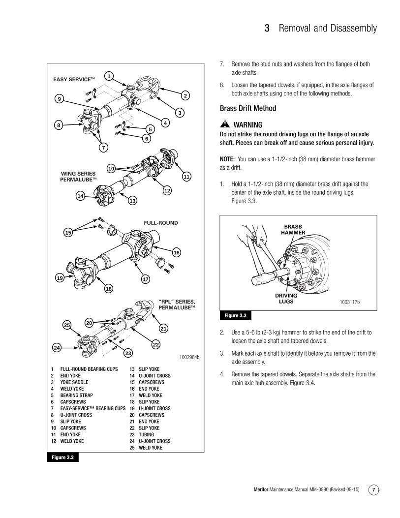
6. Disconnect the driveline universal joint from the pinion input yoke or flange on the carrier. Figure 3.2.
Figure 3.1
SAFETYSTANDS
1002983a
3 Removal and Disassembly
7Meritor Maintenance Manual MM-0990 (Revised 09-15)
Figure 3.2
7. Remove the stud nuts and washers from the flanges of both axle shafts.
8. Loosen the tapered dowels, if equipped, in the axle flanges of both axle shafts using one of the following methods.
Brass Drift Method
WARNINGDo not strike the round driving lugs on the flange of an axle shaft. Pieces can break off and cause serious personal injury.
NOTE: You can use a 1-1/2-inch (38 mm) diameter brass hammer as a drift.
1. Hold a 1-1/2-inch (38 mm) diameter brass drift against the center of the axle shaft, inside the round driving lugs. Figure 3.3.
Figure 3.3
2. Use a 5-6 lb (2-3 kg) hammer to strike the end of the drift to loosen the axle shaft and tapered dowels.
3. Mark each axle shaft to identify it before you remove it from the axle assembly.
4. Remove the tapered dowels. Separate the axle shafts from the main axle hub assembly. Figure 3.4.
Figure 3.2
1 FULL-ROUND BEARING CUPS2 END YOKE3 YOKE SADDLE4 WELD YOKE5 BEARING STRAP6 CAPSCREWS7 EASY-SERVICE™ BEARING CUPS8 U-JOINT CROSS9 SLIP YOKE10 CAPSCREWS11 END YOKE12 WELD YOKE
13 SLIP YOKE14 U-JOINT CROSS15 CAPSCREWS16 END YOKE17 WELD YOKE18 SLIP YOKE19 U-JOINT CROSS20 CAPSCREWS21 END YOKE22 SLIP YOKE23 TUBING24 U-JOINT CROSS25 WELD YOKE
12
13
11
14
10
7
8
6
45
1
2
3
9
16
15
17
18
19
1002984b
EASY SERVICETM
WING SERIESPERMALUBETM
FULL-ROUND
“RPL” SERIES,PERMALUBETM
2324
22
2021
25
Figure 3.3
BRASSHAMMER
DRIVINGLUGS 1003117b

3 Removal and Disassembly
8 Meritor Maintenance Manual MM-0990 (Revised 09-15)
Figure 3.4
5. Install a cover over the open end of each axle assembly hub where an axle shaft was removed.
Air Hammer Vibration Method
CAUTIONDo not use a chisel or wedge to loosen the axle shaft and tapered dowels, which can damage the axle shaft, gasket and seal, and axle hub.
1. Use a round hammer bit and an air hammer to loosen the tapered dowels and axle shaft.
2. Place the round hammer bit against the axle shaft between the hub studs. Operate the air hammer at alternate locations between the studs to loosen the tapered dowels and axle shaft from the hub. Figure 3.5.
Figure 3.5
3. Mark each axle shaft to identify it before you remove it from the axle assembly.
4. Remove the tapered dowels. Separate the axle shaft from the main axle hub assembly. Figure 3.4.
5. Install a cover over the open end of each axle assembly hub where an axle shaft was removed.
Differential Carrier from the Axle Housing1. Place a hydraulic roller jack under the differential carrier to
support the assembly. Figure 3.6.
Figure 3.6
2. Remove all but the top two carrier-to-housing capscrews or stud nuts and washers.
3. Loosen the top two carrier-to-housing fasteners, but leave them attached to the assembly. The fasteners will hold the carrier in the housing.
WARNINGUse a brass or synthetic mallet for assembly and disassembly procedures. Do not hit steel parts with a steel hammer. Pieces of a part can break off. Serious personal injury and damage to components can result.
4. Loosen the differential carrier in the axle housing. Use a leather mallet to hit the mounting flange of the carrier at several points.
5. After the carrier is loosened, remove the top two fasteners.
Figure 3.4
Figure 3.5
1002581c
TAPEREDDOWEL,
IF EQUIPPED
GASKET
STUD
SHAFTHUBAXLE
AXLESHAFT ORFLANGE
STUDNUT
WASHER
ROUND HAMMER BITBETWEEN HUB STUDS
1002987a
Figure 3.6
WOODBLOCK
ROLLERJACK 1002709d

3 Removal and Disassembly
9Meritor Maintenance Manual MM-0990 (Revised 09-15)
CAUTIONWhen you use a pry bar, be careful not to damage the carrier or housing flange. Damage to these surfaces will cause oil leaks.
6. Carefully remove the carrier from the axle housing using the hydraulic roller jack. Use a pry bar that has a round end to help remove the carrier from the housing. Take care that you don’t damage the carrier or housing flange with the pry bar.
NOTE: A carrier stand is available from SPX Kent-Moore. To obtain this tool, refer to the Service Notes page on the front inside cover of this manual.
7. Use a lifting tool to lift the differential carrier by the input yoke or flange. Do not lift the carrier by hand. Place the assembly in a carrier stand. Figure 3.7. Refer to Section 9 to build a stand.
Figure 3.7
Differential and Ring Gear from the Carrier1. Before you begin service procedures on the differential carrier,
inspect the gear set for damage.
� If the gear set isn’t damaged: You can reuse the gear set.
� If the gear set is damaged: Replace it with a new gear set.
2. Measure and record gear set backlash. Figure 3.8. Refer to Step 1 through Step 4 under Ring Gear Tooth Contact Pattern, Backlash in Section 5 for instructions. Adjust backlash to the original dimension when you install the gear set into the carrier during assembly procedures.
Figure 3.8
3. Loosen the jam nut on the thrust screw. Use a 12 mm allen-head wrench to loosen the thrust screw. Figure 3.9.
Figure 3.9
4. Rotate the differential carrier in the repair stand until the ring gear is at the TOP of the assembly.
5. Use a center punch and hammer to mark one carrier leg and bearing cap to correctly match the parts during carrier assembly. Figure 3.10.
Figure 3.7
REPAIRSTAND
DIFFERENTIALCARRIER
1002710f
Figure 3.8
Figure 3.9
DIALINDICATOR
1002722d
4000166cLoosen thrust screw 1/2 turn.

3 Removal and Disassembly
10 Meritor Maintenance Manual MM-0990 (Revised 09-15)
Figure 3.10
6. Remove the capscrews and lock plates that secure the bearing adjusting rings in position. Figure 3.11.
Figure 3.11
7. Remove the two capscrews and washers that secure the two bearing caps onto the carrier. Figure 3.12.
Figure 3.12
8. Remove the bearing caps and bearing adjusting rings from the carrier. Figure 3.13.
Figure 3.13
9. Use a lifting strap to lift the main differential and ring gear assembly from the carrier. Place the assembly onto a work bench. Figure 3.14.
Figure 3.14
Figure 3.10
Figure 3.11
BEARINGCAP
CARRIERLEG
1002994b
MATCHMARKS
LOCKPLATE
THREADED HOLES IN CAP
1003105f
Figure 3.12
Figure 3.13
Figure 3.14
1002996c
BEARINGCAP
BEARINGCAP
BEARINGADJUSTING
RING
1002748e
1002749h
3 Removal and Disassembly
11Meritor Maintenance Manual MM-0990 (Revised 09-15)
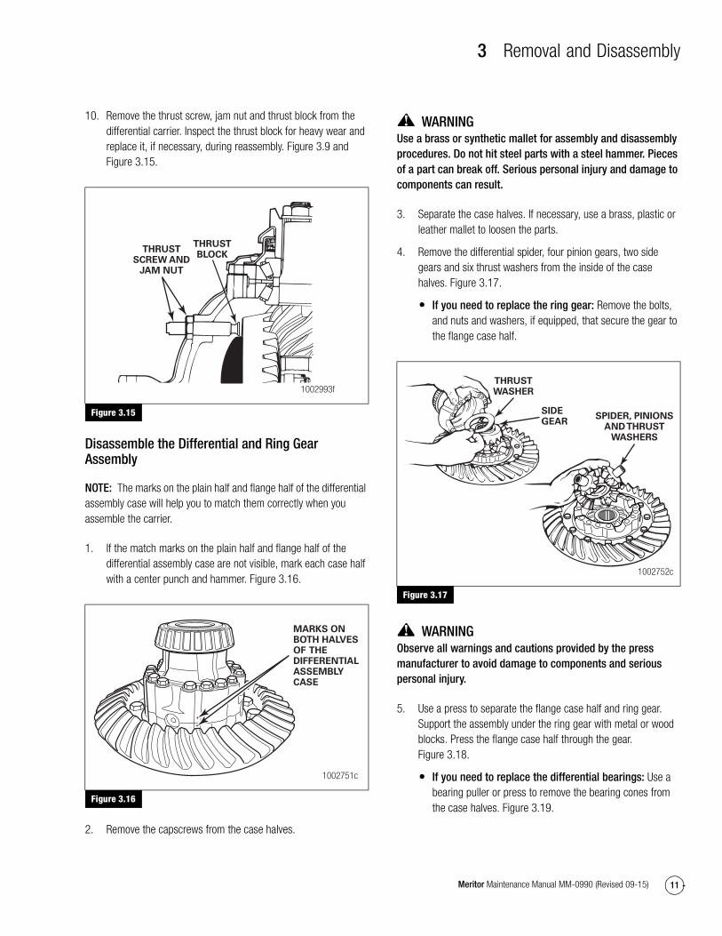
10. Remove the thrust screw, jam nut and thrust block from the differential carrier. Inspect the thrust block for heavy wear and replace it, if necessary, during reassembly. Figure 3.9 and Figure 3.15.
Figure 3.15
Disassemble the Differential and Ring Gear Assembly
NOTE: The marks on the plain half and flange half of the differential assembly case will help you to match them correctly when you assemble the carrier.
1. If the match marks on the plain half and flange half of the differential assembly case are not visible, mark each case half with a center punch and hammer. Figure 3.16.
Figure 3.16
2. Remove the capscrews from the case halves.
WARNINGUse a brass or synthetic mallet for assembly and disassembly procedures. Do not hit steel parts with a steel hammer. Pieces of a part can break off. Serious personal injury and damage to components can result.
3. Separate the case halves. If necessary, use a brass, plastic or leather mallet to loosen the parts.
4. Remove the differential spider, four pinion gears, two side gears and six thrust washers from the inside of the case halves. Figure 3.17.
� If you need to replace the ring gear: Remove the bolts, and nuts and washers, if equipped, that secure the gear to the flange case half.
Figure 3.17
WARNINGObserve all warnings and cautions provided by the press manufacturer to avoid damage to components and serious personal injury.
5. Use a press to separate the flange case half and ring gear. Support the assembly under the ring gear with metal or wood blocks. Press the flange case half through the gear. Figure 3.18.
� If you need to replace the differential bearings: Use a bearing puller or press to remove the bearing cones from the case halves. Figure 3.19.
Figure 3.15
Figure 3.16
THRUSTSCREW AND
JAM NUT
1002993f
THRUSTBLOCK
MARKS ONBOTH HALVESOF THEDIFFERENTIALASSEMBLYCASE
1002751c
Figure 3.17
THRUSTWASHER
SIDEGEAR
SPIDER, PINIONSAND THRUST
WASHERS
1002752c

3 Removal and Disassembly
12 Meritor Maintenance Manual MM-0990 (Revised 09-15)
Figure 3.18
Figure 3.19
Drive Pinion from the Carrier1. Fasten a flange bar to the input yoke or flange. When you
remove the nut, the bar will hold the drive pinion in position. Refer to Section 9 for instructions to make a yoke bar. Figure 3.20.
Figure 3.20
2. Remove the nut and washer, if equipped, from the drive pinion. Figure 3.20.
3. Remove the yoke or flange bar.
CAUTIONIf the yoke and flange are difficult to remove from the drive pinion during disassembly, use a puller. Do not use a hammer or mallet, which can damage components and affect driveline alignment and end play.
4. Remove the yoke or flange from the drive pinion. If the yoke or flange is tight on the pinion, use a puller. Figure 3.21.
Figure 3.21
NOTE: Always use a new oil seal during reassembly. Don’t reuse a seal that’s been removed.
5. Use appropriate prying tools to remove the unitized oil seal from the carrier. Place the blades of the prying tools under the flange to remove the oil seal. Figure 3.22.
Figure 3.18
Figure 3.19
Figure 3.20
FLANGECASEHALF
PRESS
PLATE
1003002d
SUPPORTS
PULLER
PRESS
1002750c
4000167b
FLANGE/YOKE
BAR
Figure 3.21
1003348d
FLANGEPULLER
YOKEPULLER

3 Removal and Disassembly
13Meritor Maintenance Manual MM-0990 (Revised 09-15)
Figure 3.22
WARNINGObserve all warnings and cautions provided by the press manufacturer to avoid damage to components and serious personal injury.
6. Place the carrier assembly in a press with the threaded end of the pinion shaft pointing UP. Figure 3.23.
Figure 3.23
7. Press the pinion shaft out of the outer bearing cone. Do not let the pinion shaft drop to the ground after being pressed out. Figure 3.23.
8. Remove the outer bearing cone from the carrier.
� If you need to replace the pinion bearings: Use a suitable puller to remove the inner and outer bearing cups from the carrier.
9. Remove the shims from the carrier.
� If the shims are in good condition: Keep the shims together for use when the carrier is assembled.
� If the shims are to be discarded because of damage: First measure the total thickness of the pack. Make a note of the dimension. You will need the dimension to calculate the depth of the drive pinion in the carrier when the gear set is installed.
10. Remove the bearing spacer and variable spacer from the pinion shaft. Figure 3.24.
� If you need to replace the pinion bearings: Use a press or bearing puller to remove the inner bearing cone from the drive pinion. The puller must fit under the inner race of the cone to remove the cone correctly without damage. Figure 3.25.
Figure 3.24
Figure 3.25
Figure 3.22
Figure 3.23
4000168b
4000169c
Figure 3.24
Figure 3.25
4000170a
SPACERS
SUPPORTS
INNERBEARING
CONE
PRESSDRIVEPINION
BEARINGPULLER
1003012d

4 Prepare Parts for Assembly
14 Meritor Maintenance Manual MM-0990 (Revised 09-15)
4 Prepare Parts for AssemblyHazard Alert MessagesRead and observe all Warning and Caution hazard alert messages in this publication. They provide information that can help prevent serious personal injury, damage to components, or both.
WARNINGTo prevent serious eye injury, always wear safe eye protection when you perform vehicle maintenance or service.
Solvent cleaners can be flammable, poisonous and cause burns. Examples of solvent cleaners are carbon tetrachloride, and emulsion-type and petroleum-base cleaners. Read the manufacturer’s instructions before using a solvent cleaner, then carefully follow the instructions. Also follow the procedures below.
� Wear safe eye protection.
� Wear clothing that protects your skin.
� Work in a well-ventilated area.
� Do not use gasoline or solvents that contain gasoline. Gasoline can explode.
� You must use hot solution tanks or alkaline solutions correctly. Read the manufacturer’s instructions before using hot solution tanks and alkaline solutions. Then carefully follow the instructions.
Take care when you use Loctite adhesive to avoid serious personal injury. Read the manufacturer’s instructions before using this product. Follow the instructions carefully to prevent irritation to the eyes and skin. If Loctite adhesive material gets into your eyes, follow the manufacturer’s emergency procedures. Have your eyes checked by a physician as soon as possible.
When you apply some silicone gasket materials, a small amount of acid vapor is present. To prevent serious personal injury, ensure that the work area is well-ventilated. Read the manufacturer’s instructions before using a silicone gasket material, then carefully follow the instructions. If a silicone gasket material gets into your eyes, follow the manufacturer’s emergency procedures. Have your eyes checked by a physician as soon as possible.
Clean, Dry and Inspect Parts
Clean Ground and Polished Parts1. Use a cleaning solvent to clean ground or polished parts or
surfaces. Kerosene or diesel fuel oil can be used for this purpose. DO NOT USE GASOLINE.
2. Use a tool with a flat blade, if required, to remove sealant material from parts. Be careful not to damage the polished or smooth surfaces.
CAUTIONDo not use hot solution tanks or water and alkaline solutions to clean ground or polished parts. Damage to parts can result.
3. Do not clean ground or polished parts with water or steam. Do not immerse ground or polished parts in a hot solution tank or use strong alkaline solutions for cleaning, or the smooth sealing surface may be damaged.
Clean Rough Parts1. Clean rough parts with the same method as cleaning ground
and polished parts.
2. Rough parts can be cleaned in hot solution tanks with a weak or diluted alkaline solution.
3. Parts must remain in hot solution tanks until heated and completely cleaned.
4. Parts must be washed with water until all traces of the alkaline solution are removed.
Clean Axle Assemblies1. A complete axle assembly can be steam cleaned on the
outside to remove dirt.
2. Before the axle is steam cleaned, close or place a cover over all openings in the axle assembly. Examples of openings are breathers or vents in air chambers.
Dry Parts Immediately After Cleaning
All Parts Except Bearings
Use soft, clean paper, cloth rags or compressed air to dry parts immediately after cleaning.

4 Prepare Parts for Assembly
15Meritor Maintenance Manual MM-0990 (Revised 09-15)
Bearings
CAUTIONUse soft, clean paper or cloth rags to dry bearings immediately after cleaning. Do not use compressed air, which can damage the bearings when they are rotated and dried.
Use soft, clean paper or cloth rags to dry bearings immediately after cleaning. Do not use compressed air.
Corrosion Protection
Prevent Corrosion on Cleaned Parts1. Apply axle lubricant to cleaned and dried parts that are not
damaged and are to be assembled.
2. To store parts, apply a special material that prevents corrosion to all surfaces. Wrap cleaned parts in a special paper that will protect the parts from moisture and prevent corrosion.
Inspection
Inspect PartsIt is very important to inspect all parts carefully and completely before the axle or carrier is assembled. Check all parts for wear and replace damaged parts.
1. Inspect the cup, cone, rollers and cage of all tapered roller bearings in the assembly. If any of the following conditions exist, replace the bearing.
� The center of the large-diameter end of the rollers is worn level with or below the outer surface. Figure 4.1.
� The radius at the large-diameter end of the rollers is worn to a sharp edge. Figure 4.1.
� There is a visible roller groove in the cup or cone inner race surfaces. The groove can be seen at the small- or large-diameter end of both parts. Figure 4.2.
� There are deep cracks or breaks in the cup, cone inner race or roller surfaces. Figure 4.2.
� There are bright wear marks on the outer surface of the roller cage. Figure 4.3.
� There is damage on the rollers and on the surfaces of the cup and cone inner race that touch the rollers. Figure 4.4.
� There is damage on the cup and cone inner race surfaces that touch the rollers. Figure 4.5.
Figure 4.1
Figure 4.2
Figure 4.3
Figure 4.1
Figure 4.2
Figure 4.3
1003017b
WORN RADIUS
WORN SURFACE
1003018b
WEARGROOVES
CRACK
1003019aWEAR MARKS

4 Prepare Parts for Assembly
16 Meritor Maintenance Manual MM-0990 (Revised 09-15)
Figure 4.4
Figure 4.5
CAUTIONA drive pinion and ring gear is machined as a matched set. When you replace either a drive pinion or a ring gear, you must replace both parts as a matched set. Do not mix old and new parts. Damage to components can result.
2. Inspect pinions and gears for wear or damage. Replace pinions and gears that are worn or damaged.
CAUTIONWhen you need to replace either a thrust washer, differential side gear or pinion gear, you must replace all of these parts with a new set. Do not mix old and new parts. Damage to components can result.
3. Inspect the following main differential assembly parts for wear or stress. Replace parts that are damaged. Figure 4.6.
� Inside surfaces of both case halves
� Both surfaces of all thrust washers
� The four trunnion legs of the spider
� Teeth and splines of both differential side gears
� Teeth, bore and spherical backface of all differential pinions
Figure 4.6
4. Inspect the axle shafts for wear and cracks at the flange, shaft and splines. Replace the axle shafts, if required.
Repair
Repair or Replace the Parts
NOTE: Threads must be without damage and clean so that accurate adjustments and correct torque values can be applied to fasteners and parts.
1. Replace any fastener if corners of the head are worn.
2. Replace the washers if damaged.
3. Replace the gaskets, oil seals or grease seals at the time of axle or carrier repair.
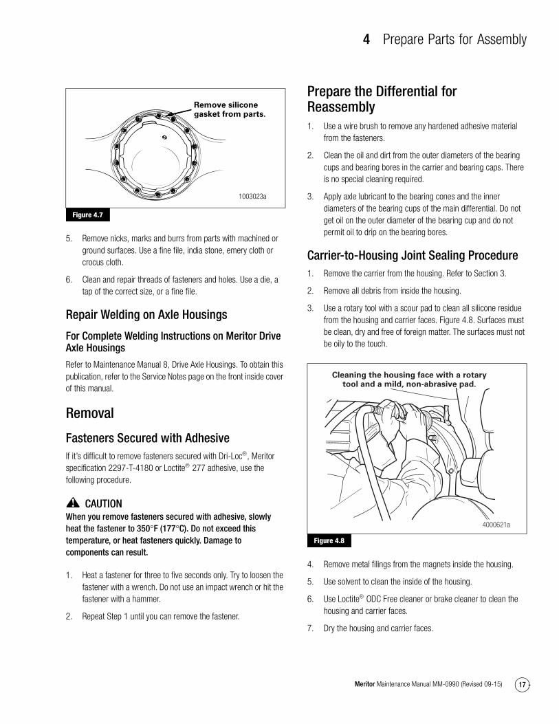
4. Clean the parts and apply new silicone gasket material where required when the axle or carrier is assembled. Figure 4.7.
Figure 4.4
Figure 4.5
1003020a
ETCHING AND PITTING
1003021b
SPALLING AND FLAKING
Figure 4.6
1003022i
DIFFERENTIALCASE HALVES
DIFFERENTIALGEAR NEST ASSEMBLY
Inspectinsidesurfaces.
PINION ANDTHRUSTWASHER
SIDE GEARAND THRUST
WASHER
Inspect.
Inspect.
SPIDER OR CROSS
Inspect.
4 Prepare Parts for Assembly
17Meritor Maintenance Manual MM-0990 (Revised 09-15)
Figure 4.7
5. Remove nicks, marks and burrs from parts with machined or ground surfaces. Use a fine file, india stone, emery cloth or crocus cloth.
6. Clean and repair threads of fasteners and holes. Use a die, a tap of the correct size, or a fine file.
Repair Welding on Axle Housings
For Complete Welding Instructions on Meritor Drive Axle Housings
Refer to Maintenance Manual 8, Drive Axle Housings. To obtain this publication, refer to the Service Notes page on the front inside cover of this manual.
Removal
Fasteners Secured with AdhesiveIf it’s difficult to remove fasteners secured with Dri-Loc, Meritor specification 2297-T-4180 or Loctite 277 adhesive, use the following procedure.
CAUTIONWhen you remove fasteners secured with adhesive, slowly heat the fastener to 350°F (177°C). Do not exceed this temperature, or heat fasteners quickly. Damage to components can result.
1. Heat a fastener for three to five seconds only. Try to loosen the fastener with a wrench. Do not use an impact wrench or hit the fastener with a hammer.
2. Repeat Step 1 until you can remove the fastener.
Prepare the Differential for Reassembly1. Use a wire brush to remove any hardened adhesive material
from the fasteners.
2. Clean the oil and dirt from the outer diameters of the bearing cups and bearing bores in the carrier and bearing caps. There is no special cleaning required.
3. Apply axle lubricant to the bearing cones and the inner diameters of the bearing cups of the main differential. Do not get oil on the outer diameter of the bearing cup and do not permit oil to drip on the bearing bores.
Carrier-to-Housing Joint Sealing Procedure1. Remove the carrier from the housing. Refer to Section 3.
2. Remove all debris from inside the housing.
3. Use a rotary tool with a scour pad to clean all silicone residue from the housing and carrier faces. Figure 4.8. Surfaces must be clean, dry and free of foreign matter. The surfaces must not be oily to the touch.
Figure 4.8
4. Remove metal filings from the magnets inside the housing.
5. Use solvent to clean the inside of the housing.
6. Use Loctite ODC Free cleaner or brake cleaner to clean the housing and carrier faces.
7. Dry the housing and carrier faces.
Figure 4.7
Remove siliconegasket from parts.
1003023a
Figure 4.8
Cleaning the housing face with a rotarytool and a mild, non-abrasive pad.
4000621a

4 Prepare Parts for Assembly
18 Meritor Maintenance Manual MM-0990 (Revised 09-15)
CAUTIONNew capscrew kits have blue Dri-Loc STS threadlocker, an equivalent to Loctite 242 threadlocker, applied to the capscrews. Do not remove the blue Dri-Loc STS threadlocker from the capscrews. Damage to components can result.
8. If you reuse the carrier-to-housing capscrews, use a rotary wire brush to remove any threadlocker material and clean the capscrew threads. Use a clean cloth to wipe the threads.
9. Use a tap of the appropriate thread size and class to clean the internal threads in the housing.
CAUTIONApply silicone gasket material in a continuous 0.25-inch (6 mm) bead to the housing face. If you use more than this amount, gasket material can break off and plug lubrication passages. Damage to components can result.
10. Apply a 0.25-inch (6 mm) bead of Loctite 5699 silicone gasket material to the housing face. Do not use ThreeBond 1216E silicone products. Figure 4.9.
Figure 4.9
11. Install two long studs in the housing to guide the carrier into the housing. Tighten the studs until there are no exposed threads.
12. Immediately install the carrier into the housing to enable the silicone gasket material to compress evenly between the faces. If using a new capscrew kit with blue Dri-Loc STS pre-applied threadlocker, skip the next step.
13. Apply a 0.125-inch (3 mm) bead of Loctite 242 threadlocker around the capscrew threads approximately 0.25-inch (6 mm) from the end. Apply a 0.125-inch (3 mm) bead of Loctite 242 threadlocker across the length of the threads. Figure 4.10.
Figure 4.10
14. Install the capscrews. Use a crossing pattern to tighten the capscrews evenly. The capscrews must be tightened within 10 minutes of initial application of Loctite 242 threadlocker.
� Tighten the 5/8-inch capscrews to 210-240 lb-ft (285-325 N�m). @
15. Wait a minimum of 60 minutes before filling the assembly with lubricant. Refer to Section 6.
Installation
Fasteners
New Fasteners with Pre-Applied Adhesive
NOTE: No drying time is required for fasteners with pre-applied adhesive.
1. Use a wire brush to clean oil and dirt from threaded holes.
2. Install new fasteners with pre-applied adhesive to assemble parts. Do not apply adhesives or sealants to fasteners with pre-applied adhesive, or to fastener holes.
3. Tighten fasteners to the required torque value for that size fastener.
Figure 4.9
0.25" (6 MM)DIAMETER SILICONE
GASKET BEAD 4004435a
Figure 4.10
0.25" (6 MM)
4000623b
360˚ LOCTITE® BEAD
LOCTITE® 242 THREADLOCKER APPLICATION
4 Prepare Parts for Assembly
19Meritor Maintenance Manual MM-0990 (Revised 09-15)
Original or Used Fasteners Using Meritor Liquid Adhesive 2297-M-5213, Loctite 277 or 270 Adhesive, or Equivalent
WARNINGTake care when you use Loctite adhesive to avoid serious personal injury. Read the manufacturer’s instructions before using this product. Follow the instructions carefully to prevent irritation to the eyes and skin.
1. Use a wire brush to clean the oil, dirt and old adhesive from all threads and threaded holes.
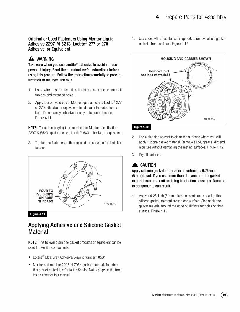
2. Apply four or five drops of Meritor liquid adhesive, Loctite 277 or 270 adhesive, or equivalent, inside each threaded hole or bore. Do not apply adhesive directly to fastener threads. Figure 4.11.
NOTE: There is no drying time required for Meritor specification 2297-K-5523 liquid adhesive, Loctite 680 adhesive, or equivalent.
3. Tighten the fasteners to the required torque value for that size fastener.
Figure 4.11
Applying Adhesive and Silicone Gasket Material
NOTE: The following silicone gasket products or equivalent can be used for Meritor components.
� Loctite Ultra Grey Adhesive/Sealant number 18581
� Meritor part number 2297-H-7054 gasket material. To obtain this gasket material, refer to the Service Notes page on the front inside cover of this manual.
1. Use a tool with a flat blade, if required, to remove all old gasket material from surfaces. Figure 4.12.
Figure 4.12
2. Use a cleaning solvent to clean the surfaces where you will apply silicone gasket material. Remove all oil, grease, dirt and moisture without damaging the mating surfaces. Figure 4.12.
3. Dry all surfaces.
CAUTIONApply silicone gasket material in a continuous 0.25-inch (6 mm) bead. If you use more than this amount, the gasket material can break off and plug lubrication passages. Damage to components can result.
4. Apply a 0.25-inch (6 mm) diameter continuous bead of the silicone gasket material around one surface. Also apply the gasket material around the edge of all fastener holes on that surface. Figure 4.13.
Figure 4.11
1003025a
FOUR TOFIVE DROPS
ON BORETHREADS
Figure 4.12
Remove oldsealant material.
HOUSING AND CARRIER SHOWN
1003027e

4 Prepare Parts for Assembly
20 Meritor Maintenance Manual MM-0990 (Revised 09-15)
Figure 4.13
5. Assemble the components immediately to permit the silicone gasket material to compress evenly between the parts. Tighten fasteners to the required torque value for that size fastener. Refer to Table K in Section 7.
6. Wait 20 minutes before filling the assembly with the correct lubricant. Refer to Section 6.
Identification
Gear SetsRefer to the following examples for information on identifying gear sets with matched parts. Always check the match numbers to verify that the gear set you will install has matched parts. Figure 4.14.
Figure 4.14
Examples
Gear Set
Gear Set Tooth Combination Number
Gear Set Match Number
NOTE: Meritor drive pinions and ring gears are only available as matched sets. Each gear in a set has an alphanumeric match number.
Pinion Cone Variation Number
NOTE: Don’t use the pinion cone variation number when you check for a matched gear set. Use this number when you adjust the pinion depth in the carrier. Refer to Section 5.
Figure 4.13
Figure 4.14
1 PART NUMBER, TOOTH COMBINATION NUMBER, GEAR SET MATCH NUMBER, PINION CONE VARIATION NUMBER
2 PART NUMBER, TOOTH COMBINATION NUMBER3 GEAR SET MATCH NUMBER, PINION CONE VARIATION NUMBER4 PART NUMBER, TOOTH COMBINATION NUMBER, GEAR SET MATCH
NUMBER5 PART NUMBER, TOOTH COMBINATION NUMBER, GEAR SET MATCH
NUMBER
0.25" (6 MM)DIAMETER SILICONE
GASKET BEAD 1003028f
1003031c
ALTERNATE LOCATIONS
Part Number Location
Conventional ring gear
XXXXX, XXXXXK2, XXXXXK3, XXXXXK4, XXXXXK5
On the front face or outer diameter
Conventional drive pinion
XXXXX, XXXXXK2, XXXXXK3, XXXXXK4, XXXXXK5
At the end at threads
Gear Set TeethDrive Pinion Location
Ring Gear Location
5-37 = gear set has a five-tooth drive pinion and a 37-tooth ring gear
At the end at threads
On the front face or outer diameter
Match NumberDrive Pinion Location
Ring Gear Location
M29 At the end of the gear head
On the front face or outer diameter

4 Prepare Parts for Assembly
21Meritor Maintenance Manual MM-0990 (Revised 09-15)
Check for Mismatched Ratios on Tandem AxlesFor a tandem axle pair to function correctly, the forward and rear axles must operate with axle ratios within one percent. A mismatched tandem axle pair can cause carrier overheating, gear set wear, metal debris to collect on the magnetic drain plug, carrier lubricant additive depletion, excessive inter-axle differential wear and noise.
To determine if the tandem axle ratios operate within allowable limits, refer to one of the following procedures. Perform the procedure that will work best for the vehicle you are servicing.
Gear Set Ratios Listed on the Identification Tags1. Locate the identification tags attached to the forward and rear
axle differential carriers. Figure 4.15.
Figure 4.15
2. Compare the axle ratios shown on the tags. To operate correctly, the axle ratios for both axles must be within one percent of each other. To calculate the percentage difference between the axle ratios, refer to the equation in Table A.
Table A:
� If the axle ratios shown on the identification tags are not within one percent of each other: Refer to the vehicle manufacturer for further information.
Rotate the Forward Drive Shaft to Check the Gear Set Ratio
WARNINGPark the vehicle on a level surface. Block the wheels to prevent the vehicle from moving. Support the vehicle with safety stands. Do not work under a vehicle supported only by jacks. Jacks can slip and fall over. Serious personal injury and damage to components can result.
1. Park the vehicle on a level surface.
2. Engage the inter-axle differential and shift the transmission into NEUTRAL.
3. Block the wheels to prevent the vehicle from moving.
4. Use a jack to raise the vehicle until all the tandem drive axle wheels clear the ground. Support the vehicle with safety stands.
5. Mark the forward and rear tires at identical relative positions. Figure 4.16.
Figure 4.16
Pinion Cone (PC) Variation Number
Drive Pinion Location
Ring Gear Location
PC+3
+2
+0.01 mm
PC–5
–1
–0.02 mm
At the end of the pinion gear head
On the outer diameter
Figure 4.15
1 FORWARD2 REAR
1003452c
CARRIER PART NO.
CUSTOMER NO.
SERIAL NO.
RATIO
CARRIER PART NO. CUSTOMER NO.SERIAL NO.RATIO
1 2
Larger Ratio – Smaller Ratio X 100 =
Percentage Difference Between Axle Ratios
Smaller Ratio
Figure 4.16
MARKSMARKS 1003453a

4 Prepare Parts for Assembly
22 Meritor Maintenance Manual MM-0990 (Revised 09-15)
6. Turn the forward drive shaft in one direction by hand until the forward tire completes two rotations. Figure 4.17. The forward tire must rotate two times only. If the forward tire rotates more than or less than two rotations, the angle measurements you make in Step 7 will be inaccurate.
Figure 4.17
7. Note the positions of the tire marks you previously made. On a correctly matched tandem axle gear set, both tire marks will be within ± 3.6 degrees of each other. Figure 4.18.
� If the positions of the tire marks are more than 3.6 degrees from each other: Refer to the vehicle manufacturer for further information.
Figure 4.18
8. Remove the safety stands and lower the vehicle.
Gear Set Teeth Numbers Stamped on the Forward and Rear Axle Drive PinionsWhen the inter-axle driveline or differential carrier is removed for service, you can check the gear set teeth numbers stamped on the forward and rear axle drive pinions.
WARNINGPark the vehicle on a level surface. Block the wheels to prevent the vehicle from moving. Support the vehicle with safety stands. Do not work under a vehicle supported only by jacks. Jacks can slip and fall over. Serious personal injury and damage to components can result.
1. Park the vehicle on a level surface.
2. Block the wheels to prevent the vehicle from moving.
To Identify the Gear Teeth Number on the Rear Axle Drive Pinion
1. Remove the inter-axle drive shaft. Refer to the vehicle manufacturer’s procedures.
2. Identify and record the gear set teeth numbers stamped on the end of the rear axle drive pinion. Figure 4.19.
Figure 4.19
3. Calculate the gear set ratio by dividing the larger number by the smaller number. Figure 4.19.
Compare Both Gear Set Ratios
1. Both ratios must be within one percent of each other. To calculate the percentage difference between the axle ratios, refer to the equation in Table A.
Figure 4.17
Figure 4.18
Rotate two full turnsof forward tire.
1003454b
3.6 3.6
If the mark appears inthe shaded area, the tandem
gear set is incorrectly matched.
If the mark appears inthis area, the tandem axle
gear set is correctly matched.
1003455a
Figure 4.19
1003457cLARGER NUMBER
SMALLER NUMBER= GEAR SET RATIO
10 47-

4 Prepare Parts for Assembly
23Meritor Maintenance Manual MM-0990 (Revised 09-15)
� If the axle ratios shown on the identification tags are not within one percent of each other: Refer to the vehicle manufacturer for further information.
2. Install the inter-axle drive shaft. Refer to the vehicle manufacturer’s procedures.
3. Remove the safety stands and lower the vehicle.
Verify the Actual Gear Set RatiosYou can check the actual gear set ratios when you remove the differential carriers from the axle housings for service or repair. Refer to the following procedure to calculate the actual gear set ratios.
1. Count the number of ring gear teeth. Figure 4.20.
Figure 4.20
2. Count the number of pinion gear teeth. Figure 4.20.
3. Divide the number of ring gear teeth by the number of pinion gear teeth to determine the actual gear set ratio for each axle. Figure 4.20.
4. Calculate the percentage difference between the gear set ratios using the equation in Table A. All ratios must match within one percent.
� If the actual gear set ratios are not within one percent of each other: Refer to the vehicle manufacturer for further information.
Inspection
YokeAll current Meritor axles feature helical splines at the yoke interface. This feature provides a tight fit between the yoke and input shaft, output shaft and pinion shaft. For the axle to operate correctly, the input shaft, output shaft and pinion shaft must fit tightly to the corresponding yoke.
Check for Yoke Wear
WARNINGPark the vehicle on a level surface. Block the wheels to prevent the vehicle from moving. Support the vehicle with safety stands. Do not work under a vehicle supported only by jacks. Jacks can slip and fall over. Serious personal injury and damage to components can result.
1. Park the vehicle on a level surface. Block the wheels to prevent the vehicle from moving.
2. Use a jack to raise the vehicle so that the wheels to be serviced are off the ground. Support the vehicle with safety stands.
3. Remove the driveline.
4. Remove the input, output or pinion shaft nut.
5. Attempt to remove the yoke by hand.
� If you can remove the yoke by hand: The yoke is worn. Replace the yoke.
6. Use a correct yoke puller tool to remove the yoke.
Check for a Tight-Fit Condition
NOTE: You can check for a tight-fit condition when you install any serviceable yoke.
1. Attempt to install the yoke by hand.
� If the yoke bottoms out against the adjacent bearing: Replace the yoke.
2. Use a correct yoke installation tool to install the yoke.
3. As you install the yoke, you should detect resistance between the yoke and shaft.
� If you do not detect resistance between the yoke and shaft: Replace the yoke.
Figure 4.20
RING GEAR TEETHPINION GEAR TEETH
= ACTUALGEAR SET RATIO
PINIONGEAR TEETH
RINGGEAR
TEETH
4008210a

4 Prepare Parts for Assembly
24 Meritor Maintenance Manual MM-0990 (Revised 09-15)
4. Install and tighten the input, output or pinion shaft nut to the correct torque. Refer to Section 7.
5. Install the driveline.
6. Remove the safety stands.
7. Lower the vehicle.
Tire Matching for Tandem Axles
CAUTIONUnmatched tires on tandem drive units will cause tire wear and scuffing and possible damage to the drive units. Meritor recommends that the tires be matched to within 0.125-inch (3.18 mm) of the same rolling radius, 0.75-inch (19.05 mm) of the same rolling circumference.
The four largest tires should never be installed onto one driving axle or the four smallest tires onto the other driving axle. Such tire mounting will cause an inter-axle fight, unusually high axle lubricant temperatures that result in premature lubricant breakdown and possible costly axle service.
In addition to matching individual tire rolling radii or rolling circumference, Meritor recommends matching, as nearly as possible, the total tire circumference of one driving axle to the total tire circumference of the other driving axle. This will usually result in satisfactory tandem axle lubricant temperatures that lengthen drive unit service with higher tire mileage.
Park the vehicle on a level surface. The vehicle must carry a correctly distributed rated capacity load. All the tires must be the same size. Measure new tires to verify that they will be correctly matched.
1. Inflate all tires to the same pressure.
2. Carefully measure the rolling circumference of each tire with a steel tape.
3. Mark the size on each tire with chalk and arrange the tires in order of size, largest to smallest.
4. Mount the two largest tires onto one side of one axle and mount the two smallest onto the opposite side of the same axle.
5. Mount the four other tires onto the other axle in the same manner.
6. Test run the vehicle to gather accurate rear axle lubricant temperature readings on the two axle lubricant temperature gauges.
7. Vary tire air pressure within the tire manufacturer’s recommended range so the lubricant temperature of both axles is within 30°F or 17°C of each other and not in excess of 250°F (121°C). This will usually result in uniform tire loading and good tire life.
5 Assembly and Installation
25Meritor Maintenance Manual MM-0990 (Revised 09-15)
5 Assembly and InstallationHazard Alert MessagesRead and observe all Caution and Warning safety alerts below and those that precede instructions or procedures you will perform.
WARNINGTo prevent serious eye injury, always wear safe eye protection when you perform vehicle maintenance or service.
Take care when you use Loctite adhesive to avoid serious personal injury. Read the manufacturer’s instructions before using this product. Follow the instructions carefully to prevent irritation to the eyes and skin. If Loctite adhesive material gets into your eyes, follow the manufacturer’s emergency procedures. Have your eyes checked by a physician as soon as possible.
Observe all warnings and cautions provided by the press manufacturer to avoid damage to components and serious personal injury.
To avoid serious personal injury and damage to components, take care when using lifting devices during service and maintenance procedures. Inspect a lifting strap to ensure that it is not damaged. Do not subject the lifting straps to shocks or drop-loading.
Installation
“Dry Fit” and “Final” Assembly and Installation ProceduresCorrect assembly of the carrier requires a “dry fit” installation of the drive pinion and ring gear to determine the correct drive pinion shim pack thickness. The carrier is then disassembled and reassembled using the spacers and adjusted shim pack. If the drive pinion is correctly adjusted, perform the “final” installation steps to complete the installation.
Installing the Drive Pinion, Adjusting Pinion Depth and Contact PatternThe procedure in this manual is to perform a “dry fit” installation of the pinion, bearings and calculated shim pack into the case WITHOUT the two spacers. You must also install the ring gear and set the backlash to 0.012-inch (0.3 mm). After you check and adjust the tooth contact patterns to determine the correct pinion position, remove the ring gear and drive pinion. You must then install the drive pinion with the two spacers as well as the correct shims. Once you’ve obtained the correct adjustments, continue a “final” installation of the ring gear and adjust as necessary.
Drive Pinion Shim Pack Thickness
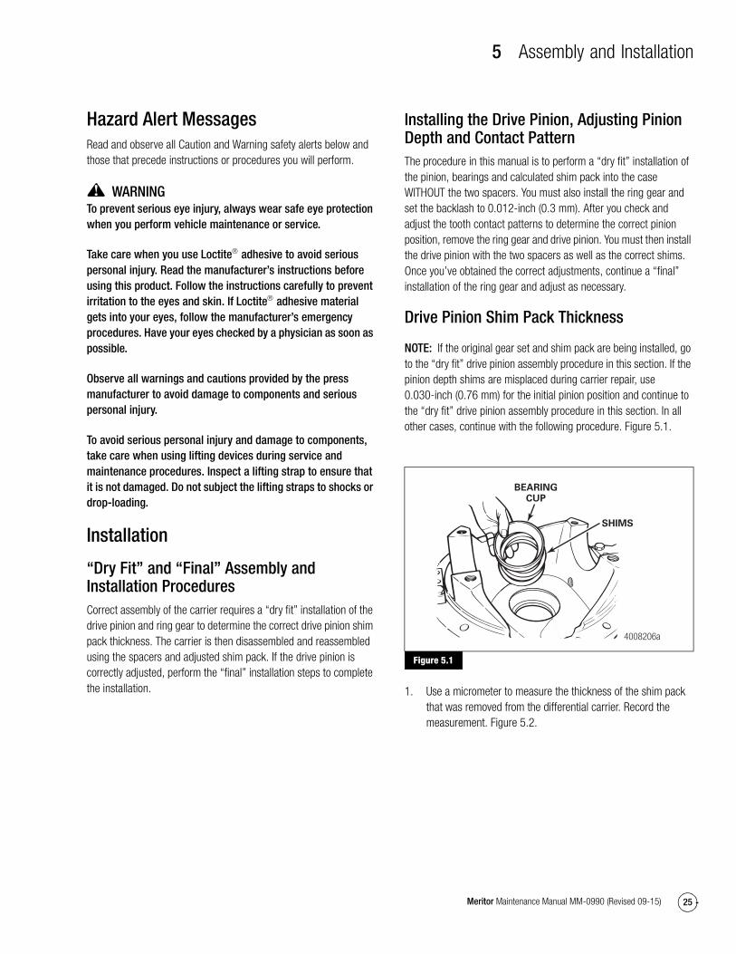
NOTE: If the original gear set and shim pack are being installed, go to the “dry fit” drive pinion assembly procedure in this section. If the pinion depth shims are misplaced during carrier repair, use 0.030-inch (0.76 mm) for the initial pinion position and continue to the “dry fit” drive pinion assembly procedure in this section. In all other cases, continue with the following procedure. Figure 5.1.
Figure 5.1
1. Use a micrometer to measure the thickness of the shim pack that was removed from the differential carrier. Record the measurement. Figure 5.2.
Figure 5.1
SHIMS
BEARINGCUP
4008206a

5 Assembly and Installation
26 Meritor Maintenance Manual MM-0990 (Revised 09-15)
Figure 5.2
2. Find the pinion cone (PC) variation number on the drive pinion you’ll replace. Record the number. Figure 5.3. The pinion cone number can be one of the following values.
� PC +6, PC –6, +6 or –6 = 0.006-inch
� PC +.15, PC 0.15 mm, +0.15 mm or –0.15 = 0.15 mm
Figure 5.3
3. If you can’t find the PC number or it’s unreadable, install a new shim pack of the same thickness that you measured in Step 1.
4. If the old pinion cone number is a plus (+), ADD the cone number to the old shim pack thickness that was measured in Step 1.
5. If the old pinion cone number is a minus (–), SUBTRACT the cone number from the old shim pack thickness that was measured in Step 1.
6. Find the pinion cone variation number on the new drive pinion that will be installed. Record the number.
7. If the new pinion cone number is a plus (+), SUBTRACT the number from the standard shim pack thickness that was calculated in Step 4 or Step 5. Use new shims to make a shim pack to the determined thickness. Refer to Table B.
8. If the new pinion cone number is a minus (–), ADD the number to the standard shim pack thickness that was calculated in Step 4 or Step 5. Use new shims to make a shim pack to the determined thickness. Refer to Table B.
Table B:
Assembly
“Dry Fit”Assembly of the Drive Pinion to Verify Shim Pack
NOTE: For initial assembly to verify the shim pack, the spacers are not installed. For final assembly, the spacers are installed and preload must be established.
Figure 5.2
Figure 5.3
1002764a
PINION CONEVARIATIONNUMBER
1003032d
Examples Inches mm
1. Old Shim Pack Thickness
Old PC Number, PC +2
Standard Shim Pack Thickness
New PC Number, PC +5
New Shim Pack Thickness
0.030
+ 0.002
= 0.032
– 0.005
= 0.027
0.760
+ 0.050
= 0.810
– 0.120
= 0.690
2. Old Shim Pack Thickness
Old PC Number, PC –2
Standard Shim Pack Thickness
New PC Number, PC +5
New Shim Pack Thickness
0.030
– 0.002
= 0.028
– 0.005
= 0.023
0.760
– 0.050
= 0.710
– 0.120
= 0.590
3. Old Shim Pack Thickness
Old PC Number, PC +2
Standard Shim Pack Thickness
New PC Number, PC –5
New Shim Pack Thickness
0.030
+ 0.002
= 0.032
+ 0.005
= 0.037
0.760
+ 0.050
= 0.810
+ 0.120
= 0.930
4. Old Shim Pack Thickness
Old PC Number, PC –2
Standard Shim Pack Thickness
New PC Number, PC –5
New Shim Pack Thickness
0.030
– 0.002
= 0.028
+ 0.005
= 0.033
0.760
– 0.050
= 0.710
+ 0.120
= 0.830
5 Assembly and Installation
27Meritor Maintenance Manual MM-0990 (Revised 09-15)
1. If you are installing a new ring gear and drive pinion, the correct thickness of the shim pack between the pinion inner bearing cup and the carrier must be determined. Refer to the procedure in this section before temporarily assembling and installing the drive pinion assembly according to this procedure.
If you are installing the original ring gear and drive pinion, temporarily install the drive pinion assembly.
2. If removed, use a press and a sleeve to install the inner bearing cone onto the drive pinion. Place the sleeve onto the inner race of the bearing. Apply pressure until the bottom of the cone touches the shoulder on the pinion. Figure 5.4.
Figure 5.4
3. Apply axle lubricant to the bearing cups and cones.
4. If removed, install the shim pack and the inner bearing cup of the drive pinion.
A. Place the carrier into a press so that the legs of the carrier are toward the TOP of the press.
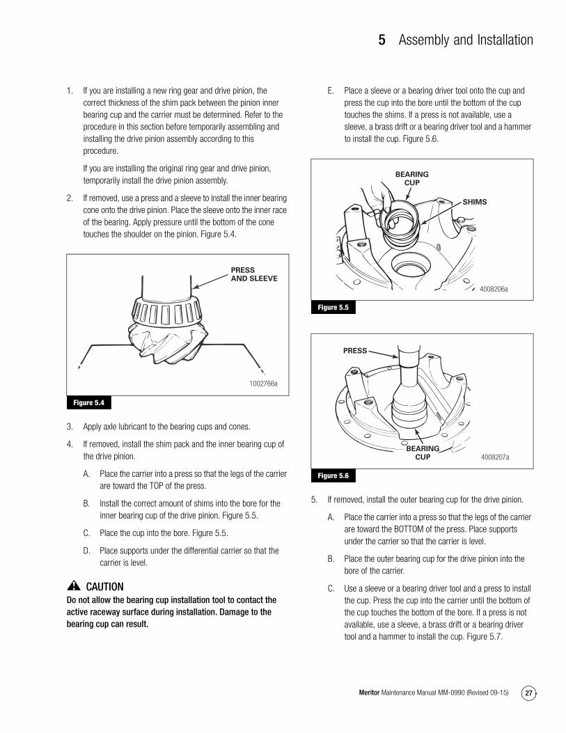
B. Install the correct amount of shims into the bore for the inner bearing cup of the drive pinion. Figure 5.5.
C. Place the cup into the bore. Figure 5.5.
D. Place supports under the differential carrier so that the carrier is level.
CAUTIONDo not allow the bearing cup installation tool to contact the active raceway surface during installation. Damage to the bearing cup can result.
E. Place a sleeve or a bearing driver tool onto the cup and press the cup into the bore until the bottom of the cup touches the shims. If a press is not available, use a sleeve, a brass drift or a bearing driver tool and a hammer to install the cup. Figure 5.6.
Figure 5.5
Figure 5.6
5. If removed, install the outer bearing cup for the drive pinion.
A. Place the carrier into a press so that the legs of the carrier are toward the BOTTOM of the press. Place supports under the carrier so that the carrier is level.
B. Place the outer bearing cup for the drive pinion into the bore of the carrier.
C. Use a sleeve or a bearing driver tool and a press to install the cup. Press the cup into the carrier until the bottom of the cup touches the bottom of the bore. If a press is not available, use a sleeve, a brass drift or a bearing driver tool and a hammer to install the cup. Figure 5.7.
Figure 5.4
1002766a
PRESSAND SLEEVE
Figure 5.5
Figure 5.6
SHIMS
BEARINGCUP
4008206a
PRESS
4008207aBEARING
CUP

5 Assembly and Installation
28 Meritor Maintenance Manual MM-0990 (Revised 09-15)
Figure 5.7
Installation
Drive Pinion1. Place the drive pinion into the carrier so that the pinion is
through the inner and the outer bearing cups.
2. Place the carrier into a press so that the legs of the carrier are toward the BOTTOM of the press. Place supports under the carrier so that the carrier is level. Place a support under the head of the drive pinion so that the inner bearing cone on the pinion shaft touches the inner bearing cup in the carrier. Figure 5.8.
Figure 5.8
3. Place the outer bearing cone onto the pinion shaft. Figure 5.9.
Figure 5.9
CAUTIONDo not use excessive press load when you install the outer pinion cone during the “dry fit” assembly procedure. Damage to the bearings can result.
4. Use a press and a sleeve to install the outer bearing cone onto the pinion. Apply no more than two tons (1814 kg) of force to verify that the bearing cone is correctly installed. Figure 5.10.
Figure 5.10
CAUTIONDo not use excessive pinion nut torque during the “dry fit” assembly procedure. Damage to the bearings can result.
5. Install the drive pinion nut to contact the bearings while allowing free movement of the pinion.
Figure 5.7
Figure 5.8
4008208a
PRESS
4000172b
BLOCK OFWOODSUPPORTINGPINION
Figure 5.9
Figure 5.10
4000173b
4000174b
SLEEVE
5 Assembly and Installation
29Meritor Maintenance Manual MM-0990 (Revised 09-15)
Assembly
Main Differential and Ring Gear
CAUTIONHeat the ring gear before seating it onto the differential case. Do not press a cold ring gear on the flange case half. A cold ring gear will damage the case half because of the tight fit.
1. Expand the ring gear by heating the gear in a tank of water to 160-180°F (71-82°C) for 10 to 15 minutes.
WARNINGWear safe clothing and gloves for protection from injury when working with the hot ring gear.
2. Use a lifting tool to safely lift the ring gear from the tank of water.
3. Install the ring gear onto the flange case half immediately after the gear is heated.
� If the ring gear does not fit easily on the case half: Heat the gear again.
4. Align the ring gear and flange case half fastener holes. Rotate the ring gear as necessary.
5. Install the bolts, nuts and washers, if equipped, that hold the ring gear to the flange case half.
� For gear set ratios 2.47 and 2.64, install the bolts from the flange half side. Figure 5.11.
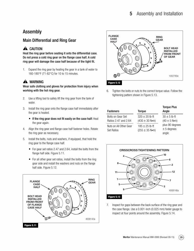
� For all other gear set ratios, install the bolts from the ring gear side and install the washers and nuts on the flange half side. Figure 5.12.
Figure 5.11
Figure 5.12
6. Tighten the bolts or nuts to the correct torque value. Follow the tightening pattern shown in Figure 5.13.
Figure 5.13
7. Inspect for gaps between the back surface of the ring gear and the case flange. Use a 0.001-inch (0.025 mm) feeler gauge to inspect at four points around the assembly. Figure 5.14.
Figure 5.11
FLANGECASEHALF
RINGGEAR
BOLT HEADINSTALLED
FROM FRONTOF FLANGECASE HALF
4008143a
Figure 5.12
Fasteners TorqueTorque Plus Angle
Bolts on Gear Set Ratios 2.47 and 2.64
320 ± 20 lb-ft (430 ± 30 N�m)
30 ± 5 lb-ft (40 ± 5 N�m) plus 90 degrees ± 5 degrees angle
Nuts on All Other Gear Set Ratios
185 ± 25 lb-ft (255 ± 35 N�m)
Figure 5.13
FLANGECASEHALF
RINGGEAR
BOLT HEADINSTALLEDFROM FRONTOF GEAR
1002780e
4008146a
10
CRISSCROSS TIGHTENING PATTERN
6
2
12
7
3
9
5
1
11
8
4
5 Assembly and Installation
30 Meritor Maintenance Manual MM-0990 (Revised 09-15)
� If the gaps exceed specification at more than three points: Inspect the flange case half and ring gear for the problem that causes the gap. Repair or replace parts as necessary. Reassemble the ring gear on the flange case half. Reinspect for gaps.
Figure 5.14
8. Use a press and the correct size sleeve to install the bearing cones onto both of the case halves. Figure 5.15.
Figure 5.15
9. Apply axle lubricant on the inside surfaces of both case halves, spider or cross, thrust washers, side gears and differential pinions.
10. Place the flange case half onto a bench with the ring gear teeth toward the TOP.
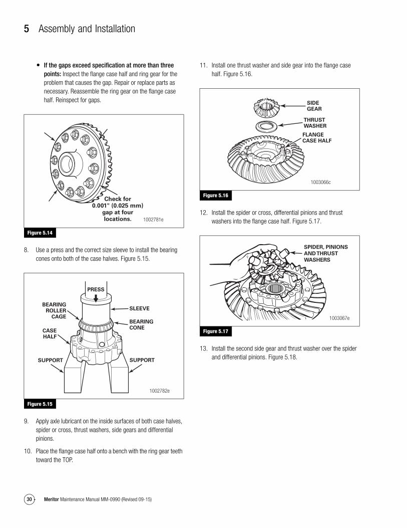
11. Install one thrust washer and side gear into the flange case half. Figure 5.16.
Figure 5.16
12. Install the spider or cross, differential pinions and thrust washers into the flange case half. Figure 5.17.
Figure 5.17
13. Install the second side gear and thrust washer over the spider and differential pinions. Figure 5.18.
Figure 5.14
Figure 5.15
Check for0.001" (0.025 mm)
gap at fourlocations. 1002781e
PRESS
SLEEVE
BEARINGCONE
SUPPORTSUPPORT
CASEHALF
BEARINGROLLER
CAGE
1002782e
Figure 5.16
Figure 5.17
SIDEGEAR
THRUSTWASHER
FLANGECASE HALF
1003066c
SPIDER, PINIONS
AND THRUST
WASHERS
1003067e

5 Assembly and Installation
31Meritor Maintenance Manual MM-0990 (Revised 09-15)
Figure 5.18
14. Place the plain half of the differential case over the flange half and gears. Rotate the plain half as needed to align the match marks. Figure 5.18 and Figure 5.19.
Figure 5.19
15. Install Dri-Loc or equivalent fasteners into the case halves using the following procedure. Refer to Section 4 for more information about Dri-Loc fasteners. If you are reinstalling used fasteners instead of new, apply Loctite 680 adhesive, Meritor specification 2297-K-5523, to the threads in the tapped holes before you install the fasteners.
A. Install the capscrews into the case halves.
B. Tighten the capscrews in a crisscross pattern to 105 ± 10 lb-ft (140 ± 15 N�m). You may also use an alternate method of tightening the capscrews in a crisscross pattern to 45 ± 5 lb-ft (60 ± 5 N�m) then further tightening them to an angle of 90 degrees ± 5 degrees. Figure 5.20. @
Figure 5.20
16. Check the rotating resistance of the differential gears. The differential assembly must rotate freely.
Check the Rotating Resistance of the Differential Assembly1. Make an inspection tool using an axle shaft that matches the
spline size of the differential side gear. Cut the shaft to approximately 12-inches (304.8 mm). Weld a nut onto the end of the shaft. Figure 5.21.
Figure 5.21
2. Place the differential and ring gear assembly flat on a work bench. Figure 5.22.
Figure 5.18
Figure 5.19
THRUSTWASHER
SIDE GEARPLAINCASEHALF
1003068c
PLAINCASEHALF
MATCHMARKS
1003069g
Figure 5.20
Figure 5.21
612
16
3
9
13
111
15
4
10
14
8
7
2
5
4008145a
CRISSCROSS TIGHTENING PATTERN
APPROXIMATELY12" (304.8 MM)
SIDEVIEW
WELD NUTTO END
OF SHAFT
ENDVIEW
1003071c

5 Assembly and Installation
32 Meritor Maintenance Manual MM-0990 (Revised 09-15)
Figure 5.22
3. Install the tool into the differential until the splines of the tool are engaged with one side gear. Figure 5.22.
4. Place a torque wrench onto the nut of the tool and rotate the differential gears. As the differential gears rotate, read the value indicated on the torque wrench. Figure 5.23.
� If the torque value exceeds 50 lb-ft (68 N�m): Disassemble the differential gears from the case halves. Inspect the case halves, spider, gears and thrust washers. Repair or replace parts. Assemble the parts and repeat Step 2 through Step 4.
Figure 5.23
Installation
“Dry Fit” Installation of the Main Differential Case and Ring Gear Assembly Into the CarrierTo carry out preliminary checks for drive pinion adjustments, perform a “dry fit” installation of the differential and ring gear assembly. Do not lubricate, apply sealant or tighten the fasteners completely. Once adjustments are made, also perform the “final” installation steps to complete the procedure.
1. If the bearing cones on the main differential case were removed, install a new cone and cup in a fully-matched set from the same manufacturer. Bearing cups and cones from different manufacturers are not interchangeable. Use a press and sleeve to install the cones onto the case. Press only on the inner race of the bearing. Figure 5.24.
Figure 5.24
2. Install the bearing cups over the bearing cones on the case halves. Figure 5.25.
Figure 5.22
Figure 5.23
TOOL FORCHECKINGRESISTANCE
1003072i
Read torque value.
1003073e
Figure 5.24
PRESS
SLEEVEBEARINGCONE
1002786g

5 Assembly and Installation
33Meritor Maintenance Manual MM-0990 (Revised 09-15)
Figure 5.25
3. Use a lifting device to safely lift the differential and ring gear assembly and install it into the carrier. The bearing cups must be flat against the bores between the carrier legs. Figure 5.25.
4. Install the bearing adjusting rings between the carrier legs. Figure 5.26.
Figure 5.26
CAUTIONCorrectly install the bearing caps into their original locations on the carrier. Do not force the bearing caps into position, which can damage the carrier. If the bearing caps are not installed correctly, the bores and threads in the cap will not match the carrier. Damage to the adjusting rings by cross-threading can result.
5. Install the bearing caps over the bearings and adjusting rings in the correct location as marked before removal. Figure 5.27.
Figure 5.27
WARNINGUse a brass or synthetic mallet for assembly and disassembly procedures. Do not hit steel parts with a steel hammer. Pieces of a part can break off. Serious personal injury and damage to components can result.
CAUTIONCorrectly install the bearing caps into their original locations on the carrier. Do not force the bearing caps into position, which can damage the carrier. If the bearing caps are not installed correctly, the bores and threads in the cap will not match the carrier. Damage to the adjusting rings by cross-threading can result.
6. Use a light leather plastic or rubber mallet to seat each bearing cap. The caps must fit easily against the bearings, adjusting rings and carrier. Do not force the bearing caps into position.
� If the bearing caps do not correctly fit into position: Check the alignment of the match marks between the caps and carrier. Remove the caps and repeat Step 4 through Step 6.
7. Hand-tighten the adjusting rings against the bearing cups to position the ring gear to the pinion with 0.012-inch (0.3 mm) backlash.
8. Install the capscrews and washers that secure the bearing caps to the carrier. Tighten the capscrews to 25 lb-ft (34 N�m). @
Do not install the capscrews and lock plates that secure the bearing adjusting rings in position. After the ring gear is installed, you must adjust the backlash of the ring gear, inspect the tooth contact patterns, then adjust the preload of the differential bearings before the lock plates and capscrews should be installed.
Figure 5.25
Figure 5.26
BEARINGCUP
BEARINGCUP
LEGBORE
1002788e
ADJUSTINGRING
LEG
1002789f
Figure 5.27
MATCHMARKS
BEARINGCAP
1002790e
5 Assembly and Installation
34 Meritor Maintenance Manual MM-0990 (Revised 09-15)
Adjustment of Pinion Shim Pack and Backlash for Contact Pattern
Ring Gear Backlash
Table C: Specifications
After checking the tooth contact patterns for top to root position, the backlash can be readjusted within the specification limits for toe to heel position, if needed. To change the location of the pattern, use the following procedures.
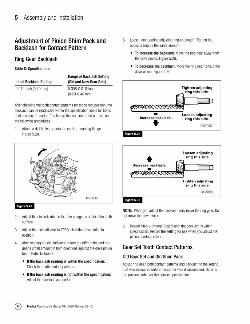
1. Attach a dial indicator onto the carrier mounting flange. Figure 5.28.
Figure 5.28
2. Adjust the dial indicator so that the plunger is against the tooth surface.
3. Adjust the dial indicator to ZERO. Hold the drive pinion in position.
4. After reading the dial indicator, rotate the differential and ring gear a small amount in both directions against the drive pinion teeth. Refer to Table C.
� If the backlash reading is within the specification: Check the tooth contact patterns.
� If the backlash reading is not within the specification: Adjust the backlash as needed.
5. Loosen one bearing adjusting ring one notch. Tighten the opposite ring by the same amount.
� To increase the backlash: Move the ring gear away from the drive pinion. Figure 5.29.
� To decrease the backlash: Move the ring gear toward the drive pinion. Figure 5.30.
Figure 5.29
Figure 5.30
NOTE: When you adjust the backlash, only move the ring gear. Do not move the drive pinion.
6. Repeat Step 2 through Step 5 until the backlash is within specification. Record the setting for use when you adjust the pinion bearing preload.
Gear Set Tooth Contact Patterns
Old Gear Set and Old Shim Pack
Adjust ring gear tooth contact patterns and backlash to the setting that was measured before the carrier was disassembled. Refer to the previous table for the correct specification.
Initial Backlash SettingRange of Backlash Setting (Old and New Gear Sets)
0.012-inch (0.30 mm) 0.008-0.018-inch (0.20-0.46 mm)
Figure 5.28
1003086e
Figure 5.29
Figure 5.30
Increase backlash.
Tighten adjustingring this side.
Loosen adjustingring this side.
1002795b
Decrease backlash.
Loosen adjustingring this side.
Tighten adjustingring this side.
1002796b

5 Assembly and Installation
35Meritor Maintenance Manual MM-0990 (Revised 09-15)
New Gear Set and/or New Shim Pack
Adjust ring gear tooth contact patterns and backlash to the correct specification from Table C.
In the following procedures, movement of the contact pattern in the length of the tooth is indicated as TOWARD the “heel” or “toe” of the ring gear. Figure 5.31.
Figure 5.31
The drive side of an amboid is the concave side of the ring gear, unlike a conventional hypoid gear. The drive side always takes precedence over the coast side; but the coast side should be evaluated as well. Figure 5.33.
Check Gear Set Tooth Contact Patterns
1. Apply a marking compound, Multan Gear Mark™ 39SY201 or equivalent, onto approximately 12 gear teeth of the ring gear. Rotate the ring gear so that the 12 gear teeth are next to the drive pinion. Figure 5.32.
Figure 5.32
2. Rotate the ring gear FORWARD and BACKWARD so that the 12 gear teeth go past the drive pinion six times to get the contact patterns. Repeat if needed to get a more clear pattern.
3. Look at the contact patterns on the ring gear teeth. Compare the patterns to Figure 5.33, Figure 5.34, Figure 5.35, Figure 5.36, Figure 5.37, Figure 5.38, Figure 5.39 and Figure 5.40.
The toe-to-heel position of the contact pattern on a good hand-rolled gear set is toe-center to center on the convex side and center to center-heel on the concave side. Figure 5.33 and Figure 5.34.
NOTE: When the carrier is in operation under load, a good contact pattern will extend approximately the full length of the gear tooth. The top of the pattern will be near the top of the gear tooth. Figure 5.41 and Figure 5.42.
The location of a good hand-rolled contact pattern for a used gear set will generally follow the new criteria, although the pattern may be narrower or the center may not be filled in.
A high-contact pattern indicates that the drive pinion was not installed deep enough into the carrier. A low-contact pattern indicates that the drive pinion was installed too deep in the carrier.
� If the contact patterns require adjustment: Continue by following Step 4 to move the contact patterns between the top and root of the gear teeth.
� If the contact patterns are centered top to root of the gear teeth: Proceed to Step 5.
Figure 5.33
Figure 5.31
Figure 5.32
4008211aHEEL
TOE
1003092d
Figure 5.33
4008131a
GOOD HAND-ROLLEDPATTERN
CONCAVE
TOP
ROOT

5 Assembly and Installation
36 Meritor Maintenance Manual MM-0990 (Revised 09-15)
Figure 5.34
Figure 5.35
Figure 5.36
Figure 5.37
Figure 5.38
Figure 5.39
Figure 5.34
Figure 5.35
Figure 5.36
4008132a
GOOD HAND-ROLLEDPATTERN
CONVEX
4008133a
HIGH PATTERN (BAD)
CONCAVE
4008134a
HIGH PATTERN (BAD)
CONVEX
Figure 5.37
Figure 5.38
Figure 5.39
4008135a
LOW PATTERN (BAD)
CONCAVE
4008136a
LOW PATTERN (BAD)
CONVEX
4008137a
SHORT AND EXTREMETOE PATTERN (BAD)
CONCAVE

5 Assembly and Installation
37Meritor Maintenance Manual MM-0990 (Revised 09-15)
Figure 5.40
Figure 5.41
Figure 5.42
4. Change the thickness of the shim pack under the inner pinion bearing cup to move the contact patterns between the top and root of the gear teeth. Use the following procedure.
NOTE: If the shim pack is changed, the bearing preload must be rechecked.
A. Remove the drive pinion, inner bearing cup and shims from the carrier. Refer to Section 3.
� To correct a high-contact pattern: Increase the thickness of the shim pack under the inner bearing cup, which moves the drive pinion TOWARD the ring gear. Figure 5.34 and Figure 5.43.
� To correct a low-contact pattern: Decrease the thickness of shim pack under the inner bearing cup, which moves the drive pinion AWAY from the ring gear. Figure 5.44.
B. Install the drive pinion, inner bearing cup and shims into the carrier. The pinion cone number can be either 100ths of a millimeter or 1,000ths of an inch.
C. Repeat Step 1 through Step 4 until the contact patterns are in the center between the top and bottom of the gear teeth.
Figure 5.43
Figure 5.44
5. Adjust ring gear backlash within the correct specification to move the contact patterns to the correct location in the length of the gear teeth. Refer to Ring Gear Tooth Contact Pattern, Backlash in this section.
A. Decrease the backlash to move the convex pattern toward the toe and concave pattern toward the heel. Figure 5.45.
Figure 5.40
Figure 5.41
Figure 5.42
4008138a
SHORT AND EXTREMEHEEL PATTERN (BAD)
CONCAVE
1001095d
SATISFACTORY PATTERN IN OPERATION
4008139a
SATISFACTORY PATTERN IN OPERATION
CONVEX
Figure 5.43
Figure 5.44
1003102fIncrease shim pack.
1003101fDecrease shim pack.

5 Assembly and Installation
38 Meritor Maintenance Manual MM-0990 (Revised 09-15)
B. Increase the backlash to move the convex pattern toward the heel and the concave pattern toward the toe. Figure 5.46.
C. Repeat Step 1 through Step 3 and Step 5 until the contact patterns are at the correct location in the length of the gear teeth.
Figure 5.45
Figure 5.46
6. If the backlash and contact patterns are correct, remove the leg cap capscrews. Use an appropriate lifting device to remove the ring gear.
Installation
“Final” Installation of the Drive Pinion and Bearing Preload AdjustmentUse the shim pack and backlash established by the “dry fit” procedure for final assembly.
The preload of the bearings on the drive pinion is controlled by a variable spacer behind the outer bearing cone.
Adjust the preload by changing the size of the spacer.
� To decrease the preload: Use a thicker spacer.
� To increase the preload: Use a thinner spacer.
If the depth of the drive pinion is changed, the thickness of the spacer must also be changed the same amount. Refer to the following examples.
� If a 0.003-inch (0.076 mm) shim is ADDED to the shim pack to INCREASE the depth of the drive pinion: A 0.003-inch (0.076 mm) larger spacer must be installed to keep the preload on the bearings.
� If a 0.003-inch (0.076-mm) shim is REMOVED from the shim pack to DECREASE the depth of the drive pinion: A 0.003-inch (0.076 mm) smaller spacer must be installed to keep the preload on the bearings.
Install the Drive Pinion
1. Apply axle lubricant to the pinion bearing cups and cones.
2. Place the carrier into a press. Figure 5.47.
Figure 5.47
3. Install the pinion shaft assembly into the carrier. Seat the inner bearing cone fully against the inner bearing cup. Figure 5.47.
4. Support the pinion shaft with blocks of wood so that the inner bearing cone remains in contact with the inner bearing cup. Figure 5.47.
5. Install the fixed spacer onto the pinion stem.
6. Install the variable spacer onto the pinion stem. If the depth of the drive pinion has increased or decreased, select a variable spacer with the same change in thickness. Figure 5.48.
Figure 5.45
Figure 5.46
Decreasebacklash.
Move pattern towardtoe, loosen adjusting
ring this side.
Tighten adjustingring this side. 1002804b
Increase.backlash.
Move pattern towardtoe, tighten adjusting
ring this side.
Loosen adjustingring this side.
1002805b
Figure 5.47
4000172b
BLOCK OFWOODSUPPORTINGPINION

5 Assembly and Installation
39Meritor Maintenance Manual MM-0990 (Revised 09-15)
Figure 5.48
7. Install the outer bearing cone onto the pinion stem. Figure 5.49.
Figure 5.49
8. Using a sleeve that is the same size as the bearing cone, press the bearing onto the pinion shaft until it is fully seated in the carrier. Figure 5.50.
Figure 5.50
Check Pinion Bearing Preload
Table D: Specifications
CAUTIONDo not install tight-fitting yokes or flanges on the shafts using a hammer or mallet. A hammer or mallet will damage the yoke or flange.
1. For the purpose of gauging preload, install a test yoke or flange that fits loosely on the shaft. Do not install the intended service yoke or flange for this procedure. Align the splines of the test yoke or flange with the shaft splines. Slide the yoke or flange over the shaft splines until seated.
2. Install the nut onto the drive pinion.
3. Fasten a yoke or flange bar to the input yoke or flange. The bar will hold the drive pinion in position when the nut is tightened.
4. Tighten the nut onto the drive pinion to the correct torque value. Refer to Table K in Section 7.
5. Remove the yoke or flange bar.
6. Attach a torque wrench onto the drive pinion nut. Rotate the drive pinion and read the value indicated on the torque wrench.
7. If the preload or torque of the pinion bearings is not within 10-50 lb-in (1.1-5.6 N�m), remove the drive pinion assembly from the carrier. Replace the variable spacer to increase or decrease preload. Refer to the procedure in this section. Repeat Steps 1 through Step 6 to recheck preload.
Figure 5.48
Figure 5.49
4005396b
SPACERS
SHIMLOCATIONS
CUP-TYPE DESIGN,AMBOID REAR
4000173b
Figure 5.50
New pinion bearings 10-50 lb-in (1.1-5.6 N�m)
Used pinion bearing in good condition
20-40 lb-in (2.2-4.5 N�m)
4000174b
SLEEVE

5 Assembly and Installation
40 Meritor Maintenance Manual MM-0990 (Revised 09-15)
� To increase preload: Install a thinner bearing variable spacer.
� To decrease preload: Install a thicker bearing variable spacer.
8. Once the desired preload is obtained, remove the test yoke. Install the seal and the service yoke. Refer to the procedures in this section.
Replace the Variable Spacer to Adjust Pinion Bearing Preload
NOTE: Do not grind spacers by hand. The surfaces must be parallel within 0.0001-inch (0.0020 mm). You must use the correct spacers.
If you must adjust preload, use the following procedure to replace the variable spacer with one of a different thickness.
1. Install a yoke or flange bar to prevent the drive pinion assembly from rotating. Remove the nut and the washer from the shaft of the drive pinion.
2. Press the drive pinion out of the bearing cone. Remove the outer bearing cone from the differential carrier.
3. Reinstall the drive pinion assembly using the correct size variable spacer.
4. Recheck the drive pinion bearing preload using the procedure in this section.
“Final” Installation of the Main Differential Case and Ring Gear Assembly Into the Carrier1. Rotate the carrier in the repair stand until the back surface of
the ring gear is toward the TOP.
2. Install the jam nut into the middle of the thrust screw. Figure 5.51.
Figure 5.51
3. Apply adhesive sealant, Meritor specification 2297-D-7076, 2297-H-7054 or 2297-B-5436, in a continuous 0.06-inch (1.5 mm) wide bead around the circumference of the thrust screw.
4. Install the thrust screw into the carrier until the small end of the screw is visible inside the carrier. Figure 5.52.
Figure 5.52
5. Clean and dry the bearing cups and bores of the carrier legs and bearing caps.
6. Apply axle lubricant to the bearing cones and inside surface of the bearing cups.
NOTE: Meritor specification 2297-P-3994 adhesive will dry in approximately two hours. You must complete the procedure within two hours from the time you apply the adhesive. If two hours have passed since application, clean the adhesive from the parts and apply new adhesive.
Figure 5.51
Figure 5.52
JAM NUT
4000176a
THRUSTSCREW
4008101a
THRUSTBLOCK
THRUSTSCREW
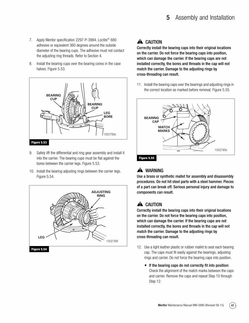
5 Assembly and Installation
41Meritor Maintenance Manual MM-0990 (Revised 09-15)
7. Apply Meritor specification 2297-P-3994, Loctite 680 adhesive or equivalent 360 degrees around the outside diameter of the bearing cups. The adhesive must not contact the adjusting ring threads. Refer to Section 4.
8. Install the bearing cups over the bearing cones in the case halves. Figure 5.53.
Figure 5.53
9. Safely lift the differential and ring gear assembly and install it into the carrier. The bearing cups must be flat against the bores between the carrier legs. Figure 5.53.
10. Install the bearing adjusting rings between the carrier legs. Figure 5.54.
Figure 5.54
CAUTIONCorrectly install the bearing caps into their original locations on the carrier. Do not force the bearing caps into position, which can damage the carrier. If the bearing caps are not installed correctly, the bores and threads in the cap will not match the carrier. Damage to the adjusting rings by cross-threading can result.
11. Install the bearing caps over the bearings and adjusting rings in the correct location as marked before removal. Figure 5.55.
Figure 5.55
WARNINGUse a brass or synthetic mallet for assembly and disassembly procedures. Do not hit steel parts with a steel hammer. Pieces of a part can break off. Serious personal injury and damage to components can result.
CAUTIONCorrectly install the bearing caps into their original locations on the carrier. Do not force the bearing caps into position, which can damage the carrier. If the bearing caps are not installed correctly, the bores and threads in the cap will not match the carrier. Damage to the adjusting rings by cross-threading can result.
12. Use a light leather plastic or rubber mallet to seat each bearing cap. The caps must fit easily against the bearings, adjusting rings and carrier. Do not force the bearing caps into position.
� If the bearing caps do not correctly fit into position: Check the alignment of the match marks between the caps and carrier. Remove the caps and repeat Step 10 through Step 12.
Figure 5.53
Figure 5.54
BEARINGCUP
BEARINGCUP
LEGBORE
1002788e
ADJUSTINGRING
LEG
1002789f
Figure 5.55
MATCHMARKS
BEARINGCAP
1002790e

5 Assembly and Installation
42 Meritor Maintenance Manual MM-0990 (Revised 09-15)
13. Hand-tighten the adjusting rings against the bearing cups to position the ring gear to the pinion with 0.012-inch (0.3 mm) backlash.
14. Install the capscrews and washers that secure the bearing caps to the carrier. Tighten the capscrews to 25 lb-ft (34 N�m). @
Do not install the capscrews and lock plates that secure the bearing adjusting rings in position. After the ring gear is installed, you must adjust the backlash of the amboid gear, inspect the tooth contact patterns, then adjust the preload of the differential bearings before the lock plates and capscrews should be installed.
Adjustment
Differential Bearings PreloadUse either the dial indicator or the large micrometer method to inspect and adjust the main differential side bearings preload.
NOTE: The lock plates and capscrews for the adjusting rings are installed after the tooth contact pattern is rechecked.
Dial Indicator Method
1. Attach a dial indicator onto the carrier mounting flange so that the plunger or the pointer is against the back surface of the ring gear. Figure 5.56.
Figure 5.56
CAUTIONWhen you turn the adjusting rings, always use a tool that engages two or more opposite notches in the ring. An adjusting ring tool can be used for this purpose. If the tool does not correctly fit into the notches, damage to the lugs will occur.
2. Use an adjusting ring tool to loosen the adjusting ring that is opposite the ring gear. A small amount of end play will show on the dial indicator. Figure 5.57.
Figure 5.57
3. Use one of the following methods to move the differential and the ring gear carefully to the left and right while you read the dial indicator.
A. Insert two pry bars between the bearing adjusting rings and the ends of the differential case. The pry bars must not touch the differential bearings. Figure 5.58.
B. Insert two pry bars between the differential case or the ring gear and the carrier at locations other than described in Step A. The pry bars must not touch the differential bearings. Figure 5.59.
Figure 5.58
Figure 5.56
DIALINDICATOR
1003078f
Figure 5.57
Figure 5.58
ADJUSTINGRING TOOL
1003079d
ADJUSTINGRINGOPPOSITERING GEAR
Bars must nottouch bearings.
1003080h
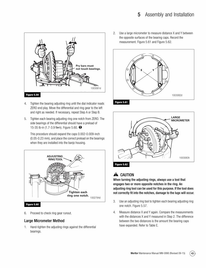
5 Assembly and Installation
43Meritor Maintenance Manual MM-0990 (Revised 09-15)
Figure 5.59
4. Tighten the bearing adjusting ring until the dial indicator reads ZERO end play. Move the differential and ring gear to the left and right as needed. If necessary, repeat Step A or Step B.
5. Tighten each bearing adjusting ring one notch from ZERO. The side bearings of the differential should have a preload of 15-35 lb-in (1.7-3.9 N�m). Figure 5.60. @
This procedure should expand the caps 0.002-0.009-inch (0.05-0.23 mm), and place the correct preload on the bearings when they are installed into the banjo housing.
Figure 5.60
6. Proceed to check ring gear runout.
Large Micrometer Method
1. Hand-tighten the adjusting rings against the differential bearings.
2. Use a large micrometer to measure distance X and Y between the opposite surfaces of the bearing caps. Record the measurement. Figure 5.61 and Figure 5.62.
Figure 5.61
Figure 5.62
CAUTIONWhen turning the adjusting rings, always use a tool that engages two or more opposite notches in the ring. An adjusting ring tool can be used for this purpose. If the tool does not correctly fit into the notches, damage to the lugs will occur.
3. Use an adjusting ring tool to tighten each bearing adjusting ring one notch. Figure 5.57.
4. Measure distance X and Y again. Compare the measurements with the distances X and Y measured in Step 2. The difference between the two distances is the amount the bearing caps have expanded. Refer to Table E.
Figure 5.59
Figure 5.60
Pry bars mustnot touch bearings.
1003081d
ADJUSTINGRING TOOL
Tighten eachring one notch.
1002794d
Figure 5.61
Figure 5.62
1003082d
1003083h
LARGEMICROMETER

5 Assembly and Installation
44 Meritor Maintenance Manual MM-0990 (Revised 09-15)
Table E: Example
5. If the difference is at or within the specification in Table F: Continue by checking the runout.
If the difference is less than the specification: Repeat as needed.
NOTE: The maximum legspread between bearing caps for the 140/145/14X series cannot exceed 13.941-inches (354.101 mm).
Table F: Expansion Between Bearing Caps
Ring Gear Runout1. Attach a dial indicator onto the carrier mounting flange.
Figure 5.63.
Figure 5.63
2. Adjust the dial indicator so that the plunger or pointer is against the back surface of the ring gear. Figure 5.63. Set the dial indicator to ZERO.
3. Rotate the differential and ring gear. Read the dial indicator. The ring gear runout must not exceed 0.008-inch (0.200 mm).
� If the ring gear runout is within the specification: Set the backlash and contact patterns to the settings determined in the “Check Gear Set Tooth Contact Patterns” procedure in this section.
� If the ring gear runout exceeds the specification: Remove the differential and ring gear assembly from the carrier. Refer to Section 3.
A. Inspect the differential parts, including the carrier, for wear and damage. Repair or replace parts as necessary.
B. Install the main differential case and ring gear assembly into the carrier. Refer to the procedure in this section.
C. Repeat the procedure for preload adjustment of the differential side bearings.
4. Once the adjustments are complete, tighten the bearing cap capscrews down to a final torque of 360 ± 40 lb-ft (485 ± 55 N�m). You may also use the alternate method of tightening the capscrews to 150 ± 35 lb-ft (200 ± 50 N�m) then to an angle of 90 degrees ± 5 degrees. @
5. Once all adjustments are complete, install the capscrews and lock plates that hold the two bearing adjusting rings in position. Use the following procedures.
A. Install the lock plate onto the bearing cap so that the tab is between the lugs of the adjusting ring. Figure 5.64.
Figure 5.64
Distances X and Y BEFORE tightening the adjusting rings
= 13.927-inches (353.75 mm)
Distances X and Y AFTER tightening the adjusting rings
= 13.932-inches (353.87 mm)
13.932-inches – 13.927-inches
= 0.005-inch difference
353.87 mm – 353.75 mm = 0.12 mm difference
Axle Series
Required Micrometer Size
Deflection
Inches Millimeters
120/125 12-13″ 0.008-0.013 0.15-0.33
140/145/14X
13-14″ 0.002-0.009 0.05-0.23
160/164 16-17″ 0.002-0.009 0.05-0.23
180/185 17-18″ 0.006-0.013 0.15-0.33
Figure 5.63
Rotate ring gear.
DIALINDICATOR
1003084g
Figure 5.64
LOCKPLATE
THREADED HOLES IN CAP
1003105f
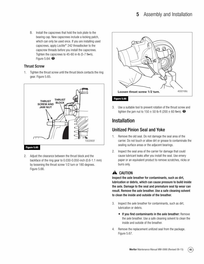
5 Assembly and Installation
45Meritor Maintenance Manual MM-0990 (Revised 09-15)
B. Install the capscrews that hold the lock plate to the bearing cap. New capscrews include a locking patch, which can only be used once. If you are installing used capscrews, apply Loctite 242 threadlocker to the capscrew threads before you install the capscrews. Tighten the capscrews to 45-60 in-lb (5-7 N�m). Figure 5.64. @
Thrust Screw
1. Tighten the thrust screw until the thrust block contacts the ring gear. Figure 5.65.
Figure 5.65
2. Adjust the clearance between the thrust block and the backface of the ring gear to 0.030-0.050-inch (0.6-1.1 mm) by loosening the thrust screw 1/2 turn or 180 degrees. Figure 5.66.
Figure 5.66
3. Use a suitable tool to prevent rotation of the thrust screw and tighten the jam nut to 150 ± 50 lb-ft (200 ± 60 N�m). @
Installation
Unitized Pinion Seal and Yoke1. Remove the old seal. Do not damage the seal area of the
carrier. Do not touch or allow dirt or grease to contaminate the sealing surface areas or the adjacent bearings.
2. Inspect the seal area of the carrier for damage that could cause lubricant leaks after you install the seal. Use emery paper or an equivalent product to remove scratches, nicks or burrs only.
CAUTIONInspect the axle breather for contaminants, such as dirt, lubrication or debris, which can cause pressure to build inside the axle. Damage to the seal and premature seal lip wear can result. Remove the axle breather. Use a safe cleaning solvent to clean the inside and outside of the breather.
3. Inspect the axle breather for contaminants, such as dirt, lubrication or debris.
� If you find contaminants in the axle breather: Remove the axle breather. Use a safe cleaning solvent to clean the inside and outside of the breather.
4. Remove the replacement unitized seal from the package. Figure 5.67.
Figure 5.65
THRUSTSCREW AND
JAM NUT
1002993f
THRUSTBLOCK
Figure 5.66
4000166cLoosen thrust screw 1/2 turn.

5 Assembly and Installation
46 Meritor Maintenance Manual MM-0990 (Revised 09-15)
Figure 5.67
CAUTIONIf a yoke is removed after it has been partially or fully installed, the unitized pinion seal will be damaged. Remove and discard the original unitized pinion seal and replace it with a new one.
If a yoke has been installed into the unitized pinion seal and then removed, the inner sleeve of the seal will be damaged. Install a new seal.
5. Place the seal, part number A1-1205Z2730, and seal driver, tool number 2730T1, in position on the carrier. Figure 5.68.
Figure 5.68
CAUTIONUse a rubber mallet to install the seal. Do not use a steel, brass or plastic hammer. Using a steel, brass or plastic hammer can damage the seal and driver tool.
6. Use a rubber mallet to drive the seal into or against the carrier. The seal must fully seat into or against the carrier. Figure 5.69.
Figure 5.69
7. Visually inspect the seal to verify that it is seated correctly.
8. Use a feeler gauge to check the seal gap. The seal is correctly installed if the gap is less than 0.010-inch (0.25 mm) around the circumference of the seal flange. If necessary, continue to drive the seal in until the correct gap is obtained.
9. Apply Meritor specification 2297-U-4519 or 0015 lubricant around the end of the yoke or flange.
10. Align the yoke or flange splines with the shaft splines. Slide the yoke or flange over the shaft splines.
CAUTIONUse a press and a sleeve or yoke/flange driver tool to install the yoke or flange. Do not use a hammer or mallet. Using a hammer or mallet can damage the bearings, yoke or flange.
11. Use a press and a sleeve or special yoke/flange driver tool, SPX Kent-Moore part number J 48718, to install the yoke or flange. Do not use the nut to draw on the yoke or flange. The yoke or flange must be seated against the outer bearing. Figure 5.70.
Figure 5.67
Figure 5.68
4005523a
4004879b
REAR-REAR INPUT
SEALDRIVER
Figure 5.69
The seal must be fully seated in or againstthe bearing cage.
SEALDRIVER
RUBBERMALLET
1003389e

5 Assembly and Installation
47Meritor Maintenance Manual MM-0990 (Revised 09-15)
Figure 5.70
12. Install the washer, if equipped, and nut onto the drive pinion.
13. Fasten a yoke or flange bar to the input yoke or flange. The bar will hold the drive pinion in position when the nut is tightened. Figure 5.71.
Figure 5.71
14. Tighten the nut onto the drive pinion to the correct torque value. Refer to Table K in Section 7.
Install the Differential Carrier into the Axle Housing
WARNINGSolvent cleaners can be flammable, poisonous and cause burns. Examples of solvent cleaners are carbon tetrachloride, and emulsion-type and petroleum-base cleaners. Read the manufacturer’s instructions before using a solvent cleaner, then carefully follow the instructions. Also follow the procedures below.
� Wear safe eye protection.
� Wear clothing that protects your skin.
� Work in a well-ventilated area.
� Do not use gasoline or solvents that contain gasoline. Gasoline can explode.
� You must use hot solution tanks or alkaline solutions correctly. Read the manufacturer’s instructions before using hot solution tanks and alkaline solutions. Then carefully follow the instructions.
When you apply some silicone gasket materials, a small amount of acid vapor is present. To prevent serious personal injury, ensure that the work area is well-ventilated. Read the manufacturer’s instructions before using a silicone gasket material, then carefully follow the instructions. If a silicone gasket material gets into your eyes, follow the manufacturer’s emergency procedures. Have your eyes checked by a physician as soon as possible.
1. Clean the inside of the axle housing and the carrier mounting surfaces. Use a cleaning solvent and rags to remove dirt. Blow dry the cleaned areas with air. Refer to Section 4.
2. Inspect the axle housing for damage. Repair or replace the axle housing. Refer to Section 4.
CAUTIONApply silicone gasket material in a continuous 0.25-inch (6 mm) bead. If you use more than this amount, gasket material can break off and plug lubrication passages. Damage to components can result.
3. Apply a continuous 0.25-inch (6 mm) bead of Loctite® Ultra Grey sealant, Meritor specification 2297-H-7054, to the mounting surface of the housing where the carrier fastens. Refer to Section 4. Figure 5.72.
Figure 5.70
Figure 5.71
4008100b
4000167c
FLANGE/YOKE
BAR

5 Assembly and Installation
48 Meritor Maintenance Manual MM-0990 (Revised 09-15)
Figure 5.72
4. Install the carrier into the axle housing. Use a hydraulic roller jack or a lifting tool.
CAUTIONDo not install the carriers using a hammer or mallet. A hammer or mallet will damage the mounting flange of the carrier and cause oil leaks.
5. Install tapered dowels at the locations shown in Figure 5.73.
Figure 5.73
6. Apply Loctite 242 threadlocker to the threads of two 1.75-inch and two 2.25-inch capscrews.
7. Install the washers and correct-size capscrews at the dowel locations shown in Figure 5.73. Tighten the capscrews in a crisscross pattern to 80-100 lb-ft (109-136 N�m). @
8. Apply Loctite 242 threadlocker to the threads of the remaining capscrews.
9. Install the remaining washers and correct-size capscrews at the locations shown in Figure 5.74. Tighten the capscrews in a crisscross pattern to 80-100 lb-ft (109-136 N�m). @
Figure 5.74
10. Tighten all the capscrews in a crisscross pattern to 210-240 lb-ft (285-325 N�m). @
11. Connect the driveline universal joint to the pinion input yoke or flange on the carrier.
Install the Axle Shafts
Straight Holes with Nuts and Hardened Washers
1. Clean the mating surfaces of the axle shaft and the wheel hub.
2. Install the gasket and axle shaft into the axle housing and carrier. The gasket and flange of the axle shafts must fit flat against the wheel hub. Figure 5.75.
� If a gasket is not available: Apply a 0.125-inch (3 mm) diameter bead of grey sealant, Meritor specification 2297-H-7054, around the mating surface of the hub and around the edge of each fastener hole. Install the axle shaft into the axle housing and carrier.
Figure 5.75
Figure 5.72
Figure 5.73
0.25" (6 MM)DIAMETER SILICONE
GASKET BEAD 4004435a
4008220a
TAPEREDDOWELS
TAPEREDDOWELS
1.75"CAPSCREW
1.75"CAPSCREW
2.75"CAPSCREW
2.75"CAPSCREW
Figure 5.74
Figure 5.75
4008220b
1.75"CAPSCREW
1.75"CAPSCREW
1.75"CAPSCREW
1.75"CAPSCREW
2.75"CAPSCREW
2.75"CAPSCREW
1002581c
TAPEREDDOWEL,
IF EQUIPPED
GASKET
STUD
SHAFTHUBAXLE
AXLESHAFT ORFLANGE
STUDNUT
WASHER

5 Assembly and Installation
49Meritor Maintenance Manual MM-0990 (Revised 09-15)
NOTE: You can also install lock washers as an alternative.
3. Install the Grade 8 nuts and hardened washers on the stud. Tighten the stud nuts to the torque specified in Table G.
Table G: Shaft-to-Hub Torque Fastener Chart
Tapered Dowel with Hardened Washer and Hardened Nut
1. Clean the mating surfaces of the axle shaft and the wheel hub.
2. Install the gasket and axle shaft into the axle housing and carrier. The gasket and flange of the axle shafts must fit flat against the wheel hub. Figure 5.75.
� If a gasket is not available: Apply a 0.125-inch (3 mm) diameter bead of grey sealant, Meritor specification 2297-H-7054, around the mating surface of the hub and around the edge of each fastener hole. Install the axle shaft into the axle housing and carrier.
3. Install solid tapered dowels over each stud and into the flange of the axle shaft. Use a punch or a drift and hammer, if necessary.
NOTE: You can also install lock washers as an alternative.
4. Install the Grade 8 nuts and hardened washers on the stud. Tighten the stud nuts to the torque specified in Table G.
Fill the Axle with Lubricant
NOTE: For additional lubrication information, refer to Maintenance Manual 1, Preventive Maintenance and Lubrication. To obtain this publication, refer to the Service Notes page on the front inside cover of this manual.
1. Park the vehicle on a level surface. When the angle of the drive pinion changes, the lubricant capacity of the axle will change.
2. Remove the fill plug from the side of the bowl cover of the axle housing. Figure 5.76.
Figure 5.76
3. Fill the axle with lubricant until the lubricant level is to the bottom of the fill plug hole. Refer to Section 6.
4. Install the fill plug. Tighten the fill plug to 35 lb-ft (47 N�m). When correctly installed, one complete thread of the fill plug is visible between the housing and plug head. @
5. Road test the vehicle in an unloaded condition for one to two miles (1.6-3.2 km) at speeds not more than 25 mph (40 kmh). Recheck the lubricant levels and all the fasteners.
FastenerThread Size
Torque Value — Grade 8 Nuts lb-ft (N�m)
Plain Nut Locknut
Stud Nut or Axle Shaft
0.62-18
0.75-16
180-230 (244-312)
310-400 (420-542)
150-190 (203-258)
270-350 (366-475)
Studs All Install the coarse thread end of the stud into the hub and tighten to the last thread.
Figure 5.76
FILLPLUG
FILL PLUG LOCATION IN BACK OF AXLE HOUSING BOWL
1002591e
TEMPERATUREINDICATOR
PLUG — DONOT REMOVE

6 Lubrication
50 Meritor Maintenance Manual MM-0990 (Revised 09-15)
6 LubricationLubrication
NOTE: For complete information on lubricating drive axles and carriers, refer to Maintenance Manual 1, Preventive Maintenance and Lubrication. To obtain this publication, refer to the Service Notes page on the front inside cover of this manual.
Refer to Table H, Table I and Table J for information on lubricants, schedules and capacities. To obtain lubricants, refer to the Service Notes page on the front inside cover of this manual.
Table H: Lubricant Cross Reference, Viscosity and Temperature Chart
Table I: Oil Change Intervals and Specifications for All Rear Drive Axles
Meritor Lubricant Specification Description Cross Reference
Minimum Outside Temperature
Maximum Outside Temperature
O-76-A Hypoid Gear Oil GL-5, S.A.E. 85W/140 10°F (–12.2°C) - - -**
O-76-B Hypoid Gear Oil GL-5, S.A.E. 80W/140 –15°F (–26.1°C) - - -**
O-76-D Hypoid Gear Oil GL-5, S.A.E. 80W/90 –15°F (–26.1°C) - - -**
O-76-E Hypoid Gear Oil GL-5, S.A.E. 75W/90 –40°F (–40°C) - - -**
O-76-J Hypoid Gear Oil GL-5, S.A.E. 75W –40°F (–40°C) 35°F (1.6°C)
O-76-L Hypoid Gear Oil GL-5, S.A.E. 75W/140 –40°F (–40°C) - - -**
**There is no upper limit on these outside temperatures, but the axle sump temperature must never exceed 250°F (121°C).
Vocation or Vehicle Operation Linehaul
Motorhome
City Delivery
Check Oil Level Every 25,000 miles (40 000 km) or the fleet maintenance interval (whichever comes first)
Every 10,000 miles (16 000 km), once a month or the fleet maintenance interval (whichever comes first)
Petroleum based oil change on axle WITH or WITHOUT pump and filter system
Every 100,000 miles (160 000 km) or annually, whichever comes first
Every 50,000 miles (80 000 km) or annually, whichever comes first
Synthetic oil change on axle WITHOUT pump and filter system*
Every 250,000 miles (400 000 km) or annually, whichever comes first
Every 100,000 miles (160 000 km) or annually, whichever comes first
Synthetic oil change on axle WITH pump and filter system*
Every 500,000 miles (800 000 km) Every 250,000 miles (400 000 km)
*This interval applies to approved semi-synthetic and full-synthetic oils only. For a list of approved extended-drain axle oils, refer to TP-9539, Approved Rear
Drive Axle Lubricants. To obtain this publication, refer to the Service Notes page on the front inside cover of this manual.

6 Lubrication
51Meritor Maintenance Manual MM-0990 (Revised 09-15)
Lubricant Capacities
Use the following lubricant capacities as a guide only. The capacities are measured with the drive pinion in the horizontal position. When the angle of the drive pinion changes, the lubricant capacity of the axle will change.
Table J: Lubricant Capacities
Axle Model
Capacity
U.S. Pints Liters
Forward Axle of Tandem
MT-40-14X 30.2 14.3
Rear Axle of Tandem
MT-40-14X 25.8 12.2

7 Specifications
52 Meritor Maintenance Manual MM-0990 (Revised 09-15)
7 SpecificationsFastenersThe torque values in Table K are for fasteners that have a light application of oil on the threads.
� If the fasteners are dry: Increase the torque values by 10%.
� If the fasteners have a heavy application of oil on the threads: Decrease the torque values by 10%.
If you do not know the size of the fastener that is being installed, measure the fastener. Use the following procedure.
American Standard Fasteners
1. Measure the diameter of the threads in inches, dimension X. Figure 7.1.
2. Count the amount of threads there are in one-inch. Figure 7.1.
3. Compare the size of the fastener measured to the list of fasteners in Table K to find the correct torque value.
Example
American Standard size fastener is 0.50-13.
� 0.50 is the diameter of the fastener in inches or dimension X.
� 13 is the amount of threads in one-inch.
Metric Fasteners
1. Measure the diameter of the threads in millimeters (mm), dimension X. Figure 7.2.
2. Measure the distance of 10 threads, point to point in millimeters (mm), dimension Y. Make a note of dimension Y. Figure 7.2.
3. Divide the dimension Y by 10. The result will be the distance between two threads or pitch.
4. Compare the size of the fastener measured to the list of fasteners in Table K to find the correct torque value.
Figure 7.1
Figure 7.2
Examples
Fastener Type How to Measure
0.50-13
Standard American size (Figure 7.1)
0.50 = the diameter of the fastener in inches, dimension X
13 = the number of threads in one-inch
M8 x 1.25
Metric (Figure 7.2)
M8 = the diameter in millimeters, dimension X
1.25 = the distance between two threads, pitch
Figure 7.1
Figure 7.2
AMOUNTOF THREADS
IN 1"
1"
X
1003113aX DIMENSION = EXAMPLE 1/2"
X
Y
1003114b
PITCH
X DIMENSION = EXAMPLE M8 OR 8 MMY DIMENSION = DISTANCE OF 10 THREADS

7 Specifications
53Meritor Maintenance Manual MM-0990 (Revised 09-15)
Figure 7.3
Figure 7.3
4008098a
7
6
10
9
8
4
5
3
2
1

7 Specifications
54 Meritor Maintenance Manual MM-0990 (Revised 09-15)
Table K: Torque Chart
Table L: Drive Pinion Bearings — Preload
Fastener Thread Size
Torque Value
lb-ft N�m
1 Yoke Nut M39 x 1.5 920-1130 (1250-1535)
2 Carrier-to-Axle Housing Capscrew
5/8″ 210-240 (285-325)
3 Thrust Screw Jam Nut M22 x 1.5 150 ± 50 (200 ± 60)
4 Adjusting Ring Lock Plate Capscrew
M6 x 1-6g Class 8.8 50 ± 10 lb-in (6 ± 1)
5 Bearing Cap Capscrews M20 x 2.5-6g Class 10.9 Initial torque: 20 ± 8 (25 ± 10)
Final torque: 360 ± 40 (485 ± 55)
Torque Plus Angle Method: 150 ± 35 (200 ± 50) plus angle tighten to 90 degrees ± 5 degrees
6 Case Half Bolts M12 x 1.75 41X-1618 Flange Head Class 12.9
105 ± 10 (140 ± 15)
Optional Method: 45 ± 5 lb-ft (60 ± 5 N�m) plus angle tighten to 90 degrees ± 5 degrees
7 Ring Gear to Flange Half Capscrews (For 2.47 and 2.64 Gear Set Ratios)
M16 x 1.5-6g Class 12.9 320 ± 20 (430 ± 30)
Optional Method: 30 ± 5 lb-ft (40 ± 5 N�m) plus angle tighten to 90 degrees ± 5 degrees
8 Ring Gear to Flange Half Nuts (For MR and FR Gear Set Ratios)
M16 x 1.5-6g Class 10.9 185 ± 25 (255 ± 35)
Optional Method: 30 ± 5 lb-ft (40 ± 5 N�m) plus angle tighten to 90 degrees ± 5 degrees
9 Drain and Fill Plugs 0.75″-14 35 Minimum (47.5 Minumum)
10 Breather 0.38″-18 25 ± 5 (30 ± 7)
Specification New bearings 10-50 lb-in (1.1-5.6 N�m)
Used bearings 20-40 lb-in (2.2-4.5 N�m)
Adjustment Preload is controlled by the thickness of the spacer between bearings.
To increase preload, install a thinner spacer.
To decrease preload, install a thicker spacer.
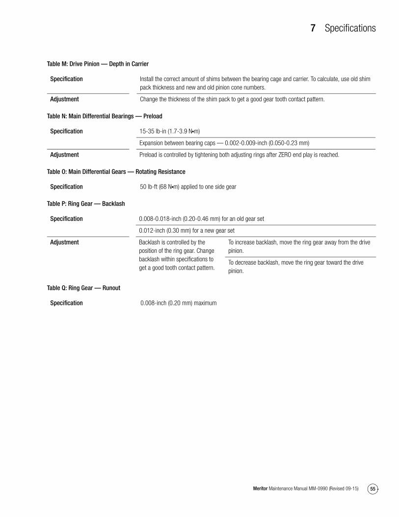
7 Specifications
55Meritor Maintenance Manual MM-0990 (Revised 09-15)
Table M: Drive Pinion — Depth in Carrier
Table N: Main Differential Bearings — Preload
Table O: Main Differential Gears — Rotating Resistance
Table P: Ring Gear — Backlash
Table Q: Ring Gear — Runout
Specification Install the correct amount of shims between the bearing cage and carrier. To calculate, use old shim pack thickness and new and old pinion cone numbers.
Adjustment Change the thickness of the shim pack to get a good gear tooth contact pattern.
Specification 15-35 lb-in (1.7-3.9 N�m)
Expansion between bearing caps — 0.002-0.009-inch (0.050-0.23 mm)
Adjustment Preload is controlled by tightening both adjusting rings after ZERO end play is reached.
Specification 50 lb-ft (68 N�m) applied to one side gear
Specification 0.008-0.018-inch (0.20-0.46 mm) for an old gear set
0.012-inch (0.30 mm) for a new gear set
Adjustment Backlash is controlled by the position of the ring gear. Change backlash within specifications to get a good tooth contact pattern.
To increase backlash, move the ring gear away from the drive pinion.
To decrease backlash, move the ring gear toward the drive pinion.
Specification 0.008-inch (0.20 mm) maximum

8 Vehicle Towing Instructions
56 Meritor Maintenance Manual MM-0990 (Revised 09-15)
8 Vehicle Towing InstructionsHazard Alert MessagesRead and observe all Warning and Caution hazard alert messages in this publication. They provide information that can help prevent serious personal injury, damage to components, or both.
WARNINGTo prevent serious eye injury, always wear safe eye protection when you perform vehicle maintenance or service.
When transporting a vehicle with the wheels of one or both drive axles on the road, it is possible to damage the axles if the wrong procedure is used before transporting begins. Meritor recommends that you use the following procedure.
Before Towing or Drive-Away
WARNINGEngage the parking brake to prevent the vehicle from moving before you begin maintenance or service procedures that require you to be under the vehicle. Serious personal injury can result.
1. Apply the vehicle parking brakes using the switch inside the cab of the vehicle.
NOTE: Remove both axle shafts from the axle(s) that will remain on the road when the vehicle is transported.
2. Remove the stud nuts and washers from the flange of the axle shafts. Figure 8.1.
CAUTIONDo not use a chisel or wedge to loosen the axle shaft and tapered dowels. Using a chisel or wedge can result in damage to the axle shaft, the gasket and seal, and the axle hub.
3. Loosen the tapered dowels, if used, in the flange of the axle shaft. Refer to Section 3 and Figure 8.1.
Figure 8.1
4. Identify each axle shaft that is removed from the axle assembly so they can be installed in the same location after transporting or repair is completed. Example: Match mark a mating axle shaft and hub.
5. Remove the tapered dowels, gasket, if used, and the axle shaft from the axle assembly. Figure 8.1.
6. Install a cover over the open end of each hub where an axle shaft was removed. This will prevent dirt from entering the bearing cavity and loss of lubricant.
NOTE: If an air supply will be used for the brake system of the transported vehicle, continue with Step 7 and Step 8, otherwise continue with Step 9.
7. Connect an auxiliary air supply to the brake system of the vehicle that is being transported. Before moving the vehicle, charge the brake system with the correct amount of air pressure to operate the brakes. Refer to the instructions supplied by the vehicle manufacturer for procedures and specifications. If an auxiliary air supply is not used, continue with Step 9.
8. When the correct amount of air pressure is in the brake system, release the parking brakes of the vehicle that is being transported. Step 9 is not required.
Figure 8.1
1002581c
TAPEREDDOWEL,
IF EQUIPPED
GASKET
STUD
SHAFTHUBAXLE
AXLESHAFT ORFLANGE
STUDNUT
WASHER

8 Vehicle Towing Instructions
57Meritor Maintenance Manual MM-0990 (Revised 09-15)
WARNINGBefore you service a spring chamber, carefully follow the manufacturer’s instructions to compress and lock the spring to completely release the brake. Verify that no air pressure remains in the service chamber before you proceed. Sudden release of compressed air can cause serious personal injury and damage to components.
9. If there are spring or parking brakes on the axle(s) that will remain on the road when the vehicle is transported, and they cannot be released by air pressure, manually compress and lock each spring so that the brakes are released. Refer to the manufacturer’s instructions.
After Towing or Drive-Away
WARNINGEngage the parking brake to prevent the vehicle from moving before you begin maintenance or service procedures that require you to be under the vehicle. Serious personal injury can result.
1. If an auxiliary air supply was used, apply the vehicle parking brakes using the switch inside the cab of the vehicle. If an auxiliary air supply was not used, begin with Step 2.
WARNINGBefore you service a spring chamber, carefully follow the manufacturer’s instructions to compress and lock the spring to completely release the brake. Verify that no air pressure remains in the service chamber before you proceed. Sudden release of compressed air can cause serious personal injury and damage to components.
2. Apply the vehicle spring or parking brakes by manually releasing each spring that was compressed before transporting started. Refer to the manufacturer’s instructions.
3. Disconnect the auxiliary air supply, if used, from the brake system of the vehicle that was transported. Connect the vehicle’s air supply to the brake system.
4. Remove the covers from the hubs.
NOTE: Continue with Step 5 through Step 7 to install all axle shafts.
5. Install the gasket, if used, and axle shaft into the axle housing and carrier in the same location it was removed from. The gasket and flange of the axle shaft must be flat against the hub. Rotate the axle shaft or the driveline as necessary to align the splines and the holes in the flange with the studs in the hub. Figure 8.1.
� If a gasket is not available: Apply a 0.125-inch (3 mm) diameter bead of grey sealant, Meritor specification 2297-H-7054, around the mating surface of the hub and around the edge of each fastener hole. Install the axle shaft into the axle housing and carrier.
6. Install the dowels, if used, over each stud and into the tapered holes of the flange.
7. Install the washers and stud nuts. Determine the size of the fasteners and tighten the nuts to the corresponding torque value shown Table R.
Table R: Shaft-to-Hub Torque Fastener Chart
8. Check the lubricant level in the axles and hubs where the axle shafts were removed. Add the correct type and amount of lubricant if necessary. For information about lubrication, refer to Maintenance Manual 1, Preventive Maintenance and Lubrication, or refer to the Lubrication Section of the Maintenance Manual for the axle model you are working with. To obtain this publication, refer to the Service Notes page on the front inside cover of this manual.
FastenerThread Size
Torque Value — Grade 8 Nuts lb-ft (N�m)
Plain Nut Locknut
Stud Nut or Axle Shaft
0.62-18
0.75-16
180-230 (244-312)
310-400 (420-542)
150-190 (203-258)
270-350 (366-475)
Studs All Install the coarse thread end of the stud into the hub and tighten to the last thread.

9 Special Tools
58 Meritor Maintenance Manual MM-0990 (Revised 09-15)
9 Special ToolsHazard Alert MessagesRead and observe all Warning and Caution hazard alert messages in this publication. They provide information that can help prevent serious personal injury, damage to components, or both.
WARNINGTo prevent serious eye injury, always wear safe eye protection when you perform vehicle maintenance or service.
Special Tools
How to Make a Yoke Bar1. Measure dimensions A and B of the yoke you are servicing.
Figure 9.1.
Figure 9.1
2. Calculate dimensions C and D of the yoke bar by adding 0.125-0.250-inch (3.175-6.35 mm) to dimensions A and B of the yoke. Figure 9.2.
Figure 9.2
WARNINGWear safe clothing and eye protection when you use welding equipment. Welding equipment can burn you and cause serious personal injury. Follow the operating instructions and safety procedures recommended by the welding equipment manufacturer.
3. To make the box section, cut and weld 1-inch x 2-inch (25.4 mm x 50.8 mm) of mild steel square stock according to dimensions C and D. Figure 9.2.
4. Cut a 4-foot x 1.25-inch (1.21 m x 31.75 mm) piece of mild steel round stock to make the yoke bar handle. Center weld this piece to the box section. Figure 9.2.
� To increase yoke bar rigidity: Weld two angle pieces onto the handle. Figure 9.2.
Figure 9.1
Figure 9.2
A
B
YOKE
1003459a
C
D
YOKEBAR
1003460a
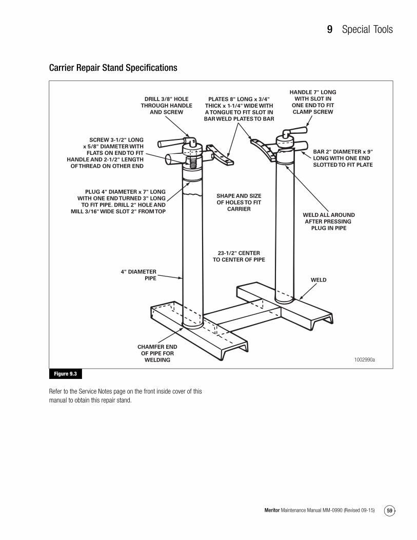
9 Special Tools
59Meritor Maintenance Manual MM-0990 (Revised 09-15)
Carrier Repair Stand Specifications
Figure 9.3
Refer to the Service Notes page on the front inside cover of this manual to obtain this repair stand.
Figure 9.3
1002990a
HANDLE 7" LONG
WITH SLOT IN
ONE END TO FIT
CLAMP SCREW
PLATES 8" LONG x 3/4"
THICK x 1-1/4" WIDE WITH
A TONGUE TO FIT SLOT IN
BAR WELD PLATES TO BAR
WELD ALL AROUND
AFTER PRESSING
PLUG IN PIPE
BAR 2" DIAMETER x 9"
LONG WITH ONE END
SLOTTED TO FIT PLATE
SHAPE AND SIZE
OF HOLES TO FIT
CARRIER
WELD
CHAMFER END
OF PIPE FOR
WELDING
23-1/2" CENTER
TO CENTER OF PIPE
PLUG 4" DIAMETER x 7" LONG
WITH ONE END TURNED 3" LONG
TO FIT PIPE. DRILL 2" HOLE AND
MILL 3/16" WIDE SLOT 2" FROM TOP
4" DIAMETER
PIPE
DRILL 3/8" HOLE
THROUGH HANDLE
AND SCREW
SCREW 3-1/2" LONG
x 5/8" DIAMETER WITH
FLATS ON END TO FIT
HANDLE AND 2-1/2" LENGTH
OF THREAD ON OTHER END

9 Special Tools
60 Meritor Maintenance Manual MM-0990 (Revised 09-15)
Multiple Lip Seals (MLS) and Seal DriversRefer to Table S for information on multiple lip seals and seal drivers. To obtain Meritor seal driver KIT 4454, refer to the Service Notes page on the front inside cover of this manual.
Table S: Multiple Lip Seals and Seal Drivers*
Forward input and output seals must be serviced with the seal and sleeve. The service part number provides both when required.
Single and Tandem Models
Axle Model and Position
Seal Service Part Number
Previous Seal Part Number Seal Drivers Sleeve Drivers
MT-40-14X Forward-Rear Unit Input (FUI)
A1-1205X2728 A-1205R2592 2728T1 2728T2
Forward-Rear Unit Output (FUO)
A1-1205Y2729 A-1205P2590 2729T1 2729T2
Rear-Rear Unit Input (RUI) A1-1205Z2730 A-1205N2588 2730T1 Not Required — Sleeve is unitized
*Forward and rear input only.

Meritor Heavy Vehicle Systems, LLC2135 West Maple Road Printed in USATroy, MI 48084 USA866-OnTrac1 (668-7221) Copyright 2015 Revised 09-15meritor.com Meritor, Inc. Maintenance Manual MM-0990 (16579)