Embed Size (px)
Citation preview

MAHARASHTRA STATE BOARD OF TECHNICAL EDUCATION
(Autonomous)
(ISO/IEC - 27001 - 2005 Certified)
SUMMER – 16 EXAMINATION
Subject Code : 17412 Model Answer
_____________________________________________________________________________
Page 1 of 26
Important Instructions to examiners:
1) The answers should be examined by key words and not as word-to-word as given in the
model answer scheme.
2) The model answer and the answer written by candidate may vary but the examiner may try
to assess the understanding level of the candidate.
3) The language errors such as grammatical, spelling errors should not be given more
Importance (Not applicable for subject English and Communication Skills.
4) While assessing figures, examiner may give credit for principal components indicated in the
figure. The figures drawn by candidate and model answer may vary. The examiner may give
credit for any equivalent figure drawn.
5) Credits may be given step wise for numerical problems. In some cases, the assumed constant
values may vary and there may be some difference in the candidate’s answers and model answer.
6) In case of some questions credit may be given by judgement on part of examiner of relevant
answer based on candidate’s understanding.
7) For programming language papers, credit may be given to any other program based on
equivalent concept
Q.1 (A) Attempt any SIX: (6×2 = 12)
(a) Enlist the types of constrained motion. Draw a label sketch of any one.
Ans.: (List – 1 mark, Sketch of any one type – 1 mark.)
Types of constrained motion:
(i) Completely constrained motion.
(ii) Incompletely constrained motion.
(iii) Successfully constrained motion.
Fig: Incompletely constrained motion

MAHARASHTRA STATE BOARD OF TECHNICAL EDUCATION
(Autonomous)
(ISO/IEC - 27001 - 2005 Certified)
SUMMER – 16 EXAMINATION
Subject Code : 17412 Model Answer
_____________________________________________________________________________
Page 2 of 26
Fig: Successfully constrained motion.
(b) Define (i) Pressure angle (ii) Pitch point related to cam.
Ans.: (1 mark for each definition)
(i) Pressure angle: It is the angle between the direction of the follower motion and a normal to
the pitch curve. This angle is very important in designing a cam profile. If the pressure angel is
too large, a reciprocating follower will jam in its bearing.
(ii) Pitch point: It is point on pitch curve having the maximum pressure angle.
(c) How are drives classified?
Ans.: (4 types – 2 marks)
Classification of drives:
(i) Belt drives.
(ii) Chain drives.
(iii) Rope.
(iv) Gear drives.
(d) Write any two disadvantages of chain drive.
Ans: (Any 2 disadvantages – 2 marks)
Disadvantages of chain drives:
1. Manufacturing cost of chains is relatively high.
2. The chain drive needs accurate mounting and careful maintenance.
3. High velocity fluctuations especially when unduly stretched.
4. Chain operations are noisy as compared to belts.
(e) Define: (i) Coefficient of fluctuation of speed.
(ii) Coefficient of fluctuation of energy.
Ans.: (1 mark for each definition)
(i) Coefficient of fluctuation of speed: Coefficient of fluctuation of speed is defined as the
ratio of the maximum fluctuation of speed to the mean speed. It is denoted by Cs.
Mathematically,
Cs = (N1 – N2) /N
Where, N1 = maximum speed in rpm; N2 =minimum speed in rpm; N = mean
speed in rpm.
MAHARASHTRA STATE BOARD OF TECHNICAL EDUCATION
(Autonomous)
(ISO/IEC - 27001 - 2005 Certified)
SUMMER – 16 EXAMINATION
Subject Code : 17412 Model Answer
_____________________________________________________________________________
Page 3 of 26
(ii) Coefficient of fluctuation of energy: Coefficient of fluctuation of energy may be
defined as the ratio of the maximum fluctuation of energy to the work done per cycle. It
is denoted by CE.
Mathematically,
CE = Maximum fluctuation of energy/ Work done per cycle.
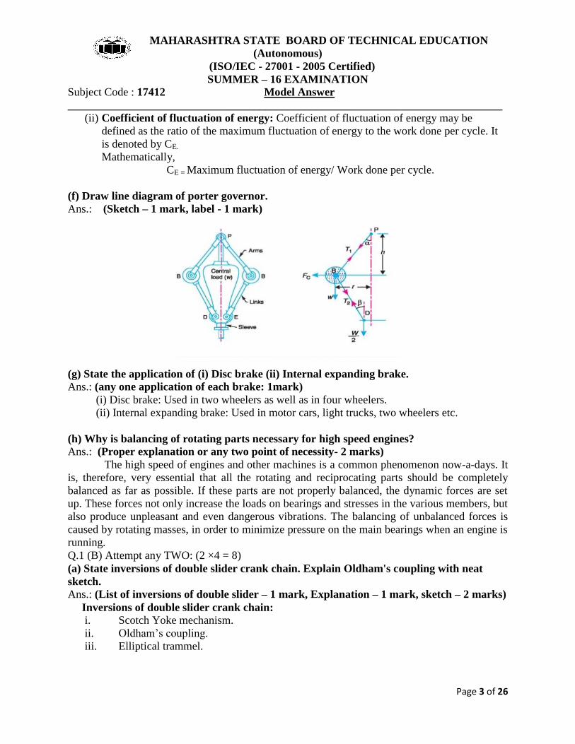
(f) Draw line diagram of porter governor.
Ans.: (Sketch – 1 mark, label - 1 mark)
(g) State the application of (i) Disc brake (ii) Internal expanding brake.
Ans.: (any one application of each brake: 1mark)
(i) Disc brake: Used in two wheelers as well as in four wheelers.
(ii) Internal expanding brake: Used in motor cars, light trucks, two wheelers etc.
(h) Why is balancing of rotating parts necessary for high speed engines?
Ans.: (Proper explanation or any two point of necessity- 2 marks)
The high speed of engines and other machines is a common phenomenon now-a-days. It
is, therefore, very essential that all the rotating and reciprocating parts should be completely
balanced as far as possible. If these parts are not properly balanced, the dynamic forces are set
up. These forces not only increase the loads on bearings and stresses in the various members, but
also produce unpleasant and even dangerous vibrations. The balancing of unbalanced forces is
caused by rotating masses, in order to minimize pressure on the main bearings when an engine is
running.
Q.1 (B) Attempt any TWO: (2 ×4 = 8)
(a) State inversions of double slider crank chain. Explain Oldham's coupling with neat
sketch.
Ans.: (List of inversions of double slider – 1 mark, Explanation – 1 mark, sketch – 2 marks)
Inversions of double slider crank chain:
i. Scotch Yoke mechanism.
ii. Oldham’s coupling.
iii. Elliptical trammel.
MAHARASHTRA STATE BOARD OF TECHNICAL EDUCATION
(Autonomous)
(ISO/IEC - 27001 - 2005 Certified)
SUMMER – 16 EXAMINATION
Subject Code : 17412 Model Answer
_____________________________________________________________________________
Page 4 of 26
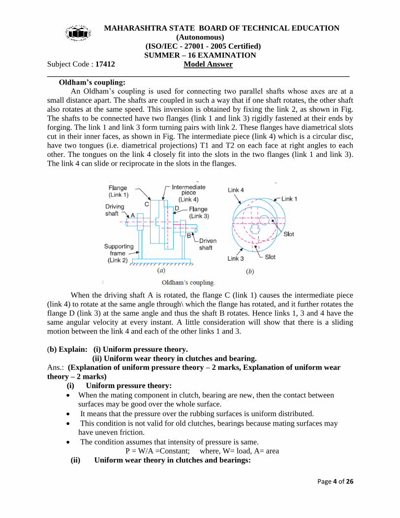
Oldham’s coupling:
An Oldham’s coupling is used for connecting two parallel shafts whose axes are at a
small distance apart. The shafts are coupled in such a way that if one shaft rotates, the other shaft
also rotates at the same speed. This inversion is obtained by fixing the link 2, as shown in Fig.
The shafts to be connected have two flanges (link 1 and link 3) rigidly fastened at their ends by
forging. The link 1 and link 3 form turning pairs with link 2. These flanges have diametrical slots
cut in their inner faces, as shown in Fig. The intermediate piece (link 4) which is a circular disc,
have two tongues (i.e. diametrical projections) T1 and T2 on each face at right angles to each
other. The tongues on the link 4 closely fit into the slots in the two flanges (link 1 and link 3).
The link 4 can slide or reciprocate in the slots in the flanges.
When the driving shaft A is rotated, the flange C (link 1) causes the intermediate piece
(link 4) to rotate at the same angle through\ which the flange has rotated, and it further rotates the
flange D (link 3) at the same angle and thus the shaft B rotates. Hence links 1, 3 and 4 have the
same angular velocity at every instant. A little consideration will show that there is a sliding
motion between the link 4 and each of the other links 1 and 3.
(b) Explain: (i) Uniform pressure theory.
(ii) Uniform wear theory in clutches and bearing.
Ans.: (Explanation of uniform pressure theory – 2 marks, Explanation of uniform wear
theory – 2 marks)
(i) Uniform pressure theory:
When the mating component in clutch, bearing are new, then the contact between
surfaces may be good over the whole surface.
It means that the pressure over the rubbing surfaces is uniform distributed.
This condition is not valid for old clutches, bearings because mating surfaces may
have uneven friction.
The condition assumes that intensity of pressure is same.
P = W/A =Constant; where, W= load, A= area
(ii) Uniform wear theory in clutches and bearings:

MAHARASHTRA STATE BOARD OF TECHNICAL EDUCATION
(Autonomous)
(ISO/IEC - 27001 - 2005 Certified)
SUMMER – 16 EXAMINATION
Subject Code : 17412 Model Answer
_____________________________________________________________________________
Page 5 of 26
When clutch, bearing become old after being used for a given period, then all
parts of the rubbing surfaces will not move with the same velocity.
The velocity of rubbing surface increases with the distance from the axis of the
rotating element.
It means that wear may be different at different radii and rate of wear depends
upon the intensity of pressure (P) and the velocity of rubbing surfaces (V).
It is assumed that the rate of wear is proportional to the product of intensity of
pressure and velocity of rubbing surfaces.
This condition assumes that rate of wear is uniform;
P*r = Constant; where, P = intensity of pressure, r = radius of rotation.
(c) Compare cross belt drive and open belt drive on the basis of:
(i) Velocity ratio. (ii) Direction of driven pulley. (iii) Length of belt drives (iv)
Application.
Ans.: (Each point – 1 mark)
Comparison between cross and open belt drive:
Sr.
No. Parameter Cross belt drive Open belt drive
01 Velocity ratio High Low
02 Direction of driven
pulley
Same as driver pulley Opposite to driven pulley
03 Length of belt drive Long Short
04
Application Large amount of
power to be
transmitted
Less amount of power to
be transmitted
Q.2 Attempt any FOUR: (4 × 4 = 16)
(a) Draw a labeled sketch of quick return mechanism of shaper and explain its working.
Ans.: (Two quick return mechanisms are used in shaper machine 1. Crank and slotted
lever quick return mechanism and Whitworth quick return mechanism. Any one
mechanism with proper explanation – 2 marks, sketch of mechanism – 2 marks. Here
crank and slotted lever quick return mechanism’s explanation is given)
Crank and slotted lever quick return motion mechanism.
This mechanism is mostly used in shaping machines, slotting machines and in rotary
internal combustion engines. In this mechanism, the link AC (i.e. link 3) forming the turning pair
is fixed, as shown in fig. The link 3 corresponds to the connecting rod of a reciprocating steam
engine. The driving crank CB revolves with uniform angular speed about the fixed centre C. A
sliding block attached to the crank pin at B slides along the slotted bar AP and thus causes AP to
oscillate about the pivoted point A. A short link PR transmits the motion from AP to the ram
which carries the tool and reciprocates along the line of stroke R1R2. The line of stroke of the
ram (i.e. R1R2) is perpendicular to AC produced.

MAHARASHTRA STATE BOARD OF TECHNICAL EDUCATION
(Autonomous)
(ISO/IEC - 27001 - 2005 Certified)
SUMMER – 16 EXAMINATION
Subject Code : 17412 Model Answer
_____________________________________________________________________________
Page 6 of 26
In the extreme positions, AP1 and AP2 are tangential to the circle and the cutting tool is
at the end of the stroke. The forward or cutting stroke occurs when the crank rotates from the
position CB1 to CB2 (or through an angle β) in the clockwise direction. The return stroke occurs
when the crank rotates from the position CB2 to CB1 (or through angle α) in the clockwise
direction. Since the crank has uniform angular speed,
(b) What are the types of kinematic pair? Give its examples.
Ans.: (Any four types with one example – 4 marks.)
Types of Kinematic Pairs. Examples
A. According to nature

MAHARASHTRA STATE BOARD OF TECHNICAL EDUCATION
(Autonomous)
(ISO/IEC - 27001 - 2005 Certified)
SUMMER – 16 EXAMINATION
Subject Code : 17412 Model Answer
_____________________________________________________________________________
Page 7 of 26
of relative motion
i. Sliding pair. Piston and cylinder, Tail stock on the lathe bed etc.
ii. Turning pair. A shaft with collars at both ends fitted into a circular
hole, Cycle wheels turning over their axles etc.
iii. Rolling pair. Ball and roller bearing.
iv. Screw pair. A lead screw of a lathe with nut, Bolt with a nut etc.
v. Spherical pair The ball and socket joint, attachment of car mirror,
pen stand etc.
B. According to nature
of contact
i. Lower Pair. All sliding pairs, turning pairs and screw pairs forms
lower pair.
ii. Higher pair A pair of friction discs, toothed gearing, belt and rope
drives, ball and roller bearings, cam and followers are
examples of higher pairs.
C. According to nature
of mechanical
arrangement
i. Closed pair or self
closed pair.
The lower pairs are self closed pairs.
ii. Open or force close
pair.
Cam and follower.
(c) Define linear velocity, angular velocity, absolute velocity and state the relation between
linear velocity and angular velocity.
Ans.: (Each point – 1 mark)
Linear Velocity: It may be defined as the rate of change of linear displacement of a body with
respect to the time. Since velocity is always expressed in a particular direction, therefore it is a
vector quantity.
Mathematically, linear velocity, v = ds/dt
Angular Velocity: It may be defined as the rate of change of angular displacement with respect
to time. It is usually expressed by a Greek letter ɷ (omega).
Mathematically, angular velocity, ɷ = dƟ /dt
Absolute Velocity: It is defined as the velocity of any point on a kinematic link with respect to
fixed point.
Relation between v and ɷ: V = r. ɷ
Where V = Linear velocity.
ɷ = angular velocity.
r = radius of rotation.

MAHARASHTRA STATE BOARD OF TECHNICAL EDUCATION
(Autonomous)
(ISO/IEC - 27001 - 2005 Certified)
SUMMER – 16 EXAMINATION
Subject Code : 17412 Model Answer
_____________________________________________________________________________
Page 8 of 26
(d) Explain the Klein's construction to determine velocity and acceleration of single slider
crank mechanism.
Ans.: (Sketch – 2 marks, Explanation of velocity triangle – 1 mark, Explanation of
acceleration diagram – 1 mark)
We have already discussed that the velocity diagram for given configuration is a triangle
OCP as shown in Fig. If this triangle is rotated through 90°, it will be a triangle oc1 p1, in which
oc1 represents VCO (i.e. velocity of C with respect to O or velocity of crank pin C) and is parallel
to OC, op1 represents VPO (i.e. velocity of P with respect to O or velocity of cross-head or piston
P) and is perpendicular to OP, and c1p1 represents VPC (i.e. velocity of P with respect to C) and
is parallel to CP. A little consideration will show that the triangles oc1p1 and OCM are similar.
Therefore,

MAHARASHTRA STATE BOARD OF TECHNICAL EDUCATION
(Autonomous)
(ISO/IEC - 27001 - 2005 Certified)
SUMMER – 16 EXAMINATION
Subject Code : 17412 Model Answer
_____________________________________________________________________________
Page 9 of 26
Thus, we see that by drawing the Klein’s velocity diagram, the velocities of various points may
be obtained without drawing a separate velocity diagram.
Klien’s acceleration diagram:
The Klien’s acceleration diagram is drawn as discussed below:
1. First of all, draw a circle with C as centre and CM as radius.
2. Draw another circle with PC as diameter. Let this circle intersect the previous circle at K and
L.
3. Join KL and produce it to intersect PO at N. Let KL intersect PC at Q. This forms the
quadrilateral CQNO, which is known as Klien’s acceleration diagram.
We have already discussed that the acceleration diagram for the given configuration is as shown
in Fig. We know that
(i) o'c' represents CO ar (i.e. radial component of the acceleration of crank pin C with respect to
O ) and is parallel to CO;
(ii) c'x represents PC ar (i.e. radial component of the acceleration of crosshead or piston P with
respect to crank pin C) and is parallel to CP or CQ;
(iii) xp' represents PC at (i.e. tangential component of the acceleration of P with respect to C )
and is parallel to QN (because QN is perpendicular to CQ); and
(iv) o'p' represents aPO (i.e. acceleration of P with respect to O or the acceleration of piston P)
and is parallel to PO or NO.
A little consideration will show that the quadrilateral o'c'x p' is similar to quadrilateral CQNO .
Therefore,
(e) Draw neat sketch of radial cam with follower and show on it:
Ans.: (Sketch and label of each given point – 4 marks)
(i) Base circle. (ii) Pitch point. (iii) Prime Circle. (iv) Cam profile.

MAHARASHTRA STATE BOARD OF TECHNICAL EDUCATION
(Autonomous)
(ISO/IEC - 27001 - 2005 Certified)
SUMMER – 16 EXAMINATION
Subject Code : 17412 Model Answer
_____________________________________________________________________________
Page 10 of 26
(f) A shaft runs at 80 rpm & drives another shaft at 150 rpm through belt drive. The
diameter of the driving pulley is 600 mm. Determine the diameter of the driven pulley in
the following cases:
(i) Taking belt thickness as 5 mm.
(ii) Assuming for belt thickness 5 mm and total slip of 4%.
Ans.: Given data;
N1 = 80 rpm.
N2 =150 rpm.
D1= 600 mm.
S = 4 %
To find; D2 =?;
(i) Case I: Taking t = 5 mm.
Velocity ratio, (V.R.) N2/N1 = (D1 + t)/ (D2 + t)…………… ……… (1 mark)
150/80 = (600 + 5)/ (D2 + 5)
Therefore, diameter of driven pulley D2 = 317.66 mm ~ 318mm……………. (1 mark)
(ii) Case II: Assuming for belt thickness 5 mm and total slip of 4%.
Velocity ratio, (V.R.) N2/N1 = {(D1 + t)/ (D2 + t)} × {1- (S/100)}…. (1 mark)
150/80 = {(600 + 5) / (D2 + 5)} × {1- (4/100)
Therefore, diameter of driven pulley D2 = 304.76 mm ~ 305 mm….. (1 mark)

MAHARASHTRA STATE BOARD OF TECHNICAL EDUCATION
(Autonomous)
(ISO/IEC - 27001 - 2005 Certified)
SUMMER – 16 EXAMINATION
Subject Code : 17412 Model Answer
_____________________________________________________________________________
Page 11 of 26
Q 3 -ATTEMPT ANY FOUR [16]
(b) Slider crank mechanism (Analytical method)
Data- Crank AB=20mm; Connecting rod BC=80mm; NBA= 1000 rpm (anticlockwise)
Crank angle = θ= 60⁰ ; n = l/r = 80/20 =4
[ 1 Mark ]
Angular velocity of crank = ωBA = 2πN/60 = π
= 104.71 rad/sec
Angular velocity of connecting rod = ωBC = ω θ
MAHARASHTRA STATE BOARD OF TECHNICAL EDUCATION
(Autonomous)
(ISO/IEC - 27001 - 2005 Certified)
SUMMER – 16 EXAMINATION
Subject Code : 17412 Model Answer
_____________________________________________________________________________
Page 12 of 26
=
=13.08 rad/sec …[ 1 Mark ]
Velocity of slider C = Vc = ω r
= 104.71 X .02[
= 2.04 m/s ………………..… [ 2 Marks]
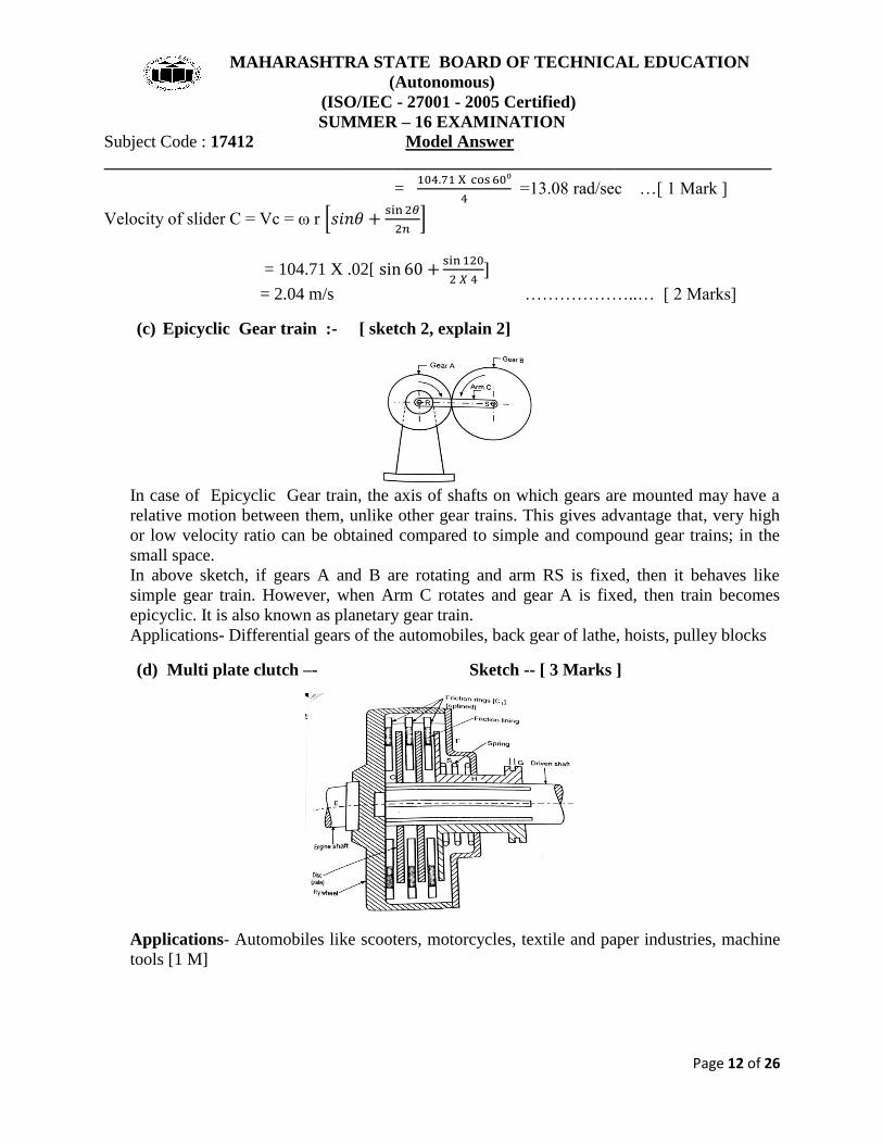
(c) Epicyclic Gear train :- [ sketch 2, explain 2]
In case of Epicyclic Gear train, the axis of shafts on which gears are mounted may have a
relative motion between them, unlike other gear trains. This gives advantage that, very high
or low velocity ratio can be obtained compared to simple and compound gear trains; in the
small space.
In above sketch, if gears A and B are rotating and arm RS is fixed, then it behaves like
simple gear train. However, when Arm C rotates and gear A is fixed, then train becomes
epicyclic. It is also known as planetary gear train.
Applications- Differential gears of the automobiles, back gear of lathe, hoists, pulley blocks
(d) Multi plate clutch –- Sketch -- [ 3 Marks ]
Applications- Automobiles like scooters, motorcycles, textile and paper industries, machine
tools [1 M]

MAHARASHTRA STATE BOARD OF TECHNICAL EDUCATION
(Autonomous)
(ISO/IEC - 27001 - 2005 Certified)
SUMMER – 16 EXAMINATION
Subject Code : 17412 Model Answer
_____________________________________________________________________________
Page 13 of 26
(e) Procedure of Balancing single rotating mass when disturbing mass in same plane
…………… [2M]
Fig. shows single rotating mass ‘m’ which is attached to a shaft rotating with angular velocity
‘ω’.
Let ‘r’ = distance of centre of gravity of ‘m’ from axis of rotation of shaft. Due to rotation of
shaft, centrifugal force ‘mrω2
‘acts
radially outwards due to inertia of mass. This force is
called disturbing force which will produce bending moment on the shaft.
A balance mass mb is introduced in the plane of rotation of disturbing mass, such that, it
neutralizes the effect of inertia force due to disturbing mass.
Thus , the inertia forces of mass ‘m’ and mass ‘mb’ must be equal and opposite.
mrω2
= mbrbω2
mr = mbrb.
Thus the balancing mass mb is used at convenient radius rb .Generally, rb is considered as
large as possible so that balance mass mb required is very small. ….[2 M]
(f) Different types of follower motions –
The follower during its travel may have one of the following motions:-
Uniform velocity, Simple harmonic motion, Uniform acceleration and retardation, Cycloidal
motion ……. [ 2 M]
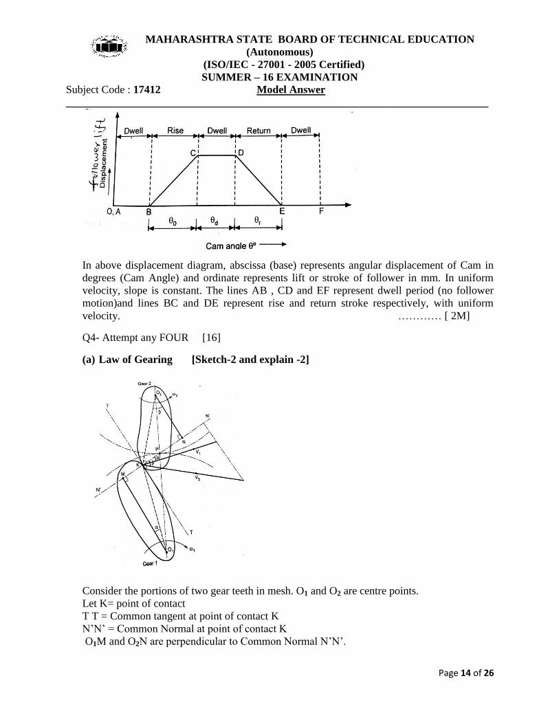
Displacement Diagram of Uniform Velocity
MAHARASHTRA STATE BOARD OF TECHNICAL EDUCATION
(Autonomous)
(ISO/IEC - 27001 - 2005 Certified)
SUMMER – 16 EXAMINATION
Subject Code : 17412 Model Answer
_____________________________________________________________________________
Page 14 of 26
In above displacement diagram, abscissa (base) represents angular displacement of Cam in
degrees (Cam Angle) and ordinate represents lift or stroke of follower in mm. In uniform
velocity, slope is constant. The lines AB , CD and EF represent dwell period (no follower
motion)and lines BC and DE represent rise and return stroke respectively, with uniform
velocity. ………… [ 2M]
Q4- Attempt any FOUR [16]
(a) Law of Gearing [Sketch-2 and explain -2]
Consider the portions of two gear teeth in mesh. O1 and O2 are centre points.
Let K= point of contact
T T = Common tangent at point of contact K
N’N’ = Common Normal at point of contact K
O1M and O2N are perpendicular to Common Normal N’N’.

MAHARASHTRA STATE BOARD OF TECHNICAL EDUCATION
(Autonomous)
(ISO/IEC - 27001 - 2005 Certified)
SUMMER – 16 EXAMINATION
Subject Code : 17412 Model Answer
_____________________________________________________________________________
Page 15 of 26
V1 and V2 =Velocities at point K w. r. t. gear 1 and 2 respectively
If mating teeth to remain in contact while transmitting motion, components of velocities must
be equal along N’N’.
So, V1cos = V2 COS
(ω1 x O1K) cos = (ω2 x O2K) cos
From triangles O1MK and O2NK putting values of cos and COS
ω1 X O1K X
=ω2 X O2K X
ω1 X O1M =ω2 X O2N
=
…………..(1)
Since O1MP and O2NP are similar triangles.
=
…………..(2)
From equations (1) and(2) , we get
=
From this, it is proved that angular velocity ratio is inversely proportional to ratio of distance
of fixed point ‘P’ ,which is pitch point. This gives constant angular velocity ratio.
In other words, the common normal at the point of contact between a pair of teeth must
always pass through the pitch point for all positions of mating gears. This is the fundamental
condition which must be satisfied while designing the profiles of teeth for gears. This is Law
of Gearing or Condition of correct gearing.
(b) Elliptical trammel-
Since Elliptical trammel consist of two turning pairs and two sliding pairs, it is inversion of
double slider crank chain.
This instrument is used for drawing ellipses. This inversion is obtained by fixing a slotted
plate (link 4) as shown in fig. It has got two right angled grooves cut into it.
1-2 is turning pair 2-3 is turning pair
1-4 is sliding pair 3-4 is sliding pair [2 M]

MAHARASHTRA STATE BOARD OF TECHNICAL EDUCATION
(Autonomous)
(ISO/IEC - 27001 - 2005 Certified)
SUMMER – 16 EXAMINATION
Subject Code : 17412 Model Answer
_____________________________________________________________________________
Page 16 of 26
As the crank BC is rotated, any point on crank except midpoint of BC and point B and C will
trace the ellipse. Midpoint of BC will trace a circle. The points B and C will move in straight
line along the slot. …….[2M]
(c) Difference between Flywheel and Governor ( Any 4 points – 4 Marks)
FLYWHEEL GOVERNOR
1.Function- To control the speed
variations caused by fluctuations of engine
turning moment during a cycle.
Function- To regulate the mean speed of
engine within prescribed limit when
there are variations of load.
2 .Mathematically it controls
2. Mathematically it controls
3. Flywheel acts as a reservoir; it stores
energy due to its mass moment of inertia
and releases energy when required during
a cycle.
3. A governor regulates the speed by
regulating the quantity of
charge/working fluid of prime mover.
4.It regulates speed in one cycle only 4. It regulates speed over a period of
time.
5.Flywheel has no control over supply of
fluid/charge
5. Governor takes care of quantity of
fluid
6. It is not an essential element of every
prime mover. It is used when there are
undesirable cyclic fluctuations.
6. It is an essential element of prime
mover since varying demand of power is
met by it.

MAHARASHTRA STATE BOARD OF TECHNICAL EDUCATION
(Autonomous)
(ISO/IEC - 27001 - 2005 Certified)
SUMMER – 16 EXAMINATION
Subject Code : 17412 Model Answer
_____________________________________________________________________________
Page 17 of 26
(d) Construction and Working of Eddy current dynamometer [2 M+ 2M]
Sketch represents working principle of this transmission type dynamometer, to measure
torque and hence power output of an engine.
It consists of rotor disc made of steel or copper. The rotor shaft is supported in
bearings and it is coupled to engine shaft.
Stator is fitted with number of electromagnets and the stator cradles in the trunion
bearings. When rotor rotates, it produces eddy currents in the stator due to magnetic
flux by passage of field current in the electromagnets.
These currents oppose the rotor motion, thus loading the engine.
The torque is measured with the help of torque arm.
This dynamometer requires some cooling arrangement since the eddy current
generate heat.
This dynamometer is compact and versatile; as it can measure high power output at
all speeds. These are used to test automobile and aircraft engines.
(e) Multiplate disc clutch
Data:- Power=P = 55 KW = 55X103 W ; N= 1800 rpm ; p = 160 KN/m
2 = 160 X 10
3 N/m
2
Internal radius R2 = 80 mm; External radius R1= =114.28 mm
Coefficient of friction
No. of plates needed to transmit torque = n = ??
Now using formula of power,
P =
55X103
=
T= 291.79 N-m ……….[ 1 Mark]
Considering uniform wear theory, for clutches, maximum pressure intensity is at minimum
radius, i.e. Rmin =R2
pmax =C / R2
160 X 103
= C/ 0.08

MAHARASHTRA STATE BOARD OF TECHNICAL EDUCATION
(Autonomous)
(ISO/IEC - 27001 - 2005 Certified)
SUMMER – 16 EXAMINATION
Subject Code : 17412 Model Answer
_____________________________________________________________________________
Page 18 of 26
C= 12800 ……….[ 1 Mark]
Axial load W = 2
= 2 X 3.142 X 12800 X(0.1142-0.08)
W =2756.96 N ……….[ 1 Mark]
Considering uniform wear theory, Torque transmitted by clutch
291.79 =
X 0.1 X 2756.96 X (0.1142+0.08) X
10.89 11
No. of plates needed is …….Ans ……….[ 1 Mark]
(f) Data-
m1= 4 kg r1= 75 mm θ1 = 45⁰ m1r1= 300 kg-mm
m2= 3kg r2= 85 mm θ2 = 135⁰ m2r2 = 265 kg-mm
m3= 2.5 kg r3= 50 mm θ3 = 240⁰ m3r3 = 125 kg-mm
Radius of balance mass = r = 75 mm
Let m=Balancing mass
Resolving horizontally,
= 300cos 45⁰+265 cos 135⁰ +125 cos 240⁰ = -37.87 kg-mm [1 M]
Resolving vertically,
= 300sin 45⁰+265 sin 135⁰ +125 sin240⁰ 291.25 kg-mm [1M]
Resultant R=
=
= 293.70 kg-mm
We know that
m X r = R
m =
= 3.91 kg ……counterbalance mass [2 M]
Q5A) (velocity diagram with calculation 03+ acceleration diagram 3+ calculations 02)

MAHARASHTRA STATE BOARD OF TECHNICAL EDUCATION
(Autonomous)
(ISO/IEC - 27001 - 2005 Certified)
SUMMER – 16 EXAMINATION
Subject Code : 17412 Model Answer
_____________________________________________________________________________
Page 19 of 26
Calculations:
i) Velocity of crank AO:
rXωV AO 480X20

MAHARASHTRA STATE BOARD OF TECHNICAL EDUCATION
(Autonomous)
(ISO/IEC - 27001 - 2005 Certified)
SUMMER – 16 EXAMINATION
Subject Code : 17412 Model Answer
_____________________________________________________________________________
Page 20 of 26
9600mm/secV AO
(AB) rodconnecting ofVelocity
Scale X l(ab)VAB X3000 1.6
4800mm/secVAB
:Slider ofVelocity
Scale X l(bo)VBO X3000 3.2
9600mm/secVBO
:link Extended ofVelocity
Scale X l(be)VBE X3000 4.5
c13500mm/seVBE
Now,
Calculations for acceleration Diagram:
mm/sec192X10480
(9600)
crank oflength
)crank of(velocity f 3
22
OAc
mm/sec14.4X101600
(4800)
rod oflength
)rod of(velocity f 3
22
ABc
mm/sec88.90X102050
(13500)
crank oflength
)link Extended of(velocity f 3
22
BEc
To be find:
1. Acceleration of slider: 3
bo 1.6X40X10el(bo)XScala 23
bo mm/sec64X10a
2. The Acceleration of point E: 3
oe 3.4X40X10el(oe)XScala 23
oe mm/sec136X10a
3. Acceleration of link AB:

MAHARASHTRA STATE BOARD OF TECHNICAL EDUCATION
(Autonomous)
(ISO/IEC - 27001 - 2005 Certified)
SUMMER – 16 EXAMINATION
Subject Code : 17412 Model Answer
_____________________________________________________________________________
Page 21 of 26
3
ab 4.3X40X10el(ab)XScala 23
ab mm/sec172X10a
Q5 b.) (Displacement diagram 03 mark+ cam profile with labeling 05 marks)
i) Displacement Diagram:
ii) cam profile:

MAHARASHTRA STATE BOARD OF TECHNICAL EDUCATION
(Autonomous)
(ISO/IEC - 27001 - 2005 Certified)
SUMMER – 16 EXAMINATION
Subject Code : 17412 Model Answer
_____________________________________________________________________________
Page 22 of 26
Q5 c ) Given data,
0.48m480mmD1 0.24mR1
0.64m640mmD2 0.32mR2
3mx
Crossed belt=
l
)r(r2x)rΠ(rL
2
2121
------------------------------------1 mark
3
0.32)(0.242(3)0.32)Π(0.24L
2
7.863mmL -------------------------------------------------------------2 marks
MAHARASHTRA STATE BOARD OF TECHNICAL EDUCATION
(Autonomous)
(ISO/IEC - 27001 - 2005 Certified)
SUMMER – 16 EXAMINATION
Subject Code : 17412 Model Answer
_____________________________________________________________________________
Page 23 of 26
Now Rotation Alter(open belt)
l
)r(r2x)rΠ(rL
2
2121
------------------------------------1 mark
3
0.32)(0.242(3)0.32)Π(0.24L
2
7.76mmL -------------------------------------------------------------2 marks
Length of belt should be changed,
L=(Length of cross belt)-(length of open belt)
=7.863-7.76
L=0.103 mm -------------------------------------------------------------2 marks
Q6A) Slip of Belt:-
Ans:- When driver pulley rotates firm grip between its surface and the belt. This firm grip
between pulley and belt is because of friction and known as frictional grip. If this
frictional grip becomes insufficient to transmit the motion of pulley to belt. Then there
will be.
1) Forward motion of driver pulley without carrying belt called as slip on driving side.
2) Some forward motion of belt without carrying driven pulley this is called as slip on
driver side.
The difference between linear speed of rim of pulley and belt on the pulley is known as
slip of belt.
The velocity ratio considering slip is given by:-
a) Neglecting Thickness of Belt and Considering Slip:-
100
5 - 1
d
d -
N
N
2
1
1
2
b) Considering Thickness:-
100
5 - 1
t d
t d -
N
N
2
1
1
2
Creep of Belt:-
The belt moves from driving pulley is known as Tight side and belt moves from driving
pulley to driver pulley as slack side.

MAHARASHTRA STATE BOARD OF TECHNICAL EDUCATION
(Autonomous)
(ISO/IEC - 27001 - 2005 Certified)
SUMMER – 16 EXAMINATION
Subject Code : 17412 Model Answer
_____________________________________________________________________________
Page 24 of 26
Tension on both i.e. on tight sides and slack side is not equal 21 T T . The belt material
is elastic material which elongates more on Tight side than the slack side resulting in
unequal stretching on both sides of drive.
A certain portion of belt when passes from slack side to tight side extends and certain
portion of belt when contracts, passes from tight side to slack side because of relative
motion.
The relative motion between belt and pulley surface due to unequal stretching of two
sides of drives is known as creep.
(Slip of belt 02 marks +creep of belt 02 marks)
ii) Single cylinder 4 – stroke I. C. Engine using Turning moment Diagram.
Ans; (Sketch 02+explanation 02)
A turning moment diagram for a four stroke cycle internal combustion engine, we
know that in a four stroke cycle internal combustion engine, there is one working stroke
after a crank has turned through two revolution i.e.7200
.
Since the pressure inside the engine cylinder is less than the atmospheric pressure during
suction stroke therefore a negative loop is formed. During the compression stroke, the
work is done on gases, therefore a higher negative loop is obtained.
During the expansion or working stroke, the fuel burns and the gases expand,
therefore a positive loop is obtained. In this stroke the work done is by the gases. During
exhaust stroke, the work is done on the gases, therefore negative loop is formed. It may
be noted that effect of inertia forces on the piston is taken is account.
Q6b) A simple band brake drum:

MAHARASHTRA STATE BOARD OF TECHNICAL EDUCATION
(Autonomous)
(ISO/IEC - 27001 - 2005 Certified)
SUMMER – 16 EXAMINATION
Subject Code : 17412 Model Answer
_____________________________________________________________________________
Page 25 of 26
Sol Given:- P = 120 N
N = 200 rpm a = 100 mm = 0.1m
D = 200 mm = 0.2m l = 280 mm = 0.28m
θ = 2250= 3.92 rad = 0.25
K = 0.3m
Ans:-
e T
T
2
1 92.325.0
2
1 e T
T .6692
T
T
2
1 -----------------01 mark
u
xX T P 2 =
28.0
0.1 X T 120 2
N 336 T2 -----------------01 mark
2.669 X T T 21
2.669 X 336 T1 ; N 896.784 T1 -----------------01 mark
RT - T T 21B - 1.0336-896.784 TB
N.m 56 TB -----------------01 mark
1) K. E. of Flywheel:-
2ω I 2
12
2
60
N 2)(mk X
2
1
2
2
60
200 X X 2 )0.3 X (250 X
2
1

MAHARASHTRA STATE BOARD OF TECHNICAL EDUCATION
(Autonomous)
(ISO/IEC - 27001 - 2005 Certified)
SUMMER – 16 EXAMINATION
Subject Code : 17412 Model Answer
_____________________________________________________________________________
Page 26 of 26
438.64 X 22.5 X 2
1 ; K. E. = 4934.80 N. m--------------------02 mark
Let n = Number of revolution before it comes to rest
Work done = n X Π X 2 X T θ X T bb
n X X 2 X 56.07
m N. n) X (352.298 ---------1 mark
Work done = change in K. E.
352.298
4934.80 n ; 14.007n --------------------1 mark
Q6c) Given data, 0100 α 2
050 α
KN 18 W 23
max N/m 10 X 300 P
0.05 μ rpm 150 N
21 R 2.5 R
Ans:- )R - (R Π X P W 3
2
2
1 ------------------------1 mark
2
2
2
2
33 )(R - )((2.5R (3.142) 10 X 300 10 X 18 2
2R 1.5 0.019
m 0.11 R2 ------------------1 mark
0.11 X 2.5 R1 ; 0.281m R1 ------------------1 mark
αsin RR
RRμW
3
2 T
2
2
2
1
3
2
3
1
------------------2 marks
022
333
50sin )11.0((0.281)
)11.0((0.281)10 X 18 X 05.0
3
2 T
22 (0.11)(0.281)
16.336 T
m N. 244.33 T ------------------1 mark
60
T N Π 2 P
60
244.33 X 150 X X 2
Watt10 X 3.837 3 K Watt 3.837
Power Lost = 3.837 KW------------------2 marks