Embed Size (px)
DESCRIPTION
DC machinery
Citation preview

define magnetic field.discuss the characteristics of a magnet.define terms associated with magnetism.discuss the three classifications of magnetic materials.discuss the difference between a magnetic circuit and electric circuit.solve problems in magnetic circuits.
LEARNING OUTCOMESAfter completing this unit, you are expected to:
Unit 1MAGNETISM and ELECTROMAGNETISM

1.1 Magnetic Field
Detecting the Presence of a Magnetic FieldMagnetism. It is defined as the property which certain materials have that permits them to produce or conduct magnetic lines of force.Magnetic Field. Is the region in which a magnetic material is acted upon by a magnetic force.Magnet. It is an object which a magnetic field exists and is either natural or man-made. The latter type can either be temporary or permanent.Magnetic force. It is the force exerted by one magnet on another to attract it or repel it.Magnetic Line of Force. A magnetic line of force represents the path along which a theoretical isolated magnetic pole would move from one pole of a magnet to the other.

Diagram of a Magnetic Field Around a Bar Magnet1.2 Characteristics of Magnetic Field Magnetic lines of force form a complete loops. Magnetic lines of force represent a tension along their length which tends to make as short as possible. Magnetic lines of force repel one another. Magnetic line of force cannot intersect but must always for individual closed loops. Magnetic fields always tend to arrange themselves in such a manner that the maximum number of lines of force is set up. Each magnet has a magnetic field around it just on the earth does. The magnetic field is strongest at the end of the magnet. In the center of the magnet the strength is negligible. Magnetic lines of force (also called magnetic flux) have direction similar to the motion of electric charges. A magnet has a north pole and a south pole just as electric charges are either negative or positive. Like poles of magnets repel whereas unlike poles attract.
Magnetism can be induced in a magnetic material by placing it in a magnetic field. The lines of force tend to spread away from each other by placing it in a magnetic field.1.3 Classifications of Magnetic Material

In accordance with the value of relative permeability the magnetic materials may be classified in the following three ways:1. Ferromagnetic materials. The relative permeabilities of these materials are much greater than unity and are dependent on the field strengths.Examples: iron, cobalt, and nickel.2. Paramagnetic materials. These have relative permeability slightly greater than unity and are magnetized slightly.Examples: aluminum, platinum, and oxygen.3. Diamagnetic materials. The relative permeability of these materials is slightly less than unity. They repel the lines of force slightly.Examples: bismuth, silver, copper, and hydrogen.
1.4 Electromagnetism
(a)
(a) (b)(c)(d)(e)(f)(a) (b)

(b)When No Current, Compass Needles All Indicate Earth’s Magnetic Field, (b) When Current Flows, Compass Needles Indicate Circular Magnetic Lines of Force around the Conductor.
Right-Hand Rule for Determining Direction of Magnetic Lines of Force around a Straight Current-Carrying Conductor.
Concentrating the Magnetic Field by Forming the Conductor into a Loop.

Magnetic Field Pattern of a Current-Carrying Solenoid.
Right-Hand Rule for Determining Direction of Magnetic Lines of Force through a Current –Carrying Solenoid.
Magnetic Field around Parallel Current-Carrying Conductors1.5 Magnetic FluxMagnetic flux is the total number of lines of force in a magnetic field. Magnetic flux and magnetic lines of force are synonymous.The letter symbol for magnetic flux is the Greek letter (phi).Magnetic flux in a magnetic circuit is the counterpart of electric current in an electric circuit.

Faraday’s Demonstration of Electromagnetic Induction.The weber is the SI unit of magnetic flux.If the flux linking a angle-turn coil builds up from zero at a rate at which will induce an average of one volt in the coil, at the end of one second the flux linking the coil will have a magnitude of one weber.The unit symbol for weber is Wb.
1.6 Magnetomotive ForceJust an electric current cannot flow in an electric circuit until we connect it to a voltage source, magnetic flux (magnetic line of force) cannot be established until a magnetomotive force is produced.
Magnetomotive force in a magnetic circuit is the counterpart of electromotive force in an electric circuit.The ampere-turn is the SI unit of magnetomotive force.The letter symbol for magnetomotive force is I.

I=¿
where I is the magnetomotive force in ampere-turns, N is the number of turns of in the coil, and I is the actual current through the coil in amperes.Example 1.1 Determine the magnetomotive force in a 50-turn coil that is carrying a 2-A electric current.Given: N= 50 turns I = 2 ARequired: IKnown: I=¿Solution: I=(50 turns ) (2 A )
I=100ampere−turns
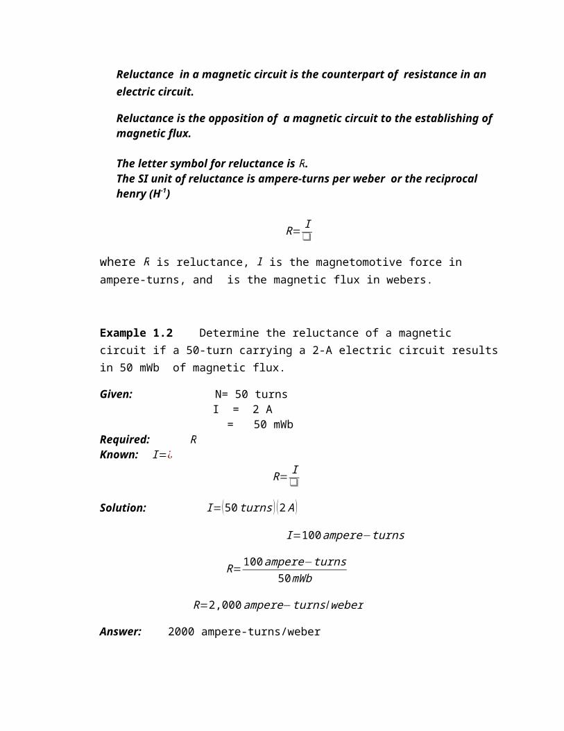
Answer: 100 ampere-turns1.7 ReluctanceFor a given electric circuit, Ohm discovered a constant proportionality between the applied voltage and the resulting current. He termed this constant the resistance of the electric circuit. Similarly, for a given magnetic circuit (of non-ferrous materials), there is a constant proportionality between the magnetomotive force and the resulting magnetic flux. This constant is called the reluctance of the magnetic circuit.Reluctance in a magnetic circuit is the counterpart of resistance in an electric circuit.Reluctance is the opposition of a magnetic circuit to the establishing of magnetic flux.
The letter symbol for reluctance is R.The SI unit of reluctance is ampere-turns per weber or the reciprocal henry (H-1)

R= Iwhere R is reluctance, I is the magnetomotive force in ampere-turns, and is the magnetic flux in webers.
Example 1.2 Determine the reluctance of a magnetic circuit if a 50-turn carrying a 2-A electric circuit results in 50 mWb of magnetic flux.Given: N= 50 turns I = 2 A = 50 mWbRequired: RKnown: I=¿ R= ISolution: I=(50 turns ) (2 A )
I=100ampere−turns
R=100ampere−turns50mWb
R=2,000ampere−turns /weber
Answer: 2000 ampere-turns/weber1.8 Magnetic Circuit
flux=magnetomotive force (mmf )
reluctance
¿ IR
R= ICGS MKS = flux in maxwells
mmf (I) = 0.4NI gilbertsN = no. of turnsI = current in amperesR = reluctance in gilberts/maxwells
R= lµo µr Al = length of the magnetic circuit in cmA = area of the magnetic circuit in cm2
= flux in webers ; 1 Wb = 108 maxwellsmmf (I) = NI ampere-turnsN = no. of turnsI = current in amperesR = reluctance in ampere-turns/weber
R= lµo µr Al = length of the magnetic circuit in mA = area of the magnetic circuit in m2
1.9 Comparison Between Magnetic and Electric Circuits.Magnetic Circuit Electric Circuit

1.Flux= mmfreluctance
2. mmf (ampere-turns)3. flux (webers)4. flux density B B=A Wb/m25. Reluctance6. Permeance (= 1/reluctance)7. Reluctivity8. Permeability (=1/reluctivity)9. Total mmf = R1+R2+R3 + . . .
1.Current= emfresistance
2. emf (volts)3. current I (amperes)4. Current density (A/m2)5. Resistance6. Conductance 7. Resistivity8. Conductivity9. Total emf = IR1 + IR2 + IR3 + . . . .
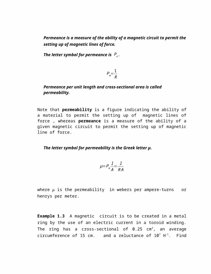
1.10 PermeabilityPermeance is a measure of the ability of a magnetic circuit to permit the setting up of magnetic lines of force.The letter symbol for permeance is Pm.
Pm=1RPermeance per unit length and cross-sectional area is called permeability.
Note that permeability is a figure indicating the ability of a material to permit the setting up of magnetic lines of force , whereas permeance is a measure of the ability of a given magnetic circuit to permit the setting up of magnetic line of force. The letter symbol for permeability is the Greek letter µ.
µ=PmlA
= lR A

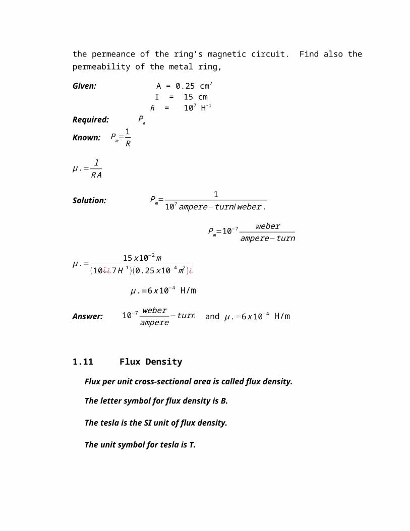
where µ is the permeability in webers per ampere-turns or henrys per meter.Example 1.3 A magnetic circuit is to be created in a metal ring by the use of an electric current in a toroid winding. The ring has a cross-sectional of 0.25 cm2, an average circumference of 15 cm. and a reluctance of 107 H-1. Find the permeance of the ring’s magnetic circuit. Find also the permeability of the metal ring,Given: A = 0.25 cm2 I = 15 cm R = 107 H-1Required: PmKnown: Pm=
1R
µ .= lR A
Solution: Pm=1
107ampere−turn /weber .
Pm=10−7 weber
ampere−turn
µ .= 15 x10−2m(10¿¿7H−1)(0.25 x10⁻⁴m2)¿
µ .=6 x10⁻⁴ H/mAnswer: 10−7 weber
ampere−turn and µ .=6 x10⁻⁴ H/m
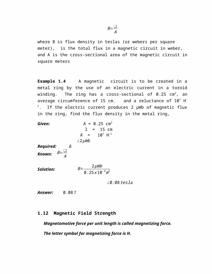
1.11 Flux DensityFlux per unit cross-sectional area is called flux density.The letter symbol for flux density is B.The tesla is the SI unit of flux density.
The unit symbol for tesla is T.B=
A
where B is flux density in teslas (or webers per square meter), is the total flux in a magnetic circuit in weber, and A is the cross-sectional area of the magnetic circuit in square metersExample 1.4 A magnetic circuit is to be created in a metal ring by the use of an electric current in a toroid winding. The ring has a cross-sectional of 0.25 cm2, an average circumference of 15 cm. and a reluctance of 107 H-1. If the electric current produces 2 µWb of magnetic flux in the ring, find the flux density in the metal ring,Given: A = 0.25 cm2 l = 15 cm R = 107 H-1 ¿2µWb Required: BKnown: B=
A
Solution: B= 2µWb
0.25 x10⁻⁴m2
¿0.08 tesla
Answer: 0.08T
1.12 Magnetic Field StrengthMagnetomotive force per unit length is called magnetizing force.The letter symbol for magnetizing force is H.From the definition of magnetizing force,
H= Il
where H is the magnetizing force in ampere-turns per meter, I is the magnetomotive force in ampere-turns, and l is the length of the magnetic circuit in meters.Since R= I
and Pm=I
Substituting equations givesµ= B
H
where µ is permeability in henrys per meter (or webers per ampere-turn for one meter cube), B is the flux density in teslas (or in webers per square meter), and H is the magnetizing force in amperes per meter (ampere-turns per meters)Note: Electrical engineering now refers magnetic field strength (intensity) as the general term for H (the magnetic counterpart of electric field strength in a dielectric)Example 1.5 For the toroidal coil described in example 1.3, find the magnetic field strength with the metal ring.Given: A = 0.25 cm2 l = 15 cm R = 107 H-1 ¿2µWb Required: HKnown: H= I
l
Solution: H=100ampere−turns
15 x 10−2m
¿666.67ampere−turns per meter
Answer: 666.67ampere−turns per meter
1.13 Magnetization CurvesAtoms of ferromagnetic materials possess unique electron orbit patterns that cause each atom to generate a tiny magnetomotive force called a magnetic moment. These atoms have the ability to rotate their magnetic axes in groups of some 1015 (more or less) adjacent atoms called magnetic domains in response to the applied magnetic field.
The extent of the magnetization, and thus the permeability of a magnetic core, depends on the flux density of the applied magnetic field. Even though we can prepare a graph as shown in Figure 1.1, showing how the permeability of a given sample of iron varies with flux density, we discover an interdependence which becomes evident when we arrange the equation µ= BH
.

B
µ
Saturation
Lower knee
Upper knee
B=µ H
Figure 1.1. Manner in Which the Permeability of Cast Steel Varies with Flux Density.For a given magnetic field strength, the flux density B depends on the permeability µ, which, in turn, depends on the flux density B. Such a situation leads to a “cut-and try” solution for flux density.To avoid this situation, we can eliminate one dependent variable by disregarding permeability and plotting an accurate graph of the manner in which the flux density in a certain type of iron varies with the magnetic field strength. Since B and H as units of measurement are both based on a cube with unit dimensions, the magnetization curve (simply BH curve) depends only on the type of iron and not on the dimensions of the magnetic circuit.
or

Figure 1.2 BH Curve for a Typical Cast-Steel Sample.
Most of the magnetization of ferromagnetic cores occurs for applied magnetizing forces (and resulting magnetic field strengths) between the lower and upper knees of the magnetization curve of Figure 1.2. In this steep region of the BH curve, the magnetic axes of the domains are switching to act as closely as possible in the same direction as the applied magnetic field. As we increase H beyond the upper knee, note that there is very little increase in flux density. This is due to almost all domains have finally aligned themselves with the applied magnetic field. We call this condition saturation of the magnetic core.
or I

Typical Magnetization Curves1.14 HysteresisAlthough the BH curve of Figure 1.2 represents the manner in which the flux density of an unmagnetized sample of iron rises as we increase the value of H, it does not represent the manner in which the flux density decreases as we decrease the magnetic field strength.

+B
-B
-H
Most magnetic materials have some retentivity. when the magnetizing force is returned to zero, the residual magnetism of the iron will produce an appreciable value of flux density. In order to get rid of this residual flux, it is necessary to pass some current through the solenoid in the opposite direction. The amount of negative magnetic field strength or magnetizing force required to demagnetize a particular sample of iron is called a coercive force.
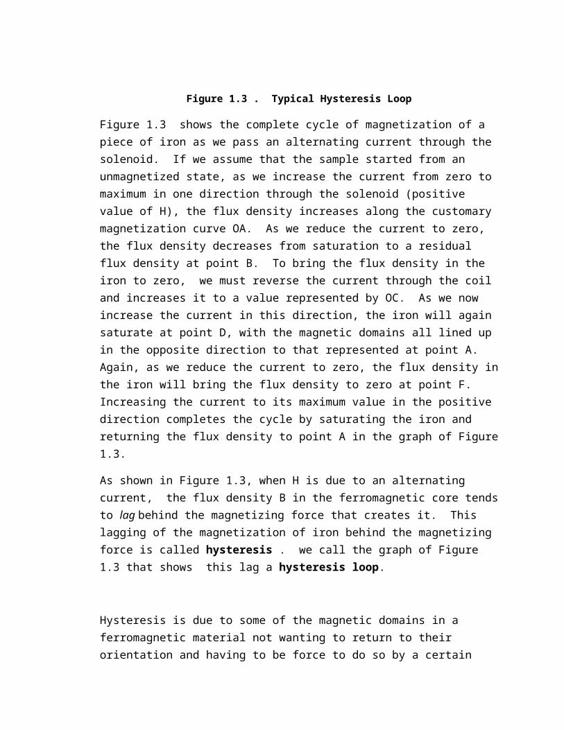
Figure 1.3 . Typical Hysteresis LoopFigure 1.3 shows the complete cycle of magnetization of a piece of iron as we pass an alternating current through the solenoid. If we assume that the sample started from an unmagnetized state, as we increase the current from zero to maximum in one direction through the solenoid (positive value of H), the flux density increases along the customary magnetization curve OA. As we reduce the current to zero,

the flux density decreases from saturation to a residual flux density at point B. To bring the flux density in the iron to zero, we must reverse the current through the coil and increases it to a value represented by OC. As we now increase the current in this direction, the iron will again saturate at point D, with the magnetic domains all lined up in the opposite direction to that represented at point A. Again, as we reduce the current to zero, the flux density in the iron will bring the flux density to zero at point F. Increasing the current to its maximum value in the positive direction completes the cycle by saturating the iron and returning the flux density to point A in the graph of Figure 1.3.As shown in Figure 1.3, when H is due to an alternating current, the flux density B in the ferromagnetic core tends to lag behind the magnetizing force that creates it. This lagging of the magnetization of iron behind the magnetizing force is called hysteresis . we call the graph of Figure 1.3 that shows this lag a hysteresis loop.Hysteresis is due to some of the magnetic domains in a ferromagnetic material not wanting to return to their orientation and having to be force to do so by a certain amount of reversed magnetizing force (coercive force). Whenever motion is accomplished against an opposing force, an energy transfer must take place. This energy is taken form the source of alternating voltage, which is responsible for the magnetic domains having to change their orientation, and is transferred to the molecules of the ferromagnetic material in the form of heat. The higher the frequency of the alternating current in the solenoid, the more rapidly the magnetic domains have to change their alignment and, therefore, the greater the hysteresis loss.The greater the retentivity of a particular type of iron. The greater the coercive force that is required to demagnetize it. This means an increased opposition by the magnetic domains to reorientation, which results in greater transfer of energy into heat. Therefore, hysteresis loss is also proportional to the retentivity of the iron. The iron selected for use in the magnetic circuits of transformers which are continually subject to an alternating mmf should have an absolute minimum retentivity if hysteresis loss is to be kept at a low value.

Consideration of Figure 1.3 will show us that the residual flux density of a sample of iron increases, the area within the hysteresis loop increases. Therefore, the area within the hysteresis loop for a given iron sample is a useful indication of its hysteresis loss.1.15 Leakage flux
Leakage Flux in a Magnetic Circuit1.16 Air GapsThe spreading apart of the magnetic lines of force as they cross an air gap is called fringing. Fringing results in the flux density in the air gap being slightly less than that in the adjacent iron sections of the magnetic circuit.If the length of the air gap is small, the fringing is small, and we can make correction for it in magnetic circuit calculations by assuming that the cross-sectional dimensions of an air gap are greater than the cross-sectional dimensions of the adjacent iron by an amount equal to the length of the air gap.

Fringing of Magnetic Lines of Force in an Air Gap.1.17 Formulas CGS SYSTEM MKS SYSTEMForce Between Poles
F=mm '
μ s2 dynes
wherem = pole strength in u.p. s = distance in cmµ = permeability
F= mm '
4 μo μr s2 N
wherem = pole strength in ampere-meter s = distance in metersµ = permeability µ = μo μr
μo = 4 x 10⁻⁷ Wb/ampere-meter μr = relative permeabilityMagnetic Field Strength
H= Fm '
oerstedwherem = pole strength in u.p. F = force in dynesµ = permeabilityH=
mm '
μ s2
m'
H= m
μ s2 oersted
H= Fm '
amp-turns/mH= m
4 μo μr s2 amp-turns/m
whereF = force in newtons s = distance in metersµ = permeability µ = μo μr
μo = 4 x 10⁻⁷ Wb/ampere-meter μr = relative permeability
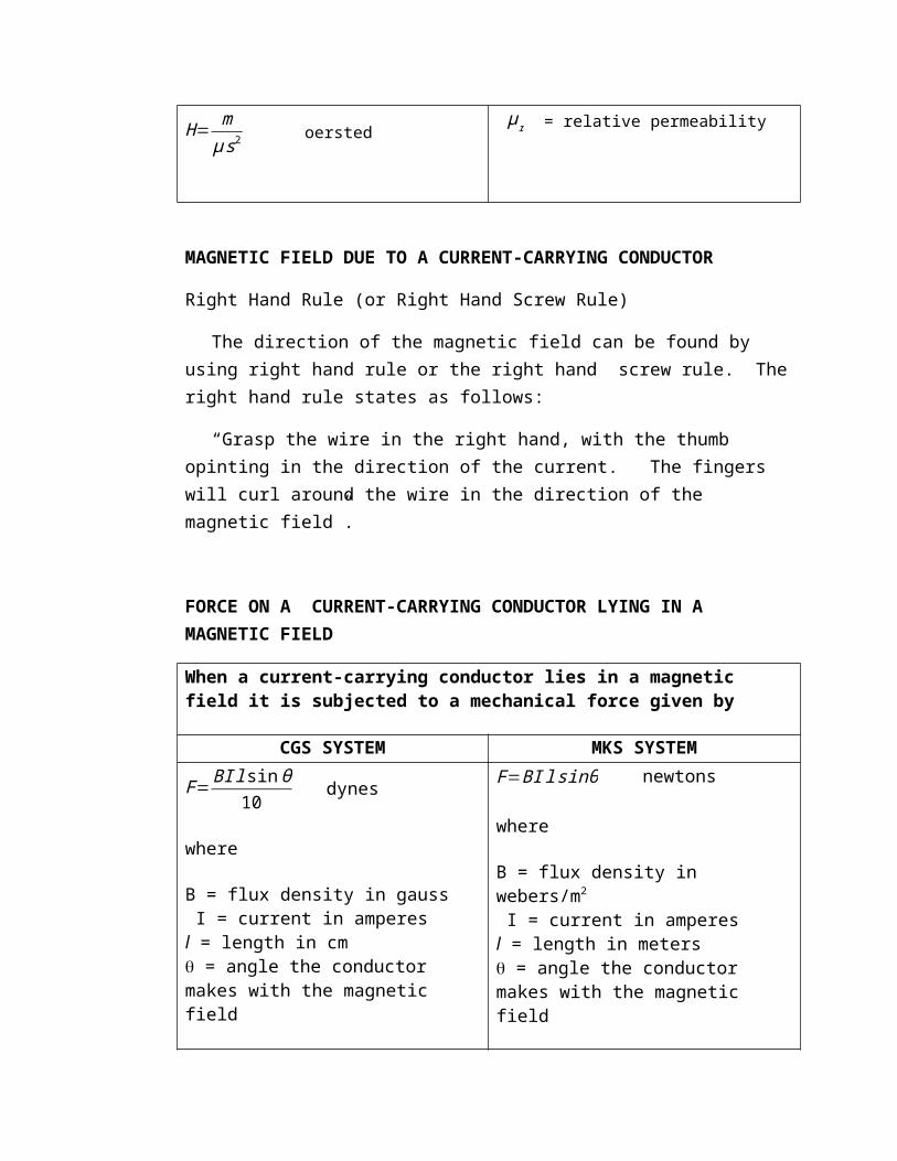
MAGNETIC FIELD DUE TO A CURRENT-CARRYING CONDUCTORRight Hand Rule (or Right Hand Screw Rule)
The direction of the magnetic field can be found by using right hand rule or the right hand screw rule. The right hand rule states as follows:“Grasp the wire in the right hand, with the thumb opinting in the direction of the current. The fingers will curl around the wire in the direction of the magnetic field”.
FORCE ON A CURRENT-CARRYING CONDUCTOR LYING IN A MAGNETIC FIELDWhen a current-carrying conductor lies in a magnetic field it is subjected to a mechanical force given by
CGS SYSTEM MKS SYSTEM

F=BI l sinθ10
dyneswhereB = flux density in gauss I = current in amperesl = length in cm = angle the conductor makes with the magnetic field
F=BI l sinθ newtonswhereB = flux density in webers/m2 I = current in amperesl = length in meters = angle the conductor makes with the magnetic field
The direction of this force may be easily found by Fleming’s left hand rule which states as follows:“Hold your left hand with index finger, middle finger and thumb at right angles. If the index finger points in the direction of the flux from north to south and middle finger points in the direction of the imposed voltage and its resulting conventional current flow, the thumb will point in the direction of the force that is developed.”
Field strength at the center of the circular coilCGS SYSTEM MKS SYSTEM

H=2∋ ¿10 r
¿ oerstedwhereN = number of turns I = current in amperesr = radius of coil in cm
H= ¿2 r ampere-turns/m
whereN = number of turns I = current in amperesr = radius of coil in meter
Magnetic Field due to a Long Straight Current-Carrying ConductorsCGS SYSTEM MKS SYSTEM
H= 2 I10 s
oerstedwhereI = current in amperess = distance from the wire in cm
H= I2 s
ampere-turns/mwhereI = current in amperess = distance from the wire in meter
Magnetic Field due to a Long Current-Carrying Straight SolenoidCGS SYSTEM MKS SYSTEM
H=4∋ ¿10 l
¿ oerstedwhereN= no. of turnsI = current in amperesl = axial length of solenoid in cm
H=¿l ampere-turns/m
whereN= no. of turnsI = current in amperesl = axial length of solenoid in meter

The same equation is used in determining the field intensity within a toroid. Simply replace l by the mean circumference of the toroid.Force between Long Straight Conductors
CGS SYSTEM MKS SYSTEMF=
μ I A I B l
100 s dynes
whereμ = permeabilityI A∧I B = current in amperess = distance between conductors in meters
F=μo I A I B l
2 s newtonsor
F=2x 10⁻⁷ I A I B l
s newtons
whereI A∧I B = current in amperess = distance between conductors in metersl = axial length of solenoid in meter
MAGNETIC CIRCUITSflux=
magnetomotive force (mmf )reluctance
¿ IR
CGS MKS = flux in maxwellsmmf (I) = 0.4NI gilbertsN = no. of turnsI = current in amperesR = reluctance in gilberts/maxwells
= flux in webersmmf (I) = NI ampere-turnsN = no. of turnsI = current in amperesR = reluctance in ampere-turns/weber
R= lµo µr Al = length of the magnetic circuit in cmA = area of the magnetic circuit in cm2
R= lµo µr Al = length of the magnetic circuit in mA = area of the magnetic circuit in m2
Comparison Between Magnetic and Electric Circuits.Magnetic Circuit Electric Circuit
1.Flux= mmfreluctance
2. mmf (ampere-turns)3. flux (webers)4. flux density B B=A Wb/m25. Reluctance6. Permeance (= 1/reluctance)7. Reluctivity8. Permeability (=1/reluctivity)9. Total mmf = R1+R2+R3 + . . .
1.Current= emfresistance
2. emf (volts)3. current I (amperes)4. Current density (A/m2)5. Resistance6. Conductance 7. Resistivity8. Conductivity9. Total emf = IR1 + IR2 + IR3 + . . . .

Problem Set No. 1MAGNETIC CIRCUITS1. Draw the magnetic line of force around the conductor below and indicate their direction.
2. Mark the conventional current direction on the conductor below.
3. Draw the magnetic field around the coil below and indicate its direction.

4. Mark the conventional current direction and draw the magnetic field around the coil below.
5. What is the reluctance of a magnetic circuit in which a total flux of 2 x 10⁻³ Wb is created by a 5-A current flowing in a solenoid consisting of 200 turns of wire?6. What current must be passed through a 500-turn solenoid to produce a total flux of 1.2 mWb in a magnetic circuit whose reluctance is 2 x 10⁸ At/Wb?7. How much turns of wire are there in solenoid if a 500-mA current through it establishes a total flux of 8 x 10⁻⁴ Wb in a magnetic circuit whose reluctance is 5 x 10⁵ At/Wb?8. What total flux is created in a magnetic circuit whose reluctance is 2.5 x 10⁶ reciprocal henrys by a current of 1.2 A flowing in a 500-turn solenoid wound around the magnetic circuit?9. The magnetic circuit in No. 5 has a uniform cross-sectional area of 5 cm2 and an average path length of 25 cm. What is the permeability of the core material?10. The core of a solenoid consists of a brass cylinder 10 cm in length and 2 cm in diameter. What is its reluctance?

11. A piece of iron 10 cm in length and having a rectangular cross section of 1 x 2 cm has a reluctance of 1.25 x 196 At/Wb. What is the permeability of the iron?12. What is the flux density in the magnetic circuit of problems 5 and 9?13. Electric current in a solenoid with an inside diameter of 2 cm creates a flux density inside the solenoid of 0.2 T. What is the total flux inside the solenoid?14. A uniform magnetic circuit has a path length of 20 cm. what is the magnetizing force when a 500-mA current flows in an 800-turn coil wound on the magnetic circuit.15. A magnetic field strength of 2000 At/m produces a flux density of 1.0 T in a certain type of iron. What is its permeability at this flux density?16. The core for a low=loss inductor in a crossover filter is made from a piece of that plastic stock 6 mm thick and 24 mm wide by 15 cm long formed into a closed loop, 1200 turns of wire form a toroid winding on this form.17. A 120-mA current flowing in a 1500-turn toroid winding creates a flux density of 8 x 10⁻⁴ T in the magnetic core. What is the average path length of the core?Unit 2
INTRODUCTION TO MACHINERY PRINCIPLES

Learn the basics of rotational mechanics: angular velocity, angular acceleration, torque, and Newton’s law for rotation.Learn how to produce a magnetic field.Understand magnetic circuits.Understand the behavior of ferromagnetic materials.Understand hysteresis in ferromagnetic amterials.Understand Faraday’s law. Understand how to produce an induced force on a wire.Understand how to produce an induced voltage across a wire.Understand the operation of a simple linear machine.
LEARNING OUTCOMESAfter completing this unit, you are expected to:
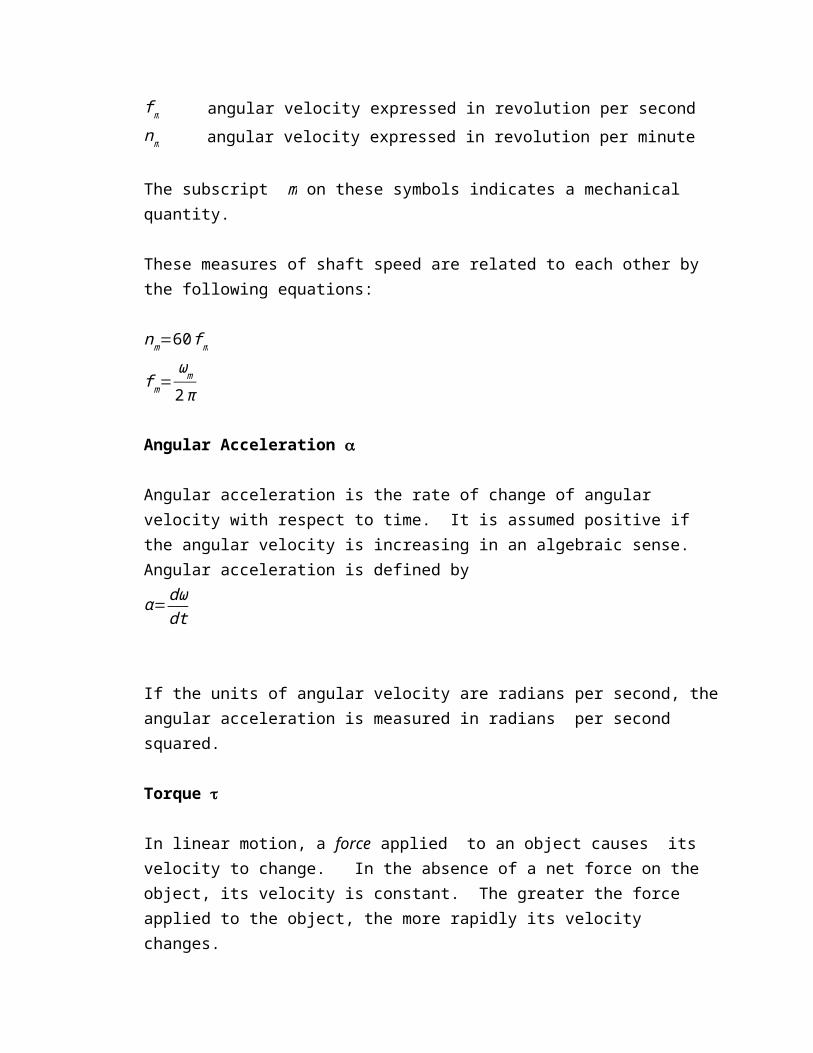
2.1 Rotational Motion, Newton’s Law, and Power RelationshipsAngular position The angular position of an object is the angle at which it is oriented, measured from some arbitrary reference point. Angular position is usually measured in radians or degrees.Angular Velocity Angular velocity (or speed) is the rate of change in angular position with respect to time. It is assumed positive if the rotation is in a counterclockwise direction. Angular velocity is defined as the rate of change of angular displacement with respect to time.
ω=dθdt

If the units of angular position are radians, then angular velocity is measured in radians per second.The following are used to describe angular velocity:ωm angular velocity expressed in radians per secondf m angular velocity expressed in revolution per secondnm angular velocity expressed in revolution per minuteThe subscript m on these symbols indicates a mechanical quantity.These measures of shaft speed are related to each other by the following equations:nm=60 f m
f m=ωm
2π
Angular Acceleration Angular acceleration is the rate of change of angular velocity with respect to time. It is assumed positive if the angular velocity is increasing in an algebraic sense. Angular acceleration is defined byα=dω
dt
If the units of angular velocity are radians per second, the angular acceleration is measured in radians per second squared.Torque In linear motion, a force applied to an object causes its velocity to change. In the absence of a net force on the object, its velocity is constant. The greater the force applied to the object, the more rapidly its velocity changes.

FTorque is counterclockwiseF = 0Torque is zero
r sin
There exists a similar concept for rotation. When an object is rotating, its angular velocity is constant unless a torque is present on it. The greater the torque on the object, the more rapidly the angular velocity of the object changes.What is torque? It can loosely be called the “twisting force” on an object.
The torque on an object is defined as the product of the force applied to the object and the smallest distance between the line of action of the force and the object’s axis of rotation. If r is a vector pointing from the axis of rotation to the point of application of the force, and if F is the applied force, then the torque can be described as = (force applied)(perpendicular distance) = (F)(r sin ) = rF sin
where is the angle between the vector r and the vector F. The units of torque are newton-meter in SI and pound-feet in the English system.

Newton’s Law of RotationNewton’s law for objects moving along a straight line describes the relationship between the force applied to an object and its resulting acceleration. This relationship is given by the equation
F = mawhereF = net force applied to an objectm = mass of the objecta = resulting accelerationIn SI units, force is measured in newtons, mass in kilograms, and acceleration in meters per second squared. In the English system, force in measured in pounds, mass in slugs, and acceleration in feet per second squared.A similar equation describes the relationship between the torque applied to an object and its resulting angular acceleration. This relationship, called Newton’s law of rotation, is given by the equation
= Jwhere is the net applied torque in newton-meters or pound-feet and is the resulting angular acceleration in radians per second squared. The term J serves the same purpose as an object’s mass in linear

motion. It is called the moment of inertia of the object and is measured in kilogram-meters squared or slug-feet squared.Work , WFor linear motion, work is defined as the application of a force through a distance.In equation form,
W = ∫Fdr
For the special case of a constant force applied collinearly with the direction of motion this equation becomes justW =Fr
The units of work are joules in SI and foot-pounds in the English system.For rotation motion, work is the application of a torque through an angle. Here the equation for work is
W = ∫ d
And if the torque is constant,W =¿
Power PPower is the rate of doing work, or the increase in work per unit time. The equation for power is
P= dWdt
It is usually measured in joules per second (watts), but also can be measured in foot-pounds per second or in horsepower.By this definition, and assuming that force is constant and collinear with the direction of motion, power is given by

P= dWdt
= ddt
( Fr )=F ( drdt )=F v
Similarly, assuming constant torque, power in rotational motion is given byP=dW
dt= d
dt()=( d
dt )=¿
P=¿
This equation is very important in the study of electric machinery, because it can describe the mechanical power on the shaft of a motor or generator. The equation is the correct relationship among power, torque, and speed if power is measured in watts, torque in newton-meters, and speed in radians per second. It is still common in U.S. engineering practice to measure torque in pound-feet, speed in revolutions per minute, and power in either watts or horsepower. If the appropriate conversion factors are included in each term, then the equation becomes
P(watts)=( lb−ft ) n(r /min)
7.04
P(horsepower )=(lb−ft ) n(r /min)
5252
where torque is measured in pound-feet and speed is measured in revolutions per minute.
Problem Set No. 2ROTATIONAL MOTION, NEWTON’S LAW, AND POWER RELATIONSHIPS
1. A motor’s shaft is spinning at a speed of 1800 r/min. what is the shaft speed in radians per second.2. A flywheel with a moment of inertia of 4 kgm2 is initially at rest. If a torque of 6 Nm (counterclockwise) is suddenly applied to the flywheel, what will be the speed of the flywheel after 5 s? Express the speed in both radians per second and revolutions per minute.3. A force of 10 N is applied to a cylinder of radius r = 0.15 m, as shown in Figure P11. The moment of inertia of this cylinder is J = 4 kgm2. What are the magnitude and direction of the torque produced by the cylinder? What are the angular acceleration of the cylinder?4. A motor is supplying 50 Nm of torque to its load. If the motor’s shaft is turning at 1500 r/min, what is the mechanical power supplied to the load in watts? In horsepower?

2.2 Faraday’s Law – Induced Voltage from a Time-Changing Magnetic FieldSo far, attention has been focused on the production of a magnetic field and on its properties. It is now time to examine the various ways in which an existing magnetic field can affect its surroundings.The first major effect to be considered is called Faraday’s law. It is the basis of transformer operation. Faraday’s law states that if a flux passes through a turn of a coil of wire, a voltage will be induced in the turn of wire that is directly proportional to the rate of change in the flux with respect to time. In equation form,
e ind=−ddt
where e ind is the voltage induced in the turn of the coil and is the flux passing through the turn. If a coil has N turn and if the flux passes through all of them, then the voltage induced across the whole coil is given bye ind=−N
ddtwhere
e ind= voltage induced in the coilN = number of turns of wire in coil = flux passing through coil
The minus sign in the equations is an expression of Lenz’s law. Lenz’s law states that the direction of the voltage buildup in the coil is such that if the coil ends where short circuited, it will produce current that would cause a flux opposing the original flux change. Since the induced voltage opposes the change that causes it, a minus sign is included in the equation. To understand this concept clearly, examine Figure 2.1 If the flux shown in the figure is increasing in strength,

increasingDirection of opposing flux
+eind_
Direction of required
= 0.05 sin 377t WbDirection of opposing flux
+eind_
Direction of required
then the voltage built up in the coil will tend to establsih a flux that will oppose the incraese. A current flowing as shown in Figure 2.1b would produce a flux opposing the incraese, so the voltage on the coil must be built up with the polarity required to drive through that current throught the external circuit. Since the polarity of the resulting voltage can be determined from physical considerations, the minus sign is often left out.
(a) (b)Figure 2.1. The meaning of Lenz’s law: (a) A coil enclosing an increasing magnetic flux; (b) determining the resulting voltage polarity
Figure 2.2 . The core of Example 2.1. Determination of the voltage polarity at the terminals is shown.
N = 100 turns turns

Example 2.1 Figure 2.2 shows a coil of wire wrapped around an iron core. The flux in the core is given by the equation.¿0.05sin 377 tWbIf there are 100 turns on the core, what voltage is produced at the terminals of the coil? Of what polarity is the voltage during the time when flux is increasing in the reference direction in the figure? Assume that all the magnetic flux stays within the core (i.e., assume that the flux leakage is zero).SolutionThe direction of the voltage while the flux is increasing in the reference direction must be positive to negative, as shown in the figure. The magnitude of the voltage is given bye ind=N
ddt
¿ (100 turns ) ddt
¿
¿1885cos377 t
or alternativelye ind=1885sin (377 t+90° )VEddy Current Loss
A time-changing flux induces voltage within a ferromagnetic core in just the same manner as it would in a wire wrapped around the core. These voltages cause swirls of current to flow within the core, much

F B
like the eddies seen at the edges of a river. It is the shape of these currents that gives rise to the name eddy currents. These eddy currents are flowing in a resistive material (the iron of the core), so energy is dissipated by them. The lost energy goes into heating the iron core. Two possible causes to reduce the eddy current losses in an electric machine:
1. Use laminated core.2. Increase the resistivity of the core material by adding some silicon to the steel of the core.
2.3 Production of Induced Force on a Wire
Figure 2.3. A current-carrying wire in the presence of a magnetic field.A second major effect of a magnetic field on its surroundings is that it induces a force on a current-carrying wire within the field. The basic concept involved is illustrated in Figure 2.3. The figure shows a conductor present in a uniform magnetic field of flux density B, pointing into the page. The conductor itself is l meters long and contains a current of i amperes. the force induced on the conductor is given by

F=i(l x B)
wherei = magnitude of current in wirel = length of wire, with direction of l defined to be in the direction of current flowB = magnetic flux density vector The direction of the force is given by the right-hand rule: If the index finger of the right hand points in the direction of the vector l and the middle finger points in the direction of the flux density vector B, then the thumb points in the direction of the resultant force on the wire. The magnitude of the force is given by the equation
F=ilB sinθ
where θ is the angle between the wire and the flux density vector.Example 2.2 Figure 2.3 shows a wire carrying a current in the presence of a magnetic field. The magnetic flux density is 0.25 T, directed into the page. If the wire is 1.0 m long and carries 0.5 A of current in the direction from the top of the page to the bottom of the page, what are the magnitude and direction of the force induced on the wire?SolutionThe direction of the force is given by the right-hand rule as being to the right. The magnitude is given by
F=ilB sinθ
F=(0.5 A ) (1m ) (0.25T )sin 90 °=0.125N
Therefore, F = 0.125 N, directed to the right.

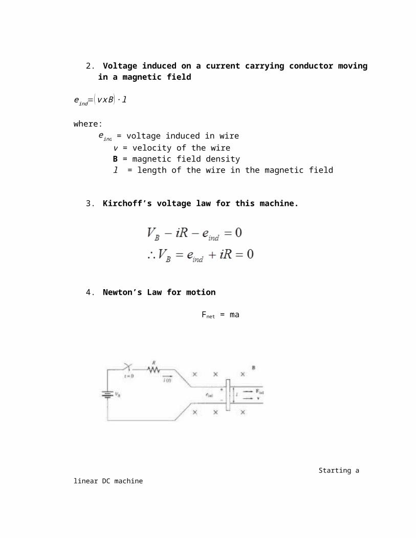
2.4 Induced Voltage on a Conductor Moving in a Magnetic FieldIf a conductor moves or ‘cuts’ through a magnetic field, voltage will be induced between the terminals of the conductor at which the magnitude of the induced voltage is dependent upon the velocity of the wire assuming that the magnetic field is constant. This can be summarised in terms of formulation as shown:e ind=( v x B ) ∙ l where: v = velocity of the wire B = magnetic field density l = length of the wire in the magnetic fieldVector l points the direction of the wire toward the end making the smalles angle with respect to the vector v x B. The vector in the wire will be built up so that the positive end is the in the direction of the vector v x B. Example 2.3 In Figure 2.4 shows a conductor moving with a velocity of 5 m/s to the right in the presence of a magnetic field. The flux density is 0.5 T into the page, and the wire is 1.0 m in length, oriented as shown. What are the magnitude and polarity of the resulting induced voltage?
The induction of a force in a wire by a current in the presence of a magnetic field is the basis of motor action. Almost every type of motor depends on this basic principle for the forces and torques which make it move.
eind
v x B
v

30°
Figure 2.4. A conductor moving in the presence of a magnetic fieldSolutionThe direction of the quantity v x B in this example is up. Therefore, the voltage of the conductor is up positive at the top with respect to the bottom of the wire. The direction of vector l is up, so that it makes the smalles angle with respect to the vector v x B.Since v is perpendicular to B and since v x B is parallel to l, the magnitude of the induced voltage reduces toe ind=( v x B ) ∙ l ¿¿ ¿ vBl ¿(5.0m
s ) (0.5T )(1.0m) ¿2.5 VThus the induced voltage is 2.5 V, positive at the top of the wire.
v
v x B
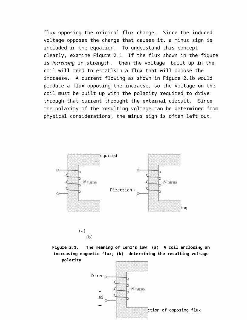
Figure 2.5 The conductor in Example 2.4Example 2.4 Figure 2.5 shows a conductor moving with a velocity of 10 m/s to the right in a magnetic field. The flux density is 0.5 T, out of the page, and the wire is 1.0 m in length, oriented as shown. What are the magnitude and polarity of the rsulting induced voltage?SolutionThe direction of the quantity v x B is dwon. The wire is not oriented on an up-down line, so choose the direction of l as shown to make the smallest possible angle with the direction of v x B. The voltage is positive at the bottom of the wire with respect to the top of the wire. The magnitude of the voltage is e ind=( v x B ) ∙ l ¿¿ ¿ vBl ¿(10.0m
s ) (0.5T )(1.0m)cos30 ° ¿4.33 V
2.5 The Linear DC MachineLinear DC machine is the simplest form of DC machine which is easy to understand and it operates according to the same principles and exhibits the same behaviour as motors and generators. Consider the following:
The induction of voltages in a wire moving in a magnetic field is fundamental to the operation of all types of generators. For this reason, it is called generator action.

Equations needed to understand linear DC machines are as follows:1. Production of Force on a current carrying conductor
F=i(l x B)whereF = force on wirei = magnitude of current in wirel = length of wire, with direction of l defined to be in the direction of current flowB = magnetic flux density vector
2. Voltage induced on a current carrying conductor moving in a magnetic fielde ind=( v x B ) ∙ l where:
e ind = voltage induced in wire v = velocity of the wire B = magnetic field density l = length of the wire in the magnetic field3. Kirchoff’s voltage law for this machine.

4. Newton’s Law for motionFnet = ma
Starting a linear DC machine2.6 Starting the Linear DC Machine1. To start the machine, the switch is closed.2. Current will flow in the circuit and the equation can be derived from Kirchhoff’s law:
i=V B−e ind
R
At this moment, the induced voltage is 0 due to no movement of the wire (the bar is at rest). e ind=0, so i=V B
R.
3. As the current flows down through the bar, a force will be induced on the bar. (Section 1.6 a current flowing through a wire in the presence of a magnetic field induces a force in the wire).

Direction of movement: Right 4. When the bar starts to move, its velocity will increase, and a voltage appears across the bar.
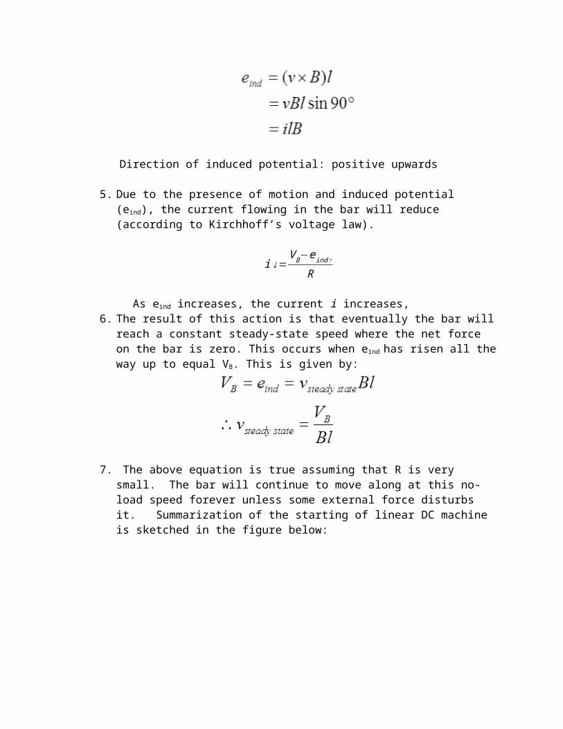
Direction of induced potential: positive upwards5. Due to the presence of motion and induced potential (eind), the current flowing in the bar will reduce (according to Kirchhoff’s voltage law).
i↓=V B−eind ↑
R
As eind increases, the current i increases,6. The result of this action is that eventually the bar will reach a constant steady-state speed where the net force on the bar is zero. This occurs when eind has risen all the way up to equal VB. This is given by:
7. The above equation is true assuming that R is very small. The bar will continue to move along at this no-load speed forever unless some external force disturbs it. Summarization of the starting of linear DC machine is sketched in the figure below:

2.7 The Linear DC Machine as a Motor1. Assume the linear machine is initially running at the no-load steady state condition (as before).2. What happen when an external load is applied? See figure below:
3.
A force Fload is applied to the bar opposing the direction of motion. Since the bar was initially at steady state, application of the force Fload will result in a net force on the bar in the direction opposite the direction of motion.

4. Thus, the bar will slow down (the resulting acceleration a = Fnet/m is negative). As soon as that happen, the induced voltage on the bar drops (eind = v↓ Bl).5. When the induced voltage drops, the current flow in the bar will rise:
6. Thus, the induced force will rise too. (Find ↑ = i↑ lB)7. Final result : the induced force will rise until it is equal and opposite to the load force, and the bar again travels in steady state condition, but at a lower speed. See graphs below:
8. Now, there is an induced force in the direction of motion and power is being converted from electrical to mechanical form to keep the bar moving.

9. The power converted is Pconv = eindI = Find v . An amount of electric power equal to eind i is consumed and is replaced by the mechanical power Find v . Since power is converted from electrical to mechanical form, this bar is operating as motor.10. The power converted in a real rotating motor is: Pconv= τind ω2.8 The Linear DC Machine as a Generator1. Assume the linear machine is operating under no-load steady-state condition. A force in the direction of motion is applied.
2. The applied force will cause the bar to accelerate in the direction of motion, and the velocity vwill increase.3. When the velocity increase, eind= V ↑ Bl will increase and will be larger than VB. 4. When eind > VB the current reverses direction.5. Since the current now flows up through the bar, it induces a force in the bar (Find= ilB to the left). This induced force opposes the applied force on the bar.6. End result the induced force will be equal and opposite to the applied force, and the bar will move at a higher speed than before. The linear machine no is converting mechanical power Find v to electrical power eind i

7. The amount of power converted : Pconv= τindωNOTE:The same machine acts as both motor and generator. The only difference is whether the externally applied force is in the direction of motion (generator) or opposite to the direction of motion (motor).
Electrically, eind> VB in a generatoreind < VB in a motorWhether the machine is a motor or a generator, both induced force (motor action) or induced voltage (generator action) is present at all times.Both actions are present, and it is only thevrelative directions of the external forces with respect to the direction of motion that determine whether the overall machine behaves as a motor or as a generator.The machine was a generator when it moved rapidly and a motor when it moved more slowly. But, whether it was a motor or a generator, it always moved in the same direction.There is a merely a small change in operating speed and a reversal of current flow.
2.9 Starting Problems with the Linear MachineA linear machine is shown in Figure 2.6. This machine is supplied by a 250-V DC source, and its internal resistance is given as about 0.10 Ω. (The resistor R models the internal resistance of a real DC machine, and this is fairly reasonable internal resistance for a medium-size DC motor.)At starting conditions, the speed of the bar is zero, so e ind = 0. The current flow at starting is
istart=V B
R= 250V0.10Ω
=2500 A
Figure 2.6 The linear DC machine with component values illustrating the problem of excessive starting current
This current is very high, often in excess of 10 times the rated current of the machine, such current can cause severe damage to a motor. Both real AC and real DC machines suffer from high-current problems on starting.How can such damage be prevented? The easiest method for this simple liner DC machine is to insert an extra resistance into the circuit during starting to limit the current flow until e ind build up enough to limit it.
Figure 2.7. A linear DC machine with an extra series resistor inserted to control the starting current.
l = 0.5 m
= 0.5 T, directed into the page 0.10 Ω
i(t)
250 V

Example 2.5 The linear DC machine shown in Figure 2.8(a) has a battery voltage of 120 V, an internal resistance of 0.3 Ω, and a magnetic flux density of 0.1 T.(a) What is the machine’s starting current? What is the steady-state velocity at no load?(b)Suppose that a 30-N force pointing to the right were applied to the bar, what would the steady-state speed be? How much power would the power be producing or consuming? How much power would the battery be producing or consuming?Explain the difference between these figures. Is this machine acting as a motor or as a generator?(c)Now suppose a 30-N force pointing to the left were applied to the bar. What would the new steady-state speed be? Is this machine a motor or a generator now?(d)Assume that a force pointing to the left is applied to the bar. Calculate speed of the bar as a function of the force for value from 0 N to 50 N in 10-N speed. Plot the velocity of the bar versus the applied force.(e)Assume that the bar is unloaded and that it suddenly runs into a region where the magnetic field is weakened to 0.08. how fast will the bar go now?
Solution(a) At starting condition, the velocity of the bar is 0, so e ind = 0. Therefore,
istart=V B−eind
R=120V −0V
0.3Ω=4 00 A
When the machine reaches steady state, F ind=0 and i=0. Therefore,V B=e ind=v ss Bl
vss=V B
Bl
¿ 120V(0.1T )(10m)
=120m / s
(b)Refer to Figure 2.8b. If a 30-N force to the right is applied to the bar, the final steady state will occur when the induced force F ind is equal and opposite to the applied force Fapp so that the net force on the bar is zero.
Fapp=Find=ilBTherefore,i=
Find
lB= 30N
(10m)(0.1T )
¿30 A flowing up through the ¿
The induced voltage e ind on the bar must bee ind=V B+ iR
e ind=120V +(30 A ) (0.3Ω)=120V
and the final steady-state speed must be
vss=eind
Bl
¿ 129V(0.1T )(10m)
=129m / s
The bar is producing P = (129 V)(30 A) = 3870 W of power, and the battery is consuming P = (120 V)(30 A) = 3600 W. the difference between these two numbers is the 270 W of losses in the resistor. This machine is acting as a generator. (c)Refer to Figure 2.8c. This time, the force is applied to the left, and the induced force is to the right. At steady state,

Fapp=Find=ilB
i=Find
lB= 30N
(10m)(0.1T )
¿30 A flowing downthrough the ¿
The induced voltage e ind on the bar must be (d)E(e)E(f)


![L 25 Electricity and Magnetism [3]](https://img.dokumen.tips/doc/110x75/56816754550346895ddc0936/l-25-electricity-and-magnetism-3.jpg)
![L 26 Electricity and Magnetism [3]](https://img.dokumen.tips/doc/110x75/56813d55550346895da71510/l-26-electricity-and-magnetism-3-568dd9a9518fb.jpg)