Embed Size (px)
Citation preview

COMPANY PROFILE
50 HZ HF CONVERSION MEASURING FILTERING
TWO TECHNOLOGIES POWER
1996 2001 Trend
ASIE18%
EUROPE40%
USA42 %
Myrra is a major supplier in high quality for electronics components. Myrra has establisheda worldwide reputation.
A wide range of products : We offer application specific transformers, inductors, chokes andcoils, in two technologies high frequency and 50 hz technology, enabling us to serve a numberof major markets.
MAGNETICS PRODUCTS
SALES TURNOVER


FLYBACK TRANSFORMERS RANGE TRANSFORMERS/CONTROL CIRCUITS CROSS REFERENCE LIST 1 TO 9 W EE 16 74090 – 74091 – 74092 – 74093 – 74094 – 74095 1 TO 6 W EE 16 74000 – 74001 – 74002 – 74003 6 TO 12 W EE 16 74010 – 74014 – 74015 10 TO 18 W EL 19 74020 – 74021 – 74023 12 TO 24 W EF 20 74080 – 74081 – 74082 15 TO 30 W EE 25 74030 – 74032 35 TO 60 W ETD 29 74040 35 TO 60 W ERL 28 74043 60 TO 90 W ETD 34 74050 70 TO 140 W ETD 39 74060 120 TO 180 W ETD 44 74070
TOROIDAL CHOKES 32
POWER FERRITE TRANSFORMERS 6 to 26
DRUM CORE CHOKES 33
CURRENT TRANSFORMERS RANGE 34 to 45
PULSE TRANSFORMERS RANGE 46 to 51
POWER LINE COMMUNICATION COUPLING TRANSFORMERS 52 to 53
COMMON MODE CHOKES FOR EMI SUPPRESSION 27 to 31
PRODUCT INDEX
FOR MOSFET OR IGBT CONTROL, SCR TRIGGERING, DC/DC CONVERSION
FOR MAINS AC CURRENT MEASUREMENT 50 TO 400 HZ FOR SWITCH MODE POWER SUPPLIES 20 TO 150 KHZ
DIMMER CHOKES FOR EMI SUPPRESSION

6
FLYBACK TRANSFORMERS RANGEfor switch mode power supplies
Note : “5 volts” outputs can generally be used for 3.3 to 6volts; “12 volts” outputs can be used for 9 to 16volts.See detailed characteristics.
Watts
MYRRAPart N°
Max.OutputPower
Vdc nominal voltage
CORESIZE
Outputs
74000 E16 5w 5v 12v
74001 E16 6w 5v
74002 E16 6w 12v
74003 E16 5w 3.3v 5v
74010 E16 12w 5v 12v
74014 E16 12w 24v 24v
74015 E16 12w 5v 15v 24v
74020 EL19 18w 5v 12v
74021 EL19 18w 5v 12v
74023 EL19 16w 3.3v 5v 12v 18v 30v
74030 E25 30w 5v 12v 12v
74032 E25 35w 24v
74040 ETD29 60w 5v 12v 5v 12v
74043 ERL28 60w 3.3v 5v 12v 18v 30v
74050 ETD34 90w 5v 12v 5v 12v
74060 ETD39 140w 5v 12v 5v 12v
74070 ETD44 180w 5v 12v 5v 12v
74080 EF20 24w 12v 12v
74081 EF20 20w 3.3v 5v 12v
74082 EF20 20w 5v 5v
74090 E16 1.5w 5v
74091 E16 1.5w 12v
74092 E16 3.1w 5v
74093 E16 3.1w 12v
74094 E16 9w 5v
74095 E16 9w 12v

7
TRANSFORMER / CONTROL CIRCUITSCROSS-REFERENCE LIST
Power Integrations TOP244P 74032 25w
Power Integrations TOP244Y 74030 25w
Power Integrations TOP245Y 74040 60w
Power Integrations TOP246Y 74043 60w
Power Integrations TOP246Y 74050 90w
Power Integrations TOP247Y 74060 140w
Power Integrations TOP248Y 74070 180w
Power Integrations TOP249Y 74070 120w
Infineon TDA16831 74001 6w
Infineon TDA16831 74002 6w
Infineon TDA16831 74003 6w
Infineon TDA16831 74010 10w
Infineon TDA16831 74021 10w
Infineon TDA16832 74020 16w
Infineon TDA16832 74030 30w
Infineon TDA16834 74040 35w
Infineon TDA16834 74040 45w
Infineon TDA16834 74050 80w
Infineon TDA16836 74050 60w
Infineon TDA16836 74060 70w
Infineon TDA16836 74060 120w
Infineon TDA16837 74070 160w
ON Semiconductors MC33369 74001 6w
ON Semiconductors MC33369 74002 6w
ON Semiconductors MC33369 74003 6w
ON Semiconductors MC33369 74010 10w
ON Semiconductors MC33370 74020 16w
ON Semiconductors MC33370 74021 13w
ON Semiconductors MC33371 74030 30w
ON Semiconductors MC33372 74040 45w
ON Semiconductors MC33373 74050 80w
ON Semiconductors MC33374 74060 120w
Philips TEA1566 74070 120w
Fairchild KA5H0165RN 74010 10w
Fairchild KA5L0165R 74010 7w
Fairchild KA1H0265R 74030 22w
Fairchild KA1H0565R 74060 70w
Fairchild KA2S0965 74070 160w
ST Microelectronics VIPer100A 74050 80w
ST Microelectronics VIPer100A 74060 120w
ST Microelectronics VIPer20 74000 4w
ST Microelectronics VIPer20 74001 6w
ST Microelectronics VIPer20 74002 6w
ST Microelectronics VIPer20 74003 6w
ST Microelectronics VIPer20 74010 10w
ST Microelectronics VIPer20 74020 12w
ST Microelectronics VIPer50 74020 16w
ST Microelectronics VIPer50 74021 13w
ST Microelectronics VIPer50 74030 30w
ST Microelectronics VIPer50 74040 45w
Power Integrations TNY253 74090 1.5w
Power Integrations TNY253 74091 1.5w
Power Integrations TNY254 74092 3.1w
Power Integrations TNY254 74093 3.1w
Power Integrations TNY255 74094 4.2w
Power Integrations TNY255 74095 5w
Power Integrations TNY264 74094 5w
Power Integrations TNY264 74095 5w
Power Integrations TNY266 74014 12w
Power Integrations TNY266 74015 10w
Power Integrations TNY266 74094 9w
Power Integrations TNY266 74095 9w
Power Integrations TNY267 74010 12w
Power Integrations TNY268 74020 15w
Power Integrations TNY268 74082 17w
Power Integrations TOP242P 74000 5w
Power Integrations TOP242P 74001 6w
Power Integrations TOP242P 74002 6w
Power Integrations TOP242P 74003 5w
Power Integrations TOP242P 74010 12w
Power Integrations TOP242P 74014 12w
Power Integrations TOP242P 74015 12w
Power Integrations TOP243P 74020 18w
Power Integrations TOP243P 74023 16w
Power Integrations TOP243P 74080 24w
Power Integrations TOP243P 74081 20w
Power Integrations TOP243P 74082 20w
Power Integrations TOP243Y 74021 18w
Power Integrations TOP244P 74030 30w
IC IC Transformer PowerManufacturer reference reference
IC IC Transformer PowerManufacturer reference reference


9
SIZE E16 • SINGLE OUTPUT : 5 or 12vTRANSFORMERFOR TINYSWITCH
• Primary / Secondary Insulation ≥ 4000V• Creepage distance Primary / Secondary ≥ 6mm• Ambient temperature < 85°C• Construction conforms to IEC950, IEC335, IEC61558 for reinforced insulation • Exclusively uses UL94-V0 listed materials
Pin 3 Removed PCB Drilling Diameter = 1.1mmBottom View (Pin side)
0V +S1
DRAIN+E
Examples of application with Integrated Circuits :
MYRRAP / N
WindingsOutputPower
maximum Pins Turns VoltageCurrent
maximumInductance(+/-10%)
74090 1.5 w Pri 10 – 9 228 50 – 95 (VOR) 0.28 Apeak 6000µH
S1 5 – 2 16 3.3 – 6 Vdc 0.4 Adc
74091 1.5 w Pri 10 – 9 228 65 – 130 (VOR) 0.28 Apeak 6000µH
S1 5 – 2 28 7.5 – 15 Vdc 0.2 Adc
74090 Power Integrations TNY253 85 - 265Vrms 1.5w 44kHz
74091 Power Integrations TNY253 85 - 265Vrms 1.5w 44kHz
MYRRAP / N
FrequencyControl IC
ManufacturerControl IC
P / NInput voltage Power

10
• Primary / Secondary Insulation ≥ 4000V• Creepage distance Primary / Secondary ≥ 6mm• Ambient temperature < 70°C• Construction conforms to IEC950, IEC335, IEC61558 for reinforced insulation • Exclusively uses UL94-V0 listed materials
Pin 3 Removed PCB Drilling Diameter = 1.1mmBottom View (Pin side)
0V +S1
DRAIN+E
Examples of application with Integrated Circuits :
SIZE E16 • SINGLE OUTPUT : 5 or 12v TRANSFORMERFOR TINYSWITCH
74092 3.1 w Pri 10 – 9 191 55 – 100 (VOR) 0.34 Apeak 4200µH
S1 5 – 2 13 3.3 – 6 Vdc 0.9 Adc
74093 3.1 w Pri 10 – 9 191 65 – 125 (VOR) 0.34 Apeak 4200µH
S1 5 – 2 24 7.5 – 15 Vdc 0.4 Adc
MYRRAP / N
WindingsOutputPower
maximum Pins Turns VoltageCurrent
maximumInductance(+/-10%)
74092 Power Integrations TNY254 85 - 265Vrms 3.1w 44kHz
74093 Power Integrations TNY254 85 - 265Vrms 3.1w 44kHz
MYRRAP / N
FrequencyControl IC
ManufacturerControl IC
P / NInput voltage Power

11
SIZE E16 • SINGLE OUTPUT : 5 or 12vTRANSFORMERFOR TINYSWITCH
• Primary / Secondary Insulation ≥ 4000V• Creepage distance Primary / Secondary ≥ 6mm• Ambient temperature < 60°C• Construction conforms to IEC950, IEC335, IEC61558 for reinforced insulation • Exclusively uses UL94-V0 listed materials
Pin 3 Removed PCB Drilling Diameter = 1.1mmBottom View (Pin side)
0V +S1
DRAIN+E
74094 9 w Pri 10 – 9 135 55 – 100 (VOR) 0.48 Apeak 2100µH
S1 5 – 2 9 3.3 – 6 Vdc 1.5 Adc
74095 9 w Pri 10 – 9 135 65 – 125 (VOR) 0.48 Apeak 2100µH
S1 5 – 2 17 7.5 – 15 Vdc 0.9 Adc
MYRRAP / N
WindingsOutputPower
maximum Pins Turns VoltageCurrent
maximumInductance(+/-10%)
Examples of application with Integrated Circuits :
74094 Power Integrations TNY255 85 - 265Vrms 4.2w 44kHz
Power Integrations TNY264 85 - 265Vrms 5w 132kHz
Power Integrations TNY266 85 - 265Vrms 9w 132kHz
74095 Power Integrations TNY255 85 - 265Vrms 5w 44kHz
Power Integrations TNY264 85 - 265Vrms 5w 132kHz
Power Integrations TNY266 85 - 265Vrms 9w 132kHz
MYRRAP / N
FrequencyControl IC
ManufacturerControl IC
P / NInput voltage Power

12
74000 5 w Pri 4 - 6 138 62 – 130 (VOR) 0.27 Apeak 3900µH
Aux 2 - 1 16 7 – 14 Vdc 0.1 Adc
S1 9 - 10 8 3.3 – 7 Vdc 1.2 Adc
S2 7 - 8 19 8 – 17 Vdc 0.4 Adc
SIZE E16 • 2 OUTPUTS : 5 & 12v FLYBACKTRANSFORMER
• Primary / Secondary Insulation ≥ 4000V• Primary / Auxiliary Insulation ≥ 1500V• Creepage distance Primary / Secondary ≥ 6mm• Ambient temperature < 70°C• Construction conforms to IEC950, IEC335, IEC61558 for reinforced insulation • Exclusively uses UL94-V0 listed materials
MYRRAP / N
OutputPower
maximum
Windings
Pins Turns VoltageCurrent
maximumInductance(+/-10%)
PIN 3 Removed PCB Drilling Diameter = 1.1mm
+S2 0V +S1 0V
+E DRAIN +AUX 0V
Bottom View (Pin side)
74000
Examples of application with Integrated Circuits :
74000 Power Integrations TOP242P 85 - 265Vrms 5w 132kHzST Microelectronics VIPer20 85 - 265Vrms 4w 70kHz
MYRRAP / N
Control ICManufacturer
Control ICP / N
Input voltage Power Frequency

13
SIZE E16 • SINGLE OUTPUT : 5 or 12vFLYBACKTRANSFORMER
• Primary / Secondary Insulation ≥ 4000V• Primary / Auxiliary Insulation ≥ 1500V• Creepage distance Primary / Secondary ≥ 6mm• Ambient temperature < 60°C• Construction conforms to IEC950, IEC335, IEC61558 for reinforced insulation • Exclusively uses UL94-V0 listed materials
PIN 3 Removed PCB Drilling Diameter = 1.1mm
+S1 0V
+E DRAIN +AUX 0V
Bottom View (Pin side)
MYRRAP / N
74001 Power Integrations TOP242P 85 - 265Vrms 6w 132kHz
ST Microelectronics VIPer20 85 - 265Vrms 6w 70kHz
ST Microelectronics VIPer20 85 - 265Vrms 3w 40kHz
Motorola MC33369 85 - 265Vrms 6w 100kHz
Infineon TDA16831 185 - 265Vrms 6w 100kHz
74002 Power Integrations TOP242P 85 - 265Vrms 6w 132kHz
ST Microelectronics VIPer20 85 - 265Vrms 6w 70kHz
ST Microelectronics VIPer20 85 - 265Vrms 3w 40kHz
Motorola MC33369 85 - 265Vrms 6w 100kHz
Infineon TDA16831 185 - 265Vrms 6w 100kHz
Frequency
74001 6 w Pri 4 - 6 138 60 – 120 (VOR) 0.35 Apeak 3000µH
Aux 2 - 1 20 8 – 16 Vdc 0.1 Adc
S1 9 - 10 8 3 – 6 Vdc 1.2 Adc
74002 6 w Pri 4 - 6 150 60 – 120 (VOR) 0.38 Apeak 3000µH
Aux 2 - 1 22 8.5 – 17 Vdc 0.1 Adc
S1 9 - 10 24 9 – 18 Vdc 0.5 Adc
Windings
MYRRAP / N
OutputPower
maximum Pins Turns VoltageCurrent
maximumInductance(+/-10%)
Examples of application with Integrated Circuits :
Control ICManufacturer
Control ICP / N
Input voltage Power

14
• Primary / Secondary Insulation ≥ 4000V• Primary / Auxiliary Insulation ≥ 1500V• Creepage distance Primary / Secondary ≥ 6mm• Ambient temperature < 60°C• Construction conforms to IEC950, IEC335, IEC61558 for reinforced insulation • Exclusively uses UL94-V0 listed materials
PIN 3 Removed PCB Drilling Diameter = 1.1mmBottom View (Pin side)
+S2 +S1 0V
+E DRAIN +AUX 0V
74003
MYRRAP / N
Frequency
Examples of application with Integrated Circuits :
Control ICManufacturer
Control ICP / N
Input voltage Power
SIZE E16 • DUAL OUTPUT : 3.3 + 5v FLYBACKTRANSFORMER
74003 Power Integrations TOP242P 85 - 265Vrms 5w 132kHz
ST Microelectronics VIPer20 85 - 265Vrms 6w 70kHz
ST Microelectronics VIPer20 85 - 265Vrms 3w 40kHz
Motorola MC33369 85 - 265Vrms 6w 100kHz
Infineon TDA16831 185 - 265Vrms 6w 100kHz
MYRRAP / N
OutputPower
maximum
Windings
Pins Turns VoltageCurrent
maximumInductance(+/-10%)
74003 6 w Pri 4 - 6 120 55 – 115 (VOR) 0.3 Apeak 3000µH
Aux 2 - 1 17 8 – 16 Vdc 0.1 Adc
S1 9 - 10 5 2 – 4 Vdc 1.8 Adc
S2 7 - 10 7 3 – 6 Vdc 1.2 Adc

15
SIZE E16 • 2 OUTPUTS : 5 & 12vFLYBACKTRANSFORMER
• Primary / Secondary Insulation ≥ 4000V• Primary / Auxiliary Insulation ≥ 1500V• Creepage distance Primary / Secondary ≥ 6mm• Ambient temperature < 50°C• Construction conforms to IEC950, IEC335, IEC61558 for reinforced insulation • Exclusively uses UL94-V0 listed materials
PIN 3 Removed PCB Drilling Diameter = 1.1mm
+S2 0V +S1 0V
+E DRAIN +AUX 0V
Bottom View (Pin side)
74010
Examples of application with Integrated Circuits :
MYRRAP / N
74010 12 w Pri 4 - 6 120 60 – 125 (VOR) 0.55 Apeak 1660µH
Aux 2 - 1 14 7 – 14 Vdc 0.1 Adc
S1 9 - 10 7 3.3 – 7 Vdc 2 Adc
S2 7 - 8 17 8 – 17 Vdc 1 Adc
WindingsOutputPower
maximum Pins Turns VoltageCurrent
maximumInductance(+/-10%)
MYRRAP / N
FrequencyControl IC
ManufacturerControl IC
P / NInput voltage Power
74010 Power Integrations TNY267 185 - 265Vrms 12w 132kHz
Power Integrations TOP242P 85 - 265Vrms 10w 132kHz
Power Integrations TOP242P 185 - 265Vrms 12w 132kHz
Power Integrations TOP242P 85 - 265Vrms 10w 132kHz
Power Integrations TOP242P 185 - 265Vrms 12w 132kHz
ST Microelectronics VIPer20 85 - 265Vrms 8w 70kHz
ST Microelectronics VIPer20 185 - 265Vrms 10w 70kHz
Motorola MC33369 85 - 265Vrms 8w 100kHz
Motorola MC33369 185 - 265Vrms 10w 100kHz
Infineon TDA16831 92 - 265Vrms 7,5w 100kHz
Infineon TDA16831 185 - 265Vrms 10w 100kHz
Fairchild KA5L0165R 85 - 265Vrms 7w 50kHz
Fairchild KA5H0165RN 185 - 265Vrms 10w 100kHz

16
• Primary / Secondary Insulation ≥ 4000V• Primary / Auxiliary Insulation ≥ 1500V• Creepage distance Primary / Secondary ≥ 6mm• Ambient temperature < 50°C• Construction conforms to IEC950, IEC335, IEC61558 for reinforced insulation • Exclusively uses UL94-V0 listed materials
PIN 3 Removed PCB Drilling Diameter = 1.1mm
+S2 0V +S1 0V
+E DRAIN +AUX 0V
Bottom View (Pin side)
74014
Examples of application with Integrated Circuits :
SIZE E16 • 2 OUTPUTS : 2 x 24v FLYBACKTRANSFORMER
Typical outputs : +24V 0.5A with S1 – S2 in parallel+48V 0.25A with S1 – S2 in series (8-9 connected)+15V / -15V 0.4A with pins 8-9 connected to 0V
MYRRAP / N
OutputPower
maximum
Windings
Pins Turns VoltageCurrent
maximumInductance(+/-10%)
74014 12 w Pri 4 - 6 120 70 – 140 (VOR) 0.5 Apeak 1800µH
Aux 2 - 1 17 9 – 18 Vdc 0.2 Adc
S1 9 - 10 27 15 – 30 Vdc 0.4 Adc
S2 7 - 8 27 15 – 30 Vdc 0.4 Adc
MYRRAP / N
FrequencyControl IC
ManufacturerControl IC
P / NInput voltage Power
74014 Power Integrations TNY266 185 - 265Vrms 12w
Power Integrations TNY266 85 - 265Vrms 8w
Power Integrations TOP242P 185 - 265Vrms 12w 132kHz
Power Integrations TOP242P 85 - 265Vrms 8w 132kHz
17
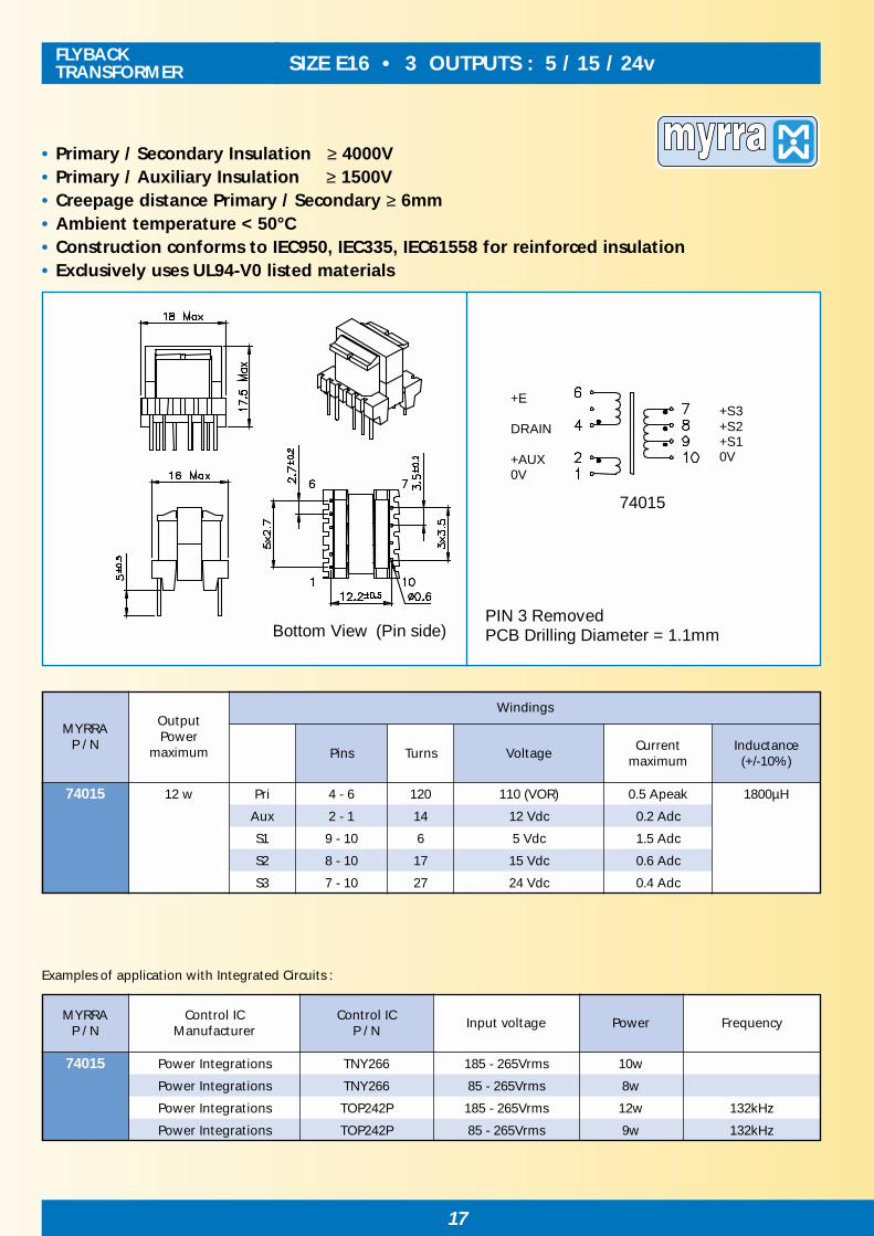
SIZE E16 • 3 OUTPUTS : 5 / 15 / 24vFLYBACKTRANSFORMER
• Primary / Secondary Insulation ≥ 4000V• Primary / Auxiliary Insulation ≥ 1500V• Creepage distance Primary / Secondary ≥ 6mm• Ambient temperature < 50°C• Construction conforms to IEC950, IEC335, IEC61558 for reinforced insulation • Exclusively uses UL94-V0 listed materials
PIN 3 Removed PCB Drilling Diameter = 1.1mm
+S3 +S2 +S1 0V
+E DRAIN +AUX 0V
Bottom View (Pin side)
74015
Examples of application with Integrated Circuits :
74015 12 w Pri 4 - 6 120 110 (VOR) 0.5 Apeak 1800µH
Aux 2 - 1 14 12 Vdc 0.2 Adc
S1 9 - 10 6 5 Vdc 1.5 Adc
S2 8 - 10 17 15 Vdc 0.6 Adc
S3 7 - 10 27 24 Vdc 0.4 Adc
MYRRAP / N
WindingsOutputPower
maximum Pins Turns VoltageCurrent
maximumInductance(+/-10%)
74015 Power Integrations TNY266 185 - 265Vrms 10w
Power Integrations TNY266 85 - 265Vrms 8w
Power Integrations TOP242P 185 - 265Vrms 12w 132kHz
Power Integrations TOP242P 85 - 265Vrms 9w 132kHz
MYRRAP / N
FrequencyControl IC
ManufacturerControl IC
P / NInput voltage Power

18
• Primary / Secondary Insulation ≥ 4000V• Primary / Auxiliary Insulation ≥ 1500V• Creepage distance Primary / Secondary ≥ 6mm• Ambient temperature < 50°C• Construction conforms to IEC950, IEC335, IEC61558 for reinforced insulation • Exclusively uses UL94-V0 listed materials
E
DRAIN
+ AUX0V
+S2 0V +S1 0V
Bottom View (Pin side)
74020 / 74021
PCB Drilling Diameter = 1.1mm
Examples of application with Integrated Circuits :
SIZE EL19 • 2 OUTPUTS : 5 & 12v FLYBACKTRANSFORMER
74020 18 w Pri 4 - 6 108 65 – 130 (VOR) 0.8 Apeak 1250µH
Aux 2 - 1 12 7 – 14 Vdc 0.1 Adc
S1 9 - 10 6 3.3 – 7 Vdc 3 Adc
S2 7 - 8 14 8 – 16.5 Vdc 1.4 Adc
74021 18 w Pri 4 - 6 108 65 – 130 (VOR) 1.1 Apeak 900µH
Aux 2 - 1 12 7 – 14 Vdc 0.1 Adc
S1 9 - 10 6 3.3 – 7 Vdc 3 Adc
S2 7 - 8 14 8 – 16.5 Vdc 1.4 Adc
MYRRAP / N
OutputPower
maximum
Windings
Pins Turns VoltageCurrent
maximumInductance(+/-10%)
MYRRAP / N
FrequencyControl IC
ManufacturerControl IC
P / NInput voltage Power
74020 Power Integrations TNY268 85 - 265Vrms 15w 132kHz
Power Integrations TOP243P 185 - 265Vrms 18w 132kHz
Power Integrations TOP243P 85 - 265Vrms 12w 132kHz
ST Microelectronics VIPer20 85 - 265Vrms 10w 100kHz
ST Microelectronics VIPer20 185 - 265Vrms 12w 100kHz
ST Microelectronics VIPer50 185 - 265Vrms 16w 100kHz
Motorola MC33370 185 - 265Vrms 16w 100kHz
Infineon TDA16832 185 - 265Vrms 16w 100kHz
74021 ST Microelectronics VIPer50 85 - 265Vrms 13w 70kHz
Motorola MC33370 85 - 265Vrms 13w 100kHz
Infineon TDA16831 92 - 265Vrms 10w 100kHz

19
SIZE EL19 • 5 OUTPUTS : 3.3 / 5 / 12 / 18 / 30v FLYBACKTRANSFORMER
• Primary / Secondary Insulation ≥ 4000V• Primary / Auxiliary Insulation ≥ 1500V• Creepage distance Primary / Secondary ≥ 6mm• Ambient temperature < 60°C• Construction conforms to IEC950, IEC335, IEC61558 for reinforced insulation • Exclusively uses UL94-V0 listed materials
Bottom View (Pin side)
E 10 DRAIN 9 +Aux 8 0v 7
1 +S5
2 +S4
3 +S3
4 +S2
5 +S1
6 0V
PCB Drilling Diameter = 1.1mm
74023
Examples of application with Integrated Circuits :
MYRRAP / N
FrequencyControl IC
ManufacturerControl IC
P / NInput voltage Power
74023 Power Integrations TOP243P 185 - 265Vrms 16w 132kHz
Power Integrations TOP243P 85 - 265Vrms 12w 132kHz
74023 16 w Pri 9 – 10 120 110 (VOR) 0.85 Apeak 1250µH
Aux 8 – 7 17 15 Vdc 0.2 Adc
S1 5 – 6 4 3.3 Vdc 2 Adc
S2 4 – 6 6 5 Vdc Sum S1+S2
S3 3 – 6 14 12 Vdc 0.8 Adc
S4 2 – 6 20 18 Vdc 0.8 Adc
S5 1 – 6 33 30 Vdc 0.2 Adc
MYRRAP / N
WindingsOutputPower
maximum Pins Turns VoltageCurrent
maximumInductance(+/-10%)

20
Note for 74080 and 74082 : S1 and S2 can be connected in series or in parallel
• Primary / Secondary Insulation ≥ 4000V • Primary / Auxiliary Insulation ≥ 1500V• Creepage distance Primary / Secondary ≥ 8mm• Ambient temperature < 50°C• Construction conforms to IEC950, IEC335, IEC61558 for reinforced insulation • Exclusively uses UL94-V0 listed materials
PIN 3 Removed PCB Drilling Diameter = 1.2mmBottom View (Pin side)
+S2 +S1 0V +S3 0V
+E DRAIN+AUX 0V
+E DRAIN+AUX 0V
+S1 0V +S2 0V
74080 - 74082
74081
SIZE EF20 • 2 or 3 OUTPUTS : 5/5v or 12/12v or 3.3+5/12v FLYBACKTRANSFORMER
Examples of application with Integrated Circuits :
74080 24 w Pri 4 – 5 86 80 – 135 (VOR) 1.0 Apeak 1000µH
Aux 2 – 1 12 11 - 18 Vdc 0.3 Adc
S1 6 – 7 10 9 – 15 Vdc 1.5 Adc
S2 9 – 10 10 9 – 15 Vdc 1.5 Adc
74081 20 w Pri 4 – 5 80 75 (VOR) 0.9 Apeak 1100µH
Aux 2 – 1 17 15 Vdc 0.3 Adc
S1 7 – 8 4 3.3 Vdc 3 Adc
S2 6 – 8 6 5 Vdc Sum S1+S2
S3 9 – 10 14 12 Vdc 1.3 Adc
74082 20 w Pri 4 – 5 86 60 – 135 (VOR) 0.85 Apeak 1300µH
Aux 2 – 1 12 7 - 18 Vdc 0.3 Adc
S1 6 – 7 5 3 – 7.5 Vdc 2.0 Adc
S2 9 – 10 5 3 – 7.5 Vdc 2.0 Adc
MYRRAP / N
WindingsOutputPower
maximum Pins Turns VoltageCurrent
maximumInductance(+/-10%)
74080 Power Integrations TOP243P 185 - 265Vrms 24w 132kHz
Power Integrations TOP243P 85 - 265Vrms 15w 132kHz
74081 Power Integrations TOP243P 185 - 265Vrms 20w 132kHz
Power Integrations TOP243P 85 – 265Vrms 12w 132kHz
74082 Power Integrations TOP243P 185 - 265Vrms 20w 132kHz
Power Integrations TOP243P 85 – 265Vrms 14w 132kHz
Power Integrations TNY268 185 - 265Vrms 17w < 120kHz
MYRRAP / N
FrequencyControl IC
ManufacturerControl IC
P / NInput voltage Power

21
• Primary / Secondary Insulation ≥ 4000V• Primary / Auxiliary Insulation ≥ 1500V• Creepage distance Primary / Secondary ≥ 6mm• Ambient temperature < 50°C• Construction conforms to IEC950, IEC335, IEC61558 for reinforced insulation • Exclusively uses UL94-V0 listed materials
PIN 4 Removed PCB Drilling Diameter = 1.4mm
Bottom View (Pin side)
+S1 0V
+E DRAIN+AUX 0V
+E DRAIN+AUX 0V
+S2 +S1 0V +S3 0V
74030
74032
Examples of application with Integrated Circuits :
SIZE E25 • 3 or 1 OUTPUTS : 5+12/12v or 24v FLYBACKTRANSFORMER
Note for 74030 : S2 and S3 can be connected in series or in parallel
MYRRAP / N
OutputPower
maximum
Windings
Pins Turns VoltageCurrent
maximumInductance(+/-10%)
74030 30 w Pri 3 – 5 70 65 – 130 (VOR) 1.5 Apeak 750µH
Aux 2 – 1 8 7 – 14.5 Vdc 1 Adc
S1 7 – 8 4 3.3 - 7 3 Adc
S2 6 – 8 9 8 – 16 Vdc 1.5 Adc
S3 9 – 10 9 8 – 16 Vdc 1.5 Adc
74032 35 w Pri 3 – 5 72 62 - 125 (VOR) 1.1 Apeak 1100µH
Aux 2 – 1 10 8 - 16 Vdc 1 Adc
S1 6 – 10 18 15 - 30 Vdc 1.4 Adc
MYRRAP / N
FrequencyControl IC
ManufacturerControl IC
P / NInput voltage Power
74030 Power Integrations TOP244P 185 - 265Vrms 30w 132kHz
Power Integrations TOP244Y 85 - 265Vrms 25w 66 or 132kHz
ST Microelectronics VIPer50 85 - 265Vrms 22w 70kHz
ST Microelectronics VIPer50 185 - 265Vrms 30w 70kHz
Motorola MC33371 85 - 265Vrms 22w 100kHz
Motorola MC33371 185 - 265Vrms 30w 100kHz
Infineon TDA16832 185 - 265Vrms 30w 100kHz
Fairchild KA1H0265R 85 - 265Vrms 22w 100kHz
74032 Power Integrations TOP244P 185 - 265Vrms 25w 132kHz

22
SIZE ETD29 • 4 OUTPUTS : 5+12 / 5+12vFLYBACKTRANSFORMER
• Primary / Secondary Insulation ≥ 4000V• Primary / Auxiliary Insulation ≥ 1500V• Creepage distance Primary / Secondary ≥ 8mm• Ambient temperature < 50°C• Construction conforms to IEC950, IEC335, IEC61558 for reinforced insulation • Exclusively uses UL94-V0 listed materials
PIN 4 Removed PCB Drilling Diameter = 1.3mmBottom View
(Pin side)
+E DRAIN +AUX 0V
+S4 +S3 0V +S2 +S1 0V
Examples of application with Integrated Circuits :
74040 60 w Pri 5 – 7 50 60 – 125 (VOR) 3.0 Apeak 500µH
Aux 3 – 2 6 7 – 14.5 Vdc 0.5 Adc
S1 12 – 13 3 3.3 - 7 4 Adc
S2 11 – 13 7 8 – 16.5 Vdc 2.5 Adc
S3 9 – 10 3 3.3 - 7 4 Adc
S4 8 - 10 7 8 – 16.5 Vdc 2.5 Adc
MYRRAP / N
WindingsOutputPower
maximum Pins Turns VoltageCurrent
maximumInductance(+/-10%)
Note : S1 / S3 or S2 / S4 can be connected in series or in parallel
MYRRAP / N
FrequencyControl IC
ManufacturerControl IC
P / NInput voltage Power
74040 Power Integrations TOP245Y 185 - 265Vrms 60w 66 or 132kHz
Power Integrations TOP245Y 85 - 265Vrms 45w 66 or 132kHz
ST Microelectronics VIPer50 85 - 265Vrms 35w 100kHz
ST Microelectronics VIPer50 185 - 265Vrms 45w 100kHz
Motorola MC33372 85 - 265Vrms 35w 100kHz
Motorola MC33372 185 - 265Vrms 45w 100kHz
Infineon TDA16834 92 - 265Vrms 35w 100kHz
Infineon TDA16834 185 - 265Vrms 45w 100kHz

23
MYRRAP / N
OutputPower
maximum
Windings
Pins Turns VoltageCurrent
maximumInductance(+/-10%)
74043 60w Pri 5 – 1 45 90 (VOR) 3 Apeak 500µH
Aux 8 – 9 7 15 Vdc 0.5 Adc
S1 14+15 / 12+13 2 3.3 Vdc 7 Adc
S2 11 / 12+13 3 5 Vdc Sum S1+S2
S3 16 – 10 4 12 Vdc 2 Adc
S4 17 – 10 7 18 Vdc 2 Adc
S5 18 – 10 13 30 Vdc 0.5 Adc
• Primary / Secondary Insulation ≥ 4000V• Primary / Auxiliary Insulation ≥ 1500V• Creepage distance Primary / Secondary ≥ 6mm• Ambient temperature < 50°C• Construction conforms to IEC950, IEC335, IEC61558 for reinforced insulation • Exclusively uses UL94-V0 listed materials
Bottom View (Pin side)
PCB Drilling Diameter = 1.3mm
E 1 DRAIN 5 +Aux 8 0v 9
18 +30v
17 +18v
16 +12v
10 +5v(dc)
11 +5v(ac)
14,15 +3v3
12,13 0v
Examples of application with Integrated Circuits :
SIZE ERL28 • 5 OUTPUTS : 3.3 / 5 / 12 / 18 / 30v FLYBACKTRANSFORMER
MYRRAP / N
FrequencyControl IC
ManufacturerControl IC
P / NInput voltage Power
74043 Power Integrations TOP246Y 185 - 265Vrms 60w 66 or 132kHz
Power Integrations TOP246Y 85 - 265Vrms 45w 66 or 132kHz

24
SIZE ETD34 • 4 OUTPUTS : 5+12 / 5+12vFLYBACKTRANSFORMER
• Primary / Secondary Insulation ≥ 4000V• Primary / Auxiliary Insulation ≥ 1500V• Creepage distance Primary / Secondary ≥ 8mm• Ambient temperature < 50°C• Construction conforms to IEC950, IEC335, IEC61558 for reinforced insulation • Exclusively uses UL94-V0 listed materials
PIN 4 Removed PCB Drilling Diameter = 1.5mmBottom View
(Pin side)
+E DRAIN +AUX 0V
+S4 +S3 0V +S2 +S1 0V
Examples of application with Integrated Circuits :
Note : S1 / S3 or S2 / S4 can be connected in series or in parallel
74050 90 w Pri 5 – 7 36 65 – 125 (VOR) 2.8 Apeak 500µH
Aux 3 – 2 4 7 – 14 Vdc 0.5 Adc
S1 12 – 13 2 3.3 – 6.5 5 Adc
S2 11 – 13 5 8.5 – 17 Vdc 3 Adc
S3 9 – 10 2 3.3 – 6.5 5 Adc
S4 8 - 10 5 8.5 – 17 Vdc 3 Adc
MYRRAP / N
WindingsOutputPower
maximum Pins Turns VoltageCurrent
maximumInductance(+/-10%)
74050 Power Integrations TOP246Y 185 - 265Vrms 90w 132kHz
Power Integrations TOP246Y 85 - 265Vrms 60w 66 or 132kHz
ST Microelectronics VIPer100A 185 - 265Vrms 80w 70kHz
ST Microelectronics VIPer100A 85 - 265Vrms 60w 70kHz
Motorola MC33373 185 - 265Vrms 80w 100kHz
Motorola MC33373 85 - 265Vrms 60w 100kHz
Infineon TDA16834 185 - 265Vrms 80w 100kHz
Infineon TDA16836 85 - 265Vrms 60w 100kHz
MYRRAP / N
FrequencyControl IC
ManufacturerControl IC
P / NInput voltage Power
25
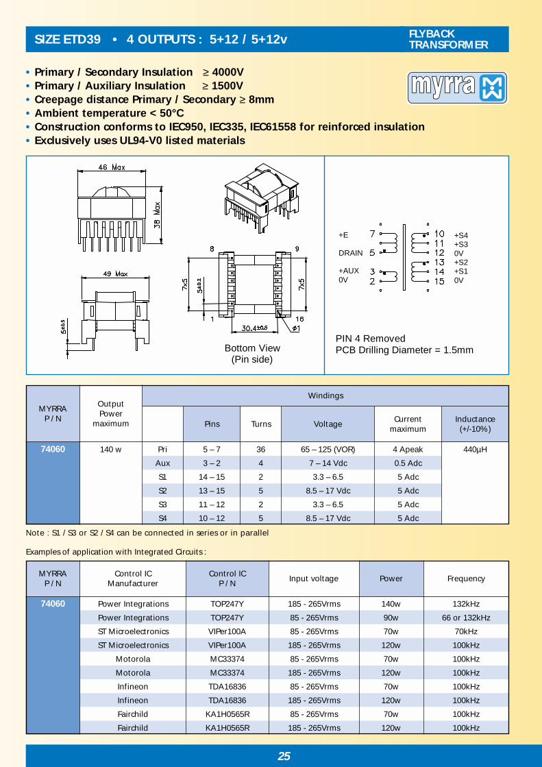
Note : S1 / S3 or S2 / S4 can be connected in series or in parallel
Examples of application with Integrated Circuits :
• Primary / Secondary Insulation ≥ 4000V• Primary / Auxiliary Insulation ≥ 1500V• Creepage distance Primary / Secondary ≥ 8mm• Ambient temperature < 50°C• Construction conforms to IEC950, IEC335, IEC61558 for reinforced insulation • Exclusively uses UL94-V0 listed materials
PIN 4 Removed PCB Drilling Diameter = 1.5mmBottom View
(Pin side)
+E DRAIN +AUX 0V
+S4 +S3 0V +S2 +S1 0V
SIZE ETD39 • 4 OUTPUTS : 5+12 / 5+12v FLYBACKTRANSFORMER
74060 140 w Pri 5 – 7 36 65 – 125 (VOR) 4 Apeak 440µH
Aux 3 – 2 4 7 – 14 Vdc 0.5 Adc
S1 14 – 15 2 3.3 – 6.5 5 Adc
S2 13 – 15 5 8.5 – 17 Vdc 5 Adc
S3 11 – 12 2 3.3 – 6.5 5 Adc
S4 10 – 12 5 8.5 – 17 Vdc 5 Adc
MYRRAP / N
WindingsOutputPower
maximum Pins Turns VoltageCurrent
maximumInductance(+/-10%)
74060 Power Integrations TOP247Y 185 - 265Vrms 140w 132kHz
Power Integrations TOP247Y 85 - 265Vrms 90w 66 or 132kHz
ST Microelectronics VIPer100A 85 - 265Vrms 70w 70kHz
ST Microelectronics VIPer100A 185 - 265Vrms 120w 100kHz
Motorola MC33374 85 - 265Vrms 70w 100kHz
Motorola MC33374 185 - 265Vrms 120w 100kHz
Infineon TDA16836 85 - 265Vrms 70w 100kHz
Infineon TDA16836 185 - 265Vrms 120w 100kHz
Fairchild KA1H0565R 85 - 265Vrms 70w 100kHz
Fairchild KA1H0565R 185 - 265Vrms 120w 100kHz
MYRRAP / N
FrequencyControl IC
ManufacturerControl IC
P / NInput voltage Power
Examples of application with Integrated Circuits :

26
SIZE ETD44 • 4 OUTPUTS : 5+12 / 5+12v FLYBACKTRANSFORMER
• Primary / Secondary Insulation ≥ 4000V• Primary / Auxiliary Insulation ≥ 1500V• Creepage distance Primary / Secondary ≥ 8mm• Ambient temperature < 50°C• Construction conforms to IEC950, IEC335, IEC61558 for reinforced insulation • Exclusively uses UL94-V0 listed materials
PIN 4 Removed PCB Drilling Diameter = 1.5mmBottom View
(Pin side)
+E DRAIN +AUX 0V
+S4 +S3 0V +S2 +S1 0V
Examples of application with Integrated Circuits :
Note : S1 / S3 or S2 / S4 can be connected in series or in parallel
74070 180 w Pri 5 – 7 38 65 – 125 (VOR) 8 Apeak 300µH
Aux 3 – 2 4 7 – 14 Vdc 0.5 Adc
S1 16 – 17 2 3.3 – 6.5 6 Adc
S2 15 – 17 5 8.5 – 17 Vdc 5 Adc
S3 13 – 14 2 3.3 – 6.5 6 Adc
S4 12 – 14 5 8.5 – 17 Vdc 5 Adc
MYRRAP / N
WindingsOutputPower
maximum Pins Turns VoltageCurrent
maximumInductance(+/-10%)
74070Power Integrations
TOP248Y185 - 265Vrms 180w 66 or 132kHz
TOP249Y
Power Integrations TOP249Y 85 - 265Vrms 120w 66kHz
Infineon TDA16837 185 - 265Vrms 160w 100kHz
Fairchild KA2S0965 185 - 265Vrms 160w 100kHz
Philips TEA1566 185 - 265Vrms 120w 50kHz
MYRRAP / N
FrequencyControl IC
ManufacturerControl IC
P / NInput voltage Power

27
COMMON MODE CHOKES RANGEFOR EMI SUPPRESSION
• Mainly used to reduce noise conducted through power or signal lines.
• The common mode inductance filters symmetrical noise, associated with Y-typesafety capacitors connected to ground.
• The differential mode inductance filters asymmetrical noise, associated with X-type capacitor connected between Line and Neutral.
74330 - 74335 U9.8 1.5 to 47mH 0.18 to 1.1A
74300 - 74306 U10.5 1.5 to 68mH 0.30 to 1.9A
74310 - 74315 U16 1.5 to 33mH 0.75 to 3.3A
74320 - 74325 E25 1.5 to 33mH 0.90 to 4.0A
Inductance rangeMYRRAPart N°
Current rangeSIZE
U9.8 U10.5 U16 E25

28
COMMON MODE CHOKES FOR EMI SUPPRESSION
• Ambient Temperature ≤ 50°C• Dielectric Strength ≥ 1.5 kV between windings• Electrical characteristics at 25 °C
SIZE : U9.8
ELECTRICAL CHARACTERISTICS :
View from pin side PCB Drilling diameter 1.0 mm
MECHANICAL CHARACTERISTICS / PINOUT :
74330 33 - 56 0.18 7 710 210
74331 18 - 31 0.26 3.5 360 280
74332 10 - 17 0.35 2.0 210 400
74333 4.7 - 8 0.5 .95 100 610
74334 2.2 - 3.7 0.8 .4 45 910
74335 1 - 1.7 1.1 .21 20 1300
MYRRAInductance Rated Resistance Inductance Resonant
Part N°Common Mode Current per winding Differential Mode Frequencymin - max (mH) Arms ohm max µH min kHz min
29
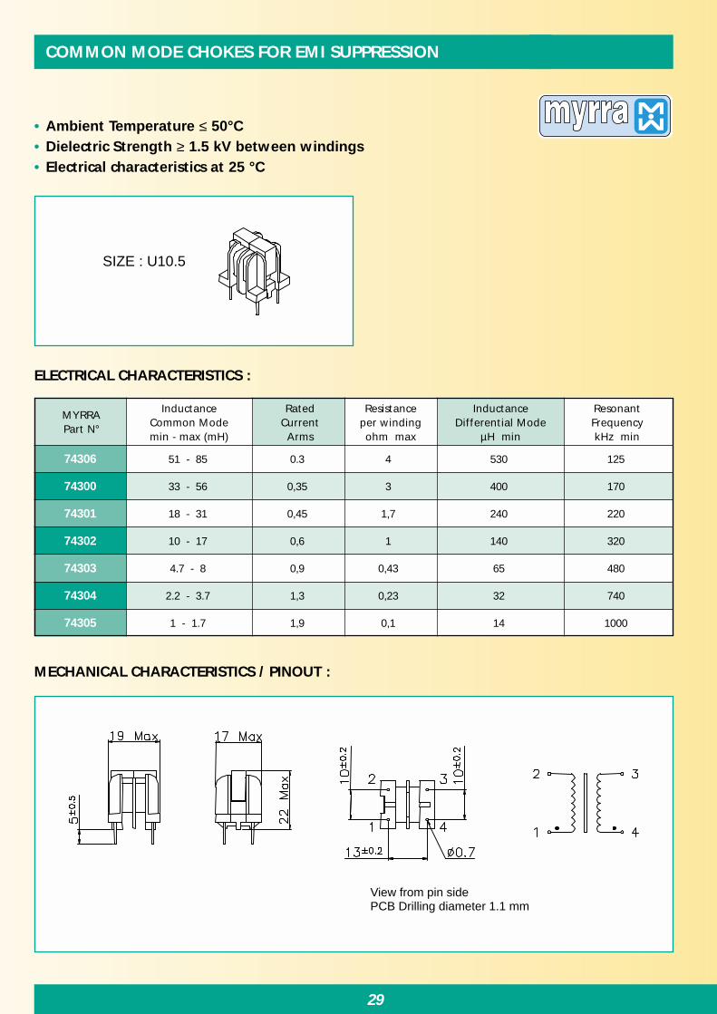
MECHANICAL CHARACTERISTICS / PINOUT :
• Ambient Temperature ≤ 50°C• Dielectric Strength ≥ 1.5 kV between windings• Electrical characteristics at 25 °C
SIZE : U10.5
ELECTRICAL CHARACTERISTICS :
View from pin side PCB Drilling diameter 1.1 mm
COMMON MODE CHOKES FOR EMI SUPPRESSION
74306 51 - 85 0.3 4 530 125
74300 33 - 56 0,35 3 400 170
74301 18 - 31 0,45 1,7 240 220
74302 10 - 17 0,6 1 140 320
74303 4.7 - 8 0,9 0,43 65 480
74304 2.2 - 3.7 1,3 0,23 32 740
74305 1 - 1.7 1,9 0,1 14 1000
MYRRAInductance Rated Resistance Inductance Resonant
Part N°Common Mode Current per winding Differential Mode Frequencymin - max (mH) Arms ohm max µH min kHz min

30
COMMON MODE CHOKES FOR EMI SUPPRESSION
• Ambient Temperature ≤ 50°C• Dielectric Strength ≥ 1.5 kV between windings• Electrical characteristics at 25 °C
SIZE : U16
ELECTRICAL CHARACTERISTICS :
View from pin side PCB Drilling diameter 1.1 mm
MECHANICAL CHARACTERISTICS / PINOUT :
MYRRAInductance Rated Resistance Inductance Resonant
Part N°Common Mode Current per winding Differential Mode Frequencymin - max (mH) Arms ohm max µH min kHz min
74310 22 – 37 0,75 1 230 170
74311 15 – 25 0,9 0,75 150 210
74312 10 - 17 1,1 0,44 100 280
74313 4.7 - 8 1,5 0,24 50 440
74314 2.2 - 3.7 2,3 0,095 20 650
74315 1 - 1.7 3,3 0,046 10 1000

31
MECHANICAL CHARACTERISTICS / PINOUT :
• Ambient Temperature ≤ 50°C• Dielectric Strength ≥ 1.5 kV between windings• Electrical characteristics at 25 °C
SIZE : E25
ELECTRICAL CHARACTERISTICS :
View from pin side PCB Drilling diameter 1.2 mm
COMMON MODE CHOKES FOR EMI SUPPRESSION
74320 22 – 37 0,9 0,54 130 170
74321 15 – 25 1,1 0,35 90 210
74322 10 - 17 1,3 0,22 50 270
74323 4.7 - 8 1,8 0,105 25 400
74324 2.2 - 3.7 2,7 0,05 11 630
74325 1 - 1.7 4 0,03 7 950
MYRRAInductance Rated Resistance Inductance Resonant
Part N°Common Mode Current per winding Differential Mode Frequencymin - max (mH) Arms ohm max µH min kHz min

32
DIMMER CHOKES FOR EMI SUPPRESSION
• For noise suppression in light dimmers• Saturable chokes : provides a high impedance for Triac switching
interferences, and a low impedance for 50Hz component.• Electrical characteristics at 25 °
ELECTRICAL CHARACTERISTICS :
L = 25 +/-10mm
MECHANICAL CHARACTERISTICS :
74190 150 w 3.5 mH 0.7 Arms 1.5 Ω 22 nF 24 9 9.5 0.5 13 g
74191 300 w 2.8 mH 1.3 Arms 0.73 Ω 47 nF 29 10 11 0.7 24 g
74192 500 w 2.0 mH 2.2 Arms 0.35 Ω 82 nF 32.5 9 16 0.9 47 g
74196 500 w 1.8 mH 2.2 Arms 0.37 Ω 82 nF 38 14 12 0.9 39 g
74193 1000 w 1.3 mH 4.5 Arms 0.15 Ω 220 nF 44 14 16.5 1.2 80 g
74194 2200 w 450 µH 10 Arms 0.04 Ω 470 nF 50 15 22.5 1.8 140 g
74195 4500 w 250 µH 20 Arms 0.014 Ω 1 µF 58 15 27 2.5 250 g
Power
Dimensions (mm)
MYRRAPart N°
Inductance+/- 15 %
RatedCurrent
ResistanceAssociatedCapacitor OD
maxODmin
Hmax
Wmax
Approx.Weight

33
• For use as filtering or DC/DC power conversion.• Electrical characteristics given for 25 °C• Ambient temperature up to 70°C without derating• Models 74460 & 74461 are designed to make a non-isolated supply in association
with Power Integrations TinySwitch integrated circuits.
ELECTRICAL CHARACTERISTICS :
1 2
11 max
5.0 20 +/-5
15 +/-5
16 max
0.9 max
DRUM CORE CHOKES
MECHANICAL CHARACTERISTICS :
74450 10 µH 5.0 Arms 6.5 Apeak 0.016 Ω
74451 22 µH 3.5 Arms 4.2 Apeak 0.031 Ω
74452 47 µH 2.4 Arms 2.9 Apeak 0.07 Ω
74453 100 µH 1.5 Arms 2.0 Apeak 0.15 Ω
74454 220 µH 1.1 Arms 1.35 Apeak 0.30 Ω
74460 470 µH 0.7 Arms 0.95 Apeak 0.70 Ω
74461 820 µH 0.55 Arms 0.7 Apeak 1.15 Ω
MYRRAPart N°
Inductance+/- 10 %
RatedCurrent
SaturationCurrent
Resistancemax

34
CURRENT TRANSFORMERS RANGE
• FOR MAINS AC CURRENT MEASUREMENT - 50 to 400 Hz
E13 E19-V E19-H E25
T40 U10.5 T15 T18 T30
• FOR SWITCH MODE POWER SUPPLIES - 20 to 150kHz
PIN PRIMARY - up to 25A
74521 Size E19-H Ratio 1 / 1 / 750 Current 10 A / 20 A
74523 Size E19-V Ratio 1 / 500 Current 15 A
74531 Size E25 Ratio 1 / 1 / 1000 Current 12.5 A / 25 A
74533 Size E25 Ratio 1 / 1000 Current 8 A
74534 Size E25 Ratio 1 / 350 Current 4 A
74561 Size U10.5 Ratio 1 / 2000 Current 8 A
THRU-HOLE PRIMARY - up to 250A
74503 Size T18 Ratio 1 / 1000 Current 12 A
74504 Size T18 Ratio 1 / 750 Current 10 A
74511 Size T30 Ratio 1 / 1000 Current 60 A
74543, 74544, 74545 Size T40 Ratio 1 / 500 Current 100 A
74546, 74547, 74548 Size T40 Ratio 1 / 1000 Current 250 A
RatioMYRRAPart N°
Current rangeSIZE
RatioMYRRAPart N°
Current rangeSIZE
PIN PRIMARY - up to 25A
74520 Size E19-H Ratio 1 / 1 / 100 Current 10 A/ 20 A
74530 Size E25 Ratio 1 / 1 / 100 Current 12.5 A/ 25 A
74550 Size E13 Ratio 1 / 100 Current 10 A
74560 Size U10.5 Ratio 1 / 100 Current 10 A
74562 Size U10.5 Ratio 1 / 100 Current 10 A
74570 Size T15 Ratio 1 / 1 / 50 Current 10 A/ 20 A
THRU-HOLE PRIMARY - up to 200A
74500 Size T18 Ratio 1 / 50 Current 15 A
74501 Size T18 Ratio 1 / 100 Current 25 A
74502 Size T18 Ratio 1 / 200 Current 25 A
74510 Size T30 Ratio 1 / 100 Current 150 A
74540, 74541, 74542 Size T40 Ratio 1 / 100 Current 200 A
35
18 max
12.7
10 max
3 1
21 max
3 1
HOLE DIA 5
Primary Current Direction
P
3 S 1
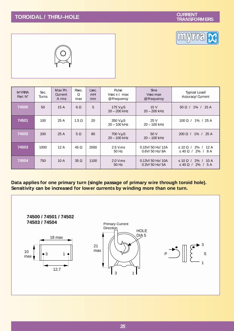
74500 / 74501 / 74502 74503 / 74504
TOROIDAL / THRU–HOLE CURRENTTRANSFORMERS
Data applies for one primary turn (single passage of primary wire through toroid hole).Sensitivity can be increased for lower currents by winding more than one turn.
74500 50 15 A 6 Ω 5 175 V.µS 15 V 50 Ω / 1% / 15 A20 – 200 kHz 20 – 200 kHz
74501 100 25 A 1.5 Ω 20 350 V.µS 25 V 100 Ω / 1% / 25 A20 – 100 kHz 20 – 100 kHz
74502 200 25 A 5 Ω 80 700 V.µS 50 V 200 Ω / 1% / 25 A20 – 100 kHz 20 – 100 kHz
74503 1000 12 A 45 Ω 2000 2.5 V.ms 0.15V/ 50 Hz/ 12A ≤ 10 Ω / 2% / 12 A50 Hz 0.6V/ 50 Hz/ 8A ≤ 40 Ω / 2% / 8 A
74504 750 10 A 35 Ω 1100 2.0 V.ms 0.13V/ 50 Hz/ 10A ≤ 10 Ω / 2% / 10 A50 Hz 0.3V/ 50 Hz/ 5A ≤ 40 Ω / 2% / 5 A
MYRRAPart N°
Typical Load/Accuracy/ Current
Sec.Turns
Max Pri.CurrentA rms
PulseVsec x t max@ Frequency
SineVsec max
@ Frequency
Rsec.Ω
max
Lsec.mHmin

36
74510/ 74511
P
7 S 2
Pin 8 removed for locating
Primary currentdirection
6 10
TOROIDAL / THRU–HOLECURRENTTRANSFORMERS
Data applies for one primary turn (single passage of primary wire through toroid hole).Sensitivity can be increased for lower currents by winding more than one turn.Models with 50, 100, 200 turns are designed for switch-mode power conversion(up to 200 kHz).Models with 500 and 1000 turns are designed for Mains current measurement (50 to 400 Hz).
74510 100 150 A 0.25Ω 401 V.ms/ 20 kHz
50 V/ 20 kHz700 V µs/80 V/ 100 kHz
1 - 20 Ω / 1%100 kHz
74511 1000 60 A 32 Ω 4000 10 V.ms/ 50 Hz 0.6 V/ 50 Hz/ 60 A ≤ 10 Ω / 1% / 60 A1 V/ 50 Hz/ 40 A ≤ 20 Ω / 1% / 40 A
MYRRAPart N°
Typical Load/Accuracy/ Current
Sec.Turns
Max Pri.CurrentA rms
PulseVsec x t max@ Frequency
SineVsec max
@ Frequency
Rsec.Ω
max
Lsec.mHmin

37
1 P1 4 2 P2 3
8 S 5
74520/ 74521
Pins 6 & 7 removed for locating
PIN PRIMARY TYPES CURRENTTRANSFORMERS
SAFETY :These products are only composed of UL approved materials.These products have a construction conform to CEI950, CEI335, CEI61558 for Basic insulation(3 mm creepage distance)
74521 1/1/750 20 A parallel10 A serie 57 300 15 V.ms 3 Vrms ≤ 75 Ω / 4% / 20 A 2500 V
74520 1/1/100 20 A parallel 1.5 8 400 V.µs 50 Vrms 10 – 100 Ω / 1% / 10 A 2500 V10 A serie
MYRRAPart N°
Typical Load/Accuracy/ Current
InsulationVoltage
P/ SRatio
Max Pri.CurrentA rms
PulseVsec x t
max
SineVsec
rms max
Rsec.Ω
max
Lsec.mHmin
FOR SWITCH MODE POWER SUPPLIES - 20 to 150 kHz
MYRRAPart N°
Typical Load/Accuracy/ Current
InsulationVoltage
P/ SRatio
Max Pri.CurrentA rms
PulseVsec x t
max
SineVsec
rms max
Rsec.Ω
max
Lsec.mHmin
FOR MAINS AC CURRENT MEASUREMENT - 50 to 400 Hz

38
1 P 2
4 S 3
74523
Pins 6 & 7 removed for locating
PIN PRIMARY TYPESCURRENTTRANSFORMERS
SAFETY :This product is only composed of UL approved materials.This product has a construction conform to CEI950, CEI335, CEI61558 for Functional insulation
74523 1/ 500 15 A 155 670 30 V.ms 6 Vrms ≤ 50 Ω / 2% / 15 A 1500 V≤ 200 Ω / 5% / 10 A
MYRRAPart N°
Typical Load/Accuracy/ Current
InsulationVoltage
P/ SRatio
Max Pri.CurrentA rms
PulseVsec x t
max
SineVsec
rms max
Rsec.Ω
max
Lsec.mHmin
FOR MAINS AC CURRENT MEASUREMENT - 50 to 400 Hz

39
9 P 7
2 S 4
10 P1 6 9 P2 7
2 S 4
Pins 1 & 8 removed for locating
74530/ 74531
74533/ 74534
PIN PRIMARY TYPES CURRENTTRANSFORMERS
SAFETY :These products are only composed of UL approved materials.These products have a construction conform to CEI950, CEI335, CEI61558 for Basic insulation(3 mm creepage distance)
74531 1/1/1000 25 A parallel 90 4 H 8 V.ms 1.6 Vrms ≤ 50 Ω / 2% / 20 A 2500 V 12.5 A serie
74533 1/ 1000 8 A 360 17 H 15 V.ms 3 Vrms ≤ 200 Ω / 1% / 8 A 2500 V≤ 500 Ω / 1.5% / 5 A
74534 1/ 350 4 A 380 19 H 15 V.ms 3 Vrms ≤ 100 Ω / 1% / 4 A 2500 V≤ 500 Ω / 1% / 2 A
74530 1/1/100 25 A parallel 1 10 600 V.µs 80 Vrms 10 - 100 Ω/ 1%/ 25 A 2500 V12.5 A serie
MYRRAPart N°
Typical Load/Accuracy/ Current
InsulationVoltage
P/ SRatio
Max Pri.CurrentA rms
PulseVsec x t
max
SineVsec
rms max
Rsec.Ω
max
Lsec.mHmin
FOR SWITCH MODE POWER SUPPLIES - 20 to 150 kHz
MYRRAPart N°
Typical Load/Accuracy/ Current
InsulationVoltage
P/ SRatio
Max Pri.CurrentA rms
PulseVsec x t
max
SineVsec
rms max
Rsec.Ω
max
Lsec.mHmin
FOR MAINS AC CURRENT MEASUREMENT - 50 to 400 Hz

40
74540/ 74543/ 74546 Pin type (for PCB)
Primary Current Direction
P
2 S 1
TOROIDAL / THRU–HOLECURRENTTRANSFORMERS
Data applies for one primary turn (single passage of primary wire through toroid hole).Sensitivity can be increased for lower currents by winding more than one turn.
74546 1000 250 A 22 Ω 8000 100 V.ms/ 50 Hz 15 V/ 50 Hz/ 250 A ≤ 50 Ω / 1% / 250 A
74540 100 200 A 0.35Ω 50 2 V.ms/ 20 kHz 150 V/ 20 kHz 1..20 Ω / 1%1 V.ms/ 100 kHz 150 V/ 100 kHz
74543 500 100 A 6.5 Ω 1250 10 V.ms/ 50 Hz 0.7 V/ 50Hz/ 100 A ≤ 3 Ω / 1% / 100 A1.2 V/ 50Hz/ 60 A ≤ 10 Ω / 1% / 60 A
MYRRAPart N°
Typical Load/Accuracy/ Current
Sec.Turns
Max Pri.CurrentA rms
PulseVsec x t max@ Frequency
SineVsec max
@ Frequency
Rsec.Ω
max
Lsec.mHmin

41
74541/ 74544/ 74547 FASTON Connectors
P
2 S 1
Primary Current Direction
TOROIDAL / THRU–HOLE CURRENTTRANSFORMERS
Data applies for one primary turn (single passage of primary wire through toroid hole).Sensitivity can be increased for lower currents by winding more than one turn.
74547 1000 250 A 22 Ω 8000 100 V.ms/ 50 Hz 15 V/ 50 Hz/ 250 A ≤ 50 Ω / 1% / 250 A
74541 100 200 A 0.35Ω 50 2 V.ms/ 20 kHz 150 V/ 20 kHz 1..20 Ω / 1%1 V.ms/ 100 kHz 150 V/ 100 kHz
74544 500 100 A 6.5 Ω 1250 10 V.ms/ 50 Hz 0.7 V/ 50Hz/ 100 A ≤ 3 Ω / 1% / 100 A1.2 V/ 50Hz/ 60 A ≤ 10 Ω / 1% / 60 A
MYRRAPart N°
Typical Load/Accuracy/ Current
Sec.Turns
Max Pri.CurrentA rms
PulseVsec x t max@ Frequency
SineVsec max
@ Frequency
Rsec.Ω
max
Lsec.mHmin

42
74542/ 74545/ 74548 Wires type
P
2 S 1
Primary current Direction
Wires Length 250 10 mm 1 = Black 0.5 mm2
2 = Red 0.5 mm2
TOROIDAL / THRU–HOLECURRENTTRANSFORMERS
Data applies for one primary turn (single passage of primary wire through toroid hole).Sensitivity can be increased for lower currents by winding more than one turn.
74548 1000 250 A 22 Ω 8000 100 V.ms/ 50 Hz 15 V/ 50 Hz/ 250 A ≤ 50 Ω / 1% / 250 A
74542 100 200 A 0.35Ω 50 2 V.ms/ 20 kHz 150 V/ 20 kHz 1..20 Ω / 1%1 V.ms/ 100 kHz 150 V/ 100 kHz
74545 500 100 A 6.5 Ω 1250 10 V.ms/ 50 Hz 0.7 V/ 50Hz/ 100 A ≤ 3 Ω / 1% / 100 A1.2 V/ 50Hz/ 60 A ≤ 10 Ω / 1% / 60 A
MYRRAPart N°
Typical Load/Accuracy/ Current
Sec.Turns
Max Pri.CurrentA rms
PulseVsec x t max@ Frequency
SineVsec max
@ Frequency
Rsec.Ω
max
Lsec.mHmin

43
1 P 2
4 S 3
74550
PIN PRIMARY TYPES CURRENTTRANSFORMERS
SAFETY :This product is only composed of UL approved materials.This product has a construction conform to CEI950, CEI335, CEI61558 for functional insulation
74550 1/ 100 10 2.3 6 250 V.µs 40 Vrms 10 – 100 Ω / 1% / 10 A 1500 V
MYRRAPart N°
Typical Load/Accuracy/ Current
InsulationVoltage
P/ SRatio
Max Pri.CurrentA rms
PulseVsec x t
max
SineVsec
rms max
Rsec.Ω
max
Lsec.mHmin
FOR SWITCH MODE POWER SUPPLIES - 20 to 150 kHz

44
1 P 2
4 S 3
74560/ 74561
2 P 5
1 S 6
74562
PIN PRIMARY TYPESCURRENTTRANSFORMERS
SAFETY :These products are only composed of UL approved materials.These products have a construction conform to CEI950, CEI335, CEI61558 for Reinforcedinsulation 74560, 74561 : 8 mm creepage distance74562 : 6 mm creepage distance
74560 1/ 100 10 1.1 12 300 V.µs 25 Vrms 5 – 50 Ω / 1% / 10 A 4000 V
74562 1/ 100 25 1.1 12 300 V.µs 25 Vrms 5 – 50 Ω / 1% / 25 A 4000 V
MYRRAPart N°
Typical Load/Accuracy/ Current
InsulationVoltage
P/ SRatio
Max Pri.CurrentA rms
PulseVsec x t
max
SineVsec
rms max
Rsec.Ω
max
Lsec.mHmin
FOR SWITCH MODE POWER SUPPLIES - 20 to 150 kHz
74561 1/ 2000 8 A 400 4.5 H 5 V.ms 1 Vrms ≤ 100 Ω / 2% / 6 A 4000 V
MYRRAPart N°
Typical Load/Accuracy/ Current
InsulationVoltage
P/ SRatio
Max Pri.CurrentA rms
PulseVsec x t
max
SineVsec
rms max
Rsec.Ω
max
Lsec.mHmin
FOR MAINS AC CURRENT MEASUREMENT - 50 to 400 Hz

45
PIN PRIMARY TYPES CURRENTTRANSFORMERS
3 P1 6 4 P2 5
1 S 8
74570
Pins 2 & 7 removed for locating
SAFETY :This product is only composed of UL approved materials.This product has a construction conform to CEI950, CEI335, CEI61558 for Reinforced insulation(8 mm creepage distance)
74570 1/1/50 20 A parallel 0.32 9 150 V.µs 12 Vrms 5 – 25 Ω / 1% / 20 A 4000 V10 A serie
MYRRAPart N°
Typical Load/Accuracy/ Current
InsulationVoltage
P/ SRatio
Max Pri.CurrentA rms
PulseVsec x t
max
SineVsec
rms max
Rsec.Ω
max
Lsec.mHmin
FOR SWITCH MODE POWER SUPPLIES - 20 to 150 kHz

46
PULSE TRANSFORMERS RANGE
E13 E19-V E16 E19-H E25
EEM12.7 T10 T15 T25
To be used for MOSFET or IGBT Drive, SCR triggering, DC/DC power conversion, Voltageisolation.
74600 Size T15 Ratio 1 / 1 / 1 Low stray inductance
74610 Size T25 Ratio 1 / 1 / 1 Low stray inductance
74611 Size T25 Ratio 1 / 1 / 1 Low stray inductance
74620 Size E19-H Ratio 1 / 1 / 1 Low coupling capacitance
74620 Size E19-H Ratio 3 / 1 / 1 Low coupling capacitance
74630 Size E25 Ratio 1 / 1 / 1 Low coupling capacitance
74631 Size E25 Ratio 3 / 1 / 1 Low coupling capacitance
74640 Size E19-V Ratio 1 / 5 For voltage step-up
74641 Size E19-V Ratio 1 / 10 For voltage step-up
74650 Size E13 Ratio 1 / 1 / 1 Small size
74710 Size E16 Ratio 1 / 1 Low coupling capacitance
74660 Size EEM12.7 Ratio 1CT / 1.3CT SMD
74661 Size EEM12.7 Ratio 1CT / 1CT SMD, for DC/DC converter
74670 Size T10 Ratio 1CT / 1.3 SMD, Low stray inductance
RatioMYRRAPart N°
SIZE

47
• Toroid core gives best coupling, lowest leakage inductance, fast rise time.SAFETY :
• These products are only composed of UL-V0 approved materials.• Insulation test voltage : 4000 Vrms• This product has a construction conform to CEI950, CEI335, CEI61558 for Reinforced
insulation (8 mm creepage distance)
PULSE TRANSFORMERS TOROID TYPES
74600 74610 74611
74600 Size T15
Pins 2 & 7 removed for locating Weight 6 g
74610 - 74611 Size T25
Pin 8 removed for locating Weight 18 g
1 PRI 8
3 S14 6 S25
4 PRI 2
6 S17 9 S210
74600 1 / 1 / 1 4 mH 0.6 0.35 150 V.µs 0.4 20 pF 1.5 µH 4 kV 4 kV
74610 1 / 1 / 1 0.9 mH 1.7 0.07 150 V.µs 0.4 20 pF 0.8 µH 4 kV 4 kV
74611 1 / 1 / 1 3.6 mH 1.2 0.14 300 V.µs 0.8 30 pF 2.0 µH 4 kV 4 kV
MYRRAPart N°
RatioP/S1/S2
L pri.+/-30%
Current/ windingArms max
Resistance/ winding
Ω max
PulseE x t
V.µs max
squareV / kHz
max
CP/S
pF max
LleakP/S
max
InsulationVoltage
P/ S S1/S2

48
74620 74630 74621 74631
PULSE TRANSFORMERS E19-H / E25 TYPES
• Principally dedicated to SCR triggering• Designed for minimum coupling capacitance
SAFETY :These products are only composed of UL-V0 approved materials.
74620 - 74621 Size E19-H
Pin 1 removed for locating Weight 12 g
74630 – 74631 Size E25
Pins 1 & 8 removed for locating Weight 20 g
3 PRI 2
5 S16 7 S28
4 PRI
2
6 S17 9 S210
74620 1 / 1 / 1 3.2 mH 0.5 1.0 350 V.µs 0.6 5 pF 70 µH 2.5 kV 1.5 kV
74621 3 / 1 / 1 17 mH 0.3 2.0 800 V.µs 1.5 5 pF 400 µH 2.5 kV 1.5 kV
74630 1 / 1 / 1 2 mH 1 0.4 500 V.µs 0.8 7 pF 60 µH 2.5 kV 1.5 kV
74631 3 / 1 / 1 10 mH 0.45 0.8 1000 V.µs 1.7 7 pF 300 µH 2.5 kV 1.5 kV
MYRRAPart N°
RatioP/S1/S2
L pri.+/-30%
Current/ windingArms max
Resistance/ winding
Ω max
PulseE x t
V.µs max
squareV / kHz
max
CP/S
pF max
LleakP/S
max
InsulationVoltage
P/ S S1/S2

49
SAFETY :• These products are only composed of UL-V0 approved materials.
LOW FREQUENCY PULSE TRANSFORMERS for voltage step-up
74640-74641 Size E19-V
Pins 3 & 5 removed for locating Weight 14 g
1 PRI 2
6 SEC 4
74640 1 / 5 11 mH Pri : 0.5 Pri : 1.0 16 V.ms 4 Vrms / 50 Hz 1500Sec : 0.1 Sec : 31 50 Vrms / 5 kHz
74641 1 / 10 11 mH Pri : 0.4 Pri : 1.8 33 V.ms 8 Vrms / 50 Hz 1500Sec : 0.04 Sec : 80 Ω 100 Vrms / 5 kHz
MYRRAPart N°
RatioP/S
L pri.+/-30%
CurrentArms max
ResistanceΩ max
PulseVsec . t
max
SineVsec.max
InsulationVoltage P/ S

50
74650 74710
PULSE TRANSFORMERS E13 - E16
• 74650 is principally designed for Mosfet drive in SMPS (Forward or Bridge converters) • 74710 is principally designed for SCR Triggering
SAFETY :These products are only composed of UL-V0 approved materials.The product 74710 has a construction conform to CEI950, CEI335, CEI61558 for Reinforcedinsulation (8 mm creepage distance)
74650 Size E13
Pin 8 removed for locating Weight 4 g
74710 Size E16
Weight 8 g
4 PRI 2
6 S17 9 S210
3 P 1
4 S 6
74650 1 / 1 / 1 500 µH 0.6 0.28 120 V.µs 20V/ 100kHz 12 pF 2 µH 1.5 kV 1.5 kV+/-30%
74710 1 / 1 2 mH 0.6 0.6 300 V.µs 50V/ 100kHz 6 pF 44 µH 4 kV+/-40%
MYRRAPart N°
RatioP/S1/S2
L pri.Current
/ windingArms max
Resistance/ winding
Ω max
PulseE x t
V.µs max
squareV / kHz
max
CP/S
pF max
LleakP/S
max
InsulationVoltage
P/ S S1/S2
51
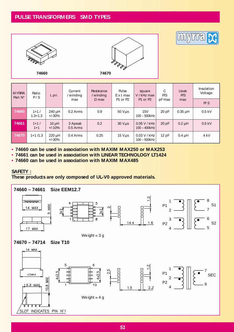
74660 74670
74660 – 74661 Size EEM12.7
Weight 3 g
Weight 4 g
74670 – 74714 Size T10
1 P1 2 P2 4
7 SEC 9
1 P1 2 3 P2 4
8 S17 6 S25
PULSE TRANSFORMERS SMD TYPES
• 74660 can be used in association with MAXIM MAX250 or MAX253 • 74661 can be used in association with LINEAR TECHNOLOGY LT1424• 74660 can be used in association with MAXIM MAX485
SAFETY :These products are only composed of UL-V0 approved materials.
74660 1+1 / 240 µH 0.2 Arms 0.9 50 V.µs 15V 20 pF 0.35 µH 0.5 kV1.3+1.3 +/-30% 100 – 500kHz
74661 1+1 / 10 µH 3 Apeak 0.2 30 V.µs 0.05 V / kHz 20 pF 0.2 µH 0.5 kV1+1 +/-10% 0.5 Arms 100 – 400kHz
74670 1+1 /1.3 220 µH 0.4 Arms 0.25 15 V.µs 0.03 V / kHz 12 pF 0.4 µH 4 kV+/-30% 100 – 500kHz
MYRRAPart N°
RatioP / S
L pri.Current
/ windingmax
Resistance/ winding
Ω max
PulseE x t maxP1 or P2
squareV / kHz max
P1 or P2
CP/S
pF max
LleakP/S
max
InsulationVoltage
P/ S

52
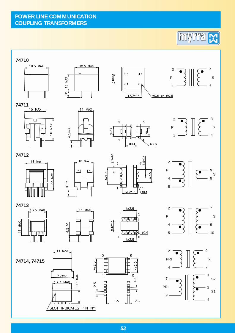
POWER LINE COMMUNICATIONCOUPLING TRANSFORMERS
74710 74711 74712 74713 74714 - 74715
• Designed for coupling signals to power line• Adapted for use with Modem Circuits : ST7537 or TDA5051 or IC/SS
• Models 74710 and 74711 are designed for resonance at 132.5 kHz between the seriescoupling capacitor ( 33nF) and the transformer leakage inductance.
• Models 74712 and 74713 are designed for resonance at 132.5 kHz between the capacitor(6.8nF or 10nF) in parallel with the primary magnetizing inductance.
Safety : All products meet IEC 60950 and IEC60558 requirements74710, 74714 and 74715 : reinforced insulation, creepage distance > 8 mm74712 : reinforced insulation, creepage distance > 6 mm74711, 74713 : Functionnal insulation
74710 2.0 mH +/-40% 44 +/-7% 0.6 Ω / 0.6 Ω 10 – 450kHz 1 / 1 10 mA 4000 EF16-(1 – 3) H-4P
74711 2.9 mH +/-40% 44 +/-7% 1 Ω / 1 Ω 10 – 200kHz 1 / 1 4 mA 1500 U9.8-4P(1 –2)
74712 212 µH +/-10% < 5 µH 0.8 Ω / 0.04 Ω 10kHz – 1MHz 5+1 / 1 500 mA 4000 E16-V-(2 – 5) (2 – 5) 10P
74713 144 µH +/-10% < 5µH 0.5 Ω / 0.5 Ω 10 – 450kHz 5+1 / 5+1 200 mA 1500 E13-V-(2 – 5) 10P
74714 1.3 mH +/-40% < 0.5µH 0.2 Ω / 0.2 Ω 10 – 200kHz 1 / 1 4 mA 5500 T10-(2 – 4) SMD
74715 3.0µH +/-25% < 0.1 µH 0.06 Ω / 0.1 Ω 1 – 20 MHz 2 / 1+1 200 mA 4000 T10-(2 – 4) SMD
MYRRAPart N°
Insulation(Vrms)
PrimaryInductance
( µH )
LeakageInductance
( µH )
Resistanceper windingP / S (max)
Frequencyrange
TurnsratioP / S
Max Sec.current
(50-60Hz rms)Size
53
POWER LINE COMMUNICATIONCOUPLING TRANSFORMERS
74710
74711
74712
74713
74714, 74715
2 P 1
3 S 4
3 P 1
4 S 6
2 P 4 5
9 S8
2 P 4 5
7 S 9 10
7 PRI 9
1 S2 2 S1 4
2 PRI 4
9 S 7

Notes Notes Notes Notes Notes Notes

Notes Notes Notes Notes Notes Notes

Notes Notes Notes Notes Notes Notes