Embed Size (px)
Citation preview

I
R
1
2
3
4
5
6
7
8
9
10
11
12
13
T
14
15
A
PHONE: 516.328.3300 • FAX: 516.326.8827 • WWW.SDP-SI.COM
Metric
0 10
13-5
MAGNETIC PARTICLE SLIP CLUTCHES
DESIGN:The magnetic particle slip clutch uses a sealed, steel outer housing and permanentmagnets arranged alternately (north and south poles) around a central hub. The space between the housing and the magnets is filled with a ferromagnetic compound (hysteresis particles). The particles align themselves along the flux pattern between the steel housing and the mag-nets, creating a magnetic coupling between them. (See Fig. 1)
The torque rating is determined by the number of particles added. The clutches can be manufactured in the range from 2.82 to 39.55 N • cm. Because the coupling is magnetic, torque value remains stable over time, temperature and speed value.
APPLICATIONS: One of the applications is for paper feeding devices on scanners, copy machines and fax machines. Paper is an abra-sive material. Pages often stick together and usually the thickness of the paper is different. The paper feeding device uses a powered roller to “urge” the top sheet off an infeed stack toward the interface between a second pair of rollers just beyond the urging mechanism. On the second pair, one of the rollers is powered; the second is unpowered, spring-loaded against the first and rides on a shaft linked to the chassis through the magnetic particle clutch. With no paper in the feeder mechanism, the clutch slips; when a single page is drawn between rollers, friction between the rollers and the paper remains high enough to maintain slippage and paper passes through the mechanism normally.
If two or more pages are drawn in, the coefficient of friction between the pages is not high enough to drive the unpow-ered roller. The slip clutch now acts as a drag brake holding back the lower roller. The roller stalls, preventing all but the top page from continuing through the feed device.
Steelhousing
Magnetic bridge
Magnetic particles
Shaft Rotor (permanent magnet)
Fig. 1Reversible MagneticParticle Slip Clutch

I
R
1
2
3
4
5
6
7
8
9
10
11
12
13
T
14
15
A
PHONE: 516.328.3300 • FAX: 516.326.8827 • WWW.SDP-SI.COM
Metric
0 10
13-6
MAGNETIC PARTICLE SLIP CLUTCHES
ZERO MAINTENANCECONSTANT TORQUE LEVELS
MATERIAL:Shell - SteelEnd Caps - Plastic
FEATURES:Requires no powerUses permanent magnets and magnetic particlesLong operational lifeSealed from contamination
SPECIFICATIONS:d Tolerances:Fig. 1: +0.1/0Fig. 2: +0.022/0*D1 Tolerance: 0/-0.033 (h8)
**Optional torques available only by special order.
When the slip clutch is to be subjected to any radial or axial thrust, use of the ball bearing design is required. Units should be used on horizontal shafts only.
Catalog Number
METRIC COMPONENT
Fig. 1 Plastic Bearings
Fig. 2 Ball Bearings
D2
DHubDia.
l StaticN •m
Opt. Range**N •m
Torque ± 10% Nomimald
Bore d1
D1HubDia.
l1EndLgth.
LTotalLgth.
Max.Allowable
Speedrpm
Weightkg
888
8888
202027
30303737
S90APLMP08030028S90APLMP08060028S90APLMP08120035
S90APLMS08099037S90APLMS08150037S90APLMS08199044S90APLMS08301044
202020
32323232
111111
10101010
171717
20*20*20*20*
27.527.534.5
37374444
0.0300.0600.120
0.0990.1500.1990.301
0.019 - 0.0400.040 - 0.0600.060 - 0.120
0.070 - 0.0990.099 - 0.1500.150 - 0.1990.199 - 0.301
300300250
400400300300
0.0250.0250.030
0.1200.1200.1500.150
2.5 2.5 2.5
2222
111111
––––
3.1
2.4 ± 0.1
Ø2.1
Ød ØDØD2 ØD1 Ød1
L
ØD2 ØD1
1
lL
5l1
l 5l1
M3 x 0.5 (3x)EQ. SP. ON AØ26 ± 0.2 B.C.
4Fig. 1
Fig. 2
Ød ØD
4
+0.2 0
+0.2 0

I
R
1
2
3
4
5
6
7
8
9
10
11
12
13
T
14
15
A
PHONE: 516.328.3300 • FAX: 516.326.8827 • WWW.SDP-SI.COM
Metric
0 10
13-7
MAGNETIC PARTICLE SLIP CLUTCHES WITH SHAFT
ZERO MAINTENANCECONSTANT TORQUE LEVELSINTEGRAL SHAFT
MATERIAL: Shell - SteelEnd Caps - PlasticShafts - Steel
FEATURES:Requires no powerUses permanent magnets and magnetic particlesLong operational life
*Optional torques available only by special order.
Catalog Number **
METRIC COMPONENT
Fig. 1 Plastic Bearings
Fig. 2 Ball Bearings
DShaftDia.
0-0.03
D2
D1HubDia.
S lMax.
AllowableSpeed
rpmStaticN • m
Opt. Range*N • m
Torque ± 10% Nomimal
8888
88888
20202734
2626333340
S90BPLMP08030025S90BPLMP08060025S90BPLMP08120032S90BPLMP08181039
S90BPLMS08099028S90BPLMS08150028S90BPLMS08199035S90BPLMS08301035S90BPLMS08398042
2.42.42.42.4
–––––
15151515
1515151515
20202020
3232323232
300300250200
400400300300200
0.0300.0600.1200.181
0.0990.1500.1990.3010.398
0.019 - 0.0400.040 - 0.0600.060 - 0.1200.120 - 0.181
0.070 - 0.0990.099 - 0.1500.150 - 0.1990.199 - 0.3010.301 - 0.398
S
180
Fig. 1
Fig. 2
2.52.550 l
180
250 l
ØDØD1ØD2
ØDØD1ØD2
M3 x 0.5 (3x)EQ. SP. ON A Ø21 B.C.
NOTE: When the slip clutch is to be subjected to any radial or axial thrust, use of the ball bearing design is required. Units should be used on horizontal shafts only.
I
R
1
2
3
4
5
6
7
8
9
10
11
12
13
T
14
15
A
PHONE: 516.328.3300 • FAX: 516.326.8827 • WWW.SDP-SI.COM
Metric
0 10
13-8
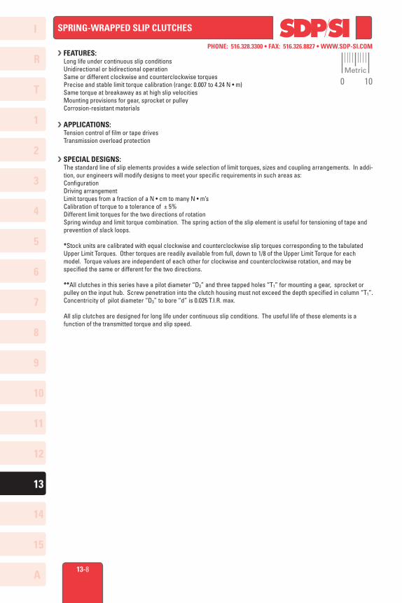
SPRING-WRAPPED SLIP CLUTCHES
FEATURES:Long life under continuous slip conditionsUnidirectional or bidirectional operationSame or different clockwise and counterclockwise torquesPrecise and stable limit torque calibration (range: 0.007 to 4.24 N • m)Same torque at breakaway as at high slip velocitiesMounting provisions for gear, sprocket or pulleyCorrosion-resistant materials
APPLICATIONS:Tension control of film or tape drivesTransmission overload protection
SPECIAL DESIGNS:
The standard line of slip elements provides a wide selection of limit torques, sizes and coupling arrangements. In addi-tion, our engineers will modify designs to meet your specific requirements in such areas as:ConfigurationDriving arrangementLimit torques from a fraction of a N • cm to many N • m’sCalibration of torque to a tolerance of ± 5%Different limit torques for the two directions of rotationSpring windup and limit torque combination. The spring action of the slip element is useful for tensioning of tape and prevention of slack loops.
*Stock units are calibrated with equal clockwise and counterclockwise slip torques corresponding to the tabulated Upper Limit Torques. Other torques are readily available from full, down to 1/8 of the Upper Limit Torque for each model. Torque values are independent of each other for clockwise and counterclockwise rotation, and may be specified the same or different for the two directions.
**All clutches in this series have a pilot diameter “D3” and three tapped holes “T1” for mounting a gear, sprocket or pulley on the input hub. Screw penetration into the clutch housing must not exceed the depth specified in column “T1”. Concentricity of pilot diameter “D3” to bore “d” is 0.025 T.I.R. max.
All slip clutches are designed for long life under continuous slip conditions. The useful life of these elements is a function of the transmitted torque and slip speed.

I
R
1
2
3
4
5
6
7
8
9
10
11
12
13
T
14
15
A
PHONE: 516.328.3300 • FAX: 516.326.8827 • WWW.SDP-SI.COM
Metric
0 10
13-9
SPRING-WRAPPED SLIP CLUTCHES
Covered by U.S. Patents and Patents Pending
Catalog Number
METRIC COMPONENT
LD S
dBore+0.025 0
TSet
Screwl2l1 l3
D1
Max.Wt.
gD2
Max.
Upper* Limit
Torque N • m
D4 T1
D3 0 -0.025
Fig.No.
11111221111112222111111
26.726.731.531.531.535.335.335.335.342.442.447.847.847.847.847.847.847.847.847.858.458.458.4
161625.425.425.431.7531.7538.138.147.547.547.547.557.15 57.1557.1557.1566.55 66.5566.5576.276.276.2
4.574.575.335.335.335.845.845.845.846.356.357.377.377.377.377.377.378.138.138.13
–––
3 4 4 6 8 6 8 6 8 6 81012 6 81012 810 12161920
2.032.032.412.412.413.33.33.33.33.33.33.33.33.33.33.33.33.33.33.35.725.725.72
18.2918.2921.5921.5921.5923.8823.8823.8823.8830.4830.4834.0434.0434.0434.0434.0434.0433.2733.2733.2750.1750.1750.17
S9940YMSWC16X03S9940YMSWC16X04S9940YMSWC25X04S9940YMSWC25X06S9940YMSWC25X08S9940YMSWC32X06S9940YMSWC32X08S9940YMSWC38X06S9940YMSWC38X08S9940YMSWC48X06S9940YMSWC48X08S9940YMSWC48X10S9940YMSWC48X12S9940YMSWC57X06S9940YMSWC57X08S9940YMSWC57X10S9940YMSWC57X12S9940YMSWC67X08S9940YMSWC67X10S9940YMSWC67X12S9940YMSWC76X16S9940YMSWC76X19S9940YMSWC76X20
0.760.761.021.021.021.021.021.021.021.021.021.021.021.021.021.021.021.021.021.021.171.171.17
M1.6M1.6M3M3M3M4M4M4M4M4M4M4M4M4M4M4M4M5M5M5M62@
120°
131322.422.422.425.725.725.7323238.438.438.438.451.151.151.151.151.151.176.576.576.5
9.5 9.512.67512.67512.67512.67512.67512.67512.67512.67512.67512.67519.02519.02519.02519.02519.02519.02519.02519.02528.5528.5528.55
11.43 11.43 17.27 17.27 17.27 17.27 17.27 17.27 17.27 17.27 17.27 17.27 17.2718.818.818.818.818.818.818.8
27.94 27.94 27.94
12.712.7
16.51 16.51 16.5123.523.523.523.519.219.2
29.72 29.72 29.72 29.72 29.72 29.72 29.72 29.72 29.7237.637.637.6
0.064± 0.007
0.141± 0.014 0.339± 0.035 0.565± 0.057 0.847± 0.085 1.059± 0.106
1.695± 0.170
2.540± 0.250
3.390± 0.340
M2X3M2X3M2X3M2X3M2X3M2X3M2X3M3X4M3X4M3X4M3X4M3X4M3X4M3X4M3X4M3X4M3X4M4X5M4X5M4X5M2X3M2X3M2X3
26 26 68 68 68117117213213355355482482582582582582794794794993993993
OUTPUT OUTPUT
LL
T T
ØDØD
ØD1 ØD1
ØD3 ØD2 ØD3 ØD2
ØD4 ØD4
T1T1
Ød Ød
SS
l3 l3
l2
l2l1
l1
CUSTOMER'S**INPUT
Fig. 2Fig. 1
CUSTOMER'S**INPUT
* or ** See Preceding Page

I
R
1
2
3
4
5
6
7
8
9
10
11
12
13
T
14
15
A
PHONE: 516.328.3300 • FAX: 516.326.8827 • WWW.SDP-SI.COM
Metric
0 10
13-23
HYSTERESIS BRAKES AND CLUTCHES
TECHNICAL INFORMATION
APPLICATION EXAMPLE:To select a brake to tension a 7-inch (178 mm) diameter pay-off reel in a system requiring total (web or strand) tension of 2 lbs. (8.9 N) and a process speed of 600 FPM.
BRAKE TORQUE (T) = Force (F) X Radius (D/2) T = 2 lbs. (8.9 N) X 3.5 in. (88.9 mm) = 7 lb. in. (791 Nmm) or T = 32 oz. X 3.5 in. (88.9 mm) = 112 oz. in.
SLIP SPEED (rpm) = linear velocity (V) (in/min) / circumference (in.) or linear velocity (V) (mm/min) / circumference(mm) rpm = 600 ft/min X 12 / (π X 7 in.) or (183 m/min X 1000) / (π X 178 mm) rpm = 327
ENERGY (W) = Energy Dissipation requirement is calculated using basic DISSIPATION horsepower formula X 746 watts/HP W = (T (lb. in.) X rpm / 63025) X 746 or (T (Nmm) X rpm / 7145221) X 746 W = (7 lb. in. X 327 rpm / 63025) X 746 = 27 watts or (791 Nmm X 327 rpm / 7145221) X 746 = 27 watts
Total Web/strandTension (F)
Velocity/Feed Rate (V)
HysteresisBrake
Full RollDia. (D)
3.77.5 15 22
3775 150 225
373746 1500
22503730
oz in lb in
1600 100
400
200
120
32
16
8
2.52.01.6 .1
10
1
.005
.01 .02 .03
.05
.1 .2 .3 1 2 5.0
.5 3
rpm100
200
400
800
1200
rpm172
5
3450
6000
12000
24000
example
WATTS
HORSEPOWER
Quick Check: The curves to the leftcan be used as a quick check to verify the kinetic power calculation. Simply locate the required torque on the vertical axis, move horizontally until you intersect the appropriate speed line, and then read vertically (up or down) to obtain the resulting watts or horsepower.
Selection: From the data on the following pages it can be seen that an S90HYB-120024 Hysteresis Brake which has a rated torque of 120 oz. in. (847 Nmm), a maximum speed capability of 12000 rpm, and an energy dissipation capability of 75 watts continuous, would be the proper selection for this application.
Note: In a clutch application, slip speed is the difference in rotational speed between the input and output members of the clutch assembly. In the above example, tensioning was being accom-plished with a clutch inserted between a take-up reel and a motor driving at 500 rpm. The actual slip used to compute the energy dissipation requirements would be 500 rpm (clutch input speed) - 327 rpm (clutch output speed = 173 rpm). This dif-ference in speed would obviously impact the result for energy dissipation.

I
R
1
2
3
4
5
6
7
8
9
10
11
12
13
T
14
15
A
PHONE: 516.328.3300 • FAX: 516.326.8827 • WWW.SDP-SI.COM
Metric
0 10
13-24
ØD ØC
EF
H
J
P N
G
FE
ØB ØA
K THREAD x L DEEP,3 HOLES EQ. SP.ON A ØM B.C.
R
HYSTERESIS CLUTCHES
MAINTENANCE-FREEINFINITELY ADJUSTABLETORQUE INDEPENDENT OF SLIP SPEED
COIL DATA:Voltage: 24V DC
∆ Shaft & Hub Tolerance (h8):8 mm -0.022
12 & 16 mm -0.02719 mm -0.033
34.93 & 41.28 mm -0.039
Maximum recommended speed is 3600 rpm.
Catalog Number *
METRIC COMPONENT
OutputInertiakg • m2
InputInertiakg • m2
Max.Dissipation
CapacityWatts
Max.Wattage@ rated
VDC@ 25°C
Min.Static Torque@ rated
VDC N • m
Max. Drag Torque
De-Energized & Degaussed
N • m
A± 0.4
B∆h8
C∆h8
0.8472.825
17.29 x 10⁻³
97.18 x 10-30.0110.050
88
S90HYCM108A08S90HYCM162A12
1.86 x 10⁻³
14.52 x 10-380
150108161.9
1619
812
Catalog Number *(Ref.)
D∆h8
E± 0.15
F± 0.4
J± 0.4
GMin.
H± 0.15
LMin.
N± 0.7
P± 0.3
Weightkg
R± 0.3
K M
92.7125.2
45.656.4
M4M5
2532
19.125.4
34.9341.28
3.40213.154
54.781.8
139.8184
0.70.7
50.863.5
4.35.6
9.514.3
S90HYCM108A08S90HYCM162A12
The projections shown are per ISO convention.
* To be discontinued when present stock is depleted.

I
R
1
2
3
4
5
6
7
8
9
10
11
12
13
T
14
15
A
PHONE: 516.328.3300 • FAX: 516.326.8827 • WWW.SDP-SI.COM
Metric
0 10
13-26
ELECTROMAGNETIC SPRING WRAP CLUTCHES
VERY FAST RESPONSEFRICTION-FREE OPERATIONUNIDIRECTIONAL INPUT
COIL DATA: Voltage: 24V DCResistance: 185 ± 10% ohms
SPECIFICATIONS:Static Torque: 30 lbf in. (3.4 N • m) Cycle Life: 1 x 10⁶ @ 30 lbf in.Max. Operating Speed: 1200 rpmPower: 3.5 watts nominalOperating Temperature: 32°F to 140°F (0°C to 60°C)
Dimensions in ( ) are mm.
BBore
in. (mm)Catalog Number
INCH COMPONENT
.2505-.2530 (6.362-6.427)
.2505-.2530 (6.362-6.427)
.3130-.3185 (7.950-8.090)
.3130-.3185 (7.950-8.090)
*S90SWB–13AA04**S90SWB–13AB04*S90SWB–13AA05
**S90SWB–13AB05
BBore
mm (in.)Catalog Number
METRIC COMPONENT
*S90SWBM13AA06**S90SWBM13AB06*S90SWBM13AA08
**S90SWBM13AB08
6.01-6.09 (.237-.239)6.01-6.09 (.237-.239)8.01-8.09 (.315-.318)8.01-8.09 (.315-.318)
* Hub Input (HI)CW / Shaft Input (SI)CCW** Hub Input (HI)CCW / Shaft Input (SI)CW
3X120°
.31(7.87)
Ø.737(18.72)
Ø1.05(26.67)
.210 ± .003(5.33 ± 0.08)3 X
+.15-.051.10+3.81-1.2727.94
MAX.
*HI-CW/SI-CCW
*HI-CCW/SI-CW1.055 ± .010
(26.80 ± 0.25).755 ± .010(19.18 ± 0.25) .272 ± .010
(6.91 ± 0.25).096 ± .010
(2.44 ± 0.25)
Ø.5115 ± .0015(12.99 ± 0.038)
.103 ± .003(2.62 ± 0.08)2 X RAD. FULL
.945 ± .010(24 ± 0.25)
.013 ± .013(0.33 ± 0.33)
.157(4) MIN.
B
FLYING LEADS 24 AWG 12 in. (30 cm) LONG
( (
Ø1.312 ± .010(33.32 ± 0.25)
0 1Inch
I
R
1
2
3
4
5
6
7
8
9
10
11
12
13
T
14
15
A
PHONE: 516.328.3300 • FAX: 516.326.8827 • WWW.SDP-SI.COM
Metric
0 10
13-27
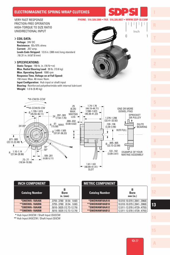
ELECTROMAGNETIC SPRING WRAP CLUTCHES
VERY FAST RESPONSEFRICTION-FREE OPERATIONHIGH-TORQUE TO SIZE RATIOUNIDIRECTIONAL INPUT
COIL DATA: Voltage: 24V DCResistance: 93±10% ohms Current: .257 amp.Leads Ends Stripped: 12.0 in. (300 mm) long standard .19/.31 in. (4.9/7.8 mm)
SPECIFICATIONS:Static Torque: 150 lb. in. (16 N • m) Max. Radial Bearing Load: 30 lb. (13.6 kg)Max. Operating Speed: 1000 rpmResponse Time, Voltage on at Full Speed: 150 msec Max. 40 msec Nom.Input Configuration: Hub input or shaft inputBearing: Reinforced polyetherimide with internal lubricant Weight: 1.0 lb (0.45 kg)
BBore
in. (mm)Catalog Number
INCH COMPONENT
.3755-.3780 (9.54- 9.60)
.3755-.3780 (9.54- 9.60)
.5010-.5035 (12.73-12.79)
.5010-.5035 (12.73-12.79)
*S90SWA–18AA06**S90SWA–18AB06*S90SWA–18AA08
**S90SWA–18AB08
BBore
mm (in.)Catalog Number
METRIC COMPONENT
*S90SWAM18AA10**S90SWAM18AB10*S90SWAM18AA12
**S90SWAM18AB12
10.010-10.079 (.3941-.3968)10.010-10.079 (.3941-.3968)12.011-12.078 (.4729-.4755)12.011-12.078 (.4729-.4755)
SPROCKET OR PULLEY
Ø .895-.905(22.73-22.99)
*HI-CW/SI-CCW
**HI-CCW/SI-CW
Ø 1.795-1.815(45.59-46.11) .297-.303
(7.54-7.70)3X
R MAX..61(15.50)
Ø 1.495-1.505(37.97-38.23)
70°50°
.189-.201(4.80-5.11)
3X120°
.871-.885(22.12-22.48)
1.10-1.14(27.94-28.96)R
.73-.77(18.54-19.56)
1.74-1.76(44.19-44.71)1.590-1.623
(40.38-41.23)
1.276-1.296(32.41-32.92)
.25(6.35)MAX.
MATINGLUG
.000-.032(0.00-0.82) .130-.136
(3.30-3.46)W/R FULL
.122-.142(3.09-3.61)
B
1.61-1.63(40.89-41.41)
SLOT
ONE OR MORE DOWEL PINS
OILITEBEARING
EXAMPLE OF YOUR MATING ASSEMBLY
* Hub Input (HI)CW / Shaft Input (SI)CCW** Hub Input (HI)CCW / Shaft Input (SI)CW
0 1Inch

I
R
1
2
3
4
5
6
7
8
9
10
11
12
13
T
14
15
A
PHONE: 516.328.3300 • FAX: 516.326.8827 • WWW.SDP-SI.COM
Metric
0 10
13-35
FLANGE-MOUNTED CLUTCHES
ZERO-BACKLASH ARMATUREFOR PARALLEL LOADS
COIL DATA:Voltage: 24V DC
Other voltages and dissimilar bore combinations are available as special order.
Keyway Dimensions
8WidthHeight
6Bore27
39.4
* Typical torque after burnishing; units shipped burnished.** Length equals K including initial working air gap at installation.∆Keyway not available in rotor.◊To be discontinued when present stock is depleted.
The projections shown are per ISO convention.
Catalog Number ◊
METRIC COMPONENT
RBore
EnergyDissipationN • m/min
RotorInertia
kgf • m • sec2
ArmatureInertia
kgf • m • sec2Max
.W
atta
ge Static* TorqueN • m Disengagement
msecEngagement
msec
Armature
∆ 66
0.561.13
55
237.3 400
1822
0.28 x 10⁻⁶
0.57 x 10-658
0.40 x 10⁻⁶
0.68 x 10⁻⁶
S90CF9M11A0606S90CF9M15A0606
Catalog Number ◊(Ref.)
Weightkg
TSet
ScrewsAir Gap
Length**MF LEDCBA
K
∆ 3.24
–M3
29.739.6
38.0550.77
0.10.2
31.339.2
12.8816.03
8.48.4
33.344.4
1.31.5
31.838.9
0.1/0.220.15/0.33
S90CF9M11A0606S90CF9M15A0606
ØC
L
ØR
ØM
OVER KNURL
ØA
ARMATURET, 2 PLACES90° APART
E
300 mm MIN.
FROTOR
ØB ØD, 4 PLACESEQ. SPACED
K**